

Page 1
Page 2
SPECIFICATIONS 3
STATEMENT
SAFETY PRECAUTIONS
CHARGING METHOD AND CAUTIONS
ASSEMBLY 8~10
2.4GHz RADIO SYSTEM 11~14
PRE-FLIGHT INSPECTION AND ADJUSTMENT
NORMAL FLIGHT
IN-FLIGHT ADJUSTMENT
HELPFUL TIPS
TROUBLESHOOTING
SPARE PARTS LIST
3
4~5
6~7
15
16~17
18
18
19
20~21
Art-Tech reserve the right to alter the specifications at any point.
Please contact your nearest retailer for the latest specifications.
All information correct at time of print E&OE.
Page 3
Thank you for purchasing the STOL. The STOL is a Short Take-Off and Landing airplane. It uses leading
and trailing edge flaps and also features a drop bay. The STOL is fitted with a powerful brushless motor
and Li-Po battery giving good performance and control with high stability.
The RTF version includes: 2.4GHz transmitter and receiver, ESC, motor, batteries, servos and charger.
The PNP version includes: ESC, motor and servos.
You will need to add a suitable transmitter, receiver and battery pack.
STOL Features:
1. Leading and trailing edge flaps.
2. Drop bay with parachuting figure.
3. Large tyres for landing on rough ground or grass.
4. Tough, coloured EPO airframe for durability.
5. Powerful brushless motor.
Wingspan: 1254mm (49.4”)
Length: 988mm (38.9”)
Height: 412mm (16.2”)
Weight: 1440g (50.8oz)
Wing Area: 23.6dm
Wing Loading: 61g/dm
1. This model is not a toy, and is only suitable for responsible pilots.
Please keep in mind that you are responsible for the safe operation of this model and any damage or harm
that may be caused due to improper usage.
2. Please setup this model correctly according to instructions and make sure that
all body parts are kept away from any rotating parts to avoid personal injury or
damage to your model.
3. The user bears full responsibility for proper operation and use of this model.
Art-Tech or any of its distributors can not be held responsible for any liablity or loss
due to improper operation.
4. You must read and fully understand this manual before attempting to fly your model.
Brushless Motor: ST3511-760KV
ESC: 30A Brushless
Servos: 9g x 7
RC System: EFLY-Bll 6CH 2.4GHz (RTF Version Only)
Battery: 11.1v 1800mAh Li-Po (RTF Version Only)
Page 4
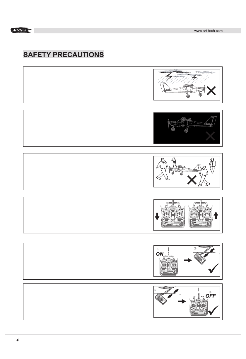
Do not fly in unsuitable weather conditions such as:
Thunderstorms, rain or excessive winds.
Do not fly near an airport, railway line, road,
telephone lines or power lines.
Do not fly where there are crowds of people.
Only fly at specially designated flying sites.
Make sure your model and radio system are
functioning correctly before attempting to fly.
Always make sure your transmitter is turned on before
connecting your flight pack to the model.
Always disconnect the battery from the model before
turning your transmitter off.
Page 5
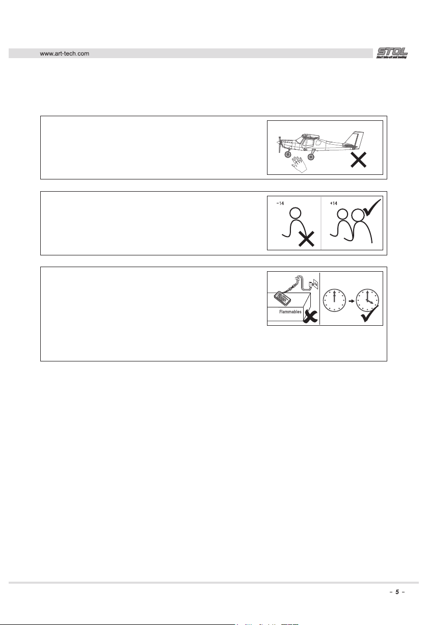
Do not attempt to catch the model while flying.
Beginners should have an experienced pilot to
help them while learning to fly.
This product is not recommended for children under
the age of 14.
Never charge your batteries on a flammable base.
We recommend charging on a concrete surface or in
a dedicated charging bag.
When the battery is fully charged, disconnect it from the
charger, and remove the charger from the wall socket.
Always supervise a charging battery and do not leave
it unattended.
Page 6
(for 2 or 3 cell batteries)
1. Insert the charger's plug to the power outlet, the red and green lights flash, then the green
light remains on, the red goes out, which shows the charger is working, you can now charge the
battery.
2. Insert the battery’s balance plug into the correct charging port as shown, the red light
comes on which shows battery is charging.
3. Charge the battery for about one and a half hours, when red light goes out, the battery is
charged.
Safety Instructions for Your Li-Po Charger
1. Keep the charger away from water or other liquids.
2. Do not attempt to use the incorrect voltage input, or charge a non-suitable battery.
3. Do not insert anything into the cooling vents of the charger.
4. Charge on a non-flammble surface.
5. Only charge 1 battery at a time.
6. The charger is for Li-Po batteries only.
7. The charger should be kept out of the reach of children
8. Do not leave the battery and charger unattended during charging.
9. If anything abnormal occurs, stop charging immediately.
(Battery getting hot, battery swelling)
10. Do not disassemble the charger.
11. Do not attempt to charge a warm battery.
Page 7

SAFETY INSTRUCTIONS FOR YOUR LI-PO BATTERY
1. Do not disassemble or reconstruct the battery.
2. Do not short-circuit the battery.
3. Do not use or leave the battery near a fire, stove or heated place (more than 80 degrees).
4. Do not immerse the battery in water.
5. Do not leave the battery in direct sunlight.
6. Do not damage, throw or strike the battery
7. Always thoroughly inspect a battery that has been involved in a crash.
8. Do not use a battery with damage or deformation.
9. Do not charge a warm battery. Allow it to cool completely before attempting to charge.
10. Do not reverse polarity or over discharge the battery.
11. Do not directly connect the battery to the mains power socket or 12v supply.
12. Do not use the battery for unspecified equipment.
13. Do not touch a leaking battery directly, please wash your skin or clothes with water if
they come into contact with liquid leaking from the battery.
14. Do not mix the battery with other battery types during usage.
15. Do not continue charging the battery over the prescribed time.
16. Do not put the battery into the microwave oven or high-pressure container.
17. Do not use the battery nearby the place which generates static electricity (over 64V).
18. Do not charge the battery when the temperature is under 0 or over 45 degrees.
19. If you find the battery leaking, smelling or abnormal, stop using it and discard the battery in
the proper manner.
20. The battery must be charged on a non-flammable surface.
21. Keep the battery away from the children.
22. Use the specified charger and observe charging requirements (under 1A).
23. The battery should always be monitored during charging
Storing your Li-Po battery
1. The battery should be charged at no more than 1C using a specified charger.
2. The battery should not be discharged at over 15C to avoid damaging the battery.
3. When the Li-Po battery is stored for more than 3 months, it needs to be recharged to
maintain its voltage, and ensure its life time.
4. The battery should be fully charged before storage.
Page 8
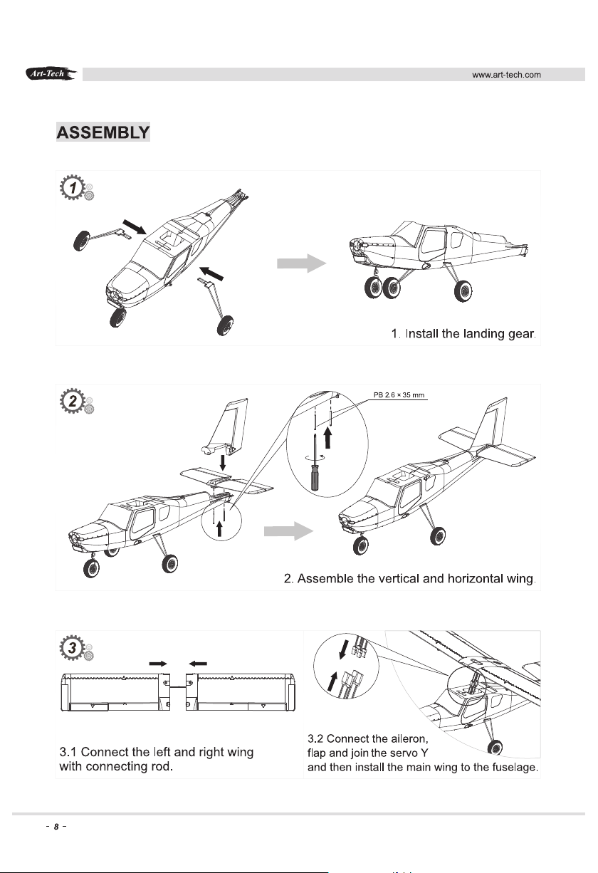
leads
Page 9
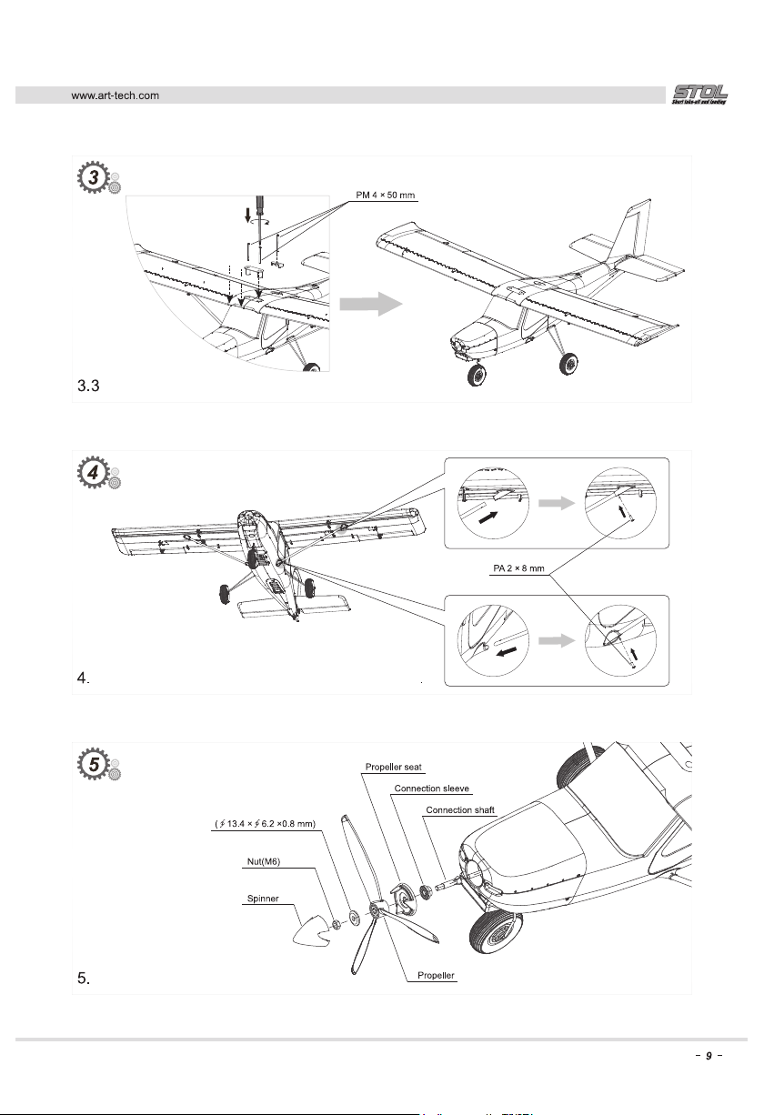
Screw the wings on.
Attach the cabane struts.
Washer
Fit the propeller
Tighten the prop nut securely, but do not overtighten.
Page 10
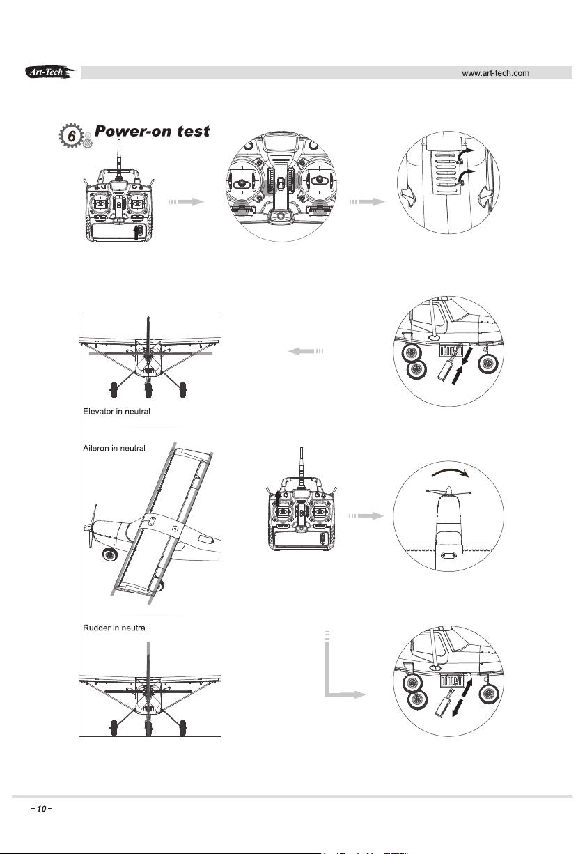
6.1 Switch on the transmitter 6.2. Centre the control surface trims.
Note throttle trim and stick are at
the lowest position.
6.4. Connect the battery and make sure the control surfaces
are in a neutral position.
6.5. Open the throttle and check the propeller runs in
the correct direction.
6.3. Open the battery hatch
6.6. Disconnect the battery and the model is ready to fly.
Page 11
www.art-tech.com
Operating Manual for the radio control system
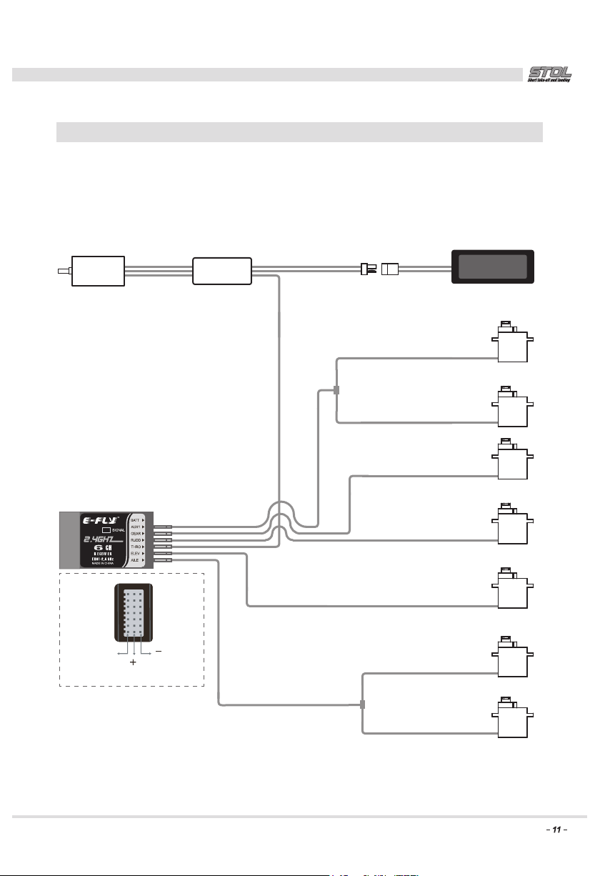
Components to the R/C system
a transmitter, a receiver, a servo, a speed controller
The sketch map for connecting the receiver:
Motor ESC
Signal
(White line)
(Black line)
(Red line)
Battery
Leading / Trailing edge flap (L)
Leading / Trailing edge flap (R)
Parachute servo
Rudder servo
Elevator servo
Aileron servo (L)
Aileron servo (R)
Page 12
www.art-tech.com
Transmitter Description and Functions
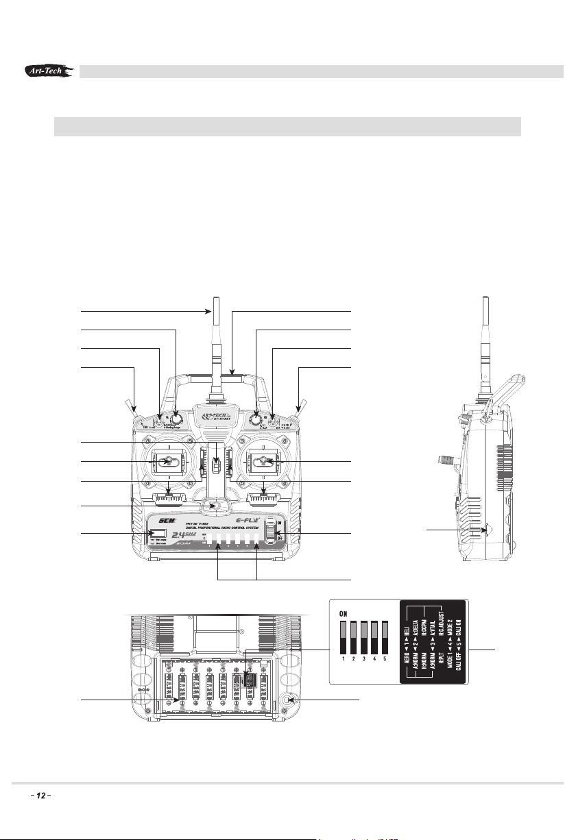
ETB62A-2.4GHz is a 6 channel full-range 2.4GHz R/C device. It uses direct sequence spread
spectrum (DSSS) technology, giving good anti-interference high signal stability and reliability.
It can be used for aeroplanes and helicopters with up to 6 channels and has features such as
dual rates (D/R), a simulator interface, Mode change functions and a low voltage alarm.
The ETB62A-2.4GHz radio has a ground to ground range of up to 200 metres and a ground to air
range of up to 300 metres.
A
C
E
G
I
L
N
O
B
D
F
H
KJ
M
P
Q
TS
R
U
Page 13
www.art-tech.com
A: Aerial
B: Handle
C: VA Dial
(1) Aircraft: Rudder movement range
(2) Helicopter: Pitch adjustment
D: VB Dial
(1) Aircraft: Flap movement range.
(
2) Helicopter: Pitch length adjustment
E: Drop bay switch
F: Dual Rate(D/R) Switch
G: Training mode switch
H: Function Switch
(1) Aircraft: Flap control switch
(2)Helicopter: Flight mode switch
I: Neck strap hook
J: Left stick
1) Mode ll: Throttle and rudder
2) Mode l: Elevator and rudder
K: Right stick
1) Mode ll: Elevator and aileron
2) Mode l: Throttle and aileron
L: Trim
M: Trim
N: Transmitter status indicator LED
O: Bind Button
P: On/Off Switch
Q: Servo reversing switches
(1) CH1 reverse switch
(2) CH2 reverse switch
(3) CH3 reverse switch
(4) CH4 reverse switch
(5)
CH5 reverse switch
(6) CH6 reverse switch
R: Charging Jack
S: Battery bay for transmitter
T: Simulator Jack
U: Mode Switch
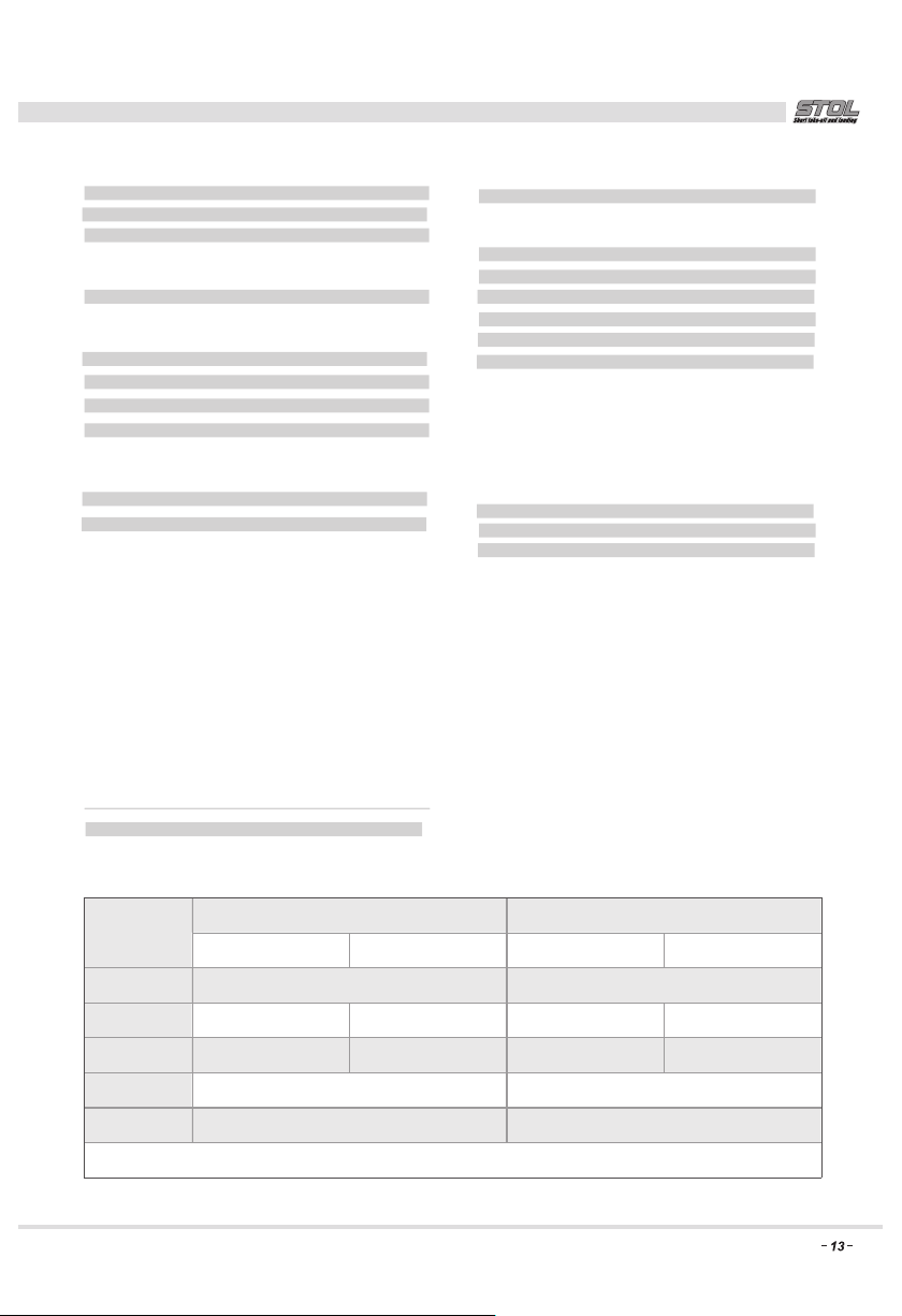
R/C Mode select switch Instruction:
Switch NO.
Helicopter Mode
1
2
3
4
5
NOR
ONOFF
Aero plane Mode
Normal Wing
Normal tail wing
Note:Those functions are marked with “*” will be valid once you restart.
Helicopter Mode Aero plane Mode
Transmitter in helicopter ModeTransmitter in airplane Mode
CCPM Mode Delta wing mixture control
Sensitivity adjustment V-tail mix controlPLT ajustment
Mode 2*Mode 1*
Assembly Calibrations on*Assembly Calibrations off*
Page 14
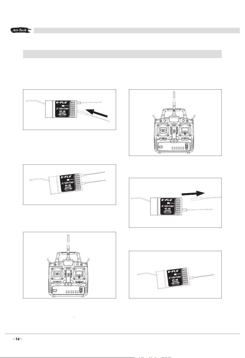
Binding your DSSS series 2.4GHz R/C system
Place the transmitter and the receiver within one (1) metre of each other.
Do not press the bind button when the transmitter and receiver are bound, as it will break the bind!
1. Plug the bind plug into the receiver in
BATT. socket. Connect a power supply to
the receiver. The receiver’s LED will flash.
2. Press the transmitter’s bind button, then
turn on the transmitter.
www.art-tech.com
3. The LED on the receiver will go solid.
This indicates that the bind is successful.
5. Press the transmitter’s bind button again.
The indicator light will flash for a few seconds.
Once it turns green, the transmitter is ready
to use.
4. Remove the bind plug, the LED will flash.
6. The receiver’s LED turns solid again,
which means that the radio system is bound
and ready to use.
Page 15
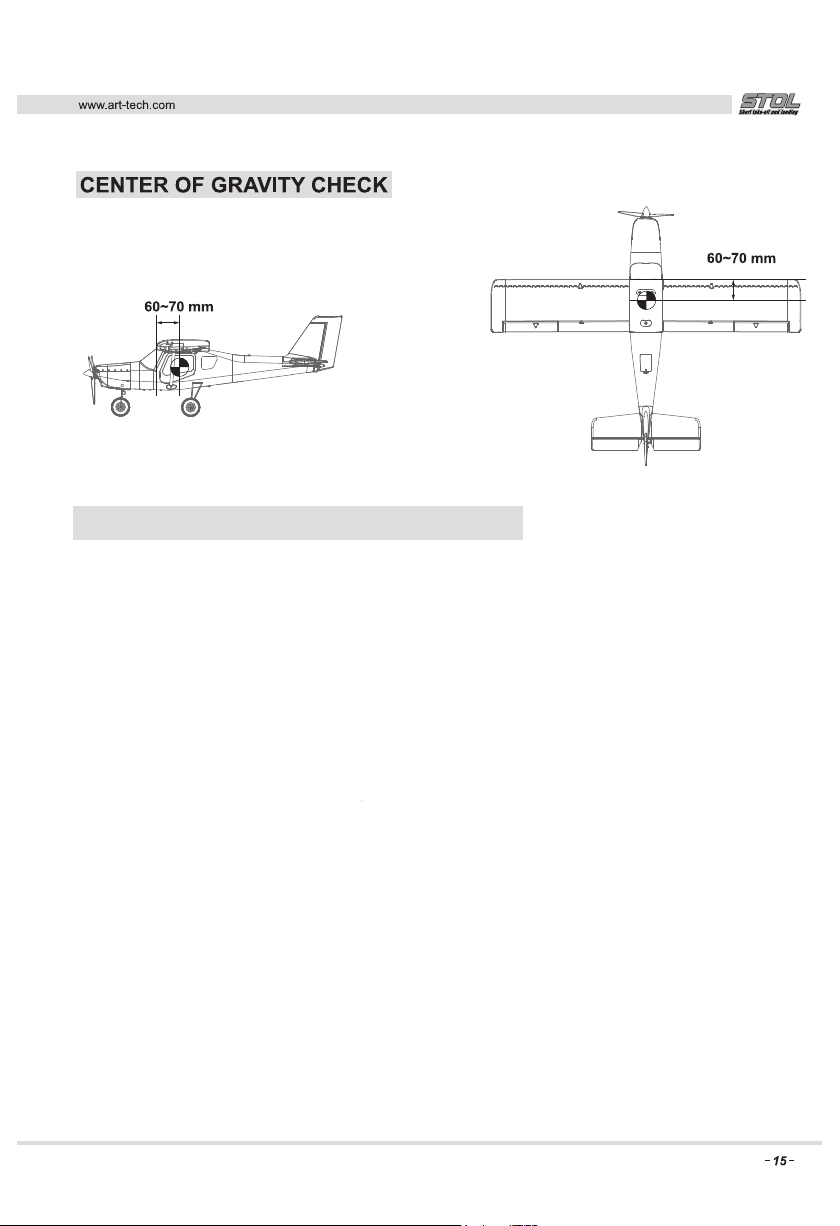
Make sure the model’s CoG is within the range
shown here. In the ideal situaion, the CoG is
between 60~70mm from the leading edge of
the wing.
PRE-FLIGHT INSPECTION AND ADJUSTMENT
1. Install 8 ‘AA’ cells into the transmitter according to the battery’s polarity, then turn on the transmitter.
Install the full charged flight battery into the battery compartment of the fuselage and connect the battery
to the electronic speed controller (ESC).
2. The right stick of transmitter controls the aileron when pushed left or right: when you push the stick
to the left, the left aileron of plane will lift and the right aileron of plane will drop in response and vice versa
for when the aileron is pushed right.
Before flying, put the trim of aileron to the middle position and then adjust both the ailerons to the neutral
position with the control rod.
3 .The left stick on the transmitter controls the power of motor when pushed backwards for forwards
When holding the fuselage of the plane, please keep objects away from the propeller to avoid hurting
people or damaging the propeller. If you pull the left stick to the lowest position, the motor will stop.
Now the motor is on standby. You can check the motor by pushing the stick up slowly.
4. The up and down movement of the right stick of transmitter controls the movement of the elevator.
When you pull the stick back, the elevator of plane will lift and vice versa when you push the stick forward.
The best state before flying is the elevator sticks and trim are all in the neutral position.
5. The left stick on transmitter controls the rudder when you push the stick to the right, the rudder of
plane will turn right and vice versa when the stick is pushed left. The rudder stick and trim should be neutral
before flying.
6. If the servos and motor give no response during setup, please check all connections and make sure the
battery is fully charged and the transmitter and receiver are bound together.
7. Check the CoG of the model. The proper CoG position should be 60~70 mm away from the leading edge,
please refer to the picture. If in any doubt contact your dealer.
Note: The transmitter and receiver must be the same 2.4GHz protocol. Unmatched sets will not be
compatible and may cause loss of control.
Page 16
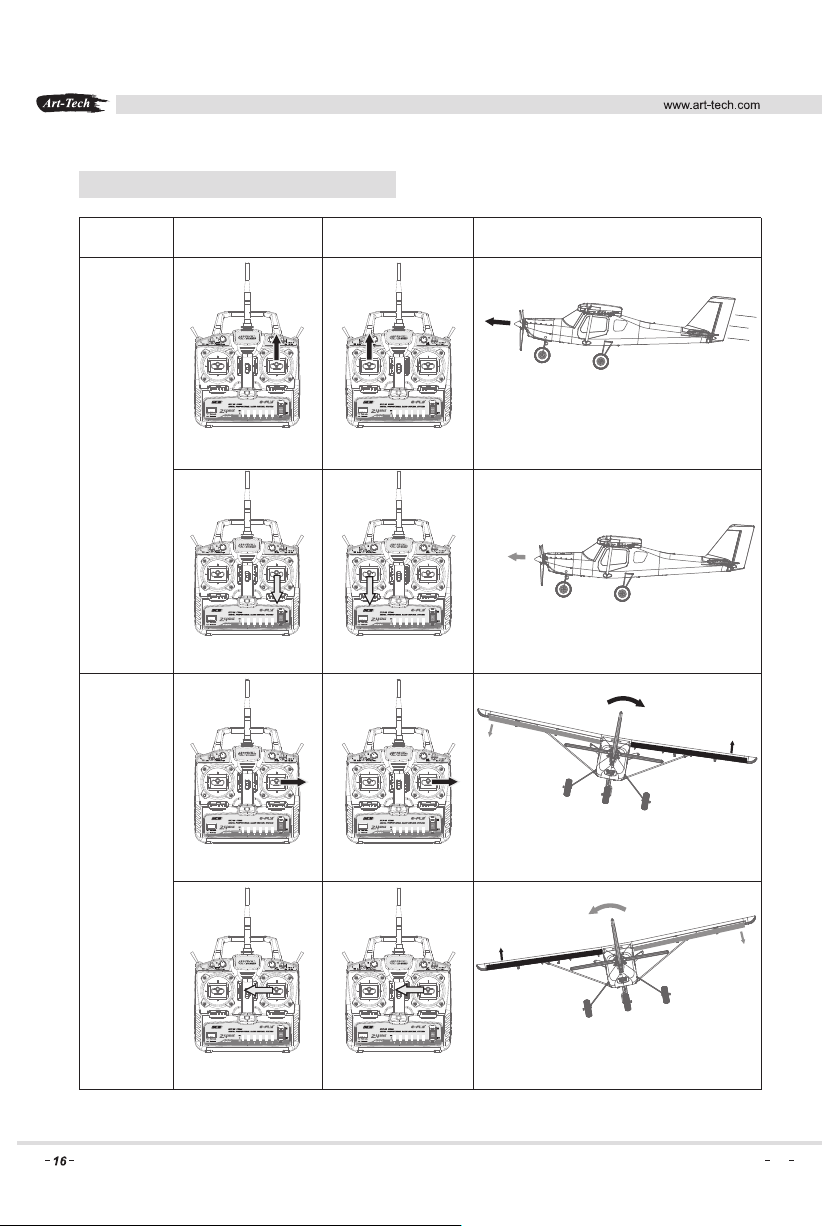
NORMAL FLIGHT
Mode 2Mode 1 Illustration
Speed up
Throttle
Aileron
Right stick
pushing up
Right stick
pulling down
Right stick
moving right
Left stick
pushing up
Left stick
pulling down
Right stick
moving right
Speed down
(Back View)
The body incline to right
Right stick
moving left
Right stick
moving left
Back View)
(
The body incline to left
Page 17
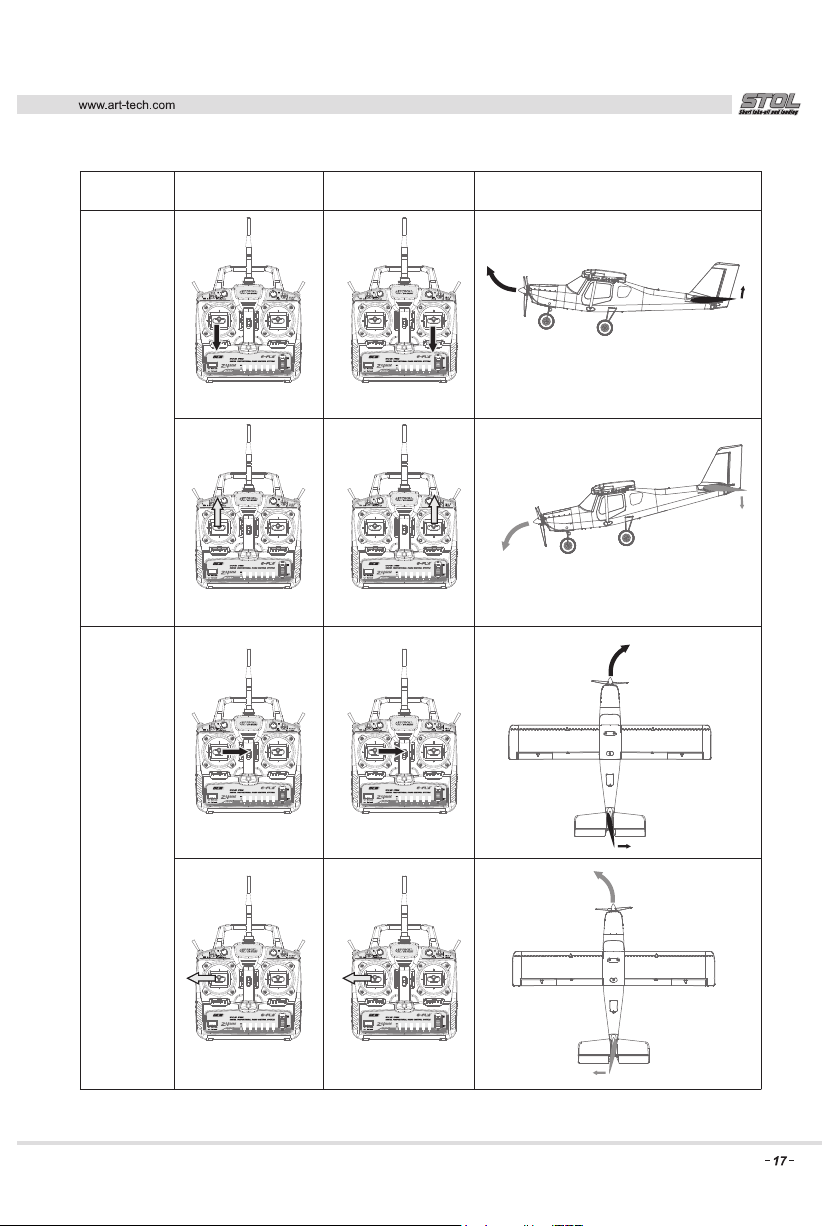
Mode 2Mode 1 Illustration
Elevator
Rudder
Left stick
pulling down
Left stick
pushing up
Left stick
moving right
Right stick
pulling down
Right stick
pushing up
Left stick
moving right
Nose turn up / ascending
Nose turn down / descending
Nose turn right
Nose turn left
Left stick
moving left
Left stick
moving left
Page 18

www.art-tech.com
IN-FLIGHT ADJUSTMENT
1. Before flight a radio range check should be conducted. A minimum distance of 200m between the radio
and model with the model on the ground whilst maintaining full control of the model is recommended.
If you cannot control the model at 200m, then do not fly!
2. Make sure both your flight pack, and your radio batteries are fully charged before attempting to fly.
3. During flight, if the model is ‘yawing’ to the right, adjust the rudder trim to the left to correct this.
If the model is ‘yawing’ to the left, then adjust the rudder trim to the right.
4. If the model is trying to drop its nose during flight, then adjust the elevator trim downwards to correct
this. If the model is trying to lift its nose, then adjust the elevator trim upwards.
Upon landing, if you have had to make excessive trim adjustments to the elevator, it is advisable to
double-check your centre of gravity.
If your centre of gravity is correct, then you may wish to check your elevator clevices and ensure
your control surfaces are level.
5. If the model is ‘banking’ to the left, then adjust the aileron trim to the right. If the model is ‘banking’
to the right, then adjust the aileron trim to the left.
HELPFUL TIPS
1. If you have a flight simulator we recommend that you practice with it before flying your radio control
model. It will give you an understanding of how the transmitter operates the model and increase
your chances of a successful first flight.
2. Before flight, check all control surfaces operate in the correct direction and move freely.
3. On your first flight, we recommend flying to a height of around 100m and reducing the throttle to
30%. This will allow you to get used to the way the model handles and performs.
4. When taking off, position yourself into the wind, this gives better airflow over the wings and allows
the model to take-off more easily.
5. Always fly your model in front of you, never fly behind yourself or over your head.
6. To increase flight times, spare battery packs are preferred over a larger battery as this will not
upset the performance or weight distribution of the model.
Page 19
www.art-tech.com
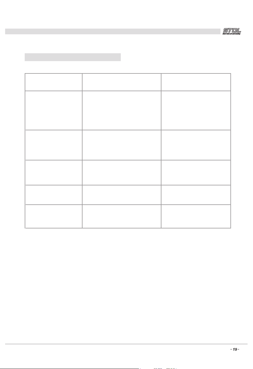
TROUBLE SHOOTING
Problem Cause Solution
Motor does not run
No reaction from
control surfaces
Does not fly straight
Does not climb
Limited control range
1. Flight battery is not fully charged.
2. Transmitter batteries are low.
3. Loose connection to the motor.
4. The motor may be damaged.
5. The radio is not bound.
1. The servo is plugged in incorrectly
2. The servo is damaged.
3. The radio is not bound.
1. The rudder is out of trim.
2. The main wing is not aligned.
1. The battery is not fully charged.
2. The elevators are out of trim.
The batteries are almost flat Install new batteries
1. Charge the batteries
2. Install fresh batteries
3. Inspect all wire connections.
4. Install new motor.
5. Re-bind the radio.
1. Check the servo connections.
2. Replace the servo.
3. Re-bind the radio.
1. Adjust the rudder trim.
2. Check the main wing.
1. Charge the battery.
2. Adjust the elevator trim.
Page 20
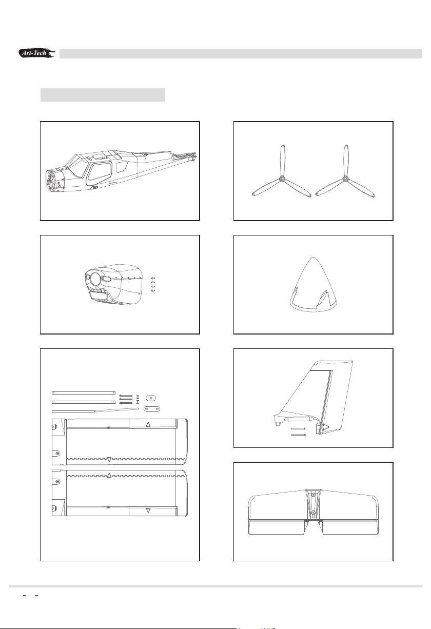
SPARE PARTS LIST
www.art-tech.com
NO. : 5201R
Fuselage
NO. : 5206R
Cowling
NO. : 5204R
Propeller
NO. : 5209R
Spinner
NO. : 5205R
Vertical Wing
20
NO. : 5202R
Main Wing
NO. : 5203R
Horizontal Wing
Page 21
www.art-tech.com
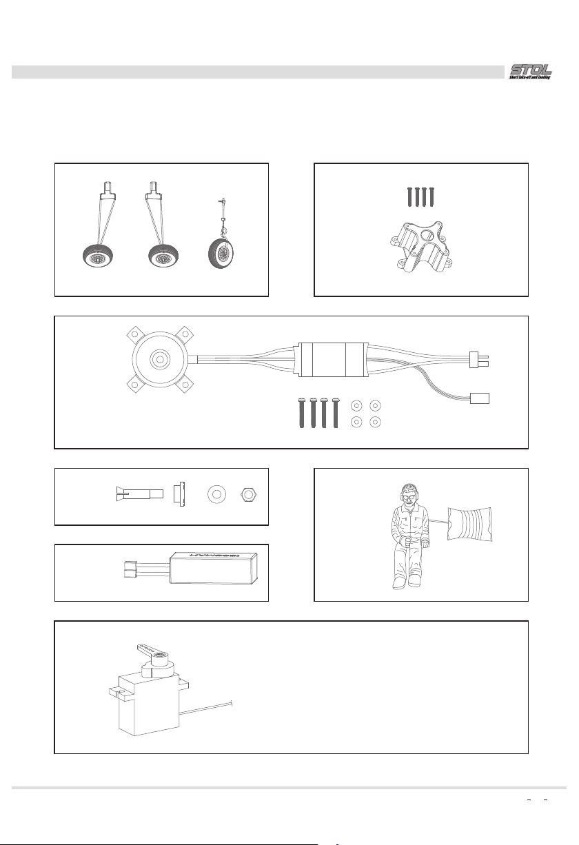
NO. : 5207R
landing gear
NO. : 3A03M
Integrated out runner brushless motor set
NO. : 5229C
Propeller adaptor
NO. : 3F023
11.1V,1800mAh/20C Lipo Battery
NO. : 5210R
Motor mount
NO. : 5208R
Parachute
NO.: 3502E
Extension cable length 180 mm
Servo(9g)
NO.: 3502P
Extension cable length 300 mm
NO.: 3502Q
Extension cable length 450 mm
21
Page 22

MADE IN CHINA
 Loading...