

Page 1
USER S MANUAL
Page 2
Contents
★Specifications for standard version
★Warning:
★Please read the following instructions and fully understand it.
★Flying adjustment
★Charge mode and warning
★Assembly
★Adjustment method of the servo slowness switch
★Trouble shooting
★Valuable experience
01
01
02
02
03
05
08
08
09
★Operating Manual for the radio control system
★The process of frequency bind for DSSS series 2.4GHz R/C system
★Normal flight
★Inspection and adjustment before flying
★Adjustment during the flying
09
11
12
13
15
Specifications may change without notice, please refer to the real one for configuration. 2010.5
Page 3
Please read this manual carefully and follow the instruction
Than k yo u fo r pur chas i ng Art -Tec h Ces sna 182 5 00 c lass Rad io C o ntro lled Mod e l Aero p lan e .
Wit h a s uper sca led and stab l e p e rfor m ance , T h is m odel is a n op t imal mod e l f o r m i ddle -lev e l a n d
adv a nced pilo t . Bu t with the h elp f rom a n exp e rien ced t u tor i t ca n be u s ed as a tra iner airc r aft f or
the n o vice .
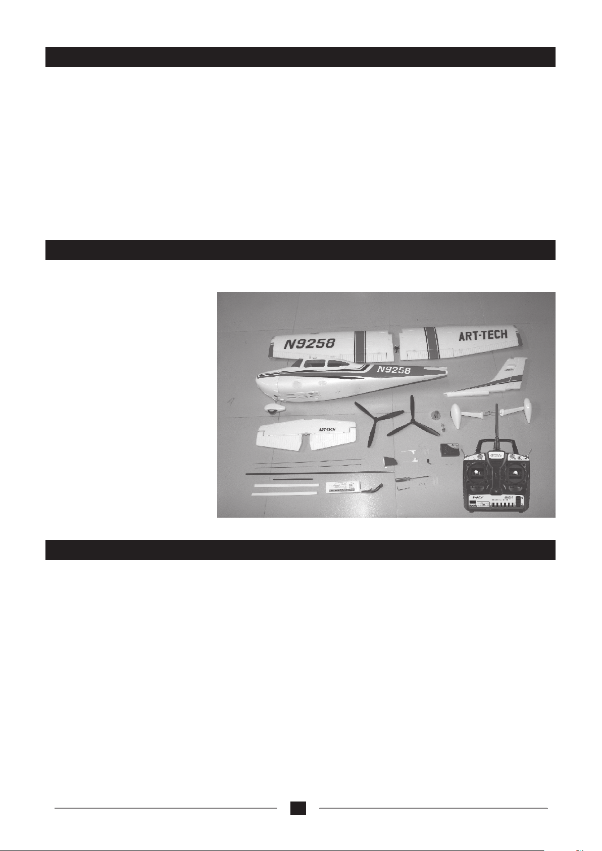
Con f igur a tion s ( the co n figu rati o n with b e vari e d from d iffe rent v e rsio ns)
RTF v ersi o n: Eve ryth i ng inc lude d
ARF - 1 vers ion( P NP): E v eryt hing i n clud ed exc e pt for t he Tx an d Rx
ARF - 2 ve r sion : Ev e ryth i ng inclu d ed ex cept for the Tx, Rx, batt ery, ES C, balan c e ch a rger and
ada p tor.
Specifications for standard version
Wingspan: 1300mm
Length: 993mm
Weight: 1350g
CG position: 35%
Thrust Ratio: 0.8
Max Flying Time: >10mins
Battery: 11.1v, 2400mAh Lipo
ESC: 30A
Motor: 3715-01c (KV=820rpm/v)
outer runner brushless
Wing Area: 23 dm
Wing load: 58g/ dm
2
2
Warning:
1. Thi s mo dels is not a toy, it is for inte rmed i ate and exp erie n ced hob b y e nthu s iast .
2. Ple a se pay much at t enti on to t he warn i ng info r mati on i n t his man u al.
3. It is high l y r ecom m ende d t o fl y t h is mode l u n der gui d ance fr o m a n e xper i ence d m o del pil o t i f
y ou are a n ovic e/be g inne r.
4.A c rash ca n ha ppen if the mo d el is n ot flow n a c cord i ng to thes e in stru c tion s a n d i f t he p ilot is
n ot expe r ienc ed e noug h.
5.To ga in t he most fr o m t his mode l y o u n eed to impr ove step by st e p f rom basi c t r aini ng up t o
p erfe ct f ligh t b e fore mo ving ont o a e roba tics .
1
Page 4
Please read the following instructions and fully understand it.
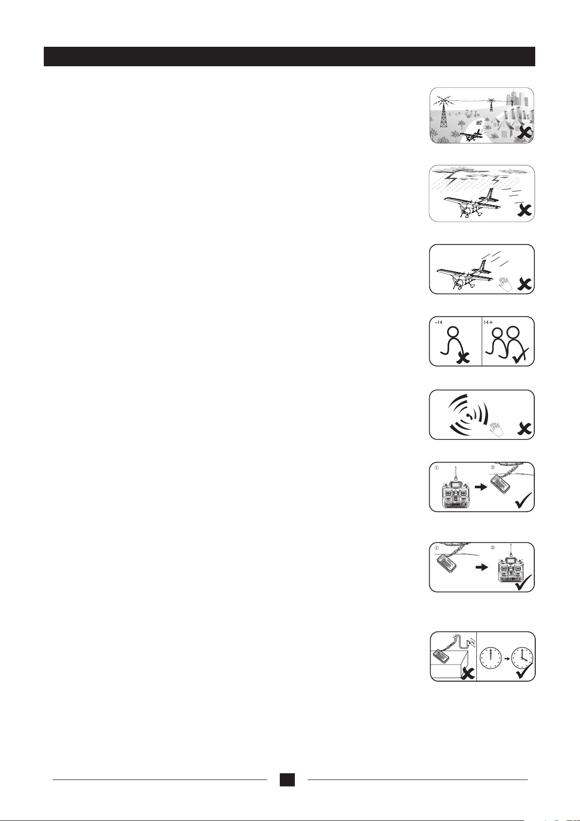
1) The Cessna 182 500 model is not suitable to fly in the places listed below, in
a crowd of people, around telegraph or electrical poles, around cars, near to
traffic or next to a full size air field/airport.
2) Do not fly in bad weather or in high winds, the lower the wind the better the
model will fly.
1
3) Never attempt to catch the aircraft in your hands as this could lead to serious
injury.
4) This model is recommended for people over the age of 12 and with experience,
if under this age or a novice then we recommend you get tuition from an
experienced model pilot.
5) Always unplug the flight battery when you finish flying the aircraft.
6) Please always keep clear of the propeller when you connect the flight battery,
the transmitter must be switch on all the time the flight battery is connected.
7) Please remember to turn on the transmitter first before flying and keep away
from the propeller when the flight battery is connected.
8) Please disconnect the flight battery before switching of the transmitter when
you have finished your flight. Not following this strict procedure can result in
an out of controlled model.
2
3
4\5
6
RIGHT
LEFT
SUB
N/DOWN
7
9) Do not charge in or on a wet surface. Please pay attention to the charger while
on charge, the maximum time that the battery should be left on charge is four
hours. It is normal for the battery to get warm during use but not HOT.
10) Never charge on a flammable base such as carpet etc, we recommend that
you charge on a concrete floor or a metal tea tray. When charged disconnect
the battery from the charger and the charger from the wall socket.
Always supervise the battery when charging, do not leave it on its own to
charge just in case of a problem.
2
Flam mable s
RIGHT
LEFT
SUB
N/DOWN
8
9
Page 5
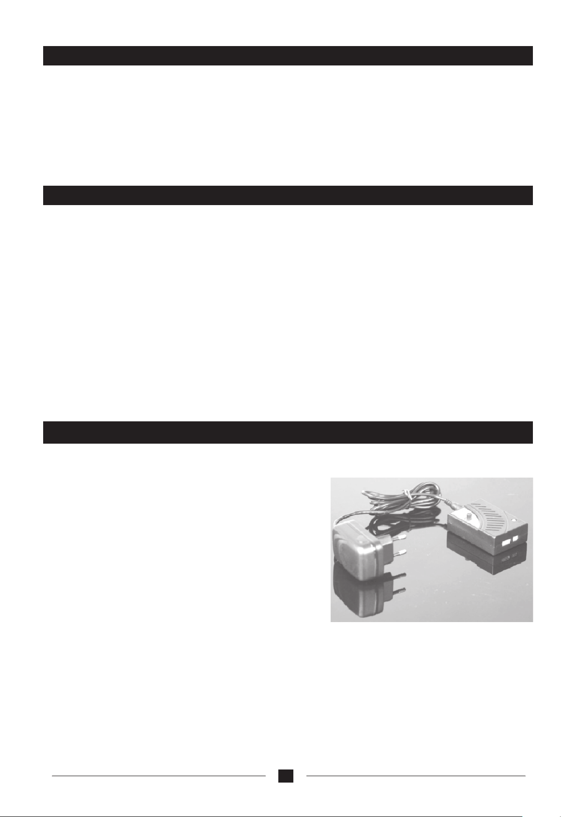
Flying adjustment
1) Cessna 182 will have a better perform when fully charged.
2) Straight flight; please adjust the aileron trim on the transmitter to get the model to fly straight, for
example if you find the model fly’s to the left apply a small amount of right aileron trim until the model
fly’s in a straight line.
3) Horizontal flight; please adjust the elevator trim on the transmitter to get the model to fly horizontally
when cruising at around half throttle. For example if at half throttle the model is diving apply a small
amount of up elevator trim until the model fly’s perfectly on the horizontal axis.
Tips for flying
1. Do not fly the model during bad weather cond itions or high wind.
2. Take off: th e mo del should take off into the wind . Cessna 182 500 class can be hand launched or take
off from the ground. When h an d launching, accelerate the throttle to ful l power and hold the fuselage
firmly (near the CG position), then lif t it o verhead and launch it.
Take off from the ground: Cho os e a smooth track with length and width no less than 5 0*6m. Please
adjust the front wheel before make it tax i wi th full power so that to keep the model moving in a str aight
line. Even during the running take-off period, please adjust the route s li ghtly. When reaching the take
off speed, pull down the rudd er joystick a little to make the model head to the sk y.
3. Cruising; when the model reaches aroun d 100 m height you can lower the throttle and cruis e at
around 1/3 throttle, to trim the model to f ly a t this speed adjust the elevator trim to achi ev e the optimum
horizontal flight path.
4. Landing: Before landing the model, tur n off or decrease the throttle an d put down the flap; then lower
the flying speed. Make sure the gliding dis tance is enough for landing and the model is facing t he wing.
When the plane is approaching the ground, c on trol the elevator servo gently to make the mo de l land
safe. In winds above 5 mph it is not necessary to se the flaps.
Charge mode and warning
Li-Po battery(balance changer)
YTF-1004 Li -poly battery balanc e charger usi ng instru ction
Specifications:
Input volta ge: DC 10V~15V
Output volt age: DC 7.4V&11.1V
Charge curr ent: 0.3A~1.2A
Indicator state:
LED light nea r to the battery plug turn s red: the char ger have
connected t he power supply.
LED light nea r to the DC port turns red: un der chargin g
LED light nea r to the DC port turns green : full charge d
LED light nea r to the DC port extinuish s: no chargin g
Separated b attery detection: The voltage o f any batte ry reaches
4.2V, the charge of i t will cease au tomatically.
Using method:
1. Connect the mans adaptor to the charger as per the above image.
2. Connect the adaptor to the 240v supply, the LED should turn red indicating that it is ready to charge.
3. Connect the battery to the charger per its interface mark. The LED becomes red, which means the
battery is on the way.
4. The LED turns green when fully charged ( if the light is not green after four hours remove from
charge and use any way ) and then the battery is ready to be used.
3
Page 6
Notice
1. Do not insert any conductive into the cooling hole when power is on, or damage will be caused to the charger.
2. While charging is in process, please do not place it near flammable materials.
3. Expect Li poly battery, this charger is not allowed for other kinds of battery.
4. While charging, please keep it out of the reach of Children.
5. When this charger is in use, please do not go away and leave it unwatched, if any abnormality occurs (such as the
power indicator is off, the temperature of the battery rise rapidly, etc.) stop charging immediately.
6. Please do not use power with output voltage higher than 18V.
7. Please do not disassemble the charger or its accessories.
8. When the battery is not cool down, please do not urge to charge it.
Safety instructions for Li-poly batteries
01.Do not dis assemble or reconstr uct the batte ry.
02.Do not sho rt-circuit the batte ry.
03.Do not use or leave the battery nearby the fire, stove or heated place.
04.Do not imm erse the battery in wate r or sea water, do n ot get it wet.
0 5.Do n o t charge t h e b a t t e r y nearby t h e fi r e o r u n d e r the b l a z i n g s u n l i g h t .
06.Do not dri ve a nail into the battery, strike it by hammer or tr ead on it.
07.Do not imp act or throw the battery.
08.Do not use t he battery with conspi cuous damag e or deformation.
09.Do not mak e the direct soldering o n the battery.
10.Do not rev erse charge or over disc harge the bat tery.
11.Do not re verse cha rge or revers e connect.
12 .D o no t co nn ec t the battery to the ordinary charger socket or car cigarette jack.
13.Do not use t he battery for unspeci fied equipm ent.
14.Do not touch th e leaki ng batter y directly, ple ase wash your skin or clothes with water
if they are bede wed by li quid leak ing from the battery.
15.D o no t m i x t h e L i - Poly ba t t ery with oth e r u n -cha r geab l e b a tter y .
16.Do not con tinue charging the bat tery over the p rescribed time.
17. Do no t p ut the ba tte ry in to the mi cro wav e o ven o r h igh -pr ess ure co nta ine r.
18.Do not use t he abnormal battery.
19.Do not use o r keep the battery under t he sunlight .
20.Do not use the battery nearby the place where generates static electricity (over 64V).
21.Do not charge the battery when the environmental temperature is under 0℃ or over 45℃.
22.If you find the battery leaking, smelling or abnormal, stop using it .
23.Keep the b attery away from the chi ldren.
24.U s e t h e s p ecif i ed c harg e r a n d o b serv e ch a rgin g re q u ire m e nt ( unde r 1. 5 A).
25. When usi ng by mi nor s, pa ren ts sh oul d s how t hem th e cor rec t way to char ge.
Caution
1. Use the orig inal charger. Never cha rge the batte ry at more than 1.5 A.
2. Never disc harge the battery at mor e than 5C. Do not d ischarge too long as thi s will damage t he battery.
3. For full fli ght time to be achieved pl ease cycle th e cells through three fl ights.
4. Never char ge the battery on a carpet f loor, this can c ause a fire!
5. In order to ma intain the voltage and e nsure the lif e time of the battery, pl ease recharge it if it has n ot
been used for m ore than three months.
4
Page 7
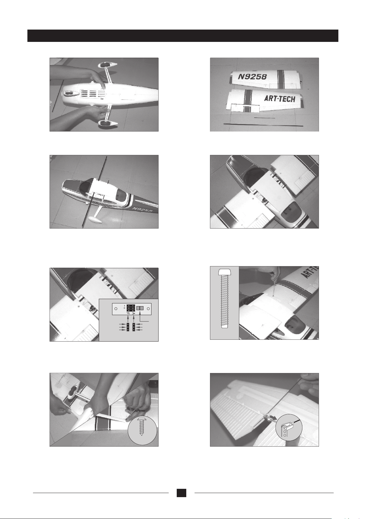
Assembly
1. Please inset the m ain landing gear into t he
fixed seat on the bot h side of the fuselage.
3. Insert the two win g spares to the holes on
the back of the fusel age (The longer spare
should insert int o the hole near the nose pa rt
and the other to the ho le near the tail). Adjus t
the rod length prop erly on both side.
2. Take the main wings and the two wing
connection spar es out of the package
4. Connect the main w ings to the wing
spares, but not to th e bottom.
ailero n
lam pligh t
Blac k line
Red l ine
Whi te line
Bla ck line
Red l ine
Whi te line
fla p
5. Connect the flap s ervos and aileron ser vos/
connector of ligh t system to the relativ e socket
on the fuselage (according to the arrowhead mark),
and then make sure wi ngs are inserted firm ly.
PA2 *4
7. Take out the win g strut, bend it slight ly and
then insert it to the plastic set of the fuselage
and wings , and then connect the ma in wing
support strut to th e both wings. And th en fix it
with two screws.
M4* 25M M
6. Fix the main wings w ith the two Nylon
screws.
8. Take out the sta bilizer set and the lin kage
rod, connect the Z- linkage to the outer ho le
of the elevator ser vo arm.
5
Page 8
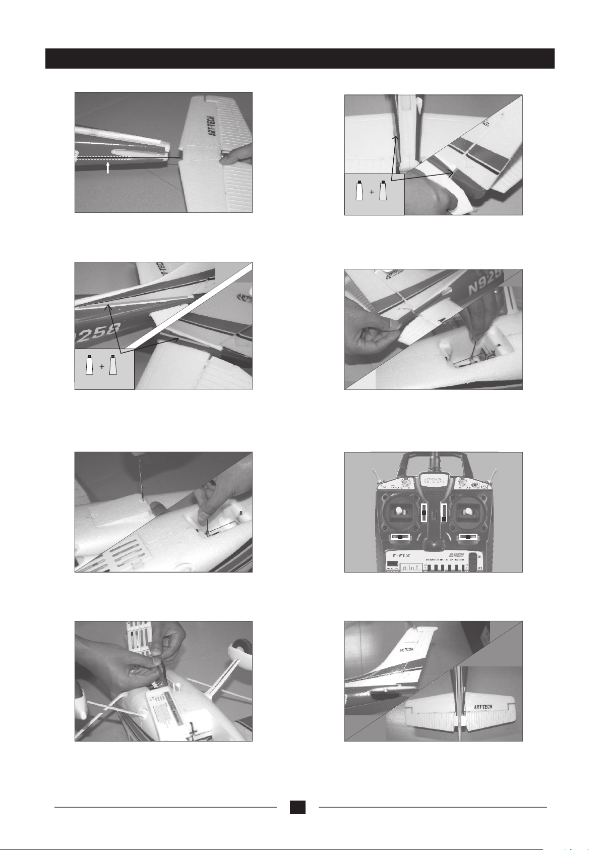
Assembly
Inner pipe
9. Insert the eleva tor push rod into the
fuselage tail.
A B
10. Please push the h orizontal tail plan e into
the slot at the rear of t he fuselage, and chec k
whether it is symme trical, and then stic k the
junction with the AB g lue. Please install t he
tail cover to the cor responding locati on with
the same method.
A B
Insert the vertic al tail fin in to the fusel age slot
11.
as the pictures sho wn, check and make sure t hat
it is in a 90 degree ange l -with the stabilize r tail
plane, make sure it h as been inserted full y to the
to the bottom of the fu selage, and then stic k the
junction with the AB g lue.
13. Undo the two screws on the protected cover,
of then connect the elevator servo rod to the servo
seat as the picture s how.
12. Insert the push r od to the pipe on the right
side of the fuselag e and connect the clevi s to
the outer hole of the rudder servo. And connect
the other end to the ru dder.
14. Put the throttl e stick to the lowest pos ition
and adjust the trims to the neutral position, then
turn the power on.
15. Unfold the batt ery cover; take out the p ower
connector of the ES C, connect the ESC to the f ull
charged battery , and then the lighting s ystem will
start to work.
16. Adjust the rudde r servo and elevator se rvo
to the condition as t he picture show; fast en the
servo fix seat with the hexagon wrench, and then
install the servo c over.
6
Page 9
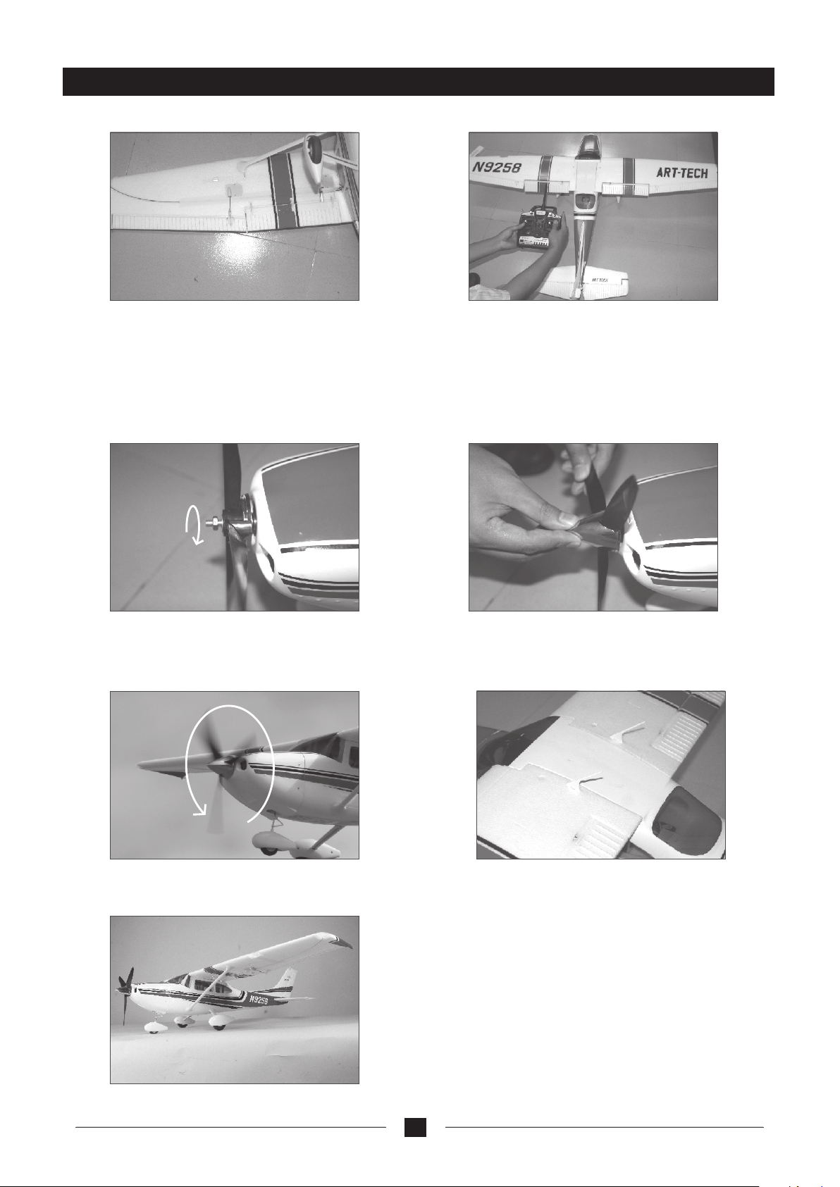
Assembly
17. Check whether t he position when movi ng the
aileron surface i s correct or not. Both si des of the
aileron control s urface should be alig ned under no
operation proce ss, If it is not aligned, p lease
loosen the clevis t o adjust it to the right po sition.
Meanwhile, plea se make sure when moves t he
aileron stick to th e left, the left ailero n should move
upwards and the rig ht aileron should mov e down.
19. Take the ba ttery off the m odel. Install the
propeller (the si de with characters on i t should be
faced to the fusela ge) to the motor shaft, t hen
install the cushi on sheet and nut and then u se the
wrench to tighten t he nut.
18. Check the flap mo vement condition. W hen the
flap channel of the r adio is turned on, the fl ap
should move downw ard to 20~30° slowly an d then
stops. Contrari ly, the flap will re tract. Please be
well noted that fla p should be retracted t o the right
position. If not, please adjust the clevis to correct it.
20. Press the spinner completely to the propeller
and make sure the 3 hoo ks are all fixed to the
spinner seat.
21. Hold the body of th e model firmly then add t he
power slowly. The motor shoul d run clockwise.
(View it from t he rear part of the fusel age)
Remove the antenn a, stick the bottom of
22 .
the antenna with AB gl ue, and plug it directl y
into the antenna slot in the back of the fuselage,
make sure the anten na pointing directi on is in
the rear position .
23. Take out th e battery and the tur n off the
transmitter pow er.
7
Page 10
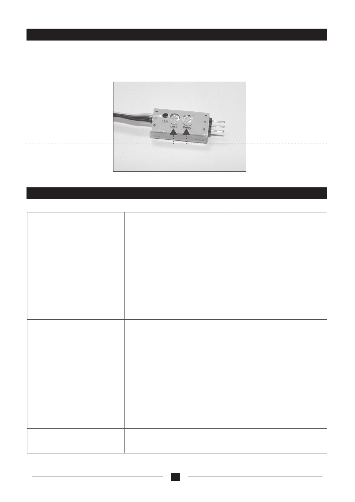
Adjustment method of the servo slowness switch
RTF version with BII Radi o sy stem, flap slowness function availabl e wi th transmitter itself, concerned about
other versions, a extra servo slownes s sw itch is required if you need the slowness fun ct ion but your Tx has
not this function, through channel 5 on t he r eceiver to control the flap servos. pleas e re fer to the pictures for
its location.
This is the angle adjust knob.
The adjust range is 0~90°.
The flap move angle is
suggested to be set to 20~30°.
If the angle is too small, the
flap function will be not so
effective and if the angle is t oo
large, the stability might be
influenced.
Time adju st k nob. It can be
set between 1~14 second.
The suggested setting time
is about 2 seconds.
Trouble shooting
Problem
Motor does not run
No reaction of the
control surface
Can not fly straight
Cause
1. Battery is not fully charged.
2. The battery of transmi tt er is
not sufficient
3. Check the wire connection
inside the model
4. The motor do not work due to
impact or damage.
5. The frequency bindin g of t he
radio system fails
6.Throttle protection(lock sign al
of throttle channel)
The servo cable didn’t plug
1.
properly or inverted plug.
2.The servo is damaged
1.The rudder is not in the center
position of the airframe
2.The main wing is not fixed in
the center position of the airfra me.
Solution
1. Charge the batteries.
2. Install a full charged battery
3. If any problem, please contact
your dealer
4. Change a new motor
5. Please do the frequency
binding again according to the
page 11.
6.push the throttle joy-stick to
its Zero position
1. Check the connection of
the servo cable
2.Change another servo.
1. Adjust the trim switch on
the transmitter
2.Re-assembly the main wing
Can not climb
Limited control range
1. The battery is not fully charged.
2. Two aileron are biased downward
The batteries are almost flat
8
1. Charger the battery
2. Adjust the inching switch on
the Transmitter.
Install new batteries
Page 11
Valuable experience
1. If you have a simulator we recommend that you practice with it before you fly your Cessna182. This will
be very helpful for your first flight.
2. Check and make sure all the control surfaces work normally and move towards the right direction before
flying.
3. We recommend that you take the model up to a height of around 100m and then cruise at around 1/3
power. This will be helpful for ou to get familiar with the performance.
4. Users should control the airplane gently to reduce the risk of crash, and to prolong the working time of
the airplane.
5. The turning radius should not be too tight or the aircraft could become out of control very quickly which
could result in an incident that you did not intend.
6. Please make sure to take off into the wind. The beginners had better fly in breeze and up wing area.
Operating Manual for the radio control system
Components to the R/C system
a transmitter, a receiver, a servo, a speed c on troller
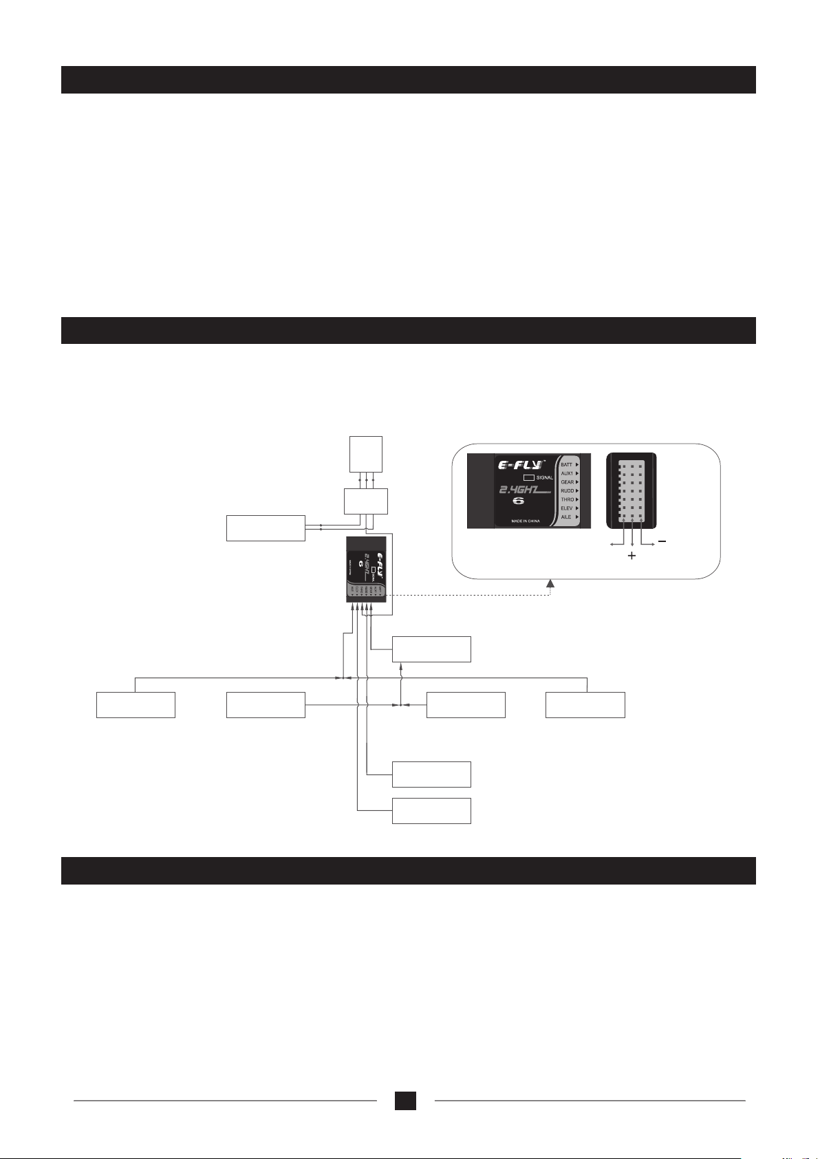
The sketch map for connecting the receiver:
Motor
ESC
Battery
ER61-2.4GHz
RECEIVER
CH
Left ailero n
servo
Left flap
servo
Transmitter particular introduce
Slowness
switch
Right flap
servo
Rudder
servo
Elevator
servo
CH
RECEIVER
ER61-2.4GHz
Signal
(White l ine)
(Red line)
(options ava ilable in accordance
with diff erent dev ices)
Right ailer on
servo
(Black line )
ETB62A-2.4GHz is a 6 channel fu ll-scale 2.4GHZ RC device. It adopt s the technology of direct
sequence spread spectrum (D SS S) to have good anti-interfere nc e, stability and reliability.
It can be used for all ordinary aer op lanes, delta wing aeroplanes, g liders, coaxial helicopters, ge neral
helicopter and CCPM helicopte r models, and so on. It has 6 channel out put and simulator signal interfac e.
It also has such functions as Dua l Ra te(D/R), Mode I and Mode II exchang e and low voltage alarm.
The most characte ri stic feature of ETB62A-2.4GHz R C device is the cordless trainer fu nction. It means
flight instruction can be rea li zed without the trouble of cord con nection and this makes learning eas ier for
green hand.
9
Page 12
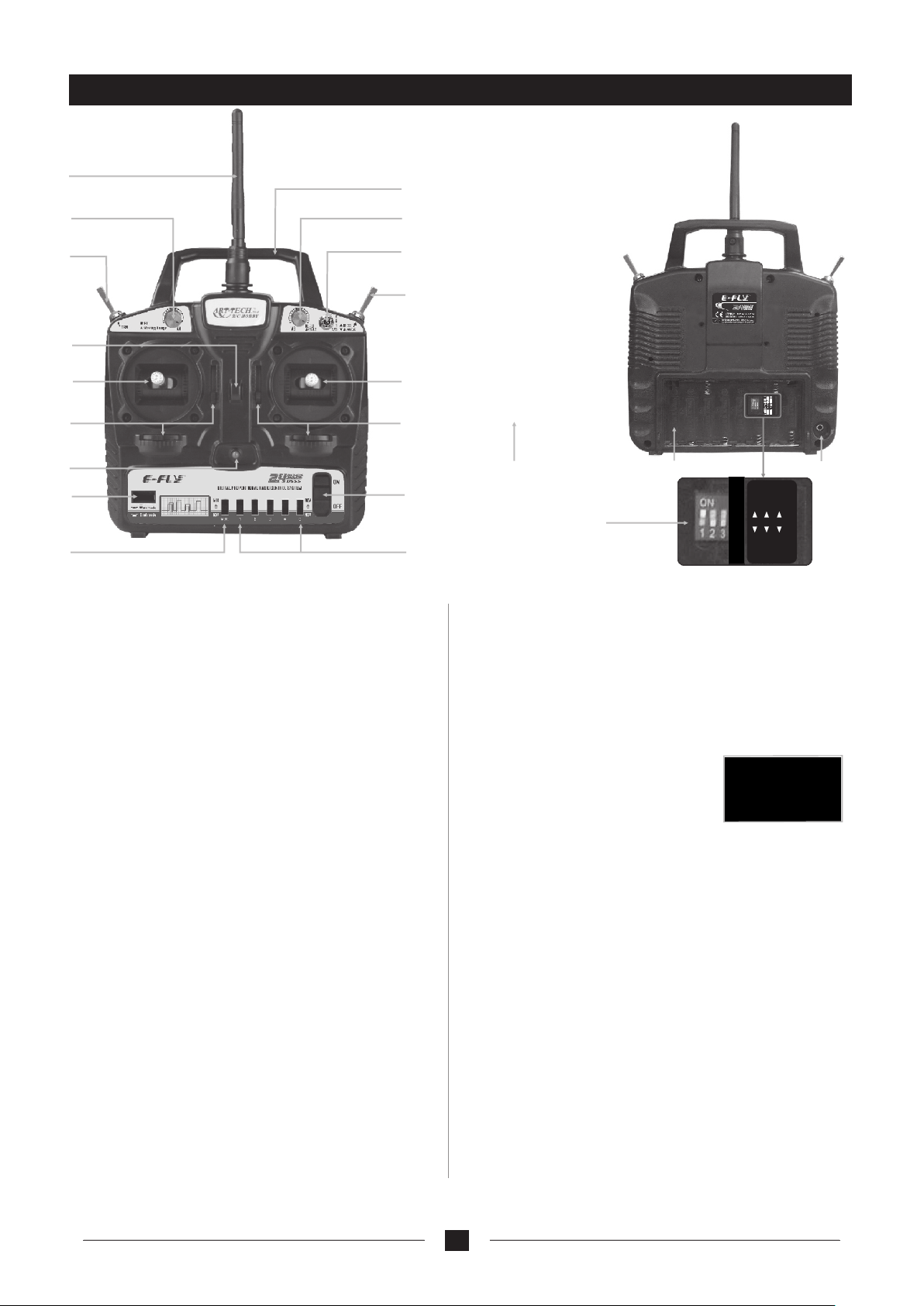
Transmitter particular introduce
A
C
E
B
D
F
H
G
I
K
M
O
P
Configured with 2.4G radio control system with a ground distance of 200meters and Air distance of 500 meters.
A:Antenna
B:Handle
C:VA
1) For aeroplanes, it is for small rate adjustment of
channel 1,2 and 4;
2) For helicopters, it is the fine-tuning for the PIT.
D:VB
1) For aeroplanes, it is for adjustment of channel 6,
usually used for output setting of flap;
2) For helicopters, it is the fine-tuning for the PLT.
E:Trainer switch
F:Dual Rate(D/R) Switch
1) For aeroplanes, When it is 1,it is adjusted by knob A,
from 20% to 100%; When it is 0, it means the turning
range of servos is 100%.
2) For helicopters, The switch is to change the turning
range of servos(100% / 70% )for CH1, CH2 and CH4.
When it is 0, it means the turning range of servos is 100%.
When it is 1, it means the turning range of servos is 70%.
G:Flying Ring
H:Switch
1) For aeroplanes, this switch is for Ch5 and Ch6 and
can be used for collapsible landing gear, aerial camera
and flap control, etc.
2) For helicopters, it is the 3D switch.
I:Joystick
1) If the transmitter is Model 1,CH2 is for elevator and
CH4 for rudder.
2) If the transmitter is Model 2,CH3 is for throttle and
Ch4 for rudder.
J:Joystick
1) If the transmitter is Model 1,CH1 is for aileron and
CH3 for throttle.
Remarks: this TX is throttle protection available , af ter power on, the Throttle (CH3) would be
activated only if you push the throttle joy-sti ck t o its lowest position (Zero Position)
J
L
R
S
T
N
MODE II
U
H E L I
1
2
3
Q
A C R O
MODE I
FR EQ I FRE Q II
2) If the transmitter is Model 2,CH1 is for aileron and
CH2 for Rudder
K:Trim levers
L:Trim levers
M:LED Indicator for Power
N:Switch for Power
O:Bind Button
P:mixed control switch
1) For aeroplanes, NOR means no mixing, MIX means
mixing control for the CH1 and CH2;
2) For helicopters, NOR means
independent aileron, pitch and elevator
servos linked to the swashplate. MIX
means CCPM helicopter. With Aileron
inputs, the aileron and pitch servos tilt the swashplate left
and right; with Elevator inputs, the three servos tilt the
swashplate fore and aft; with Pitch inputs, all three servos
raise the swashplate up and down.
Q:CH1, CH2, CH3, CH4, CH6 reverse switch
1) aileron reverse switch
2) elevator reverse switch
3) throttle reverse switch
4) rudder reverse switch
6) flap / pitch reverse switch
R:Rechargeable plug
S:Battery bay for transmitter
T:Plug for Simulator
U:mode selection switch
1: ACRO for aeroplanes, HELI for the helicopters.
2: MODE 1 and MODE 2 selection.
3: frequency range selection switch, the usable frequency
range of 2.4GHz is different in some countries, for
example, in France only 2.400 ~ 2.454GHz can be used.
2.400 ~ 2.483GHz can be used in the majority of countries,
FREQ1 for 2.400 ~ 2.483GHz, FREQ2 for 2.400 ~ 2.454GHz
10
Page 13
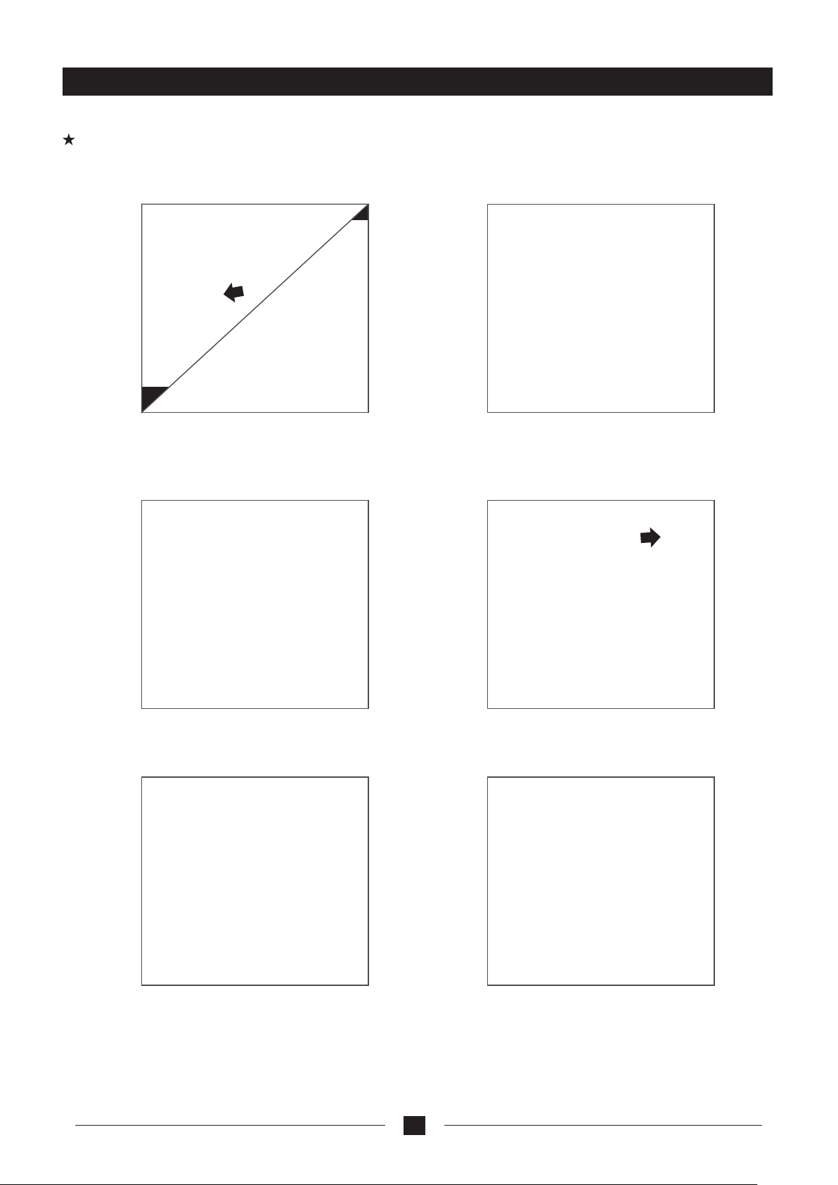
The process of frequency bind for DSSS series 2.4GHz R/C system
Place the transmitter and the receiver close to each other within one (1) meter.
Please do not press the frequency bind switch when the Transmitter at work mode, or else your device will not work!
1. plug the short- circuit plug into the Receiver
in the position of BATT. Connect the ESC to
receiver for electricity supply, which results to
the indicator light glitters.
3. the indicator light of the receiver will light,
which indicates that the frequency bind is
successful.
2. Press the frequency bind button, then
turn on the transmitter' s power.
4. Unplug the short-circuit, the indicator
light glitters.
5. Press frequency bind button again to get it
rebound. After the indicator light flashes for a
few seconds, it turns green, the transmitter
get into working mode.
6. The indicator light turns bright again,
which means that the radio system can
work normally now.
11
Page 14
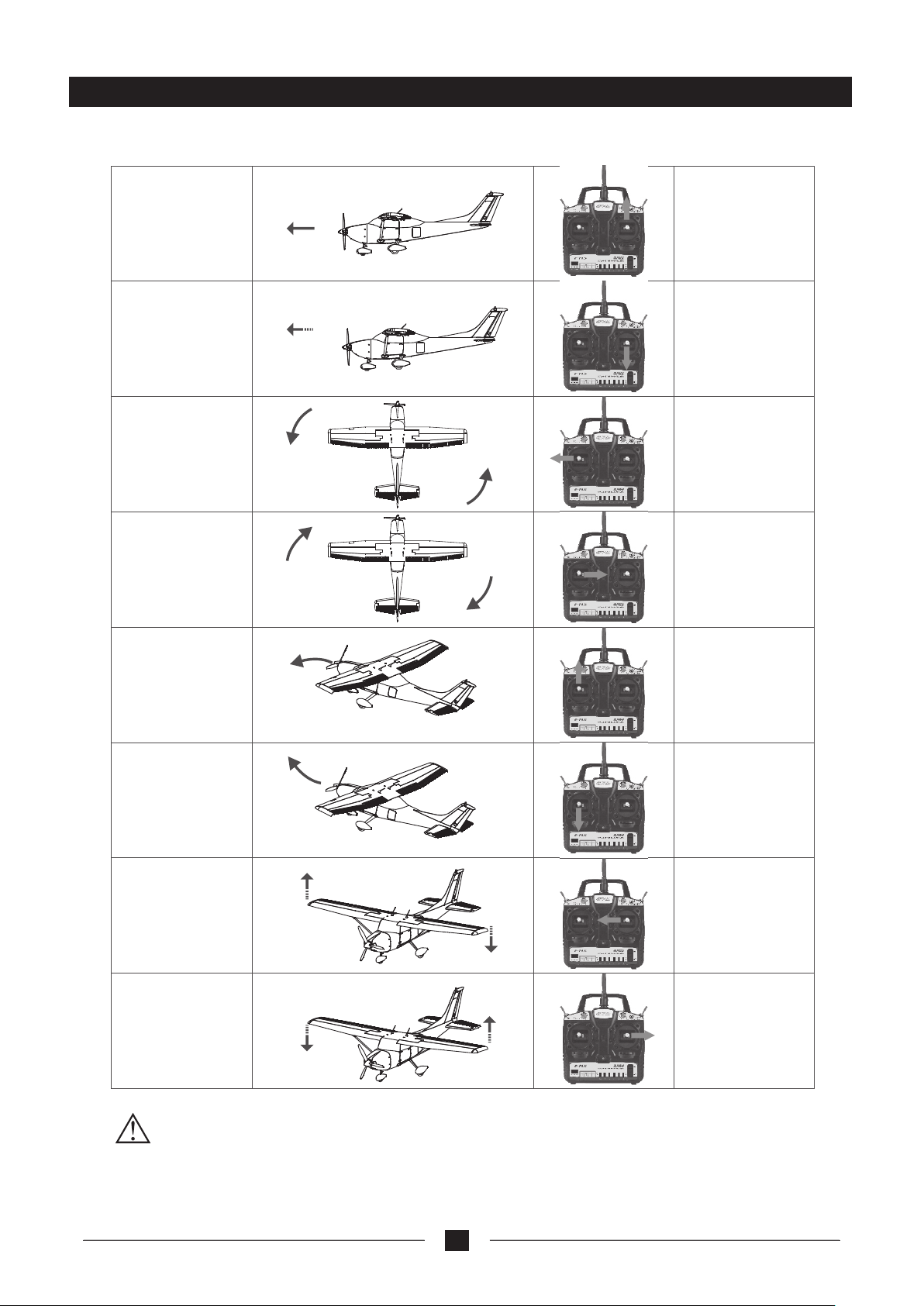
Normal flight
Speed up
Speed down
Nose turn left
Nose turn right
Left stick
pushing up
Left stick
pulling down
Left stick
moving left
Left stick
moving right
nose turn down/
descending
Nose turn up/
ascending
The body incline
to left
The body incline
to right
Right stick
pushing up
Right stick
pulling down
Right stick
moving left
Right stick
moving right
MODE 2 ONLY PLEASE !
12
Page 15
Inspection and adjustment before flying
1. Switch for power supply: Install 8 cel ls i nto the transmitter according to the symb ol o f
battery’s polarity, then turn on the transmitter. Inst al l the full charged flight battery into the ba tt ery
compartment of the fuselage, and conn ec t the plug of battery with the electronic Spe ed C ontroller.
To make sure the radio control system is work in g well, you should follow the instruction : tu rn on the
transmitter before flying (connec ti ng the battery with ESC plug); and turn off the power for receiver
first when stop operation (pulling ou t ba ttery and ESC plug), then turn off the transmitter.
2. The right joystick of tr an smitter controls the aileron by turning l ef t or right: when you push the
joystick on the left, the left aileron of p la ne will turn up and the right aileron of plane will t urn down in
response to your action, vice versa. Be fo re flying, put the trim of aileron to the middl e po sition, and
then adjust the both ailerons to the neutra l position with the clevis.
3 The movement of the left jo ys tick in the transmitter controls the powe r of m otor. When holding the
fuselage of the plane, please keep other ob jects away from the propeller in case of hurtin g people or
damaging the propeller. If you push the left j oystick in the lowest position, the power of th e motor will
cease. Now the motor is on standby. You could check the performance of the motor by p ushing the
joystick up slowly.
4. The up and down of the right joy stick of transmitter controls the movem en t of the elevator. When you
push the joystick down, the elevator of p la ne will be flying up, vice versa. The best state before
flying is the elevator, joysticks and tr im a re all in the neutral position.
5. The left joystick in tra ns mitter control the rudder: when you push th e jo ystick on the right, the
rudder of plane will turn right in response t o your action, vice versa. Rudder, joystick tr im should be
in the middle before flying.
6. If the servos and motor give no response d ur ing the adjustment, please check the connec tion of the
servos and ESC and make sure the battery is f ul ly charged.
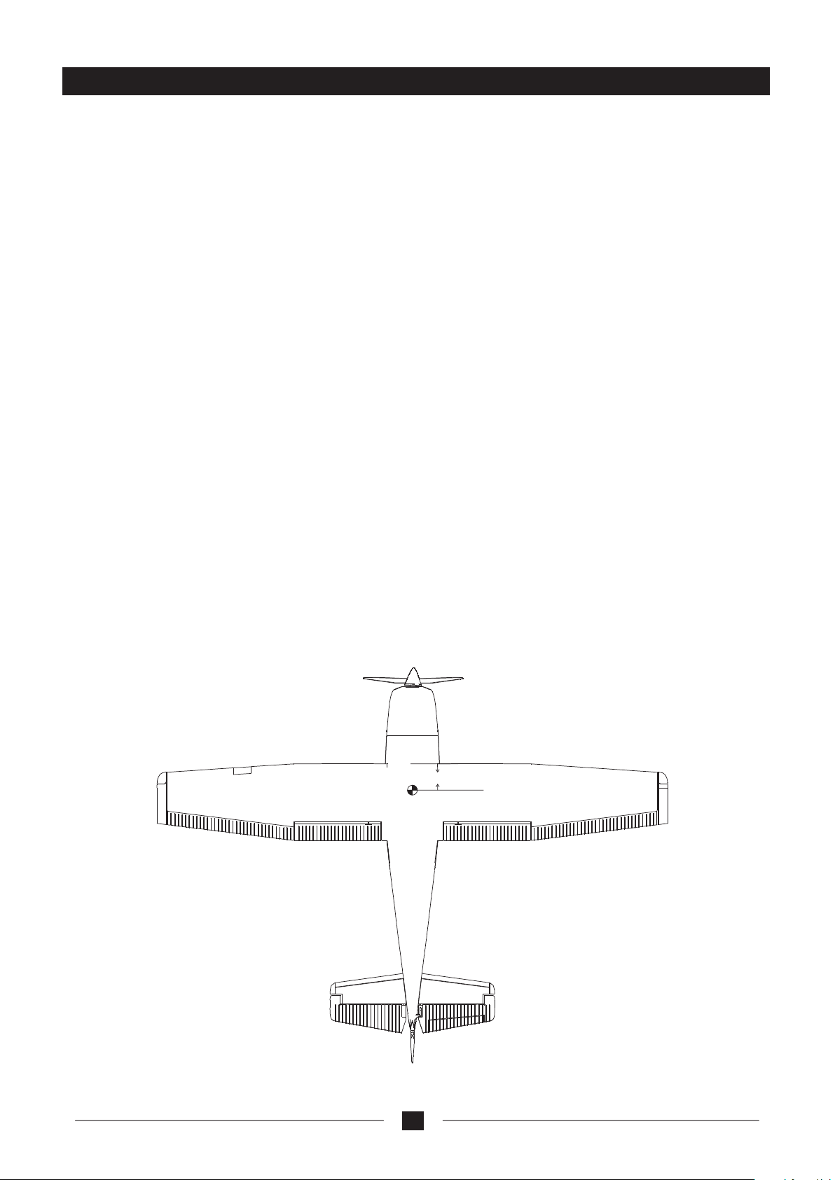
7. Check the CG of the model. The proper CG position should be 6 0~ 70mm away from the leading
edge, please refer to the picture. If in an y do ubt contact your dealer.
Note: The transmitter and receiver sh ou ld be used in the same set but not be mixed and used with
other products.
60~70 m m
(P icture for CG)
13
Page 16

Adjustment during the flying
1. Radio control distance should be tested before flying the aircraft. After loading the battery to the model
and transmitter, turn on the switch and keep the control distance about 200 meters between the transmitter
and the model.
2. Please turn on the transmitter and check the batteries, the indicator should be green. If it is not then replace
the AA cells with new ones.
3. Plug in the power supply, operate the joystick to see whether the movement of the control surface is normal
or not. Push the throttle to the lowest position and push it upwards gradually. The propeller will run very fast,
which causes big thrust and noise. Then the model can fly from the ground after running or you can hand
launch it.
4. If the motor runs slowly or the thrust is not powerful, please do not take off. Check if the battery has been
fully charged, and if there is any problems with the motor or ESC. The power system can be adjusted during
flying to save power and lengthen the flying time, and the recommended method is cruising at around 1/3
power.
5. If you want to land it after flying for some time, pull the throttle stick to the low position and let it land gently.
6. After landing unplug the flight battery and then switch of the transmitter.
7. If the battery voltage becomes to low in the transmitter the indicator will turn RED, if this happens land the
aircraft as soon as possible to avoid losing control of the model.
14
Page 17
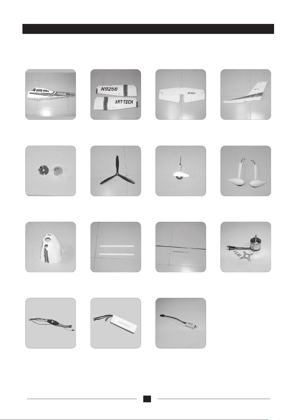
Spare parts list
If you need to do any maintenance or repair of th e Cessna 182 500 Class,
please contact the nearest dealer for the s pare parts.
No.:5 W 0 11
fuselage set
5W051
No.:
spinner
No.:
5W021 No.:
main wing set
5W061
No.:
propeller
horizontal tail plane
No.:
front wheel set
5W031 No.:
5W071
5W041
vertical fin
5W081
No.:
main wheel set
5W091
cowl
No.: 33 0 2 7
30A brushless ESC
No.:
5W101 No.:
wing struts
No.: 3F 0 2 7
Li-po battery
(11.1V 2400mAh)
wing spars
No.: 5Q 0 1 1
servo slowness switch
15
5W111No.:
No.: 3A01 K
motor set( 3 715-01 C )
Page 18

www.art-tech.com
 Loading...