

Page 1

-~
~I
Your
for
ARTISAN
TECHNOLOGY
definitive
quality
equipment.
GROUP
source
pre-owned
®
•
Critical
• In
with
We
along
Custom
so
your
stock/
Full-service,
experienced
buy
your
with
credit
engineering
equipment
and
expedited
Ready-to-ship
independent
engineers
excess,
for
buybacks
works
exactly as
services
repair
and
technicians
underutilized,
and
trade-ins
you
specify.
•
Leasing
•
!TAR-certified
center
and
.
/
Rentals/
on staff.
idle
Demos
secure
equipment
asset
solutions
Artisan Technology
Group
Find the Advanced Energy PDX II at our website: Click HERE
Expert
All
tr
ademarks,
team
br
a
nd
names, a
I
Trust
nd
br
guarantee
a
nd
s a
pp
earing he re
in
are
th
I
100%
e pr operty of
satisfaction
th
e
ir
r
es
pecti
ve
ow
ner
s.
Page 2
Paramount® MF 2 kW Generator
User Manual
January 2018 57020114-00E
Page 3

Advanced Energy
®
Paramount® MF 2 kW Generator
COPYRIGHT
This manual and the information contained herein are the proprietary property of Advanced
Energy Industries, Inc.
No part of this manual may be reproduced or copied without the express written permission of
Advanced Energy Industries, Inc. Any unauthorized use of this manual or its contents is
strictly prohibited. Copyright © 2008-2018 Advanced Energy Industries, Inc. All Rights
Reserved.
DISCLAIMER AND LIMITATION OF LIABILITY
The information contained in this manual is subject to change by Advanced Energy
Industries, Inc. without prior notice. Advanced Energy Industries, Inc. makes no warranty of
any kind whatsoever, either expressed or implied, with respect to the information contained
herein. Advanced Energy Industries, Inc. shall not be liable in damages, of whatever kind, as
a result of the reliance on or use of the information contained herein.
PRODUCT USAGE STATEMENT
WARNING:
Read this entire manual and all other publications pertaining to the work to
be performed before you install, operate, or maintain this equipment. Practice
all plant and product safety instructions and precautions. Failure to follow
instructions can cause personal injury and/or property damage. If the
equipment is used in a manner not specified by the manufacturer, the
protection provided by the equipment might be impaired. All personnel who
work with or who are exposed to this equipment must take precautions to
protect themselves against serious or possibly fatal bodily injury.
Advanced Energy Industries, Inc., (AE) provides information on its products
and associated hazards, but it assumes no responsibility for the after-sale
operation of the equipment or the safety practices of the owner or user.
NEVER DEFEAT INTERLOCKS OR GROUNDS.
TRADEMARKS
All Advanced Energy trademarks are the property of Advanced Energy Industries, Inc. For
the list of Advanced Energy trademarks, visit http://www.advanced-energy.com/en/
Trademarks.html. Any unauthorized use of Advanced Energy trademarks is prohibited.
57020114-00E ii
Page 4

Advanced Energy
®
All other trademarks are the property of their respective owners.
CUSTOMER FEEDBACK
Advanced Energy’s technical writing staff has carefully developed this manual using
research-based document design principles. However, improvement is ongoing, and the
writing staff welcomes and appreciates customer feedback. Please send any comments on the
content, organization, or format of this user manual to:
To order a manual, please contact Technical Support:
Paramount® MF 2 kW Generator
57020114-00E iii
Page 5

Advanced Energy
®
Paramount® MF 2 kW Generator
Table of Contents
Chapter 1. Safety and Product Compliance Guidelines
Important Safety Information ................................................................................. 1-1
Danger, Warning, and Caution Boxes ................................................................... 1-1
Safety Guidelines .................................................................................................. 1-1
Rules for Safe Installation and Operation ....................................................... 1-2
Interpreting Product Labels ................................................................................... 1-2
Product Compliance .............................................................................................. 1-3
Product Certification ................................................................................ ....... 1-3
Safety and EMC Directives and Standards ............................................. ....... 1-3
Conditions of Use .................................................................................... ....... 1-4
Environmental Compliance ............................................................................. 1-4
Interlocks ............................................................................................................... 1-5
Hardware Interlocks and Interlock Circuit ....................................................... 1-5
Chapter 2. Product Overview
Product Description ............................................................................................... 2-1
General Description ........................................................................................ 2-1
Theory of Operation ....................................................................................... ....... 2-1
Operation Overview ........................................................................................ 2-1
Rectifier Module .............................................................................................. 2-2
Inverter Module ............................................................................................... 2-2
Isolation Transformer ...................................................................................... 2-2
Filter ................................................................................................................ 2-2
Directional Coupler/Detector ................................................................... ....... 2-3
Voltage Control Mode ..................................................................................... 2-3
Controls ................................................................................................... ....... 2-3
Power Regulation .................................................................................................. 2-3
Regulation Overview ............................................................................... ....... 2-3
Forward and Reflected Power ................................................................. ....... 2-3
Load Power ............................................................................................. ....... 2-4
Chapter 3. Specifications
Physical Specifications .......................................................................................... 3-1
Electrical Specifications ................................................................................. ....... 3-3
Cooling Specifications ......................................................................................... 3-11
Environmental Specifications .............................................................................. 3-13
Chapter 4. Communication Controls
57020114-00E ivTable of Contents
Page 6

Advanced Energy
®
Paramount® MF 2 kW Generator
25-Pin User Port .................................................................................................... 4-1
25-Pin User Port Connector .................................................................... ....... 4-1
User Port Cabling Requirements .................................................................... 4-1
Satisfying Minimal Requirements for the 25-Pin User Port ..................... ....... 4-1
25-Pin User Port Signal and Pin Descriptions ......................................... ....... 4-2
Wiring Diagrams for the 25-Pin User Port ................................................ 4-6
AE Bus Interface (Host Port) ............................................................................... 4-10
Host Connector ............................................................................................. 4-11
Host Port Pin Descriptions ............................................................................ 4-11
AE Bus Transmission Parameters ................................................................ 4-11
Host Port DIP Switches ........................................................................... ..... 4-12
DIP Switch and Switch Settings ............................................................. 4-12
Switches ................................................................................................. 4-12
Setting the Baud Rate ............................................................................ 4-13
Default Dip Switch Settings .................................................................... 4-13
Setting the Unit AE Bus Address ...................................................... ..... 4-13
AE Bus Protocol ...................................................................................... ..... 4-14
AE Bus Header Byte ......................................................................... ..... 4-15
AE Bus Command Number Byte ...................................................... ..... 4-15
AE Bus Optional Length Byte ........................................................... ..... 4-16
AE Bus Data Bytes ........................................................................... ..... 4-16
AE Bus Checksum Byte ......................................................................... 4-16
Creating an Ideal Communications Transaction ........................................... 4-17
T0: Host Transmits Message Packet ................................................ ..... 4-17
T1: Unit Verifies Host Transmission Packet ........................................... 4-17
T2: Unit Transmits Response to Host ............................................... ..... 4-18
T3: Host Acknowledges Unit Response ................................................. 4-18
AE Bus Communications Transaction Example ............................... ..... 4-18
AE Host Commands ............................................................................................ 4-19
AE Host Command Status Response (CSR) Codes ............................... ..... 4-19
AE Host Command Set ........................................................................... ..... 4-20
Chapter 5. Installation, Setup, and Operation
Preparing to Install the Unit ................................................................................... 5-1
Spacing and Mounting Requirements ..................................................... ....... 5-1
Unit Drawings .......................................................................................... ....... 5-2
Installation Requirements ........................................................................ ....... 5-9
Unpacking the Unit .................................................................................. ..... 5-10
Installing the Unit ................................................................................................. 5-10
Grounding ..................................................................................................... 5-10
Connecting Cooling Water ............................................................................ 5-11
Connecting Output Power ....................................................................... ..... 5-12
Connecting Output Power and Satisfying RF Connector Interlock ... ..... 5-12
Connecting AC Input Power .................................................................... ..... 5-13
Harting AC Power Connector ................................................................. 5-13
To Connect AC Input Power with the Harting Connector ....................... 5-14
Connecting I/O and Auxiliary Connectors ..................................................... 5-15
57020114-00E vTable of Contents
Page 7

Advanced Energy
®
Paramount® MF 2 kW Generator
Connecting For External Voltage Regulation Mode ................................ ..... 5-15
Front Panel Functions ......................................................................................... 5-16
Using the Front Panel to Monitor Unit Status and Unit Operating Data .. ..... 5-16
LED and Numeric Display Behavior When a Fault is Present ...................... 5-17
LED and Numeric Display Behavior When Interlock is Not Satisfied ...... ..... 5-17
Status LED Indicators ................................................................................... 5-17
Generator LEDs ............................................................................................ 5-18
First Time Operation ...................................................................................... ..... 5-19
Command Sequence and Timing Recommendations ......................................... 5-20
Frequency Tuning .......................................................................................... ..... 5-23
Understanding Automatic Tuning and Sweep Frequency ....................... ..... 5-23
RF On Tuning ................................................................................... ..... 5-23
Retuning ................................................................................................. 5-24
Automatic Tuning Parameters ................................................................. ..... 5-25
Pulsing Output ..................................................................................................... 5-27
Understanding Pulsing ............................................................................ ..... 5-27
Pulsing Parameters ................................................................................. ..... 5-28
To Set Up Master/Slave Pulsing ................................................................... 5-28
To Enable/Disable Pulsing and Set Pulsing Parameters .............................. 5-28
Safe Operating Area (SOA) Feature ................................................................... 5-29
Maintenance ........................................................................................................ 5-29
Consumable Parts ................................................................................... ..... 5-29
Chapter 6. Troubleshooting and Global Services
Troubleshooting the Unit ....................................................................................... 6-1
To Troubleshoot an Overtemperature Condition ..................................... ....... 6-2
To Troubleshoot Set Point Problems .............................................................. 6-3
Internal Diagnostics ............................................................................................... 6-3
To Run Internal Diagnostics .................................................................... ....... 6-4
Troubleshooting Using Error Codes ...................................................................... 6-5
Accessing Error Codes ................................................................................... 6-5
Fault and Warning Types and Clearing Faults ........................................ ....... 6-5
Warning and Fault Code Tables ..................................................................... 6-6
Warning Codes ................................................................................. ....... 6-6
Fault Codes .............................................................................................. 6-9
AE Global Services ........................................................................................ ..... 6-14
Returning Units for Repair ................................................................................... 6-16
Purging Water for Transport or Storage .................................................. ..... 6-16
57020114-00E viTable of Contents
Page 8

Advanced Energy
®
Paramount® MF 2 kW Generator
List of Tables
Table 1-1. Hardware interlocks ...................................................................... ....... 1-5
Table 3-1. Physical specifications ......................................................................... 3-1
Table 3-2. Electrical specifications ........................................................................ 3-3
Table 3-3. Cooling specifications ................................................................... ..... 3-11
Table 3-4. Environmental standard specifications ........................................ ..... 3-13
Table 3-5. Climatic specifications ....................................................................... 3-13
Table 4-1. Jumpers on a dummy plug to satisfy minimal signal
requirements .................................................................................................
Table 4-2. User port signal descriptions ................................................................ 4-2
Table 4-3. 25-pin User port pin descriptions ................................................. ....... 4-3
Table 4-4. Host port pin descriptions ............................................................. ..... 4-11
Table 4-5. DIP switch settings for variable baud rate, switches 6 and 7 ............. 4-13
Table 4-6. Default dip switch settings ............................................................ ..... 4-13
Table 4-7. AE Bus address settings .................................................................... 4-13
Table 4-8. AE Bus byte structure ................................................................... ..... 4-16
Table 4-9. AE Host command status response (CSR) codes ........................ ..... 4-19
Table 4-10. AE Host commands .................................................................... ..... 4-20
Table 5-1. HARTING 70 A connector pin descriptions ........................................ 5-13
Table 5-2. HARTING 70 A connector part numbers ...................................... ..... 5-14
Table 5-3. I/O and auxiliary ports ........................................................................ 5-15
Table 5-4. Status LED indicators ................................................................... ..... 5-17
Table 5-5. Generator LEDs ................................................................................. 5-18
Table 5-6. Recommended command sequence and timing ................................ 5-21
Table 5-7. Frequency tuning parameters ............................................................ 5-25
Table 5-8. Pulsing parameters ............................................................................ 5-28
Table 6-1. Warning codes ..................................................................................... 6-6
Table 6-2. Fault codes ................................................................................... ....... 6-9
Table 6-3. AE Global Services 24 X 7 contact information ............................ ..... 6-15
....... 4-2
57020114-00E viiList of Tables
Page 9

Advanced Energy
®
Paramount® MF 2 kW Generator
List of Figures
Figure 1-1. Interlock circuit .................................................................................... 1-6
Figure 2-1. Paramount MF 2 kW generator block diagram ............................ ....... 2-2
Figure 3-1. Timing diagram ................................................................................... 3-9
Figure 3-2. Pressure drop .............................................................................. ..... 3-12
Figure 4-1. User port connector, 25-pin ......................................................... ....... 4-1
Figure 4-2. REFL PWR MONITOR (pins 2 and 15) ....................................... ....... 4-6
Figure 4-3. FWD/LOAD PWR MONITOR (pins 3 and 16) ............................. ....... 4-7
Figure 4-4. RF PWR ON (pins 4 and 17) ....................................................... ....... 4-7
Figure 4-5. SET POINT (pins 5 and 18) ................................................................ 4-7
Figure 4-6. DC BIAS/POWER REGULATION (pins 6 and 19) ...................... ....... 4-8
Figure 4-7. FWD/LOAD PWR REGULATION (pins 8 and 21) ....................... ....... 4-8
Figure 4-8. INTERLOCK LOOP (pins 23 and 10) .......................................... ....... 4-9
Figure 4-9. +15 VDC (pins 13 and 21) ........................................................... ....... 4-9
Figure 4-10. SET POINT STATUS (pins 14 and 1) ............................................... 4-9
Figure 4-11. OVERTEMP (pins 22 and 9) ........................................................... 4-10
Figure 4-12. DC BUS OK (pins 24 and 11) ......................................................... 4-10
Figure 4-13. Host port connector ................................................................... ..... 4-11
Figure 4-14. Slide DIP switch .............................................................................. 4-12
Figure 4-15. Graphic representation of a message packet ............................ ..... 4-15
Figure 4-16. AE Bus communications transaction ......................................... ..... 4-17
Figure 4-17. Communications transaction example ............................................ 4-19
Figure 5-1. Front panel .......................................................................................... 5-2
Figure 5-2. Rear panel ................................................................................... ....... 5-3
Figure 5-3. Rear panel with dimensions ................................................................ 5-4
Figure 5-4. Rear panel three dimensional ............................................................. 5-5
Figure 5-5. Left side ....................................................................................... ....... 5-6
Figure 5-6. Right side ............................................................................................ 5-7
Figure 5-7. Top side .............................................................................................. 5-8
Figure 5-8. Bottom side ......................................................................................... 5-9
Figure 5-9. RF output connector, HN coaxial, female (TRU-8371-SNT) ............. 5-12
Figure 5-10. HARTING AC 70 A power input connector on back of unit ....... ..... 5-13
Figure 5-11. Front panel display with Status and Generator LEDs ..................... 5-16
57020114-00E viiiList of Figures
Page 10
Paramount
®
MF 2 kW Generator
Chapter
Safety and Product Compliance
Guidelines
IMPORTANT SAFETY INFORMATION
To ensure safe installation and operation of the Advanced Energy Paramount MF 2
kW unit, read and understand this manual before attempting to install and operate this
unit. At a minimum, read and follow the safety guidelines, instructions, and practices.
DANGER, WARNING, AND CAUTION BOXES
1
This symbol represents important notes concerning potential harm to people, this
unit, or associated equipment. Advanced Energy includes this symbol in danger,
warning, and caution boxes to identify specific levels of hazard seriousness.
DANGER:
DANGER indicates an imminently hazardous situation that, if not avoided,
will result in death or serious injury. DANGER is limited to the most extreme
situations.
WARNING:
WARNING indicates a potentially hazardous situation that, if not avoided,
could result in death or serious injury, and/or property damage.
CAUTION:
CAUTION indicates a potentially hazardous situation that, if not avoided,
could result in minor or moderate injury, and/or property damage. CAUTION
is also used for property-damage-only accidents.
SAFETY GUIDELINES
Review the following information before attempting to install and operate the
product.
57020114-00E Safety and Product Compliance Guidelines 1‑1
Page 11
Advanced Energy
®
Paramount® MF 2 kW Generator
Rules for Safe Installation and Operation
Please note the following rules:
• Do not attempt to install or operate this equipment without proper training.
• Ensure that this unit is properly grounded.
• Ensure that all cables are properly connected.
• Verify that input voltage and current capacity are within specifications before
turning on the power supplies.
• Use proper electrostatic discharge (ESD) precautions.
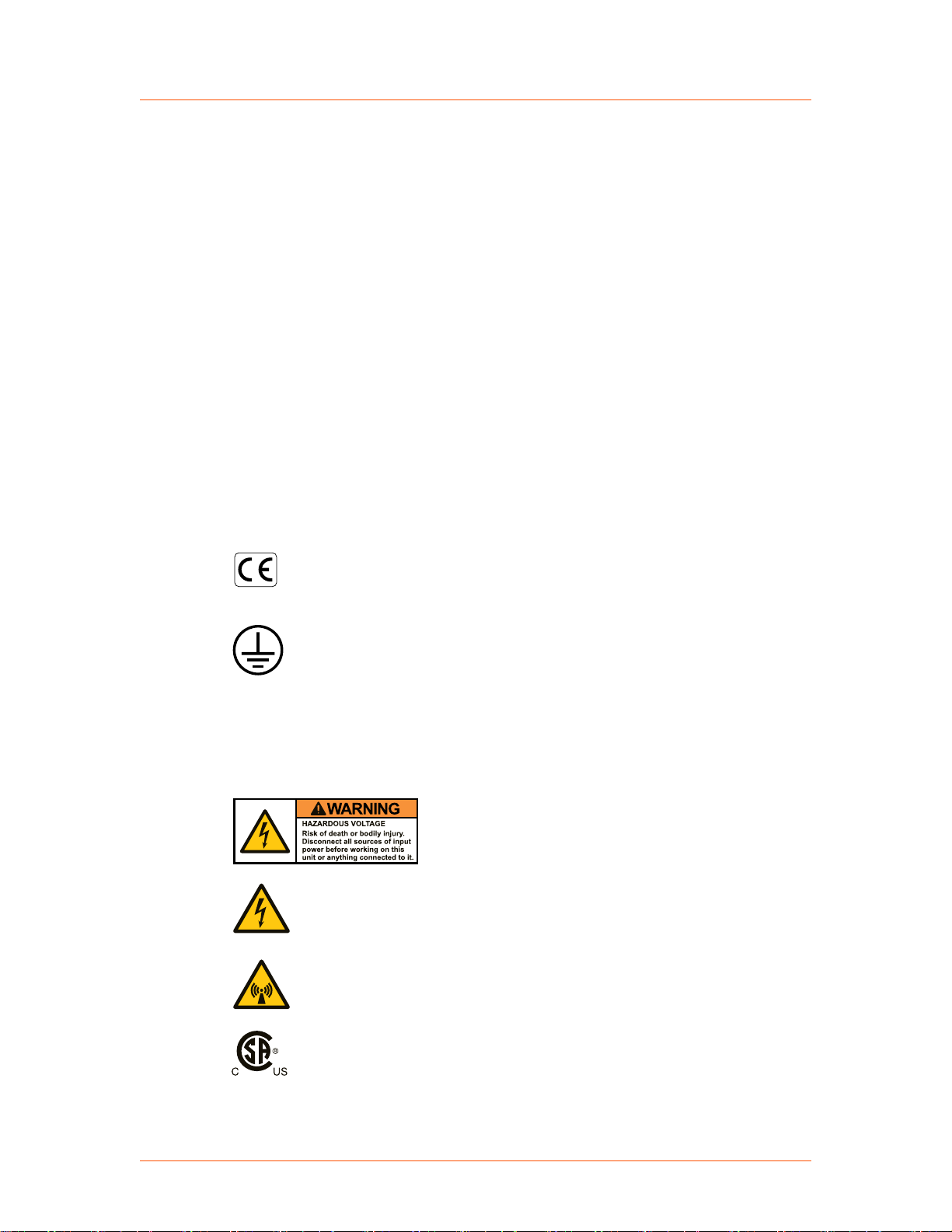
INTERPRETING PRODUCT LABELS
The following labels may appear on your unit:
CE label
Complies with applicable European
directives.
Protective conductor terminal
This terminal must be connected first and
be of proper type and size for the circuit
with the highest voltage and current
carrying capacity. Note that other
connections may have higher
requirements than that of the MAINS
connection.
Hazardous voltage
Hazardous voltage
Voltage > 30 V
60 VDC
Nonionizing radiation
Radio Frequency emissions may be
harmful.
Certified by CSA to North American
Safety Standards for both Canada and the
United States
, 42.4 V peak, or
rms
57020114-00E Safety and Product Compliance Guidelines 1‑2
Page 12

Advanced Energy
®
PRODUCT COMPLIANCE
Paramount® MF 2 kW Generator
Refer to manual for more information
SEMI® F47 compliant
Heavy object—can cause muscle strain
or back injury
Environmentally Friendly Use Period of
25 years per China RoHS—recycle
responsibly at end of life
The following sections include information about unit compliance and certification,
including the conditions of use required to be in compliance with the standards and
directives.
Product Certification
Certain options of this product may be certified according to the list below.
For more information, refer to the Certificate or Letter of Conformity (US) or
Declaration of Conformity (EU) accompanying the product.
• NRTL – Safety certified by CSA International, a Nationally Recognized Testing
Laboratory
• CE Marking – Self-declaration, assessed by AE Corporate Compliance
• EMC measurements – Verified by AE Corporate Compliance
• SEMI guidelines – Verified by AE Corporate Compliance
Safety and EMC Directives and Standards
For information concerning compliance to applicable EU requirements, refer to the
EU Declaration of Conformity for this unit. The Declaration of Conformity may also
include a supplementary section covering compliance to non-EU regulatory
requirements and/or industry standards or guidelines.
57020114-00E Safety and Product Compliance Guidelines 1‑3
Page 13

Advanced Energy
®
Conditions of Use
To comply with the stated directives and standards, you must meet the following
conditions of use:
• For corner-grounded delta configuration installation, excessive leakage occurs.
Secondary Protective Earth (ground) must be connected.
• The AC power cordset used must comply with local codes and regulations.
• Before making any other connection to this product, connect the primary
Protective Earth (ground), and secondary Protective Earth (ground) if
applicable, to a local earth ground using wire that is sized according to the
applicable requirements.
• To prevent condensation, install and operate this device with an external water
solenoid valve so that water flow is interrupted when the device is not
operating.
• Install and operate this unit in an overvoltage category according to
environmental specifications.
Paramount® MF 2 kW Generator
• Install and operate this unit in a pollution degree environment according to
environmental specifications.
• Operate this device within the ambient temperature and water specifications
declared in the specifications.
• If this unit does not have a circuit breaker, you must install and operate it with a
circuit breaker switch on the AC input. The circuit breaker switch must be
easily accessible and near the unit. The circuit breaker must be marked as the
disconnecting device for the equipment.
• You must install and operate this device with a disconnect switch that conforms
to the applicable requirements. The switch must be easily accessible and near
the device.
• Use only a shielded cable for the input power connections.
• Use only a shielded cable for the output process power connections.
• Use only a shielded cable for communications and/or control connections.
Environmental Compliance
• EU REACH – European Union Regulation (EC) No. 1907/2006
Registration, Evaluation, Authorization and Restriction of Chemicals
Advanced Energy manufactures articles subject to Article 33 of REACH and,
upon request, will provide information regarding Substances of Very High
Concern (SVHC) currently identified by the European Chemical Agency
(ECHA) that are contained in this product, at concentrations greater than 0.1%
by weight.
57020114-00E Safety and Product Compliance Guidelines 1‑4
Page 14
Advanced Energy
®
• China RoHS - People’s Republic of China (PRC) Ministry of Industry and
Information Technology (MIIT) Order #32 (China RoHS 2)
Management Methods for the Restriction of the Use of Hazardous Substances
Electrical and Electronic Products
This product contains hazardous substances listed in PRC Standard GB/T
26572, above the maximum concentration limits stipulated. In compliance to
PRC Standard SJ/T 11364, AE provides a disclosure of hazardous substance
content and this product is marked with an Environmentally Friendly Use
Period (EFUP) of 25 years.
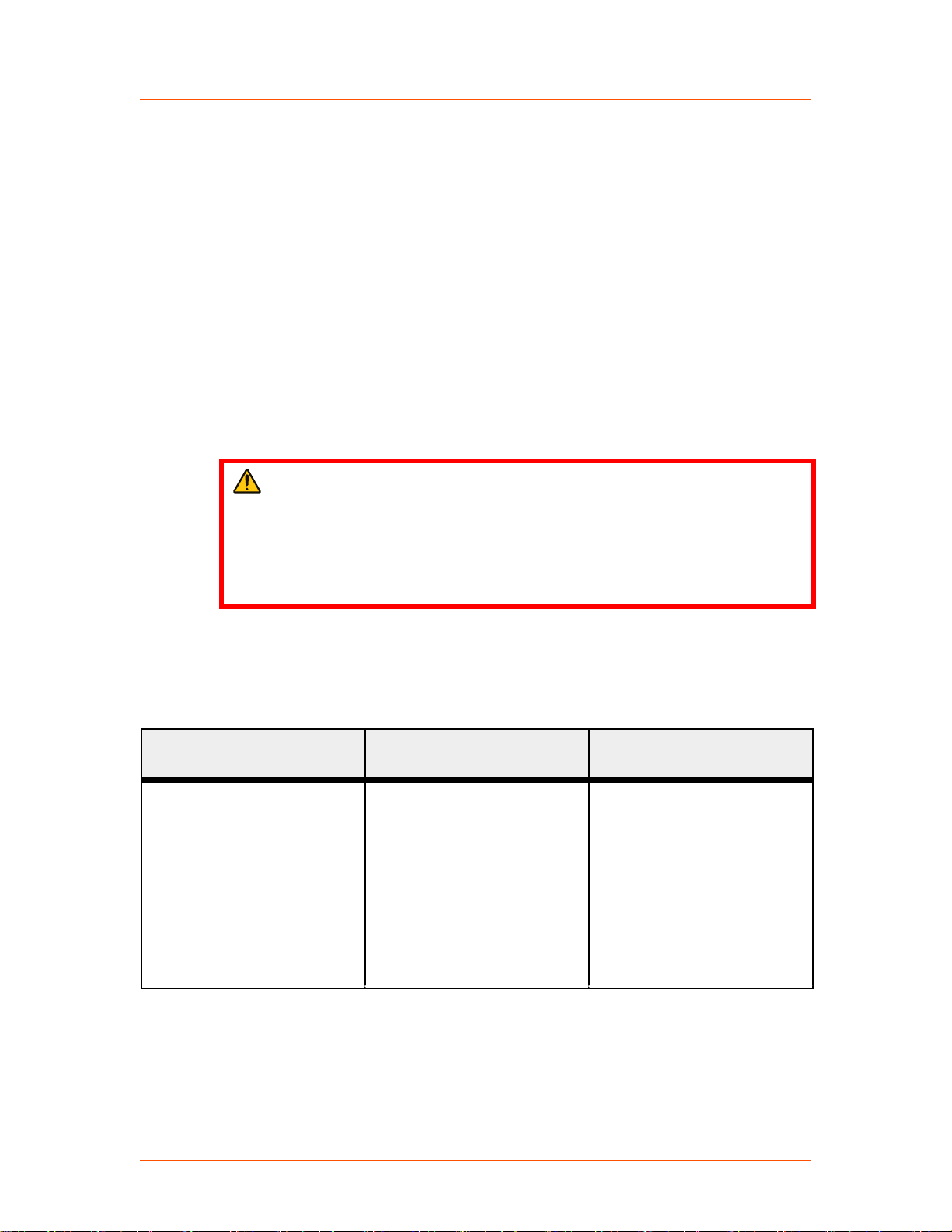
INTERLOCKS
WARNING:
Advanced Energy products only include interlocks when required by product
specification. Interlocks in Advanced Energy products are not intended to
meet or satisfy safety requirements. Where interlocks exist, you must still
meet and satisfy safety requirements. The presence of interlocks does not
imply operator protection.
Paramount® MF 2 kW Generator
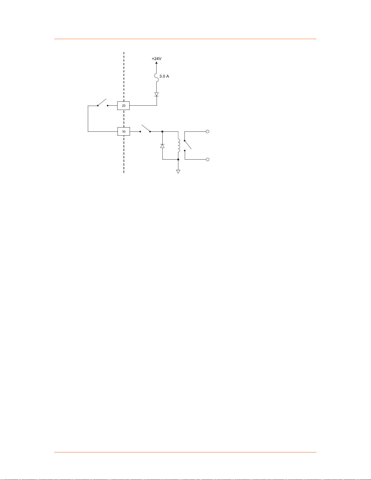
Hardware Interlocks and Interlock Circuit
Table 1‑1. Hardware interlocks
Mechanism Detection Method Equipment Condition When
Interlock relay disables DC
power to the gate drivers of
the RF section, which results
in RF output being disabled.
An interlock condition occurs
when:
• The User port interlock
circuit is not satisfied
• The RF output interlock
switch detects when the
RF cable is not fully
attached.
Interlock is Open
Green Interlock LED is not
lit, interlock is not satisfied,
and as a result RF out cannot
be enabled.
57020114-00E Safety and Product Compliance Guidelines 1‑5
Page 15
User Unit
Interlock
Interlock return
Cable interlock
Interlock relay
Advanced Energy
Figure 1‑1. Interlock circuit
®
Paramount® MF 2 kW Generator
57020114-00E Safety and Product Compliance Guidelines 1‑6
Page 16

Paramount
®
MF 2 kW Generator
Chapter
Product Overview
PRODUCT DESCRIPTION
General Description
The Advanced Energy Paramount MF 2 kW generator is a 360 kHz to 440 kHz
midfrequency generator designed to regulate on one of the following:
• Forward power
• Load power
• Voltage with an optional AE peak voltage sensor
The Paramount MF 2 kW generator provides up to 2000 W into a 50 Ω, nonreactive
load. The generator is capable of delivering 100% of its rated power into a 4.79:1
VSWR load, making it an ideal choice for applications with a fixed match.
2
The Paramount MF 2 kW generators incorporate Direct Digital Synthesis (DDS)
technology for control of the operating frequency. This technology can be useful
when the application requires that the selected generator operate into an impedance
mismatch. The frequency can be programmed to dither over a predetermined range to
minimize the load mismatch to the generator. The DDS operating parameters on each
generator are configured via the generator's serial communications interface and are
stored indefinitely in nonvolatile RAM.
The Paramount MF 2 kW generators are water and air cooled, 7" high, 19" rackmountable units. Front panels with numeric displays and six status LEDs provide
basic generator monitoring. Primary control is accomplished through the generator's
serial and user communications interfaces.
THEORY OF OPERATION
Operation Overview
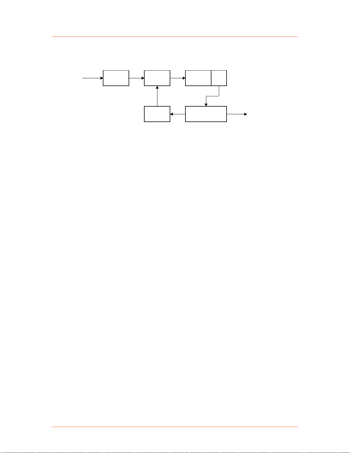
The Paramount MF 2 kW generator efficiently creates sinusoidal voltage waveforms
by switching rectified DC power through a filter and an isolation transformer. A
directional coupler/detector samples the RF power signal and uses the signal to
control the switch waveforms and therefore, the output power. Depending upon the
method of regulation, either the forward or load power can be used as a control
57020114-00E Product Overview 2‑1
Page 17
Isolation
Transformer
Filter
Directional Coupler/
Detector
Mid-frequency
Out
AC
In
Rectifier
Module
Inverter
Module
Controls
3726
Advanced Energy
®
signal. The Paramount MF 2 kW generator can also control the voltage at the load
with proper voltage feedback and setting the unit to voltage control mode.
Figure 2‑1. Paramount MF 2 kW generator block diagram
Rectifier Module
The full-wave bridge rectifier converts the AC input voltage into a steady DC signal.
This power is provided directly into the inverter module.
Paramount® MF 2 kW Generator
Inverter Module
The inverter module is composed of a set of MOSFETs which are either fully on or
fully off. When the FETs are on, very little voltage drop occurs across them. When
they are off, virtually no current flows through them. Since the power dissipated in a
FET is the product of the voltage across and the current through the device, neither
case represents a large power loss. This makes the generator very efficient.
Isolation Transformer
The inverter module produces a waveform with substantial energy at the fundamental
switching frequency, which is set to the desired output frequency. This waveform
goes to the isolation transformer.
The isolation transformer isolates RF output of the generator from the inverter
module which is directly connected to the AC power line. The transformer also
transforms the impedance to bring the output impedance of the generator to a
standard 50 Ω level.
Filter
The filter is a combination of inductors and capacitors especially designed to pass
only the frequency of interest and reject high frequency harmonics (a lowpass filter).
The output of the filter is nearly a perfect sine wave. This wave is then delivered to
the directional coupler/detector.
57020114-00E Product Overview 2‑2
Page 18

Advanced Energy
®
Directional Coupler/Detector
The directional coupler/detector samples the voltage and current of the RF power line
and a digital signal processor (DSP) is used to calculate the forward and reflected
power. The forward and reflected power can be thought of as the power flowing
toward the load and the power reflected back from the load. Forward power minus
reflected power is the power dissipated in the load and is called the load power. The
DSP uses the calculated values in the feedback control loop to control the power
supply output.
The Paramount MF 2 kW generator uses sophisticated signal processing to
compensate for or eliminate offsets and nonlinearities inherent in the generator. As a
result, the output power of the generator is accurate and linear. Forward, reflected,
and load power levels are displayed on the front panel and are provided to, or can be
accessed through, the generator's serial and user communication ports.
Voltage Control Mode
The Paramount MF 2 kW generator has the capability to control the amplitude of RF
output voltage at the load with the use of the AE Low Frequency Fixed Match and
voltage peak detector. The voltage from the peak detector is supplied to the generator
and used to control the inverter.
Paramount® MF 2 kW Generator
Controls
The control section controls the inverter that regulates the output power. This section
has limits and trip thresholds that prevent inverter failure.
POWER REGULATION
Regulation Overview
The Paramount MF 2 kW generator can regulate power based on either forward or
load power measurements. The method used by the generator is determined by User
port pin 8, referenced to pin 21 (FWD/LOAD POWER REGULATION). You can also
use command 3, set regulation mode, at the Host port to select the regulation mode.
The front panel display screen allows you to view operating data for forward,
reflected, and load power parameters.
Forward and Reflected Power
In a mismatched system, the load impedance does not match the connecting cable
impedance, which means there will always be a standing wave on the connecting
cable. Think of this standing wave as being created by the interference of two
57020114-00E Product Overview 2‑3
Page 19

Advanced Energy
travelling waves, one moving toward the load and one returning to the generator. The
power in the imagined wave moving toward the load is the forward power, and the
power in the imagined return wave is the reverse, or reflected, power.
Mathematically, in a system with a reference (cable) impedance Z0, forward and
reflected voltages (V
The plus sign is used for forward voltage and current and the minus sign is used for
reflected voltage and current. The forward and reflected powers are the product of the
voltages and currents:
®
) and current (I
f/r
) can be defined as:
f/r
Paramount® MF 2 kW Generator
Neither the forward nor the reflected power directly determine the process results.
Load Power
The load power is the power actually dissipated in the load. If the load is not reactive,
the load power is simply the voltage times the current. If the load is reactive, there
will be phase angle between the voltage and current, and the load power will be equal
to: V * I * cos (phase angle).
In terms of forward and reflected power, the load power is the forward power minus
the reflected power. Generally, the important factor in a process is the load power,
because by definition that is the actual power delivered to the load.
57020114-00E Product Overview 2‑4
Page 20

Paramount® MF 2 kW Generator
Chapter
Specifications
PHYSICAL SPECIFICATIONS
Table 3‑1. Physical specifications
Description Specification
Size 178 mm (H) x 434 mm (W) x 501 mm (D)
7″ (H) x 17.1″ (W) x 19.7″ (D)
☞ Important
These measurements do not include handles,
connectors, and switches.
Weight 35.38 kg (78 lb) maximum
3
Mounting Standard 19″ rack; optional custom mounting
Clearance A clearance of 13 mm (0.5″) minimum is required at the right
side of the unit for proper cooling.
A clearance of 102 mm (4″) is required at the rear of the unit
for connections.
Connectors/Cable Specifications
RF output connector HN coaxial female (TRU-8371-SNT). Connector has an
interlock which engages when output cable is fully connected.
AC power input
User port connector 25-pin subminiature-D, female
Host port connector 9-pin subminiature-D, female
E-Net port Reserved for AE use only
Pulse In connector SMA
Pulse Out connector SMA
HARTING Han® Modular, 4-pin, 70 A male connector:
• Frame: 09140060303
• Housing: 09300060301
• Insert (70 A): 09140022642
Bias voltage input
Sense V-In connector
Scaled analog output for bias
compensation
57020114-00E Specifications 3‑1
SMA
SMA
Page 21
Advanced Energy
®
Table 3‑1. Physical specifications (Continued)
Description Specification
Bias V-Out connector
Paramount® MF 2 kW Generator
Coolant connectors (water in
SS female Swagelok® 3/8″ on nickel plated brass panel
and water out)
Chassis ground terminal 10-32 stud with nut and star washer
57020114-00E Specifications 3‑2
Page 22

Advanced Energy
®
Paramount® MF 2 kW Generator
ELECTRICAL SPECIFICATIONS
☞ Important
AE Host command 7 restores all nonvolatile RAM values to factory preset
values. See individual product specifications for factory default parameters.
For more information, contact AE Global Services.
Table 3‑2. Electrical specifications
Description Specification
Input Power
Standard operation • Nominal: VAC = 208 V, 60 Hz; Low line AC: VAC = 187 V,
60 Hz
• Output power = 2000 W
• Frequency = 400 kHz
• Load = 50 Ω
AC facility requirements
• Line voltage
• Line frequency
• Phase
AC to RF efficiency Nominal: 78%
AC input power factor Nominal: 0.67
AC power consumption Nominal: 2556 W
AC line current < 16 A
Facility requirements specification:
• Line voltage: 208 VAC ± 10% (187 VAC to 229 VAC)
• Line frequency: 50 Hz to 60 Hz nominal (47 Hz to 63 Hz)
• Phase: 3φ with ground, no neutral
Low line AC: 79%
Low line AC: 0.69
Low line AC: 2514 W
per phase at 2000 W, 208 VAC
RMS
< 18 A
per phase at 2000 W, low AC line
RMS
Overcurrent protection 50 A circuit breaker with lockout pin
RF Output Power
Warm-up time Generator minimum warm-up time of 2 minutes after AC on
Frequency tuning range 360 kHz to 440 kHz
Frequency stability < 50 ppm of selected frequency
57020114-00E Specifications 3‑3
Page 23

Advanced Energy
®
Table 3‑2. Electrical specifications (Continued)
Description Specification
Reflected power limit 1500 W maximum
Paramount® MF 2 kW Generator
Delivered power into
mismatched loads
(Automatic load
Generator maximum delivered power is based on reflected power
limit.
• Within VSWR 1.1:1 it is 2000 W
mismatch protection,
unlimited load impedance
range, full frequency
• Within VSWR 2.0:1 it is 2000 W
• Within VSWR 4.79:1 it is 2000 W
range)
• Outside VSWR 4.79:1, maximum delivered power is restricted
Delivered power setpoint
5 W to 2000 W
range
Frequency resolution 1 Hz
Regulation modes
Regulation modes:
selected by tool interface
• Forward power regulation mode
• Load power regulation mode
• Voltage regulation mode
Measured power accuracy
in full frequency range
and across full line
voltage range
Measured power accuracy is a combination of the generator and
measurement equipment accuracy.
These specifications were created per an AE test measurement
procedure. Using alternate test measurement devices and/or
procedures will result in deviations from the provided numbers and
values listed in this specification.
by reflected power limit, 1500 W.
Measured power accuracy
Power accuracy:
into 50 Ω non-reactive
load
• ± 0.5 W of setpoint for 5 W to 50 W
• ± 1% of setpoint or ± 2 W, whichever is greater, when
operating at 400 kHz, into a 50 Ω, non-reactive load for 50 W
to 2000 W
• ± 1.5% of setpoint or ± 2 W, whichever is greater, over entire
frequency range when operated into a 50 Ω, non-reactive load,
for 50 W to 2000 W
Measured power accuracy
Power accuracy:
into 2:1 VSWR circle
• ± 1.5 W of setpoint for 5 W to 50 W, over entire frequency
range
• ± 2.5% of setpoint or ± 2 W for 50 W to 2000 W, whichever is
greater, over entire frequency range
57020114-00E Specifications 3‑4
Page 24

Advanced Energy
®
Table 3‑2. Electrical specifications (Continued)
Description Specification
Paramount® MF 2 kW Generator
Measured power accuracy
into 4.79:1 VSWR circle
Repeatability (same
generator) over the full
frequency and power
range into 50 Ω nonreactive load
Repeatability generatorto-generator over the full
frequency and power
range into 50 Ω nonreactive load
Load mismatch stability
over full frequency and
power range
Power accuracy:
• ± 2 W of setpoint for 5 W to 50 W, over entire frequency range
• ± 3.5% of setpoint or ± 2 W for 50 W to 2000 W, whichever is
greater, over entire frequency range
Same generator repeatability:
• ± 1 W of setpoint for 5 W to 50 W
• ± 1% of setpoint or ± 1.5 W, whichever is greater, when
operating at 400 kHz, into a 50 Ω, nonreactive load for 50 W
to 2000 W
• ± 1.5% of setpoint or ± 2 W, whichever is greater, over entire
frequency range when operated into a 50 Ω, nonreactive load,
for 50 W to 2000 W
< 2.0% or 4 W, whichever is greater, from 50 W to 2000 W into a
50 Ω, non-reactive load
The generator will operate continuously into any load impedance
without failure.
Short term output power
drift operating into a 50 Ω
load
< 1.0% during one continuous hour of operation beginning with a
setpoint of 0 W at 400 kHz and giving the generator a 2000 W
setpoint operating into a 50 Ω load.
RF on/off response time Analog User interface:
• RF rise time: < 20 ms from leading edge of RF ENABLE signal
to 81% of setpoint (90% of the output voltage) provided a
single command received by the generator. No overshoot.
• RF fall time: < 6 ms from falling edge of RF ENABLE signal
to < 5 W provided a single command received by the
generator.
RF on/off response time Serial Host interface:
• RF rise time: < 20 ms upon receipt of AE Bus command to
81% of setpoint provided a single command received by the
generator. No overshoot.
• RF fall time: < 6 ms upon receipt of AE Bus command to <
5 W provided a single command received by the generator.
57020114-00E Specifications 3‑5
Page 25

Advanced Energy
®
Table 3‑2. Electrical specifications (Continued)
Description Specification
Paramount® MF 2 kW Generator
Setpoint change response
time
Analog User interface
Setpoint change response
time
Serial Host interface
Spurious signals in full
frequency and power
range on 50 Ω load
Harmonics in full
frequency range at
maximum power on 50 Ω
load
Analog response time is measured from step setpoint change to
90% change of the RF output voltage.
• RF rise time < 30 ms over full power range into a broadband
load
• RF fall time < 30 ms over full power range into a broadband
load
Serial interface response time is measured upon receipt of an AE
Bus command to 90% change of the output RF voltage.
• RF rise time < 25 ms over full power range into a broadband
load
• RF fall time < 25 ms over full power range into a broadband
load
- 50 dBc
- 30 dBc
Maximum allowable
50 W minimum between 2 MHz and 300 MHz
forward power incident
upon the RF outputs from
external sources/ load
Zero/Low setpoint RF output is disabled if setpoint in power control mode is less than
5 W. RF output is disabled if setpoint in external voltage control
mode is less than 20 V. RF ON LED on the front panel remains on.
RF ramp rate control The rise and fall rate of the RF output can be programmed via the
serial Host interface. This function is enabled for RF ON and
setpoint up or down changes via the serial Host interface.
For safety reasons, an RF OFF command will not ramp down the
output. The rate can be defined in watts per second or absolute time
through the serial Host interface.
Watts per second mode can be set in 1 W increments.
Absolute time mode range in 1 ms increments:
• Minimum ramp time: 1 ms
• Maximum ramp time: 30000 ms
The ramp rate parameters are not allowed to change while a setpoint
ramp is currently in progress.
57020114-00E Specifications 3‑6
Page 26
Advanced Energy
®
Paramount® MF 2 kW Generator
Table 3‑2. Electrical specifications (Continued)
Description Specification
Diagnostics The generator will evaluate its internal parameters for the relative
health of the generator. Special diagnostic capability is provided for
testing into short (0 Ω) load.
Tuning Algorithm
The unit is designed and programmed to utilize a sweep frequency algorithm to optimize power
delivery and minimize load mismatch as detected by the unit's output sensor. The algorithm is
able to:
• Minimize load mismatch
• Lock the generator at a tune point
• Track (re-tune) frequency to follow changes in load impedance to minimize load mismatch
Frequency tuning range 360.1 kHz to 439.6 kHz
Frequency preset: Start
360.1 kHz to 439.6 kHz, 1 kHz resolution
minimum and maximum
frequency
Tune time < 0.1 second from RF enabled at a preset frequency (within 10% or
2 W of the minimum reflected power, whichever is greater)
Typical tune time for
60 ms tuning delay +25 ms tuning
factory set tuning
parameters
Tracking and re-tune < 0.1 s maximum
If load mismatch increases above a user defined threshold, the
generator will re-tune.
Tuned frequency
± 2 kHz
repeatability
Pulsing into Broadband 50 Ω
Frequency range 10 Hz to 2 kHz (minimum on width has to be satisfied)
Duty cycle range 10% to 90% (minimum on width has to be satisfied)
Minimum on width 225 μs
Rise/ fall time When output voltage reaches 67% of nominal:
• Rise time 10 μs maximum
• Fall time 10 μs maximum
Settling time When output voltage settles within 10% of nominal:
• 300 μs at 5 W output power
• 30 μs at 2000 W output power
Voltage overshoot With a 50 Ω broadband load:
57020114-00E Specifications 3‑7
Page 27
Advanced Energy
®
Paramount® MF 2 kW Generator
Table 3‑2. Electrical specifications (Continued)
Description Specification
• Maximum 25%
Power accuracy Pulse power level is the same as CW after pulse settling time.
Pulse to pulse jitter Pulse length uncertainty (pulses can be longer than programmed):
Maximum 1 RF period (2.5 μs at 400 kHz)
Synchronization Start of pulse is synchronized to the phase of the RF clock.
Pulsing into non 50 Ω Loads
Load is a fixed matching network loaded to the "plasma model", which is 30 Ω to 116 Ω resistor
in series with 1.1 nF capacitor.
Minimum on width 225 μs
Settling time Less than 500 μs
Voltage overshoot x 6 times (typical)
Pulse Sync In/Out
Frequency range 10 Hz to 2 kHz
Minimum on width must be satisfied.
Duty cycle 10% to 90%
Minimum on width must be satisfied.
Minimum on width 225 μs
Pulse Sync In RF pulse on high level
Z = 50 Ω
0 VDC to 5 VDC maximum
Pulse Sync Out RF pulse on high level
Z = 50 Ω source impedance
0 VDC to 5 VDC unloaded
0 VDC to 2.5 VDC across a 50 Ω load
Pulsed output timing
1.0 μs edge uncertainty
accuracy
RF Voltage/Power Detection Sampling
Sample delay 150 μs
Sample rate 36 μs sampling rate of voltage in voltage control mode
16 μs sampling rate of power in power control mode
Averaging Control loop--averaging by integrator, readback--Moving average
of 8 samples
57020114-00E Specifications 3‑8
Page 28
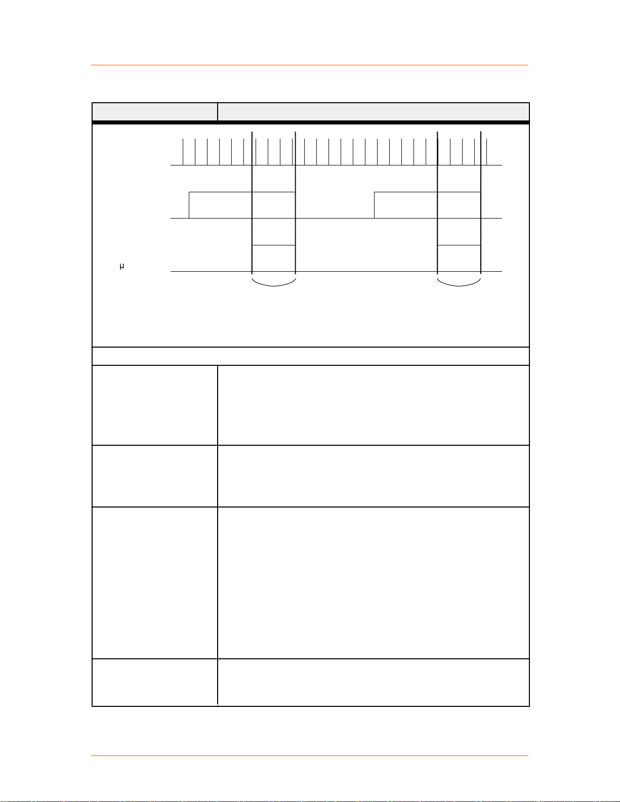
Asynchronous
voltage sample
RF pulse
Sampling window
(150 usec
deadtime)
Valid Sample
Window
Valid Sample
Window
3800
Advanced Energy
®
Table 3‑2. Electrical specifications (Continued)
Description Specification
Figure 3‑1. Timing diagram
Paramount® MF 2 kW Generator
External Voltage Control Mode
General specification When operating the unit in external voltage regulation mode:
• Minimum voltage setpoint in this mode = 0.1 V
• Maximum forward power in the voltage control mode = 1800
W
Control loop response
time
Typical settling time is 8 μs to 10 μs when operating on 50 Ω load
with peak detector from the AE Low Frequency Fixed Match.
Settling time is measured from the start of step disturbance to 90%
change of the output voltage.
Sense Voltage In input
Input specification for this SMA connector:
characteristics
• Input voltage 0 V to 10 V
• Accuracy of voltage measurement ± 0.6% or ± 20 mV
• The input impedance for all analog signals is greater than
10 kΩ
The input has protection from a disconnected cable using a 70 kΩ
pull-up resistor. If the cable is not connected, input voltage is
10.7 V, which causes the generator to pull back output power down
to 0 W.
Bias Voltage Out output
Output specification for this SMA connector:
characteristics
• Output voltage range 0 V to -5 V
57020114-00E Specifications 3‑9
Page 29

Advanced Energy
®
Table 3‑2. Electrical specifications (Continued)
Description Specification
• Accuracy of output voltage ± 0.7% or ± 80 mV (accuracy is
the difference between the digital signal sent to DAC and the
actual output voltage)
• The load impedance should be greater than 1 kΩ
Paramount® MF 2 kW Generator
57020114-00E Specifications 3‑10
Page 30
Advanced Energy
®
COOLING SPECIFICATIONS
CAUTION:
Do not use deionized water for cooling purposes. Deionized water causes
both corrosion and erosion of cooling manifolds.
Table 3‑3. Cooling specifications
Description Specification
Coolant Requirements
Inlet water temperature +5°C to +35°C (+41°F to +95°F)
Flow rate 7.6 lpm (2 gpm), minimum
Paramount® MF 2 kW Generator
Maximum inlet water pressure 6.9 bar (100 psi)
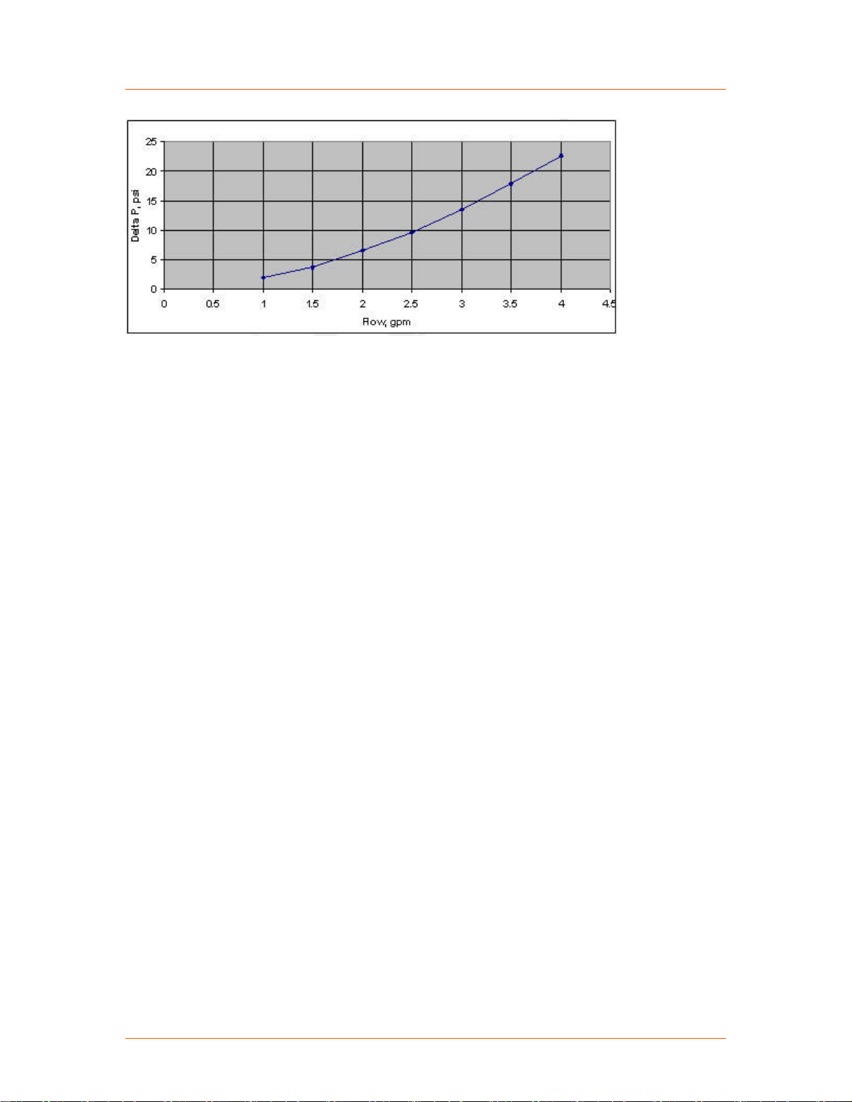
Pressure drop See the following pressure drop figure
Contaminates AE recommends the following specifications for the water
used to cool the Paramount MF 2 kW generator:
• pH between 7.0 and 9.0
• Total chlorine < 20 ppm
• Total nitrate < 10 ppm
• Total sulfate < 100 ppm
• Total dissolved solids < 250 ppm
• Total hardness expressed as calcium carbonate equivalent
less than 250 ppm
• Specific resistivity of 2500 Ω/cm or higher at 25°C
• Total dissolved solids (TDS) as estimated by the
following:
◦ TDS ≤ 640,000 ÷ specific resistivity (Ω/cm)
57020114-00E Specifications 3‑11
Page 31
Advanced Energy
®
Figure 3‑2. Pressure drop
Paramount® MF 2 kW Generator
57020114-00E Specifications 3‑12
Page 32
Advanced Energy
®
Paramount® MF 2 kW Generator
ENVIRONMENTAL SPECIFICATIONS
Table 3‑4. Environmental standard
specifications
Description Specification
Overvoltage Category II
Pollution degree 2
Table 3‑5. Climatic specifications
Temperature Relative Humidity Air Pressure
Operating +5°C to +40°C
+41°F to +104°F
5% to 85%
1 g/m3 to 25 g/m
[1]
78.8 kPa to 106 kPa
3
788 mbar to 1060 mbar
Equivalent altitude: +2000 m
to ‑500 m (+6562′ to ‑1640′)
Storage -25°C to +55°C
-13°F to +131°F
5% to 95%
1 g/m3 to 29 g/m
78.8 kPa to 106 kPa
3
788 mbar to 1060 mbar
Equivalent altitude: +2000 m
to ‑500 m (+6562′ to ‑1640′)
Transportation -25°C to +70°C
-13°F to +158°F
[2]
95%
60 g/m3
[3]
65.6 kPa to 106 kPa
656 mbar to 1060 mbar
Equivalent altitude: +3500 m
to ‑500 m (+11483′ to
‑1640′)
1
Non-condensing, no formation of ice
2
Maximum relative humidity when the unit temperature slowly increases, or when the unit temperature
directly increases from -25°C to +30°C (-13°F to +86°F)
3
Maximum absolute humidity when the unit temperature directly decreases from +70°C to +15°C
(+158°F to +59°F)
57020114-00E Specifications 3‑13
Page 33

Pin 1 Pin 13
Pin 14
Pin 25
Paramount
®
MF 2 kW Generator
Chapter
Communication Controls
25-PIN USER PORT
25-Pin User Port Connector
The User port uses a 25-pin, shielded, female, subminiature-D connector. Ground/
return lines are floating and need to be connected as close to the system as possible.
4
Figure 4‑1. User port connector, 25-pin
User Port Cabling Requirements
The cable used to connect the generator’s User port to the system controller must be
a shielded, 25-wire I/O cable. Twisted-pair wiring may be used but is not mandatory.
Signal losses should be minimized by keeping the cable length as short as possible.
The maximum recommended cable length between the generator and the controller is
10 meters (33′). To minimize interference from adjacent electrical equipment, the
EMI shield in the cable must be terminated to the metal shells of the cable’s
connectors. Additionally, the chassis of the generator must be tied to a local earth
ground through an adequately sized copper grounding strap.
Satisfying Minimal Requirements for the 25-Pin User Port
Regardless of whether you are controlling and monitoring the generator through the
User port or through another port, two User port signals must be satisfied for the unit
to be operational: RF PWR ON (pin 4) and INTERLOCK LOOP (pins 10 and 23). In
other words, even if you are controlling the generator through the serial port
interface, the RF signal must be enabled on the User port, and the interlock satisfied.
57020114-00E Communication Controls 4‑1
☞ Important
If you are controlling your generator through a port other than the User port,
make sure that the control mode is set appropriately (to host mode to control
through the Host port, for example). The control mode can be set through an
AE Host command.
Page 34
Advanced Energy
If you are not using the User port to control or monitor the unit, you can use a
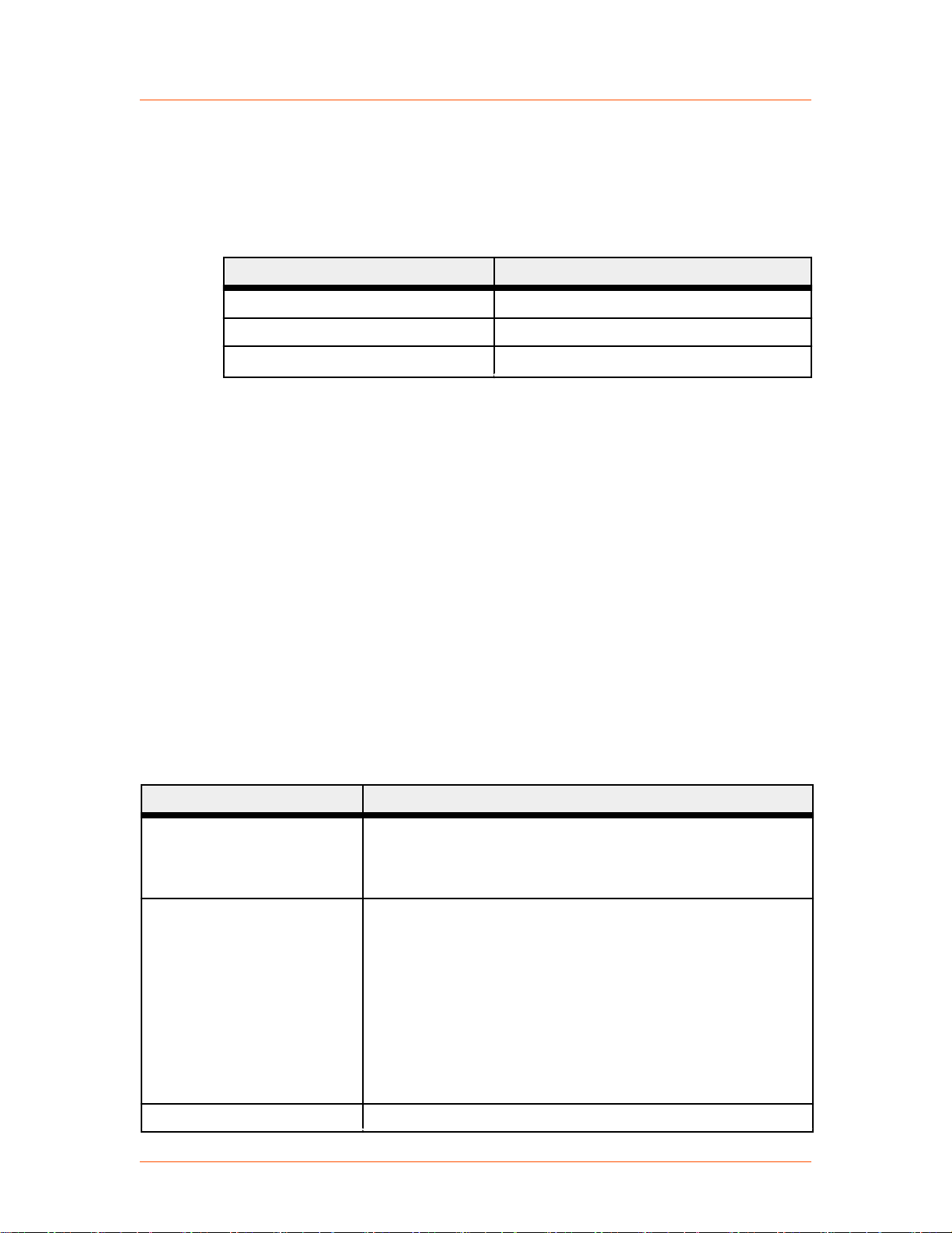
“dummy” or “cheater” plug to satisfy these signals, thereby ignoring the User port.
To make a dummy plug, solder these jumpers on a mating connector.
®
Paramount® MF 2 kW Generator
Table 4‑1. Jumpers on a dummy plug to satisfy minimal signal requirements
Jumper Between Pins Description
4 and 13 Connects RF PWR ON pin to +15 V pin
17 and 21 Satisfies RF PWR ON return to ground
10 and 23 Satisfies INTERLOCK LOOP signal
If desired, you can add an emergency off switch in series with the RF PWR ON signal
(pin 4) and/or tie your system interlocks in series with the generator INTERLOCK
LOOP signal (pins 10 and 23).
If the minimum requirements are met and then AC power is applied, RF output will
not automatically be activated. Choose a control mode, and then, to activate RF
output:
• If you are in host control mode, send an RF on command.
• If you are in user control mode, send an RF off signal and then an RF on signal.
25-Pin User Port Signal and Pin Descriptions
The following tables describe the 25-pin User port signals and pin descriptions.
Wiring diagrams are also provided.
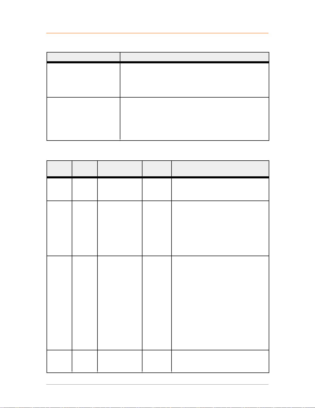
Table 4‑2. User port signal descriptions
Description Specification
Digital inputs (DI) Optocouple-insulated
Logic high: 4 V to 25 V, typical input current 11 mA
Logic low: Less than 1 V
Digital outputs (DO) Optocouplers open or close state
Open (high impedance): V maximum = 30 V (IC < 500 μA)
Close (low impedance): I maximum = 11 mA; Voltage drop is
less than:
• 1.2 V at 0.1 mA
• 3.2 V at 5 mA
• 5.6 V at 11 mA
Analog inputs (AI) Voltage range 0 V to 10 V
57020114-00E Communication Controls 4‑2
Page 35
Advanced Energy
®
Table 4‑2. User port signal descriptions (Continued)
Description Specification
Return wire should be connected to system ground.
Accuracy of voltage measurement: ± 0.6% or ± 20 mV.
The input impedance for all analog input signals is greater than
10 kΩ.
Analog outputs (AO) Voltage range 0 V to 10 V
Return wire should be connected to system ground.
Accuracy of voltage measurement: ± 0.6% or ± 15 mV.
The load impedance for all analog output signals should be
greater than 1 kΩ.
Table 4‑3. 25-pin User port pin descriptions
Signal
Pin
Related
Pin
Name Signal
Type
Paramount® MF 2 kW Generator
Description
1 14 SET POINT
STATUS
RETURN
2 15 RFL PWR
MONITOR
3 16 FWD/LOAD
PWR MONITOR
Digital
output
Analog
output
Analog
output
See pin 14.
This signal provides a linearly scaled
readback of reflected power.
• 0 V = 0 W
• 10 V = 1500 W
See Figure 4‑2 on page 4‑6 for the
wiring diagram.
This signal provides a linearly scaled
readback of forward power when the
generator is operated in forward power
regulation mode or the load power when
operated in load power regulation mode.
In voltage control mode, this signal
provides readback of forward power.
• 0 V = 0 W
• 10 V = Maximum rated output
power
See Figure 4‑3 on page 4‑7 for the
wiring diagram.
4 17 RF PWR ON Digital
input
When logic high is applied to this pin,
RF output is enabled (if generator is in
user control mode). Logic low disables
57020114-00E Communication Controls 4‑3
Page 36

Advanced Energy
®
Table 4‑3. 25-pin User port pin descriptions (Continued)
Signal
Pin
Related
Pin
Name Signal
Type
the RF output. Logic low disables the RF
output in either user control mode or host
control mode.
☞ Important
See Figure 4‑4 on page 4‑7 for the
wiring diagram.
Paramount® MF 2 kW Generator
Description
The interlocks must be satisfied
and the set point must be within
the output power range before
unit will deliver power.
5 18 SET POINT Analog
input
6 19 DC BIAS/
POWER
REGULATION
Digital
input
This pin linearly controls the RF output
of the generator in either forward power
mode or load power mode.
• 0 V to 10 V = 0 W to maximum
rated output power
This input also provides set point in the
voltage control mode.
• 0 V to 10 V = 0 V to 2000 V peak
to peak
See Figure 4‑5 on page 4‑7 for the
wiring diagram.
This pin switches the regulation mode of
the generator.
When logic low is applied to this pin, or
if there is no connection to this pin, the
generator regulates output power (either
forward or load, as defined by the signal
on pin 8).
When logic high is applied to this pin,
the generator regulates in the voltage
control mode.
See Figure 4‑6 on page 4‑8 for the
wiring diagram.
7 Not connected.
8 21 FWD/LOAD
PWR
REGULATION
57020114-00E Communication Controls 4‑4
Digital
input
Applying logic high to this pin causes
the generator to regulate on load power.
Logic low or no connection to this pin
causes the generator to default to
forward power regulation.
Page 37

Advanced Energy
®
Table 4‑3. 25-pin User port pin descriptions (Continued)
Signal
Pin
Related
Pin
Name Signal
Type
In voltage control mode, this pin is
ignored.
See Figure 4‑7 on page 4‑8 for the
wiring diagram.
Paramount® MF 2 kW Generator
Description
9 22 OVERTEMP
RETURN
10 23 INTERLOCK
LOOP
Digital
output
See pin 22.
This pin should connect to pin 23 to
complete the interlock chain. If the
interlock chain is broken, the unit will
not operate. External circuit should be
capable of switching 50 mA at 24 VAC.
Maximum allowed resistance of the
interlock chain is 75 Ω.
See Figure 4‑8 on page 4‑9 for the
wiring diagram.
11 24 DC BUS OK
RETURN
Digital
output
See pin 24.
12 Not connected.
13 21 +15 VDC Analog
output
User voltage for interface purposes.
Rated 400 mA maximum. Short-circuit
protected.
See Figure 4‑9 on page 4‑9 for the
wiring diagram.
14 1 SET POINT
STATUS
Digital
output
When the generator is out of set point by
more than 1% and 3 W, a low (optocoupler output) impedance is created
between this pin and pin 1.
See Figure 4‑10 on page 4‑9 for the
wiring diagram.
15 2 RFL POWER
MONITOR
Analog
output
Signal return for pin 2.
RETURN
16 3 FWD/LOAD
PWR MONITOR
Analog
output
Signal return for pin 3.
RETURN
17 4 RF PWR ON
RETURN
18 5 SET POINT
RETURN
57020114-00E Communication Controls 4‑5
Digital
input
Analog
input
Signal return for pin 4.
Signal return for pin 5.
Page 38
3034
_
+
1000 pF
1000 pF
OP400
2
15
10 Hm
10 Hm
User Unit
Voltage Measurement Device
(see pin description
for scaling)
Pin 15 must
be grounded
Advanced Energy
®
Paramount® MF 2 kW Generator
Table 4‑3. 25-pin User port pin descriptions (Continued)
Signal
Pin
Related
Pin
Name Signal
Type
19 GROUND Signal/chassis ground.
20 Not connected.
21 GROUND Signal/chassis ground.
Description
22 9 OVERTEMP Digital
output
When an internal overtemperature
shutdown condition is detected, a low
(opto-coupler output) impedance is
created between this pin and pin 9.
See Figure 4‑11 on page 4‑10 for the
wiring diagram.
23 10 INTERLOCK
See pin 10.
LOOP RETURN
24 11 DC BUS OK Digital
output
When the interlocks are satisfied and no
faults are present, a low (opto-coupler
output) impedance is created between
this pin and pin 11.
See Figure 4‑12 on page 4‑10 for the
wiring diagram.
25 Not connected.
WIRING DIAGRAMS FOR THE 25-PIN USER PORT
The diagrams in this section provide wiring information to connect to the 25-pin
User port.
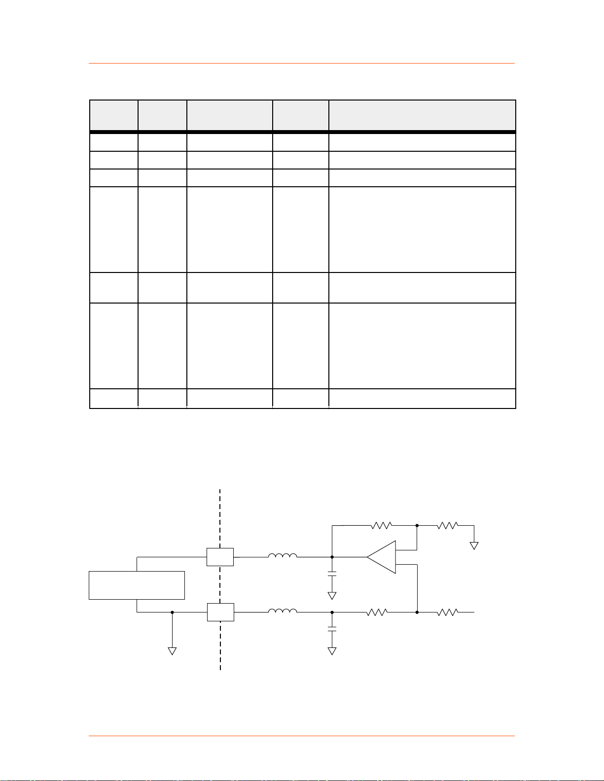
Figure 4‑2. REFL PWR MONITOR (pins 2 and 15)
57020114-00E Communication Controls 4‑6
Page 39
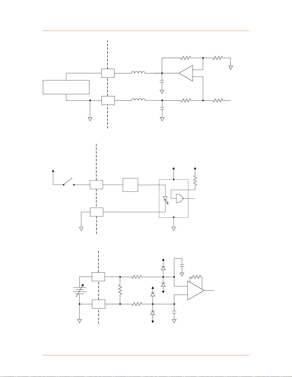
3033
_
+
OP400
10 Hm
10 Hm
3
16
1000 pF
1000 pF
Voltage Measurement Device
(see pin description
for scaling)
Pin 16 must
be grounded
User Unit
3394
4
17
+3.3 V
+3.3 V
User
Unit
+4 V to +25 V
Current
Limiter
11 mA
3035
_
+
-15 V
-15 V
+15 V
+15 V
18
5
100 K
See pin description
for scaling
User
Unit
+
_
Advanced Energy
®
Figure 4‑3. FWD/LOAD PWR MONITOR (pins 3 and 16)
Paramount® MF 2 kW Generator
Figure 4‑4. RF PWR ON (pins 4 and 17)
Figure 4‑5. SET POINT (pins 5 and 18)
57020114-00E Communication Controls 4‑7
Page 40
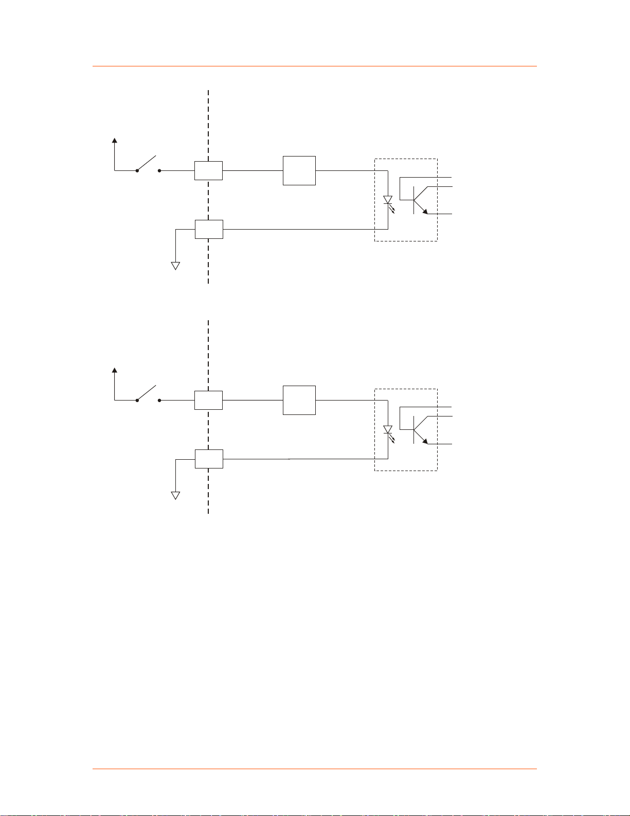
3395
6
19
+4 V to +25 V
User Unit
Current
Limiter
11 mA
3396
8
21
+4 V to +25 V
User Unit
Current
Limiter
11 mA
Advanced Energy
®
Figure 4‑6. DC BIAS/POWER REGULATION (pins 6 and 19)
Paramount® MF 2 kW Generator
Figure 4‑7. FWD/LOAD PWR REGULATION (pins 8 and 21)
57020114-00E Communication Controls 4‑8
Page 41
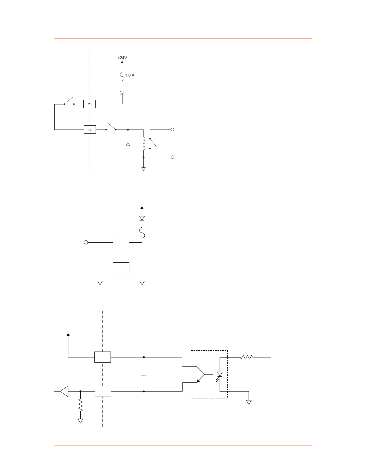
User Unit
Interlock
Interlock return
Cable interlock
Interlock relay
3045
Unit
+15 V
13
21
+15 V provided
to user
3040
14
1
1000 pF
User Unit
+5 V
2 K
TTL or
CMOS
input
Advanced Energy
®
Figure 4‑8. INTERLOCK LOOP (pins 23 and 10)
Paramount® MF 2 kW Generator
Figure 4‑9. +15 VDC (pins 13 and 21)
Figure 4‑10. SET POINT STATUS (pins 14 and 1)
57020114-00E Communication Controls 4‑9
Page 42
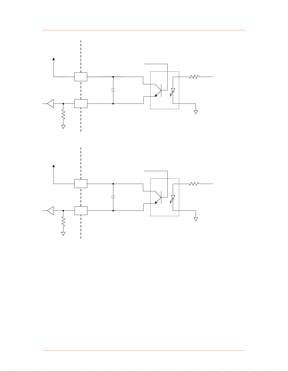
3041
22
9
1000 pF
User Unit
+5 V
2 K
TTL or
CMOS
input
3042
24
11
1000 pF
User Unit
+5 V
2 K
TTL or
CMOS
input
Advanced Energy
®
Figure 4‑11. OVERTEMP (pins 22 and 9)
Paramount® MF 2 kW Generator
Figure 4‑12. DC BUS OK (pins 24 and 11)
AE BUS INTERFACE (HOST PORT)
The Paramount MF 2 kW unit provides a serial communications interface through the
Host port. This interface allows the Paramount MF 2 kW unit to interface with a host
computer using the AE Bus protocol.
To obtain a basic sample of host software for the Host port, please call AE Global
57020114-00E Communication Controls 4‑10
Services.
AE manufactures a more full-function interface software for some products, called
Virtual Front Panel, which allows you to use a host computer to communicate with
Page 43

Pin 1
Advanced Energy
®
the unit through the Host port. To find out more about this software, please call
AE Global Services.
Host Connector
The serial Host port connector is a 9-pin, female, shielded, subminiature-D connector
for interfacing with a host computer.
Figure 4‑13. Host port connector
Host Port Pin Descriptions
Paramount® MF 2 kW Generator
Table 4‑4. Host port pin descriptions
Signal
Name Description
Pin
1 RESERVED Reserved for future use
2 TX RS232 RS-232 transmit data
3 RX RS232 RS-232 receive data
4 RESERVED Reserved for future use
5 COM Data common
6 RESERVED Reserved for future use
7 RESERVED Reserved for future use
8 RESERVED Reserved for future use
[1]
9
1
Do not ground this factory reserved pin. Grounding this pin disrupts the
operation of the unit.
Do not connect pins marked RESERVED.
RESERVED (FACTORY) Reserved for future use
AE Bus Transmission Parameters
The communications capability of the Host port is limited to the following
parameters:
• RS-232 protocol
• Baud rates:
◦ 9600
57020114-00E Communication Controls 4‑11
Page 44

Baud rate
Unit address
Communication mode
Advanced Energy
• Paramount MF 2 kW unit addresses 1 to 31
• Odd parity
• One start bit, eight data bits, one stop bit
• Low-order bytes transmitted before high-order bytes (little endian)
The timeout period for the Paramount MF 2 kW unit is factory set at 0.75 seconds
(that is, no more than 0.75 seconds can elapse between bytes, or the unit will reset
and begin searching for a new message packet). Use command 40 to change this
value.
The host computer must finish one transaction with the Paramount MF 2 kW unit
before it initiates another transaction, either with the same unit or any other unit.
The Paramount MF 2 kW unit sends data through pin 2 (TX RS-232). This pin must
be connected to the receive pin (RX RS-232) on the host computer’s serial connector.
The receive pin is normally pin 2 for a standard, 9-pin serial port.
®
◦ 19200
◦ 57600
◦ 115200
Paramount® MF 2 kW Generator
Host Port DIP Switches
DIP SWITCH AND SWITCH SETTINGS
Use the DIP switch to set the baud rate and the AE Bus address for your unit.
Figure 4‑14. Slide DIP switch
The DIP switch contains eight individual switches. Setting a switch to the on position
means sliding the switch toward the numbers on the DIP, and setting a switch to the
off position means sliding it away from the numbers.
SWITCHES
The first five switches (1 to 5) specify the address of the unit, which a host computer
must include in the message packet it sends.
The next two switches (6 and 7) specify the AE Bus port baud rate.
Switch 8 (communication mode) is unused.
57020114-00E Communication Controls 4‑12
Page 45
Advanced Energy
SETTING THE BAUD RATE
Use the DIP switch to set the serial AE Bus port baud rate.
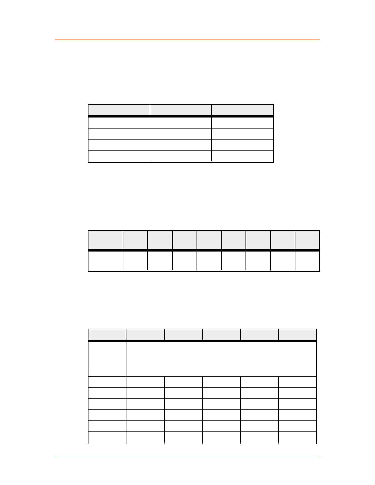
Table 4‑5. DIP switch settings for variable baud rate, switches
6 and 7
DEFAULT DIP SWITCH SETTINGS
The default Host settings for the unit are AE Bus address 1, baud rate 19200, and
RS-232 communication mode.
®
Baud Switch 6 Switch 7
9600 On On
19200 On Off
57600 Off On
115200 Off Off
Paramount® MF 2 kW Generator
Table 4‑6. Default dip switch settings
Switch
number
Default
position
1 2 3 4 5 6 7 8
on on on on off on off on
SETTING THE UNIT AE BUS ADDRESS
Use the DIP switch to set the unit AE Bus address.
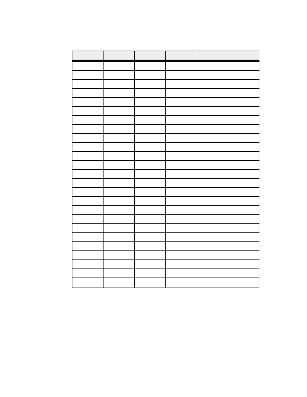
Table 4‑7. AE Bus address settings
Address Switch 1 Switch 2 Switch 3 Switch 4 Switch 5
0 Do not assign this address to a unit; it is the AE Bus broadcast
address. All AE Bus units receive a message sent to this address by
the host, but will not reply. If you set the address to 0, the unit
automatically reassigns the address to 1
1 On On On On Off
2 On On On Off On
3 On On On Off Off
4 On On Off On On
5 On On Off On Off
6 On On Off Off On
57020114-00E Communication Controls 4‑13
Page 46
Advanced Energy
®
Paramount® MF 2 kW Generator
Table 4‑7. AE Bus address settings (Continued)
Address Switch 1 Switch 2 Switch 3 Switch 4 Switch 5
7 On On Off Off Off
8 On Off On On On
9 On Off On On Off
10 On Off On Off On
11 On Off On Off Off
12 On Off Off On On
13 On Off Off On Off
14 On Off Off Off On
15 On Off Off Off Off
16 Off On On On On
17 Off On On On Off
18 Off On On Off On
19 Off On On Off Off
20 Off On Off On On
21 Off On Off On Off
22 Off On Off Off On
23 Off On Off Off Off
24 Off Off On On On
25 Off Off On On Off
26 Off Off On Off On
27 Off Off On Off Off
28 Off Off Off On On
29 Off Off Off On Off
30 Off Off Off Off On
31 Off Off Off Off Off
AE Bus Protocol
The AE Bus protocol uses pure binary data (nothing is coded in ASCII) and is
designed to facilitate direct communications between a host computer and the
Paramount MF 2 kW unit. The AE Bus message packet combines a set quantity of
bits and bytes in such a way that groups of information can be sent over
communications lines at one time. Five types of information (fields) make up a
communications message packet.
• Header (address and the length of data field)
57020114-00E Communication Controls 4‑14
Page 47
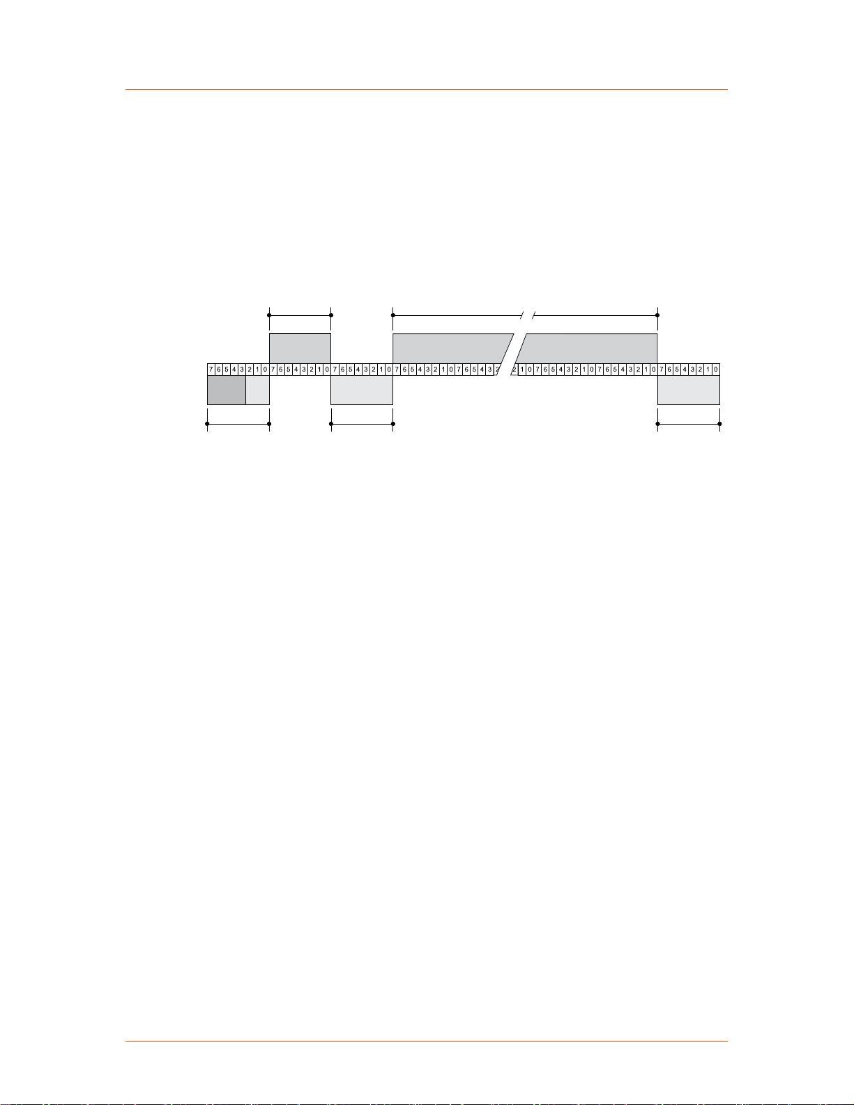
Command number
0-255
Header
5-bit address
3-bit length
Optional length byte
Data (0-255 bytes)
Checksum
Advanced Energy
• Command number
• Optional length byte
• Data
• Checksum
Figure 4‑15 shows the organization of these fields in the AE Bus message packet.
The subsequent paragraphs describe each field in detail.
®
Paramount® MF 2 kW Generator
Figure 4‑15. Graphic representation of a message packet
AE BUS HEADER BYTE
The first byte in each packet contains two pieces of information: five bits contain the
packet address, and three bits contain the data byte count. If the message packet
originates with the host computer, the address specifies the packet destination (to the
Paramount MF 2 kW unit, for example). If the packet is going to the host, the address
specifies the packet origin (from the Paramount MF 2 kW unit). The address section
of the header field is five bits long (bits 3 to 7), which allows a total of 32 distinct
addresses. Address 0 (zero) is reserved for the network broadcast address, which the
Paramount MF 2 kW unit does not support.
The remaining three bits (bits 0, 1, and 2) are the length bits. These bits tell the
receiving unit how long the data field is so that the unit can determine when it has
received the entire message. If the data field contains more than six bytes, the value
of these three bits will be set to 7 (07h), and the optional length byte field will
contain a value indicating the number of data bytes in the data field.
☞ Important
The value of these bits refers only to the number of actual data bytes in the
data field. Do not include the checksum byte when calculating the value for
these bits.
57020114-00E Communication Controls 4‑15
AE BUS COMMAND NUMBER BYTE
This 1-byte field contains an 8-bit value from 0 to 255 (00h to ffh) representing the
command number. If the message packet originates with the host computer, this value
Page 48

Advanced Energy
specifies the purpose of the message packet. If the message originates with the
Paramount MF 2 kW unit, the value specifies the command to which it is responding.
AE BUS OPTIONAL LENGTH BYTE
This field supplements the header field and exists only when the length bits (bits 0, 1,
and 2) in the header field contain a value of 7 (07h). If the number of data bytes in
the data field is ≤ 6, then the three length bits in the header field are sufficient to
represent this amount, 0 to 6 (00h to 06h). Since the data field contains up to 255
bytes of information, the optional length byte is required when the data field is larger
than six bytes.
When the data field is larger than six bytes, the length bits in the header (bits 0, 1,
and 2) equals 7 (07h) and the optional length byte contains a 1-byte value, from 7 to
255 (07h to ffh), representing the number of data bytes in the data field.
AE BUS DATA BYTES
The data field contains 0 to 255 bytes of binary data. This field contains commandrelated data or a command status response (CSR). Since some commands do not
require data, sometimes the data field is not present.
®
Paramount® MF 2 kW Generator
If the value specified in the length bits (bits 0, 1, and 2) of the header field is 0 to 6,
the Paramount MF 2 kW unit expects 0 to 6 data bytes. However, if the value in the
header field is 7 (07h), the Paramount MF 2 kW unit looks for the optional length
byte after the command field and reads this value to calculate the data byte count.
Unless otherwise specified for individual commands, AE Bus protocol is little
endian, which means that all values greater than 1 byte are sent in little endian order.
For example, a command with 7 data bytes that included one 8-bit value, one 16-bit
value, and one 32-bit value, would be sent as shown in Table 4‑8.
Table 4‑8. AE Bus byte structure
Value to Send Byte Configuration
8-bit value = 15 Byte 1 = 0x0F
16-bit value = 23450 Bytes 2 and 3 = 0x9A 0x5B
32-bit value = 147679 Bytes 4 to 7 = 0xDF 0x40 0x02 0x00
AE BUS CHECKSUM BYTE
This 1-byte field is the last byte in the packet. The value of this byte depends upon
the number of bytes in each of the preceding fields. The transmitting unit determines
this value by accumulating the exclusive-or (XOR) of all bytes of the packet up to,
but not including, the checksum value. The receiving unit accumulates the XOR of
all bytes of the packet, including the checksum. If the result is zero, the unit has
received the packet intact.
57020114-00E Communication Controls 4‑16
Page 49
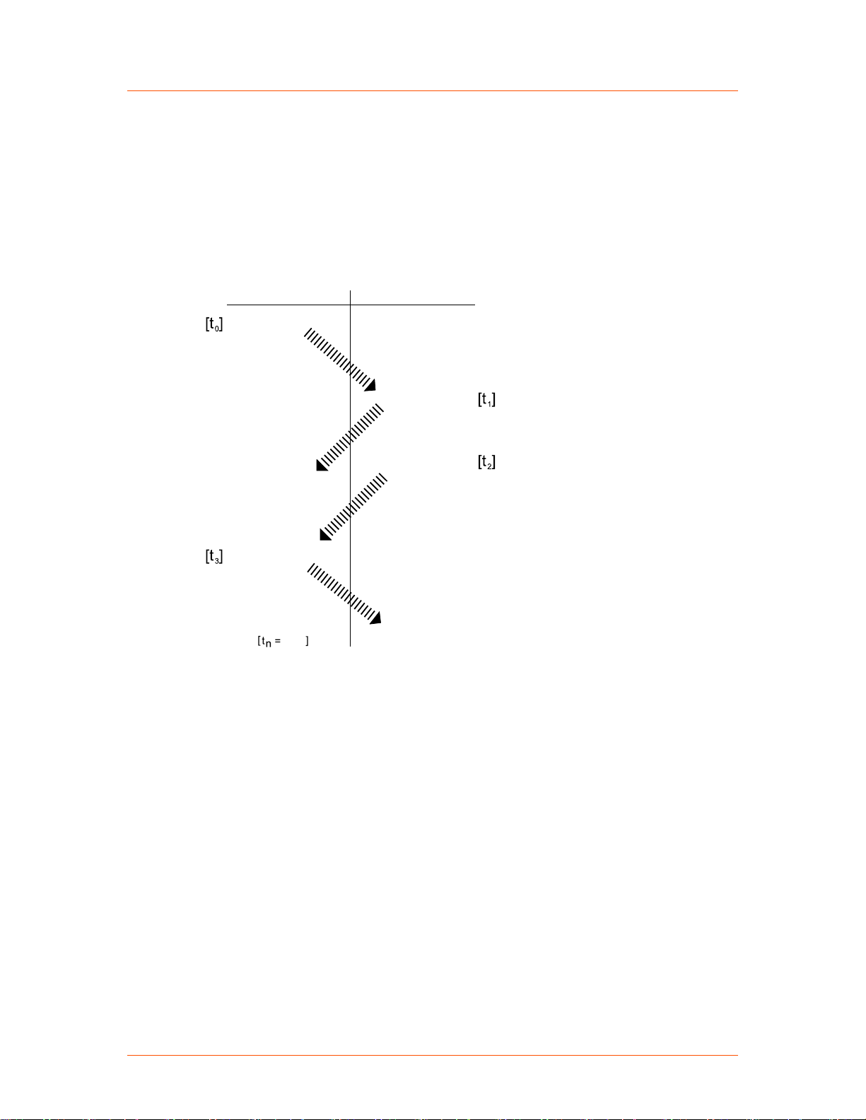
Waits
Receives packet
Sends ACK
Receives ACK
time
Receives packet
Transmits
message
packet
Assembles
CSR byte
or
data byte(s),
then transmits
END OF TRANSACTION
Waits
Waits
Receives ACK
Sends ACK
Host computer Unit
Advanced Energy
®
Paramount® MF 2 kW Generator
The unit will act on the message only if the address is valid and the checksum is
validated.
Creating an Ideal Communications Transaction
Figure 4‑16 illustrates the steps in an ideal communications transaction between a
host computer and the Paramount MF 2 kW unit.
Figure 4‑16. AE Bus communications transaction
T0: HOST TRANSMITS MESSAGE PACKET
The host computer sends a message packet to the Paramount MF 2 kW unit. The
57020114-00E Communication Controls 4‑17
packet contains one of the following:
T1: UNIT VERIFIES HOST TRANSMISSION PACKET
Once the Paramount MF 2 kW unit receives the host computer transmission message
packet, the Paramount MF 2 kW unit verifies that the message is intended for it and
not for another unit on the network. At this time, the Paramount MF 2 kW unit also
analyzes the checksum to verify that the message was received correctly.
• A command that requests data or status information
• A command and data that change a parameter setting
• An executable command
• If the address does not match, the Paramount MF 2 kW unit does not respond to
the host computer; the Paramount MF 2 kW unit resets and resumes waiting for
Page 50

Advanced Energy
• If the address matches and the message is intact, the Paramount MF 2 kW unit
If the Paramount MF 2 kW unit receives a request for data or status information, it
gathers and sends the requested information. Otherwise, it evaluates the incoming
command and sends a message packet that contains a 1-byte data value (CSR code)
to the host. The power supply sends CSR code 0 when it has accepted the command.
If the host computer receives a NAK from the Paramount MF 2 kW unit, the host
computer either retransmits the packet or does whatever else it has been programmed
to do in this situation. If the host computer receives an ACK, it waits for the
requested data or status information, or it waits for the CSR code telling it whether or
not the new parameter was accepted. If the host computer receives no response
within a reasonable period, it takes whatever action it has been programmed to take.
®
Paramount® MF 2 kW Generator
a message addressed to it. If the address matches but the exclusive-or (XOR)
sum of the bytes in the packet (including the checksum) is not zero, the
Paramount MF 2 kW unit sends a negative acknowledgment (NAK),
hexadecimal 15h, to the host computer.
sends an acknowledgment (ACK), hexadecimal 06h, to the host computer.
T2: UNIT TRANSMITS RESPONSE TO HOST
The Paramount MF 2 kW unit prepares a response packet with the requested
information or appropriate CSR code, which it then transmits to the host computer.
The host computer then determines, by means of the checksum, if the response
packet is complete. If the host computer detects an error in the transmission (the
checksum is not validated), it can request the packet be sent again by transmitting a
NAK.
T3: HOST ACKNOWLEDGES UNIT RESPONSE
If the Paramount MF 2 kW unit receives an ACK from the host computer, it returns
to the normal waiting state. If the Paramount MF 2 kW unit receives a NAK from the
host computer, the unit retransmits the response packet. The Paramount MF 2 kW
unit continues to retransmit in response to NAK transmissions until the host
computer stops the cycle. If the Paramount MF 2 kW unit receives no response, it
assumes an ACK and returns to the waiting state.
AE BUS COMMUNICATIONS TRANSACTION EXAMPLE
Figure 4‑17 illustrates the steps in an example communications transaction between a
host computer and the Paramount MF 2 kW unit.
57020114-00E Communication Controls 4‑18
Page 51
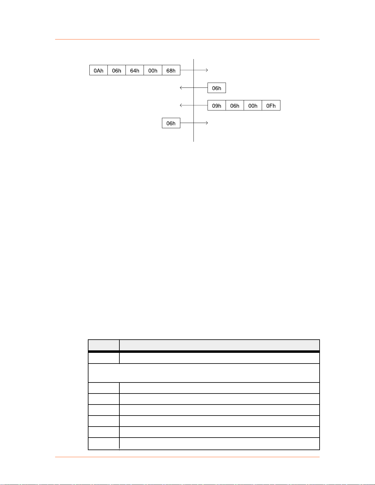
Cmd Data
ACK
Cmd
CSR
Header
Host computer Unit
Chksum
ChksumHeader
ACK
Time
Advanced Energy
®
Figure 4‑17. Communications transaction example
AE HOST COMMANDS
Paramount® MF 2 kW Generator
The following sections describe the command status response (CSR) codes returned
by the Paramount MF 2 kW unit in response to a command, as well as the AE Host
commands for the Paramount MF 2 kW unit.
AE Host Command Status Response (CSR) Codes
When the Paramount MF 2 kW unit receives a command requesting a change in unit
operation (commands 1 through 127), or when the Paramount MF 2 kW unit receives
any command that it rejects (commands 1 through 255), it responds with a command
status response (CSR) code. The CSR is a single-byte number that indicates whether
the unit accepted or rejected the command and, in the case of rejection, the reason the
unit could not respond to the command.
Table 4‑9. AE Host command status response (CSR) codes
Code Meaning
The following CSR codes are sent in response to a command that was not accepted
and provide an indication of why the command was not accepted
0 Command accepted
1 Control mode is incorrect
2 Output is on (change not allowed)
57020114-00E Communication Controls 4‑19
4 Command specifies a value that exceeds the limit for that parameter
5 User port off signal is active.
7 One or more faults are active.
8 Set point ramping is active.
Page 52
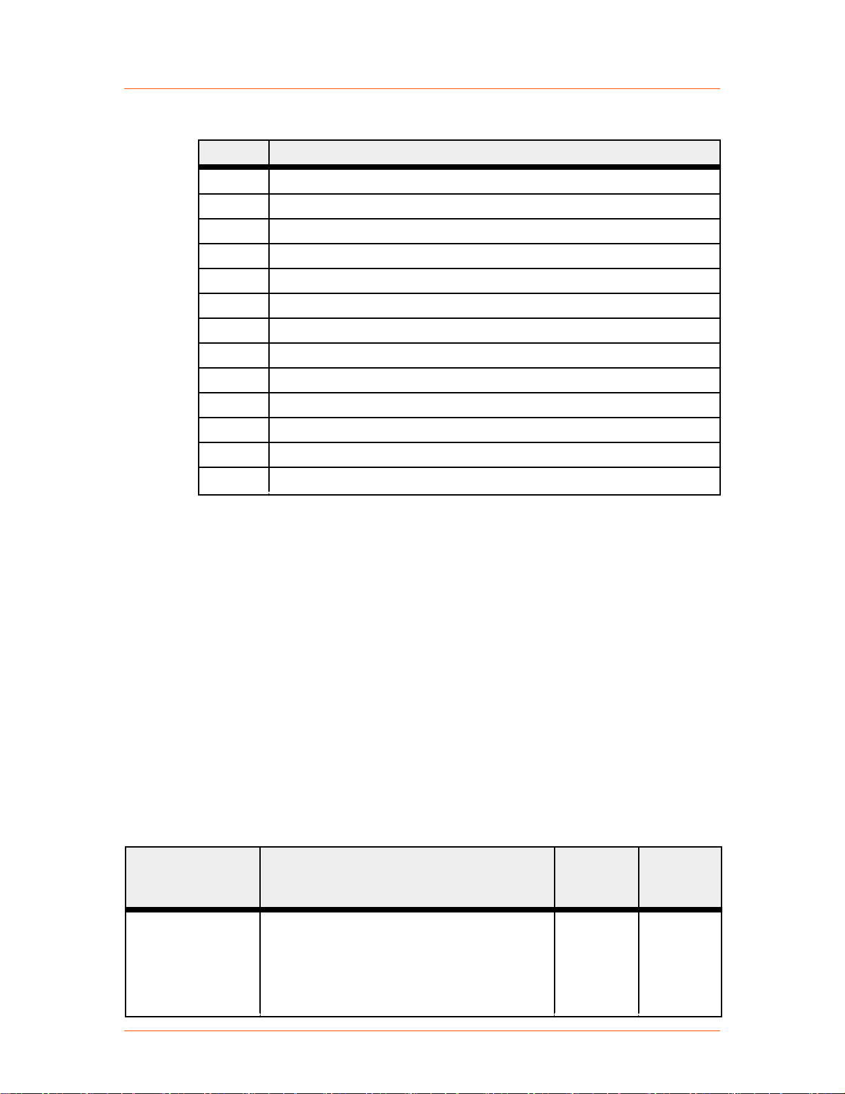
Advanced Energy
®
Paramount® MF 2 kW Generator
Table 4‑9. AE Host command status response (CSR) codes (Continued)
Code Meaning
9 Command’s data byte count is incorrect.
12 Feature is not available on this unit.
17 Minimum off time is active.
28 Set point exceeds user limit.
30 EEPROM read/write error.
41 One or more warnings are active.
42 DHCP is active.
50 Frequency is out of range.
51 Duty cycle is out of range.
52 Minimum on or off time is violated.
61 Real time clock was busy.
63 Flash mode is active.
99 Command not accepted (there is no such command).
AE Host Command Set
• Commands 1 through 127 request a change to the Paramount MF 2 kW unit,
such as changing a setting in the unit. The unit responds to these commands by
sending a command status response (CSR). This single-byte response indicates
whether the unit has accepted or rejected the command and, in the case of
rejection, the reason the unit could not respond to the command.
• Commands 128 through 255 request information from the unit, such as unit
settings. The unit responds to these commands by sending the data requested if
the command was successful, and a CSR if the command was not successful.
Unless otherwise specified for individual commands, AE Bus protocol is little
endian, which means that all values greater than 1 byte are sent least significant byte
first.
Table 4‑10. AE Host commands
Command Description Data Bytes
1
RF Off
Turns RF output off. Accepted regardless of
control mode. This command explicitly clears
all latched faults, but it does not clear any
faults that are currently active.
Command 162 reports this value.
Sent
Returned
0 1
Data
Bytes
57020114-00E Communication Controls 4‑20
Page 53

Advanced Energy
®
Paramount® MF 2 kW Generator
Table 4‑10. AE Host commands (Continued)
Command Description Data Bytes
Sent
Data
Bytes
Returned
2
RF On
3
set regulation mode
4
set user power limit
Turns RF output on if there are no active or
latched faults or warnings. Accepted only
when host control mode is active.
Command 162 reports this value.
Sets the regulation mode.
Send 1 data byte (8-bit value):
• 6 = Forward
• 7 = Delivered or load
• 8 = External (DC bias)
Command 154 reports this value.
Sets the user power limit. You cannot change
the power limit while the unit is on. Valid
values are from the low power limit to the
unit maximum power.
The user power limit is directly related to the
active regulation mode. For example, when in
load regulation mode, the user power limit
will limit delivered power.
Send 2 data bytes (16-bit value) = Power limit
in watts
Command 169 reports this value.
0 1
1 1
2 1
5
set user reflected
power limit
Sets the user reflected power limit in watts.
The user reflected power limit affects all
regulation modes. The unit retains the user
2 1
reflected power limit as long as power is
applied. If power is cycled, the reflected
power limit returns to the default value, the
specified reflected power maximum.
You cannot change the user reflected power
limit while the output is on. Valid values are
from the specified reflected power minimum
to the specified reflected power maximum.
Send 2 data bytes (16-bit value) = Reflected
power limit in watts
Command 170 reports this value.
6
set user external
feedback limit
57020114-00E Communication Controls 4‑21
Sets the user external feedback limit in volts.
The user external feedback limit affects only
the external DC bias regulation mode. The
2 1
Page 54

Advanced Energy
®
Paramount® MF 2 kW Generator
Table 4‑10. AE Host commands (Continued)
Command Description Data Bytes
unit retains the user external feedback limit as
long as power is applied. If power is cycled,
the external feedback limit returns to the
default value, 2000 V.
You cannot change the user external feedback
limit while the output is on. Valid values are
from 1% of the maximum external feedback
value minimum up to the maximum external
feedback value (set with command 9).
Send 2 data bytes (16-bit value) = External
feedback limit in volts
Command 171 reports this value.
Sent
Data
Bytes
Returned
7
restore factory
defaults
8
set power setpoint
Restores all nonvolatile RAM values to the
factory preset values. See individual product
specifications for factory default parameters.
For more information, contact AE Global
Services.
Send 2 data bytes (16-bit value):
• 0 = Restore all default values
Sets a power setpoint in watts. Sets a setpoint
in volts when operating in external (DC bias)
regulation mode. Setpoint cannot be greater
than the unit's maximum output power or the
user power limit. Setpoint cannot be greater
than the maximum external feedback value
when in external regulation mode.
• User power limit = Set with command 4
Accepted only when host control mode is
active.
Send 2 data bytes (16-bit value) = Power
setpoint in watts.When operating in external
(DC bias) regulation mode, the setpoint is in
volts.
Command 164 reports this value.
2 1
2 1
9
set maximum
external feedback
value (NV)
Sets the maximum external feedback value in
volts. This setting only affects the unit in the
external (DC bias) regulation mode. The unit
stores the maximum external feedback value
3 1
in nonvolatile memory. You cannot change the
57020114-00E Communication Controls 4‑22
Page 55
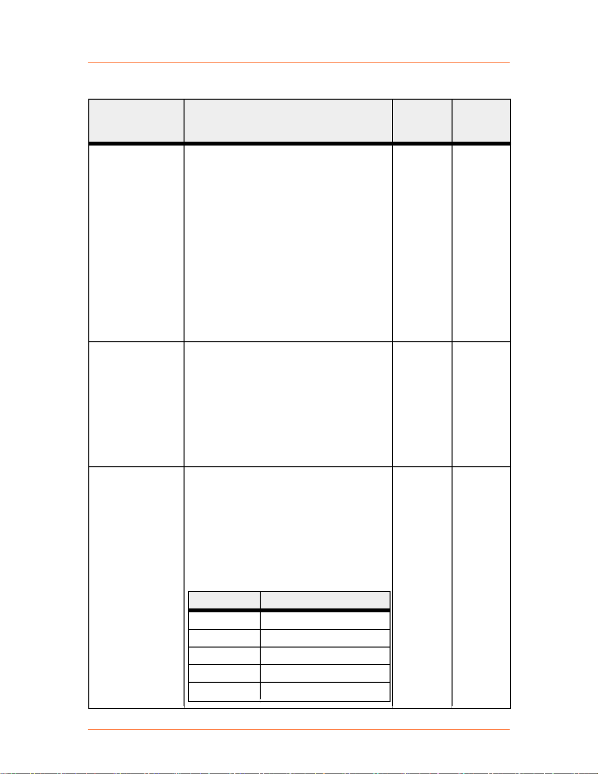
Advanced Energy
®
Paramount® MF 2 kW Generator
Table 4‑10. AE Host commands (Continued)
Command Description Data Bytes
maximum external feedback value while the
output is on.
Valid values are from 10 V to 65535 V. If the
new maximum external feedback value is less
than the user external feedback limit, the unit
reduces the user external feedback limit to
equal to the new maximum external feedback
value.
Send 3 data bytes:
• Bytes 0 and 1 = Maximum external
feedback value in volts
• Byte 2 = Dummy byte for RFX II
compatibility (can contain any value)
Sent
Data
Bytes
Returned
14
set active control
mode
26
set pulsing
configuration
Sets the control mode. This mode cannot be
changed while the output is on.
Send 1 data byte (8-bit value):
• 2 = Host
• 4 = User port (analog)
• 8 = Diagnostic
Command 155 reports this value.
Set pulsing configuration. Set unit as master
or slave, turn pulse sync input on or off, set
memory mode, set explicit enable mode, and
enable or disable pulsing mode.
This command allows you to send
subcommands. Send a value in the first two
bytes that selects the parameter to set, and
then send subcommands to set parameter
values.
Byte 0-1 = Subcommand
1 Set pulsing mode
1 1
6 1
2 Set pulse sync output
3 Reserved
4 Reserved
5 Set memory mode
57020114-00E Communication Controls 4‑23
Page 56
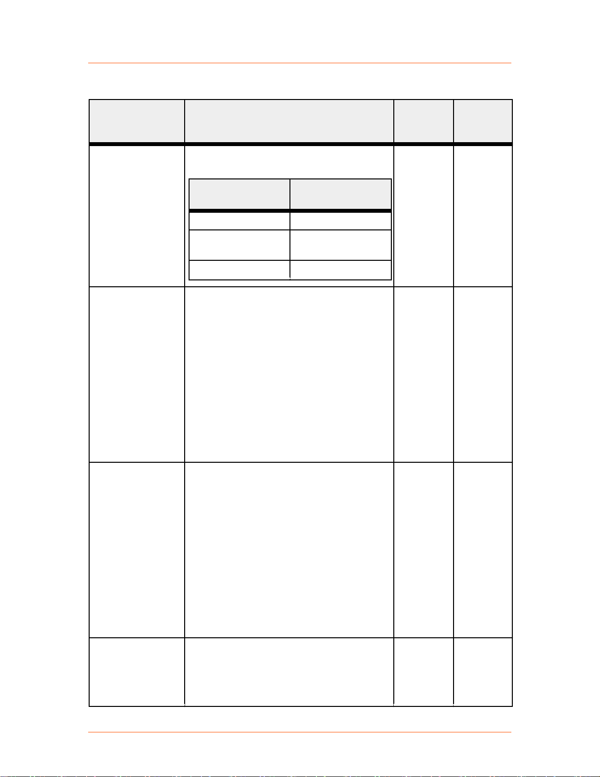
Advanced Energy
®
Paramount® MF 2 kW Generator
Table 4‑10. AE Host commands (Continued)
Command Description Data Bytes
The following table shows the factory set/
default values for pulsing parameters.
Parameter Factory Set/
Default Value
Pulsing mode Master mode
Sent
Data
Bytes
Returned
26
set pulsing mode
(subcommand 1)
26
enable pulse sync
output
(subcommand 2)
Enable pulse sync
output
Pulse sync output
enabled
Memory mode RAM
Sets the unit pulsing mode to master or slave.
You can not use this command while RF
output is on.
Send 6 data bytes.
• Bytes 0 and 1 = 1 (set pulsing mode)
• Bytes 2 and 3 = Pulsing mode
◦ 1 = Master mode
◦ 2 = Slave mode
• Bytes 4 and 5 = Reserved
Command 172 B0 = 1 reports these values.
Enables or disables pulse sync output.
Send 6 data bytes.
• Bytes 0 and 1 = 2 (enable/disable pulse
sync output)
6 1
6 1
• Bytes 2 and 3 = Pulse sync output on or
off
◦ 0= Pulse sync output off
◦ 1= Pulse sync output on
• Bytes 4 and 5 = Reserved
Command 172 B0 = 2 reports these values.
26
set memory mode
Sets the unit memory mode to RAM or
NVRAM. The unit saves parameters to the
6 1
currently active memory as specified by this
(subcommand 5)
value. Future parameter changes will also be
saved to the current active memory.
57020114-00E Communication Controls 4‑24
Page 57

Advanced Energy
®
Paramount® MF 2 kW Generator
Table 4‑10. AE Host commands (Continued)
Command Description Data Bytes
Send 6 data bytes.
• Bytes 0 and 1 = 5 (set memory mode)
• Bytes 2 and 3 = Memory mode
◦ 0 = RAM
◦ 1 = NVRAM
• Bytes 4 and 5 = Reserved
Command 172 B0 = 5 reports these values.
Sent
Data
Bytes
Returned
31
set setpoint ramping
configuration
Sets the setpoint ramping mode and ramp
parameters or sets ramping memory mode.
The ramp up and down parameters can be set
independently.
Send 6 or 8 data bytes. Sending 6 data bytes
allows you to set the setpoint ramping mode
and ramp parameters. Sending 8 data bytes
allows you to select a subcommand, and then
set the setpoint ramping mode and parameters
or set the ramping memory mode.
Ramping Mode and Parameters
In W/s mode, the ramp parameters represent
the ramp rate in watts per second. The
acceptable range for the ramp up and ramp
down parameters in W/s mode is 1 W/s to
65535 W/s.
In timed mode, the ramp parameters represent
the time in ms. The acceptable range for the
ramp up and ramp down parameters in timed
mode is 1 ms to 65535 ms.
The setpoint ramp parameters can be set while
output is on. The ramp parameters are not
allowed to change during a setpoint ramp that
is currently in progress. The setpoint will not
be ramped in either mode if the setpoint
change is less than 1 W.
6 or 8 1
6 Data Byte Version
Send 6 data bytes (three 16-bit values):
• Bytes 0 and 1 = Ramp mode
57020114-00E Communication Controls 4‑25
Page 58

Advanced Energy
®
Paramount® MF 2 kW Generator
Table 4‑10. AE Host commands (Continued)
Command Description Data Bytes
◦ 0 = Disabled
◦ 1 = Watts/second (W/s)
◦ 2 = Timed (in ms)
• Bytes 2 and 3 (16-bit value) = Ramp up
(in W/s or time in ms)
• Bytes 4 and 5 (16-bit value) = Ramp
down (in W/s or time in ms)
8 Data Byte Version
Send 8 data bytes to set either ramp data or
memory mode.
To set ramp data:
Sent
Data
Bytes
Returned
38
set tuning time‑out
value
• Bytes 0 and 1 = 1 (set ramp data)
• Bytes 2 and 3 = Ramp mode (0 =
Disabled, 1 = W/s, 2 = ms)
• Bytes 4 and 5 = Ramp up (in W/s or time
in ms)
• Bytes 6 and 7 = Ramp down (in W/s or
time in ms)
To set the memory mode:
• Bytes 0 and 1 = 2 (set memory mode)
• Byte 2 and 3 = Memory mode (0 =
RAM, 1 = NVRAM)
• Bytes 4 through 7 = 0
Command 151 reports this value.
Sets the time in ms that the generator is
allowed to tune without finding a match
before it turns off RF output and activates a
fault. The unit stores this setting in nonvolatile
memory. You cannot change this mode while
output is on. A value of 0 disables tuning
time-out, causing the generator to tune
indefinitely.
Command 138 reports this value.
4 1
57020114-00E Communication Controls 4‑26
Page 59

Advanced Energy
®
Paramount® MF 2 kW Generator
Table 4‑10. AE Host commands (Continued)
Command Description Data Bytes
Sent
Data
Bytes
Returned
39
set communications
watchdog timer
Sets the communications watchdog timer
value in ms. This timer denotes the amount of
time that can pass without a successful
communication. If this timer value is
exceeded, the unit will turn output off if the
output is on.
Each AE Bus communications interface has
its own unique watchdog timer. To set the
watchdog timer value for a given port (for
example, the Host port), send this command
from that port. You can set up any
combination of enable, disable, or time-out
values among the interfaces. A value of 0
disables the watchdog timer.
This parameter is volatile and defaults to 0 ms
each time you turn the unit on. The maximum
value is 65535 ms. The unit stores the
watchdog timer value internally in 10 ms
increments, and truncates any fractional
remainder. The unit accepts a value from 1 to
9, but stores it as a time‑out period of 10 ms.
Send 3 data bytes:
3 1
40
set host port time-
out
• Byte 0 = Enable/disable timer
• Bytes 1 and 2 = Timer value in ms. Valid
values are 1 to 65535 ms
Command 139 reports this value
Sets the amount of time that the generator
waits between bytes from the host before
resetting and waiting for a new packet. Each
AE Bus communications interface has its
own unique host port time-out. To set the host
port time-out value for a given port (for
example, the Host port), send this command
from that port.
Send 2 data bytes (16-bit value) representing
units of 10 ms for the time-out value. The
valid range of values is from 2 to 500 (20 ms
to 5.0 s). The default value is 750 ms.
Command 140 reports this value.
2 1
57020114-00E Communication Controls 4‑27
Page 60

Advanced Energy
®
Paramount® MF 2 kW Generator
Table 4‑10. AE Host commands (Continued)
Command Description Data Bytes
Sent
Data
Bytes
Returned
44
set minimum tuning
frequency
45
set maximum tuning
frequency
Sets the minimum frequency that the
generator uses for automatic tuning. The unit
stores this parameter in nonvolatile memory.
You cannot change this setting while output is
on.
Send 4 data bytes to set the value in kHz, or 5
data bytes to set the value in either kHz or Hz.
Send 4 data bytes:
• Frequency in kHz
Send 5 data bytes:
• Byte 0 = kHz or Hz
◦ 0 = Frequency is in kHz
◦ 1 = Frequency is in Hz
• Bytes 1 through 4 = Frequency value
Command 144 reports this value.
Sets the maximum frequency that the
generator uses for automatic tuning. The unit
stores this parameter in nonvolatile memory.
You cannot change this setting while output is
on.
Send 4 data bytes to set the value in kHz, or 5
data bytes to set the value in either kHz or Hz.
Send 4 data bytes:
4 or 5 1
4 1
• Frequency in kHz
Send 5 data bytes:
• Byte 0 = kHz or Hz
◦ 0 = Frequency is in kHz
◦ 1 = Frequency is in Hz
• Bytes 1 through 4 = Frequency value
Command 145 reports this value
46
set tuning start
frequency
Sets the frequency at which the generator
starts automatic tuning. The unit stores this
parameter in nonvolatile memory. You cannot
4 or 5 1
change this setting while output is on.
57020114-00E Communication Controls 4‑28
Page 61

Advanced Energy
®
Paramount® MF 2 kW Generator
Table 4‑10. AE Host commands (Continued)
Command Description Data Bytes
Send 4 data bytes to set the value in kHz, or 5
data bytes to set the value in either kHz or Hz.
Send 4 data bytes:
• Frequency in kHz
Send 5 data bytes:
• Byte 0 = kHz or Hz
◦ 0 = Frequency is in kHz
◦ 1 = Frequency is in Hz
• Bytes 1 through 4 = Frequency value
Command 146 reports this value.
Sent
Data
Bytes
Returned
48
set fixed or sweep
frequency mode
58
set retuning
threshold
Sets the frequency control mode. You can
change this mode while the output is on.
While the output is on, changing to fixed
frequency mode causes the unit to change
immediately to the previously set fixed
frequency. Changing to sweep frequency
mode causes the unit to output the start
frequency first, and then to begin sweeping
according to the tuning algorithm.
The default setting is sweep frequency mode.
The unit stores this value in nonvolatile
memory.
Send 1 data byte (8-bit value):
• 0 = Fixed frequency mode
• 1 = Sweep frequency mode
Command 148 reports this value.
Sets the tuning criteria level at which the
tuning algorithm determines that the generator
requires retuning. The unit stores this
parameter in nonvolatile memory. You cannot
change this setting while output is on. Valid
values are from 1 to 3000.
Send 4 data bytes (32-bit value).
Command 158 reports this value.
1 1
4 1
57020114-00E Communication Controls 4‑29
Page 62

Advanced Energy
®
Paramount® MF 2 kW Generator
Table 4‑10. AE Host commands (Continued)
Command Description Data Bytes
Sent
Data
Bytes
Returned
60
set tune delay
61
set fixed frequency
Sets the time in ms that the tuning algorithm
waits before beginning to tune the generator
automatically. The unit stores this parameter
in nonvolatile memory. You cannot change
this setting while output is on. The maximum
tune delay value is 60,000 ms. The default
value is 50 ms.
Send 2 or 4 data bytes. If the value doesn't fit
into two bytes, it should be sent in four.
• Bytes 0 and 1 = Tune delay time in ms.
Command 160 reports this value.
Sets the generator output frequency when
operating in fixed frequency mode. You can
change the generator frequency while the
output is on when operating in the fixed
frequency mode. The fixed frequency value
must be within the unit frequency range.
For units that allow you to set the fixed
frequency memory mode (see command 118;
B0 = 51), the fixed frequency parameter can
be set to either volatile or nonvolatile.
Some units allow you to retrieve minimum
and maximum fixed frequency settings with
command 161.
Send 4 data bytes to set the value in kHz, or 5
data bytes to set the value in either kHz or Hz.
Send 4 data bytes (32-bit value):
2 or 4 1
4 or 5 1
• Frequency in kHz
Send 5 data bytes:
• Byte 0 = kHz or Hz
◦ 0 = Frequency is in kHz
◦ 1 = Frequency is in Hz
• Bytes 1 through 4 = Frequency value
Command 161 reports this value
70
set real time clock
Sets the system real time clock to the time/
date specified. The data transmitted must be
7 1
encoded in BCD (binary coded decimal)
57020114-00E Communication Controls 4‑30
Page 63

Advanced Energy
®
Paramount® MF 2 kW Generator
Table 4‑10. AE Host commands (Continued)
Command Description Data Bytes
format. For example, to set the seconds to 48,
the data value transmitted must be 0x48. The
real time clock features automatic leap year
compensation for years up to 2100.
Send 7 data bytes (8-bit values):
• Byte 0 = Seconds (valid values are 0 to
59)
• Byte 1 = Minutes (valid values are 0 to
59)
• Byte 2 = Hours (valid values are 0 to 23)
• Byte 3 = Day of the week (valid values
are 1 to 7)
Sent
Data
Bytes
Returned
93
set pulsing
frequency
◦ 1 = Sunday
◦ 2 = Monday
◦ 3 = Tuesday
◦ 4 = Wednesday
◦ 5 = Thursday
◦ 6 = Friday
◦ 7 = Saturday
• Byte 4 = Date (valid values are 1 to 31)
• Byte 5 = Month (valid values are 1 to 12)
• Byte 6 = Year (valid values are 00 to 99)
Command 215 reports this value.
Sets the RF pulsing frequency in Hz. Valid
values range from 10 Hz to 2000 Hz. Either a
master or a slave unit can store this value in
volatile or nonvolatile memory.
You can set the memory mode (volatile or
nonvolatile memory) with command 26.
4 1
For Master Units
If the unit is a master unit, setting the pulsing
frequency to 0 disables pulsing. If the master
unit is operating in volatile storage mode, the
unit always begins operation with pulsing
disabled.
57020114-00E Communication Controls 4‑31
Page 64

Advanced Energy
®
Paramount® MF 2 kW Generator
Table 4‑10. AE Host commands (Continued)
Command Description Data Bytes
You must enter a valid command for pulsing
frequency and duty cycle to enable pulsing.
Any combination of pulsing frequency and
duty cycle that results in an output on time of
less than 225 μs is invalid and returns a CSR
error code.
For Slave Units
If the unit is a slave unit, this command sets
the minimum pulse on time the unit accepts
without asserting an error. The unit uses this
frequency with an implied duty cycle of 50%
to calculate the minimum pulse on time. The
default minimum on time is 250 μs.
Send 4 data bytes.
Sent
Data
Bytes
Returned
95
set diagnostic
command
96
set pulsing duty
cycle
• Bytes 0 through 3 = Pulsing frequency in
Hz
Command 193 reports this value.
Controls the diagnostic self-test. The unit
must be in diagnostic control mode before
using this command (see command 14).
Sending a value of 0 disables the self-test and
clears the self-test results from the previous
run (if any). Sending a value of 1 clears the
self-test results from the previous run (if any)
and starts the diagnostic self-test.
Send 1 byte.
• Byte 0 = Enable/disable diagnostics.
◦ 0 = Disable diagnostics mode
◦ 1 = Enable diagnostic mode and start
diagnostics
Command 244 reports this value.
Sets the RF pulsing duty cycle in percentage.
The unit can store this value in one of two
storage locations:
1 1
2 1
• Volatile memory
• Nonvolatile memory
57020114-00E Communication Controls 4‑32
Page 65
Advanced Energy
®
Paramount® MF 2 kW Generator
Table 4‑10. AE Host commands (Continued)
Command Description Data Bytes
You can set the memory mode (volatile or
nonvolatile memory) with command 26.
If the unit is a master unit, setting the pulsing
duty cycle to 0 disables pulsing. If the master
unit is operating in volatile storage mode, the
unit always starts operation with pulsing
disabled.
You must enter a valid command for pulsing
frequency and duty cycle to enable pulsing
The default value is 0. Any combination of
pulsing frequency and duty cycle that results
in an output on time less than 225 μs is
invalid and returns a CSR error code.
Valid values range from 10% to 90% and
represent output on time. Setting this value to
0 disables pulsing.
This command is valid only when operating in
master mode. When operating in slave mode,
this command returns CSR 12, Feature Not
Available.
Send 2 data bytes = Duty cycle in %
Sent
Data
Bytes
Returned
118
set operating
parameter
subcommands
Command 196 reports this value.
This command allows you to send
subcommands that set a variety of operating
parameters. Send a value in the first two bytes
that selects the parameter to set, and then send
subcommands to set parameter values.
Your unit may not have all the features in this
list. If you issue a command for a feature that
your unit does not have, the unit returns CSR
12, Feature Not Available.
Byte 0 = Subcommand
1 Set frequency step
minimum
2 Set frequency step
maximum
3 Set step up gain
4 Set step down gain
Variable 1
57020114-00E Communication Controls 4‑33
Page 66
Advanced Energy
®
Paramount® MF 2 kW Generator
Table 4‑10. AE Host commands (Continued)
Command Description Data Bytes
Byte 0 = Subcommand
5 Set frequency step start
6 Set gamma threshold high
7 Set gamma threshold low
8 Set maximum tuning count
22 Set tuning step time
23 Set tuning gain delay
50 Set DC bias operating mode
51 Set fixed frequency memory
mode
Sent
Data
Bytes
Returned
118
set frequency step
minimum (NV)
(subcommand 1)
118
set frequency step
maximum (NV)
(subcommand 2)
Sets the frequency tuning frequency step
minimum size in Hz. Valid values must be less
than the frequency step maximum and greater
than 200 Hz.
Send 6 data bytes.
• Bytes 0 and 1 = 1 (set frequency step
minimum)
• Bytes 2 through 5 = Frequency step
minimum
Command 248 reports this value; B0 = 1.
Sets the frequency tuning frequency step
maximum size in Hz. Valid values must be
greater than the frequency step minimum and
less than 100,000 Hz.
Send 6 data bytes.
• Bytes 0 and 1 = 2 (set frequency step
maximum)
• Bytes 2 through 5 = Frequency step
maximum
6 1
6 1
Command 248 reports this value; B0 = 2.
118
set step up gain
(NV)
(subcommand 3)
57020114-00E Communication Controls 4‑34
Sets the magnitude of frequency step increase
when the error is decreasing. A value of n sets
the gain to 2n. The default value is 2 (gain =
2n = 22 = 4). Valid values are 1 to 7.
4 1
Page 67

Advanced Energy
®
Paramount® MF 2 kW Generator
Table 4‑10. AE Host commands (Continued)
Command Description Data Bytes
Send 4 data bytes.
• Bytes 0 and 1 = 3 (set step up gain)
• Bytes 2 and 3 = Step up gain
Command 248 reports this value; B0 = 3.
Sent
Data
Bytes
Returned
118
set step down gain
(NV)
(subcommand 4)
118
set gamma
threshold high (NV)
(subcommand 6)
Sets the magnitude of frequency step decrease
when the error is increasing. A value of 3 sets
the gain to 2-3= 0.125. Valid values are 1 to 7.
Send 4 data bytes.
• Bytes 0 and 1 = 4 (set step down gain)
• Bytes 2 and 3 = Step down gain
Command 248 reports this value; B0 = 4.
Sets the frequency tuning gamma threshold
high. The generator will use the high threshold
after first attempting (and failing) to achieve a
tuning criteria less than the low threshold. The
generator also uses this value as the threshold
to determine when to begin retuning. Valid
values for gamma threshold high must be
greater than or equal to gamma threshold low
and less than 3000.
Send 4 data bytes.
• Bytes 0 and 1 = 6 (set gamma threshold
high, LSB first)
4 1
4 1
• Bytes 2 and 3 = Gamma threshold high
Command 248 reports this value; B0 = 6.
118
set gamma
threshold low (NV)
Sets the frequency tuning gamma threshold
low. The generator first attempts to achieve a
tuning criterion less than the low threshold. If
4 1
the unit cannot find a tuning criterion less than
(subcommand 7)
the low threshold, and if the maximum tuning
counter expires, the generator gives up and
tries the high threshold. Valid values for
gamma threshold low must be less than or
equal to gamma threshold high.
57020114-00E Communication Controls 4‑35
Page 68

Advanced Energy
®
Paramount® MF 2 kW Generator
Table 4‑10. AE Host commands (Continued)
Command Description Data Bytes
Send 4 data bytes.
• Bytes 0 and 1 = 7 (set gamma threshold
low, LSB first)
• Bytes 2 and 3 = Gamma threshold low
Command 248 reports this value; B0 = 7.
Sent
Data
Bytes
Returned
118
set maximum tuning
count (NV)
(subcommand 8)
118
set tuning step time
(NV)
(subcommand 22)
Sets the frequency tuning maximum tuning
count. This sets the number of attempts to
tune to the low threshold before trying the
high threshold. Valid values for maximum
tuning count are from 0 to 65535.
Send 4 data bytes.
• Bytes 0 and 1 = 8 (set maximum tuning
count, LSB first)
• Bytes 2 and 3 = Maximum tuning count
Command 248 reports this value; B0 = 8.
Sets the tuning step time. This command is
not available while the RF output is on.
The range of valid values is from 8 µs to 4096
µs. The resolution for setting tuning step time
is 16 µs. The unit rounds all values of tuning
step time to the nearest multiple of 16 µs; for
example, the minimum value of 8 is rounded
up to 16.
Send 4 data bytes.
4 1
4 1
• Bytes 0 and 1 = 22 (set tuning step time)
• Bytes 2 and 3 = Tuning step time
Command 248 reports this value; B0 =22.
118
set tuning gain
delay (NV)
Sets the tuning gain delay. This command is
not available while RF output is turned on.
The range of valid values is from 0 to 7. This
4 1
parameter specifies the delay before
(subcommand 23)
increasing the step size after a change in
direction. The factory default value is set by
an EEPROM value.
Send 4 data bytes.
57020114-00E Communication Controls 4‑36
Page 69

Advanced Energy
®
Paramount® MF 2 kW Generator
Table 4‑10. AE Host commands (Continued)
Command Description Data Bytes
• Bytes 0 and 1 = 23 (set tuning gain
delay)
• Bytes 2 and 3 = Tuning gain delay
Command 248 reports this value; B0 =23.
Sent
Data
Bytes
Returned
118
set DC bias
operating mode
(subcommand 50)
Sets the following parameters:
• Power limit setting for external (DC bias)
regulation mode—when operating in
external (DC bias) regulation mode, the
unit uses an internally set value as a
maximum output power limit. In some
units, this parameter is hard coded to
limit forward power. Units that have the
power limit setting for external
regulation mode allow you to set the
power limit to either forward or delivered
power.
• SOA mode—Enables/disables the safe
operating area feature.
• Memory mode—Sets whether these
settings are volatile or nonvolatile. When
set to volatile, the settings will default to
factory default settings when power to
the unit is cycled. See the product
specifications for factory default settings.
Send 6 data bytes.
6 1
• Bytes 0 and 1 = 50 (set DC bias
operating mode)
• Bytes 2 and 3 = Select parameter to set:
◦ 1 = DC bias mode
◦ 2 = SOA mode
◦ 3 = Memory mode
• Bytes 4 and 5 = Command data
(dependent on selection in previous two
bytes)
If you selected DC bias mode:
◦ 1 = Forward power limit
57020114-00E Communication Controls 4‑37
Page 70

Advanced Energy
®
Paramount® MF 2 kW Generator
Table 4‑10. AE Host commands (Continued)
Command Description Data Bytes
◦ 2 = Delivered power limit
If you selected SOA mode
◦ 0 = Disabled
◦ 1 = Enabled
If you selected memory mode:
◦ 0 = Volatile
◦ 1 = Nonvolatile
Command 248 reports this value; B0 = 50.
Sent
Data
Bytes
Returned
118
set fixed frequency
memory mode
(subcommand 51)
Sets the fixed frequency mode to either
volatile or nonvolatile.
• When set to volatile, the fixed frequency
defaults to the center frequency on power
up.
• When set to nonvolatile, the fixed
frequency defaults to the factory default
fixed frequency setting or last setting if
changed from the factory default. See
product specification for the fixed
frequency factory default setting.
The factory default setting for this command
is configured for each product option. See the
product specification for the default setting.
Send 4 data bytes.
• Bytes 0 and 1 = 51 (set fixed frequency
memory mode)
• Bytes 4 and 5 = Mode setting
◦ 0 = Volatile
4 1
◦ 1 = Nonvolatile
Command 248 reports this value; B0 = 51.
128
report power supply
type
57020114-00E Communication Controls 4‑38
Reports the power supply type.
You can send 0 or 1 data bytes.
Send 0 data bytes:
0 or 1 9 or 10
ASCII
characters
Page 71

Advanced Energy
®
Paramount® MF 2 kW Generator
Table 4‑10. AE Host commands (Continued)
Command Description Data Bytes
Returns a nonterminated 9-character ASCII
string that represents the power supply type
(PT-MF).
Send 1 data byte:
• Byte 0 = 3
Returns 10 bytes:
• Bytes 0 through 3 = 4 ASCII characters
• Bytes 4 through 9 = Six-digit ASCII
representation of the 3 least significant
bytes of the unit MAC ID.
Sent
Data
Bytes
Returned
129
report power supply
size
130
report software part
number
Reports the power supply size in kW, in four
or six digits, depending on the sent data bytes.
Send 0 or 1 data bytes.
Send 0 data bytes:
• Returns four data bytes = Power supply
size formatted to four ASCII characters.
Optional: Send 1 data byte (with a value of 0):
• Returns six data bytes = Power supply
size formatted to six ASCII characters,
right justified.
Reports the software part number. Returns a
nonterminated ASCII string that represents the
AE software part number (for example,
“7432006”). You can use this number in
conjunction with the revision number returned
by command 198 to identify the software in
the unit.
Sending a request data byte is optional. You
can send 0 data bytes or 1 data byte.
Send 0 data bytes.
0 or 1 4 or 6
ASCII
characters
0 or 1 7 ASCII
characters
• Returns Coldfire application firmware
part number.
57020114-00E Communication Controls 4‑39
Page 72

Advanced Energy
®
Paramount® MF 2 kW Generator
Table 4‑10. AE Host commands (Continued)
Command Description Data Bytes
Send 1 data byte (8-bit value) to select the
software part number to be returned.
• Byte 0 = Software request
◦ 0 = Coldfire application firmware part
number
◦ 1 = Measurement board FPGA
firmware part number
◦ 3 = Bootloader firmware part number
◦ 13 = Display board application
firmware part number
◦ 14 = Display board FPGA firmware
part number
Sent
Data
Bytes
Returned
138
report tuning time-
out value
139
report
communication
watchdog timer
◦ 15 = Display board bootloader
firmware part number
Returns 7 data bytes:
• Bytes 0 through 6 = ASCII string
representing the software part number.
Reports the time in ms that the generator is
allowed to tune without finding a match
before it turns off RF output and activates a
fault. The maximum tuning time-out value is
60,000 ms. A value of 0 disables the tuning
time-out feature, causing the generator to tune
indefinitely.
Returns 4 data bytes:
• Bytes 0 through 4 = Time in ms
Set this value with command 38.
Reports the communications watchdog timer
value in ms. A value of 0 ms indicates that the
watchdog timer is disabled. This parameter is
volatile and defaults to 0 each time you turn
the unit on. The maximum reported value is
65530 ms. The unit stores the watchdog timer
value internally in 10 ms increments and
truncates any fractional remainder. The unit
reports all values in multiples of 10 ms.
0 4
1 2
57020114-00E Communication Controls 4‑40
Page 73

Advanced Energy
®
Paramount® MF 2 kW Generator
Table 4‑10. AE Host commands (Continued)
Command Description Data Bytes
Since each interface has a unique watchdog
timer, the value reported is the value of the
watchdog timer associated with that specific
interface.
Send 1 data byte with a value of zero.
Returns 2 data bytes.
• Bytes 0 and 1 = Watchdog timer value in
ms (16-bit value).
Set this value with command 39.
Sent
Data
Bytes
Returned
140
report host time-out
144
report minimum
tuning frequency
Reports the current host port time-out value
for the serial port.
Host port time-out value is the maximum time
allowed between bytes received. This value is
in units of 10 ms. The allowable range of
values is from 2 to 500, representing 20 ms to
5.00 seconds.
Returns 2 data bytes (16-bit value):
• Bytes 0 and 1 = Host port time-out value.
Set this value with command 40.
Reports the minimum frequency that the
generator uses for automatic tuning. The
minimum tuning frequency must be within the
unit’s factory-set frequency range. The unit
stores this parameter in nonvolatile memory.
Send 0 data bytes to return frequency in kHz,
or send 1 data byte to return frequency in kHz
or Hz.
Send 0 data bytes:
0 2
0 or 1 4
• Returns 4 data bytes = Frequency in kHz
Send 1 data byte:
• Byte 0 = Frequency in kHz or Hz
◦ 0 = Returns frequency in kHz
◦ 1 = Returns frequency in Hz
Returns 4 data bytes = Frequency in kHz or
Hz
57020114-00E Communication Controls 4‑41
Page 74

Advanced Energy
®
Paramount® MF 2 kW Generator
Table 4‑10. AE Host commands (Continued)
Command Description Data Bytes
Set this value with command 44.
Sent
Data
Bytes
Returned
145
report maximum
tuning frequency
Reports the maximum frequency that the
generator uses for automatic tuning. The
maximum tuning frequency must be within
the unit’s factory-set frequency range. The
unit stores this parameter in nonvolatile
memory.
Send 0 data bytes to return frequency in kHz,
or send 1 data byte to return frequency in kHz
or Hz.
Send 0 data bytes:
• Returns 4 data bytes = Frequency in kHz
Send 1 data byte:
• Byte 0 = Frequency in kHz or Hz
◦ 0 = Returns frequency in kHz
◦ 1 = Returns frequency in Hz
Returns 4 data bytes = Frequency in kHz or
Hz
Set this value with command 45.
0 or 1 4
146
report tuning start
frequency
Reports the frequency in kHz at which the
generator starts automatic tuning. The tuning
start frequency must be greater than or equal
0 or 1 4
to the current minimum tuning frequency and
less than or equal to the current maximum
tuning frequency. The unit stores this
parameter in nonvolatile memory.
Send 0 or 1 data bytes.
Send 0 data bytes to return frequency in kHz,
or send 1 data byte to return frequency in kHz
or Hz.
Send 0 data bytes:
• Returns 4 data bytes = Frequency in kHz.
Send 1 data byte:
• Byte 0 = Frequency in kHz or Hz
57020114-00E Communication Controls 4‑42
Page 75

Advanced Energy
®
Paramount® MF 2 kW Generator
Table 4‑10. AE Host commands (Continued)
Command Description Data Bytes
◦ 0 = Returns frequency in kHz
◦ 1 = Returns frequency in Hz
Set this value with command 46.
Sent
Data
Bytes
Returned
147
report generator
actual frequency
If output is on when you send this command,
it reports the actual output frequency.
If output is off when you send this command:
• If the unit is in fixed frequency mode, the
command reports the fixed frequency (as
in command 161).
• If the unit is in sweep frequency mode,
the command reports the tuning start
frequency (as in command 146).
In either fixed or variable mode, if the output
is off when you send this command, the unit
reports the frequency that it will first output
the next time you turn the unit on.
Send 0 data bytes to return frequency in kHz
or send 1 data byte to return frequency in kHz
or Hz.
Send 0 data bytes:
• Returns 4 data bytes = Frequency in kHz
Send 1 data byte:
0 or 1 4
• Byte 0 = Frequency in kHz or Hz
◦ 0 = Returns frequency in kHz
◦ 1 = Returns frequency in Hz
Returns 4 data bytes (32-bit value) =
Frequency in kHz or Hz
148
report fixed or
sweep frequency
Reports the frequency mode.
Send 0 or 1 data bytes.
Send 0 data bytes:
0 or 1 1 or 2
mode
Returns 1 data byte (8-bit value):
• 0 = Fixed frequency mode
• 1 = Sweep frequency mode
57020114-00E Communication Controls 4‑43
Page 76

Advanced Energy
®
Paramount® MF 2 kW Generator
Table 4‑10. AE Host commands (Continued)
Command Description Data Bytes
Optional: Send 1 data byte (with a value of 0).
Returns 2 data bytes (16-bit value):
• Byte 1:
◦ 0 = Fixed frequency mode
◦ 1 = Sweep frequency mode
• Byte 2 = 0
Set this value with command 48.
Sent
Data
Bytes
Returned
151
report setpoint
ramping
configuration
Reports the setpoint ramping mode and ramp
parameters or reports ramping memory mode.
Send 0 or 2 data bytes.
• Send 0 data bytes to return the setpoint
ramping mode and ramp parameters.
• Send 2 data bytes to select the parameters
that will be returned, either the setpoint
ramping mode and parameters or the
ramping memory mode.
Ramping Mode and Parameters
The ramp up and ramp down parameters are
independent. In W/s mode, the ramp
parameters represent the ramp rate in watts
per second. The acceptable range for the ramp
up and ramp down parameters in W/s mode is
1 W/s to 65535 W/s. In timed mode, the ramp
parameters represent the time in ms. The
acceptable range for the ramp up and ramp
down parameters in timed mode is 1 ms to
65535 ms. The setpoint will not be ramped in
either mode if the setpoint change is less than
1 watt.
0 or 2 6 or 8
0 Data Byte Version
When 0 bytes are sent, returns 6 data bytes
(three 16-bit values):
• Bytes 0 and 1 (16-bit value) = Ramp
mode
◦ 0 = Disabled
57020114-00E Communication Controls 4‑44
Page 77
Advanced Energy
®
Paramount® MF 2 kW Generator
Table 4‑10. AE Host commands (Continued)
Command Description Data Bytes
◦ 1 = W/s
◦ 2 = Timed (in ms)
• Bytes 2 and 3 (16-bit value) = Ramp up
(in W/s or time in ms)
• Bytes 4 and 5 (16-bit value) = Ramp
down (in W/s or time in ms)
2 Data Byte Version
Send 2 data bytes (16-bit value) indicating the
parameters to return.
• 1 = Ramp mode and parameter data
• 2 = Ramp memory mode
Sent
Data
Bytes
Returned
Returns 8 data bytes:
• If you send a value of 1 = Get ramp data
◦ Bytes 0 and 1 = 1 (Ramp mode and
parameter data selection)
◦ Bytes 2 and 3 = Ramp mode (0 =
Disabled, 1 = W/s, 2 = ms)
◦ Bytes 4 and 5 = Ramp up (in W/s or
time in ms)
◦ Bytes 6 and 7 = Ramp down (in W/s or
time in ms)
• If you send a value of 2 = Get memory
mode
◦ Bytes 0 and 1 = 2 (ramp memory mode
selection)
◦ Byte 2 and 3 = Memory mode (0 =
RAM, 1 = NVRAM)
◦ Bytes 4 through 7 = Return 0
Set this value with command 31.
154
report regulation
mode
57020114-00E Communication Controls 4‑45
Reports the active regulation mode.
Send 0 or 1 data bytes.
Send 0 data bytes:
0 or 1 1 or 2
Page 78

Advanced Energy
®
Paramount® MF 2 kW Generator
Table 4‑10. AE Host commands (Continued)
Command Description Data Bytes
Returns 1 data byte (8-bit value):
• 6 = Forward
• 7 = Delivered or real
• 8 = External (DC bias)
Optional: Send 1 data byte (with a value of 0).
Returns 2 data bytes (16-bit value):
• Byte 1:
◦ 6 = Forward
◦ 7 = Delivered or real
◦ 8 = External (DC bias)
Sent
Data
Bytes
Returned
155
report active control
mode
• Byte 2 = 0
Set this value with command 3.
Reports the active control mode.
Send 0 or 1 data bytes.
Send 0 data bytes:
Returns 1 data byte (8-bit value):
• 2 = Host
• 4 = User port (analog)
• 8 = Diagnostic
Optional: Send 1 data byte (with a value of 0).
Returns 2 data bytes (16-bit value):
• Byte 1:
◦ 2 = Host
◦ 4 = User port (analog)
◦ 8 = Diagnostic
• Byte 2 = 0
0 or 1 1 or 2
Set this value with command 14.
158
report retuning
threshold
Reports the tuning criteria level at which the
tuning algorithm determines that the generator
requires retuning. The unit stores this
0 4
parameter in nonvolatile memory.
57020114-00E Communication Controls 4‑46
Page 79

Advanced Energy
®
Paramount® MF 2 kW Generator
Table 4‑10. AE Host commands (Continued)
Command Description Data Bytes
Returns 4 data bytes:
• Bytes 0 through 3 = Tuning criteria
Set this value with command 58.
Sent
Data
Bytes
Returned
159
report tuning time
160
report tune delay
161
report fixed
frequency
Reports the time in ms from an RF on
(command 2) to the first time that the tuning
algorithm declares the generator to be tuned.
Returns 4 data bytes:
• Bytes 0 through 3 = Time in ms
Reports the time in ms that the tuning
algorithm waits before beginning to
automatically tune the generator. The
maximum tune delay value is 60,000 ms. The
unit stores this parameter in nonvolatile
memory.
Returns 4 data bytes:
• Bytes 0 through 3 = Time in ms
Set this value with command 60.
Reports the output frequency when the
generator is operating in fixed frequency
mode. The fixed frequency value must be
within the unit frequency range. With some
units, you can also use this command to report
the maximum and minimum fixed frequencies
for the unit.
For units that allow you to set the fixed
frequency memory mode (see command 118;
B0 = 51), the fixed frequency parameter can
be set to either volatile or nonvolatile.
Send 0 data bytes to return frequency in kHz,
or send 1 data byte to return frequency in kHz
or Hz or maximum/minimum frequency
settings.
Send 0 data bytes:
0 4
0 4
0 or 1 4
• Returns 4 data bytes = Frequency in kHz
57020114-00E Communication Controls 4‑47
Page 80

Advanced Energy
®
Paramount® MF 2 kW Generator
Table 4‑10. AE Host commands (Continued)
Command Description Data Bytes
Send 1 data byte:
• Byte 0:
◦ 0 = Returns frequency in kHz
◦ 1 = Returns frequency in Hz
◦ 2 = Maximum fixed frequency that the
unit can be set to in Hz (only available
in some units)
◦ 3 = Minimum fixed frequency that the
unit can be set to in Hz (only available
in some units)
Returns 4 data bytes (32-bit value) =
Frequency in kHz or Hz
Set this value with command 61.
Sent
Data
Bytes
Returned
162
report process status
Reports the generator process status.
Returns 4 data bytes (four 8-bit flags):
• Byte 0:
◦ Bit 0 = Tuning status (0 = Not tuned, 1
= Tuned)
◦ Bit 1 = setpoint ramping (0 = Not
ramping, 1 = Ramp in progress)
◦ Bit 2 = Reserved for recipe active
◦ Bits 3 and 4 = Reserved
◦ Bit 5 = RF output on (0 = Off, 1 = On)
◦ Bit 6 = RF On requested (0 = Off, 1 =
On)
◦ Bit 7 = setpoint tolerance (0 = In
tolerance, 1 = Out of tolerance)
• Byte 1:
◦ Bit 0 = Reserved for end of target life
◦ Bits 1 and 2 = Reserved
0 4
◦ Bit 3 = Coldplate overtemperature fault
(1 = Fault)
57020114-00E Communication Controls 4‑48
Page 81
Advanced Energy
®
Paramount® MF 2 kW Generator
Table 4‑10. AE Host commands (Continued)
Command Description Data Bytes
◦ Bits 4 through 6 = Reserved
◦ Bit 7 = Interlock (0 = interlock closed,
1 = interlock open)
• Byte 2:
◦ Bits 0 and 1 = Reserved
◦ Bit 2 = High AC line voltage warning
(1 = Warning)
◦ Bit 3 = Reserved
◦ Bit 4 = Low AC line voltage warning
(1 = Warning)
◦ Bit 5 = Protection Limit (1 = Limit
active)
Sent
Data
Bytes
Returned
◦ Bits 6 and 7 = Reserved
• Byte 3:
◦ Bit 0 = Reserved
◦ Bit 1 = Inverter not ready (1 = Not
ready)
◦ Bit 2 = Reserved
◦ Bits 3 and 4 = Reserved
◦ Bit 5 = Fault present (0 = No faults, 1
= Faults exist)
◦ Bit 6 = Warning present (0 = No
warnings, 1 = Warnings exist)
◦ Bit 7 = Reserved
When either of the fault present or warning
present bits are set, one or more active or
latched faults or warnings currently exist in
the unit. You can obtain a list of current faults
or warnings by issuing command 223 with
the appropriate parameter.
164
report setpoint and
regulation mode
Reports the output setpoint set with command
8 and the output regulation mode set with
command 3. Reports the setpoint value in
0 3
watts when operating in forward or delivered
power regulation modes. If the unit is in DC
bias regulation mode, the setpoint is returned
57020114-00E Communication Controls 4‑49
Page 82

Advanced Energy
®
Paramount® MF 2 kW Generator
Table 4‑10. AE Host commands (Continued)
Command Description Data Bytes
in volts. This command also returns the active
regulation mode.
Returns 3 data bytes (one 16-bit value, one 8bit value):
• Bytes 0 and 1 = setpoint value in watts or
volts
• Byte 2 = Output regulation mode
◦ 6 = Forward
◦ 7 = Delivered or load
◦ 8 = External (DC Bias)
Set the setpoint with command 8 and the
regulation mode with command 3.
Sent
Data
Bytes
Returned
165
report forward
power
166
report reflected
power
167
report delivered
power
168
report DC bias
external feedback
Reports the forward power in watts.
Returns 2 data bytes (16-bit value):
• Bytes 0 and 1 = Forward power
Reports the reflected power in watts.
Returns 2 data bytes (16-bit value):
• Bytes 0 and 1 = Reflected power
Set this value with command 5.
Reports the delivered power in watts.
Returns 2 data bytes (16-bit value):
• Bytes 0 and 1 = Delivered power
Reports the external feedback value in volts as
measured at the DC bias input on the user
card.
Returns 2 data bytes.
• Bytes 0 and 1 = External feedback
Set this value with command 9.
0 2
0 2
0 2
0 2
169
report user power
limit
Reports the user power limit in watts.
The user power limit is directly related to the
active regulation mode. For example, when in
0 2
load regulation mode, the user power limit
will limit delivered power.
57020114-00E Communication Controls 4‑50
Page 83

Advanced Energy
®
Paramount® MF 2 kW Generator
Table 4‑10. AE Host commands (Continued)
Command Description Data Bytes
Returns 2 data bytes (16-bit value):
• Bytes 0 and 1 = Power limit
Set this value with command 4.
Sent
Data
Bytes
Returned
170
report user reflected
power limit
171
report DC bias
external feedback
limit
Reports the user reflected power limit in
watts. The user reflected power limit affects
all regulation modes. The unit retains the user
reflected power limit as long as power is
applied. You cannot change the user reflected
power limit while the unit is on. Valid values
are from the specified reflected power
minimum to the specified reflected power
maximum.
Returns 2 data bytes (16-bit value):
• Bytes 0 and 1 = User reflected power
limit
Set this value with command 5.
Reports the DC bias value when operating in
external (DC bias) regulation mode.
Send 0 data bytes to return external feedback
limit in volts or send 1 data byte to return User
External Feedback Limit, User External
Feedback Limit Max, or Max User setpoint, in
volts.
Send 0 data bytes:
0 2
0 or 1 2
• Returns 2 data bytes:
◦ Bytes 0 and 1 = User external feedback
limit in volts
Send 1 data byte (8-bit value):
• 0 = Returns user external feedback limit
in volts
• 1 = Returns user external feedback limit
maximum in volts
• 2 = Returns maximum user setpoint in
volts
Returns 2 data bytes = Selected value in volts
Set this value with command 6.
57020114-00E Communication Controls 4‑51
Page 84
Advanced Energy
®
Paramount® MF 2 kW Generator
Table 4‑10. AE Host commands (Continued)
Command Description Data Bytes
Sent
Data
Bytes
Returned
172
report pulsing
configuration
172
report pulsing mode
(subcommand 1)
Reports pulsing configuration.
This command allows you to send
subcommands. Send a value in the first two
bytes that selects the parameter to report, and
then send subcommands to report parameter
values.
Byte 0 = Subcommand
1 Report pulsing mode
(master or slave)
2 Report pulse sync output
status
3 Reserved
4 Reserved
5 Report memory mode
Reports whether the unit is set to master or
slave pulsing mode.
Send 2 data bytes.
• Bytes 0 and 1 = 1 (report pulsing mode)
2 4
2 4
172
report pulse sync
output status
(subcommand 2)
Returns 4 data bytes.
• Bytes 1 and 2 = Pulsing mode
◦ 1 = Master mode
◦ 2 = Slave mode
• Bytes 2 and 3 = Reserved
Command 26 B0 = 1 sets these values.
Reports the status of pulse sync output.
Send 2 data bytes.
• Bytes 0 and 1 = 2 (report pulse sync
output status)
Returns 4 data bytes.
• Bytes 0 and 1 = Pulse sync output on or
off
◦ 0 = Pulse sync output off
2 4
57020114-00E Communication Controls 4‑52
Page 85

Advanced Energy
®
Paramount® MF 2 kW Generator
Table 4‑10. AE Host commands (Continued)
Command Description Data Bytes
◦ 1 = Pulse sync output on
• Bytes 2 and 3 = Reserved
Command 26 B0 = 2 sets these values.
Sent
Data
Bytes
Returned
172
report memory
mode
(subcommand 5)
193
report pulsing
frequency
Reports the unit memory mode settings.
Send 2 data bytes.
• Bytes 0 and 1 = 5 (report memory mode)
Returns 4 data bytes.
• Bytes 0 and 1 = Memory mode
◦ 0 = RAM
◦ 1 = NVRAM
• Bytes 2 and 3 = Reserved
Command 26 B0 = 5 sets these values.
Reports the pulsing frequency in Hz. Valid
values range from 10 Hz to 2000 Hz.The unit
may store pulsing frequency values in either
volatile or nonvolatile memory, depending on
the current memory mode (see command 26).
The unit reports the value from the currently
active memory. This command is available in
both master and slave modes.
Returns 4 data bytes:
2 4
0 4
• Bytes 0 to 3 = Pulsing frequency in Hz.
Command 93 sets this value.
196
report pulsing duty
cycle
Reports the pulsing duty cycle in increments
of 1%. Valid values range from 10% to 90%.
The unit may store pulsing duty cycle values
0 2
in either volatile or nonvolatile memory,
depending on the current memory mode (see
command 26). The unit reports the value
from the currently active memory. When
operating in slave mode, the unit returns CSR
12, Feature Not Available.
57020114-00E Communication Controls 4‑53
Page 86

Advanced Energy
®
Paramount® MF 2 kW Generator
Table 4‑10. AE Host commands (Continued)
Command Description Data Bytes
Returns 2 data bytes:
• Bytes 0 and 1= Pulsing duty cycle in %
(on time)
Command 96 sets this value.
Sent
Data
Bytes
Returned
198
report software
revision level
Reports the software revision level as a threecharacter ASCII string: one letter and two
numbers. You can use this number in
conjunction with the part number returned by
command 130 to identify the software in the
unit.
Sending a request data byte is optional. If you
issue command 198 with zero data bytes, it
returns the Coldfire application firmware
revision. Sending 1 data byte allows you to
select the software for which the revision will
be returned.
Send 1 data byte (8-bit value).
• Byte 0 = Software request
◦ 0 = Coldfire application firmware
revision
◦ 1 = Motherboard FPGA firmware
revision
◦ 2 = Measurement board FPGA
firmware revision
0 or 1 3 ASCII
characters
◦ 4 = ColdFire bootloader firmware
revision
◦ 13 = Display board application
firmware revision
◦ 15 = Display board bootloader
firmware revision
Returns a 3-element ASCII character string:
• Byte 0 = ASCII revision level letter
• Bytes 1 and 2 = ASCII revision level
numerals (0 to 99)
57020114-00E Communication Controls 4‑54
Page 87

Advanced Energy
®
Paramount® MF 2 kW Generator
Table 4‑10. AE Host commands (Continued)
Command Description Data Bytes
Sent
Data
Bytes
Returned
201
report unit on
events
202
report output on
events
203
report
overtemperature
events
Reports the number of unit on events stored in
nonvolatile memory. The unit increments the
number of unit on events each time you
supply AC power to the generator.
Returns 4 data bytes (one 32-bit value).
• Bytes 0 through 3 = Number of unit on
events.
Reports the number of output on events. The
unit increments the number of output on
events each time you turn RF power on.
Returns 4 data bytes (one 32-bit value).
• Bytes 0 through 3 = Number of output on
events.
Reports the number of overtemperature events
stored in nonvolatile memory. The unit
increments the number of overtemperature
events each time the coldplate temperature
exceeds the fault threshold.
Returns 4 data bytes (one 32-bit value).
0 4
0 4
0 4
• Bytes 0 through 3 = Number of
overtemperature events.
205
report unit run time
Reports the unit run time in seconds. The unit
increments the run time each second RF
0 4
power is turned on. The unit stores the unit
run time in nonvolatile memory.
Returns 4 data bytes (one 32-bit value).
• Bytes 0 through 3 = Unit run time in
seconds.
206
report total energy
output
Reports the total energy output. The unit
increments this number each time it delivers a
full kWh of energy to the load. The unit also
0 4
stores partial kWh internally in nonvolatile
memory.
57020114-00E Communication Controls 4‑55
Page 88

Advanced Energy
®
Paramount® MF 2 kW Generator
Table 4‑10. AE Host commands (Continued)
Command Description Data Bytes
Returns 4 data bytes (one 32-bit value).
• Bytes 0 through 3 = Total energy output
in kWh
Sent
Data
Bytes
Returned
215
report real time
clock
Reports the system real time clock time and
date. The data received is encoded in Binary
Coded Decimal (BCD) format; for example: if
the value for seconds is 48, the data value
received will be 0x48. The real time clock
features automatic leap year compensation for
years up to 2100.
Returns 7 data bytes (8-bit values):
• Byte 0 = Seconds (valid values are 0 to
59)
• Byte 1 = Minutes (valid values are 0 to
59)
• Byte 2 = Hours (valid values are 0 to 23)
• Byte 3 = Day of the week (valid values
are 1 to 7)
◦ 1 = Sunday
◦ 2 = Monday
◦ 3 = Tuesday
◦ 4 = Wednesday
0 7
◦ 5 = Thursday
◦ 6 = Friday
◦ 7 = Saturday
• Byte 4 = Date (valid values are 1 to 31)
• Byte 5 = Month (valid values are 1 to 12)
• Byte 6 = Year (valid values are 00 to 99)
Set this value with command 70.
219
report condensed
generator snapshot
Reports a selected collection of data identical
to the data reported by the individual
commands.
0 28
data
57020114-00E Communication Controls 4‑56
Page 89

Advanced Energy
®
Paramount® MF 2 kW Generator
Table 4‑10. AE Host commands (Continued)
Command Description Data Bytes
Returns 28 data bytes:
• Bytes 0 and 1 (16-bit value) = Forward
power in watts (see command 165).
• Bytes 2 and 3 (16-bit value) = Reflected
power in watts (see command 166).
• Bytes 4 and 5 (16-bit value) = Delivered
power in watts (see command 167).
• Bytes 6 and 7 (16-bit value) = Power
setpoint in watts (see command 8).
• Bytes 8 through 11 (32-bit value) = Real
impedance in hundredths of ohms (see
command 225)
Sent
Data
Bytes
Returned
225
report impedance
• Bytes 12 through 15 (32-bit value) =
Reactive impedance in hundredths of
ohms (see command 225)
• Bytes 16 through 19 (32-bit value) =
Actual frequency in kHz (see command
147)
• Bytes 20 through 23 (four 8-bit values) =
Process status (see command 162)
• Byte 24 (8-bit value) = Regulation mode
(see command 154)
• Byte 25 (8-bit value) = Control mode
(see command 155)
• Bytes 26 and 27 (16-bit value) =
Coldplate temperature in degrees Celsius
(see command 228)
Reports the real and reactive impedance in
hundredths of ohms.
Returns 8 data bytes (two 32-bit values):
• Bytes 0 through 3 = Signed long integer
value of the real impedance
0 8
• Bytes 4 to 7 = Signed long integer value
of the reactive impedance
57020114-00E Communication Controls 4‑57
Page 90

Advanced Energy
®
Paramount® MF 2 kW Generator
Table 4‑10. AE Host commands (Continued)
Command Description Data Bytes
Sent
Data
Bytes
Returned
228
report coldplate
temperature
231
report unit serial or
part number
Reports the coldplate temperature in degrees
Celsius. You can send either 0 or 1 data bytes.
If you send 0 data bytes, the unit reports the
coldplate temperature in degrees Celsius.
If you send 1 data byte, the unit reports the
coldplate temperature in tenths of degrees
Celsius.
Send 1 data byte:
• 0 = Coldplate temperature
• 1 = Reserved
Returns 2 data bytes representing the
requested data.
If you send 0 data bytes, reports the unit serial
number; if you send 1 data byte, you can
request either the unit serial number or the
unit part number.
Send 0 data bytes:
• Returns 4 data bytes (32-bit value)
representing the unit serial number.
0 or 1 2
0 or 1 4, or as
many as 12
244
report diagnostic
status
Send 1 data byte:
• Byte 0 = Value to be returned.
◦ 0 = Requests unit serial number
◦ 1 = Requests unit part number
Returns as many as 12 ASCII characters
representing the unit part number (315 ...) or
the unit serial number.
Reports the results of the diagnostic self test.
Send 1 data byte.
• Byte 0 (8-bit value)
◦ 1 = Report diagnostic status
For the diagnostic status report, returns 5 data
bytes.
• Byte 0 = Status code
1 5
57020114-00E Communication Controls 4‑58
Page 91
Advanced Energy
®
Paramount® MF 2 kW Generator
Table 4‑10. AE Host commands (Continued)
Command Description Data Bytes
◦ 0 = Diagnostics in progress
◦ 1 = Diagnostic test complete – passed
◦ 2 = Diagnostic test complete – failed
◦ 3 = Diagnostic test interrupted
◦ 4 = Diagnostic mode disabled
• Byte 1 = Failure status (bit flags)
◦ Bit 0 = Forward power
◦ Bit 1 = Rectified bus voltage
◦ Bit 2 = Test voltage
◦ Bits 3 through 7 = Unused
Sent
Data
Bytes
Returned
248
report operating
parameters
• Bytes 2 through 4 = Unused
• Byte 4 = Unused
This command allows you to send
subcommands that report a variety of
operating parameters. Send a value in the first
two bytes that selects the parameter to report.
The subcommands are 16-bit commands
ranging in value from 1 to 65535.
Your unit may not have all the features in this
list. If you issue a command for a feature that
your unit does not have, the unit returns CSR
12, Feature Not Available.
Byte 0 = Subcommand
1 Report frequency step
minimum
2 Report frequency step
maximum
3 Report step up gain
4 Report step down gain
variable variable
6 Report gamma threshold
high
7 Report gamma threshold
low
57020114-00E Communication Controls 4‑59
Page 92
Advanced Energy
®
Paramount® MF 2 kW Generator
Table 4‑10. AE Host commands (Continued)
Command Description Data Bytes
Byte 0 = Subcommand
8 Report maximum tuning
count
22 Report tuning step time
23 Report tuning gain delay
50 Report DC bias operating
mode
51 Report fixed frequency
memory mode
Sent
Data
Bytes
Returned
248
report frequency
step minimum
(subcommand 1)
248
report frequency
step maximum
(subcommand 2)
Reports the frequency step minimum used
during the tuning process. This is the smallest
step size used by the tuning algorithm when
making frequency step changes.
Send 2 data bytes.
• Bytes 0 and 1 = 1 (report frequency step
minimum)
Returns 4 data bytes:
• Bytes 0 through 3 = Frequency step
minimum in Hz (unsigned long)
Set this value with command 118; B0 = 1.
Reports the frequency step maximum used
during the tuning process. This is the largest
step size used by the tuning algorithm when
making frequency step changes.
Send 2 data bytes.
• Bytes 0 and 1 = 2 (report frequency step
maximum)
2 4
2 4
Returns 4 data bytes:
• Bytes 0 through 3 = Frequency step
maximum in Hz (unsigned long)
Set this value with command 118; B0 = 2.
248
report step up gain
Reports the step up gain used during the
tuning process. This parameter sets the
2 4
magnitude of frequency step increase when
(subcommand 3)
57020114-00E Communication Controls 4‑60
Page 93

Advanced Energy
®
Paramount® MF 2 kW Generator
Table 4‑10. AE Host commands (Continued)
Command Description Data Bytes
the error is decreasing (frequency step size is
increasing). A value of n sets the gain to 2n.
Send 2 data bytes.
• Bytes 0 and 1 = 3 (report step up gain)
Returns 4 data bytes:
• Bytes 0 through 3 = Step up gain
(unsigned short)
Set this value with command 118; B0 = 3.
Sent
Data
Bytes
Returned
248
report step down
gain
(subcommand 4)
248
report gamma
threshold high
(subcommand 6)
Reports the step down gain used during the
tuning process. This parameter sets the
magnitude of frequency step decrease when
the error is increasing (frequency step size is
decreasing). A value of n sets the gain to 2-n.
Send 2 data bytes.
• Bytes 0 and 1 = 4 (report step down gain)
Returns 4 data bytes:
• Bytes 0 through 3 = Step down gain
(unsigned short)
Set this value with command 118; B0 = 4.
Reports the gamma threshold high used during
the tuning process. The generator uses the
high threshold after first attempting (and
failing) to achieve a tuning criteria less than
the low threshold. The generator also uses it
as the threshold to determine when to begin
retuning.
Send 2 data bytes.
2 4
2 2
• Bytes 0 and 1 = 6 (report gamma
threshold high)
Returns 2 data bytes:
• Bytes 0 and 1 = Gamma threshold high
(unsigned short)
Set this value with command 118; B0 = 6.
57020114-00E Communication Controls 4‑61
Page 94

Advanced Energy
®
Paramount® MF 2 kW Generator
Table 4‑10. AE Host commands (Continued)
Command Description Data Bytes
Sent
Data
Bytes
Returned
248
report gamma
threshold low
(subcommand 7)
248
report maximum
tuning count
(subcommand 8)
Reports the gamma threshold low used during
the tuning process. The generator first
attempts to achieve a tuning criteria less than
the low threshold. If it fails, it tries the high
threshold next, after the maximum tuning
counter has expired.
Send 2 data bytes.
• Bytes 0 and 1 = 7 (report gamma
threshold low)
Returns 2 data bytes:
• Bytes 0 and 1 = Gamma threshold low
(unsigned short)
Set this value with command 118; B0 = 7.
Reports the maximum tuning count used
during the tuning process. This reports the
number of attempts to tune to the low
threshold before giving up and trying the high
threshold.
Send 2 data bytes.
2 2
2 2
248
report tuning step
time
(subcommand 22)
• Bytes 0 and 1 = 8 (maximum tuning
count)
Returns 2 data bytes:
• Bytes 0 and 1 = Maximum tuning count
(unsigned short)
Set this value with command 118; B0 = 8.
Reports tuning step time. Valid values range
from 8 μs to 4096 μs.
Send 2 data bytes.
• Bytes 0 and 1 = 22 (tuning step time)
Returns 2 data bytes.
• Bytes 0 and 1 = Tuning step time in μs.
Set this value with command 118; B0 = 22.
2 2
57020114-00E Communication Controls 4‑62
Page 95

Advanced Energy
®
Paramount® MF 2 kW Generator
Table 4‑10. AE Host commands (Continued)
Command Description Data Bytes
Sent
Data
Bytes
Returned
248
report tuning gain
delay
(subcommand 23)
248
report DC bias
operating mode
(subcommand 50)
Reports tuning gain delay, which is the delay
before increasing the step size after a change
in direction. Valid values range from 0 to 7.
Send 2 data bytes.
• Bytes 0 and 1 = 23 (tuning gain delay)
Returns 2 data bytes.
• Bytes 0 and 1 = Tuning gain delay
Set this value with command 118; B0 = 23.
Reports the following parameters:
• Power limit setting for external (DC bias)
regulation mode—When operating in
external (DC bias) regulation mode, the
unit uses an internally set value as a
maximum output power limit. In units
without this feature, this parameter is
hard coded to limit forward power. This
feature allows you to set the power limit
to either forward or delivered power.
This parameter reports whether the unit is
set to use forward or delivered power.
2 2
4 4
• SOA mode—Reports whether the safe
operating area feature is enabled or
disabled
• Memory mode—Reports whether these
settings are volatile or nonvolatile. When
set to volatile, the settings will default to
factory default settings when power to
the unit is cycled. See the product
specifications for factory default settings.
Send 4 data bytes.
• Bytes 0 and 1 = 50 (report DC bias
operating mode)
• Bytes 2 and 3 = Select parameter to
report:
◦ 1 = DC bias mode
◦ 2 = SOA mode
57020114-00E Communication Controls 4‑63
Page 96

Advanced Energy
®
Paramount® MF 2 kW Generator
Table 4‑10. AE Host commands (Continued)
Command Description Data Bytes
◦ 3 = Memory mode
Returns 4 data bytes.
• Bytes 0 and 1 = Parameter being
reported:
◦ 1 = DC bias mode
◦ 2 = SOA mode
◦ 3 = Memory mode
• Bytes 2 and 3 = Command data
(dependent on selection in previous two
bytes)
If you selected DC bias mode:
Sent
Data
Bytes
Returned
248
report fixed
frequency memory
mode
(subcommand 51)
◦ 1 = Forward power limit
◦ 2 = Delivered power limit
If you selected SOA mode
◦ 0 = Disabled
◦ 1 = Enabled
If you selected memory mode:
◦ 0 = Volatile
◦ 1 = Nonvolatile
Set this value with command 118; B0 = 50.
Reports the setting of the fixed frequency
memory mode: either volatile or nonvolatile.
• When set to volatile, the fixed frequency
defaults to the center frequency on power
up.
• When set to nonvolatile, the fixed
frequency defaults to the factory default
fixed frequency setting or last setting if
changed from the factory default. See
product specification for the fixed
frequency factory default setting.
The factory default setting for this command
is configured for each product option. See the
product specification for the default setting.
57020114-00E Communication Controls 4‑64
Page 97

Advanced Energy
®
Paramount® MF 2 kW Generator
Table 4‑10. AE Host commands (Continued)
Command Description Data Bytes
Send 2 data bytes.
• Bytes 0 and 1 = 51 (report fixed
frequency memory mode)
Returns 2 data bytes.
• Bytes 0 and 1 = Mode setting
◦ 0 = Volatile
◦ 1 = Nonvolatile
Set this value with command 118; B0 = 51.
Sent
Data
Bytes
Returned
57020114-00E Communication Controls 4‑65
Page 98

Paramount
®
MF 2 kW Generator
Chapter
Installation, Setup, and
Operation
PREPARING TO INSTALL THE UNIT
Spacing and Mounting Requirements
For proper cooling, mount the unit so that there is 13 mm (0.51″) minimum clearance
on the right side of the unit and 102 mm (4″) minimum clearance at the rear. Any
blockages could cause overheating to occur.
For rack installation, ensure that there are supports at the front and the rear of the
unit. Do not use the rack ears to support the weight of the unit.
5
The lifting brackets can be removed before installation if you do not need them. Use
care when removing them as the edges can be sharp.
DANGER:
RISK OF DEATH OR BODILY INJURY. Disconnect and lockout/tagout all
sources of input power before working on this unit or anything connected to
it.
57020114-00E Installation, Setup, and Operation 5‑1
Page 99
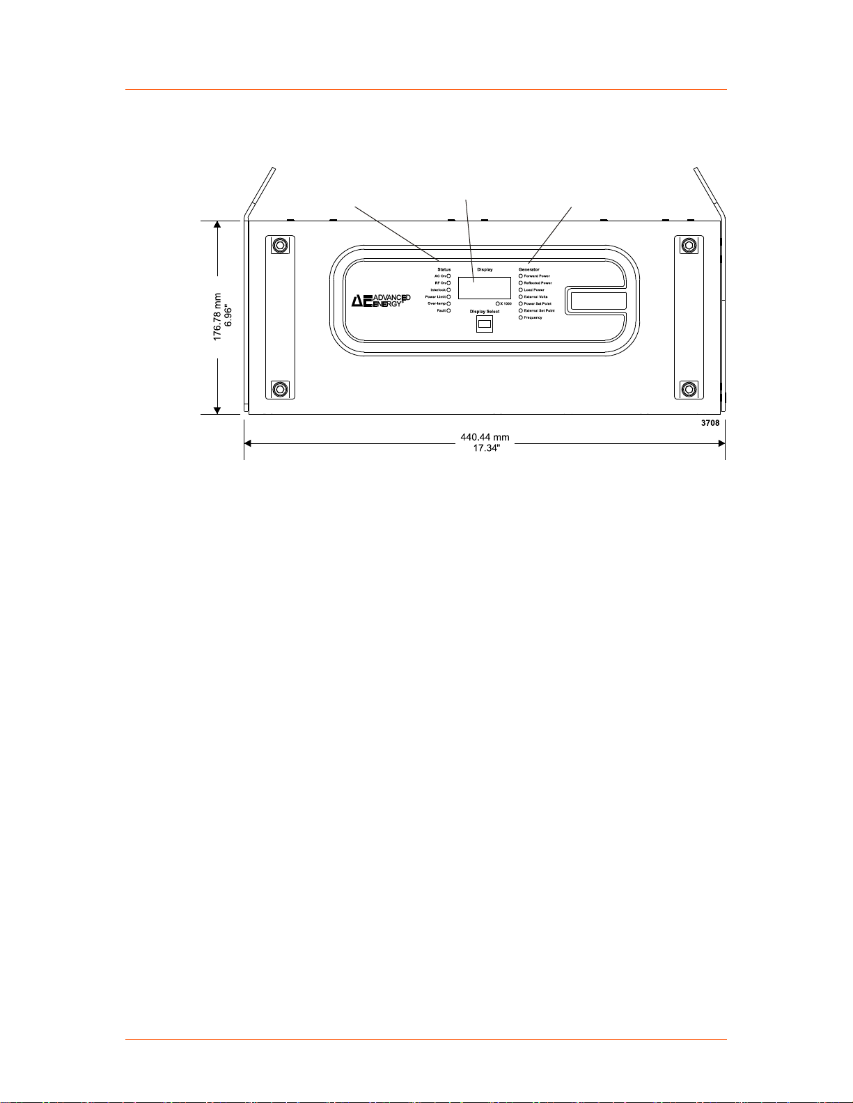
Status LEDs
Digital display
Generator LEDs
Advanced Energy
®
Unit Drawings
Paramount® MF 2 kW Generator
Figure 5‑1. Front panel
57020114-00E Installation, Setup, and Operation 5‑2
Page 100
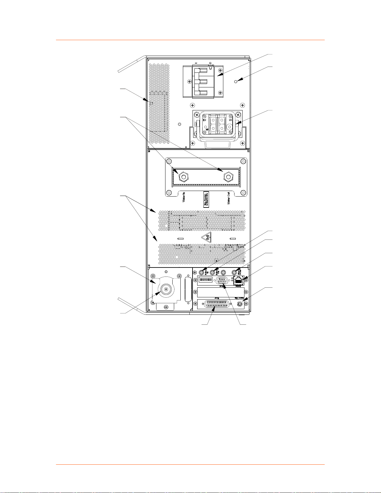
On/Off breaker
#10-32 ground stud
AC power input
(Harting connector)
SMA connector
Pulse In
SMA connector
Pulse Out
SMA connector
Bias Voltage Out
Ethernet connector
SMA connector
Sense Voltage In
25-Pin D-sub, User
9-Pin D-sub, Host
3/8 Swagelok
(female) water
cooling ports
Air intake vents
RF Output
connector
cover
RF Output
HN connector
4089
Exhaust vent
Advanced Energy
®
Paramount® MF 2 kW Generator
Figure 5‑2. Rear panel
57020114-00E Installation, Setup, and Operation 5‑3
 Loading...