

Page 1
OPERATION
MANUAL
OM3121
Revision 7
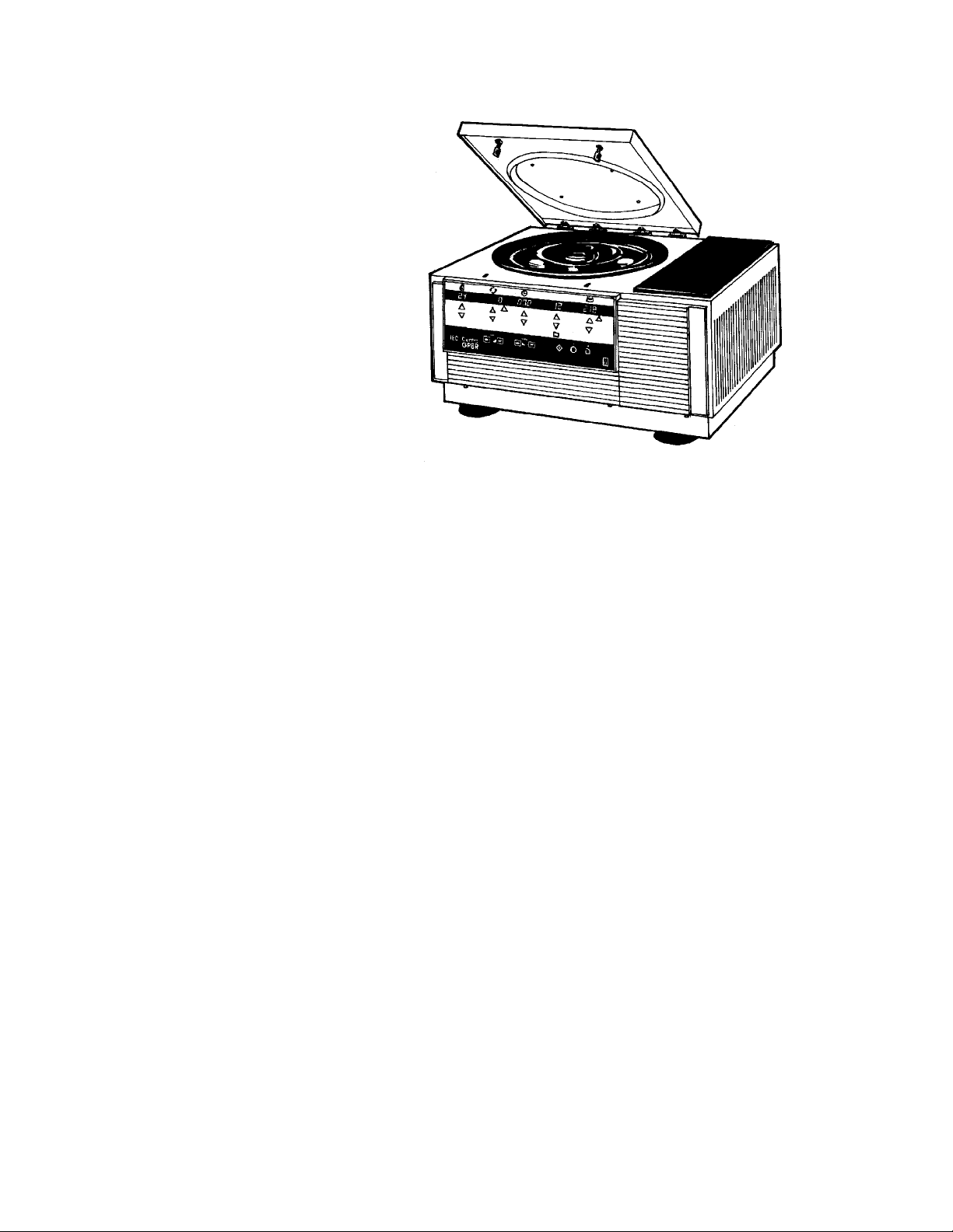
Centra-GP8
Ventilated Centrifuge
Cat. No. 3121 -- For 100/120/220/240 VAC, 50/60 Hz
Centra-GP8R
Refrigerated Centrifuge
Cat. No. 3122 -- For 120 VAC, 60 Hz
Cat. No. 3125 -- For 220/240 VAC, 50/60 Hz
Centra-GP8(F)
Ventilated Floor Model Centrifuge
Cat. No. 3127 -- For 100/120/220/240 VAC, 50/60 Hz
Centra-GP8R(F)
Refrigerated Floor Model Centrifuge
Cat. No. 3128 -- For 120 VAC, 60 Hz
Cat. No. 3129 -- For 220/240 VAC, 50/60 Hz
Artisan Technology Group - Quality Instrumentation ... Guaranteed | (888) 88-SOURCE | www.artisantg.com
Page 2

TABLE OF CONTENTS
1 INTRODUCTION .................................................................................................2
2 INSTALLATION ................................................................................................... 3
2.1 Receiving the Unit......................................................................................3
2.2 Site Preparation .........................................................................................3
Clearance Envelope .................................................................................. 3
2.3 Power Configuration ..................................................................................3
Table For Electric Configuration................................................................ 4
Voltage .......................................................................................................5
Fuses .........................................................................................................5
Power Cord ................................................................................................ 6
2.4 Moving the Unit.......................................................................................... 6
3 OPERATION....................................................................................................... 7
3.1 The Front Panel .........................................................................................7
3.2 Rotor and Accessories .............................................................................. 10
Balance ...................................................................................................... 10
Vibration ..................................................................................................... 11
Rotor Installation/Removal ........................................................................ 11
Adding Rotors ............................................................................................11
Deleting Rotors ..........................................................................................12
3.3 Starting And Stopping A Run .................................................................... 12
3.4 Operating Modes ....................................................................................... 13
Manual Operation ...................................................................................... 13
Rapid Condition (GP8R Only) ...................................................................13
Hold Mode.................................................................................................. 14
3.5 Stored Programs........................................................................................14
Locking/Recall/Add/Change ...................................................................... 14
3.6 Refrigeration (GP8R Only) ........................................................................ 15
3.7 Fail-Safe Systems ..................................................................................... 16
4 ACCESSORIES................................................................................................... 17
4.1 Speed and Force Tables ...........................................................................17
4.2 Derating Table for Dense Samples........................................................... 23
4.3 Chemical Resistance Table.......................................................................24
4.4 Decontamination Table.............................................................................. 25
4.5 Nomograph ................................................................................................ 26
5 MAINTENANCE................................................................................................... 27
5.1 Cleaning ..................................................................................................... 27
5.2 Cover Interlock Bypass .............................................................................29
5.3 Calibration.................................................................................................. 29
5.4 Brush Replacement ...................................................................................29
5.5 Warranty .................................................................................................... 30
5.6 Condition of Returned Equipment .............................................................31
5.7 Table of Spare Parts.................................................................................. 31
5.8 Fuses Not Replaceable By The Operator.................................................32
6 SPECIFICATIONS............................................................................................... 33
Centra-GP8/GP8R Operation Manual
1
Artisan Technology Group - Quality Instrumentation ... Guaranteed | (888) 88-SOURCE | www.artisantg.com
Page 3

1 INTRODUCTION
The Centra-GP8 series are general purpose centrifuges designed for use
in medical, industrial and scientific laboratories. The Centra-GP8 series is
available in the following models.
Benchtop models: 3121 - GP8 100/120/220/240 Vac, 50/60 Hz
3122 - GP8R 120 Vac, 60 Hz
3125 - GP8R 200/220/240 Vac, 50/60 Hz
Kneewell models: 3123 - GP8(K) 100/120/220/240 Vac, 50/60 Hz
3124 - GP8R(K)120 Vac, 60 Hz
3126 - GP8R(K) 200/220/240 Vac, 50/60 Hz
Floor Models: 3127 - GP8(F) 100/120/220/240 Vac, 50/60 Hz
3128 - GP8R(F)120 Vac, 60 Hz
3129 - GP8R(F)220/240 Vac, 50/60 Hz
The Centra-GP8 series can develop a maximum relative centrifugal force
(RCF) of 4630 xg using the 822A rotor. The centrifuges will accommodate
a range of centrifuge tubes and devices including 750 mL bottles,
microplates, cytological slide carriers, and microsample tubes. Maximum
sample load is 3 Liters.
Designed for ease of use, the Centra-GP8 has an ergonomic touch pad
control panel and bright, easily read LED displays. The unit can be
operated in manual mode, hold, or one of 35 programmable operations.
Programs can also be modified at run time, offering unlimited run
variations. In addition, rotor number entry permits automatic calculation of
RCF. Other features include a coast mode and separate acceleration and
deceleration controls for maintaining delicate samples such as those with
density gradients.
All refrigerated models allow you to select chamber temperatures from
-5°C to 40°C and will maintain 2°C at full speed with the 218 rotor. All
refrigerated models also offer a Rapid Condition function for pre-cooling
or pre-heating the rotor and sample chamber. Repeat runs with precisely
the same temperature, speed and time setting can be achieved with the
touch of a button.
The internal microprocessor that allows this simplified operation also
ensures repeatable results, preventing inadvertent loss of sample, and
even alerts operators when periodic maintenance is due.
The Centra-GP8 series rugged steel cabinet and rigid construction
provide quiet operation and long-term reliability coupled with impressive
safety features. A fail-safe cover interlock prevents the rotor from running
unless the cover is closed. It also prevents the cover from being opened
until the rotor has slowed to less than 90 RPM, even if the power fails. If a
load-imbalance occurs, a sensor shuts the unit down and triggers a
warning message.
2
Centra-GP8/GP8R Operation Manual
Artisan Technology Group - Quality Instrumentation ... Guaranteed | (888) 88-SOURCE | www.artisantg.com
Page 4

2.1 Receiving the Unit
IEC ships the centrifuge in a carton that protects it from shipping hazards.
Follow the unpacking instructions on the carton. Be sure to complete the
postage-paid warranty card and return it to IEC (U.S. and Canada) or to
the local distributor (Export).
2.2 Site Preparation
For benchtop units, place the unit on a smooth, clean, dry surface to
ensure that the suction feet grip firmly. The surface must be rigid, stable
and level to ensure quiet, vibration-free operation.
Clear the area beneath the unit of debris and loose material such as
paper. Allow 8 cm (3 inches) of clearance near the ventilation grill of
refrigerated units.
For Kneewell and Floor Model units, make sure that the floor is clean,
stable and level, and that the unit has at least 8 cm (3 inches) of
clearance for the GP8 and 16 cm (6 inches) of clearance for the GP8R at
the rear for ventilation.
2 INSTALLATION
Warning: Lock the front wheels before starting a run to avoid
dangerous movement. To gain access to the caster locks, pull the
centrifuge forward about 15 cm (6 inches) and then swing backwards to
swivel the casters to the front.
Section 6 of this manual provides specific dimensions and specifications
for each of the Centra-GP8 units.
Clearance Envelope International Electrotechnical Commission standard 1010 part 2-20 limits
the permitted movement of a laboratory centrifuge to 300mm in the event
of a disruption. The user should therefore mark the clearance envelope
boundary around the centrifuge, or laboratory management procedures
should require that no person or any hazardous materials are within such
a boundary while the centrifuge is operating.
2.3 Power Configuration
Do not plug in the centrifuge until you have configured the power
correctly. For best results, the centrifuges should be used on a
dedicated line. Variations in line voltage or frequency will affect the unit’s
speed and other characteristics. Less than nominal line voltage may
prevent the centrifuge from reaching published specifications of speed
and/or temperature. Also, power line voltage at some locations may sag
when the refrigeration system turns on.
Caution: Configuring the centrifuge incorrectly may damage the
equipment and will void your warranty.
Centra-GP8/GP8R Operation Manual
Artisan Technology Group - Quality Instrumentation ... Guaranteed | (888) 88-SOURCE | www.artisantg.com
3
Page 5

Table for Electric Configuration
Fuse Requirement
(all fuses are 250 V,
Slo-Blo Type T
glass 5 x 20 mm)
Power Line
Ampacity
Voltage Range
Centra-GP8 &
GP8(K/F)
100/120/220/240
50/60
3121, 3123, 3127
two
16A at
two
6.3A at
100
{
120 V
220
{
240 V
10 A
90-110 V; set 100 V
108-132 V; set 120 V
198-242 V; set 220 V
216-264 V; set 240 V
Centra-GP8R &
GP8R(K/F)
120Voltage (AC)
60Frequency (Hz)
3122, 3124, 3128Model No.
one
20A at 120 V
15 A
108-132 V
Centra-GP8R &
GP8R(K/F)
200/220/240
50/60
3125, 3126, 3129
{
200
220
two
16A at
240 V
10 A
180-220 V; set 200 V
198-242 V; set 220 V
216-264 V; set 240 V
Note: Power line ampacity requirement
effective performance.
4
Artisan Technology Group - Quality Instrumentation ... Guaranteed | (888) 88-SOURCE | www.artisantg.com
provides for sufficient current to permit
Centra-GP8/GP8R Operation Manual
Page 6
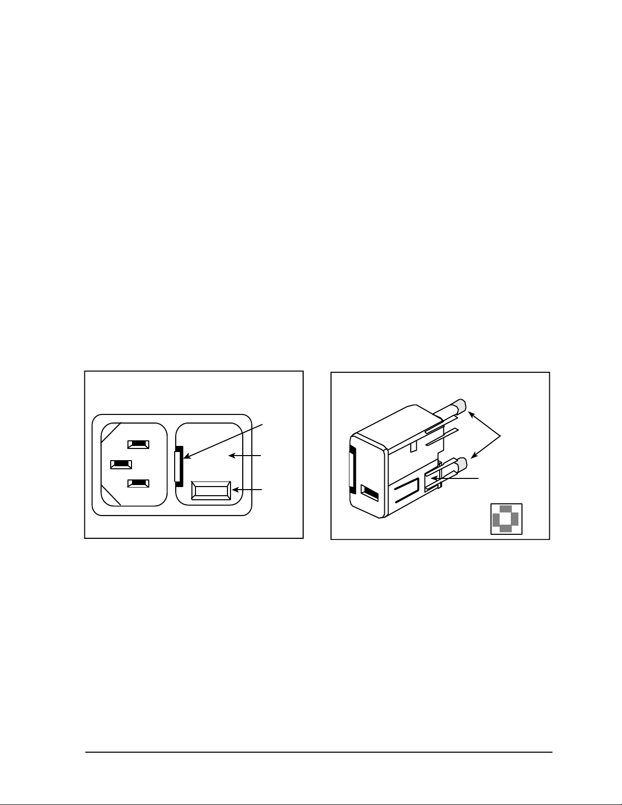
Voltage
Use a volt meter to measure the voltage at your site. For models 3121,
3123, 3125, 3126, 3127 and 3129: Locate the power entry module on the
lower left side of the unit. On the right side of the module is the fuse
drawer. A small latch on the left holds this drawer in place. Press the
latch and slide the drawer out. If the number visible in the window differs
from the voltage at your site, remove the square insert, rotate it, and
reinstall it so that the correct voltage is displayed through the window.
Fuses Install appropriate fuses for the voltage at your site.
Centra-GP8 & Centra-GP8(K) (model #3121, #3123, #3127):
two 16A fuses for 100/120 V; or two 6.3A fuses for 220/240 V.
Centra-GP8R & Centra-GP8R(K) (model #3122, #3124, #3128):
These models have no insert or window and are already configured for
use with 120V, 60 Hz only.
Centra-GP8R & Centra-GP8R(K) (model #3125, #3126, #3129):
two 16A fuses.
Ensuring that the fuses are securely in place, reinstall the entire drawer in
the side of the centrifuge.
Power Entry Module
240
POWER ENTRY MODULE
Latch
Fuse
Drawer
Voltage
Selection
Window
Fuse Drawer
Fuse
Remove and
Rotate for
Proper Voltage
FUSE DRAWER
Circuit Breaker Centrifuges are fitted with either a single pushbutton circuit breaker or a
dual pushbutton switch/circuit breaker. The dual pushbutton switch/circuit
breaker may be used as an On/Off switch for the centfuge as follows:
The circuit breakers are located in the base of the centrifuge. The dual
pushbutton swicth/circuit breaker is identified by the red and green
buttons. Pressing the green button connects power and resets the
breaker. Power may be disconnected by pressing the red button or by
unplugging the power cord from the centrifuge.
Centra-GP8/GP8R Operation Manual
Artisan Technology Group - Quality Instrumentation ... Guaranteed | (888) 88-SOURCE | www.artisantg.com
5
Page 7

Power cord
2.4 Moving the Unit
The Centra-GP8R requires a grounded power supply (3-prong power
outlet). If your facility does not have properly grounded outlets, arrange
for proper grounding.
IEC provides two power cords with each Centra-GP8 and Centra-GP8R.
One is suitable for North America, Japan and Korea. The other has bare
wires at one end so other plug types can be attached.
Caution: Do not remove the grounding pin from the centrifuge
power cord. Do not use the bare wire power cord to attach a power
plug that does not have a grounding pin. Use only the appropriate
power cord supplied by IEC.
If the bare wire power cord is used, install the selected plug and attach
the cord to the receptacle on the lower left side of the centrifuge. Plug into
the power outlet.
Warning: The power cord(s) provided with the unit is correctly rated
for the highest current demand. This power cord should not be
interchanged with cords from equipment with lower current
demand. Exchange of power cords between equipment may create
a fire hazard.
If you relocate a GP8 series centrifuge to a different power source, please
refer to section 2.3 to check the power requirements and, if necessary,
reconfigure the power.
Benchtop First, remove the rotor and accessories. Next, release the seal
on the suction cups that adhere the Centra-GP8/R to the work surface.
Lift the edge of each suction cup to release the seal and insert an object
such as a tongue depressor underneath to prevent the cup from
resealing. Position the device in its new location and check the cups to
ensure they are gripping the benchtop properly.
Kneewell To move the kneewell centrifuge, remove the rotor and accessories.
Unlock the front casters and grasp the centrifuge by its side handles and
wheel into position. Maneuver it backward to expose the locking casters
again. Lock down the casters.
Warning: Lock the front wheels before starting a run to avoid
dangerous movement.
Floor Model To move the floor model centrifuge, remove the rotor and accessories.
Unlock the front casters and grasp the centrifuge by the corners of the
cabinet and wheel into position. Maneuver it backward to expose the
locking casters again. Lock down the casters.
Warning: Lock the front wheels before starting a run to avoid
dangerous movement.
6
Artisan Technology Group - Quality Instrumentation ... Guaranteed | (888) 88-SOURCE | www.artisantg.com
Centra-GP8/GP8R Operation Manual
Page 8
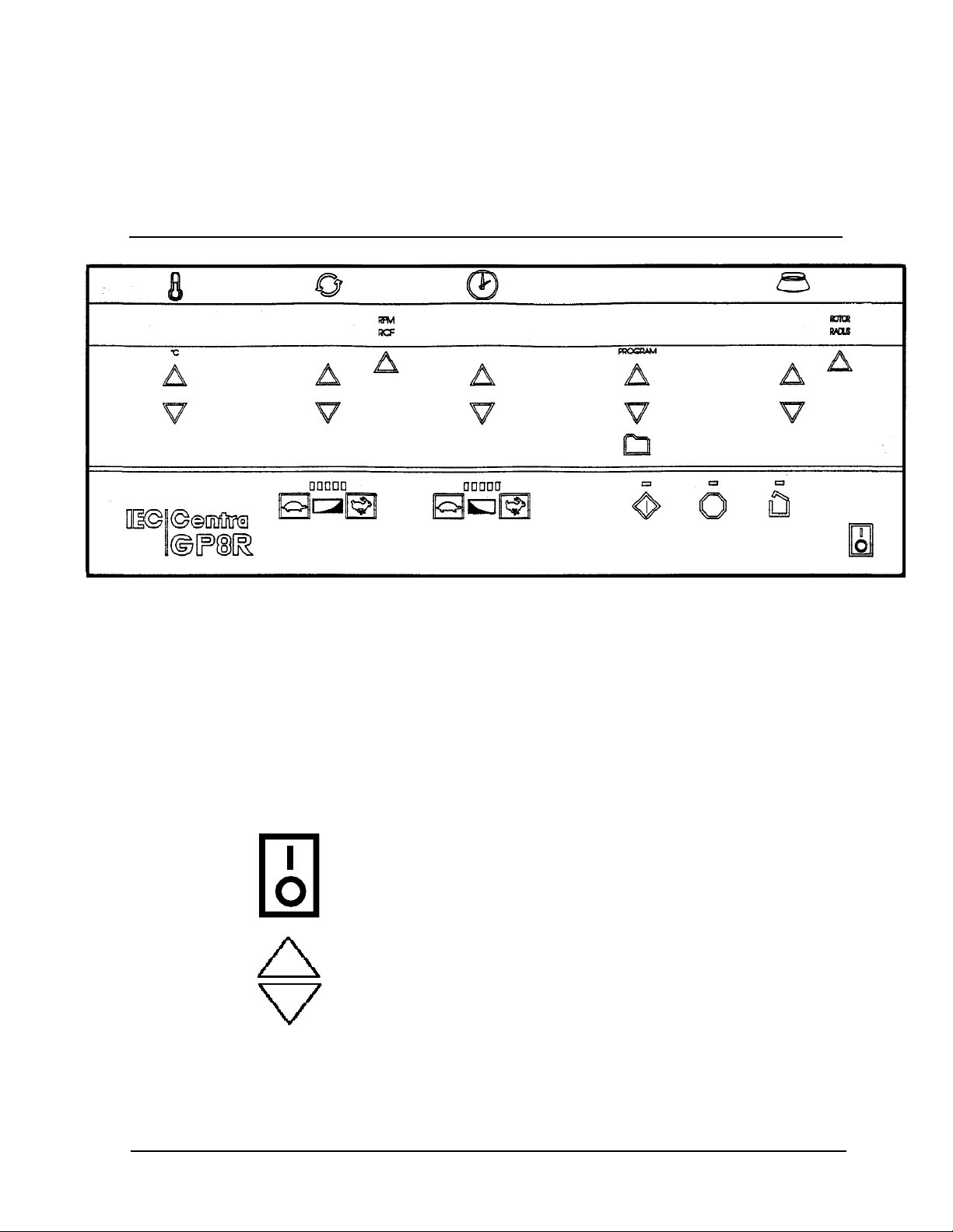
3.1 The Front Panel
3 OPERATION
FRONT PANEL OF THE CENTRA-GP8R
Run parameters are selected using the touch switches on the
control panel. An audible beep signals when a switch has been
pressed. The arrow keys are used to select the different parameters.
The Digital Display indicates both the actual and set parameters for rotor
speed or g-force, run time, chamber temperature, program number and
rotor number or rotor radius. The display normally operates at full
brightness when indicating actual run conditions. However, the display
dims when indicating set conditions, or while the arrow keys are being
used to change parameters.
The On/Off button turns on the power to the display and to the
refrigeration system (GP8R). The unit must be on to open the lid, or
operate the controls.
Arrow keys are used to view or change the desired settings for
temperature, RPM/RCF, time or rotor/radius. Pressing an arrow once
changes the display momentarily from actual readings to the program
settings. Pressing the arrow twice allows you to re-program the run
parameters. To raise or lower a setting by one increment, press and
release the appropriate arrow key. To adjust in greater increments, hold
the arrow key down and the settings will change slowly at first and then
accelerate. As you approach the proper setting, release the button and
then press it repeatedly to select the exact setting. When a button is
released for three seconds, the display returns to actual readings.
Centra-GP8/GP8R Operation Manual
Artisan Technology Group - Quality Instrumentation ... Guaranteed | (888) 88-SOURCE | www.artisantg.com
7
Page 9
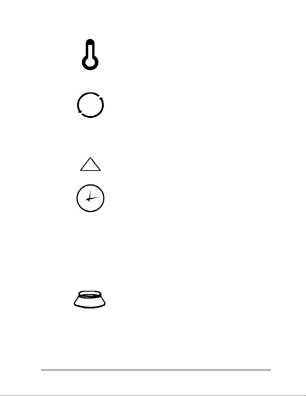
The number under this symbol represents temperature in whole degrees
Celsius. This can be set between -5 and 40°C in 1° increments. The
display range is -9 to 45° C, and the accuracy is ±1°C from 2°C to
ambient. If the actual temperature is not within 5° of the set temperature
when the run button is pressed, the run will start, a beep will sound for 1.5
seconds to alert the user, and the temperature display will alternate
between the set point and the actual temperature until the chamber
temperature is within 5° of the setting.
The display under this symbol indicates either the rotor speed (RPM), or
the Relative Centrifugal Force (RCF). Speeds are shown in increments of
10 rpm. RCF is shown in 1xg increments below 100xg and 10xg
increments above 100xg. Speed can be set between 500 and 6000 rpm
in 10 rpm increments. RCF can be set in 1xg increments up to 100xg,
and 10xg increments from 100xg to 4630xg. When entering speed, the
last digit is fixed at zero and cannot be changed. The accuracy of the
speed control is ±10 rpm.
RPM
RCF
This button toggles between RPM and RCF. When RPM is selected, the
speed indicator displays revolutions per minute. When RCF is selected,
the speed indicator displays relative centrifugal force, and the rotor/radius
indicator displays either the rotor number or the rotor radius. RCF is only
indicated when a rotor number has been selected in the rotor/radius
display.
Time can be set in 1 second intervals up to 59 seconds, 15 second
intervals from 1 to 5 minutes, and 1 minute intervals from 5 to 360
minutes. During a run, the display indicates time remaining in minutes.
Below 10 minutes, the time is displayed in minutes and seconds. The run
timing accuracy is better than 10 milliseconds.
Two timing modes are available: Acc, for countdown to start at the
beginning of acceleration; and SPd, for countdown to start when the rotor
has reached 95% of set speed. Press the time down arrow key to scroll
below zero. Acc or SPd will appear, indicating the current timing mode.
Press and release the time down arrow key to toggle between Acc or
SPd. With the correct timing mode in the time display, press the time up
arrow key to select the run time. If the time up key is not pressed at this
time, the originally programmed time will be retained. Acc and SPd only
toggle when the down key is pressed. If a program has been recalled
from memory, altered, and not saved, the manual timing mode is the
same as the original program.
The rotor/radius display indicates either the selected rotor number or the
rotor radius in centimeters. This display illuminates when the rotor is
selected. The applicable IEC rotor numbers are supplied in the memory,
along with their maximum or most common radius in centimeters. The
key under rotor/radius toggles between the two. To select a rotor
number, toggle to ROTOR and press an arrow key under the rotor
display. To change the radius, toggle to RADIUS, and press an arrow
key under the rotor display. Note that the radius cannot be changed to a
radius larger than the maximum radius for that rotor. The display
changes back to rotor number after three seconds.
8
Artisan Technology Group - Quality Instrumentation ... Guaranteed | (888) 88-SOURCE | www.artisantg.com
Centra-GP8/GP8R Operation Manual
Page 10
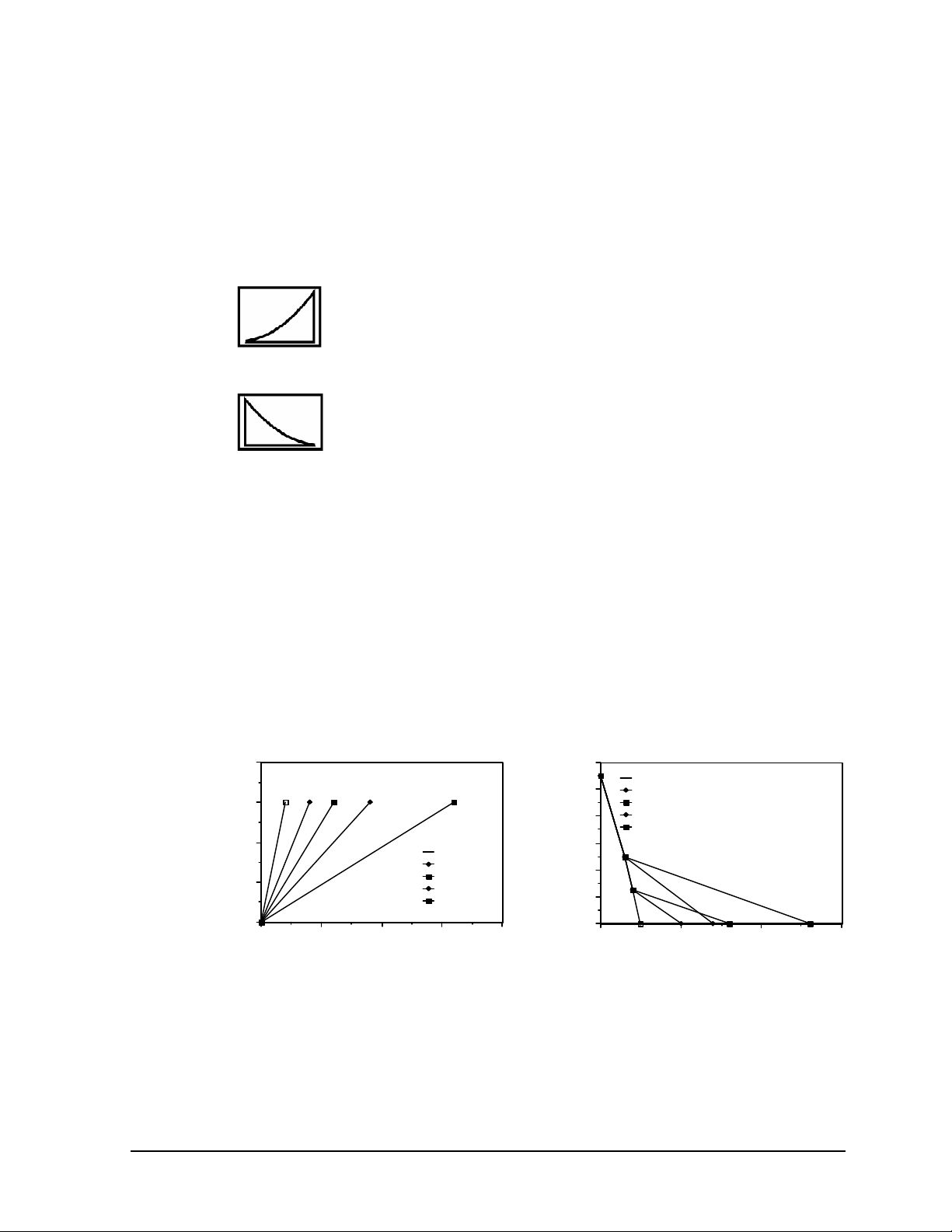
Gentle acceleration and braking can be selected when centrifuging
GP8/R Acceleration Rates
GP8/R Deceleration Rates
delicate samples. The gentle settings prevent the mixing of density
gradients and the breakup of pellets. The yellow acceleration and
deceleration mode LED’s indicate which rates have been chosen (one
LED equals setting of 1-slow; five LEDs equals setting of 5-fast).
The tortoise and hare beside this symbol control rotor acceleration to 300
RPM. After 300 RPM, acceleration is always at maximum rate. Press
the tortoise to decrease acceleration, the hare to increase. Five accel.
profiles are available, ranging from fast acceleration, when all indicators
are lit, to the slowest acceleration, when only one indicator is lit.
The tortoise and hare beside this symbol control rotor braking. Six brake
profiles are available. Press the tortoise to decrease braking, the hare to
increase. As each level is selected another indicator lights up until all
indicators are lit. The sixth profile, coast from set speed, is indicated
when all lights are out.
The profiles for acceleration and deceleration are shown in the graphs
below. Press the tortoise and hare buttons to select the rates which are
most appropriate for your application. For example, for delicate
separations, use Accel 1 (slow) and a coast mode.
Centra-GP8/GP8R Operation Manual
Artisan Technology Group - Quality Instrumentation ... Guaranteed | (888) 88-SOURCE | www.artisantg.com
RPM
400
300
200
100
0
0 10 20 30 40
Time (sec.)
Accel. 5
Accel. 4
Accel. 3
Accel. 2
Accel. 1
ACCELERATION AND DECELERATION RATES
RPM
1200
5
1000
800
600
400
200
0
0 10 20 30
Full Brake
4
Full Brake; Half Brake From 250 rpm
3
Full Brake; Coast From 250 rpm
2
Full Brake; Half Brake From 500 rpm
1
Full Brake; Coast From 500 rpm
1
2
3
5 4
Time
9
Page 11
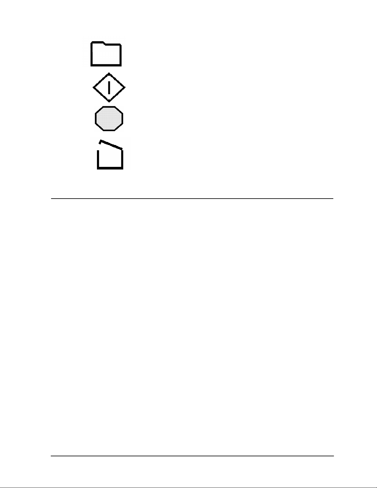
This button saves the currently displayed setting as stored program 1
through 35. (see section 3.5)
This button starts a run, using the desired settings shown on the display
panel. The associated green light blinks while the rotor approaches the
set speed. Then the light stays on until the end of the run.
This button stops the run. (A run will also stop when the set time has
elapsed.) The associated red light blinks as the rotor decelerates. (It also
blinks if an error occurs; see section 3.7) The light stays on when the
rotor stops. Three beeps signal that the rotor has stopped.
This button unlocks the cover. The button is inoperative during a run, and
the cover will not unlock until the rotor speed is below 90 rpm. The cover
must be closed to start a run. The associated yellow light is on whenever
the cover is open.
3.2 Rotor and Accessories
Balance A balanced load is essential for the safe operation of all centrifuges.
An unbalanced load produces vibration and can damage the unit. A 2
gram load imbalance, at a speed of 4600 rpm, imparts a force equivalent
to 9.1 kg at rest (20 pounds). Therefore, always make sure that the rotor
is loaded symmetrically with a full complement of accessories, and with a
full (or paired) set of tubes. Tube adapters should also be installed
symmetrically.
IEC rotors are dynamically balanced at the factory. IEC matches
removable parts (trunnion rings, shields, buckets and carriers) to within
1.0 gram, and stamps the weight on each piece. Check these markings
whenever you interchange parts to ensure that opposite parts are
matched in weight. The total weight of samples and removable parts
loaded in opposing positions must be equal in weight to within 1.0 gram.
The position numbers, present on many rotors and adapters, identify
opposing tube positions.
To obtain good dynamic balance, the opposite loads must not only be
equal in mass, but must also have the same center of gravity. Opposing
containers must be alike in shape, thickness and distribution of glass or
plastic. This is especially important for large containers. Tubes loaded
into swinging bucket rotors must likewise be symmetrical around the axis
of rotation. Verify this by rotating the entire rotor 180° by hand: the loads
should be in the same apparent positions (not in the mirror image). In
addition, the loads within each bucket must also be symmetrical around
the bucket’s pivot axis. Verify this by ensuring that each bucket is loaded
and doesn’t tilt vertically when the rotor is at rest. Maintaining balance
within each bucket ensures that the bucket and the tubes swing out
horizontally when the rotor reaches operating speed, applying centrifugal
force to the bottom of the tubes. Failure to achieve full swing-out causes
vibration, premature wear and may resuspend samples.
10
Centra-GP8/GP8R Operation Manual
Artisan Technology Group - Quality Instrumentation ... Guaranteed | (888) 88-SOURCE | www.artisantg.com
Page 12
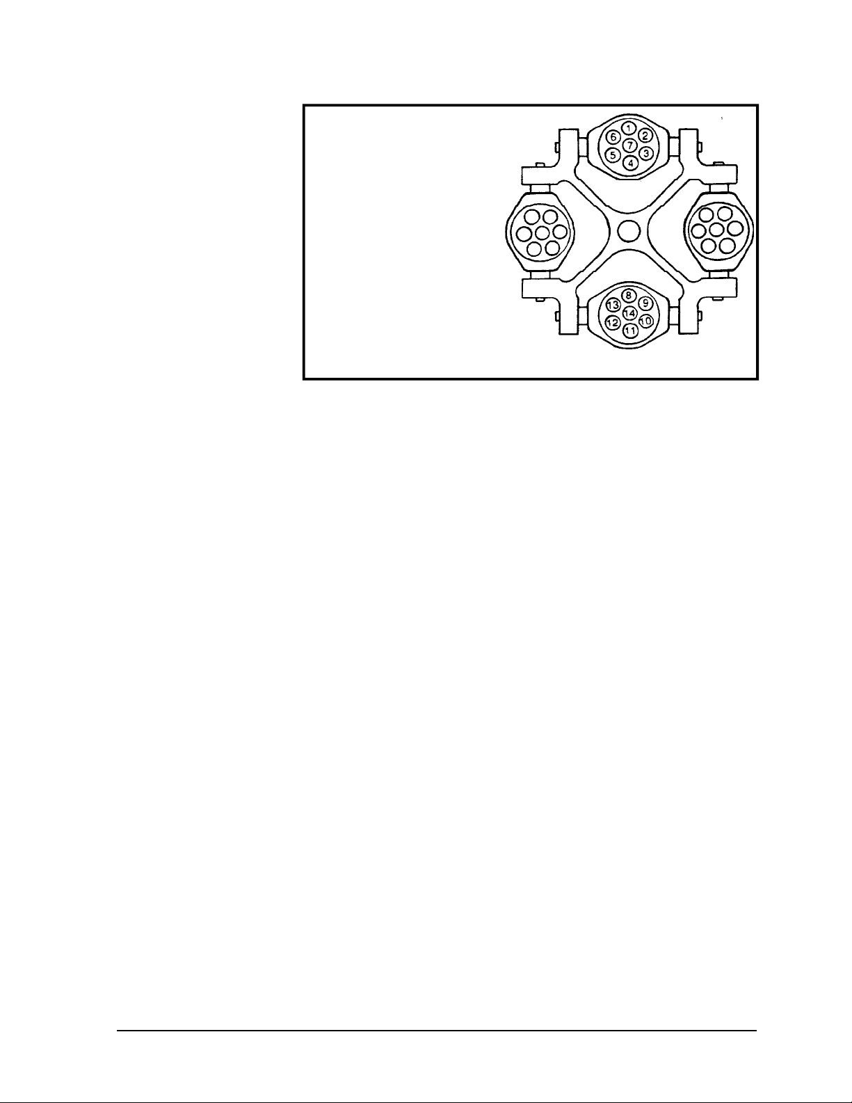
For example, load tubes in the
following manner:
1. Load four tubes.
Positions 3, 6, 10, 13
or 2,5,9,12
or 1,4,8,11
2. Load six tubes.
Positions 6,7,3,13,14,10
or 5,7,2,12,14,9
or 1,7,4,8,14,11
3. Load an odd number of tubes.
Not recommended (unless a
dummy tube is used for balance.)
Samples of different specific gravities may be processed in the same run,
provided that the samples of a given type are balanced around the rotor
as though they were the only ones in the rotor.
Vibration All centrifuges have critical speeds at which vibration occurs.
As the speed increases beyond the critical speed vibration will cease.
This inherent condition also occurs during deceleration. An imbalanced
load intensifies these critical vibrations. Do not operate this centrifuge
continuously at observed critical speeds.
Rotor Installation The rotors specified for this centrifuge are secured to the drive motor
shaft by a hex nut which is tightened or loosened with the IEC Part No.
1787 wrench, which is supplied with the machine. Before placing the
rotor onto the shaft, remove the hex nut, then be sure that the tapered
hole in the rotor and the taper of the shaft are clean. Taking care not to
damage the threads, carefully lower the rotor onto the shaft, then tighten
the hex nut to secure the rotor to the motor shaft. NOTE: Do not use
any other tool to tighten the hex nut as overtightening could occur
and the threads could be damaged.
Rotor Removal Use the IEC Part No. 1787 wrench to loosen the hex nut which holds the
rotor to the shaft. Remove the nut by turning it counterclockwise. Use
both hands to keep the rotor horizontal and pull the rotor up and off the
shaft. Periodic lubrication of the taper with BLC (see Section 5.1) will
assure easy rotor removal.
Adding Rotors As new rotors are released by IEC, the rotor number and radius can be
added to the rotor menu. To do so, press the hidden key located behind
the “C” in IEC. Prog x.x will appear. Press RPM arrows until "rotor Add"
appears. Press the file key and "Rotor" will appear next to the Rotor/
Radius display. Press an arrow key under the rotor display to select the
new rotor number. Press the file key. "Radius" appears. Use arrow keys
Centra-GP8/GP8R Operation Manual
Artisan Technology Group - Quality Instrumentation ... Guaranteed | (888) 88-SOURCE | www.artisantg.com
11
Page 13

to select maximum radius. Press file key again. "RPM" will be
illuminated. Use the RPM arrow key to select the maximum RPM for the
rotor. Push file again. Unit beeps three times to acknowledge addition of
rotor. Press "C" in IEC to return to normal operation. Note: Up to five
rotors may be added to memory. When the rotor memory is full, the unit
displays "FUL" under the rotor symbol.
Deleting Rotors Push "C" in IEC. Use RPM arrows to scroll to "rotor Add." Use the
time arrows to select "dEL" instead of "Add." Press file key. "Rotor"
appears. Use rotor arrows to select rotor to be deleted. Press file key to
delete. Unit beeps three times to acknowledge deletion of rotor.
3.3 Starting and Stopping a Run
Install as described in Section 2 of this manual. Plug in the power cord.
For models with a circuit breaker, ess the green button (see Section 2.3).
Read section 3.1 for a general description of the front panel. The desired
settings (press arrow key to display momentarily) shown on the front
panel always govern the operation of the unit. The number or symbol
displayed above the PROGRAM keys describes the operating mode of
the unit. It’s important that the unit be in the correct mode for the desired
operation (see Section 3.4).
Starting A Run Press the On/Off switch in the lower right corner of the front panel.
The Front Panel displays the set parameters for Speed, Time,
Temperature (GP8R), Program Number, and Acceleration and
Deceleration (brake) settings and rotor number current when the machine
was turned off. The stop indicator is illuminated showing that the machine
is not running. After 3 seconds the display changes to the actual
parameters.
Press the cover button to open the Centra-GP8, and install a rotor per
rotor installation instructions. To close the cover, lower the centrifuge
cover to approximately 6 inches open. With a slight flick of the wrist,
firmly push down the cover so that the resulting momentum engages the
latches. Since the GP8 series has a two-point interlock system, both
mechanisms must be fully engaged for operation to proceed. If the run
button is pressed when only one interlock is engaged, a "Lid" message
will appear in the speed display. Should this occur, close the cover
again. The yellow lid light turns off when the cover is fully latched.
Press the arrow keys twice to start changing each parameter. The key
may be pressed repeatedly or held to increment the parameter. Press
the accel or decel key to select the appropriate acceleration and braking
rates. Press START. A three beep signal sounds, the start indicator
blinks and the display changes to the set parameters. After 1.5 seconds
the run starts and the display changes back to the actual run parameters.
To view the set parameters for three seconds, press and release any
arrow key at any time during a run.
12
Stopping A Run A run will end when the set time expires, or press the stop button
to end a run and begin deceleration as selected.
Centra-GP8/GP8R Operation Manual
Artisan Technology Group - Quality Instrumentation ... Guaranteed | (888) 88-SOURCE | www.artisantg.com
Page 14

3.4 Operating Modes
The PROGRAM symbol can be one of the following operating modes:
blank: The unit is set to manual operation.
1-35: The unit is under control of the stored program with the number
shown. (see Section 3.5)
C: The unit is set to Rapid Condition.
H: The unit is set to hold mode, in which it runs until you stop it.
These digits and symbols appear above the PROGRAM arrows when the
arrows are pressed.
Whenever you change the unit’s mode of operation, the rest of the front
panel assumes the state it was in the last time that mode was selected.
Parameters may be changed during a run in manual mode or HOLD
mode. Temperature and acceleration/deceleration settings can be
changed during Rapid Condition. The centrifuge will adjust to the new run
parameters when the display changes back to run mode 3 seconds after
the last key is released.
Manual Operation Press the PROGRAM keys until the PROGRAM display is blank. Next,
select a desired temperature, rpm (or RCF, if rotor number is selected),
run time, acceleration, rotor/radius, timing and deceleration modes. Then
press START. The spin stops automatically at the end of the desired
interval. To manually stop the spin, press the STOP button.
During manual operation, the MINUTES display counts down the
remaining time in the current spin.
When the timing mode is ACC, the run time that you specify includes
acceleration time and begins when you press the START button. When
the timing mode is SPd, count down starts when 95% of set speed is
reached. Deceleration begins when the specified time elapses.
You can change the settings during a manual run to affect the run in
progress. If you change the time settings, the unit adjusts the display
countdown accordingly. If the revised run time is less than the current
time remaining, reducing the time setting may end the run. You cannot
change the unit's program, rotor/radius, or timing modes during a spin.
Rapid Condition When the chamber temperature is above the set temperature, RAPID
(GP8R Only) CONDITION will run a rotor at 500 rpm to increase air circulation in the
chamber to quickly cool the chamber to the set point. When the chamber
temperature is below the set temperature, RAPID CONDITION will run
the rotor at 3400 rpm to warm the chamber to the set temperature. When
the temperature has been reached a three beep signal will sound and the
rotor will brake to rest. (Some smaller rotors may not be able to warm the
chamber to the higher temperature settings.)
Centra-GP8/GP8R Operation Manual
Artisan Technology Group - Quality Instrumentation ... Guaranteed | (888) 88-SOURCE | www.artisantg.com
13
Page 15

Hold Mode
In HOLD mode the centrifuge will run at the current settings for speed
and temperature until the STOP button is pressed. The time display will
count up until STOP is selected. The run time display is retained until the
lid is opened and closed again. HOLD uses the current settings for
acceleration and braking. Set parameters can be changed during a run in
the HOLD mode.
3.5 Stored Programs
The Centra-GP8 series has an internal memory capable of holding 35
sets of run parameters. Each set, or program, is stored and can be
recalled by selecting a program number (1-35). Programs are retained in
memory even if the power is turned off. When necessary, a program can
be modified for a particular run or changed permanently. You cannot
change the unit's program, rotor/radius, or timing modes during a spin.
Locking Programs Programs can be locked from the program lock in the special function
menu. Press the "C" in IEC. Use RPM arrows to scroll until "Loc P" is
displayed. Use the program arrow keys to select the program to be
locked. Pressing the following keys in the following order will lock or
unlock a program: Start, Stop, Cover Open, Stop, Start and File (Save).
The display will alternate between the program number and an "L"
indicating that the values of the program are locked and cannot be
changed.
Recall Program Press a program arrow key to select the appropriate program number.
The programmed run parameters will be displayed and will become the
set parameters. To begin this run, simply press START.
Add/Change Program Select a program number with the program arrow keys. The current
program parameters will appear on the display. Modify the desired
parameters using the parameter arrow keys, or the ACCEL or BRAKE
switches. To make the changes permanent, press the PROGRAM SAVE
(file folder) key. The program number will stop flashing, and the new
program will be displayed and will remain in memory until further changes
are made. To make changes temporary, press START without pressing
the PROGRAM SAVE (file folder) key. The program display goes blank
to indicate that the values are now stored in the manual program and the
instrument is not operating from the program mode at this time. As long
as the PROGRAM SAVE (file folder) key is not pressed, the original
program remains unchanged.
14
Centra-GP8/GP8R Operation Manual
Artisan Technology Group - Quality Instrumentation ... Guaranteed | (888) 88-SOURCE | www.artisantg.com
Page 16

3.6 Refrigeration (GP8R Only)
Whenever the cover is closed and the unit is switched ON, the rotor
chamber is cooled as necessary to maintain the desired temperature
setting. However, using the keyboard so that a cold temperature is
momentarily displayed (for example, stepping through the stored
programs) does not activate refrigeration.
If a temperature higher than ambient is specified, the unit does not heat
the rotor chamber except through the normal heating effect of the
equipment (i.e. rotor air friction).
If the rotor chamber is not at the temperature specified, it does not abort
the spin. However, if the rotor chamber differs by 5°C or more from the
specified temperature at the start of a run, the unit sounds an audible
alarm. The °C display switches between the actual and programmed
temperature until the two temperatures come within 5°C. This shows the
reason for the alarm. Press the STOP button if the run should not
continue at the actual temperature.
The unit is not designed for use as a refrigerator. The natural fanning
action of the rotating horizontal and fixed angle rotors serves to maintain
a uniform temperature distribution inside the chamber. Therefore, at zero
RPM, set and actual chamber temperatures may be different.
Centra-GP8/GP8R Operation Manual
Artisan Technology Group - Quality Instrumentation ... Guaranteed | (888) 88-SOURCE | www.artisantg.com
15
Page 17

3.7 Fail-Safe Systems
Interlock: Lid cannot be opened when motor is energized or when rotor
speed exceeds 90 rpm. The lid latch is a mechanical latch opened by
momentary engagement of a solenoid. In the event of a power failure, the
door latch can be actuated with a tool for sample recovery.
User Diagnostics:
seven beeps will sound to alert the user of conditions that require
attention:
bAL This message appears in the time display when an imbalanced rotor
is run. The rotor decelerates with full brake to rest. The cover must be
opened to reset this warning.
LId This message appears in the time display If the lid is not fully closed
when START is pressed.
HEAd This message warns that a run has been started with no rotor in
the chamber. The cover must be opened to reset this warning.
PFAIL A power failure was detected during a run. Rotor will be stopped at
programmed deceleration when power is restored. This warning is
cleared by opening the cover.
bruSh This message appears (every 800 hours of use) at the end of
every run if it is time to check or change the brushes.
Error Codes:
including front panel error messages in the time display, when any of the
following conditions occur:
Warning messages will appear in the display and
Software will monitor and provide appropriate control,
16
Error 001: No tachometer
Error 002: Overspeed
Error 003: Runaway
Error 004: Chamber temperature in excess of 45°C.
Error 005: Fail-safe time-out
Error 006: COP Watchdog/Op-Code Trap error
Error 007: Stack error
Error 008: No COP - COP watchdog system not active
Error 009: Undefined interrupt
Centra-GP8/GP8R Operation Manual
Artisan Technology Group - Quality Instrumentation ... Guaranteed | (888) 88-SOURCE | www.artisantg.com
Page 18

slides
19.0
4.1 Speed And Force Tables
ROTOR 216 4-place Swinging Bucket Rotor
(includes four Cat. No. 316S buckets)
No. of
Places
148 0.25/0.4 5737
148 0.5/0.7 5737
148 5 5737
108 1.5
108767-10
36
28
28
20
12
12
8
8 100
4
4 250 5780
Tube
Volume
(ml)
5827
5827
10-20
15
40-50 5707
50
50
15
50 5703w/323
50 5704
140
5719
5719
5807
5805
5703w/7323
5704
5780
Adapter
Number
Maximum
Speed (rpm)
3400
3400
3400
3400
3400
3400
3400
3400
3400
3400
3400
3400
3400
3400
3400
3400
Max
RCF
(xg)
2400
1890
2440
1940
2440
2440
2440
2440
2070-2460
2390
2430
2460
2380
2530
2460
2550
4 ACCESSORIES
Max
Radius
(cm)
18.6
14.6
18.9
15.0
18.9
18.9
18.9
18.9
16-19
18.5
18.8
19.0
18.4
19.6
19.0
19.7
Max Tube Size
O.D. x Length (mm)
0.25/0.4 microtubes
0.5 microtubes/B-D Microtainers
12.4x91
1.5 microtubes
14.5x130
18.0x130
Falcon/Corning plastic conical
29.6x130
29.5x115
29.6x126
17.4x126
29.4x118
29.5x125
44.8x136
63.4x143
63.4x138
4
500 5781
4
750 Blood
4
Bags
Micro-
4
plates
Cyto-
4
2039
5782 2210
5799w/1024 1500
3400
3400
3400
3400
Centra-GP8/GP8R Operation Manual
Artisan Technology Group - Quality Instrumentation ... Guaranteed | (888) 88-SOURCE | www.artisantg.com
2530
2550
2520
480
19.6
19.7
19.5
17.1
77.1x145
98.3x138
Single, double pack bags
86Wx128L
25Wx75L
17
Page 19

(includes windshield cover and four Cat. No. 3218 sealed b
18.4 Microscope slides
Rotor 218A 4-place Swinging Bucket Rotor
ROTOR 218 4-place Swinging Bucket Rotor
(includes windshield, cover and four cat. no. 3218 buckets)
No. of
Places
148
108 7-10
Tube
Volume
(ml)
148
148
148 0.5 5737
108
76
76
24
28
48
24
12
12
28 40-50 5707
20 50 5805
12
12
4
4 200
4
4 250 5780
4 500 5781 4000
4
4
4
4
0.25
0.4
1.5
4
3-5
10-15
15
15
15
12 5703
15
50
40-50
140
150
225
175/225
Blood
Bags
750 - 4550
Plates
Slides 5799
Adapter
Number
5737
5737
5827
5719
5737
5827
5719
5719
5712
5712
5703
5703
5703
5780
5780
5780 4470
2077
5784
5782
Maximum
Speed (rpm)
4600
4600
4600
4600
4600
4600
4600
4600
4600
4600
4600
4600 4330
4600
4600
4600
4600
4600
4600
4600
4600
4600
4600
4600
1500
4600
4000
1500
Max
RCF
(xg)
3850
4300
4260
4140
4330
4330
4330
4330
4330
4330
4330
4400
4330
4470
4400
4400
4450
4470
4550
4550
4470
2650
460
Max
Radius
(cm)
16.3
18.2
18.0
17.5
18.3
18.3
18.3
18.3
18.3
18.3
18.3
18.3
18.6
18.3
18.9
18.6
18.6
18.8
18.9
18.9
19.2
19.2 77.3x145
18.9
19.2
14.8
Max Tube Size
O.D. x Length (mm)
0.25 microtube
0.4 microtube
B-D Microtainer
1.5/2.0 microtube
18.0x65
12.4x118
14.5x118
18.0x118
18.0x127
Falcon/Corning Conical
Falcon/Corning Conical
Falcon/Corning Conical
17.5x126
29.6x118
Falcon/Corning Conical
Falcon/Corning Conical
29.4x118
63.4x139
63.4x137
63.4x139
63.4x139
Single, double pack
98.4x140
86x128
18
Centra-GP8/GP8R Operation Manual
Artisan Technology Group - Quality Instrumentation ... Guaranteed | (888) 88-SOURCE | www.artisantg.com
Page 20
No. of
slides
19.0
- / 1024
14.8 Microscope Slides
Places
148 0.25/0.4 5737
148 0.5/0.7 5737
148 5 5737
108 1.5
108767-10
36
28
28
20
12
12
4
4 250 5780
Tube
Volume
(ml)
10-20
15
40-50 5707
50
50
15
50 5703w/323
140
Adapter
Number
5827
5827
5719
5719
5807
5805
5703w/7323
5780
ROTOR 228 4-place Swinging Bucket Rotor
(includes four Cat. No. 377S sealed buckets)
Maximum
Speed (rpm)
3400
3400
3400
3400
3400
3400
3400
3400
3400
3400
3400
3400
3400
3400
Max
RCF
(xg)
2350
1830
2390
1940
2390
2390
2390
2390
2000-2400
2340
2380
2400
2400
2500
Max
Radius
(cm)
18.2
14.2
18.5
15.0
18.5
18.5
18.5
18.5
16-19
18.1
18.4
18.6
18.6
19.3
Max Tube Size
O.D. x Length (mm)
0.25/0.4 microtubes
0.5 microtubes/B-D Microtainers
12.4x91
1.5 microtubes
14.5x130
18.0x130
Falcon/Corning plastic conical
29.6x130
29.5x115
29.6x126
17.4x126
29.4x118
63.4x143
63.4x138
4
500 5781
4
750 -
Blood
4
Bags
4
4
No. of
Places
Microplates
Cyto-
Tube
Volume
(ml)
64
48
24 15
8 50 325/320
8 50
8 Slides
5-7
10
2039
5782 2210
5799w/1024 1500
Trunnion/
Shield
Number
- / 381
- / 380
366/1013 3600 2470 17.0 16.4x133
350/323
3400
3400
3400
3400
2480
2500
2480
480
19.2
19.3
19.3
17.1
77.1x145
98.3x138
Single, double pack bags
86Wx128L
25Wx75L
ROTOR 269 Swinging Bucket Rotor
Maximum
Speed (rpm)
3400
3400
3800
3700 3030 19.8 29.4x120
1600 425
Max
RCF
(xg)
2310
2310
3200 19.8
Max
Radius
(cm)
17.9 13.6x10⁸
17.9
Max Tube Size
O.D. x Length (mm)
17.7x10⁸
30.0x145
Centra-GP8/GP8R Operation Manual
Artisan Technology Group - Quality Instrumentation ... Guaranteed | (888) 88-SOURCE | www.artisantg.com
19
Page 21
ROTOR 284 4-place Swinging Bucket Rotor
(Requires four Catalog No. 384S cups, adapters, tubes or b
19.8 63.4x144
14.2
30.0x118
3330
11.4/9.5 17.2x99
No. of
Places
Tube
Volume
(ml)
28
1.5 7228
60
48
40
28
28
16 15 7230
12
40
4
4 250
4
4
3
5
7-10
7-12
10-15
30
50
75
150
140 -
Adapter
Number
7228
7226
7236
7225
7224
7223
7231 3800
7221
7220
-
Maximum
Speed (rpm)
3800
3800
3800
3800
3800
3800
3800
3800
3800
3800
3800
3800
Max
RCF
(xg)
3080
3080
3080
3080
3080
3080
3150
3080
3080
3080
3160
3080
3200
Max
Radius
(cm)
19.1
19.1
19.1
19.1
19.1
19.1
19.5
19.1
19.1
19.1
19.6
19.1
Max Tube Size
O.D. x Length (mm)
1.5 microtube
10.9x75
12.1x137
13.3x137
16.2x137
16.2x137
17.0x130
25.5x137
29.5x135
38.1x137
52.2x143
63.4x138
ROTOR 811A Angle Rotor (45°)
No. of
Places
20 20 306
20 15 302
20 10 303 5500
20
Tube
Volume
(ml)
7
Shield
Number
356 5600
Maximum
Speed (rpm)
4600
5300
Max
RCF
(xg)
3950/
3500
4370/
3425
4260/
3620
4000/
Max
Radius
(cm)
16.7/14.8 17.2x172
13.9/10.9
12.6/10.7 17.2x114
Max Tube Size
O.D. x Length (mm)
17.2x129
ROTOR 822A Fixed Angle Rotor (45°)
No. of
Places
Tube
Volume
(ml)
12 50 305
12 50 320
Shield
Number
Maximum
Speed (rpm)
4800
5400
Max
RCF
(xg)
4025
4630
Max
Radius
(cm)
15.6
Max Tube Size
O.D. x Length (mm)
30.0x138
20
Centra-GP8/GP8R Operation Manual
Artisan Technology Group - Quality Instrumentation ... Guaranteed | (888) 88-SOURCE | www.artisantg.com
Page 22
3025
11.7
17.2x114
18.4
33.2x146
2675
14.9/10.4 17.2x10²
ROTOR 825A Angle Rotor (45°)
14.4 29.5x120
No. of
Places
Tube
Volume
(ml)
8 100 340
8 60 341
8 50 1124 4900 4080 15.2
8 50 323
Shield
Number
Maximum
Speed (rpm)
4100
4700
5100 4190
Max
RCF
(xg)
3500
4420
ROTOR 831A Angle Rotor (45°)
No. of
Places
Tube
Volume
(ml)
36 15 302
36 10 303
36 7 356 4800
Shield
Number
Maximum
Speed (rpm)
4600
5100
Max
RCF
(xg)
4090/
2175
4650/
4100
3840/
17.3/9.2 17.2x140
16.0/14.1
Max
Radius
(cm)
18.6 33.2x195
17.9
Max
Radius
(cm)
Max Tube Size
O.D. x Length (mm)
33.2x175
29.5x133
Max Tube Size
O.D. x Length (mm)
17.2x122
ROTOR 832A Angle Rotor (45°)
No. of
Places
Tube
Volume
(ml)
14
14 60 341
100
Shield
Number
340
Maximum
Speed (rpm)
4400
ROTOR 838 Angle Rotor (45°)
No. of
Places
Tube
Volume
(ml)
60 15 303
60 10 356
Centra-GP8/GP8R Operation Manual
Shield
Number
Maximum
Speed (rpm)
3700
3700
4800
Max
RCF
(xg)
3030
3980
Max
RCF
(xg)
3000/
1850
4740/
Max
Radius
(cm)
19.8 33.2x165
Max
Radius
(cm)
19.6/
7.2
18.4/
Max Tube Size
O.D. x Length (mm)
Max Tube Size
O.D. x Length (mm)
17.2x126
21
Artisan Technology Group - Quality Instrumentation ... Guaranteed | (888) 88-SOURCE | www.artisantg.com
Page 23

ROTOR 921 Swinging Bucket Rotor
Slides
- / 1024
13.8
Microscope Slides
No. of
Places
Tube
Volume
(ml)
48
36 10 - / 398
18
12
12 50 326/305 3500 2620 19.1 30.0x147
6 50 325/320 4600 4000
6 50 350/323
6 50 350/1124
6
5-7
15 355/303 3700 2690 17.6 17.2x135
50 326/320 4100
Trunnion/
Shield
Number
- / 381
Maximum
Speed (rpm)
4400
3500
4400 3680
4300
1800
Max
RCF
(xg)
3250
2290
3190
3680
500
Max
Radius
(cm)
15.0 13.6x10²
16.7
17.0
17.0
17.0
17.8
Max Tube Size
O.D. x Length (mm)
17.7x112
30.0x127
30.0x130
29.4x120
29.4x133
22
Artisan Technology Group - Quality Instrumentation ... Guaranteed | (888) 88-SOURCE | www.artisantg.com
Centra-GP8/GP8R Operation Manual
Page 24

4.2 Derating Table for Dense Samples
The Speed and Force Table lists the maximum speed for each rotor/adapter
combination in the Centra-GP8. Faster speeds impose unnecessary wear on the
motor and may cause damage to the rotor.
These speeds are guaranteed only with samples whose specific gravity is not
greater than:
1.2 for swinging bucket rotors
1.5 for fixed angle rotors
For denser samples, the maximum allowed speed is reduced (derated) by a factor
from the table below:
Derating Factor for:
Specific Gravity Swinging Bucket Fixed Angle
1.2 1 1
1.3 .960 1
1.4 .925 1
1.5 .894 1
1.6 .866 .967
1.7 .839 .939
1.8 .816 .912
1.9 .794 .888
2.0 .774 .866
2.1 .755 .844
2.2 .738 .825
2.3 .721 .807
2.4 .707 .790
2.5 .692 .774
2.6 .678 .758
2.7 .666 .744
2.8 .654 .731
2.9 .642 .719
3.0 .632 .707
Example. An angle rotor rated for 10,000 rpm, used with samples with a specific
gravity of 1.6, cannot spin faster than (10,000 x .967 =) 9,670 rpm.
Specific gravities greater than 3.0. This table is based on the formula:
...where s0 is the maximum specific gravity allowed before derating (1.2 or 1.5,
depending on the type of rotor), and sa is the actual specific gravity of the sample
in question. You can use the same formula to compute derating factors for specific
gravities greater than 3.0.
Centra-GP8/GP8R Operation Manual
Artisan Technology Group - Quality Instrumentation ... Guaranteed | (888) 88-SOURCE | www.artisantg.com
š(s0/sa)
23
Page 25
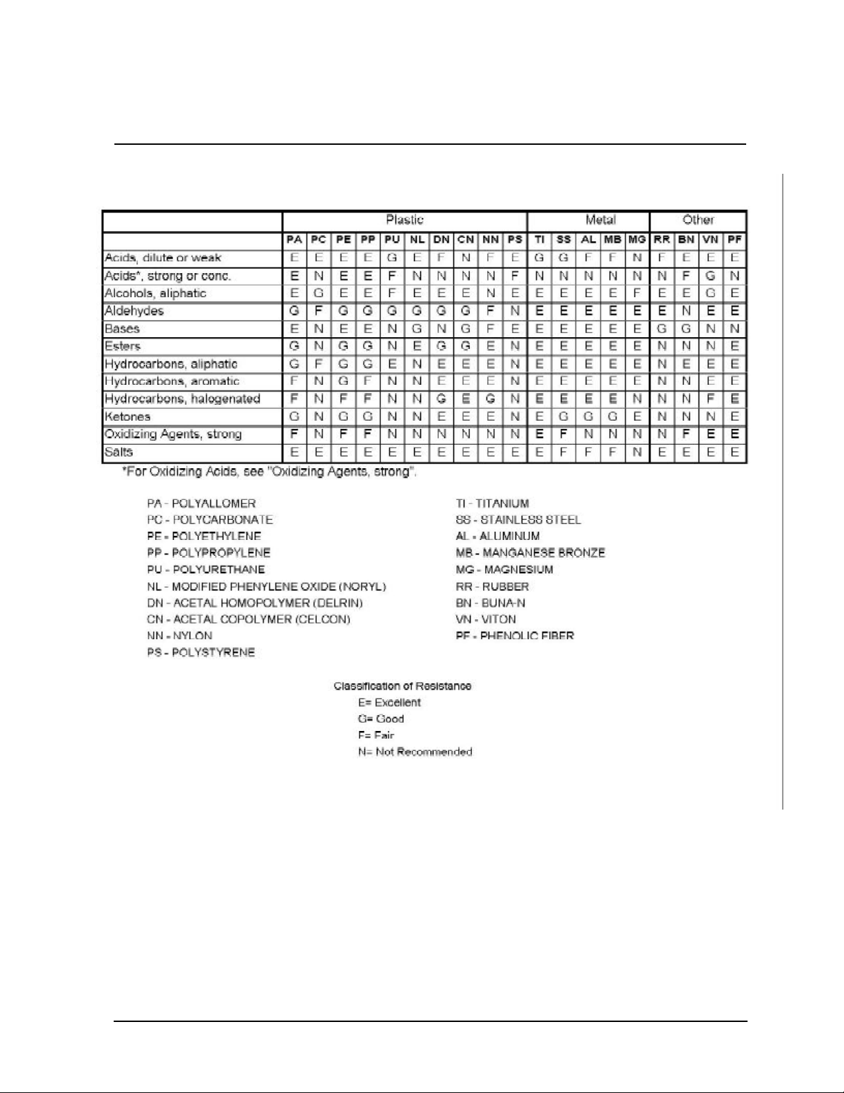
4.3 Chemical Resistance Table
24
Centra-GP8/GP8R Operation Manual
Artisan Technology Group - Quality Instrumentation ... Guaranteed | (888) 88-SOURCE | www.artisantg.com
Page 26
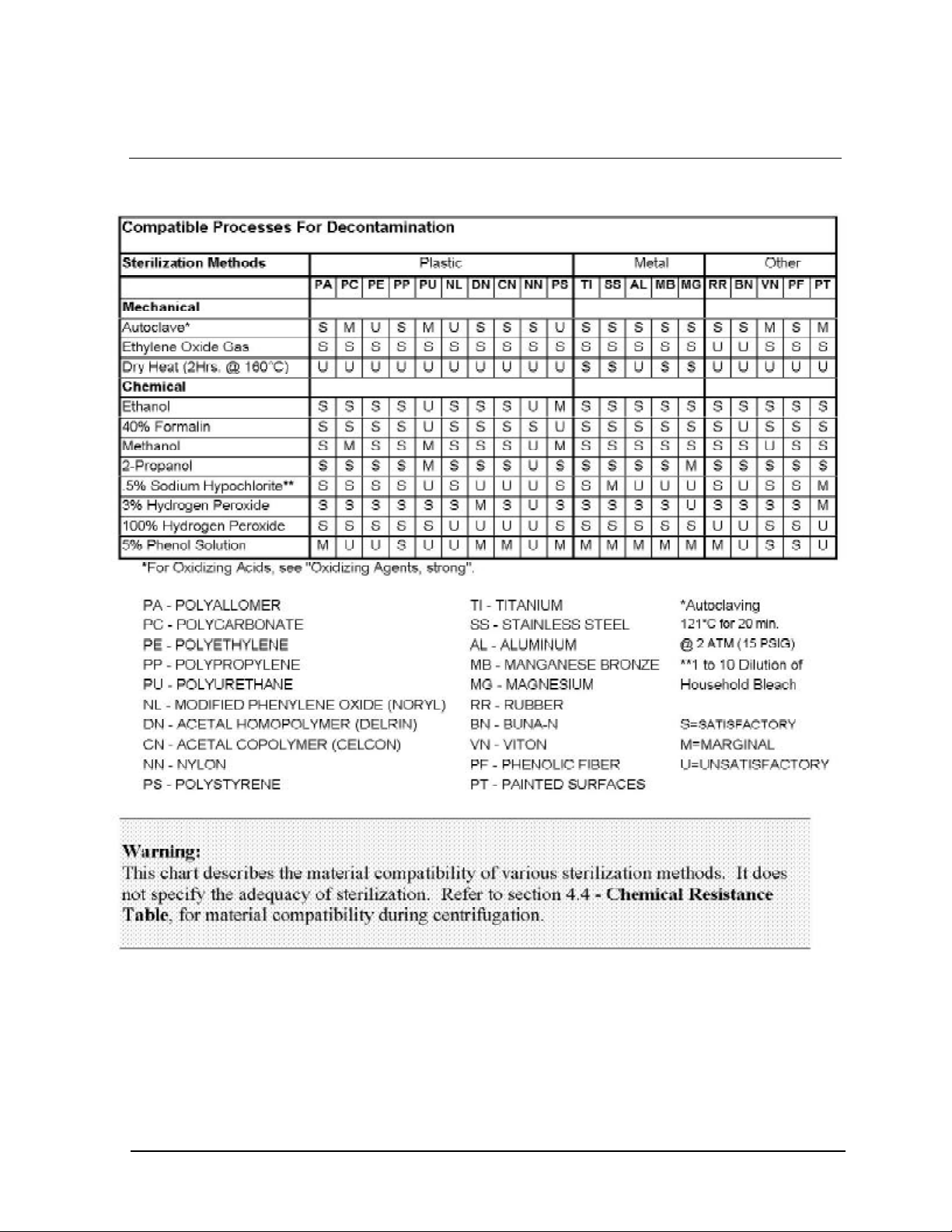
4.4 Decontamination Table
Centra-GP8/GP8R Operation Manual
Artisan Technology Group - Quality Instrumentation ... Guaranteed | (888) 88-SOURCE | www.artisantg.com
25
Page 27
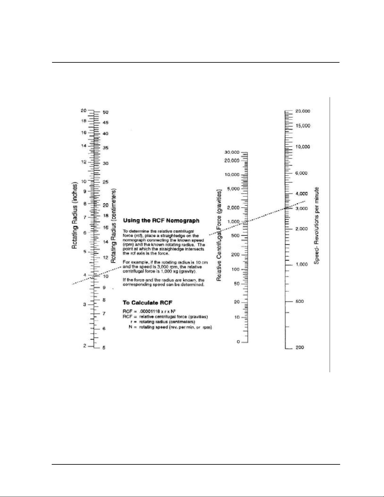
4.5 Nomograph
26
Centra-GP8/GP8R Operation Manual
Artisan Technology Group - Quality Instrumentation ... Guaranteed | (888) 88-SOURCE | www.artisantg.com
Page 28

5.1 Cleaning
5 MAINTENANCE
Keep your centrifuge clean to ensure good operation and to extend its
life. Clean the entire sample chamber, rotor, and lid at the end of each
workday, and also right after any spill.
To clean the sample chamber, use a damp sponge, warm water, and a
mild liquid detergent suitable for washing dishes by hand, such as Ivory®
liquid. Do not use caustic detergents or detergents that contain chlorine
ions, since these attack metals. Remove stubborn stains with a plastic
scrub pad. Do not use steel wool, wire brushes, abrasives, or sandpaper,
since they create corrosion sites. Never pour water directly into the
centrifuge bowl. Scrub the rotor’s tube cavities with a stiff test-tube
brush that has end bristles and a non-metallic tip. After cleaning any part,
dry it properly, preferably using a clean, absorbent towel.
If glass breakage occurs, remove all broken pieces immediately. Glass
particles, if present in the chamber, will be ground into a fine grey dust
during centrifugation. If glass breakage recurs it is recommended that all
adapters and cushions be replaced. Particles of broken glass become
imbedded in the plastic or rubber accessories. These particles can come
in contact with new glass tubes, creating a pressure point which may
result in recurring glass breakage.
Cleaning swinging bucket rotors is necessary to ensure that the
buckets can pivot freely. Periodically manipulate each bucket; if you
feel resistance or hear squeaking, lubricate all buckets with Bonded
Lubricant Coating (BLC), IEC Part No. 7133. Use the following cleaning
and lubrication procedure:
1. Wipe the old lubricant from all rotor pins and buckets with a soft,
clean, lint-free cloth saturated with solvent such as
trichloroethylene.
2. Clean the rotor and buckets as described above. The cleaning
step is important because BLC only adheres to a clean surface.
If you are unable to remove foreign matter in this way, contact an
authorized IEC Service Representative.
3. Shake the bottle of BLC vigorously until all the gray sediment at
the bottom of the bottle is dispersed.
4. Use the brush applicator cap to apply a light coating of BLC to
the bucket slots only. Do not lubricate the pins. Lubricant will
move around the pins during a spin.
5. Give the BLC 1 to 2 minutes to dry. Buff the bucket slots
vigorously with a soft, clean, lint-free cloth. Continue until no
more BLC rubs off onto the cloth. The surface will be a shiny,
light gray.
Centra-GP8/GP8R Operation Manual
Artisan Technology Group - Quality Instrumentation ... Guaranteed | (888) 88-SOURCE | www.artisantg.com
27
Page 29

Corrosion
IEC manufactures and finishes rotors and structural accessories to
give maximum resistance to corrosion. However, maximum equipment
life requires that you continually inspect the rotor cavities for corrosion,
especially after using chloride ion solutions, such as sodium chloride
(saline), and sodium hypochlorite (household bleach). These solutions
attack most metals. Clean the rotor, rotor chamber, and accessories
(particularly the sample compartments and bucket cups) thoroughly after
each such use. Inspect all surfaces under bright light for corrosion; small
crevices will grow deeper and cause failure.
If you see any corrosion, remove it immediately as follows:
1. Follow the cleaning procedure at the start of this section. Soak
the part in the mild hand-dishwashing detergent. Scrub the part
thoroughly with a stiff test-tube brush having end bristles and a
non-metallic tip.
2. Soak the part again in clear warm water for at least an hour.
3. Rinse the part thoroughly in warm water first, then in distilled
water.
4. Dry the part thoroughly with a clean, absorbent cloth.
5. If this procedure does not remove the corrosion,
discontinue use of the part.
Storage Store parts on a soft surface to avoid damaging finished surfaces.
Rotors and other parts should be clean and dry for storage. Store them
open to the atmosphere, not in a plastic bag, so that any residual
moisture will evaporate. The parts should face downward to avoid
retaining moisture in the cavities.
Decontamination Decontamination is called for if tube breakage occurs and infectious,
pathogenic, or radioactive material is released into the unit. Some rotors
totally contain the sample tubes. In this case, spillage is usually confined
to the rotor. If so, it may be sufficient to decontaminate the rotor. The
Decontamination Table lists the sensitivity of various materials to
common sterilization procedures. When using a 1-to-10 dilution of
household bleach (sodium hypochlorite) to decontaminate the chamber,
metal rotors or accessories, follow decontamination by the corrosion
cleaning procedure given earlier, since chloride ions attack most metals.
Always decontaminate for the minimum recommended time. If you
observe corrosion, remove it as described earlier, discontinue use of the
method, and use an alternate decontamination procedure.
Repeated autoclaving will seriously degrade the performance of
polycarbonate materials.
28
Centra-GP8/GP8R Operation Manual
Artisan Technology Group - Quality Instrumentation ... Guaranteed | (888) 88-SOURCE | www.artisantg.com
Page 30

5.2 Cover Interlock Bypass
If power fails, the cover remains locked. If you need to remove samples
from the unit before power is restored, use the cover interlock bypass
after the rotor has come to a stop.
Ensuring that the rotor has stopped, unplug the centrifuge. Locate a
hidden plug just below the front panel. Use a screwdriver to remove this
plug. Pull the attached cord to release the cover interlock. Listen for both
interlocks to release before opening the cover. Reassemble the plug in
the hole.
Do not perform this operation routinely. The centrifuge’s cover interlock
provides operator safety and allows the cover to be opened promptly
whenever rotation has stopped.
5.3 Calibration
The built-in, independent digital tachometer in your centrifuge is
calibrated by IEC according to standards that are traceable to the U.S.
National Institute of Standards and Technology (NIST). The built-in
tachometer uses crystal standards that do not drift. Therefore, IEC
recommends verifying the RPM indicator once every 24 months. This
can be done easily using an optical tachometer through the clear plastic
viewport in the lid. If this measurement indicates instrument tachometer
failure, please notify IEC Technical Service.
5.4 Brush Replacement
1. Unplug the centrifuge line cord. Remove rotor and accessories.
Unscrew the 6 screws retaining the motor boot and remove the boot.
2. Identify both brush caps which are located on the upper sides of the
drive motor.
3. Use a screwdriver to remove the brush caps. Be careful not to drop
any parts down into the motor chamber.
4. Carefully remove the brushes and inspect them. Each brush is
complete with a carbon contactor, a spring, a copper connector wire and
an end cap. Brush contactors should be replaced when less than 6mm
(1/4 in) long.
Caution: The commutator revolves in a counterclockwise direction as
viewed from above. If original brushes are reused, they must be inserted
in the same position from which they were removed to assure satisfactory
motor operation. The trailing edge of the brush may be identified by the
presence of a dark deposit of carbon along the side of the brush adjacent
to that edge.
Centra-GP8/GP8R Operation Manual
Artisan Technology Group - Quality Instrumentation ... Guaranteed | (888) 88-SOURCE | www.artisantg.com
29
Page 31

5.5 Warranty
6. Inspect the brush to be installed. Use IEC brushes only (part number
49801). Brushes must not be damaged or have broken copper connector
wires. The spring should not be broken. Insert each brush into the
holder and align end caps to rectangular slot. Screw in brush caps
carefully. Ensure that end caps freely engage the brush holder.
7. Replace the motor boot. Plug in centrifuge line cord.
8. Reset the brush counter. Press the hidden key located behind the "C"
in IEC on the front control panel. Use the RPM arrows to scroll through
the special functions menu until the word "brush" appears. Also
displayed will be a number indicating the hours that have passed since
the counter was last reset. Press the file key to reset this to zero. Press
the hidden key again to escape the special functions menu and return to
normal operation.
Important: When replacing brushes, order a spare set (part number
49801).
IEC wants you to be satisfied with the quality of your Centra-GP8 or
Centra-GP8R centrifuge. We guarantee your IEC centrifuge for one year
and IEC rotors for seven years. We will repair or replace any of these
products that fail, within this period from the date of its delivery, due to
defects in material and workmanship, and we will ship you the repaired
product or its replacement at our expense. You must use IEC-approved
accessories and genuine IEC spare parts. This warranty does not apply
to any instrument that has been abused or repaired without authorization.
THE FOREGOING OBLIGATIONS ARE IN LIEU OF ALL OTHER
OBLIGATIONS AND LIABILITIES INCLUDING NEGLIGENCE, AND ALL
WARRANTIES, OF MERCHANTABILITY OR OTHERWISE,
EXPRESSED OR IMPLIED IN FACT OR BY LAW. THE FOREGOING
STATES OUR ENTIRE AND EXCLUSIVE LIABILITY, AND BUYER’S
EXCLUSIVE REMEDY, FOR ANY CLAIM OR DAMAGES IN
CONNECTION WITH THE SALE OR FURNISHING OF GOODS OR
PARTS, THEIR DESIGN, SUITABILITY FOR USE, INSTALLATION, OR
OPERATION. IEC WILL IN NO EVENT BE LIABLE FOR ANY SPECIAL
OR CONSEQUENTIAL DAMAGES WHATSOEVER, AND OUR
LIABILITY UNDER NO CIRCUMSTANCES WILL EXCEED THE
PURCHASE PRICE FOR THE GOODS FOR WHICH LIABILITY IS
CLAIMED. IN SOME INSTANCES, UNITS MAY CONTAIN
RECONDITIONED (AS NEW) PARTS.
30
Centra-GP8/GP8R Operation Manual
Artisan Technology Group - Quality Instrumentation ... Guaranteed | (888) 88-SOURCE | www.artisantg.com
Page 32

5.6 Condition of Returned Equipment
Before returning equipment to IEC, you must contact IEC’s or your
dealer’s service department to obtain a return goods authorization (RGA).
All returned units must be decontaminated, free of radioactivity, and
free of hazardous and infectious materials. The RGA paperwork
includes a certificate for you to sign indicating that you have performed
these steps. IEC will not accept the shipment unless this signed
certificate accompanies it.
You must prepay transportation to the service depot.
5.7 Table of Spare Parts
GP8 and GP8(K) -- 3121, 3123 and 3127
50058 Fuse 16A (100, 120 V)
9946 Fuse 6.3A (220, 240 V)
47114 Rotor Locking Nut
1787 Rotor Locking Wrench
7133 Bonded Lubricant Coating (BLC)
49801 Brushes (pair)
43177 Line Cord (Domestic)
43312 Line Cord (International)
65436A 5/16 Magnetic Socket
GP8R and GP8R(K) -- 3122, 3124 and 3128
47114 Rotor Locking Nut
1787 Rotor Locking Wrench
7133 Bonded Lubricant Coating (BLC)
49801 Brushes (pair)
43177 Line Cord
65436A 5/16 Magnetic Socket
Centra-GP8/GP8R Operation Manual
Artisan Technology Group - Quality Instrumentation ... Guaranteed | (888) 88-SOURCE | www.artisantg.com
31
Page 33

GP8R and GP8R(K) -- 3125, 3126 and 3129
50058 Fuse 16A
47114 Rotor Locking Nut
1787 Rotor Locking Wrench
7133 Bonded Lubricant Coating (BLC)
49801 Brushes (pair)
43177 Line Cord (Domestic)
43312 Line Cord (International)
65436A 5/16 Magnetic Socket
5.8 Fuses Not Replaceable By The Operator
Three internal fuses are not replaceable by the operator.
These fuses should only be replaced by qualified service personnel.
F1 12.5A T 250V
F2 6.3A T 250V
F3 1A FAST 125V
32
Centra-GP8/GP8R Operation Manual
Artisan Technology Group - Quality Instrumentation ... Guaranteed | (888) 88-SOURCE | www.artisantg.com
Page 34

6 SPECIFICATIONS
Maximum Speed: 5600 rpm (811A angle rotor)
4600 rpm (218 windshield rotor)
3400 rpm (216 horizontal rotor)
Maximum Force: 4630 xg (822A)
Maximum Capacity: 3000 ml (216/218/228 rotors)
Refrigeration System: Sealed 1/2 hp compressor to maintain
guard bowl at 2°C at full speed with
218 rotor. Refrigerant is R-22.
Heat Output: GP8 630 Watt (2150 BTU/hr.) (typical)
GP8R 880 Watt (3000 BTU/hr.) (typical)
Power Requirements: 100,120, 220, 240VAC +/- 10%,
50/60 Hz
Dimensions: GP8 GP8R GP8R(K) GP8R(F)
a. Cover open: 36 in. 36 in. 45 in. 54 in.
b. Cover closed: 17 in. 17 in. 26 in. 35 in.
c. Width: 23 in. 30 in. 23 in. 23 in.
d. Depth: 24 in. 24 in. 27 in. 27 in.
Shipping Weight: GP8 200 lbs.
GP8R 270 lbs.
GP8(K) 240 lbs.
GP8R(K) 280 lbs.
GP8(F) 375 lbs.
GP8R(F) 375 lbs.
Ordering Information:
3121 - GP8 -100/120/220/240 Vac, 50/60 Hz, 10 A
3122 - GP8R -120 Vac, 60 Hz, 15 A
3123 - GP8(K) -100/120/220/240 Vac, 50/60 Hz, 10 A
3124 - GP8R(K) -120 Vac, 60 Hz, 15 A
3125 - GP8R -200/220/240 Vac, 50/60 Hz, 10 A
3126 - GP8R(K) -200/220/240 Vac, 50/60 Hz, 10 A
Viewport in cover for speed verification
Specifications subject to change without notice.
Centra-GP8/GP8R Operation Manual
Artisan Technology Group - Quality Instrumentation ... Guaranteed | (888) 88-SOURCE | www.artisantg.com
33
 Loading...