

Artisan 20, 53 Operators Manual
Af2.Ti5At\J®
20-53
Operators Manual
and
Spare Parts Booklet
CONTENTS
1. Application',' , '" .. 1
2.Secure operation··· , ;
3.Caution before
4.Lubrication..· , 1
5.The selection of thread···· , 2
6.Tthe Inserting of needle····..··· , 2
7.DismolJnting the bobbin case······· '" , , 2
8.Wind the bobbin case (20U33/43/53/53A163/143, 457A1B/D)···· 3
9.Tl1read the bobbin case (20U23/23D)..· '" 3
1O.Assemblage of the bobbin···· 3
11.Mounting of bobbin
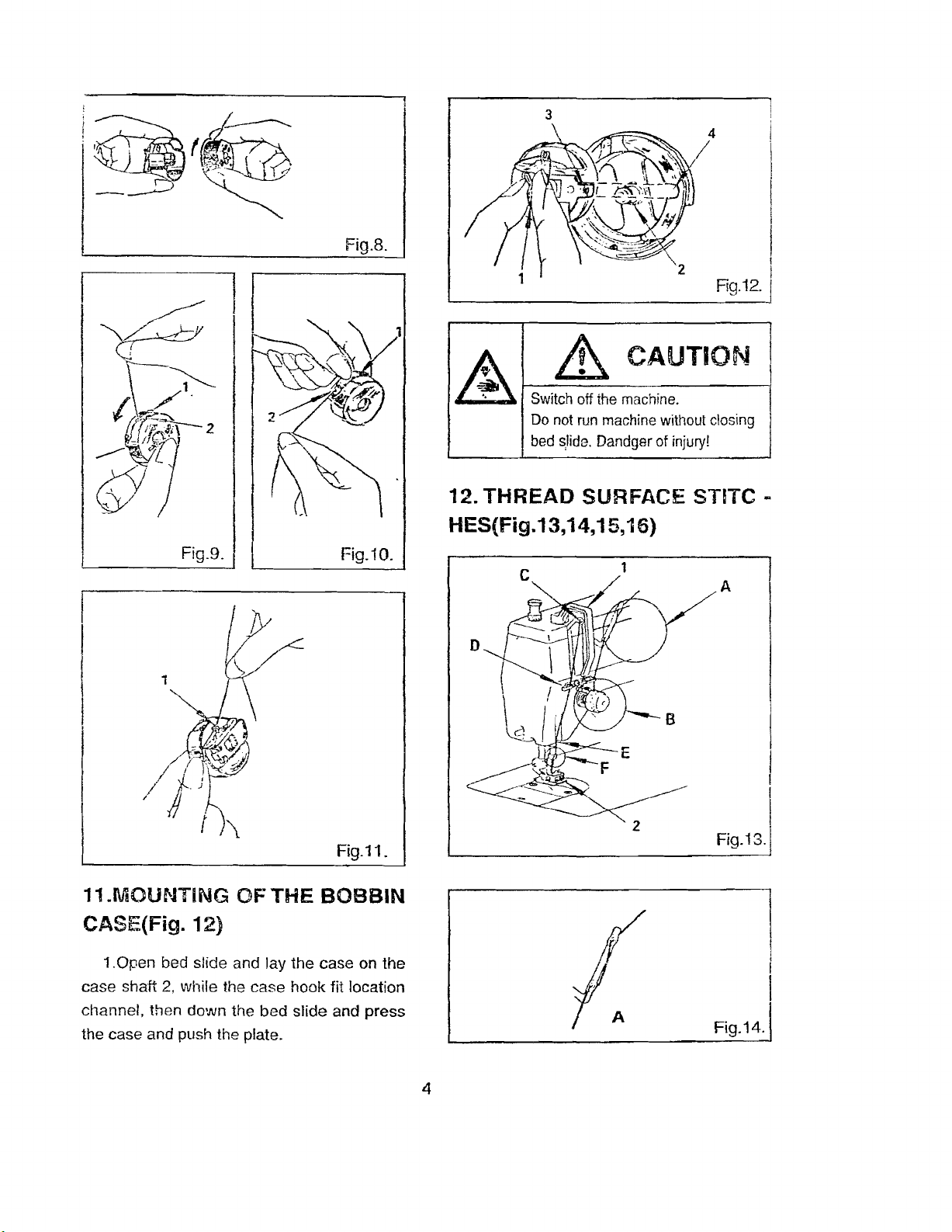
12.Thread the surface
13.Adjustment of the thread length··· ..·..·.. · 5
14.Adjustment of pressure of presser foot······
15.Adjustment of surface thread
16.Regulating the take-up
17.Adjustment of bobbin thread
operation-: '" 1
case··················
stitch·············
sprinq-: " '" ... ... ... ... 6
tension-
.. ··· 4
tension············;····
'" 4
.......•.
···· ..·..·.. 6
'" .,. 6
5
18.Needle position selection (20U33/43/53/53A163)······ '" 6
19.Horizontal needle width regulate ·.. · , ' 7
20.Locl<ing unit for linear stitching'"
21.Assemblage of belt cover· .. ··· 7
22.Mount Knee lifter (20U23/23D/33/43/143/, 457A/B/D)· 8
23.Mount Knee lifter (20U53/53A163)···.., 8
24. Mode of sewing and application of
25. Main specification ..·····..··· ..
26. The maintain of machine'" 11
·····..·······
accessories-v- , '" 9
..·..
·······..·············
..··· ..·· ..
··········
..······ 11
7
I.Ai""SJL.U""AIIUl'll
--
Zigzag embroidery stitch
..
- Pertect locl(stitch
-Extra
perfect embroidery stitch
--applicable
accurate control stitch to assure the
This
kind of
10 thin/medium/heavy material
zigzag
sewing
machine
is
2. SECURE OPERATION
1.
The
operator
understand the operation manual.
2.Whiie using it ,the
expected to do well.
3.Turn off the power or draw the
while
unfix
some
thread and no operator is on the workplace of
maintain the machine.
4.The
machine
technique.
5.While maintain the pneumatic system, the
power
checked by professional technique.
6.The power equipment should be in charge
of by professional techmique.
7.00
security adjustment method to opeerate.
Meanings
maintain
must
system
maintain
of
tile
should
of the accessories, winding
and
be do
should
the
aymbols:
be
secure
by
be
machine,
equipment is
adjustment
the
professional
shut
rtained
power
of
off
and
as
per
and
off,
the
be
the
o,
""AU
IIVI~
'. machine,do care of the following:
1.The first time for the machine work.it
should
completely.
normally or the connection box is connect well.
operator direction.
be
2.Check the power of the motor whether it
3.The
added
upper
Des-urn:.
To avoid the damage of the A
enough
wheel
should
VrE:nJo\IIVi-.
oil
to
wash
rotate
it
do
in the
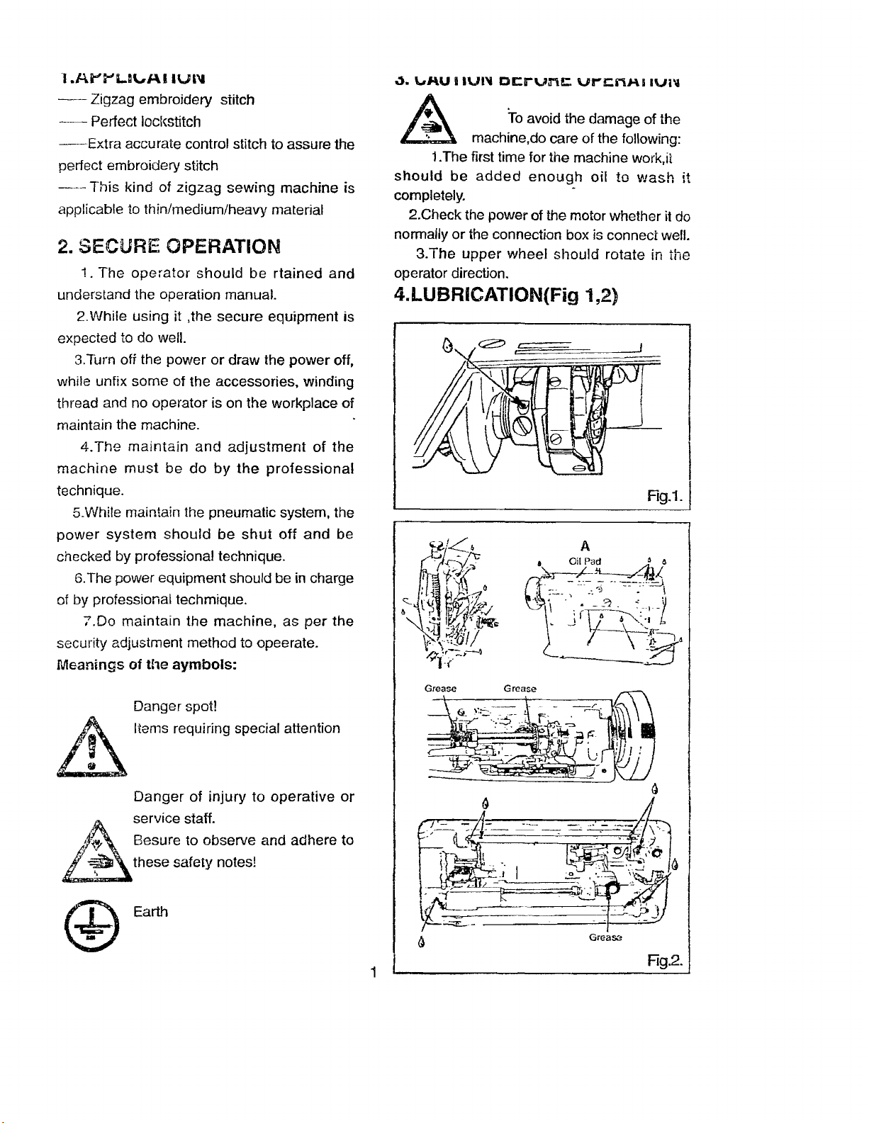
4.LUBRICATION(Fig 1,2)
Rg.i.
Danger spot!
A\
I Items requiring special attention
.
ill
Danger
service staff.
..
~
~
~
Besure to observe and adhere to
these safety notes!
'.
of
injury
to
operative
@ Earth
or
Rg.2.
1
i
.A.
Switch off the machine
Set sewing head upring again using
both hands.
I
I
Danger of crushing between sewing
Ihead and table top.
1.Rotate
,add
2.The
of oil,
3.Add
gear)
4.Pls
head.
5.Lubrication
sewing
oil.
5.THE
Select
material
tile
1-2
drip
sign
the
add
machine
SELECTION OFTHE
the
and
It. CAUTION
upper wheel to the oil
of oil.
"Q" is
little oil to
enough
oil
white
thread
refer
to
expected
the
oil to
is
advised
oil or NO.HT-7 technique
according
the
to
sign
the
sign
to
to
following.
add
"B"
"A"
use
THREAD
the
hale
1-2
(on
in
NO:2
sewing
"(;j'
drip
the
the
&. CAUTION I
Switch off the machine II
Do not operate without finger guard
(2). (See Fig.3) I
Danger of injury
the
highest
tighten
bar
and
sure
hand
screw
push
its
needle
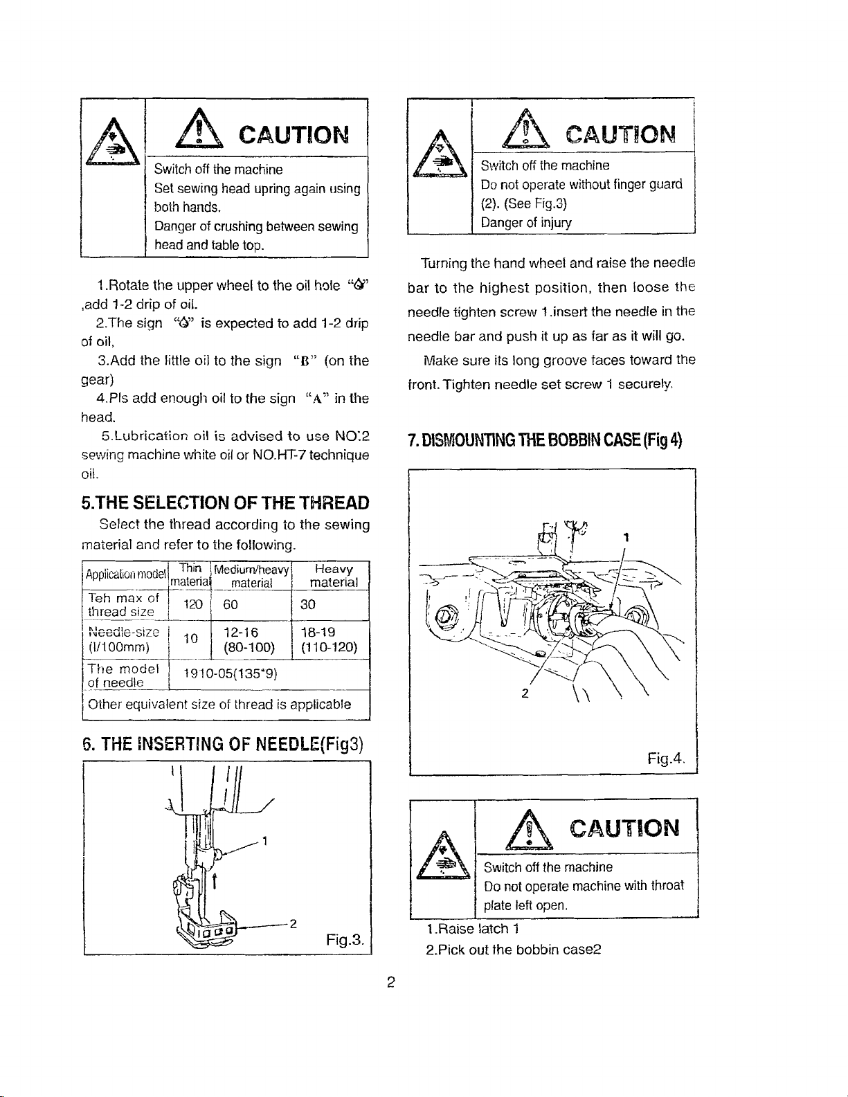
Turning the
bar
to
needle
needle
Make
front.
Tighten
7.
DISMOUNTING
wheel
position,
long
THE
and raise the
1.insert
it up as
groove
set
the
far
faces
screw
BOBBIN
then
loose
needle
as it will go.
toward
1 securely.
CASE
(Fig
needle
the
in the
the
4)
Appiic-cilion
Teh
_tbread~3.e
!Needle-size i
~1/100m?~
I
The
.()i
1Other equivalent size of thread is applicable
6.
mOdel1
.~?!~-.?-l
max
of I 120 I 60 I30
i
model
neeQle ,
THE
INSERTING
Thin.1
MediUrn!~eavy)
__
mat§nal
12-16
(80-100) I (11Q-120)
1910-05(135*9)
OF
NEEDLE(Fig3)
1----2
Heavy
matenal
08-19
Fig.3.
__
.&.
',AJ------t
t.Raise
2.Pick
Switch off the machine
Do not operate machine with throat
plate left open. I
latch 1
out
the
bobbin
CAUTION
case2
FigA
.
I
2

~.
"VaNU
(20U33/43/53/63/143, 457AlB/D)
I
til:.
tsUtst:HN
\1'''''9
1
0,0)
e.r-usn iatcruz] In
arrow
(A), bobbin winder spindle (3) rotates in
the
direction indicated by arrow (B), to
the
amount
screw(4} on latch (2) and swing
from you or
4.1f
loose
down,
toward
the
thread
the screw 5,
as required andtighten
me
of
thread
you, as required.
is
uneven
move
orrecuon mcrcateu oy
on
bobbin,loosen
the
on bobbin,
the
pre-tension up or
screw
latch
5.
adjust
away
firstly
Fig.5.
9.
(20U23/23D)
Fig.6.
I
I
A,I------------1
&. CAUTION
Do not guide or
winding
the bobbin.
110Id
thread when
shaft, push the thread adjustment plate 9, wrnd
the shuttle thread.
of
I
10.ASSEMBLAGE
1.Stop
molion screw 1, hold hand wheel with lett hand
and tUITl s!owmolion screw toward you with right
hand.
2. Place bobbin on bobbin
pushing it on as
+-----·---more tension
- ---------Iess tension
motion
needle
tar
by
loosening
winder
as it will go. pre-tension 1.
spindle 3,
stop-
into
2.(Fig.9)
1.(Fig.10)
th read
out
THREAD
THE
BOBBIN
CASE(Fig.
7)
Fig.7.
.& CAUTION
~
1.Put
2.Adjust the
the winding thread.
(FigS.9.1
1.Put the bobbin into bobbin case. Pull thread
notch 1 and
2.Draw thread
of the bobbin.(Fig.11)
Do not guide or hold thread when
windingthe
the
shuttle
screw
bobbin.
core
8, to
into
change
OFTHE
0.11)
draw
it
under
tension
out
form slot 2 on end of spring
and
pass
it
through
guide
(1),
allow
about
60mm
the
winding
the tension
BOBSiN
spring
bobbin
of
thread
case
I
I
3
4
Fig.9.
Fig.8.
Fig.10.
~
Switch off the machine. . I
Do not run machine
bed
s}ide.
12.
THREAD
HES(Fig.13,14,15,16)
CAUTION
Dandger
SURFACE STITC -
w~t~out
of
InJury!
I
I
Rg.12.!
!
I
closing i
J
11.MOUNTiNG OF
CASE(Fig. 12)
t.Open
case shaft 2, while the
channel,
the case and push the plate.
bed slide and lay
then
down
the
THE
case
bed
Fig.ii.
BOBBIN
the
case on
hook
fit location
slide
and
the
press
B
I
I
I
Fi9.13.!
(
Fig.14.
4
1'::---3
Fig.i5.
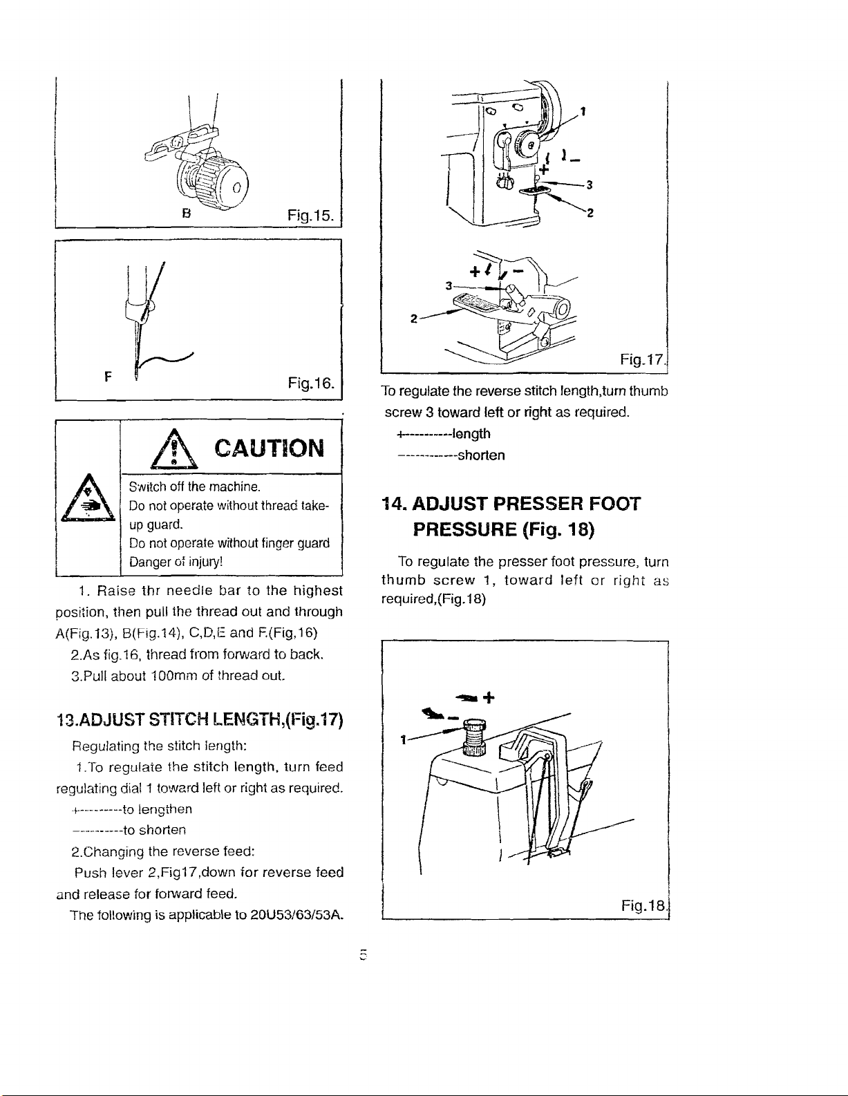
F
~
Switch off the
Do not operate without thread take-
up guard.
Do not operate without finger guard
Danger
1.
Raise
position, then pull the
A(Fig.13}, B(Fig.14), C,D,E and F.(Fig,16)
2.As
3.Pull about 100mm of thread out.
thr
needle
fig.16, thread from forward to back.
CAUTION
machine.
of injury!
bar
thread
out
to
the
and
Fig.i6.
highest
through
2
2
Fig.i7.
To regulate the reverse stitch length,turn thumb
screw
3 toward
+--------~-Iength
-----------shorten
left
or right as required.
14. ADJUST PRESSER FOOT
PRESSURE (Fig. 18)
To regulate the
thumb
required,(Fig.18)
screw
presser
1,
toward
foot pressure, turn
left
or
right
as
13.ADJUST
Regulating the stitch iength:
1.To
regulating dial 1 toward left or right as required.
+---------to lengthen
----------to
2.Changing the reverse feed:
Push lever
and release for forward feed.
The following is applicable to 20U53/63/53A.
STITCH
regulate
shorten
2,Fig17,down
the
LENGTH,(Fig.17)
stitch
length,
for
turn
reverse
feed
feed
I
Fig.i8·1
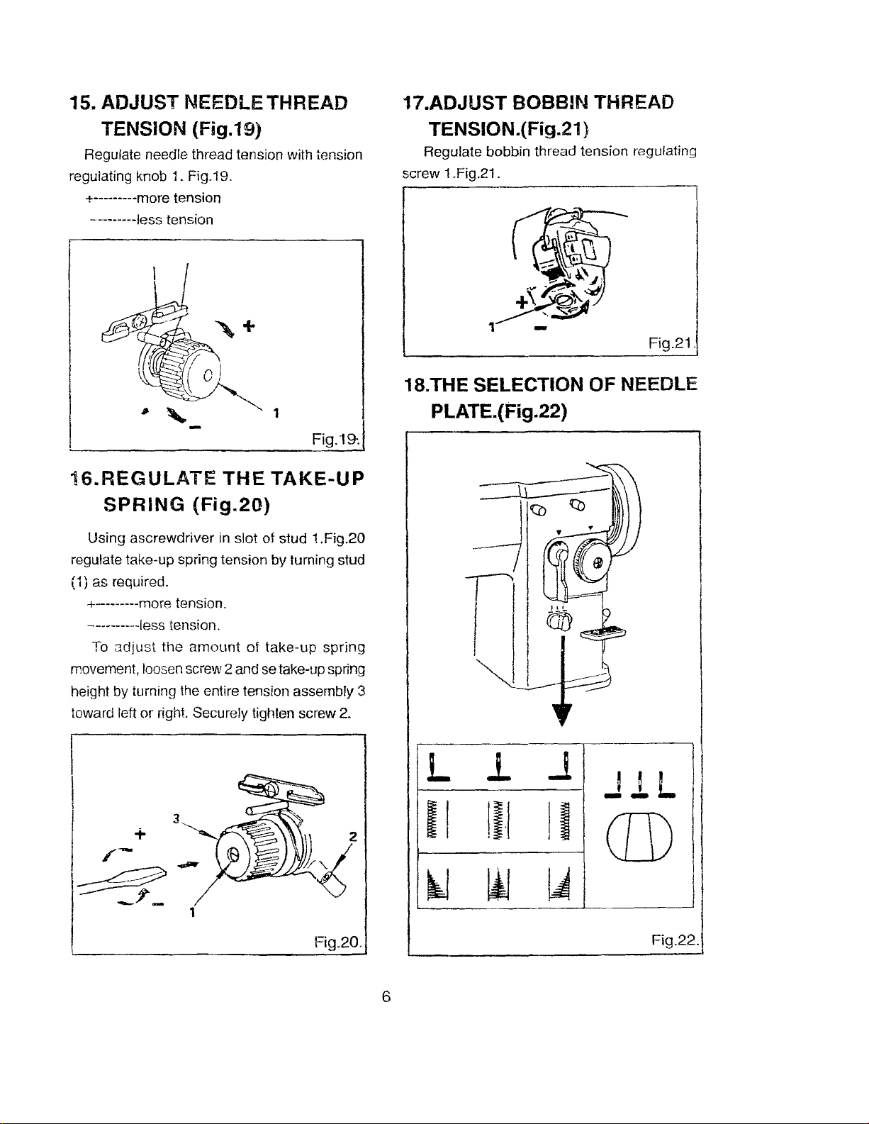
15. ADJUST NEEDLE THREAD 17.ADJUST BOBBIN THREAD
TENSION
Regulate needle thread tension with tension
reguiating knob
+---------more tension
---------les3 tension
i6.REGULATE
SPRING
Using ascrewdriver in slot of stud 1.Fig.20
regulate take-up spring tension by turning stud
(1) as required.
+--------more
----------iess tension.
To adjust the
movement,loosenscrew 2and setake-upspring
height by turning the entire tension assembly 3
toward left or right. Securely tighten screw 2.
(Fig.19)
1. Fig.19.
THE
(Fig.20)
tension.
amount
Fi9.19-·1
TAKE-UP
of take-up spring
TENSION.(Fig.21 }
Regulate bobbin thread tension regulating
screw 1.Fig.21.
l
I
Fig.21 J
18.THE SELECTION OF NEEDLE
PLATE.(Fig.22)
I
I
I
I +
I r :
I~
_?'-
L
II
~
1
Fig.20.
6
Fig.22.\
I
~
lilll-----l
I" Switch off the machine.
(20U33/43/53/53A163)
Left,right,
lockstitch and zigzag
You
the
position.
You
while the material is
I 6 CAUTION
middle
can sew the equivalent stitch ifyou
single
side
are forbid to
needle
machine.
zigzag
adjust
under
is
knob
to
the
needle
the stitch.
applicable
move
expectable
position
20.LOCKING UNIT FOR LINEAR
STITCHING (Fag.24)
to
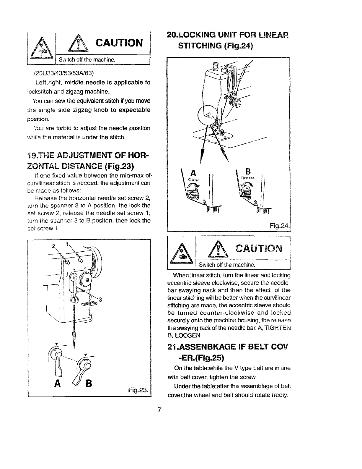
19.THE ADJUSTMENT
ZONTAL D;STANCE
If
one
fixed
value
between
curvilinear stitch is needed, the adjustment can
be
made
as follows:
Release
turn
set
screw
turn
the
set
screw
the
the horizontal needle
spanner
2, release
spanner
1.
3 to A position,
the
3 to 8 positon,
needle
Of
HOR-
(fig.23)
the
min-max
set
screw
the
lock
set
screw
then
lock
the
the
of-
2,
1;
Fig.24.
~
Switch off the machine.
When linear stitch,
eccentric sleeve clockwise, secure the needlebar
swaying
linear stitching will be better when the curvilinear
stitching are made, the eccentric sleeve should
be
turned
securely
the swaying rack of the needle bar. A,
B,
LOOSEN
nack
counter-clockwise
onto
the machine housing, the release
CAUTION
tum
the linear and locking
and
then
the
effect
and
TIGHTEN
of
the
locked
Fig.23.
21.ASSENBKAGE IF BELT COV
-ER.(Fig.25)
On the table:while the V type
with belt cover, tighten
Under
the
table;after
cover.the wheel
and
7
the
the
belt
should
belt
are in line
screw,
assemblage of
rotate freely.
belt
 Loading...