

Page 1

Installation and User Manual
4K-WISY Sensor System
Version: V45.2.3.6
Date: 2016-12-08
ODNF401EN01
Translation of the original installation and user manual.
Page 2

2
Copyright
© 2016
ARTIS GmbH
Buchenring 40
21272 Egestorf
Deutschland
www.artis.de
Page 3

3
1 General .................................................................................................................................................... 5
1.1 Information about the manual ............................................................................................................ 5
1.2 Manufacturer ...................................................................................................................................... 5
1.3 Contact details/customer service ....................................................................................................... 5
2 Safety ....................................................................................................................................................... 6
2.1 Information about safety instructions ................................................................................................. 6
2.2 Symbols and abbreviations................................................................................................................ 7
2.3 For member states of the European Union ....................................................................................... 8
2.3.1 WEEE and recycling ...................................................................................................................... 8
2.3.2 RoHS and chemicals ..................................................................................................................... 8
2.4 Transport, packaging and storage ..................................................................................................... 9
2.4.1 Transport inspection ...................................................................................................................... 9
2.4.2 Packaging ...................................................................................................................................... 9
2.4.3 Storage .......................................................................................................................................... 9
2.4.4 Ambient conditions during transport and storage .......................................................................... 9
2.5 Liability and warranty ....................................................................................................................... 10
2.6 Intended use .................................................................................................................................... 11
2.7 Warning against foreseeable misuse .............................................................................................. 11
2.8 Disturbances .................................................................................................................................... 12
2.8.1 Safety instruction ......................................................................................................................... 12
2.8.2 Behaviour in case of disturbances ............................................................................................... 12
2.9 Repair .............................................................................................................................................. 13
2.9.1 Warranty exemption ..................................................................................................................... 13
2.10 Requirements placed on user groups .............................................................................................. 14
2.11 Conditions on site ............................................................................................................................ 14
2.12 Electrical safety ................................................................................................................................ 14
3 Description ............................................................................................................................................ 15
4 Technical data ....................................................................................................................................... 16
4.1 4K-WISY-Rotor-Accu ....................................................................................................................... 16
4.2 4K-WISY Antenna Module ............................................................................................................... 18
4.3 4K-WISY-Visu .................................................................................................................................. 19
5 Installation ............................................................................................................................................. 20
5.1 Visualization software ...................................................................................................................... 20
5.2 Antenna module ............................................................................................................................... 20
5.3 Sensor .............................................................................................................................................. 21
5.4 Installation guidelines ...................................................................................................................... 22
5.4.1 Aligning the antenna module ....................................................................................................... 23
5.4.2 Positioning of the antenna module (examples) ........................................................................... 25
5.4.3 Positioning of more than one antenna module ............................................................................ 27
5.4.4 Machines positioned side by side ................................................................................................ 28
5.4.5 Alignment of the 4K-WISY-Rotor ................................................................................................. 29
5.4.6 Using the radio frequency channels ............................................................................................ 30
6 Commissioning ..................................................................................................................................... 33
6.1 Starting the visualization software ................................................................................................... 33
6.2 Logging in the rotor .......................................................................................................................... 33
Page 4

4
7 Basic settings ....................................................................................................................................... 36
7.1 Setting the visualization ................................................................................................................... 42
7.2 Setting the tool length ...................................................................................................................... 43
7.3 Setting the scaling of the visualization ............................................................................................. 44
7.4 Setting the trigger ............................................................................................................................ 44
7.5 Selecting the storage location of the report and process settings ................................................... 45
7.6 Setting the interface ......................................................................................................................... 45
7.7 Setting the rotor ............................................................................................................................... 46
8 Operation ............................................................................................................................................... 47
8.1 Process ON...................................................................................................................................... 47
8.2 Report settings ................................................................................................................................. 48
8.3 Operate ON...................................................................................................................................... 49
9 Evaluating the measurement data ...................................................................................................... 50
10 Creating a report ................................................................................................................................... 54
11 Maintenance .......................................................................................................................................... 58
12 Appendix ............................................................................................................................................... 59
12.1 Declaration of conformity ................................................................................................................. 59
12.1.1 FCC Konformitätserklärung ..................................................................................................... 59
Federal Communication Commission Interference Statement ................................................................ 59
12.1.2 Konformitätserklärung für Kanada ........................................................................................... 60
Industry Canada Statements .................................................................................................................... 60
13 Index ...................................................................................................................................................... 61
Page 5

General
5
Pos: 1 /ARTIS/Überschriften/H1/E/ÜS_ Einleitung @ 0\mod_1383142931025_1 8.docx @ 1989 @ 1 @ 1
1 General
Pos: 2 /ARTIS/Einleitung/Allgemein/Allg emein_Informationen zum Handbuch neutral formuliert (Produkt) @ 0\mod_1382 509319770_18.docx @ 1543 @ 2 @ 1
1.1 Information about the manual
The information available at the time of publishing is the base of this manual and is
deemed as correct. The manual does not claim to provide all possible details and
versions of hardware, software, installation and operation of the product. The manual
is part of the product and has to be kept accessible at any times for use by the
installation, operation, maintenance and cleaning staff.
For better representation of circumstances, the illustrations in this manual are not
necessarily to scale and may slightly vary from the actual design of the product.
All contradictory statements cease to be valid as of the date of the publication. ARTIS
GmbH reserves the right to implement changes in the interest of technical progress.
Pos: 3 /ARTIS/Einleitung/Allgemein/Allg emein_Hersteller @ 0\mod_1383135728 263_18.docx @ 1912 @ 2 @ 1
1.2 Manufacturer
The product was produced by:
ARTIS GmbH
Buchenring 40
21272 Egestorf
Germany
hereinafter called „manufacturer“ or “ARTIS”.
Pos: 4 /ARTIS/Einleitung/Allgemein/Allg emein_Kontaktdaten_Kundendienst @ 0\ mod_1383135741106_18.docx @ 1916 @ 2 @ 1
1.3 Contact details/customer service
ARTIS is a member of MARPOSS Group, which has 80 sales and marketing
companies in 23 countries. Via this sales and service network MARPOSS provides
direct and qualified customer service. Refer to the MARPOSS website for a full and
up-to-date address list: www.marposs.com
Please have the following information at hand before contacting the technical
customer service:
• Short description of the problem
• Information about machine type, machine control and operator panel of
machine
• Information about the monitoring system (type, version, possibly serial
number) and the visualization software
• Version of the sensor used.
Pos: 5 /ARTIS/Copyright/Copyright @ 0 \mod_1382511933549_18.docx @ 1559 @ @ 1
All rights reserved. No part of this document may be reproduced, stored, duplicated
and circulated or distributed in any form without the written permission of
ARTIS GmbH.
TM
Windows, PROFIBUS, PROFINET and ICP are registered trademarks.
Pos: 6 /ARTIS/Seitenumbruch/-----Seitenumbruch---- @ 0\ mod_1384520666314_18.docx @ 3570 @ @ 1
Page 6

Safety
6
Pos: 7 /ARTIS/Überschriften/H1/S/ÜS_ Sicherheit @ 0\mod_1383143060949_ 18.docx @ 1998 @ 1 @ 1
2 Safety
Pos: 8 /ARTIS/Sicherheit/Allgemein_Sich erheitskapitel (Systeme und Messumform er) @ 0\mod_1385978340400_18.doc x @ 5535 @ @ 1
Notice
Read the complete chapter Safety before installing and commissioning the system.
Thoroughly observe all safety instructions!
Compliance with all safety instructions and directives given herein is essential to
operating safety. The local regulations for the prevention of accidents and the
general safety regulations for the location, in which the machine is used, also apply.
Warning
Risk of injury!
Improper installation may cause damage of devices, injuries or death.
In order to protect human life and to ensure safe and reliable use of the product, let
only qualified personnel install and operate the device.
Pos: 9 /ARTIS/Hinweise/Sicherheitshin weise @ 0\mod_1385977551711_18.d ocx @ 5530 @ 2 @ 1
2.1 Information about safety instructions
Safety instructions point out particular dangers for persons, property and the
environment. Observe these instructions and act correspondingly. Also, pass these
instructions on to other users.
Caution
Designates instructions, which – if not observed – may result in minor or moderate
injuries of persons. Thoroughly observe the instructions in order to avoid damage to
persons.
Warning
Designates dangers, which – if not observed – may cause impairments of health,
injuries, permanent bodily damages or death. Thoroughly observe all work safety
instructions and act with caution!
Dang er
Designates electrical hazards. Non-observance of these safety instructions can
result in severe injuries or death. The relevant operations may only be carried out by
skilled electricians, who are familiar with the product.
Pos: 10 /ARTIS/Seitenumbruch/-----Seitenumbruch---- @ 0\ mod_1384520666314_18.docx @ 3570 @ @ 1
Page 7

Safety
7
Pos: 11 /ARTIS/Sicherheit/Allgemein_S ymbole & Abkürzungen @ 0\mod_138 5978894809_18.docx @ 5540 @ 2 @ 1
2.2 Symbols and abbreviations
Notice
Designates instructions, which – if not observed – may result in damage, malfunction
or failure of devices. Thoroughly observe the instructions in order to avoid partial or
total loss of devices.
The following symbols shall be used in this document.
Information
This symbol emphasizes practical tips and information. Observation of these tips
ensures efficient and trouble-free operation of the unit.
Function keys and parameters shall be emphasized using CAPITAL BOLD LETTERS.
Furthermore, the following abbreviations shall be used in our publications:
Abbreviation
Meaning
AC
Alternating current
AC Control
Adaptive Control
BA
Bridge amplifier
BN
Cutting number
DAC
Digital analog converter
DC
Direct current
DN
D number: cutting edge number
DTA
Digital torque adapter
F
Axial force
FFT
Fast Fourier Transformation
I/O
Input/output
in
Inch
lbf
Pound-force
lbs/in
Inch-pounds
MS
Microsoft
ms
Millisecond
N
Newton
Neg.
Negative
Nm
Newtonmeter
Page 8

Safety
8
Abbreviation
Meaning
OP
Operate (Feed active)
PLC
Programmable Logic Controller
PN
Program number
Pos.
Positive
PWM
Pulse-width modulation (control via frequency converter)
RF
Rapid feed
SAS
Self Adjusting System
SW
Software
T
Torque
TC
Tool change
TN
Tool number
TP
Low pass filter
Ts
Delay time
Visu
Visualization, user interface
Pos: 12 /ARTIS/Sicherheit/Allgemein_W EEE, Recycling, RoHS, Chemikalien @ 0\ mod_1382345046250_18.docx @ 121 4 @ 233 @ 1
2.3 For member states of the European Union
2.3.1 WEEE and recycling
Information
The product you bought is subject to the Directive 2002/96/EC of the European
Parliament on waste of electrical and electronic equipment (WEEE). This device
may not be disposed of with domestic waste. Please dispose of this device in
accordance with local regulations at the collecting point specified for electrical and
electronic equipment by your community or use a waste disposal company
specialized in separating waste electrical and electronic equipment.
The manufacturer is obligated to take back all the ARTIS waste equipment.
2.3.2 RoHS and chemicals
Information
The Directive 2002/95/EC of the European Parliament on the restriction of the use
of certain hazardous substances in electrical and electronic equipment prohibits the
introduction of new electrical and electronic equipment in the European market that
contains more than the maximum permitted amount of lead, mercury, cadmium,
hexavalent chromium, polybrominated biphenyls (PBB) or polybrominated diphenyl
ethers (PBDE).
Control and monitoring equipment is exempted from this requirement:
Therefore, it is not prohibited to use certain hazardous substances in monitoring
devices, tool monitoring systems and measuring transducers of ARTIS GmbH.
Pos: 13 /ARTIS/Sicherheit/Transport, V erpackung, Lagerung, Reparatur/Transport, Verpackung, Lagerung @ 0\mod_1 384437320788_18.docx @ 3450 @ 233 33 @ 1
Page 9

Safety
9
2.4 Transport, packaging and storage
2.4.1 Transport inspection
On receipt of delivery, immediately check for completeness and any transport
damage.
If transport damage can be detected externally, refuse the delivery or accept it only
with reservations. Make a note of the scope of the damage on the transport
documents/delivery note of the freight carrier and initiate a claim.
Make a claim against hidden defects as soon as they are identified because claims
for damages can only be made binding when raised within the valid claim periods.
2.4.2 Packaging
If no appropriate agreement has been made on return of the packaging material,
then it remains with the customer.
2.4.3 Storage
The following regulations apply when storing:
• Store dry.
• Do not leave packages outdoor.
• Make sure that the floor of the stockroom is dry during storage.
• Protect from direct sunlight.
• Store dust-free.
• Avoid mechanical vibrations and damages.
If storing for longer than approx. 3 months, then check the conservation measures.
In aggressive weather conditions, preservation may have to be renewed.
2.4.4 Ambient conditions during transport and storage
Name
Technical data
Ambient temperature
-20 °C – +65 °C
Temperature change
max. 5 °C/min
Relative humidity
max. 85%
Air pressure/elevation
max. 12.000 m above sea level
Condensation
none
Recovery time
2 h
Pos: 14.1 /ARTIS/Seitenumbruch/-----Seitenumbruc h---- @ 0\mod_1384520666314_18.docx @ 357 0 @ @ 1
Page 10

Safety
10
Pos: 14.2 /ARTIS/Überschriften/H2/H/ÜS_H aftung und Gewährleistung @ 1\ mod_1392216861649_18.docx @ 11162 @ 2 @ 1
2.5 Liability and warranty
Pos: 14.3 /ARTIS/Hinweise/Produktneutral e Sicherheitshinweise/Hinweis_Handbuc h vollständig durchlesen, Änderunge n vorbehalten @ 1\mod_139221657106 6_18.docx @ 11156 @ @ 1
Notice
This manual must be read carefully prior to any use of the system, notably prior to
commissioning.
The manufacturer does not accept any liability for damages or disturbances, which
originate from non-observance of the manual.
The manufacturer reserves the right of technical changes which improve the usability
or contribute to further technical development of the product.
Pos: 14.4 /ARTIS/Sicherheit/Systeme/CTM _Haftung und Gewährleistung @ 1\ mod_1392215973321_18.docx @ 11138 @ @ 1
All information and references in this user manual were compiled in consideration of
applicable regulations, the current technical engineering stage of technology as well
as our many years of findings and experiences.
Material defects are covered by the warranty with the following limitations:
• Guarantee period: The warranty covers the product and all repairs carried out
within the standard warranty terms.
• Subject of the guarantee: The warranty applies to the product and its parts
marked with the serial number or other identification number used by
Marposs.
The above warranty applies unless other agreements are reached between Marposs
and the customer.
No warranty is accepted after interference with or modifications of the product, which
were not carried out by the manufacturer!
The manufacturer accepts no liability for damages to persons or objects, which
originate from unauthorized interference with the product!
Furthermore, the obligations agreed upon in the delivery contract apply as well as
the manufacturer’s general terms and conditions and terms of delivery and the valid
legal regulations at the time of contract completion.
Pos: 15 /ARTIS/Seitenumbruch/-----Seitenumbruch---- @ 0\ mod_1384520666314_18.docx @ 3570 @ @ 1
Page 11

Safety
11
Pos: 16 /ARTIS/Überschriften/H2/B/ÜS _Bestimmungsgemäßer Gebrauch @ 4\m od_1464354352161_18.docx @ 1969 21 @ 2 @ 1
2.6 Intended use
Pos: 17 /ARTIS/Sicherheit/Systeme/4K WISY_Bestimmungsgemäßer Gebrauch @ 5 \mod_1473330686727_18.docx @ 23 3287 @ @ 1
4K-WISY is a stand-alone sensor system for collecting measurement data of rotating
tools. It includes the following components:
• 4K-WISY-Rotor-Accu: Sensor based on strain gauge technology, individually
adapted to the customer’s tool holder, integrated rechargeable battery
• 4K-WISY-Antenna Module: Antenna module with USB interface for
measurement data transfer to a PC, radio frequency 2.4 GHz
• 4K-WISY-Visu: Visualization software
• Charging unit.
The sensor system has the following functions:
• Measurement of torque, feed force and bending moment at production
machinery
• Measurement data transfer via antenna module
• Visualization of measurement data via personal computer.
Pos: 19 /ARTIS/Hinweise/Produktneutral e Sicherheitshinweise/Warnung vor vorherse hbarem Fehlgebrauch @ 0\mod_ 1382087646527_18.docx @ 1170 @ 2 @ 1
2.7 Warning against foreseeable misuse
The intended use and the specified ambient conditions have to be observed during
operation to ensure trouble-free functioning.
Any other use is explicitly excluded.
Pos: 20 /ARTIS/Sicherheit/Allgemein_St örungen @ 0\mod_1384439144328_18. docx @ 3465 @ 233 @ 1
Page 12

Safety
12
2.8 Disturbances
Only specially qualified personnel from the relevant department is authorized to
remedy disturbances of electrical installations and mechanical components.
In case of disturbances, which cannot be resolved with the measures described in
this chapter the manufacturer or an authorized service partner of the manufacturer
has to be informed.
2.8.1 Safety instruction
Warning
Improper remedy of disturbances can result in damages to persons and/or material.
Only specially qualified and authorized personnel may remedy disturbances!
2.8.2 Behaviour in case of disturbances
In general, the following applies:
1. Take the device out of service immediately in case of danger for persons,
material and/or plant safety.
2. In case of disturbances, which do not imply any of these dangers, switch off
the device via the system control. Also, interrupt the power supply of the
device and secure against being switched on again.
3. Immediately inform the responsible person on site about the disturbance.
4. Let authorized qualified personnel determine the nature, extent and origin of
disturbance and have it eliminated.
Pos: 21 /ARTIS/Seitenumbruch/-----Seitenumbruch---- @ 0\ mod_1384520666314_18.docx @ 3570 @ @ 1
Page 13

Safety
13
Pos: 22 /ARTIS/Sicherheit/Transport, V erpackung, Lagerung, Reparatur/Reparatur @ 0\mod_1384439471056_18.doc x @ 3468 @ 23 @ 1
2.9 Repair
All repairs of this device must be carried out by the manufacturer. The manufacturer
ensures a consistent high service quality, the required safety of the repaired devices
by comprehensive function and safety checks as well as the use of highly skilled
staff and suitable measuring and test equipment.
Dang er
Danger caused by electricity!
Electrical energy can cause extremely severe injuries. Damage to the insulation or to
single parts may result in danger to life. Disconnect the device from the power supply
before opening the housing.
Warning
Risk of injury from burns!
High temperatures of components in the device can persist up to approx. 10 minutes
after switching it off!
Let the device cool down to ambient temperature before performing any work on it.
Use only specified types when replacing defective fuses. Bypassing fuseholders is
forbidden!
Opening the device is only permitted to appropriately qualified staff.
2.9.1 Warranty exemption
Any liability and warranty is exempted after unauthorized tampering with and/or
modifying the device unless by the manufacturer has taken place!
The manufacturer does not take any liability for damages to persons or material,
caused by unauthorized external interference to the device by third parties!
Pos: 23 /ARTIS/Seitenumbruch/-----Seitenumbruch---- @ 0\ mod_1384520666314_18.docx @ 3570 @ @ 1
Page 14

Safety
14
Pos: 24 /ARTIS/Sicherheit/Allgemein_A nforderungen (an Benutzergruppen)_Geräte @ 0\mod_1385976259488_18.doc x @ 5525 @ 2 @ 1
2.10 Requirements placed on user groups
Warning
Danger due to improper installation!
Installation and operation require qualified personnel. Improper installation and
handling can result in damage to the devices, injuries to persons and fatal accidents.
Let only qualified, instructed and trained personnel install and operate the device.
The requirements are subdivided into the user groups:
Group/Task
Requirements
Operator/operation
Instruction by the owner operator required
Service/installation/dismantling
Qualified electrician required
Pos: 25 /ARTIS/Sicherheit/Messumformer/ Allgemein_Umgebungsbedingungen b ei Betrieb @ 0\mod_1384438442389_1 8.docx @ 3461 @ 22 @ 1
Environmental conditions
2.11 Conditions on site
Name
Technical data
Ambient temperature
0 °C – +50 °C
Temperature change
max. 0.5 °C/min
Relative humidity
max. 10% to 85%
Absolute humidity
up to max. 30 g/m3
Air pressure/elevation
max. 3.000 m above sea level
Condensation
none
Vibration
1.0 g (20 to 50 Hz)
Shock
10.0 g (10 ms)
2.12 Electrical safety
Name
Technical data
Classification
DIN EN 61326-1
Protection class
3
Pos: 26 /ARTIS/Sicherheit/Systeme/Allgem ein_Qualitätssicherung @ 1\mod_ 1392216496311_18.docx @ 11150 @ @ 1
ARTIS GmbH's and Marposs SpA’s quality control system is certified according to
DIN EN ISO 9001:2008.
Pos: 27 /ARTIS/Seitenumbruch/-----Seitenumbruch---- @ 0\ mod_1384520666314_18.docx @ 3570 @ @ 1
Page 15

Description
15
Pos: 28 /ARTIS/Überschriften/H1/B/ÜS _Beschreibung @ 0\mod_1383142851 737_18.docx @ 1986 @ 1 @ 1
3 Description
Pos: 29 /ARTIS/Beschreibung/4K_WISY/4 K-WISY Beschreibung_Blaser-S ystem @ 5\mod_1476360658501_18.doc x @ 235697 @ @ 1
Fig. 1: 4K-WISY sensor system
Properties
• Stand-alone sensor system for measurement data logging of rotating tools
• Contact-free operating principle
• Data transmission via radio
• No installation work.
The 4K-WISY sensor system includes the following components:
Component
Property
4K-WISY-Rotor-Accu
Sensor based on strain gauge technology,
attached to the customer’s tool holder, integrated
rechargeable battery
4K-WISY Antenna Module
Antenna module, USB interface for transmission
of measurement data to a PC, radio frequency
2.4 GHz
4K-WISY-Visu
Visualization software
Charging unit
The sensor system has the following functionalities:
• Measuring of torque, feed force and bending moment in production machines
• Data transmission via antenna module
• Visualization of measurement data via PC.
Pos: 31 /ARTIS/Seitenumbruch/-----Seitenumbruch---- @ 0\ mod_1384520666314_18.docx @ 3570 @ @ 1
Page 16

Technical data
16
Pos: 32 /ARTIS/Überschriften/H1/T/ÜS_T echnische Daten @ 0\mod_138314313 1843_18.docx @ 2004 @ 1 @ 1
4 Technical data
Pos: 33 /ARTIS/Überschriften/H2/ÜS_4K- WISY-Rotor-Akku @ 4\mod_1461916 132466_18.docx @ 189587 @ 2 @ 1
4.1 4K-WISY-Rotor-Accu
Pos: 35 /ARTIS/Technische Daten/Sens oren/Drehmomentsensoren/4K-WISY-R otor Technische Daten_Blaser System @ 5\mod_1475746857341_18.docx @ 2 34175 @ @ 1
Fig. 2: 4K-WISY-Rotor-Accu
4K-WISY-Rotor-Accu
Marposs Code
O3PZ1021101
Dimensions
Depending on tool-holder
Degree of protection
IP67, resistant to cooling lubricants
Surface
High tenacy, protected against abrasion by
chips
Temperature range
15 °C – 50 °C
Measuring range
Depending on the application, separate
measuring ranges for torque, feed force and
bending force, technical consultation
required!
Measuring principle
Strain gauge technology in full-bridge circuit
Resolution
16 bit
Accuracy
± 5% of measuring end value
Repetitive accuracy
± 5% of measuring end value
Data transmission rate
0.5 ms (2 kHz)
Sampling rate
0.5 ms (2 kHz)
Maximum rotational speed
n max = 1 x 10⁶/rotor diameter (mm) [rpm]
max. rotational speed = 55 m/s
Maximum transmission power
+4dBm = 2.5 mW
Maximum transmission distance
5 m , sight connection recommended
Total number of channels
70
Page 17

Technical data
17
4K-WISY-Rotor-Accu
Frequency range
2402 MHz – 2472 MHz
Charging principle
via magnetic charging plug 5 V, min. 0.5 A
Energy accumulator
Lithium polymer battery 300 mAh
Operating time
approx. 8 h
Charging time
approx. 3 h
Conformity
CE
Notice
The individual rotor properties depend on the employed tool-holder.
Pos: 36 /ARTIS/Technische Daten/Sens oren/Drehmomentsensoren/4KWisy_Hinweis e zum Akku @ 5\mod_14757395479 35_18.docx @ 234130 @ @ 1
Note
Risk of malfunction!
In order to avoid malfunction of the rotor after keeping it in the stock, thoroughly
follow the instructions concerning the integrated rechargeable battery as stated
below:
• Only store the rotor with fully charged battery.
• Recharge battery at least every 3 months.
• Fully charge battery prior to starting a measurement.
Pos: 37 /ARTIS/Technische Daten/Sens oren/Drehmomentsensoren/4KWisy_Informati onen zur Frequenzbereich @ 5\ mod_1475739402954_18.docx @ 234107 @ @ 1
Information about the radio application
Maximum transmission power
+4 dBm = 2.5 mW
Maximum transmission distance
5 m non-line-of-sight
Total number of channels
70
Frequency range
2402 MHz – 2472 MHz
A channel spacing of at least two channels is required for applications with more
than one antenna module.
Pos: 38 /ARTIS/Seitenumbruch/-----Seitenumbruch---- @ 0\ mod_1384520666314_18.docx @ 3570 @ @ 1
Page 18

Technical data
18
Pos: 39 /ARTIS/Überschriften/H2/ÜS_4K- WISY-Antennenmodul @ 4\mod_146 1919363486_18.docx @ 189676 @ 2 @ 1
4.2 4K-WISY Antenna Module
Pos: 41 /ARTIS/Technische Daten/Sens oren/Drehmomentsensoren/4K-WiSy A ntenna Module_Blaser System @ 5\mod _1476092653462_18.docx @ 234827 @ @ 1
Fig. 3: 4K-WISY Antenna Module
4K-WISY Antenna Module
Marposs Code
O830Z711001
Weight
300 g
Operating temperature
0 °C – +60 °C
Housing
Metal
Dimensions
see drawing
Degree of protection
IP30
Supply voltage
via USB, max. 200 mA
Interfaces
USB 2.0 (table top device),
digital input 0…24 V
Connecting cable
Length 2 m
Radio frequency
2.4 GHz
Conformity
CE
Pos: 42 /ARTIS/Seitenumbruch/-----Seitenumbruch---- @ 0\ mod_1384520666314_18.docx @ 3570 @ @ 1
Page 19

Technical data
19
Pos: 43 /ARTIS/Überschriften/H2/ÜS_4 K-WISY-Visu @ 4\mod_14619193874 32_18.docx @ 189699 @ 2 @ 1
4.3 4K-WISY-Visu
Pos: 44 /ARTIS/Beschreibung/4K_WISY/4 K_WISY Systemvoraussetzungen @ 4\ mod_1462264612888_18.docx @ 1 90977 @ @ 1
System requirements
• Windows 7 or higher
• 1 available USB 2.0 port
• for the installation: at least 60 MB free disk space
Pos: 45 /ARTIS/Seitenumbruch/-----Seitenumbruch---- @ 0\ mod_1384520666314_18.docx @ 3570 @ @ 1
Page 20
Installation
20
Pos: 46 /ARTIS/Überschriften/H1/I/ÜS_In stallation @ 0\mod_1383143025232_ 18.docx @ 1995 @ 1 @ 1
5 Installation
Pos: 47 /ARTIS/Installation/Systeme/4K- WISY Vorgehensweise @ 4\mod_14 61919736561_18.docx @ 189722 @ 222 @ 1
5.1 Visualization software
Copy the directory 4K-Visu into the file system on the PC.
Information
Administrator rights are required for the following steps
1 – 4.
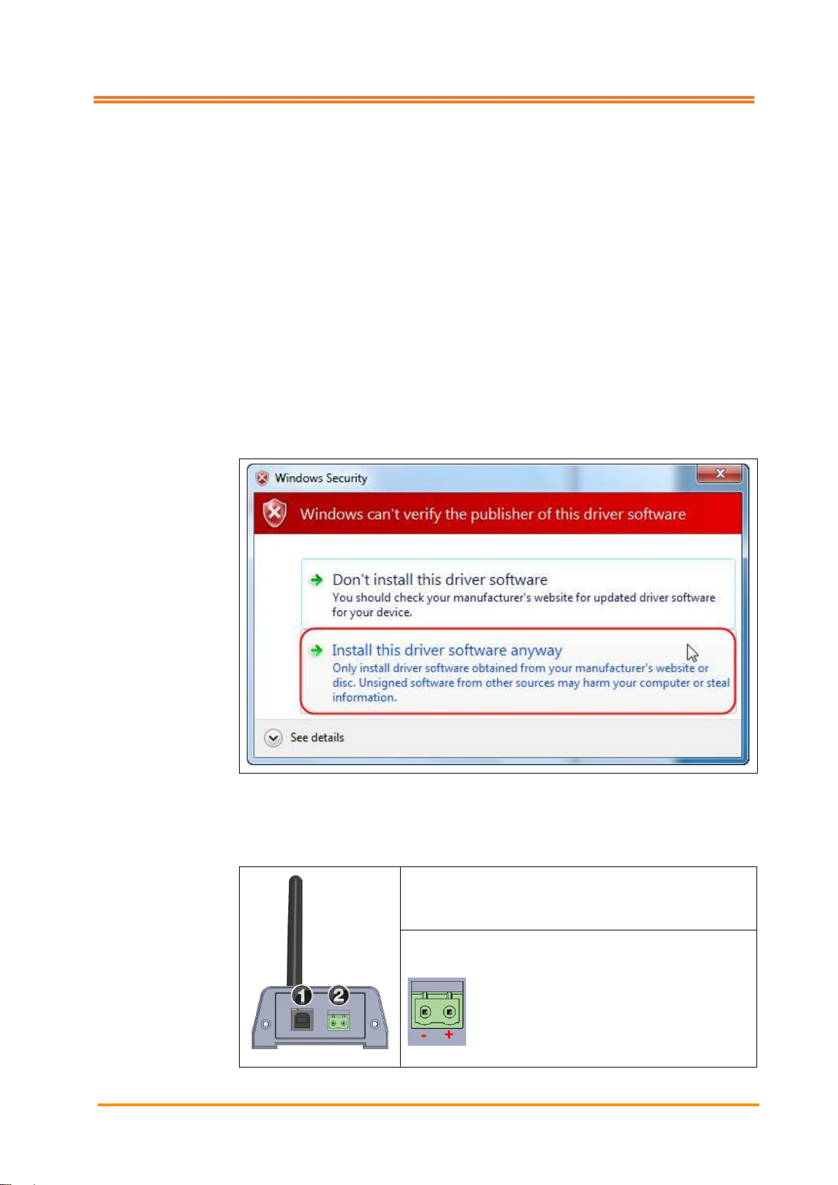
Driver installation (not required with Windows 10):
1. Do not attach the 4K-WISYAntenna Module yet
2. Open directory Driver
3. Open file Setup.bat
4. A dialog is displayed. Select second option (Install this driver software
anyway).
5.2 Antenna module
Place the 4K-WISY Antenna Module at a suitable position and connect it to the PC,
which is intended for displaying the measurement data.
USB 2.0 port
Digital input, 0…24 V
Page 21

Installation
21
5.3 Sensor
The sensor, which is designed as a cylindrical rotor, is attached to the customer’s
tool holder and firmly connected to it.
Connect the rotor (sensor) to the
charging unit using the magnetic
charging plug (figure on the left side).
Connect charging unit to a power
source.
Rotor status
The LED, which indicates the rotor status is located at the tool side of the rotor.
Meaning of the different flash cycles:
Flash-cycle (4 s)
Description
|¯|____________
Idle state: no communication, no charging
|¯|_____|¯|_____
Communication
|¯¯¯|___|¯¯¯|___
Charging
|¯¯¯¯¯¯||¯¯¯¯¯¯|
Communication and charging
Rotor off
The rotor switches off automatically after 30 minutes without communication. Push
key [sF5] Power off rotor to switch off the rotor manually.
Pos: 49 /ARTIS/Seitenumbruch/-----Seitenumbruch---- @ 0\ mod_1384520666314_18.docx @ 3570 @ @ 1
Page 22

Installation
22
Pos: 50 /ARTIS/Installation/Systeme/4K Wisy_Systeminstallation_Blaser System @ 5\mod_1476095260404_18.docx @ 234871 @ 233333 @ 1
5.4 Installation guidelines
Notice
Risk caused by moisture!
The antenna module complies with degree of protection IP30. Penetrating moisture
causes the destruction of the device. For this reason, do not install the antenna
module in the machine working area and protect it against moisture at all times.
Information
For any queries regarding the installation of the system, do not hesitate to contact
the Marposs customer service at any time.
The advantage of a radio-frequency system is the fact that communication is also
possible without being in direct line-of-sight. However, when installing a radiofrequency system, a direct communication line between transmitter and receiver
needs to be established. Only determine the final installation of the different
components after thorough tests (ranging from a few hours to several days). Also
consider the information stated below.
• All electrically conductive objects which come into contact with the system
may affect the power level.
• All metal containers reflect emitted radio waves. The machine working area
acts as Faraday Cage when its door is closed. The wavelength at 2.4 GHz is
approximately 120 mm.
• Any conductive object positioned in contact with or very close to the antenna
module or the 4K-WISY-Rotor may cause the antenna detuning.
• If the antenna module is not positioned directly in line with the 4K-WISY-Rotor,
the majority of the signal it receives has been reflected off the conductive
objects in the immediate environment (floors, ceilings, machines installed
nearby etc.)
• The immediate environment of the antenna module must be kept free from all
electrically conductive objects. This applies in particular if no line-of-sight can
be established between the 4K-WISY Rotor and the antenna module.
• The antenna module must not be fitted with any unauthorized accessories,
especially conductive material. If it is absolutely indispensable to install such
devices, please contact the customer service first.
• Evaluate the installation by performing or simulating a real working cycle.
Page 23

Installation
23
5.4.1 Aligning the antenna module
Follow the instructions stated below when aligning the antenna module:
Correct alignment
Install the antenna module on an even
surface on a wall and not inside a cavity or
any enclosure. Do not use any other
antenna or cable extension with the antenna
module.
Wrong alignment
A hemispherical space around the antenna
module must be kept free from all electrically
conductive objects (radius of the
hemisphere 500 mm).
Guarantee a direct path between the
antenna module and the 4K-WISY-Rotor,
even while parts are being machined.
Keep the immediate environment of the
antenna module free from all electrically
conductive objects.
Page 24

Installation
24
Correct alignment
An imaginary cone (having a hypotenuse
equivalent to 500 mm) projected in front of
the antenna module must be kept free from
all electrically conductive objects. The cone
shall be defined by a vertex positioned at the
center of the receiver contact plane and a
minimum angle of aperture of 90°.
Wrong alignment
The dimensions indicated above represent the minimum requirements. The quality
of communication improves if the free space beyond these limits increases.
Page 25

Installation
25
5.4.2 Positioning of the antenna module (examples)
Use below schematic drawing of the typical work environment of a machine tool for
understanding how to position the antenna module(s) optimally.
Fig. 4: Typical work environment of a machine tool
and in the figure below show typical ways of positioning the antenna
module(s).
Fig. 5: Typical ways of positioning the antenna module
Page 26

Installation
26
With emission direction to the 4K-WISY-Rotor
With emission direction parallel to the input direction of the machine window
These are just guidelines.
NEVER install antenna modules at the following positions:
• Inside metal structures
• Inside deep niches
• Directly in front of metal walls preventing the emission of radio waves to the
front of the receiver.
Correct positioning
Antenna module has
direct visibility toward the
4K-WISY-Rotor.
Communication takes place
correctly.
Correct positioning
Typical configuration if
antenna module and
4K-WISY-Rotor have no line-
of-sight.
Transmission takes place
through reflections of the
radio waves off floor, ceiling,
walls and other objects in the
area.
There must always be a
window (without metal grille)
for access to the radio waves
on the machine walls
because the metal walls
screen them.
The emission direction of the
4K-WISY-Rotors is parallel to
that of the window on the
machine so (after a few
reflections) the radio signal
can reach the antenna
module.
Page 27

Installation
27
For the following reasons, the conditions proposed in the second example (antenna
module ()) are more critical than the ones proposed above (antenna module ()):
1. The radio transmission path is longer.
2. The antenna module is exposed to external interferences (e.g. Wi-Fi®,
Bluetooth®).
3. The machine structure acts as an obstruction to transmission, rather than
shielding it from interferences.
4. Staff, who passes close to the machine or approaches it with other radio
transmission systems may interfere with the connection.
5. It is very important to ensure that the maximum transmission distance does
not exceed 5 m.
6. The antenna module should not be installed as in the drawing below if the
door is fitted with a metal grille.
5.4.3 Positioning of more than one antenna module
More than one antenna modules close to each other must be positioned in such a
way that the antennas do not interfere mutually.
Correct positioning
The two antenna modules
are installed at a sufficient
distance to each other;
mutual interferences do not
occur.
Ensure minimum distance
of 0.5 m between two
antenna modules!
Wrong positioning
The two antenna modules
are installed too close to
each other; mutual
interferences occur.
The radiation diagrams
change and sufficient
transmission quality in the
direction necessary for
entering the machine is not
ensured.
Ensure minimum distance
of 0.5 m between two
antenna modules!
Page 28

Installation
28
5.4.4 Machines positioned side by side
Correct positioning
The two antenna modules and are positioned correctly. Although they
receive the signal from the corresponding 4K-WISY rotors 1 and 2 only after it has
been reflected off the machine positioned in front of them, they also receive the
signal directly from the opposite transmitter. Cross-interferences can be
eliminated by using the appropriate channels.
Page 29

Installation
29
5.4.5 Alignment of the 4K-WISY-Rotor
The 4K-WISY-Rotor radiation diagram is practically circular in a plane lying
perpendicular to the transmitter axis. The intensity of radiation is at its maximum
level in this plane. Although the system will function correctly when using reflected
transmission paths, it is preferable to use the transmission direction recommended
below. Optimal alignment is attained when using the 90°-extension for the rotor.
Recommended solution
Milling machine. The
predominant radiation
directions of 4K-WISY-Rotor
and antenna module
coincide.
Non recommended
solution
Milling machine. The
predominant radiation
directions of 4K-WISY-Rotor
and antenna module do not
coincide.
Notice
Risk of significant attenuation of the radio signal!
Metal objects and other electrically conductive materials may affect the performance
of the antenna and result in attenuation of the radio signal.
Avoid these negative influences by reducing the number of metal objects near the
4K-WISY-Rotor to a minimum and keep the rotor and the antenna module free from
chips and coolants during operation.
Pos: 51 /ARTIS/Seitenumbruch/-----Seitenumbruch---- @ 0\ mod_1384520666314_18.docx @ 3570 @ @ 1
Page 30

Installation
30
Pos: 52 /ARTIS/Installation/Systeme/Ver wendung von Funkfrequenzkanälen @ 5 \mod_1475822350401_18.docx @ 23 4442 @ 3 @ 1
5.4.6 Using the radio frequency channels
2.4 GHz ISM band
The 4K-WISY system uses the internationally reserved 2.4 GHz ISM-Band
(Industrial-Scientific-Medical) band which occupies the following frequency range:
• 2402 MHz – 2472 MHz (worldwide)
The 4K-WISY system emitted power is approximately +4 dBm (~2.5mW) which
means that it is classified as a class 2 transmission device. There are currently
numerous wireless systems which use this frequency range (2.4 GHz). So it is very
important to ensure that there is sufficient space available in the frequency spectrum
for the system to function reliably.
1. 4K-WISY channels
The 4K-WISY system features 70 frequency channels each occupying a bandwidth
of 2 MHz. To convert the channel number into the effective frequency range, use the
following formula:
Effective frequency = 2400 MHz + channel number x 1MHz
Selecting the most suitable working channel for each radio system is very important
for guaranteeing constant and reliable communication. When compared to other
systems such as FHSS (Frequency Hopping Spread Spectrum), 4K-WISY has the
advantage that it enables users to plan and allocate the way the frequency spectrum
is used by selecting and defining the channels.
If there are multiple systems in the same area (factory) it is possible to re-use
channels provided the correct distance is maintained.
Distance
Example
a) Minimum distance between antenna
module and 4K-WISY-Rotor (using
different channels)
0.5 m
27A 0.5 m 43A
b) Minimum distance before re-allocating
any given frequency channel
100 m
27A 100 m 27A
A. Machine with single antenna module installed
The most frequently used application consists of a machine equipped with a spindle
and one 4K-WISY antenna module. In this configuration, it is possible to use a
different frequency channel for each system installed.
B. Multiple antenna modules installed on a single machine
In the case of machines equipped with dual spindles, in order to measure two parts
simultaneously it is necessary to install an antenna module for each spindle. In this
configuration it is important to ensure that:
• The minimum distance between the devices is respected
• The antenna modules are positioned as far apart as possible
• Identical or adjacent frequency channels are avoided.
C. Installation with two or more machines positioned close together
Given the unpredictable way in which electromagnetic waves are propagated, the
machines must never be treated as though they are isolated systems; in other words,
whenever a radio frequency system is installed, it will influence and be influenced by
all the other machines that are installed around it.
Page 31

Installation
31
The 4K-WISY system has a wide communication range. Therefore, two machines
installed with a few meters of each other should be treated as a single, large machine
equipped with multiple spindles when planning the system layout. Therefore, the
suggestions listed in chapter B above need to be taken into consideration. This
especially applies if the antenna modules are installed outside the working zone,
since the 4K-WISY-Rotor signal may be more attenuated than those emitted by the
surrounding 4K-WISY systems.
2. Manual planning
When installing a system on equipment where other radio systems are already in
place, it is important to take the following factors into consideration:
A. Wi-Fi®
The PC wireless network is the most commonly used system and, as a class 1
device, it is capable of transmitting more power than other systems (+20 dBm, ~100
mW). Its typical frequency usage is shown below:
Fig. 6: Wi-Fi® channels
Each block marked in dark color corresponds to a different set of superimposed
channels, naturally a single set must be used for each area. 1, 6 and 11 are the most
commonly used frequency ranges. The generic Wi-Fi® name covers a range of
different standards; the new, faster communication networks can interfere
significantly with the 4K-WISY system, hence it is advisable to select channels at the
limits of the occupied band in each zone.
Page 32

Installation
32
Information
Example of the rule that should be followed in these types of installation:
Set one 4K-WISY to channel „n“ and set the other to channel „n+20“ when a Wi-Fi
®
system is present; assuming an initial bandwidth of 20 MHz, in this way one
4K-WISY will be positioned “to the left” of the Wi-Fi®-channel and the other “to the
right”.
B. Bluetooth® Wireless
This system has frequency and modulation characteristics that are very similar to
4K-WISY (channel bandwidth 1 – 2 MHz and typical output power level of +4 dBm
(~2.5mW)). It uses the FHSS (Frequency Hopping Spread Spectrum) in order to
minimize the effect of interference from other systems. In this standard, all channels
are used in turn, “hopping” from one channel to another at random. Devices that use
Bluetooth® wireless technology do not represent significant sources of interference.
The Bluetooth® mark and logo are registered trademarks of the Fa. Bluetooth SIG,
Inc.
C. Andon™
This system is used for wireless monitoring of OMRON® manufactured machines
and features the following specifications:
• 67 channels in frequency range 2401 MHz – 2480.2 MHz;
• Modulation in DSSS format;
• Equivalent output power 10 mW/MHz
Communications are practically continuous in the channels used by the Andon™
system, therefore they may represent a source of interference for the 4K-WISY
system. In order to co-exist correctly with this system it is necessary to observe the
following precautions when selecting the 4K-WISY frequency:
• Fc (4K-WISY) ≥Fc (Andon™) +2,5 [MHz] or:
• Fc (4K-WISY) ≤ Fc (Andon™) -2,5 [MHz]
Where:
• Fc (4K-WISY) = main frequency of the 4K-WISY system;
• Fc (Andon™) = main frequency of the Andon™ system.
D. IEEE 802.15.4 systems
These transceivers are sometimes used in customized protocols for industrial
environment and give rise to moderate levels of interference.
Pos: 53 /ARTIS/Seitenumbruch/-----Seitenumbruch---- @ 0\ mod_1384520666314_18.docx @ 3570 @ @ 1
Page 33

Commissioning
33
Pos: 54 /ARTIS/Überschriften/H1/I/ÜS_In betriebnahme @ 0\mod_1383142983802_ 18.docx @ 1992 @ 1 @ 1
6 Commissioning
Pos: 55 /ARTIS/Inbetriebnahme/Sensore n/Drehmomentsensoren/4KWISY_Inbetri ebnahme_SW_starten @ 4\mod_14619 20476054_18.docx @ 189744 @ 2 @ 1
6.1 Starting the visualization software
1. Open directory 4K_Visu in your file system.
2. Execute file 4K_WiSy_Visu.exe by double-clicking.
The page Visualization is displayed.
Fig. 7: Visualization
Pos: 56 /ARTIS/Inbetriebnahme/Sensore n/4KWISY_Inbetriebnahme_Rotor an melden @ 4\mod_1467355370820_18.d ocx @ 205587 @ 2 @ 1
6.2 Logging in the rotor
1. Push key [F6] Configuration.
The page Visualization settings is displayed.
Page 34

Commissioning
34
Fig. 8: Visualization settings
2. Push key [sF4] Rotor in the vertical menu bar.
Pos: 57 /ARTIS/Beschreibung/4K_WISY/R otor-Einstellung @ 4\mod_146219181 0820_18.docx @ 190659 @ @ 1
The page Rotor settings is displayed.
Fig. 9: Rotor settings
Page 35
Commissioning
35
3. Push key [sF2] Add rotor in the vertical menu bar. Any number of rotors
may be added.
4. Adjust rotor parameters:
Name: Rotor name
Serial number: Enter serial number (printed on the rotor)
RFChannel: Enter radio channel. The channel number, which
is entered here, must correspond to the channel
of the antenna module
(see lower left corner of the display).
Version: Software version recognized by the rotor
Battery voltage: Battery voltage/charging voltage
Calibration date: Last calibration date. If the field is highlighted in
yellow, the recommended calibration period has
elapsed and re-calibration of the sensor is
recommended.
Setting of the calibration period in file:
4K_WiSy_Visu: 24 = 24 months
Selection: Tick the rotors in use
5. Push key [sF4] Set RF channel in the vertical menu bar.
6. If necessary, push key [sF4] Connect rotor in order to select the rotor for
communication.
The serial number is displayed left to the symbol .
The color of the control display in the header changes from red to gray .
This indicates that the system has recognized the rotor and that the radio connection
has been established successfully.
7 Push key [sF3] Remove rotor in order to disconnect unused rotors.
8. Push key [sF8] Back in the vertical menu bar after completing all entries.
The page Visualization settings is displayed again.
9. Push key [sF8] Back again.
The page Visualization is displayed again.
Rotor off
Push key [sF5] Power off rotor to switch off the rotor manually. The rotor switches
off automatically after 30 minutes without communication (visualization stopped).
Pos: 58 /ARTIS/Seitenumbruch/-----Seitenumbruch---- @ 0\ mod_1384520666314_18.docx @ 3570 @ @ 1
Page 36

Basic settings
36
Pos: 59 /ARTIS/Überschriften/H1/G/ÜS _Grundeinstellungen @ 4\mod_14673 78177594_18.docx @ 206385 @ 1 @ 1
7 Basic settings
Pos: 60 /ARTIS/Beschreibung/4K_WISY/Ü bersicht Bildschirmaufbau @ 4\mod _1461921607301_18.docx @ 189811 @ @ 1
There are three screen areas in the 4K-WISY visualization:
• Header: general status information about the system
• Main screen: 4 freely configurable windows for displaying the measurement
data
• Menu bar(s).
Pos: 61 /ARTIS/Beschreibung/4K_WISY/Scr een_Hauptbildschirm @ 4\mod_146 1921897774_18.docx @ 189833 @ @ 1
Fig. 10: 4K-WISY main screen
Pos: 62 /ARTIS/Beschreibung/4K_WISY/H eader @ 4\mod_1461921869772_18. docx @ 189921 @ @ 1
Page 37

Basic settings
37
Header
General status information about the system is given on the right side of the header:
<User name>
Name of currently logged in user
SN
Rotor serial number
Rotor control display
Gray: Rotor detected
Red: No rotor detected
Control display: charging level of battery, the yellow flash on
the battery symbol indicates that the battery is currently
being charged.
4 green bars: Battery fully charged = 100 %
3 green bars: Charging level = 75 %
2 green bars: Charging level = 50 %
1 amber bar: Charging level 25 %
1 red bar: Charging level 10 %
No bar: Flat battery
Pos: 63 /ARTIS/Seitenumbruch/-----Seitenumbruch---- @ 0\ mod_1384520666314_18.docx @ 3570 @ @ 1
Page 38

Basic settings
38
Pos: 64 /ARTIS/Beschreibung/4K_WISY/H auptbildschirm @ 4\mod_1461923904 883_18.docx @ 189943 @ @ 1
Main screen
The 4 windows of the 4K-WISY visualization are freely configurable. These are the
available display options:
• XY-plot (scatter-plot)
Note that the display option XY-plot is only sensible for illustrating the signals
Bending 0° and Bending 90°. The example diagram below shows:
Yellow: Reference values
Green: Bending forces during one turn of the tool.
• Force level during time
Page 39

Basic settings
39
• Trend curve
Right-click the different windows in order to open the context menu Visualization
Settings. The different setting options are explained in detail in the chapter Setting
the visualization of this manual.
Fig. 11: Context menu Visualization settings
For more information refer to chapter Setting the visualization.
Pos: 65 /ARTIS/Beschreibung/4K_WISY/M enüleiste @ 4\mod_1461924165581 _18.docx @ 189965 @ @ 1
Page 40
Basic settings
40
Menu bar
The menu bar is located in the lower part of the screen. Depending on the current
user level, the display of active [F]-keys may vary.
Other pages of the visualization have an additional vertical menu bar on the right
side of the screen.
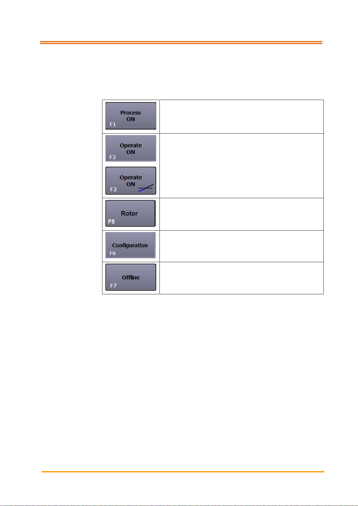
[F1] Process ON
[F2] Operate ON
or
[F2] Operate ON Trigger active
In this case, recording of measurement data only starts
after the trigger level has been exceeded
[F5] Rotor
[F6] Configuration
[F7] Offline
Pos: 66 /ARTIS/Seitenumbruch/-----Seitenumbruch---- @ 0\ mod_1384520666314_18.docx @ 3570 @ @ 1
Page 41

Basic settings
41
Pos: 67 /ARTIS/Beschreibung/4K_WISY/V ertikale Menüleiste @ 4\mod_1461 930777117_18.docx @ 190318 @ @ 1
Push key [F6] Configuration on page Visualization. Page Visualization settings
with a vertical menu bar on the right side is displayed.
[sF1] Rotor
Push Shift + [F1] and navigate to page Rotor settings,
see chapter Commissioning
[sF6] User level
Push Shift + [F6]. The authentication dialog is displayed
(for service purposes only)
[sF7] About
Push Shift + [F7]. Information about the Qt-class library
[sF8] Back
Push Shift + [F8] to step back
Pos: 68 /ARTIS/Seitenumbruch/-----Seitenumbruch---- @ 0\ mod_1384520666314_18.docx @ 3570 @ @ 1
Page 42

Basic settings
42
Pos: 69 /ARTIS/Überschriften/H2/V/ÜS _Visualisierung einstellen @ 4\mod_146 1927995005_18.docx @ 190097 @ 2 @ 1
7.1 Setting the visualization
Pos: 70 /ARTIS/Beschreibung/4K_WISY/Vis ualisierung einstellen @ 4\mod_14 62182766053_18.docx @ 190437 @ @ 1
The settings for the 4 freely configurable windows which display the measurement
data are carried out on page Visualization settings.
1. Right-click the desired window.
The page Visualization settings is displayed.
2. Use drop-down list to select the desired display parameters in field View.
Plot type
Off
No data displayed
XY-plot
2 signals in XY-plot
Timeline
1 - 2 signals in timeline
Trend
Trend of measurement data
1st – 4th signal
No signal
Signal not assigned
Torque
Select torque signal
Force
Select axial force signal
Bending 0°
Select bending 0° signal
Bending 90°
Select bending 90° signal
Bending value
Bending angle
Show legend
Set checkmark
Color assignment of the
different signals is displayed in
the plot
Ratio 1:1
Set checkmark
Activate square display option
(only available with XY-Plot)
Filter active
Set checkmark
Activate filter (only available
with Plot type = Timeline)
Filter
Mean
Moving average value based
on x points
Max
Maximum value
Min
Minimum value
Peak to Peak
Peak to Peak
Time
Enter value
(max. 99)
Time in seconds for mean filter
value
3. Push key [sF8] Back.
Pos: 71 /ARTIS/Überschriften/H2/W/ÜS_ Werkzeuglänge einstellen @ 4\mod_1 467294837514_18.docx @ 205424 @ 2 @ 1
Page 43

Basic settings
43
7.2 Setting the tool length
Pos: 72 /ARTIS/Beschreibung/4K_WISY/W erkzeuglänge einstellen @ 4\mod_14 67294798035_18.docx @ 205402 @ @ 1
Move back to the page Visualization settings in order to enter the tool length.
Abb. 12: Visualization setting
The system requires information about the tool length if the function Convert
bending to Newton is selected.
1. Set checkmark Convert bending to Newton.
2. Enter total throat depth in mm into the designated field.
Pos: 73 /ARTIS/Seitenumbruch/-----Seitenumbruch---- @ 0\ mod_1384520666314_18.docx @ 3570 @ @ 1
Page 44

Basic settings
44
Pos: 74 /ARTIS/Überschriften/H2/S/ÜS _Skalierung der Visualisierung festlegen @ 4\mod_1467295166097_18.docx @ 20 5447 @ 2 @ 1
7.3 Setting the scaling of the visualization
Pos: 75 /ARTIS/Beschreibung/4K_WISY/S kalierung der Visualisierung festlegen @ 4\mod_1467295248753_18.docx @ 2 05470 @ @ 1
Set checkmark Use fixed scaling, in order to deactivate the automatic auto scaling
function of the measurement data in the visualization.
Pos: 76 /ARTIS/Überschriften/H2/T/ÜS_Trig ger einstellen @ 5\mod_14758348 07958_18.docx @ 234553 @ 2 @ 1
7.4 Setting the trigger
Pos: 77 /ARTIS/Beschreibung/4K_WISY/T rigger einstellen @ 5\mod_147583498 2680_18.docx @ 234598 @ @ 1
With activated Trigger function, measuring starts once the trigger level is exceeded.
Active
Set checkmark
Activate trigger
Signal
No signal
Signal not assigned
Torque
Select torque signal
Axial force
Select axial force signal
Bending 0°
Select bending 0° signal
Bending 90°
Select bending 90° signal
Bending value
Select bending value signal
Bending angle
Select bending angle signal
Level
Enter value
Define height of trigger level
Filter mean time (sec)
Enter value
Automatic Trigger
Enter value
Define lead/lag and delay time
Trigger with duration
Enter value
Define lead time, delay,
duration and total length of
time
Pos: 78 /ARTIS/Seitenumbruch/-----Seitenumbruch---- @ 0\ mod_1384520666314_18.docx @ 3570 @ @ 1
Page 45

Basic settings
45
Pos: 79 /ARTIS/Überschriften/H2/R/ÜS_R eport_Prozesseinstellungen @ 5\m od_1476797987016_18.docx @ 236381 @ 2 @ 1
7.5 Selecting the storage location of the report and process settings
Pos: 80 /ARTIS/Beschreibung/4K_WISY/S peicherort der Report_Prozesseinstellu ngen auswählen @ 4\mod_1462190284 016_18.docx @ 190503 @ @ 1
All measurements are stored automatically to the directory, which was selected after
pushing Process ON (page Visualization). The path to the process settings leads
into the file system of the computer, which is used for running the 4K-WISY-Visu.
Open the file system and select a directory
Pos: 81 /ARTIS/Überschriften/H2/S/ÜS _Schnittstelle einstellen @ 4\mod_146 2191131554_18.docx @ 190569 @ 2 @ 1
7.6 Setting the interface
Pos: 82 /ARTIS/Beschreibung/4K_WISY/Sc hnittstelle einstellen @ 4\mod_14621 91225388_18.docx @ 190592 @ @ 1
The desired I/O parameters are defined on the page I/O settings.
Digital input
: External input active
: External input inactive
Low active
Radio button
Level for external input (0 V)
High active
Radio button
Level for external input (24V)
Pos: 83 /ARTIS/Seitenumbruch/-----Seitenumbruch---- @ 0\ mod_1384520666314_18.docx @ 3570 @ @ 1
Page 46

Basic settings
46
Pos: 84 /ARTIS/Überschriften/H2/R/ÜS_R otor-Einstellungen @ 4\mod_146219 1702369_18.docx @ 190636 @ 2 @ 1
7.7 Setting the rotor
Pos: 85 /ARTIS/Hinweise/Hinweis_Rotor-Ei nstellungen @ 4\mod_1462192397 652_18.docx @ 190703 @ @ 1
Information
More information about adding and removing rotors can be found in chapter
Commissioning.
Pos: 86 /ARTIS/Seitenumbruch/-----Seitenumbruch---- @ 0\ mod_1384520666314_18.docx @ 3570 @ @ 1
Page 47

Operation
47
Pos: 87 /ARTIS/Überschriften/H1/B/Ü S_Bedienung @ 0\mod_13831428218 04_18.docx @ 1983 @ 1 @ 1
8 Operation
Pos: 88 /ARTIS/Bedienung/Sensoren/ 4K-WISY/Prozess EIN @ 4\mod_14621 94053333_18.docx @ 190757 @ 2 @ 1
8.1 Process ON
All measurement data are saved and stored automatically into the directory, which
has been selected after pushing key [F1] Process ON (page Visualization).
1. Push key [F1] Process ON. The system automatically displays the
measurement directory, which was used last. If this measurement is to be
continued, confirm by pushing OK.
2. If another directory is to be used or if a new directory is to be created, proceed
as follows:
1. Push the icon Browse klicken .
The dialog Choose or create directory is displayed.
2. Select directory or enter a new directory name, push Select folder to
confirm.
3. Push OK to confirm.
Fig. 13: Process ON
Pos: 89 /ARTIS/Seitenumbruch/-----Seitenumbruch---- @ 0\ mod_1384520666314_18.docx @ 3570 @ @ 1
Page 48

Operation
48
Pos: 90 /ARTIS/Überschriften/H2/R/ÜS_R eport-Einstellungen @ 5\mod_14758 40484982_18.docx @ 234664 @ 2 @ 1
8.2 Report settings
Pos: 91 /ARTIS/Bedienung/Sensoren/ 4K-WISY/Report-Einstellungen @ 5\mo d_1475840562233_18.docx @ 234687 @ @ 1
The following screen is displayed if empty (newly created) measuring folders are
selected. All entry fields may be edited.
Process
Preconfigured:
The list of processes can be
adapted arbitrarily*. Process
parameters depend on the
selected process type.
Drilling
Threading
Reaming
Milling
User
Enter name
Product
Enter name
Process parameters
Enter value
Depending on process type
User sets
Select settings
Select pre-configured settings
Save
Save process
parameters
Name is adopted from the list
User sets.
Delete
Delete process
parameters
Selcted configuration is
deleted form the list User
sets.
* Adaptation of file 4K_WiSy_ProcessingSet.ini
Pos: 92 /ARTIS/Seitenumbruch/-----Seitenumbruch---- @ 0\ mod_1384520666314_18.docx @ 3570 @ @ 1
Page 49
Operation
49
Pos: 93 /ARTIS/Bedienung/Sensoren/ 4K-WISY/Bearbeitung EIN @ 4\mod_1462 274570242_18.docx @ 191293 @ 2 @ 1
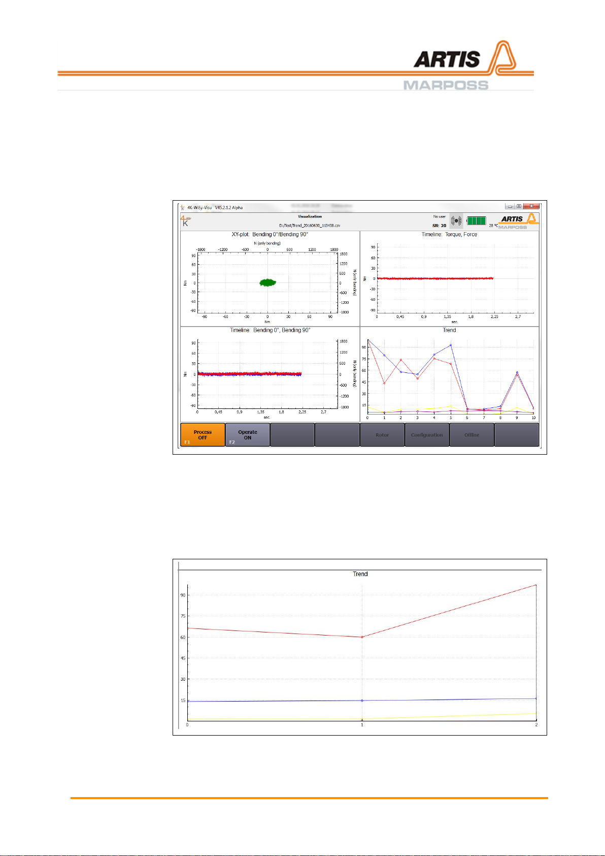
8.3 Operate ON
Key [F2] or the external output are assigned alternatively with either Operate ON
or Operate OFF. Measurement data are logged while the key [F2] is displayed in
orange color.
1. Push key [F2] Operate ON. Measurement data are logged. The color and the
labelling of the key [F2] switches to orange and Operate OFF.
Fig. 14: Operate ON
2. The measurement data are displayed in the windows, which have been
configured beforehand (see chapter Commissioning).
3. Shift key [F2] Operate OFF. Logging of measurement data is stopped. With
each ON/OFF, another cycle is added to the directory, which has been
selected after pushing Process ON.
4. A Trend curve is now displayed in the trend-window.
Fig. 15: Trend-window
Pos: 94 /ARTIS/Seitenumbruch/-----Seitenumbruch---- @ 0\ mod_1384520666314_18.docx @ 3570 @ @ 1
Page 50

Evaluating the measurement data
50
Pos: 95 /ARTIS/Überschriften/H1/M/ÜS_M essdaten evaluieren @ 4\mod_1462 277979573_18.docx @ 191360 @ 1 @ 1
9 Evaluating the measurement data
Pos: 96 /ARTIS/Bedienung/Sensoren/ 4K-WISY/Offline-Rekorderöffnen @ 4\ mod_1462278124841_18.docx @ 191405 @ @ 1
The collected measurement data can be retrieved from the Offline recorder.
Push key [F7] Offline in the horizontal menu bar for switching to the Offline recorder.
The page Offline recorder is displayed.
Fig. 16: Offline recorder
Information
This function is only available if process recording is switched to Process OFF.
Pos: 97 /ARTIS/Seitenumbruch/-----Seitenumbruch---- @ 0\ mod_1384520666314_18.docx @ 3570 @ @ 1
Page 51
Evaluating the measurement data
51
Pos: 98 /ARTIS/Bedienung/Sensoren/ 4K-WISY/Offline-Rekorder Menüleiste @ 4\ mod_1462278919171_18.docx @ 191 449 @ @ 1
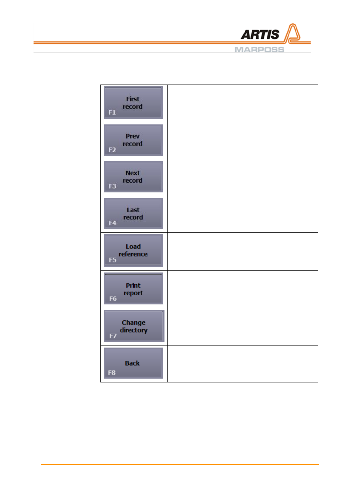
Menu bar
The menu bar is located in the lower part of the screen. Depending on the current
user level, the display of active [F]-keys may vary.
[F1] First record
Move to first recording
[F2] Prev record
Move to previous recording
[F3] Next record
Move to following record
[F4] Last record
Move to last recording
[F5] Load reference
Load reference recording. The loaded recording is
displayed in yellow and shows deviations between the
current and the reference recording
[F6] Print report
Print current cut
[F7] Change directory
Move to another recording directory
[F8] Back
Step back
Pos: 99 /ARTIS/Seitenumbruch/-----Seitenumbruch---- @ 0\ mod_1384520666314_18.docx @ 3570 @ @ 1
Page 52

Evaluating the measurement data
52
Pos: 100 /ARTIS/Bedienung/Sensoren/4 K-WISY/Offline-Modus Cursor-Optione n @ 4\mod_1462280477686_18.docx @ 191647 @ @ 1
Double-clicking the headline of a window opens this particular window in
full screen mode.
The tool bar for setting the display options is located beneath the recording
windows.
Slide control
The slide control is used for moving the cursor
area within the display.
Show cursor
: A certain part of the display is selected by a
cursor. The number of points in the spin box
determines the size of the cursor area.
: No part selected.
Synchronous
zooming
: all timeline views scroll synchronously
: only the selected timeline view scrolls
Ctrl-key + mouse wheel: Y-axis is zoomed
Alt-key + mouse wheel: X-axis is zoomed
Position cursor in
timeline view
Select any point of the curve by mouse clicking
and display time of measurement and
measurement values for the selected point.
Position cursor in
trend view
Select any point of the curve by mouse clicking
and display measurement values for the selected
point.
Page 53

Evaluating the measurement data
53
Context menu in the Trend view (right-click to display)
Show this
measurement
Click measurement
The selected measurement
is displayed in all windows
Set as reference
Click measurement
The selected measurement
is set as reference
measurement
Show in Explorer
Click measurement
Explorer is opened, the
selected measurement is
highlighted
Ignore measurement
/ Insert measurement
Click measurement
Measurement is either
ignored or displayed in the
Trend view
Visualization
settings
Select entry
Context menu Visualization
Settings is displayed
Pos: 101 /ARTIS/Seitenumbruch/-----Seitenumbruc h---- @ 0\mod_1384520666314_18.docx @ 3570 @ @ 1
Page 54

Creating a report
54
Pos: 102 /ARTIS/Überschriften/H1/R/ÜS _Report erstellen @ 5\mod_1479885 627592_18.docx @ 238997 @ 1 @ 1
10 Creating a report
Pos: 103 /ARTIS/Bedienung/Sensoren/4 K-WISY/Offline-Rekorderöffnen @ 4\mo d_1462278124841_18.docx @ 191405 @ @ 1
The collected measurement data can be retrieved from the Offline recorder.
Push key [F7] Offline in the horizontal menu bar for switching to the Offline recorder.
The page Offline recorder is displayed.
Fig. 17: Offline recorder
Information
This function is only available if process recording is switched to Process OFF.
Pos: 104 /ARTIS/Bedienung/Sensoren/4 K-WISY/Report erstellen @ 5\mod_14 79885858915_18.docx @ 239030 @ @ 1
In order to navigate to the report tool, push key [F6] Print report in the horizontal
menu bar.
The following screen with the report dialog is displayed.
Page 55

Creating a report
55
Entry field
(at the upper edge of the screen)
Enter report title
Report settings
These fields cannot be edited in
this dialog.
The data basis for the report is the
measurement directory which was
selected when recording the
measurements Process ON.
In order to create a report using
data from a different measurement
directory, carry out the following
steps:
• Push Cancel and end report
dialog
• Push key [F7] Change
directory
• Push key Select folder.
• Push key [F6] Print report
and return to the report
dialog.
Visualization
(here: trend curve)
One visualization window is already
opened.
The context menu (right-click to
display) is used for navigating in the
visualization window.
This context menu allows the
following actions:
• Show this measurement
• Set as reference
• Visualization settings
(see chapter Evaluating the
measurement data)
Page 56

Creating a report
56
Keys Plus-/Minus
Reports can be added to/removed
from the report using the keys Plus
and Minus.
Record number
Direct selection of certain
measurements for the report.
Visualization settings
Right-click in any of the
visualization windows in order to
open the menu Visualization
settings. This context menu allows
the following actions:
• Select plot type
• Select signal type
• Show legend
• Ratio 1:1
• Filter active
• Filter
• Time
(see chapter Setting the
visualization).
Notes
Field for additional information.
Page 57
Creating a report
57
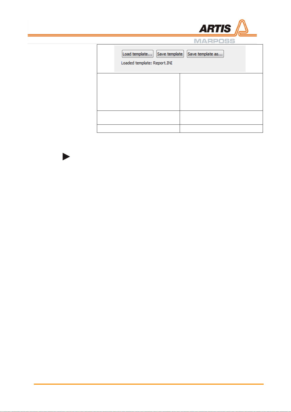
Load template
Save template
Save template as …
In this example, the report bases on
the template Report.INI.
Administration of report templates
is carried out with the keys Load
template/Save template/Save
template as.
Printing
Printing the report with all selected
viaualizations as PDF-file.
Cancel
End report dialog.
Information zur Anpassung des Report-Layouts
Im Verzeichnis 4K-Visu befindet sich ein Unterverzeichnis Report. In diesem
Unterverzeichnis sind zwei PNG-Dateien abgelegt:
• Logo-Left.png
• Logo-Right.png
Das Report-Layout lässt sich individualisieren, indem diese Datei(en) ausgetauscht
werden.
Pos: 105 /ARTIS/Seitenumbruch/-----Seitenumbruc h---- @ 0\mod_1384520666314_18.docx @ 3570 @ @ 1
Page 58

Maintenance
58
Pos: 106 /ARTIS/Überschriften/H1/W/ÜS _Wartung @ 0\mod_1383143161374_ 18.docx @ 2007 @ 1 @ 1
11 Maintenance
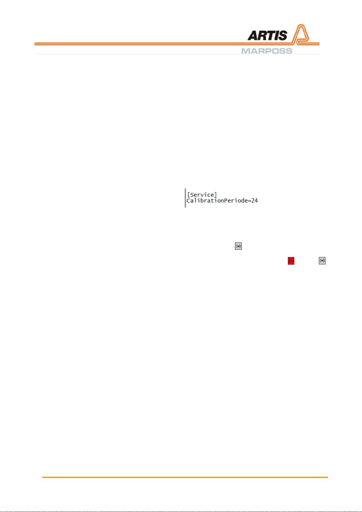
Pos: 107 /ARTIS/Wartung/Kalibrierinter vall @ 5\mod_1479822950381_18.docx @ 238969 @ @ 1
The rotor applies to the specifications stated in this document and is calibrated
ex works.
The recommended calibration interval is 24 months.
In order to adhere to the recommended calibration interval, the field Calibration date
on the page Rotor settings is highlighted in yellow after the period of 24 months
has elapsed.
The configuration of the calibration interval is carried out in the file 4K_WiSy_Visu:
24 = 24 months.
Pos: 108 /ARTIS/Seitenumbruch/-----Seitenumbruc h---- @ 0\mod_1384520666314_18.docx @ 3570 @ @ 1
Page 59

Appendix
59
Pos: 109 /ARTIS/Überschriften/H1/A/ÜS_ Anhang @ 0\mod_1383128782297_18. docx @ 1873 @ 1 @ 1
12 Appendix
Pos: 110 /ARTIS/Überschriften/H2/K/ÜS_ Konformitätserklärungen @ 5\mod_ 1481117944660_18.docx @ 240727 @ 2 @ 1
12.1 Declaration of conformity
Pos: 111 /ARTIS/Konformitätserklärung en/FCC @ 5\mod_1481114441033_0.d ocx @ 240657 @ 33 @ 1
12.1.1 FCC Konformitätserklärung
Federal Communication Commission Interference Statement
This equipment has been tested and found to comply with the limits for a Class B
digital device, pursuant to Part 15 of the FCC Rules. These limits are designed to
provide reasonable protection against harmful interference in a residential
installation.
This equipment generates uses and can radiate radio frequency energy and, if not
installed and used in accordance with the instructions, may cause harmful
interference to radio communications.
However, there is no guarantee that interference will not occur in a particular
installation. If this equipment does cause harmful interference to radio or television
reception, which can be determined by turning the equipment off and on, the user is
encouraged to try to correct the interference by one of the following measures:
– Reorient or relocate the receiving antenna.
– Increase the separation between the equipment and receiver.
– Connect the equipment into an outlet on a circuit different from that to which
the receiver is connected.
– Consult the dealer or an experienced radio/TV technician for help.
This device complies with Part 15 of the FCC Rules. Operation is subject to the
following two conditions: (1) This device may not cause harmful interference, and (2)
this device must accept any interference received, including interference that may
cause undesired operation.
Any changes or modifications not expressly approved by the party
responsible for compliance could void the user's authority to operate this
equipment.
Conformité aux normes FCC Cet équipement a été testé et trouvé conforme aux
limites pour un dispositif numérique de classe B, conformément à la Partie 15 des
règlements de la FCC. Ces limites sont conçues pour fournir une protection
raisonnable contre les interférences nuisibles dans une installation résidentielle.
Cet équipement génère, utilise et peut émettre des fréquences radio et, s’il n’est pas
installé et utilisé conformément ment aux instructions du fabricant, peut causer des
interferences nuisibles aux communications radio.
Rien ne garantit cependant que l’interférence ne se produira pas dans une
installation particulière. Si cet équipement provoque des interférences nuisibles à la
réception radio ou de télévision, qui peut être déterminé en comparant et en
l’éteignant, l’utilisateur est encouragé à essayer de corriger les interférence par une
ou plusieurs des mesures suivantes:
– Réorienter ou déplacer l’antenne de réception.
– Augmenter la distance entre l’équipement et le récepteur.
– Branchez l’appareil dans une prise sur un circuit différent de celui auquel le
récepteur est connecté.
– Consultez votre revendeur ou un technicien radio/ TV pour assistance.
Les changements ou modififications à cet appareil sans expressément
approuvée par la partie responsable de conformité pourraient annuler
l’autorité de l’utilisateur de faire fonctionner cet équipement.
Pos: 112 /ARTIS/Seitenumbruch/-----Seitenumbruc h---- @ 0\mod_1384520666314_18.docx @ 3570 @ @ 1
Page 60

Appendix
60
Pos: 113 /ARTIS/Konformitätserklärung en/ISED @ 5\mod_1481114500340_0.d ocx @ 240679 @ 33 @ 1
12.1.2 Konformitätserklärung für Kanada
Industry Canada Statements
This device complies with Industry Canada license-exempt RSS standard(s).
Operation is subject to the following two conditions: (1) this device may not cause
interference, and (2) this device must accept any interference, including interference
that may cause undesired operation of the device.
This device complies with RSS-210 of the Industry Canada Rules. Operation is
subject to the following two conditions: (1) this device may not cause interference,
and (2) this device must accept any interference, including interference that may
cause undesired operation of the device.
To reduce potential radio interference to other users, the antenna type and its gain
should be so chosen that the equivalent isotropically radiated power (e.i.r.p.) is not
more than that permitted for successful communication.
This device has been designed to operate with the antennas listed in the filing, and
having a maximum gain of 3 dBi. Antennas not included in this list or having a gain
greater than 3 dBi are strictly prohibited for use with this device. The required
antenna impedance is 50 ohms.
Cet appareil est conforme avec Industrie Canada exempt de licence Rss
standard(s). Son fonctionnement est soumis aux deux conditions suivantes: (1) cet
appareil ne peut causer d’interférences, et (2) cet appareil doit accepter toute
interférence, y compris des interférences qui peuvent provoquer un fonctionnement
indésirable du périphérique.
Cet appareil est conforme à la norme CNR-210 d’Industrie Canada applicable aux
appareils radio exempts de licence. Son fonctionnement est sujet aux deux
conditions suivantes: (1) le dispositif ne doit pas produire de brouillage préjudiciable,
et (2) ce dispositif doit accepter tout brouillage reçu, y compris un brouillage
susceptible de provoquer un fonctionnement indésirable.
Pour réduire le risque d’interférence aux autres utilisateurs, le type d’antenne et son
gain doivent être choisies de façon que la puissance isotrope rayonnée équivalente
(e.i.r.p) ne dépasse pas celle admise pour une communication réussie.
Cet appareil a été conçu pour fonctionner avec les antennes énumérées ci-dessous,
et ayant un gain maximum de 3 dB. Antennes pas inclus dans cette liste ou ayant
un gain supérieur à 3 dB sont strictement interdites pour une utilisation avec cet
appareil. L’impédance d’antenne requise est de 50 ohms.
Pos: 114 /ARTIS/Seitenumbruch/-----Seitenumbruc h---- @ 0\mod_1384520666314_18.docx @ 3570 @ @ 1
Page 61

Index
61
=== Ende der Liste für Textmarke Inhalt ===
13 Index
A
Abbreviations ............................................................... 7
Ambient conditions ................................................. 9, 14
Appendix .................................................................... 59
B
Basic settings ............................................................. 36
C
Chemicals .................................................................... 8
Commissioning ........................................................... 33
Conditions, on site ...................................................... 14
Contact details ............................................................. 5
Customer service ......................................................... 5
D
Declaration of conformity............................................ 59
Description ................................................................. 15
Disturbances .............................................................. 12
E
Electrical safety .......................................................... 14
G
General ........................................................................ 5
I
Installation .................................................................. 20
Intended use .............................................................. 11
Interface, settings ....................................................... 45
Interference ................................................................ 10
L
Liability ................................................................. 10, 13
M
Maintenance ............................................................... 58
Measurement data, evaluation ................................... 50
Misuse, warning ......................................................... 11
O
Operation .................................................................... 47
P
Packaging ..................................................................... 9
Process settings, storage location .............................. 45
R
Recycling ...................................................................... 8
Repair ......................................................................... 13
Report ......................................................................... 54
Report settings, storage location ................................ 45
Report, settings .......................................................... 48
Risk of injury ................................................................. 6
RoHS ............................................................................ 8
Rotor settings ............................................................. 46
S
Safety ........................................................................... 6
Scaling, setting ........................................................... 44
Storage ......................................................................... 9
T
Technical customer service .......................................... 5
Technical data ............................................................ 16
Tool length, setting ..................................................... 43
Transport ...................................................................... 9
Trigger, setting ........................................................... 44
U
User groups, requirements ......................................... 14
V
Visualization, setting ................................................... 42
W
Warranty ..................................................................... 10
Warranty exemption ................................................... 13
WEEE ........................................................................... 8
 Loading...