

Page 1
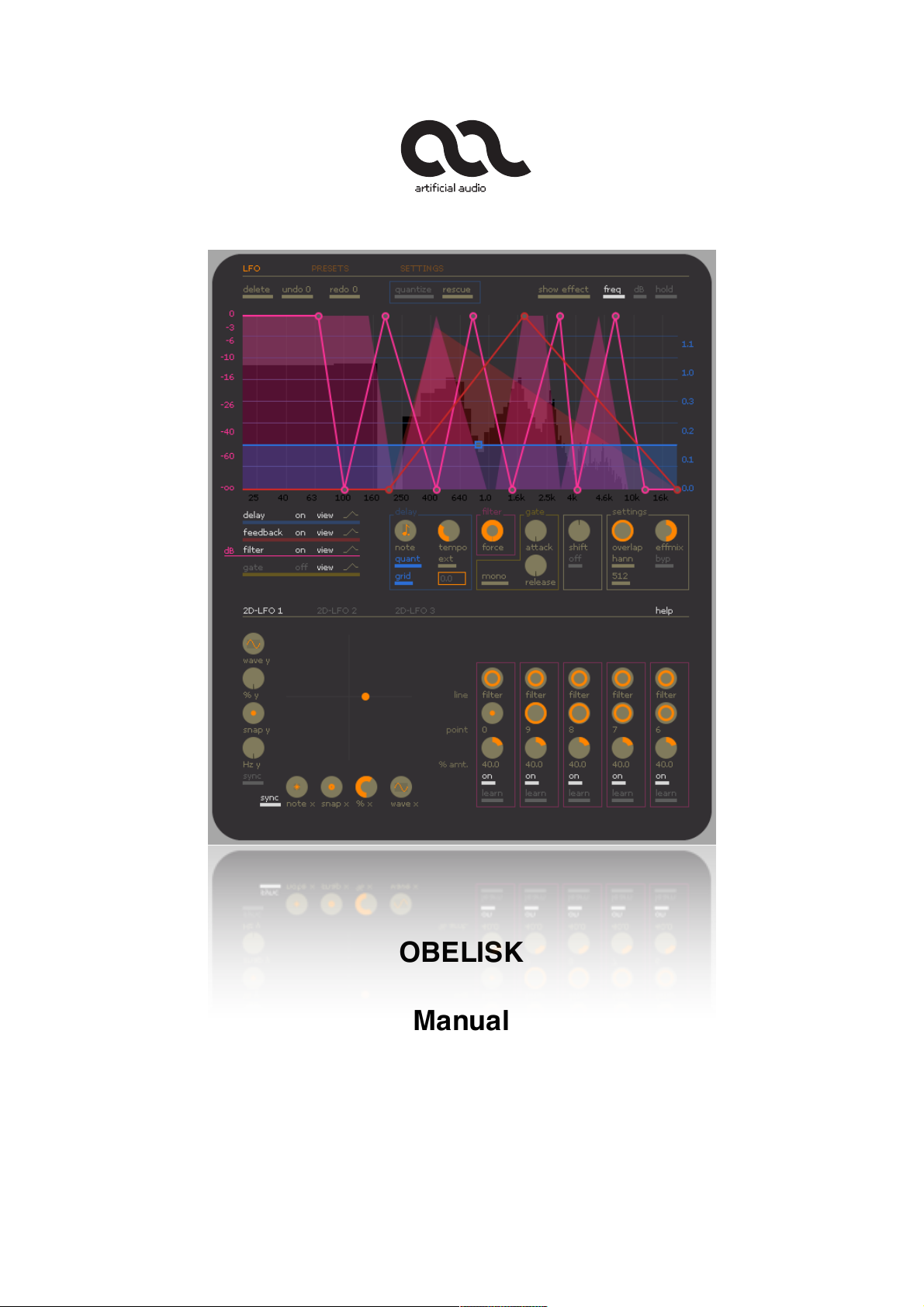
OBELISK
Manual
Version 1.1
Page 2

artificial audio ! OBELISK manual
TABLE OF CONTENT
...............................................................................................................................Installation! 3
...........................................................................................................................Authorization! 5
.............................................................................................................................Introduction! 6
...............................................................................................................................Quick start! 6
.................................................................................................................The Preset Browser! 7
.......................................................................................................Basic operational concept! 8
........................................................................................................Working with effect lines! 11
.....................................................................................Operation with mouse and keyboard! 13
.........................................................................................................The Analyser Point View! 14
........................................................................................................................Effect selector! 15
................................................................................................................................Delay line! 16
.....................................................................................................................Delay parameter! 18
.........................................................................................................................Feedback line! 19
.................................................................................................................................Filter line! 20
.................................................................................................................................Gate line! 21
..........................................................................................................................Spectral shift! 23
..................................................................................................................................Settings! 24
.............................................................................................................................Modulation! 25
...............................................................................................................2 - Dimensional LFO! 25
.......................................................................................................Modulation of line points! 28
.................................................................................................................Modulation targets! 29
..........................................................................................................Miscellaneous remarks! 31
OBELISK was developed by Bernd Burhoff, 2008 - 2014.
artificial audio
bernd burhoff
flandernstr. 75
47147 münster / germany
bernd@artificialaudio.com
www.artificialaudio.com
artificial audio ® is a registered trade mark.
- page 2 -
Page 3
artificial audio ! OBELISK manual
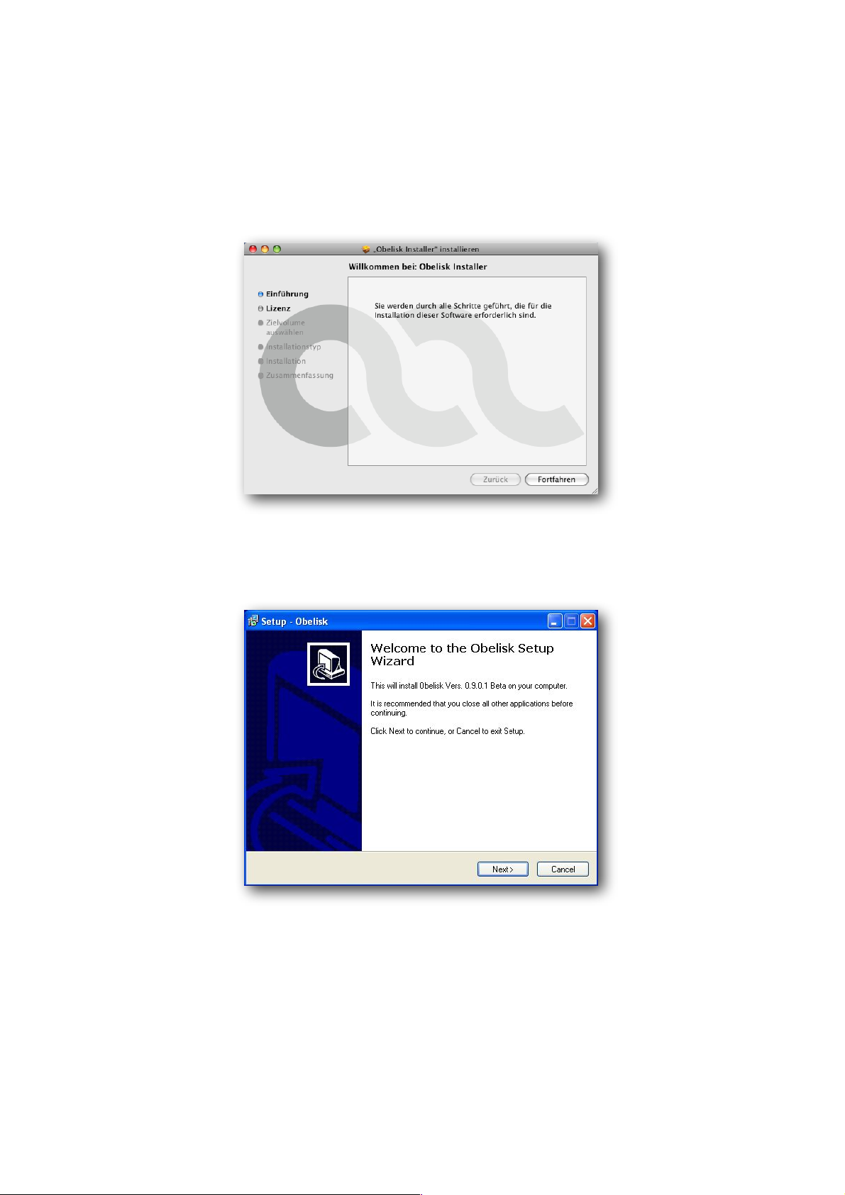
INSTALLATION
Start the OBELISK installer and follow the on-screen instructions.
On Mac :
On Windows:
- page 3 -
Page 4
artificial audio ! OBELISK manual
WHAT IS INSTALLED ?
On the Mac:
The OBELISK Audio Unit Plug-In is installed in:
/Library/Audio/Plug-Ins/Components
The OBELISK VST Plug-In is installed in:
/Library/Audio/Plug-Ins/VST
The OBELISK presets are installed in:
/Library/Audio/Presets/Artificial Audio/Obelisk/v1.1
On Windows:
By default all files are installed in:
C:\Program Files\Artificial Audio\Obelisk
You have to copy the OBELISK VST Plug-In to your desired VST folder. The respective VST folder
depends on the host application you use. Alternatively, you can add the OBELISK installation
folder to the VST Plug-In paths of your host application.
(In Cubase e.g. use : „Devices->Plug-In Information->VST 2.x Plug-in Paths“)
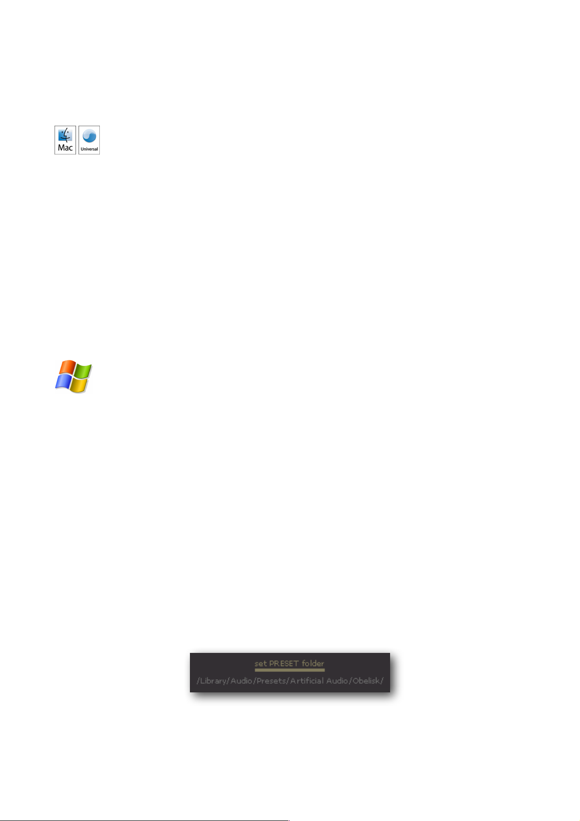
OBELISK utilizes an own data format for its presets. The preset data can be found in a special
folder. For Windows computers after installation you have to set the path to this folder in the
OBELISK - settings (Mac computers already have the path set after installation). For this click on
set PRESET folder and choose the directory in which the preset data is stored on your system:
- page 4 -
Page 5
artificial audio ! OBELISK manual
AUTHORIZATION
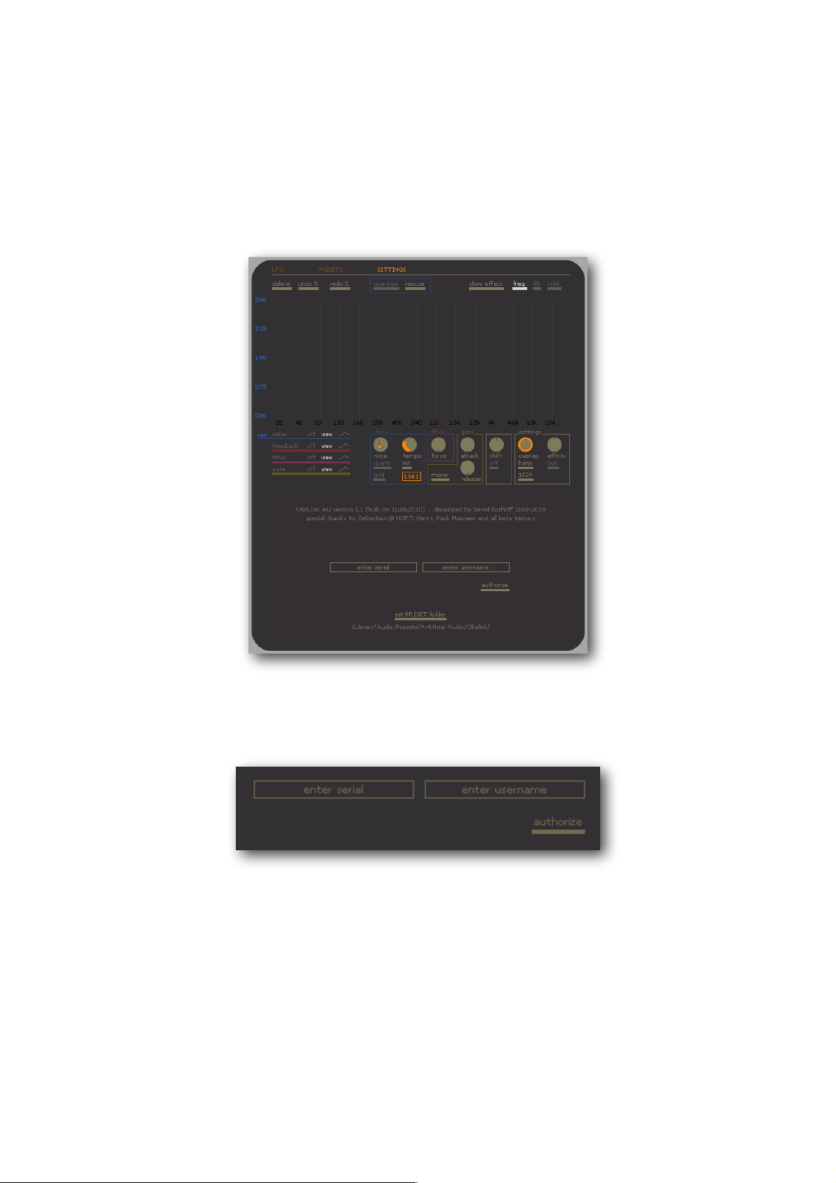
After installation you have to authorize OBELISK. To authorize OBELISK, your computer has to be
connected to the internet. Please open OBELISK in your host application and select „SETTINGS“
in the top left-hand corner. The following window will appear:
After purchasing OBELISK you receive a serial number in your confirmation mail. This number has
got two times five digits separated with a hyphen: 12345-12345.
Please enter this number in the „enter serial“ field. In the second field input your name or a name
of someone you want to authorize for the Plug-In. This name will later be displayed in the Plug-In
window.
With the button „authorize“ you start the authorisation procedure. After a few moments your Plug-
In is authorised and „ready to use“. If you receive an error message, please check that your
computer is connected to the internet and that you have input the serial number correctly. Then
restart the authorisation by pressing the button „authorize“.
- page 5 -
Page 6

artificial audio ! OBELISK manual
INTRODUCTION
OBELISK is a spectral multi effect whose sound possibilities and graphic user interface raise the
area of spectral sound processing to a completely new level. OBELISK combines a SPECTRAL
DELAY, a SPECTRAL FILTER and a SPECTRAL GATE to a multi effect that not only sounds
excellent but also enables an extremely intuitive and musical operation, making use of hundreds
of effect parameters. With OBELISK you can draw your effect and with the aid of graphic lines
control a multitude of effect parameters in a very simple and descriptive manner. With its 2-
dimensional LFOs, OBELISK creates completely innovative modulation possibilities by means of
which the processed signal transforms into an endlessly changing sound layer. In spite of the
comprehensive possibilities it provides for sound processing and modulation, OBELISK requires
very little computing power, thanks to its highly optimized vector algorithms.
OBELISK has a highly efficient spectral analysis and synthesis that ensures an excellent audio
quality. The audio signal can be split into 256 or 512 individual frequency bands that can be
independently processed with effects. Each frequency band has its own DELAY with FEEDBACK,
its own volume regulator (FILTER) and its own noise gate (GATE) with threshold.
QUICK START
If you want to start using OBELISK immediately, simply activate the help function which displays
useful information regarding the respective parameter shown by the mouse pointer.
However, before you start you should familiarize yourself with the basic operational concept in
particular with the EFFECT LINES. To do so either watch the „OBELISK VIDEO TOUR“ on the
artificial audio website ( www.artificialaudio.com/pluginmenu/obelisk ), or read the next section
„Basic Operational Concept“.
- page 6 -
Page 7
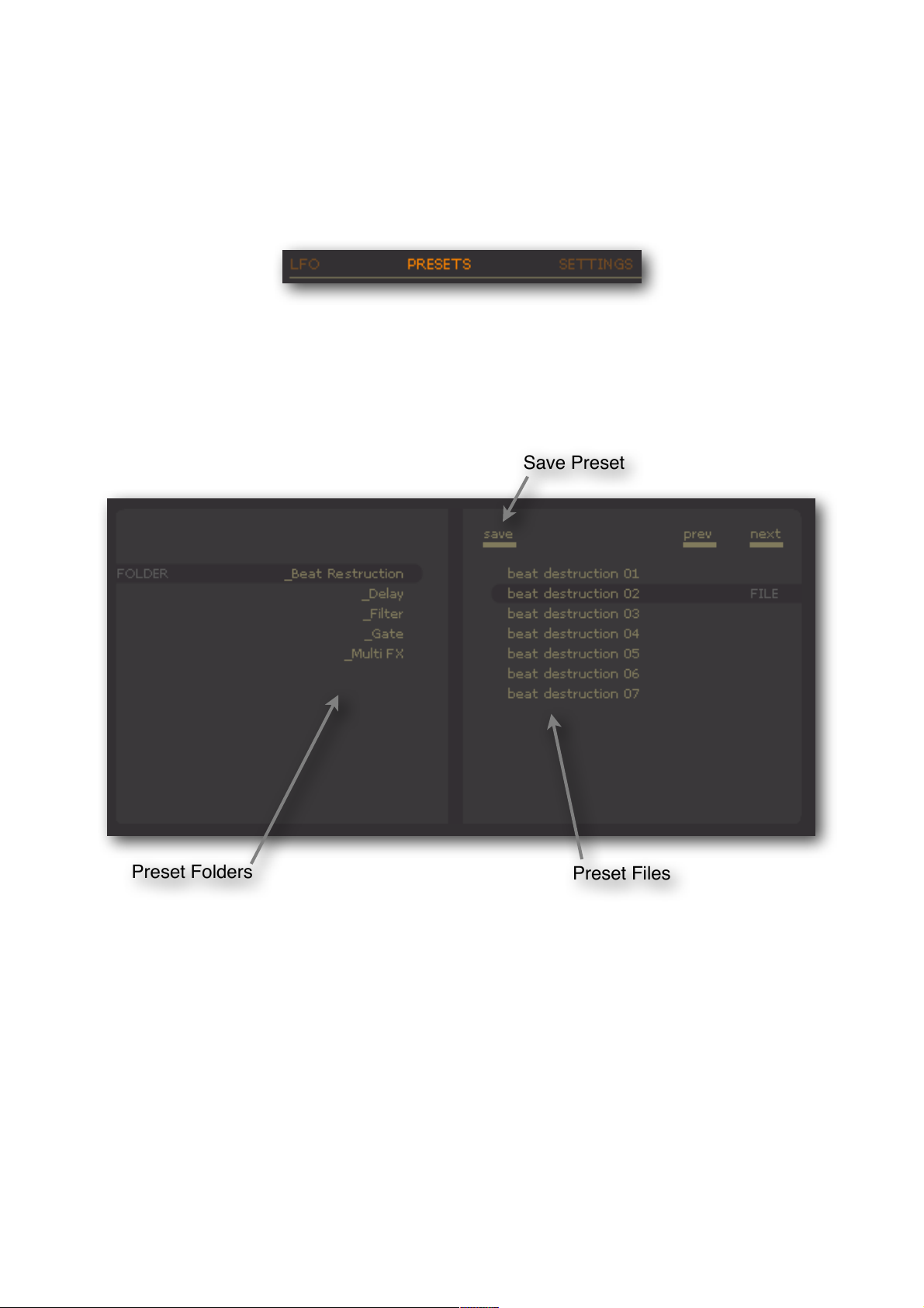
Preset Files
Preset Folders
Save Preset
artificial audio ! OBELISK manual
THE PRESET BROWSER
To be able to start with OBELISK immediately, it is best to make a short tour through the preset
library. To do so you have to activate the preset browser on the top left-hand of the screen:
The preset browser now appears in the bottom part of the window. On the left-hand side of the
browser you will see the preset folders. Click on a folder and you will see the preset files on the
right hand side of the browser that are contained in the chosen folder. A click on the preset file
loads the preset.
save" " to save a preset, activate the preset browser, and select the preset folder in which
" " you want to save your preset and click save
prev" " load the previous preset
next" " load the next preset
- page 7 -
Page 8
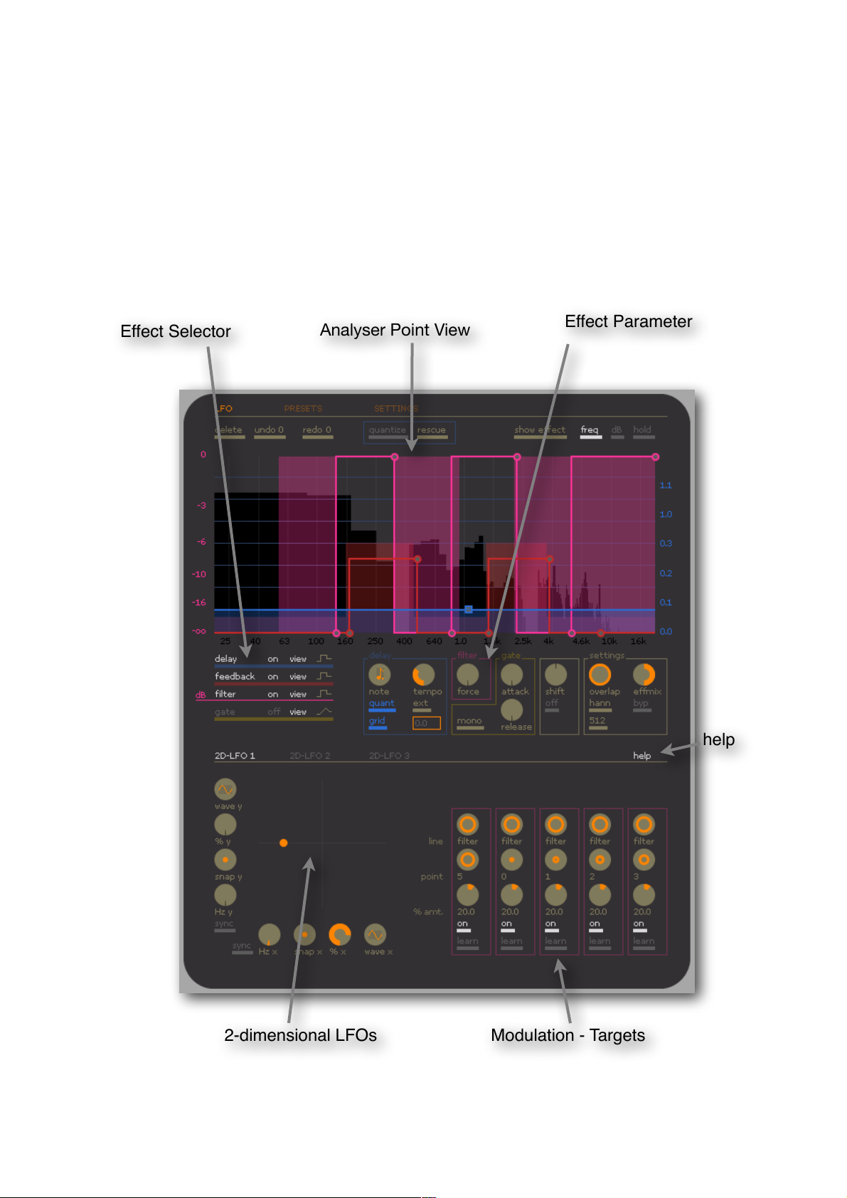
Analyser Point View
2-dimensional LFOs
Modulation - Targets
help
Effect Parameter
Effect Selector
artificial audio ! OBELISK manual
BASIC OPERATIONAL CONCEPT
The OBELISK window is divided into three areas: At the top there is the ANALYSER POINT VIEW
with the real-time spectrum analyser and the EFFECT LINES. In the middle there is the EFFECT
SELECTOR and the global effect parameters. At the bottom there is the modulation-area with the
2-dimensional LFOs.
- page 8 -
Page 9

artificial audio ! OBELISK manual
ANALYSER POINT VIEW
The ANALYSER POINT VIEW shows a real-time spectrum of the audio signal. The spectrum
consists of individual frequency bands and the low pitch frequencies are clearly indicated as
squares:
One or several effects can individually be assigned to each of these frequency bands: DELAY &
FEEDBACK, FILTER and GATE. The effect parameters can be drawn in the form of lines, the so-
called EFFECT LINES, via the analyser spectrum. Each EFFECT has got its own EFFECT LINE,
which is coloured: DELAY (blue), FEEDBACK (red), FILTER (magenta) and GATE (yellow).
The EFFECT LINES are made up of points, the so-called LINE POINTS. A LINE POINT determines
two values: its position on the horizontal (x-axis) determines the frequency or the frequency band
and its position on the vertical (y-axis) determines the parameter value whereby the higher the
LINE POINT, the greater the parameter value. The course of the EFFECT LINE and the area
underneath, the so-called EFFECT PLANE determines the parameter values for the individual
frequency bands.
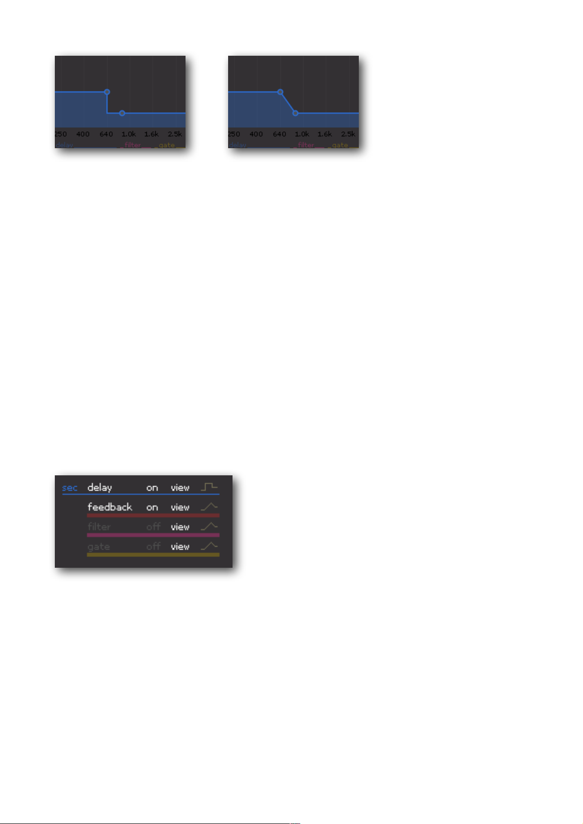
Each EFFECT LINE has got a certain LINE STYLE that determines how the points are linked
together to form a line. The polygon LINE STYLE connects two neighbouring points with a straight
line. The square LINE STYLE connects two neighbouring points with a rectangle cut-out.
- page 9 -
Page 10
artificial audio ! OBELISK manual
!
square"" " " " polygon
EFFECT SELECTOR
The EFFECT SELECTOR is the central control when working with EFFECT LINES. Here you chose
the desired EFFECT LINE before inserting new points into the ANALYSER POINT VIEW. You can
activate or deactivate the EFFECT and view of the EFFECT LINE independent from each other.
For each EFFECT LINE you can determine the respective LINE STYLE.
A click on delay, feedback, filter or gate activates the respective type of line and the related unit
will be displayed on the left hand side next to the ANALYSER POINT VIEW (e.g. seconds for
Delay):
EFFECT SELECTOR (with selected delay effect)
- page 10 -
Page 11
artificial audio ! OBELISK manual
WORKING WITH EFFECT LINES
In OBELISK the effect parameters (e.g. the delay times of the delay) are not adjusted with a
control dial or by inputs but rather are the result of the course of the EFFECT LINE. The parameter
value for a single frequency band results from the height of the EFFECT LINE above the
respective frequency band.
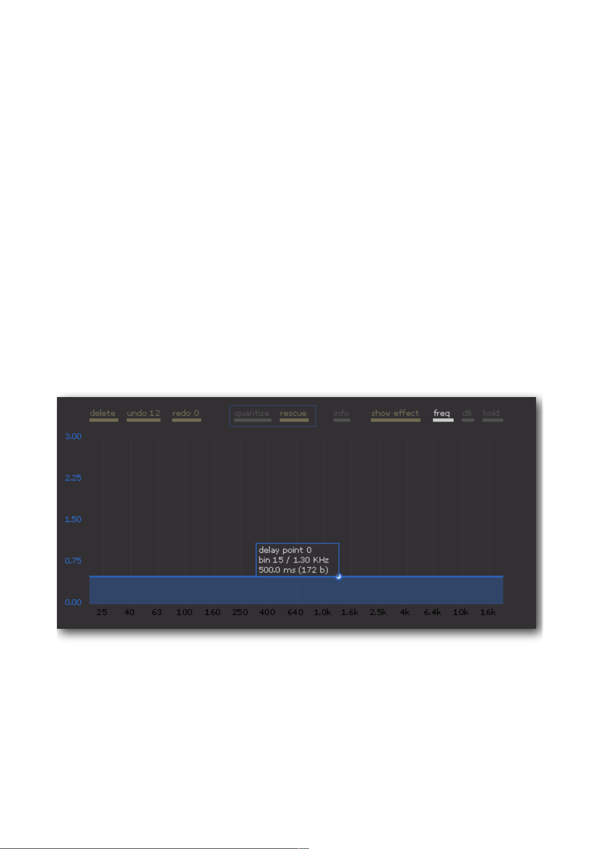
The following example illustrates this concept:
We want to determine a delay time of 500 ms for all the frequency bands. To do so we chose the
point type delay with the EFFECT SELECTOR. With command-click we now insert a new DELAY
POINT in the ANALYSER POINT VIEW. A new DELAY POINT and the DELAY LINE with the
underlying DELAY PLANE appear. We can move the point with the mouse which displays the
INFO BOX.
We position the point in the vertical (y-axis) to the position 500.0 ms.
A delay time of 500.0 ms is now set for all the frequency bands.
But we would now like to allocate another delay time to a certain frequency band. All frequency
below 640 Hz should be delayed by 1035 ms. We therefore insert a new delay point at the
position (640.0 Hz / 1035 ms).
- page 11 -
Page 12

artificial audio ! OBELISK manual
A delay time of 1035 ms is now set for all frequency bands up to 640 Hz. All frequency bands
above this value are delayed like before by 500 ms.
In this manner up to 10 DELAY POINTS can be inserted. As a result, up to 10 frequency bands
with various delay times can be determined.
With the EFFECT SELECTOR, you can set the LINE STYLE for every EFFECT LINE: square or
polygon. For the LINE STYLE square the connecting lines between two points are rectangular cut-
outs. For the LINE STYLE polygon the connecting lines are straight lines.
!
square"" " " " polygon
This basic operational concept is valid for all lines i.e. DELAY, FEEDBACK, FILTER und GATE.
- page 12 -
Page 13

artificial audio ! OBELISK manual
OPERATION WITH MOUSE AND KEYBOARD
Inserting a point " " " " " Command - Click
Deleting a point" " " " " Command & Shift - Click
Selecting individual points" " " " Click
Selecting additional points" " " " Shift - Click
Selecting several points simultaneously" " make a frame around them
Set the default value of a controller" " " Alt - Click on the respective controller
Fine adjustment of the controllers or points"" Shift - Click
Inserting a point " " " " " Ctrl - Click
Deleting a point" " " " " Ctrl & Shift - Click
Selecting individual points" " " " Click
Selecting additional points" " " " Shift - Click
Selecting several points simultaneously" " make a frame around them
Set the default value of a controller" " " Alt - Click on the respective controller
Fine adjustment of the controllers or points"" Shift - Click
- page 13 -
Page 14

artificial audio ! OBELISK manual
THE ANALYSER POINT VIEW
The ANALYSER POINT VIEW shows the real-time spectrum of the audio signal together with the
EFFECT LINES.
DELETE" " deletes all selected points (selected points are filled in white).
UNDO / REDO" cancels the following actions (up to 50 steps):
" " " Insert points, move points, delete points, quantize points.
QUANTIZE" " activates/deactivates the quantizing of selected delay points (quantized
" " " delay points are square).
RESCUE" " deletes the delay buffer (is useful for example with strong feedbacks)
INFO" " " shows information about OBELISK.
SOURCE" " selects the signal shown in the analyser:
"" "show input " shows the input signal
"" "show effect" shows the pure effect signal
"" "show output " shows the output signal (= input + effect)
FREQ" " " turns the vertical frequency guides on/off.
dB " " " turns the horizontal db guides on/off.
HOLD" " " turns the maximum-hold line on/off.
- page 14 -
Page 15
SELECTED EFFECT
EFFECT ON / OFF
LINE VIEW ON / OFF
LINE STYLE
artificial audio ! OBELISK manual
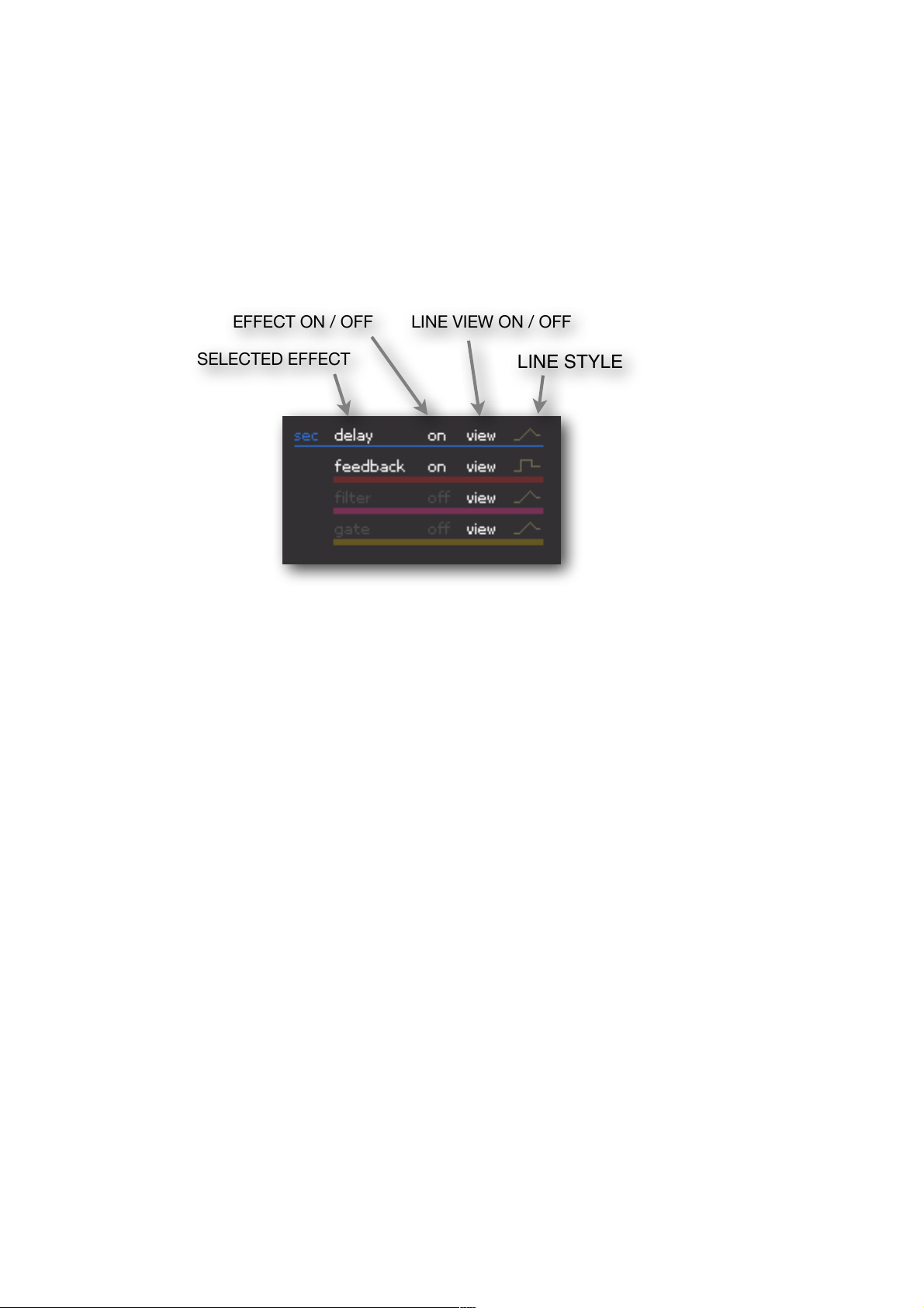
EFFECT SELECTOR
The EFFECT SELECTOR is the central switching element when working with EFFECT LINES. The
various effects are turned on and off here, the lines are made visible or invisible and the LINE
STYLE is adjusted for every type of line.
!!
SELECTED EFFECT " Before inserting new LINE POINTS you can chose the desired
EFFECT LINE here. A click on delay, feedback, filter or gate selects
the respective EFFECT LINE. The corresponding unit is displayed on
the left side of the EFFECT SELECTOR and on the left side next to
the ANALYSER POINT VIEW (e.g. sec. for DELAY).
EFFECT ON / OFF " Here the individual EFFECTS can be switched on or off (irrespective
of the EFFECT LINES being displayed).
LINE VIEW" The display of the EFFECT LINES can be switched on or off. EFFECT
LINES with switched off VIEW are visible in the background as grey
lines. Important: the LINE VIEW has no influence on the EFFECT
itself, but only on the depiction of the EFFECT LINE !
LINE STYLE" switches the LINE STYLE between polygon and square.
- page 15 -
Page 16
artificial audio ! OBELISK manual
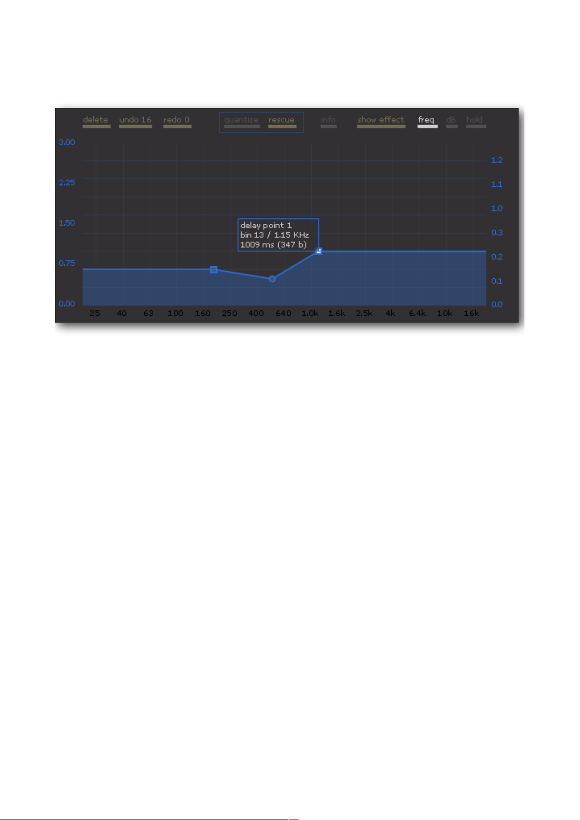
DELAY LINE
The DELAY LINE determines the delay time at a range of 0 sec to 3 sec for the individual
frequency bands. The POINT INFO BOX shows the point number for a DELAY POINT, the bin-
number (number of the frequency band) as well as the frequency in Hz and the delay time. The
delay time is depicted both in ms, as well as in analysis – blocks.
The display of the analysis-blocks has the following significance: when the input signal is
converted into the spectral display, the signal is divided into small blocks. The length of these
blocks is determined by the FRAME SIZE (512 or 1024). These blocks overlap each other in a
certain manner that is determined by the parameter OVERLAP (0%, 50%, 66%, and 75%). The
parameters FRAME SIZE and OVERLAP jointly determine the smallest possible interval for the
delay time. The possible delay times are thus „quantized“. The finest fragmentation ensues in
FRAME SIZE = 512 and OVERLAP = 75%. The finest fragmentation ensues in FRAME SIZE = 512
and OVERLAP = 75%. The length of a block is in this case equivalent to 2.9 ms (with a sampling
rate of 41.1 KHz). This is the smallest possible interval for the delay time.
As opposed to the other lines, the DELAY LINE has one distinctive feature: delay points can be
quantized and thus it is possible to additionally indicate delay times in beats as well as in
seconds. As a result the delay can be synchronized to the song tempo or to the Plug-In tempo. A
delay point becomes quantized when you select the point (it turns white) and then click on
quantize above the ANALYSER POINT VIEW. A quantized delay point is displayed as a square.
- page 16 -
Page 17

artificial audio ! OBELISK manual
!! !! !
unquantized"" " point quantized"" " point quantized
global quantize off"" " global quantize on
Independent of whether an individual delay point is quantized or not, the quantization of all points
can be globally activated or deactivated. The global quantization brings about that each
quantized delay point is drawn from its original position on to a grid that corresponds to the
adjusted beat values. Values for quantization are adjusted in the DELAY PARAMETERS.
- page 17 -
Page 18
artificial audio ! OBELISK manual
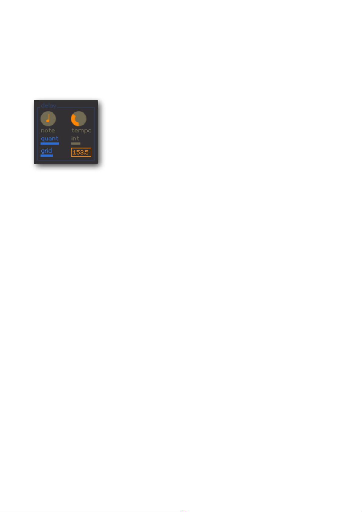
DELAY PARAMETER
In addition to the DELAY LINE there are global delay - parameters that are valid in equal measure
for all the frequency bands.
note " sets the note value for the quantization. All quantized delay points will be quantized
according to the note value that has been set here.
quant" activates the global quantization.
grid" activates the view of the quantization grid in the ANALYSER POINT VIEW.
tempo"" sets the internal tempo.
int. / ext." selects the tempo source: int. for internal tempo, ext for external host tempo. The
" " tempo chosen here is the basis for the quantization of delay points and for the
" " synchronisation of the LFOs.
Tempo field" the external tempo is displayed here (host - tempo).
The delay time of a delay point will only be quantized if the respective point is marked as a
quantized point (the point is square) and the global quantization is activated. A quantized point
remembers its original position to which it jumps back to when the quantization is switched off. If
the tempo changes when the global quantization is activated, the grid is automatically adjusted
and the delay points are drawn to the new grid position accordingly. Each quantized point will
always be drawn to the grid line that is nearest to its original (unquantized) position.
The quantize-grid can be activated with the grid switch. Blue horizontal grid lines appear as well
as a scale on the right hand side next to the ANALYSER POINT VIEW. The scale displays the
delay time in „Bar . Beat“: „0.2“ means: 2 beats, „1.3“ means: one bar and 2 beats.
- page 18 -
Page 19

artificial audio ! OBELISK manual
FEEDBACK LINE
The FEEDBACK LINE determines the feedback value for each frequency band. The feedback
values range between 0 % (at the bottom = feedback off) and 100 % (at the top = total feedback).
The feedback value determines the proportion of the delayed signal that is sent back to the
entrance of the delay. In order to hear a delay with feedback, both DELAY and FEEDBACK have
to be activated in the EFFECT SELECTOR and at least one delay point > 0 sec has to exist. The
POINT INFO BOX shows the point number, the bin number (number of the frequency band) as
well as the frequency in Hz and the feedback value in %.
RESCUE – Above the ANALYSER POINT VIEW the rescue – switch is located. A click on rescue
deletes the delay buffer. This can be very useful when working with high feedback values.
- page 19 -
Page 20
artificial audio ! OBELISK manual
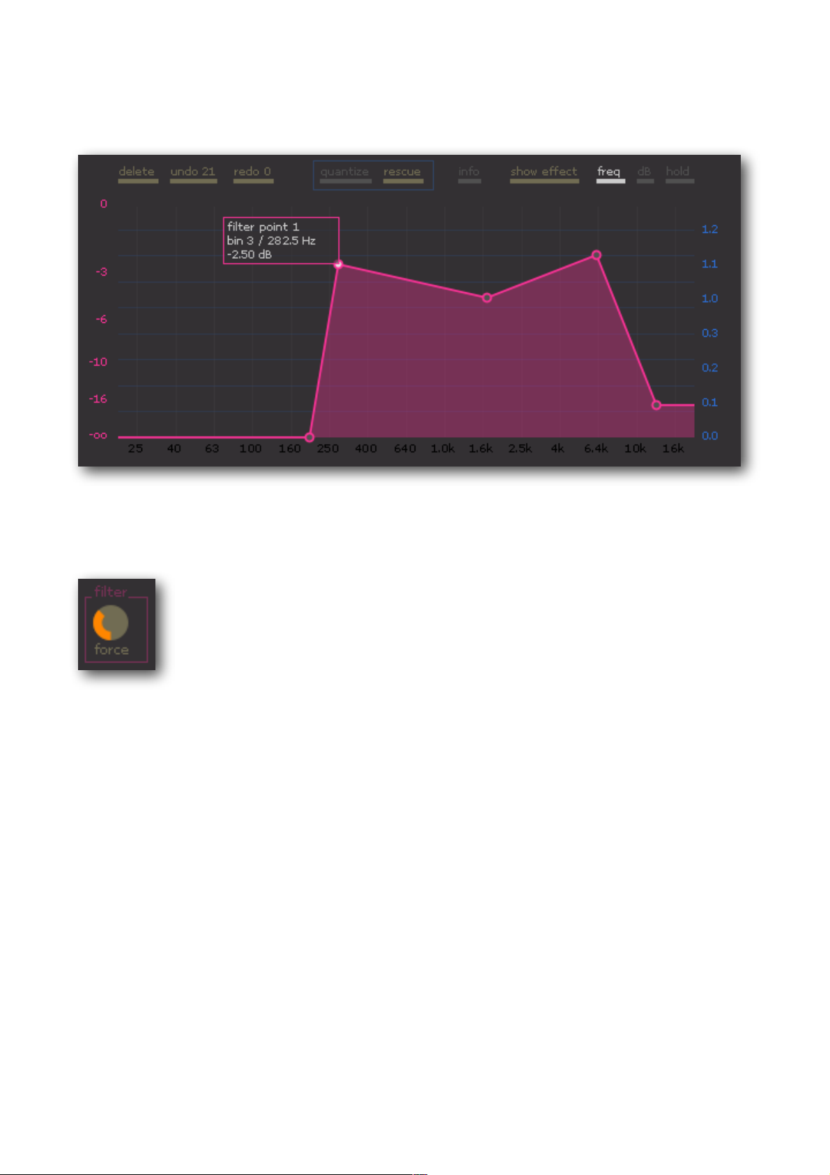
FILTER LINE
The FILTER LINE regulates the volume of the individual frequency bands. This means that the
level of any frequency area can be lowered.
With the FILTER FORCE control, the strength of the filters can be adjusted. The FILTER FORCE
controls in this respect the scale of the y-axis. A high FILTER FORCE value leads to a stronger
lowering of the level even in the top areas of the scale. On the other hand a low FILTER FORCE
value slowly lowers the level in the top area, enabling a very fine adjustment.
- page 20 -
Page 21
artificial audio ! OBELISK manual
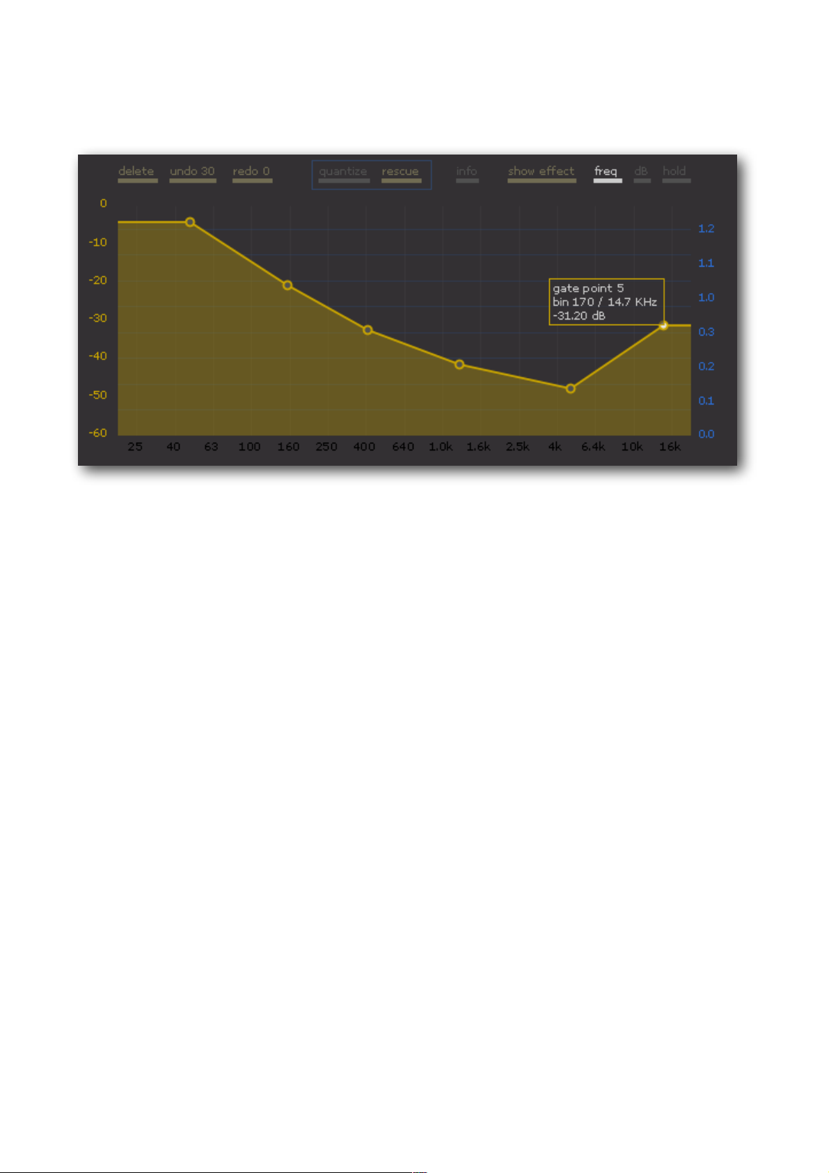
GATE LINE
The GATE LINE controls the SPECTRAL GATE. The SPECTRAL GATE is a noise gate with an
individual threshold - value for each individual frequency band. Similar to a normal noise gate, the
threshold – value determines the level at which the gate opens. Only those signals whose level
lies above the threshold value can pass through. Signals whose level remains under the threshold
value become mute. The GATE in the OBELISK functions exactly like this: for each frequency
band the GATE LINE determines the respective threshold level. Only those bands whose level lies
above the GATE LINE can pass though. All other become mute.
The scale of the GATE LINE (y - axis) exactly corresponds to the level display of the ANALYSER. If
in the ANALYSER a frequency band protrudes above the yellow GATE LINE, the GATE is opened
and the frequency band can pass through, otherwise it becomes mute.
- page 21 -
Page 22

artificial audio ! OBELISK manual
In addition to the GATE LINE there are other global GATE - Parameters:
attack " globally regulates the ATTACK TIME for all frequency bands. If the GATE of a
frequency band opens after it has become mute, the ATTACK TIME determines the
interval until the GATE is completely open.
ATTACK TIME = 0 means: the GATE opens immediately.
ATTACK TIME = 1 means: the frequency band is faded in and it takes a certain time
for the frequency band to reach its full level.
release " globally regulates the RELEASE TIME for all frequency bands. If the GATE of a
" " frequency band closes after it was open, the RELEASE TIME determines how
" " quickly the GATE will close.
" " RELEASE TIME = 0 means: the GATE closes immediately.
" " RELEASE TIME = 1 means: the frequency band will be faded out and it will take a
" " certain time for the frequency band to become completely mute.
mono/stereo " mono: in the case of a stereo signal the GATES of the left and right channels are
connected. The GATE only opens when the level of the left and right channels is
above the threshold.
stereo: the left and right channels are sent through the GATE independently. If, for
example, the level of the left channel is above the threshold and the level of the
right channel is below it, the right GATE remains closed whereas the left one
remains open.
- page 22 -
Page 23
artificial audio ! OBELISK manual
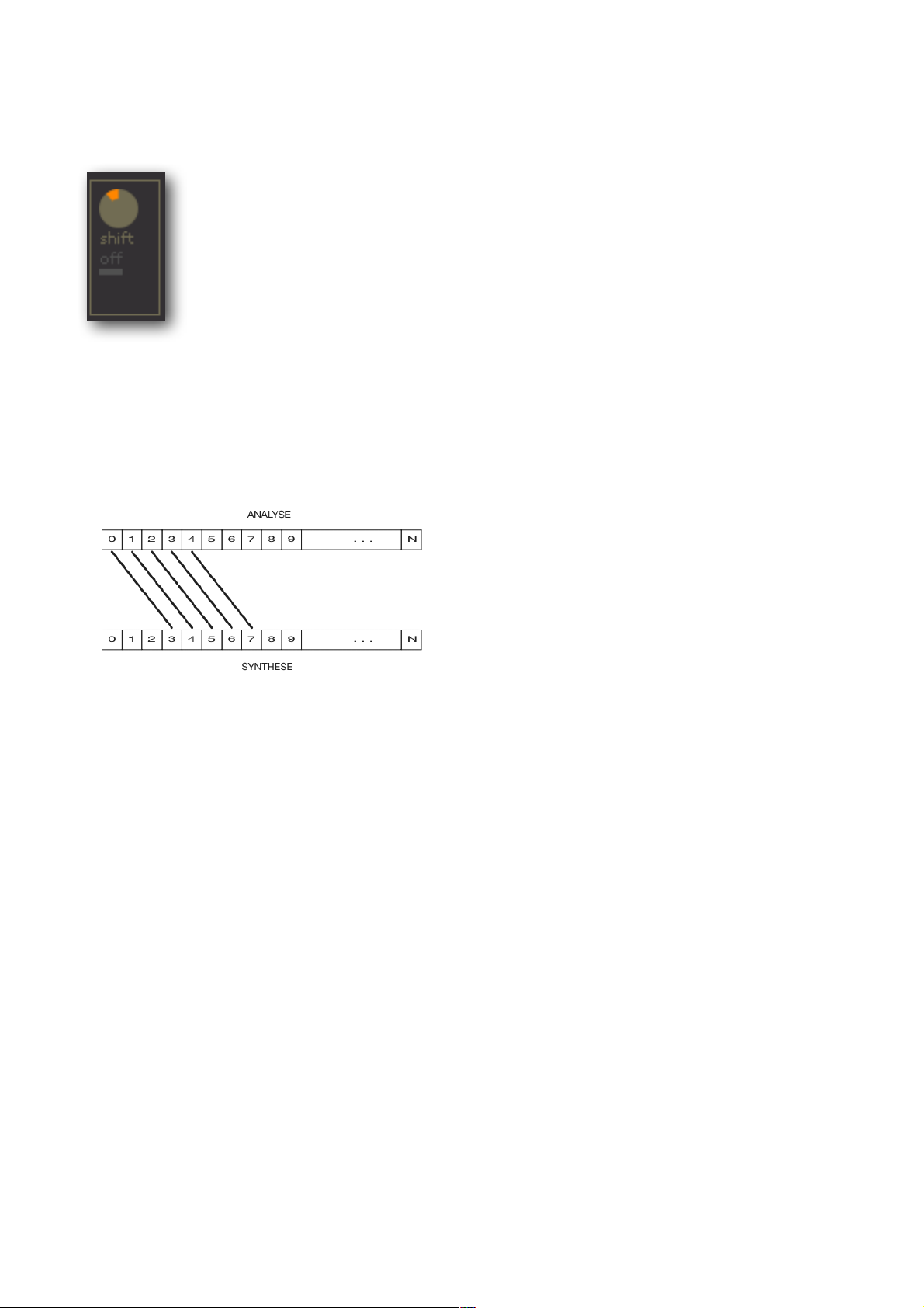
SPECTRAL SHIFT
With SPECTRAL SHIFT you can move the frequency bands up or down before they join together
again to form a music signal in the SYNTHESIS. A shift of +3 for example moves all bands three
positions to the right.
This leads to a frequency band shift, a very experimental and unusual sound effect.
- page 23 -
Page 24

artificial audio ! OBELISK manual
SETTINGS
In the settings the parameters for the SPECTRAL ANALYSIS / SYNTHESIS and the global
parameters BYPASS and EFFECT MIX can be set.
Parameters of the SPECTRAL ANALYSIS / SYNTHESIS:
overlap" determines the overlap of the audio blocks in the spectral analysis / synthesis.
" " The best audio quality and the finest resolution of the delay times can be achieved
" " with overlap = 75% (= default value).
window" selects the window function utilized in the spectral analysis / synthesis
" " (square, triangle, Henning, Hamming, Bleckman)
" " recommended setting: Hanning (= default value).
frame size" selects the block size of the audio blocks and thus determines the number of
" " frequency bands (number of frequency bands = frame size / 2). The finest
" " resolution of the delay times is achieved with frame size = 512 (=default value).
" " frame size 512 corresponds to 256 frequency bands,
" " frame size 1024 corresponds to 512 frequency bands.
effmix"" EFFECT MIX regulates the relationship between input signal and effect signal.
byp"" BYPASS switches the effect internally to bypass.
- page 24 -
Page 25
artificial audio ! OBELISK manual
MODULATION
Every LINE POINT can be modulated. 2-dimensional LFOs serve as modulation sources, of which
there is a total of 3.
2 - DIMENSIONAL LFO
In order to explain the concept of the 2-dimensional LFO, we should take a look at geometry. The
movement of a point in the plane can be depicted by two combined movements: a movement on
the x-axis and a movement on the y-axis.
According to this principal, a 2-dimensional LFO combines two individual LFOs into a 2-
dimensional LFO, where the movement of the one LFO controls the x-axis and the movement of
the second LFO the y-axis. With the aid of both the x- and the y-LFOs, movements can be
created in the plane. A movement created this way is made visible in the LFO VIEW by means of
a small ball, the LFO BALL.
The movement of an LFO BALL can be used as modulation for LINE POINTS. In this case the
movement is modulated on to one or more LINE POINTS, e.g. the LINE POINT follows the same
movement as the LFO BALL. The three different 2D-LFOs can be selected via the tags „2D-LFO
1“ to „2D-LFO 3“.
- page 25 -
Page 26

artificial audio ! OBELISK manual
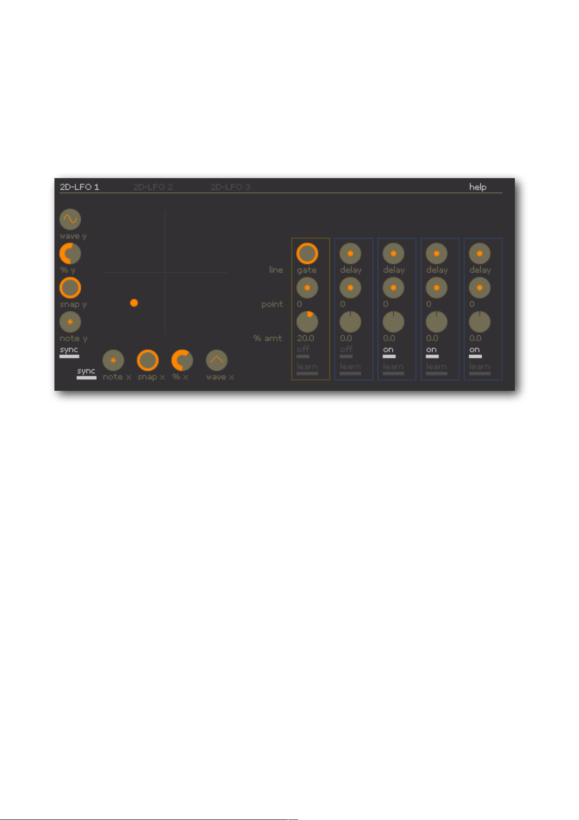
The parameters for the x- and y-movement are arranged along the two axes: the x-parameter is
on the x-axis and the y-parameter is on the y-axis.
The parameters for the x- and y-axis in detail:
wave ! selects the wave form: sinus, triangle, square, saw tooth up, saw tooth down,
sample & hold (random).
% (amount)" determines how far the LFO BALL moves away from the centre.
snap " the first zero run of the wave form can be “clicked into” an adjustable beat-position.
The position is between „1.1“ and „4.4“. A value of „2.4“ for example means: 2.
beat / 4. semiquaver. As a result LFO modulations can be placed in an exact
rhythmic manner. The LFO oscillation is thus determined for the total time line of
the song and can be exactly reproduced at every song start.
1.1
2.1 3.1 4.1
"
snap = 2.4Song start
Hz" " sets the desired frequency of the LFO.
- page 26 -
Page 27

artificial audio ! OBELISK manual
sync" activates the tempo control of the LFO. The LFO can thus be synchronized to the
external or internal tempo. The Hz–control becomes the NOTE-control.
note" if sync is activated, the NOTE – control appears. This allows for a regulation of the
note values or bar intervals in order to determine the frequency of the LFO
oscillation. The depiction „N. N. N“ means „bars . beats . semiquavers“. For
example: „1.3.2“ means: the LFO requires a bar plus three beats plus 3
semiquavers for a whole wave run.
- page 27 -
Page 28

artificial audio ! OBELISK manual
MODULATION OF LINE POINTS
If a LINE POINT is modulated by an LFO BALL, this can be recognized by the fact that the
EFFECT PLANE separates from the POINT LINE and completes an own movement. The top edge
of the EFFECT PLANE forms a new line out of the modulated LINE POINTS and thus determines
the modulated parameter values. For the calculation of the effects, those parameters are now
used that result from the top edge of the EFFECT PLANE.
!!
No modulation"" """ right hand point is modulated
The LINE POINTS themselves do not move, only the EFFECT PLANE changes. One can therefore
always recognize and change the (unmodulated) position of the points.
As the modulation allows a modulated LINE POINT to move in all directions, the sequence of the
LINE POINTS on the x-axis (horizontally) may change. This may give rise to a completely different
line form which makes this type of modulation appealing.
- page 28 -
Page 29

EFFECT LINE
LINE POINT
AMOUNT
LEARN MODE
artificial audio ! OBELISK manual
MODULATION TARGETS
In order to modulate a LINE POINT, you have to assign the respective point to an LFO as a
modulation target. The MODULATION TARGETS determine which point is to be modulated by
which LFO and to what extent. Every 2D-LFO has got five MODULATION TARGETS and thus can
modulate up to 5 LINE POINTS.
Each LINE POINT can be exactly identified by its colour (blue = delay, red = feedback etc.) and its
number (0 - 9).
In order to modulate the movement of an LFO BALL on to a LINE POINT, you have to proceed as
follows:
By clicking on learn the LEARN MODE of the TARGET is activated. The TARGET blinks. You now
have to click in the ANALYSER POINT VIEW on the LINE POINT to be modulated. The TARGET
then automatically sets the selected LINE POINT as a modulation target. The parameters line and
point now correspond to the target point. The AMOUNT - control (% amt) determines the strength
of the modulation. A negative AMOUNT – value causes counter movement to the LFO BALL: if the
LFO BALL moves up or to the right, the modulated LINE POINT moves down or to the left.
The values line and point can also be set manually with the controls. This, however, is rather
tedious because you first of all have to find out the respective number of the LINE POINT in the
POINT INFO BOX of this LINE POINT.
- page 29 -
Page 30

artificial audio ! OBELISK manual
The TARGET - Parameter in detail:
line!! ! the line type of the target point (DELAY, FEEDBACK, FILTER, GATE)
point!! ! the point number (0 - 9)
% amt" " the modulation strength (-100% to +100%)
on / off!! switches modulation on / of
learn!! ! activates/ deactivates the LEARN MOD
- page 30 -
Page 31

artificial audio ! OBELISK manual
MISCELLANEOUS REMARKS
AUTOMATION OF PARAMETERS
All OBELISK parameters can be automated in the sequencer. Parameters can be easily recorded
in the sequencer by activating the „learn“ mode of the sequencer and then changing the
respective parameter.
SAMPLE RATES
OBELISK works with arbitrary sample rates up to 192 KHz.
BUFFER SIZES
OBELISK works with arbitrary buffer sizes from 32 to 8192 samples. If the buffer size exceeds
2048, the display of the real-time analyser will be slowed down because OBELISK does not
receive enough audio data from the sequencer to calculate a fluent display.
LATENCY
OBELISK has a constant latency value of 1024 samples.
- page 31 -
 Loading...