

Artic Cat 700 diesel SD ATV Service Manual

For Discount Arctic Cat Parts Call 606-678-9623 or 606-561-4983
FOREWORD
This Arctic Cat Service Manual contains service, maintenance, and troubleshooting information for the 2011
Arctic Cat 700 Diesel SD ATV. The complete manual is designed to aid service personnel in service-oriented
applications.
When using this manual as a guide, the technician should use discretion as to how much disassembly is needed
to correct any given condition.
The service technician should become familiar with the operation and construction of each component or system
by carefully studying the complete manual. This manual will assist the service technician in becoming more aware
of and efficient with servicing procedures. Such efficiency not only helps build consumer confidence but also saves
time and labor.
All Arctic Cat ATV publications and decals display specific symbols to emphasize important information. The
symbol ! WARNING identifies personal safety-related information. Be sure to follow the directive because it
deals with the possibility of severe personal injury or even death. A CAUTION identifies unsafe practices
which may result in ATV-related damage. Follow the directive because it deals with the possibility of damaging
part or parts of the ATV. The symbol NOTE: identifies supplementary information worthy of particular atten-
tion. The symbol
efficiency and to improve clarity.
At the time of publication, all information, photographs, and illustrations were technically correct. Some photographs used in this manual are used for clarity purposes only and are not designed to depict actual conditions.
Because Arctic Cat Inc. constantly refines and improves its products, no retroactive obligation is incurred.
AT THIS POINT directs the technician to certain and specific procedures to promote
All materials and specifications are subject to change without notice.
Keep this manual accessible in the shop area for reference.
Product Service and
Warranty Department
Arctic Cat Inc.
© 2011 Arctic Cat Inc. January 2011
®™ Trademarks of Arctic Cat Inc., Thief River Falls, MN 56701
www.mymowerparts.com
For Discount Arctic Cat Parts Call 606-678-9623 or 606-561-4983
Note: To navigate through this manual, use the PAGE UP/PAGE DOWN buttons on the keyboard, click on the
Table of Contents bookmarks on the left side of the screen, or click the blue text below. To return to this page,
click the Manual Table of Contents button at the bottom of each page.
Click on the blue text to go.
TABLE OF CONTENTS
General Information ........................................................2
General Specifications.................................................. 2
Torque Specifications.................................................... 2
Torque Conversions (ft-lb/N-m)..................................... 3
Break-In Procedure ...................................................... 3
Fuel - Oil - Lubricant ..................................................... 4
Genuine Parts............................................................... 5
Preparation For Storage ............................................... 5
Preparation After Storage ............................................. 5
Periodic Maintenance/Tune-Up....................................... 6
Periodic Maintenance Chart ......................................... 6
Lubrication Points ......................................................... 7
Air Filter ........................................................................ 7
Valve Clearance............................................................ 8
Muffler/Spark Arrester .................................................. 8
Adjusting Throttle Cable ............................................... 8
Engine RPM (Idle) ........................................................ 9
Engine Oil - Filter.......................................................... 9
Transmission Lubricant ............................................... 10
Front Differential/Rear Drive Lubricant ....................... 10
Tires............................................................................ 11
Driveshaft/Coupling .................................................... 11
Nuts/Cap Screws/Screws/Bolts .................................. 11
Injector Timing ............................................................ 11
Lights .......................................................................... 11
Shift Lever................................................................... 13
Frame/Welds/Racks.................................................... 13
Hydraulic Brake Systems............................................ 13
Burnishing Brake Pads ............................................... 15
Coolant ....................................................................... 15
Checking/Replacing V-Belt ......................................... 16
Fuel Filter.................................................................... 17
Engine/Transmission..................................................... 19
Specifications ............................................................. 19
Removing Engine/Transmission ................................. 20
Top-Side Components ................................................ 24
Left-Side Components................................................ 53
Right-Side Components ............................................. 60
Center Components ................................................... 75
Installing Engine/Transmission ................................... 89
Troubleshooting .......................................................... 95
Fuel/Lubrication/Cooling ............................................... 98
Diesel Fuel Injection System ...................................... 98
Lift Pump .................................................................... 98
Unit Injectors............................................................... 99
Injector Timing ............................................................ 99
Fuel Filter.................................................................... 99
Fuel Solenoid Assembly ............................................. 99
Fuel Tank .................................................................. 100
Fuel/Vent Hoses ....................................................... 101
Oil Filter/Oil Pump..................................................... 101
Testing Oil Pump Pressure ....................................... 101
Liquid Cooling System.............................................. 101
Radiator .................................................................... 102
Hoses/Thermostat .................................................... 103
Fan............................................................................ 103
Water Pump.............................................................. 103
Troubleshooting ........................................................ 103
Electrical System......................................................... 104
Battery.......................................................................104
Testing Electrical Components ..................................105
Switches....................................................................105
Accessory Receptacle/Connector .............................105
Brakelight Switch (Auxiliary) ......................................105
Brakelight Switch (Handlebar Control) ......................106
Cooling Fan Switch ...................................................106
Engine Coolant Temperature (ECT) Switch/
Thermistor ..............................................................107
Glow Plug Controller/Relay .......................................107
Fan Motor..................................................................108
Fuse Block/Power Distribution Module......................108
Electronic Speedometer Speed Sensor ....................109
Ignition Switch ...........................................................110
Handlebar Control Switches......................................110
Drive Select Switch ...................................................111
Front Drive/Differential Lock Actuator........................111
Starter/Starter Solenoid ............................................112
Starter Relay .............................................................113
Alternator/Regulator ..................................................113
Headlights .................................................................114
Taillight - Brakelight ...................................................115
Fuel Solenoid ............................................................115
Troubleshooting.........................................................116
Drive System...............................................................117
Front Drive Actuator ..................................................117
Front Differential ........................................................118
Drive Axles ................................................................131
Rear Gear Case ........................................................134
Hub............................................................................135
Hydraulic Brake Caliper.............................................136
Troubleshooting Drive System...................................140
Troubleshooting Brake System..................................140
Suspension .................................................................141
Shock Absorbers.......................................................141
Front A-Arms.............................................................142
Rear A-Arms .............................................................144
Wheels and Tires ......................................................146
Troubleshooting.........................................................147
Steering/Frame............................................................148
Steering Post/Tie Rods .............................................148
Handlebar Grip..........................................................150
Steering Knuckles .....................................................150
Measuring/Adjusting Toe-In.......................................152
Front Rack.................................................................154
Front Bumper Assembly ............................................154
Front Body Panel/Side Panels...................................154
Footrests ...................................................................157
Belly Panel ................................................................157
Exhaust System ........................................................158
Rear Body Panel/Rack..............................................158
Adjusting Headlight ...................................................159
Taillight Assembly......................................................159
Seat...........................................................................159
Troubleshooting.........................................................160
Controls/Indicators ......................................................161
Hand Brake Lever/Master Cylinder Assembly ...........161
Throttle Control .........................................................162
Shift Lever .................................................................163
Speedometer/Tachometer/LCD.................................163
www.mymowerparts.com
1

For Discount Arctic Cat Parts Call 606-678-9623 or 606-561-4983
General Information
General Specifications
FUEL INJECTION
Type Lombardini Unit Injectors
Idle RPM (engine warm) 800-900
Throttle Cable Free-Play (at lever) 1/4 in.
ELECTRICAL
Glow Plug Type Lombardini
Alternator Denso 12V/40 Amp
CHASSIS
Brake Type Hydraulic w/Brake Lever Lock and
Tire Size Front - 25 x 8-12
Tire Inflation Pressure 0.35 kg/cm² (5 psi)
Fuel Tank Capacity 20.81 L (5.5 U.S. gal.)
Coolant Capacity 5.6 L (5.9 U.S. qt)
Front Differential Capacity 275 ml (9.3 fl oz)*
Rear Drive Capacity 250 ml (8.5 fl oz)*
Engine Oil Capacity (with filter) 2.0 L (2.1 U.S. qt)
Engine Oil Capacity (without filter) 1.9 L (2.0 U.S. qt)
Transmission Capacity 600 ml (20.3 fl oz)
Fuel (recommended) Biodiesel Blend up to 20% (B20)/
Engine Oil (recommended) SAE 10W-40
Differential/Rear Drive Lubricant SAE Approved 80W-90 Hypoid
Transmission Lubricant SAE Approved 80W-90 Hypoid
Drive Belt Width (minimum) 31.25 mm (1.23 in.)
Brake Fluid DOT 4
Taillight/Brakelight 12V/8W/27W
Headlight 12V/27W (2)
Auxiliary Brake
Rear - 25 x 10-12
MISCELLANY
42-50 Cetane Diesel - #1 or #2/JP
5 or JP 8 Turbine
Specifications subject to change without notice.
* One inch below plug threads.
Torque Specifications
STEERING COMPONENTS
Part Part Bolted To
Handlebar Cap Steering Post 20 27
Steering Post Bearing Housing Frame 20 27
Steering Post Bearing Flange Frame 20 27
Tie Rod End Knuckle/Steering Post 30 41
EXHAUST COMPONENTS
Exhaust Pipe Exhaust Manifold 14 19
Spark Arrester Muffler 48
ELECTRICAL COMPONENTS
Ground Wire Transmission 8 11
CHASSIS COMPONENTS
Shift Lever*** Shift Axle 8 11
Tor que
ft-lb N-m
5
in.-lb
www.mymowerparts.com
DRIVE TRAIN COMPONENTS
Tor que
Part Part Bolted To
Front Mounting Bracket Engine 20 27
Engine Mount (Upper)** Frame 35 48
Engine Mount (Front/Rear) Frame 20 27
Front Differential*** Frame/Differential Bracket 38 52
Rear Drive Gear Case Frame 38 52
Input Housing Gear Case Housing 23 31
Output Drive Yoke Nut* Output Shaft 72 98
Differential Housing Cover** Differential Housing 23 31
Drive Bevel Gear Retaining
Nut**
Secondary Drive/Bevel Gear
Shaft
Pinion Housing Gear Case 25 34
Ring Gear/Thrust Button* Gear Case 8 11
Gear Case Cover Gear Case 23 31
Lock Collar Differential Housing 125 170
Hub Nut Shaft/Axle (min) 200 272
Drain Plug Front Differential/Rear Drive 42
Fill Plug Front Differential/Rear Drive 16 22
Oil Drain Plug Engine 18 24
Wheel Hub 45 61
BRAKE COMPONENTS
Brake Disc*** Hub 15 19
Brake Hose Caliper 20 27
Brake Hose Master Cylinder 20 27
Brake Hose Auxiliary Brake Cylinder 20 27
Auxiliary Brake Pedal Lever Axle 25 34
Caliper Holder Knuckle 20 27
Auxiliary/Hydraulic Caliper**** Knuckle 20 27
SUSPENSION COMPONENTS (Front)
A-Arm Frame 50 68
Ball Joint Cap Screw Knuckle 35 48
Shock Absorber Frame 50 68
Shock Absorber Upper A-Arm 50 68
SUSPENSION COMPONENTS (Rear)
A-Arm Frame 50 68
Shock Absorber (Upper) Frame 50 68
Shock Absorber (Lower) Lower A-Arm 20 27
Knuckle A-Arm 50 68
Secondary Output Shaft 87 118
Transmission Case 80 108
ft-lb
in.-lb
Nm
5
* w/Red Loctite #271
** w/Green Loctite #609
*** w/Blue Loctite #243
**** “Patch-Lock”
2

For Discount Arctic Cat Parts Call 606-678-9623 or 606-561-4983
ENGINE/TRANSMISSION
Part Part Bolted To
Transmission Mounting
Plate
Connecting Rod Cap Connecting Rod (4 Steps) 29 40
Main Bearing Cap Engine Block (6 Steps) 44 60
Rocker Arm Support Cylinder Head 29 40
Cylinder Head Cylinder (5 Steps) 35 48
Valve Cover Cylinder Head 6.5 9
Driven Pulley Nut Fixed Face 125 170
Drive Clutch Flywheel/PTO Shaft 40 54
Movable Drive Face* Fixed Drive Hub 85 116
Oil Pump Engine Block 22 30
Output Shaft* Output Shaft Coupler 20 27
Output Shaft Nut* Output Shaft 80 108
Starter V-Belt Housing 35 48
Flywheel/PTO Shaft Crankshaft 40 54
Crankshaft Pulley Timing Belt Drive Pulley 9 12
Chamber Ring Nut Chamber (Step 1)
Glow Plug Cylinder Head 18 24
Crankshaft Pulley*** Crankshaft 260 354
Timing Belt Idler Nut Engine Block 29 39
V-Belt Cover V-Belt Housing 9 12
V-Belt Housing Crankcase/Transmission 25 34
Fuel Rail Unit Injectors 36
Gear Case (Left) Gear Case (Right) 8 11
Oil Pan Crankcase 7 10
Oil Pan Cover Oil Pan 7 10
Crankshaft Seal/Flange Engine Block 9 12
Camshaft Support Housing Cylinder Head 7 10
Fuel Injector Control Rack Unit Injector 11
Unit Injector Retainer Nut Cylinder Head (5 Steps) 15 20
Camshaft Drive Pulley Camshaft 59 80
Lift Pump Eccentric Camshaft 59 80
Water Pump Engine Block 22 30
Crankcase/Transmission 35 48
(Step 2)7213098177
* w/Red Loctite #271
*** w/Blue Loctite #243
Tor que
ft-lb N-m
4
in.-lb
1.2
in.-lb
Torque Conversions
(ft-lb/N-m)
ft-lb N-m ft-lb N-m ft-lb N-m ft-lb N-m
1 1.4 26 35.4 51 69.4 76 103.4
2 2.7 27 36.7 52 70.7 77 104.7
3 4.1 28 38.1 53 72.1 78 106.1
4 5.4 29 39.4 54 73.4 79 107.4
5 6.8 30 40.8 55 74.8 80 108.8
6 8.2 31 42.2 56 76.2 81 110.2
7 9.5 32 43.5 57 77.5 82 111.5
8 10.9 33 44.9 58 78.9 83 112.9
9 12.2 34 46.2 59 80.2 84 114.2
10 13.6 35 47.6 60 81.6 85 115.6
11 15 36 49 61 83 86 117
12 16.3 37 50.3 62 84.3 87 118.3
13 17.7 38 51.7 63 85.7 88 119.7
14 19 39 53 64 87 89 121
15 20.4 40 54.4 65 88.4 90 122.4
16 21.8 41 55.8 66 89.8 91 123.8
17 23.1 42 57.1 67 91.1 92 125.1
18 24.5 43 58.5 68 92.5 93 126.5
19 25.8 44 59.8 69 93.8 94 127.8
20 27.2 45 61.2 70 95.2 95 129.2
21 28.6 46 62.6 71 96.6 96 130.6
22 29.9 47 63.9 72 97.9 97 131.9
23 31.3 48 65.3 73 99.3 98 133.3
24 32.6 49 66.6 74 100.6 99 134.6
25 34 50 68 75 102 100 136
Break-In Procedure
A new ATV and an overhauled ATV engine require a
“break-in” period. The first 10 hours (or 200 miles) are
most critical to the life of this ATV. Proper operation
during this break-in period will help assure maximum
life and performance from the ATV.
During the first 10 hours (or 200 miles) of operation,
always use less than 1/2 throttle. Varying the engine
RPM during the break-in period allows the components to “load” (aiding the mating process) and then
“unload” (allowing components to cool). Although it
is essential to place some stress on the engine components during break-in, care should be taken not to
overload the engine too often. Do not pull a trailer or
carry heavy loads during the 10-hour break-in period.
When the engine starts, allow it to warm up properly.
Idle the engine several minutes until the engine has
reached normal operating temperature.
During the break-in period, a maximum of 1/2 throttle
is recommended; however, brief full-throttle accelerations and variations in driving speeds contribute to
good engine break-in.
www.mymowerparts.com
3
For Discount Arctic Cat Parts Call 606-678-9623 or 606-561-4983
After the completion of the break-in period, the engine
oil and oil filter should be changed. Other maintenance
after break-in should include checking of all prescribed adjustments and tightening of all fasteners.
Fuel - Oil - Lubricant
NOTE: Arctic Cat recommends the use of genuine Arctic Cat lubricants.
RECOMMENDED FUEL
The recommended fuel to use is biodiesel blend up to
20% (B20), #1 or #2 diesel fuel (42-50 cetane), or JP 5
or JP 8 turbine fuel. At temperatures above -10° C (14°
F), use #2 diesel fuel or a biodiesel blend up to 20%.
At temperatures at or below -10° C (14° F), use #1 diesel fuel. Diesel fuel with a minimum cetane number
below 42 should not be used.
CAUTION
Never use biodiesel blends at temperatures at or
below -10° C (14° F).
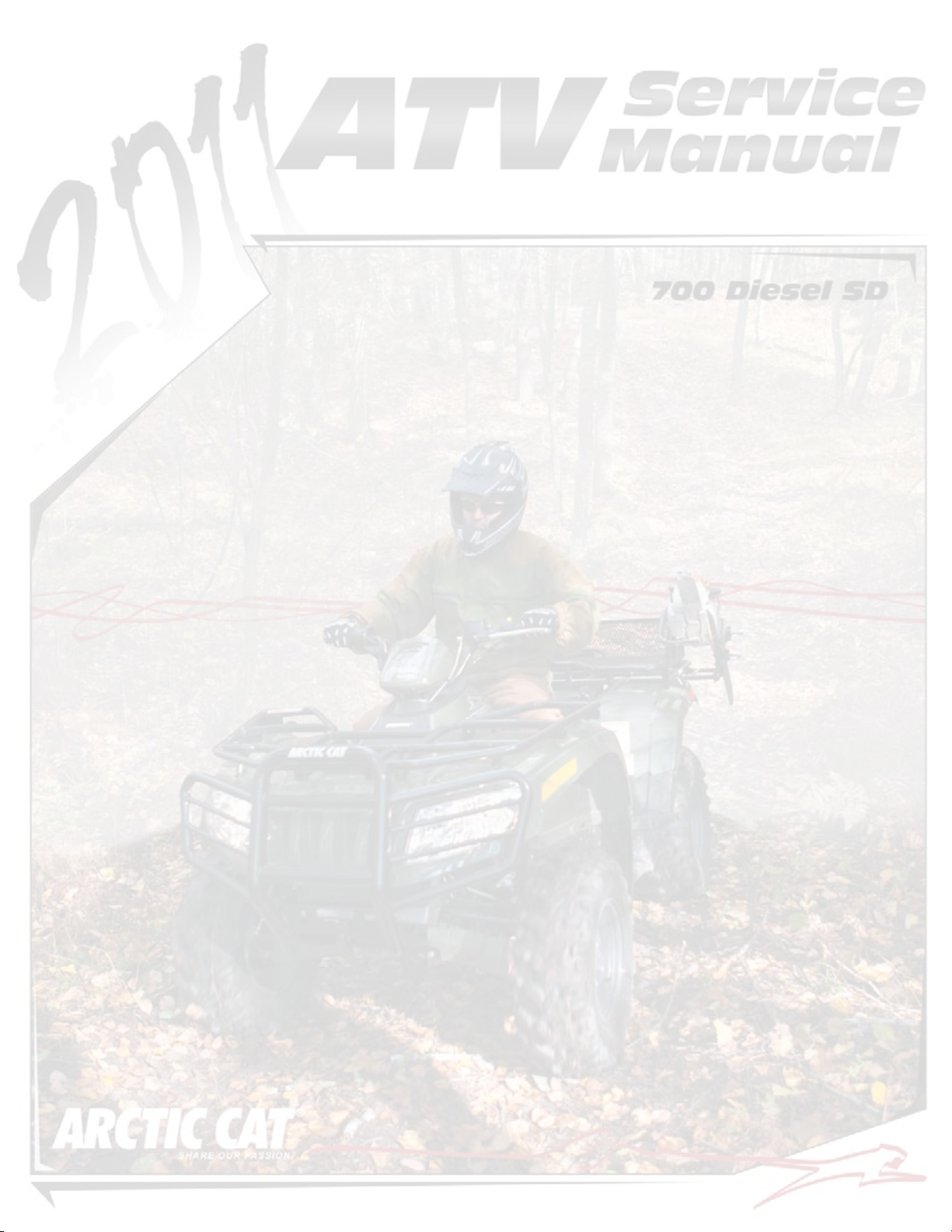
RECOMMENDED ENGINE OIL
CAUTION
Any lubricant used in place of the recommended
lubricant could cause serious transmission damage.
RECOMMENDED FRONT DIFFERENTIAL/REAR DRIVE LUBRICANT
The recommended lubricant is Arctic Cat Gear Lube
or an equivalent gear lube which is SAE approved
80W-90 hypoid. This lubricant meets all of the lubrication requirements of the Arctic Cat ATV front differentials and rear drives.
CAUTION
Any lubricant used in place of the recommended
lubricant could cause serious front differential/rear
drive damage.
FILLING FUEL TANK
! WARNING
Always fill the fuel tank in a well-ventilated area.
Never add fuel to the ATV fuel tank near any open
flames or with the engine running. DO NOT SMOKE
while filling the fuel tank.
The recommended oil to use is an oil which is rated SJ/
CF under API service classification. These oils meet
all of the lubrication requirements of the Arctic Cat
engine. The recommended engine oil viscosity is SAE
10W-40. Ambient temperature should determine the
correct weight of oil. See the viscosity chart or an
authorized Arctic Cat ATV dealer for details.
OILCHARTE
CAUTION
Any oil used in place of the recommended oil could
cause serious engine damage.
ATV0049B
Since fuel expands as its temperature rises, the fuel
tank must be filled to its rated capacity only. Expansion room must be maintained in the tank particularly
if the tank is filled with cold fuel and then moved to a
warm area.
! WARNING
Do not overflow fuel when filling the fuel tank. A fire
hazard could materialize. Always allow the engine to
cool before filling the fuel tank.
Tighten the fuel tank cap securely after filling the tank.
RECOMMENDED TRANSMISSION LUBRICANT
The recommended transmission lubricant is SAE
approved 80W-90 hypoid. This lubricant meets all of
the lubrication requirements of the ATV transmission.
www.mymowerparts.com
4
! WARNING
Do not over-fill the fuel tank.

For Discount Arctic Cat Parts Call 606-678-9623 or 606-561-4983
Genuine Parts
When replacement of parts is necessary, use only genuine Arctic Cat ATV parts. They are precision-made to
ensure high quality and correct fit. Refer to the appropriate Illustrated Parts Manual for the correct part
number, quantity, and description.
8. Disconnect the battery cables; then remove the
battery, clean the battery posts and cables, and
store in a clean, dry area.
9. Store the ATV indoors in a level position.
CAUTION
Avoid storing outside in direct sunlight and avoid
using a plastic cover as moisture will collect on the
ATV causing rusting.
Preparation For Storage
CAUTION
Prior to storing the ATV, it must be properly serviced
to prevent rusting and component deterioration.
Arctic Cat recommends the following procedure to
prepare the ATV for storage.
1. Clean the seat cushion (cover and base) with a
damp cloth and allow it to dry.
2. Clean the ATV thoroughly by washing dirt, oil,
grass, and other foreign matter from the entire
ATV. Allow the ATV to dry thoroughly. DO NOT
get water into any part of the engine or air intake.
3. Fill the fuel tank with fresh #1 or #2 diesel fuel
(according to ambient temperatures); then add a
quality anti-microbial additive. Run the engine in
a well-ventilated area for several minutes to make
sure fresh, treated fuel is circulated throughout the
entire injection system.
CAUTION
DO NOT store the ATV with biodiesel (B20) in the fuel
system. Severe damage to the fuel system may
occur.
4. Plug the exhaust hole in the muffler with a clean
cloth.
5. Apply light oil to the upper steering post bushing
and plungers of the shock absorbers.
6. Tighten all nuts, bolts, cap screws, and screws.
Make sure rivets holding components together are
tight. Replace all loose rivets. Care must be taken
that all calibrated nuts, cap screws, and bolts are
tightened to specifications.
Preparation After
Storage
Taking the ATV out of storage and correctly preparing
it will assure many miles and hours of trouble-free riding. Arctic Cat recommends the following procedure
to prepare the ATV.
1. Clean the ATV thoroughly.
2. Clean the engine. Remove the cloth from the muffler.
3. Check all control wires and cables for signs of
wear or fraying. Replace if necessary.
4. Change the engine oil and filter.
5. Check the coolant level and add properly mixed
coolant as necessary.
6. Charge the battery; then install. Connect the battery cables.
CAUTION
The ignition switch must be in the OFF position prior
to installing the battery or damage may occur to the
electrical system.
CAUTION
Connect the positive battery cable first; then the negative.
7. Check the entire brake systems (fluid level, pads,
etc.), all controls, headlights, taillight, brakelight,
and headlight aim; adjust or replace as necessary.
8. Tighten all nuts, bolts, cap screws, and screws
making sure all calibrated nuts, cap screws, and
bolts are tightened to specifications.
7. Fill the cooling system to the bottom of the stand
pipe in the filler neck with properly mixed coolant.
www.mymowerparts.com
9. Check tire pressure. Inflate to recommended pressure as necessary.
10. Make sure the steering moves freely and does not
bind.
5

For Discount Arctic Cat Parts Call 606-678-9623 or 606-561-4983
Periodic Maintenance/
Tune-Up
NOTE: Some photographs and illustrations used
in this section are used for clarity purposes only
and are not designed to depict actual conditions.
Periodic Maintenance
Chart
A = Adjust L = Lubricate
C = Clean R = Replace
I = Inspect
Initial Service
Item
Battery I I C
Fuses/Relays/PDM I I R
Air Filter I R R
Valve Clearance IA
Muffler/Spark Arrester CR
Fuel/Vent Hoses I R
Fuel Injectors IA
Throttle Cable I C-L A-R
Engine Oil Level I
Engine Oil/Filter Replace after initial 300 miles. R R
Front Differential/Rear Drive Lubricant I R (4 Yrs)
Transmission Lubricant I I R (4 Yrs)
Tires/Air Pressure I R
Steering Components I I R
V-B elt I l R
Suspension (Ball joint boots, drive axle
boots front and rear, tie rods,
differential and rear drive bellows)
Nuts/Cap Screws/Screws/Bolts I I A
Injector Timing IA
Headlight/Taillight-Brakelight I R
Switches I R
Shift Lever IA-L
Handlebar Grips R
Handlebars I R
Gauges/Indicators I R
Frame/Welds/Racks I I l
Electrical Connections lC
Complete Brake System
(Hydraulic & Auxiliary)
Brake Pads I R
Brake Fluid I R
Brake Hoses I I R (4 Yrs)
Coolant/Cooling System I Replace coolant every 2 years.
Timing Belt R
Alternator Belt I I
After Break-In
(First Month or
100 Miles)
Il* R
IC L-R
Every
Month or
Every 100
Miles
Every 3
Months or
Every 300
Miles
Every 6
Months or
Every 500
Miles
Every Year
or Every
1250
Miles
Every 2
Years or
Every 5000
Miles
As
Needed
* Service/Inspect more frequently when operating in adverse conditions.
www.mymowerparts.com
6
For Discount Arctic Cat Parts Call 606-678-9623 or 606-561-4983
Lubrication Points
It is advisable to lubricate certain components periodically to ensure free movement. Apply light oil to the
components using the following list as reference.
A. Throttle Lever Pivot/Cable Ends
B. Brake Lever Pivot/Cable Ends
C. Auxiliary Brake Cable Ends
D. Shift Lever Cable End
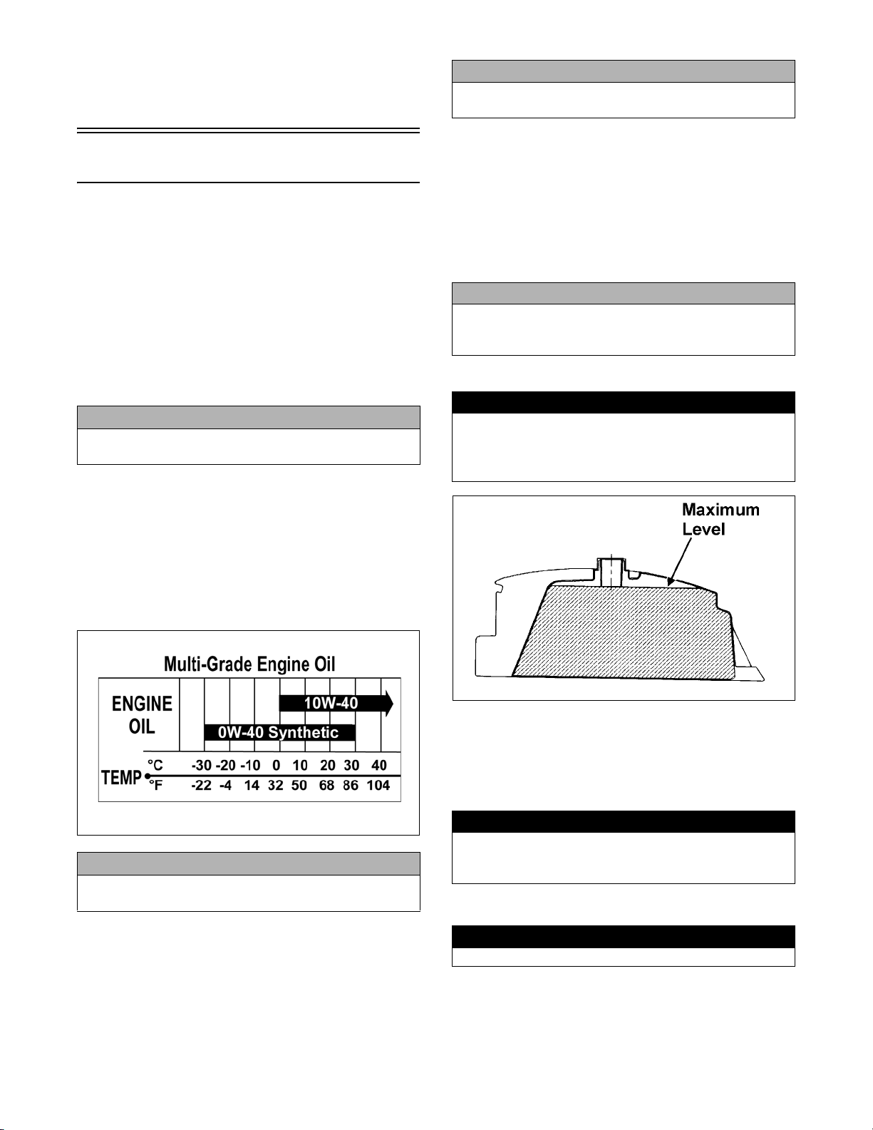
Air Filter
CLEANING AND INSPECTING FILTER
2. Remove the dry-paper air filter. Do not remove the
cotton-fabric safety element at this time.
DE007
3. Clean dust and debris from the air filter housing;
then remove the cotton-fabric safety element using
care not to allow dirt and debris to enter the
engine.
CAUTION
Failure to inspect the air filter frequently if the vehicle is used in dusty, wet, or muddy conditions can
damage the engine.
NOTE: This ATV is equipped with a dry-paper air
filter and a cotton-fabric safety element.
DE014A
1. Open the air filter access cover and remove the operator’s seat; then rotate the air filter housing cover counterclockwise and remove from the filter housing.
DE008
4. Lightly tap the dry-paper air filter to dislodge the
dirt and dust. Do not use compressed air.
5. Insert a suitable light into the dry-paper air filter and
look for any “pin-points” of light shining out of the
filter medium. A bright “pin-point” of light indicates
a hole and the filter element must be replaced.
A torn air filter can cause damage to the engine. Dirt and
dust may enter the engine if the element is torn. Carefully
examine the element for tears before and after cleaning
www.mymowerparts.com
DE006A
it. Replace the element with a new one if it is torn.
DE028A
CAUTION
7
For Discount Arctic Cat Parts Call 606-678-9623 or 606-561-4983
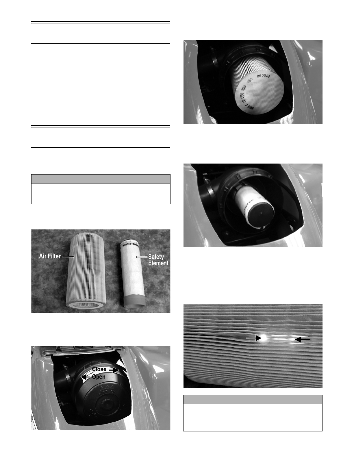
6. Check the safety element for signs of dirt build-up.
If dirt is present on the element, it indicates a leak
or hole in the dry-paper air filter element and both
elements must be replaced.
7. Install the safety element; then install the drypaper air filter.
8. Check the drain valve in the air filter housing
cover for dirt, deterioration, or poor sealing. Clean
or replace as required.
DE015
9. Install the air filter housing cover (drain facing
downward) and lock it in place by turning clockwise.
1. Remove the three cap screws securing the spark
arrester assembly to the muffler; then loosen and
remove the arrester.
CF105A
2. Using a suitable brush, clean the carbon deposits
from the screen taking care not to damage the
screen.
NOTE: If the screen or gasket is damaged in any
way, it must be replaced.
3. Install the spark arrester assembly with gasket;
then secure with three cap screws. Tighten to 48
in.-lb.
DE006A
Valve Clearance
To check/adjust valve clearance, see Top-Side Components in Engine/Transmission.
Muffler/Spark Arrester
Adjusting Throttle Cable
To adjust the throttle cable free-play, follow this procedure.
1. Slide the rubber boot away; then loosen the jam
nut from the throttle cable adjuster.
AL611D
2. Turn the adjuster until the throttle cable has proper
free-play of 1/4 in. at the lever.
The muffler has a spark arrester which must be periodically cleaned. At the intervals shown in the Periodic
Maintenance Chart, clean the spark arrester using the
following procedure.
! WARNING
Wait until the muffler cools to avoid burns.
8
www.mymowerparts.com

For Discount Arctic Cat Parts Call 606-678-9623 or 606-561-4983
ATV-0047C
3. Tighten the jam nut against the throttle cable
adjuster securely; then slide the rubber boot over
the adjuster.
Engine RPM (Idle)
NOTE: The idle RPM is not adjustable on the 700
Diesel.
Engine Oil - Filter
Change the engine oil and oil filter at the scheduled
intervals. The engine should always be warm when the
oil is changed so the oil will drain easily and completely.
1. Park the ATV on level ground.
2. Remove the engine oil filler cap.
DE017A
4. Remove the right-side engine cover.
5. Using a suitable filter wrench, remove the oil filter.
NOTE: Clean up any excess oil after removing
the filter.
6. Apply oil to a new filter O-ring and check to make
sure it is positioned correctly; then install the new
oil filter. Tighten until contact is made; then
tighten an additional 3/4 turn.
DE025A
3. Remove the drain plug from the bottom of the
engine and drain the oil into a drain pan.
www.mymowerparts.com
DE018
NOTE: Install a new O-ring each time the filter is
replaced.
7. Install the engine drain plug and tighten to 18 ft-lb.
Pour the specified amount of the recommended oil
in the filler hole. Install the oil filler cap.
CAUTION
Any oil used in place of the recommended oil could
cause serious engine damage. Do not use racing,
vegetable, non-detergent, and castor-based oils.
8. Start the engine (while the ATV is outside on level
ground) and allow it to idle for a few minutes.
9. Turn the engine off and wait approximately three
minutes.
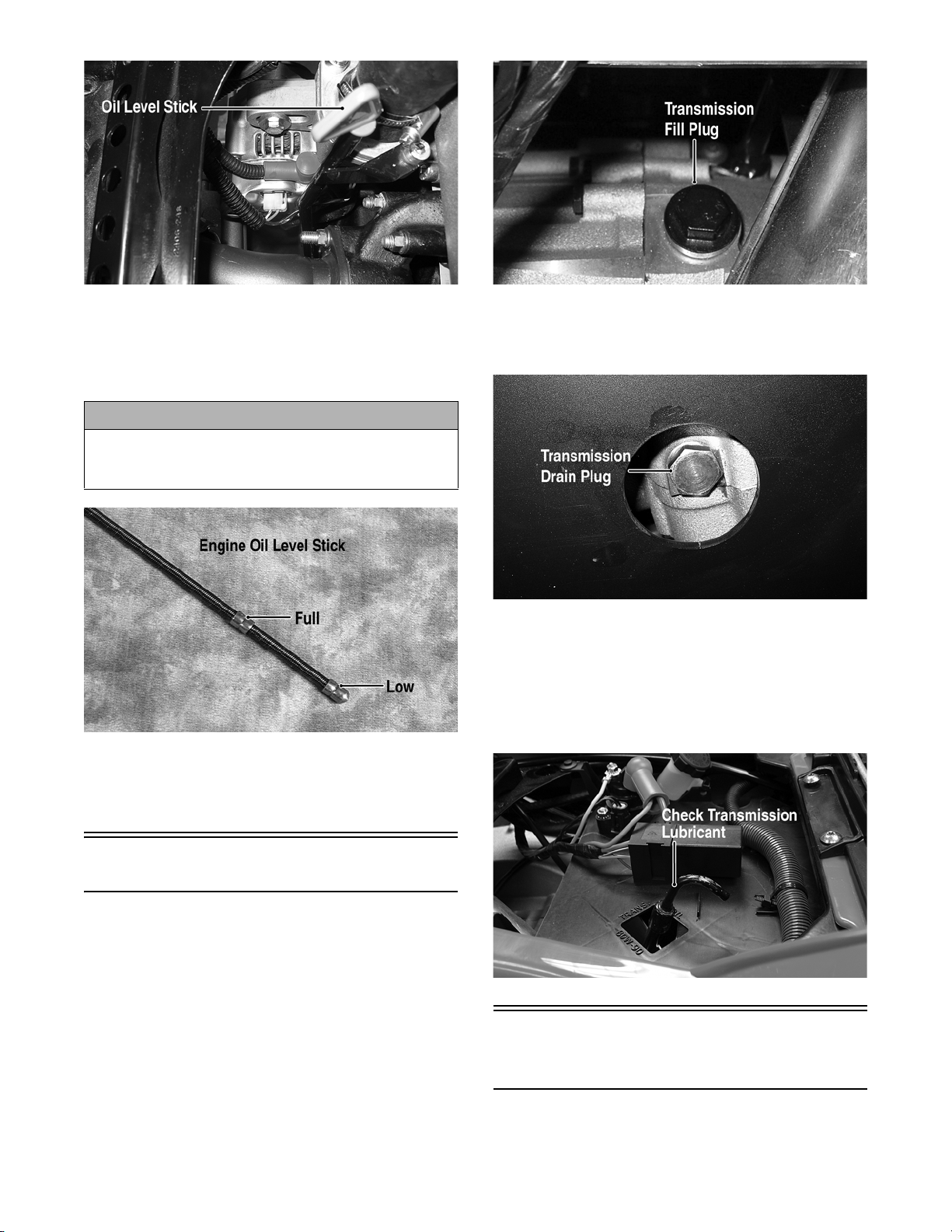
10. Remove the oil level stick and wipe it with a clean
cloth.
9
For Discount Arctic Cat Parts Call 606-678-9623 or 606-561-4983
DE519D
11. Install the oil level stick and push in firmly.
12. Remove the oil level stick; the engine oil level
should be above the illustrated “L” mark but not
higher than the illustrated “F” mark.
CAUTION
Do not over-fill the engine with oil. Always make
sure that the oil level is above the
higher than the
“F” mark.
13. Inspect the area around the drain plug and oil filter
for leaks.
“L” mark but not
DE024A
DE026A
3. Remove the transmission drain plug from the bottom of the transmission and drain the lubricant
into a drain pan.
DE016A
4. Install the drain plug and tighten securely. Pour
recommended lubricant into the filler hole. Install
the filler plug.
5. Remove the transmission lubricant level stick and
wipe it with a clean cloth; then check the lubricant
level with the level stick.
14. Install the right-side engine cover.
Transmission Lubricant
Check and change the transmission lubricant according to the Maintenance Schedule. When adding or
changing the lubricant, use approved SAE 80W-90
hypoid and use the following procedure.
1. Place the ATV on level ground.
2. Remove the transmission fill plug. Make sure not
to allow contaminants to enter the opening.
www.mymowerparts.com
10
DE002A
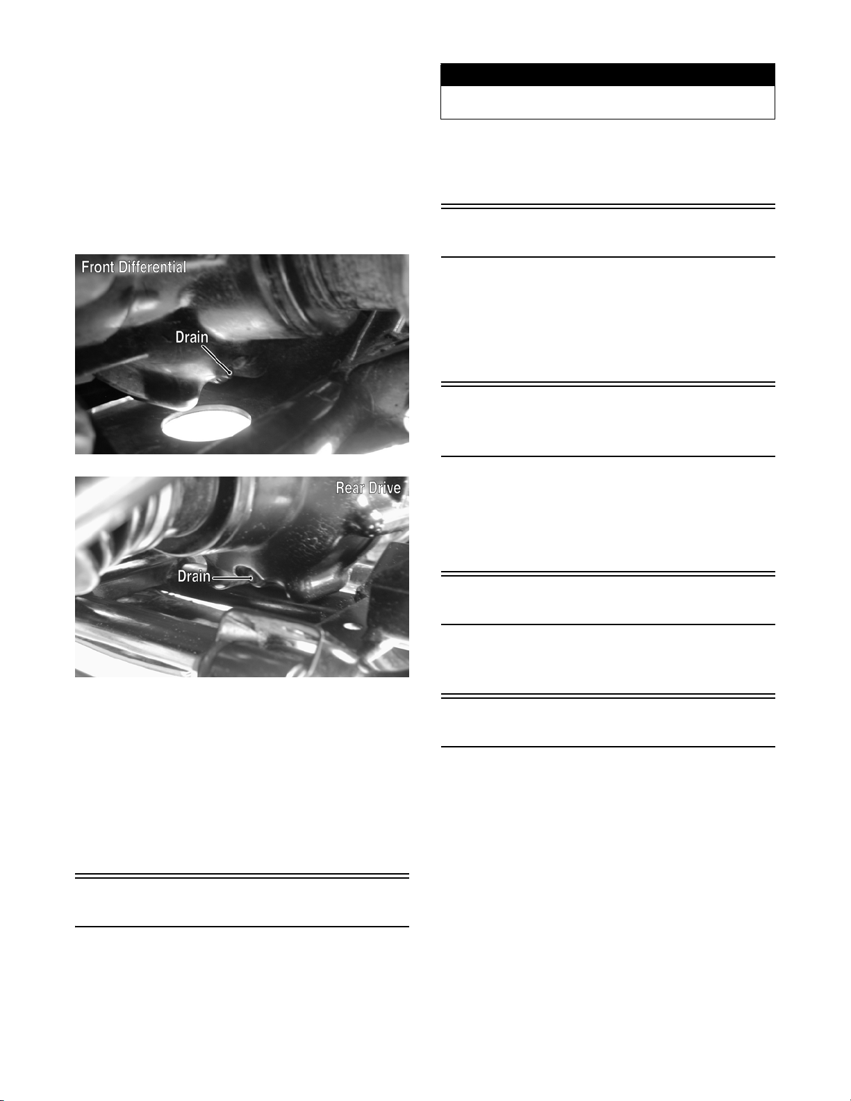
Front Differential/Rear
Drive Lubricant
Check and change the lubricant according to the Periodic
Maintenance Chart. When adding or changing the lubricant, use approved SAE 80W-90 hypoid gear lube.
For Discount Arctic Cat Parts Call 606-678-9623 or 606-561-4983
To check lubricant, remove each filler plug; the lubricant level should be 1 in. below the threads of the plug.
If low, add SAE approved 80W-90 hypoid gear lube as
necessary.
To change the lubricant, use the following procedure.
1. Place the ATV on level ground.
2. Remove each filler plug.
3. Drain the lubricant into a drain pan by removing in
turn the drain plug from each.
CF107B
! WARNING
Always use the size and type of tires specified.
Always maintain proper tire inflation pressure.
TIRE INFLATION PRESSURE
Front and rear tire inflation pressure should be 0.35
kg-cm² (5.0 psi).
Driveshaft/Coupling
The following drive system components should be
inspected periodically to ensure proper operation.
A. Spline lateral movement (slop).
B. Coupling cracked, damaged, or worn.
Nuts/Cap Screws/
Screws/Bolts
CF106C
4. After all the lubricant has been drained, install the
drain plugs and tighten to 42 in.-lb.
5. Pour the appropriate amount of recommended
lubricant into each filler hole.
6. Install the fill plugs. Tighten to 16 ft-lb.
NOTE: If the differential/rear drive lubricant is
contaminated with water, inspect the drain plug
and filler plug.
Tighten all nuts, cap screws, screws, and bolts. Make
sure rivets holding components together are tight.
Replace all loose rivets. Care must be taken that all
calibrated nuts, cap screws, screws, and bolts are tightened to specifications.
Injector Timing
To check/adjust injector timing, see Top-Side Components in Engine/Transmission.
Lights
Each time the ATV is used, lights should be checked
for proper function. Rotate the ignition switch to the
lights position; the headlights and taillight should illuminate. Test the brakelight by compressing the brake
lever. The brakelight should illuminate.
HEADLIGHT
Tires
TIRE SIZES
The ATV is equipped with low-pressure tubeless tires of
the size and type listed in General Specifications. Do not
under any circumstances substitute tires of a different
type or size.
www.mymowerparts.com
NOTE: The bulb portion of the headlight is fragile. HANDLE WITH CARE. When replacing the
headlight bulb, do not touch the glass portion of
the bulb. If the glass is touched, it must be cleaned
with a dry cloth before installing. Skin oil residue
on the bulb will shorten the life of the bulb.
11
For Discount Arctic Cat Parts Call 606-678-9623 or 606-561-4983
! WARNING
Do not attempt to remove the bulb when it is hot.
Severe burns may result.
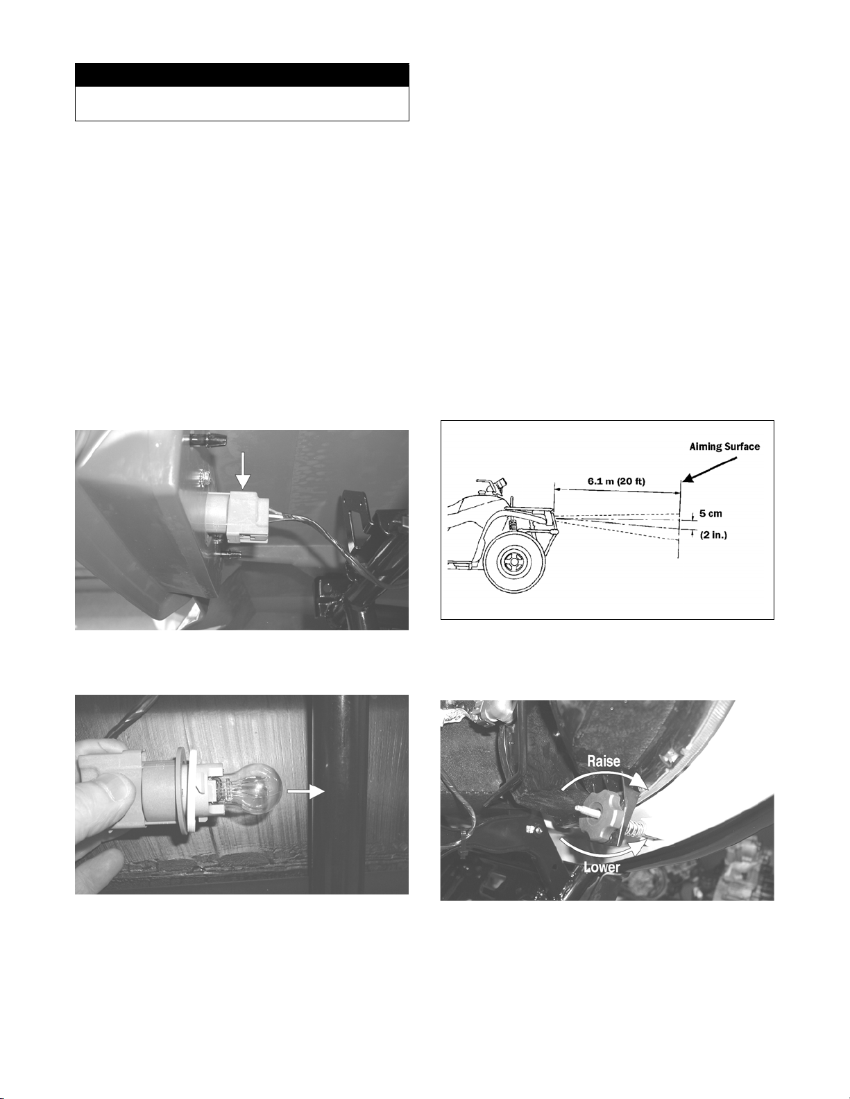
To replace the headlight bulb, use the following procedure.
1. Position the ATV on a level floor so the headlights
are approximately 6.1 m (20 ft) from an aiming
surface (wall or similar aiming surface).
NOTE: There should be an average operating
load on the ATV when adjusting the headlight aim.
1. Remove the wiring harness connector from the
back of the headlight.
2. Grasp the bulb housing, turn it counterclockwise,
and remove the bulb.
3. Install the new bulb into the housing and rotate it
completely clockwise.
4. Install the wiring harness connector.
TAILLIGHT-BRAKELIGHT
To replace the taillight-brakelight bulb, use the following procedure.
1. Turn the bulb socket counterclockwise and remove
from the housing.
2. Measure the distance from the floor to the midpoint of each headlight.
3. Using the measurements obtained in step 2, make
horizontal marks on the aiming surface.
4. Make vertical marks which intersect the horizontal
marks on the aiming surface directly in front of the
headlights.
5. Switch on the lights. Make sure the HIGH beam is
on. DO NOT USE LOW BEAM.
6. Observe each headlight beam aim. Proper aim is
when the most intense beam is centered on the vertical mark 5 cm (2 in.) below the horizontal mark
on the aiming surface.
CF135A
2. Pull the bulb straight out of the socket; then insert
a new bulb.
CF132A
3. Insert the socket into the housing and turn it clockwise to secure.
CHECKING/ADJUSTING HEADLIGHT AIM
The headlights can be adjusted vertically and horizontally. The geometric center of the HIGH beam light
zone is to be used for vertical and horizontal aiming.
www.mymowerparts.com
ATV-0070C
7. Adjust each headlight by turning the adjuster knob
clockwise to raise the beam or counterclockwise to
lower the beam.
CD714A
12
For Discount Arctic Cat Parts Call 606-678-9623 or 606-561-4983
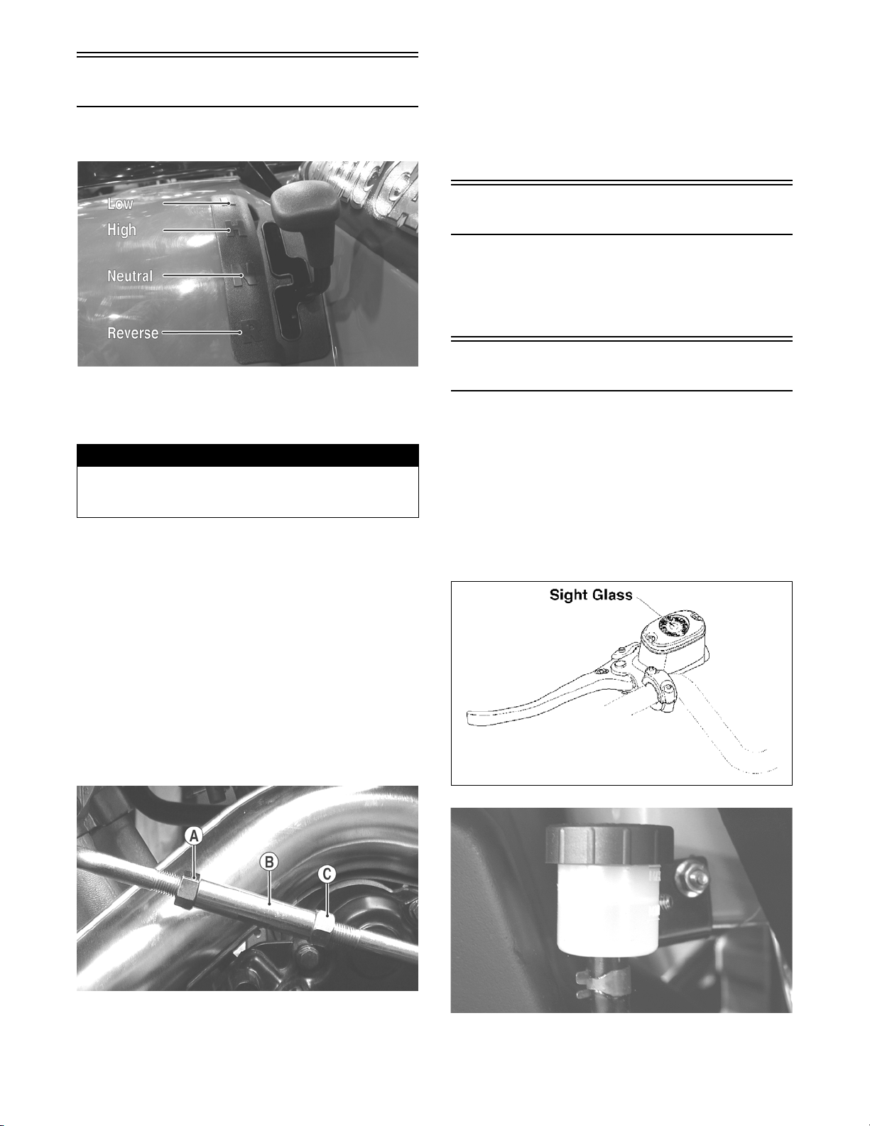
Shift Lever
CHECKING ADJUSTMENT
NOTE: An E (Error) in the gear position icon indicates no signal or a poor ground wire connection
in the circuit. Troubleshoot the harness connectors, gear shift position connector, gear shift position switch, and LCD connector.
4. Install the seat and left-side engine cover.
Frame/Welds/Racks
The frame, welds, and racks should be checked periodically for damage, bends, cracks, deterioration, broken
components, and missing components. If replacement
or repair constitutes removal, see Steering/Frame.
CF130B
Stop the ATV completely and shift the transmission
into the R position. The reverse gear indicator light
should be illuminated.
! WARNING
Never shift the ATV into reverse gear when the ATV is
moving as it could cause the ATV to stop suddenly
throwing the operator from the ATV.
If the reverse light does not illuminate when shifted to
the reverse position, the switch may be faulty, the fuse
may be blown, the bulb may be faulty, a connection
may be loose or corroded, or the lever may need
adjusting. To adjust, proceed to Adjusting Shift Lever.
ADJUSTING SHIFT LEVER
1. Place the shift lever in the R position; then remove
the seat and left-side engine cover.
2. With the ignition switch in the ON position, loosen
jam nut (A) (left-hand threads); then loosen jam
nut (C) and with the shift lever in the reverse position, adjust the coupler (B) until the transmission
is in reverse and the (R) icon appears on the LCD.
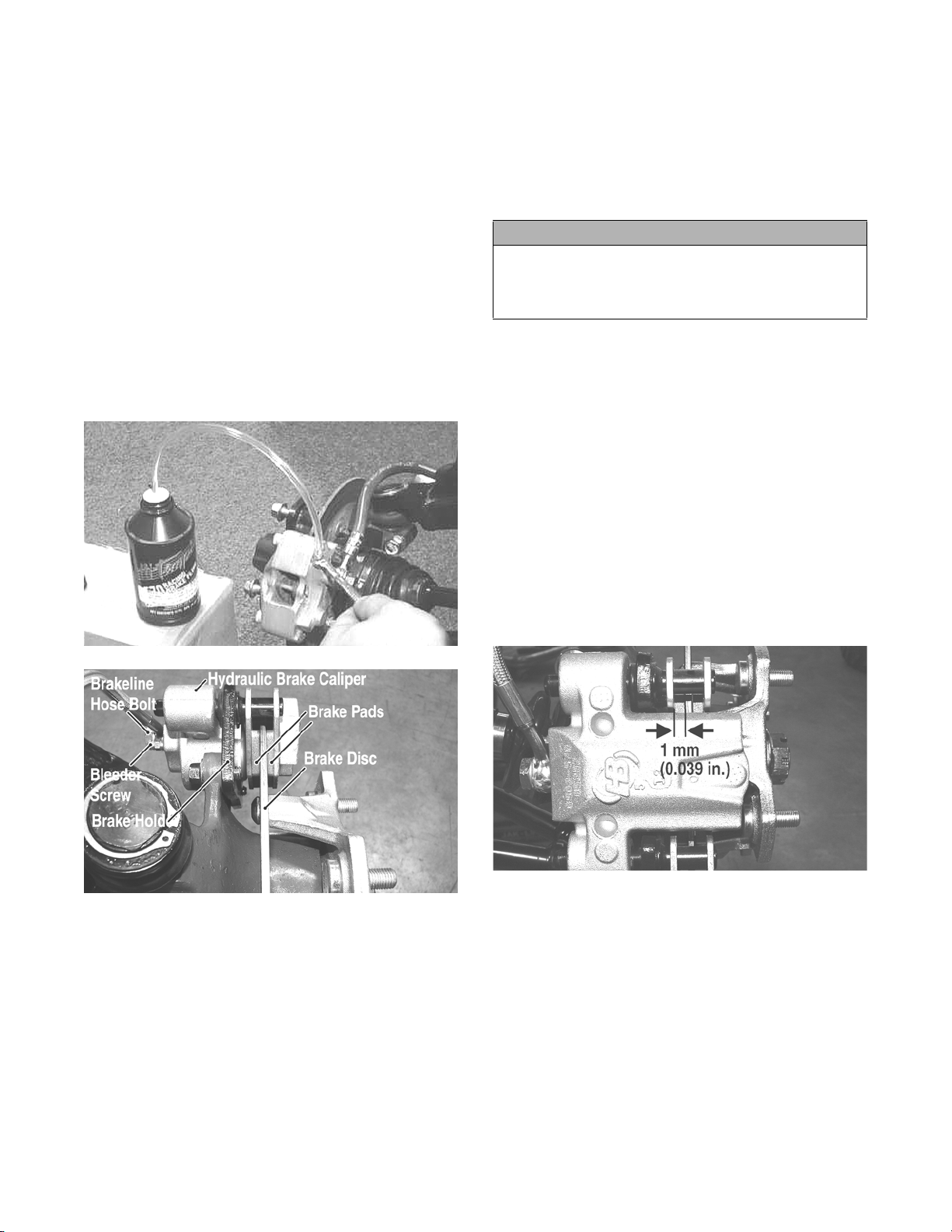
Hydraulic Brake Systems
CHECKING/BLEEDING
The hydraulic brake systems have been filled and bled
at the factory. To check and/or bleed a hydraulic brake
system, use the following procedure.
1. With the master cylinder in a level position, check
the fluid level in the reservoir. If the level in the
reservoir is not visible in the sight glass, add DOT
4 brake fluid.
CF258A
3. Tighten the jam nuts securely; then shift the transmission to each position and verify correct adjustment.
www.mymowerparts.com
738-420A
AL681
13
For Discount Arctic Cat Parts Call 606-678-9623 or 606-561-4983
2. Compress the brake lever/pedal several times to
check for a firm brake. If the brake is not firm, the
system must be bled.
3. To bleed the brake system, use the following procedure.
A. Remove the cover and fill the reservoir with
DOT 4 Brake Fluid.
B. Install and secure the cover; then slowly com-
press the brake lever several times.
C. Remove the protective cap, install one end of a
clear hose onto one FRONT bleeder screw, and
direct the other end into a container; then while
holding slight pressure on the brake lever, open
the bleeder screw and watch for air bubbles.
Close the bleeder screw before releasing the
brake lever. Repeat this procedure until no air
bubbles are present.
E. At this point, perform step B, C, and D on the
other FRONT bleeder screw; then move to the
REAR bleeder screw and follow the same procedure.
4. Carefully check the entire hydraulic brake system
that all hose connections are tight, the bleed
screws are tight, the protective caps are installed,
and no leakage is present.
CAUTION
This hydraulic brake system is designed to use DOT
4 brake fluid only. If brake fluid must be added, care
must be taken as brake fluid is very corrosive to
painted surfaces.
INSPECTING HOSES
Carefully inspect the hydraulic brake hoses for cracks
or other damage. If found, the brake hoses must be
replaced.
CHECKING/REPLACING PADS
The clearance between the brake pads and brake discs
is adjusted automatically as the brake pads wear. The
only maintenance that is required is replacement of the
brake pads when they show excessive wear. Check the
thickness of each of the brake pads as follows.
1. Remove a front wheel.
AF637D
PR377A
NOTE: During the bleeding procedure, watch the
reservoir sight glass very closely to make sure
there is always a sufficient amount of brake fluid.
When the sight glass changes from dark to light,
refill the reservoir before the bleeding procedure is
continued. Failure to maintain a sufficient amount
of fluid in the reservoir will result in air in the system.
2. Measure the thickness of each brake pad.
3. If thickness of either brake pad is less than 1.0 mm
(0.039 in.), the brake pads must be replaced.
PR376B
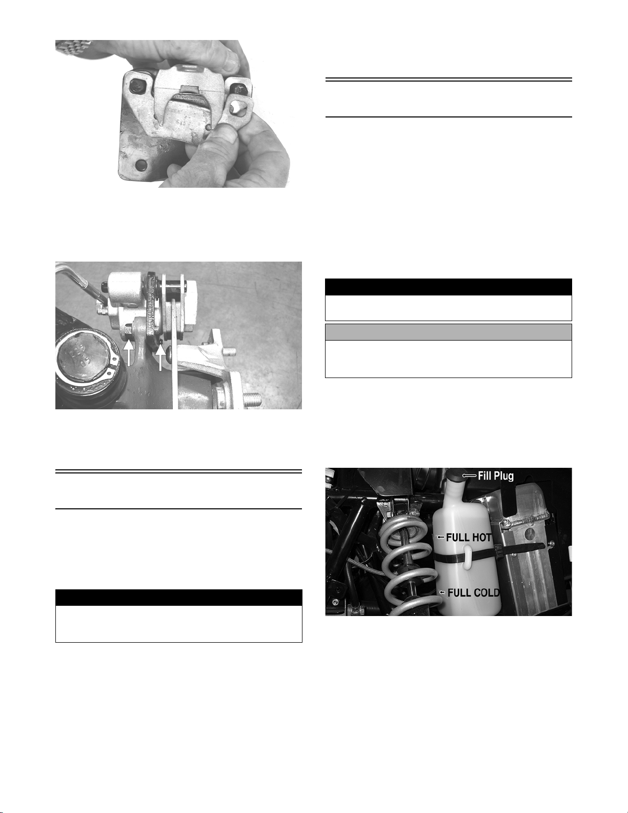
NOTE: The brake pads should be replaced as a set.
4. To replace the brake pads, use the following procedure.
A. Remove the wheel.
B. Remove the cap screws securing the caliper
holder to the knuckle; then remove the pads.
D. Repeat step C until the brake lever is firm.
14
www.mymowerparts.com
For Discount Arctic Cat Parts Call 606-678-9623 or 606-561-4983
PR237
C. Install the new brake pads.
D. Secure the caliper holder to the knuckle and/or
axle housing with the cap screws. Tighten to 20
ft-lb.
5. Verify that the brakelight illuminates when the
hand lever is compressed or the brake pedal is
depressed.
Coolant
When filling the cooling system, use a coolant/water
mixture which will satisfy the coldest anticipated
weather conditions of the area in accordance with the
coolant manufacturer’s recommendations. While the
cooling system is being filled, air may become trapped;
therefore, elevate the rear of the ATV 30-40 cm (12-16
in.) to allow air to bleed from the filler neck. Run the
engine for several minutes; then shut off the engine and
fill with coolant to the top of the filler neck.
NOTE: Use a good quality, biodegradable glycolbased, automotive-type antifreeze.
! WARNING
Never check the coolant level when the engine is hot
or the cooling system is under pressure.
PR377B
E. Install the wheel. Tighten to 45 ft-lb.
5. Burnish the brake pads (see Burnishing Brake
Pads).
Burnishing Brake Pads
Brake pads (both hydraulic and auxiliary) must be burnished to achieve full braking effectiveness. Braking
distance will be extended until brake pads are properly
burnished. To properly burnish the brake pads, use the
following procedure.
! WARNING
Failure to properly burnish the brake pads could lead
to premature brake pad wear or brake loss. Brake
loss can result in severe injury.
1. Choose an area large enough to safely accelerate
the ATV to 30 mph and to brake to a stop.
2. Accelerate to 30 mph; then compress brake lever or
apply the auxiliary brake to decelerate to 0-5 mph.
3. Repeat procedure on each brake system 20 times
until brake pads are burnished.
4. Adjust the auxiliary brake (if necessary).
CAUTION
After operating the ATV for the initial 5-10 minutes,
stop the engine, allow the engine to cool down, and
check the coolant level. Add coolant as necessary.
To check/add coolant, use the following procedure.
1. Check the level of coolant in the coolant expansion tank located under the right front fender. The
coolant level should be between the Full Cold and
Full Hot lines.
DE019A
2. Remove the rubber plug from the neck of the coolant expansion tank and add coolant as necessary;
then install the plug.
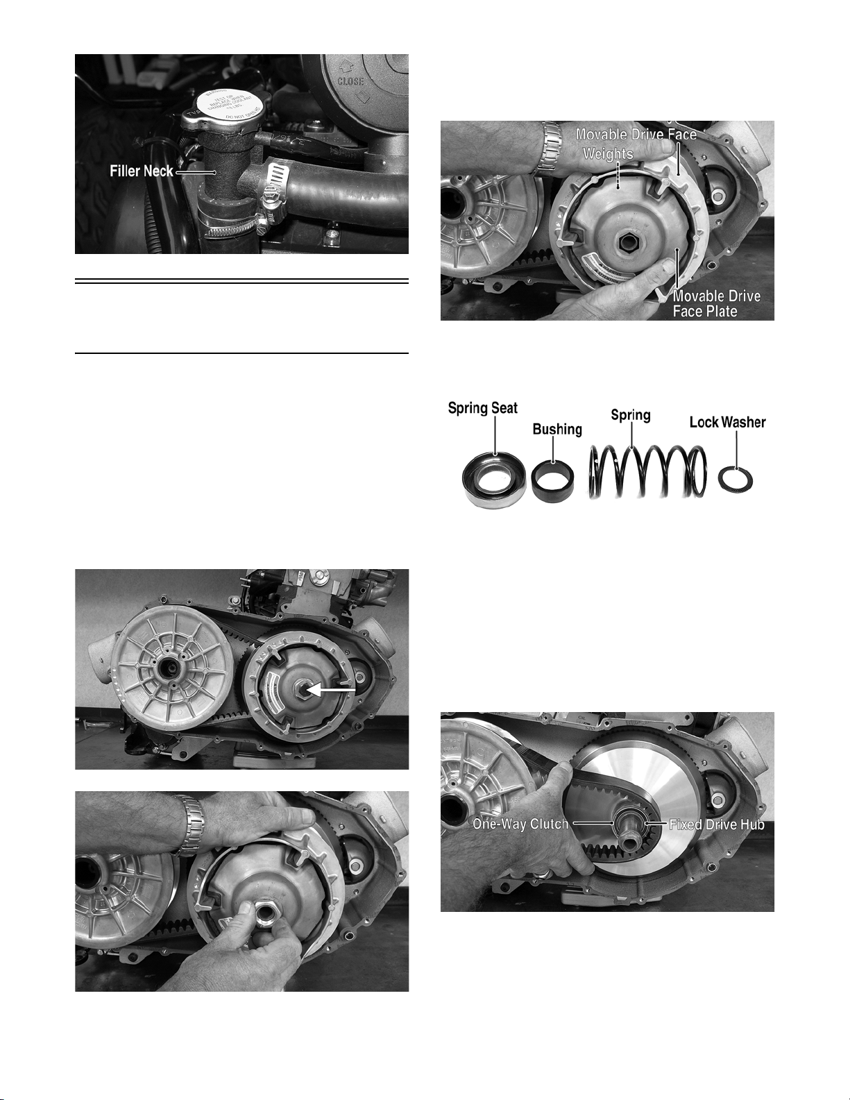
3. Remove the filler cap located under the service
access cover and add coolant as necessary to bring
coolant level to the top of the filler neck. Install
and tighten the filler cap.
www.mymowerparts.com
15
For Discount Arctic Cat Parts Call 606-678-9623 or 606-561-4983
4. Remove the movable drive face using care to keep
the face plate tight against the drive face to prevent
the weights from falling out. Account for a spring
seat, spring, bushing, and lock washer.
DE073A
Checking/Replacing
V-Belt
REMOVING
1. Remove the right-side footrest (see Steering/
Frame).
2. Remove the cap screws securing the V-belt cover;
then using a rubber mallet, gently tap on the cover
tabs to loosen the cover. Remove the cover.
3. Remove the cap screw securing the drive clutch to
the flywheel stub axle; then remove the nut and
lock washer securing the movable drive face to the
fixed drive hub.
DE096A
DE094A
5. Thread one of the V-belt cover screws into the
fixed driven face and turn clockwise to open the
driven pulley faces.
6. Push the V-belt down between the sheaves of the
driven pulley approximately one inch; then making sure not to dislocate the one-way clutch from
the fixed drive hub, squeeze the belt together and
remove from the drive clutch.
16
DE093A
INSTALLING
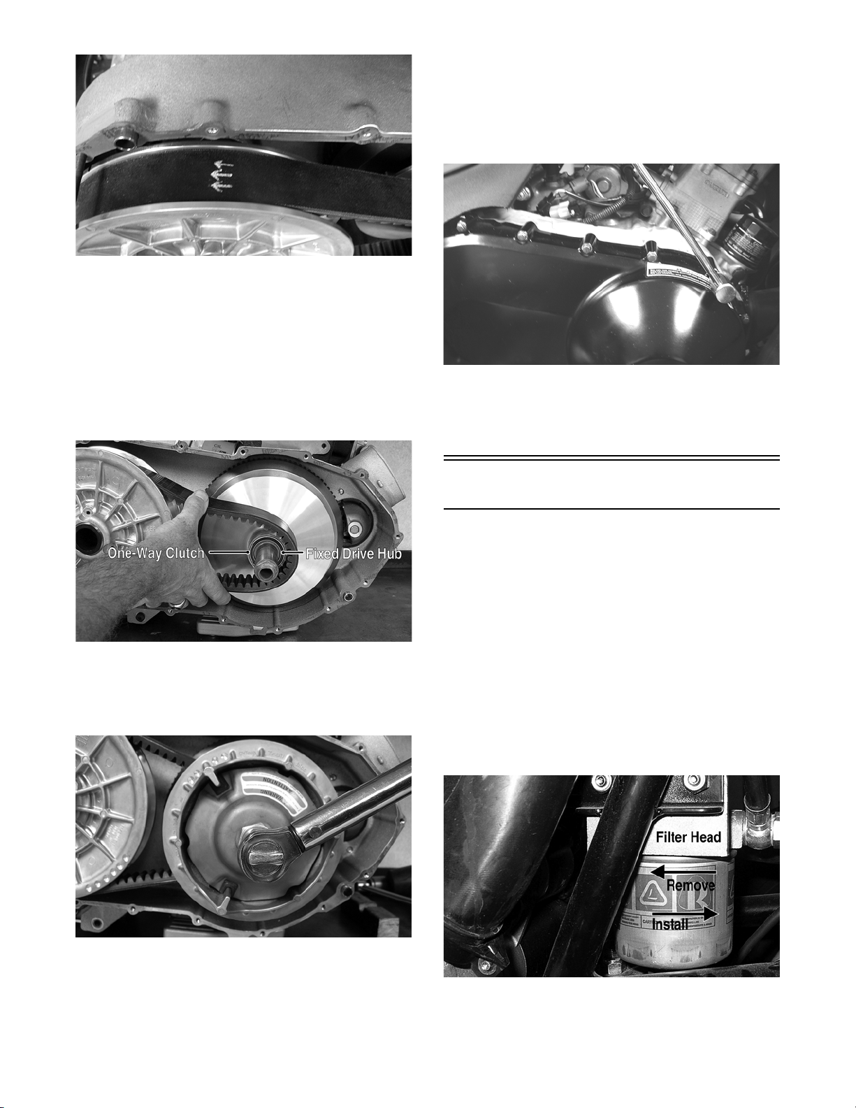
1. Place the V-belt into position over the driven pul-
DE095
ley noting the directional arrows on the V-belt.
www.mymowerparts.com
DE098A
For Discount Arctic Cat Parts Call 606-678-9623 or 606-561-4983
DE488
NOTE: The diesel engine in this ATV rotates
counterclockwise as viewed from the right side;
therefore, if directional arrows are printed on the Vbelt, they must be directed rearward.
5. Install the cap screw securing the drive clutch
assembly to the flywheel/PTO shaft and tighten to
40 ft-lb.
6. Place the V-belt cover gasket into position; then
install the cover and secure with the cap screws.
Tighten to 9 ft-lb.
2. Push the V-belt down into the driven pulley
approximately one inch; then squeeze the belt
together and slide over the fixed drive hub and
onto the one-way clutch.
DE098A
3. Pinch the V-belt together near its center and slide
the movable drive face onto the drive hub. Secure
the drive face with a nut (threads coated with red
Loctite #271). Tighten the nut to 85 ft-lb.
CD083
7. Secure the front fender to the footrest with the two
cap screws. Tighten securely.
8. Install the right-side footrest (see Steering/Frame).
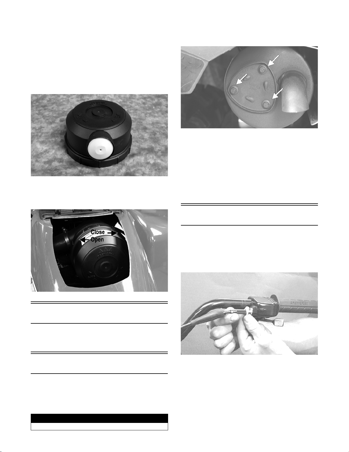
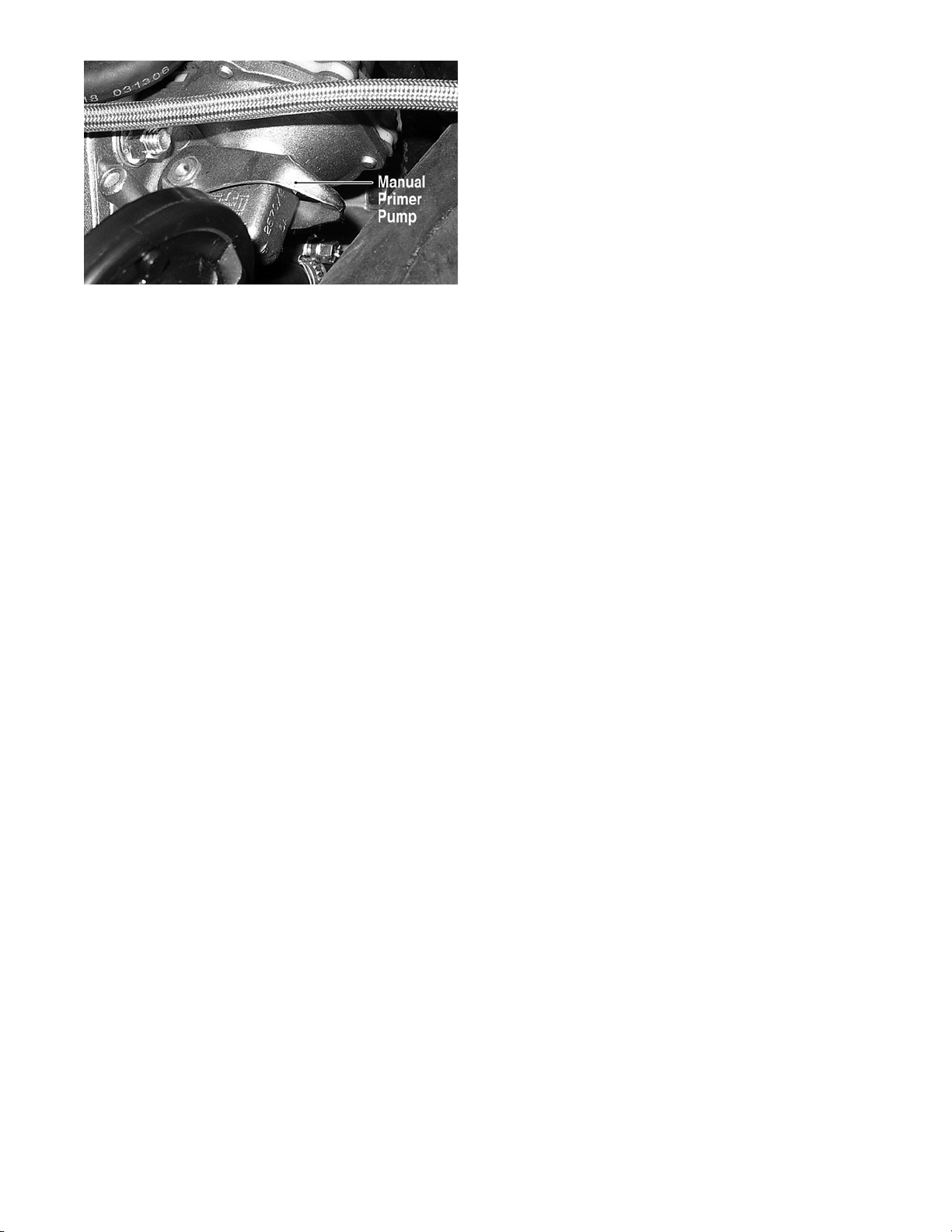
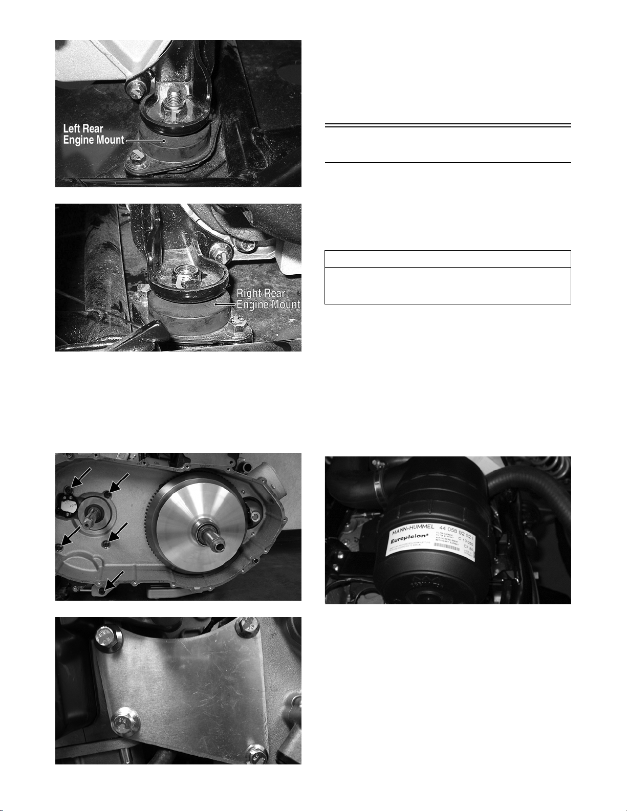
Fuel Filter
This diesel-powered ATV is equipped with a high efficiency fuel filter. The fuel filter should be changed in
accordance with the maintenance schedule or more
often if operated under severe conditions or winter
operation. To change the fuel filter, use the following
procedure.
1. Remove the right front fender splash panel; then
using an appropriate filter wrench, remove the fuel
filter.
2. Apply a light coat of oil to the seal ring of the new
fuel filter; then install the filter. Tighten until the
seal ring contacts the filter head; then tighten an
additional 3/4 turn.
DE483
NOTE: At this point, the cap screw can be
removed from the fixed driven face.
4. Rotate the V-belt and pulley until the V-belt is
flush with the top of the driven pulley.
www.mymowerparts.com
DE032D
3. Depress and release the manual primer pump to
charge the fuel filter and purge any air from the
system.
17
For Discount Arctic Cat Parts Call 606-678-9623 or 606-561-4983
NOTE: Cycle the manual primer pump until the lever
becomes firm and resistance is observed. The system will bleed itself through the tank return circuit.
4. Check for any fuel leaks; then start the engine and
check for normal engine operation.
DE031A
18
www.mymowerparts.com
For Discount Arctic Cat Parts Call 606-678-9623 or 606-561-4983
Engine/Transmission
This section has been organized into sub-sections
which show a progression for the complete servicing
of the Arctic Cat ATV engine/transmission.
To service the crankcase, the engine must be removed
from the frame.
To service top-side, left-side, and right-side components (except cylinder head), the engine does not have
to be removed from the frame.
NOTE: Arctic Cat recommends the use of new
gaskets, lock nuts, and seals and lubricating all
internal components when servicing the engine/
transmission.
NOTE: Some photographs and illustrations used
in this section are used for clarity purposes only
and are not designed to depict actual conditions.
SPECIAL TOOLS
A number of special tools must be available to the
technician when servicing the engine/transmission.
Description p/n
Torx-Head Screwdriver - #30 0644-344
Drive Clutch Removal Tool 0444-226
Fuel Injector Timing Tool 0444-234
Timing Belt Tensioning Tool 0444-231
Main Bearing Seal Installation Tool 0444-233
Unit Injector Retainer Nut Tool 0444-227
Pre-Combustion Chamber Ring Nut Tool 0444-235
Pre-Combustion Chamber Removal Tool 0444-228
Pre-Combustion Chamber Index Tool 0444-229
Valve Seal Installation Tool 0444-230
NOTE: Special tools are available from the Arctic
Cat Service Parts Department.
Specifications
VALVES AND GUIDES
Valve Face Diameter (intake)
Valve Clearance (intake/exhaust)
(cold engine)
Valve Guide/Stem Clearance 0.015-0.060 mm
Valve Guide Inside Diameter 7.005-7.020 mm
Valve Stem Diameter 6.960-6.990 mm
Valve Face/Seat Width (intake/exhaust) 1.6-2.0 mm
Valve Spring Free Length (min) 43.0 mm (1.69 in.)
CAMSHAFT AND CYLINDER HEAD
Camshaft Lobe Height (min)
(intake/exhaust)
Camshaft Injection Lobe (min) 28.848 mm (1.136 in.)
Camshaft Journal Holder (max)
Inside Diameter
Camshaft Journal Diameter (min) 36.975 mm (1.456 in.)
Cylinder Head Distortion (max) 0.10 mm (0.004 in.)
Rocker Arm Bore 18.015-18.030 mm
Rocker Arm Shaft 17.989-18.000 mm
CYLINDER, PISTON, AND RINGS
Bore x Stroke 75 x 77.6 mm
Piston Ring End Gap - Installed (min) 0.25 mm (0.0098 in.)
Piston Ring Groove Width (1st)
Piston Pin Bore (max) 18.025 mm (0.7096 in.)
Piston Pin Outside Diameter (min) 17.996 mm (0.7085 in.)
Connecting Rod Piston Pin (max)
Bushing (inside diameter)
Crankshaft Main Bearing Journal 51.023-51.059 mm
Crankshaft Connecting Rod (min)
Journal
Connecting Rod Clearance 0.021-0.066 mm
Main Bearing Clearance 0.023-0.078 mm
Rod Bearing Diameter 40.021-40.050 mm
Oil Pump Pressure (min)
at 120° C (248° F)@900 RPM
Cooling Fan Thermo-Switch (offon)
Operating Temperature (onoff)
(exhaust)
CRANKSHAFT
34.4 mm (1.35 in.)
30.2 mm (1.19 in.)
0.20 mm (0.008 in.)
(0.0006-0.0024 in.)
(0.2758-0.2764 in.)
(0.2740-0.2752 in.)
(0.063-0.079 in.)
29.498 mm (1.161 in.)
37.060 mm (1.459 in.)
(0.7092-0.7098 in.)
(0.7082-0.7087 in.)
(2.95 x 3.05 in.)
0.090-0.125 mm
(0.0035-0.0049 in.)
(2nd)
0.050-0.085 mm
(0.0020-0.0033 in.)
(3rd)
0.040-0.075 mm
(0.0016-0.0030 in.)
18.025 mm (0.7096 in.)
(2.009-2.010 in.)
39.9 mm (1.57 in.)
(0.0008-0.0026 in.)
(0.0009-0.0031 in.)
(1.5756-1.5767 in.)
1.1 kg/cm² (15.6 psi)
93° C (199° F)
87° C (189° F)
Specifications subject to change without notice.
www.mymowerparts.com
19
For Discount Arctic Cat Parts Call 606-678-9623 or 606-561-4983
Removing Engine/
Transmission
Many service procedures can be performed without
removing the engine/transmission from the frame.
Closely observe the note introducing each sub-section
for this important information.
AT THIS POINT
If the technician’s objective is to service/replace leftside components, right-side components, and/or
top-side components, the engine/transmission does
not have to be removed from the frame.
AT THIS POINT
If the technician’s objective is to service/replace the
transmission, the engine does not have to be
removed from the frame (proceed to Transmission in
this sub-section).
DE066A
ENGINE/TRANSMISSION
1. Remove the seat; then from the rear, remove the
battery cables (negative first) and the battery.
2. Remove the front rack, front body panel, and left
and right footrests (see Steering/Frame).
3. Drain the coolant, engine oil, and transmission
lubricant (see Periodic Maintenance/Tune-Up).
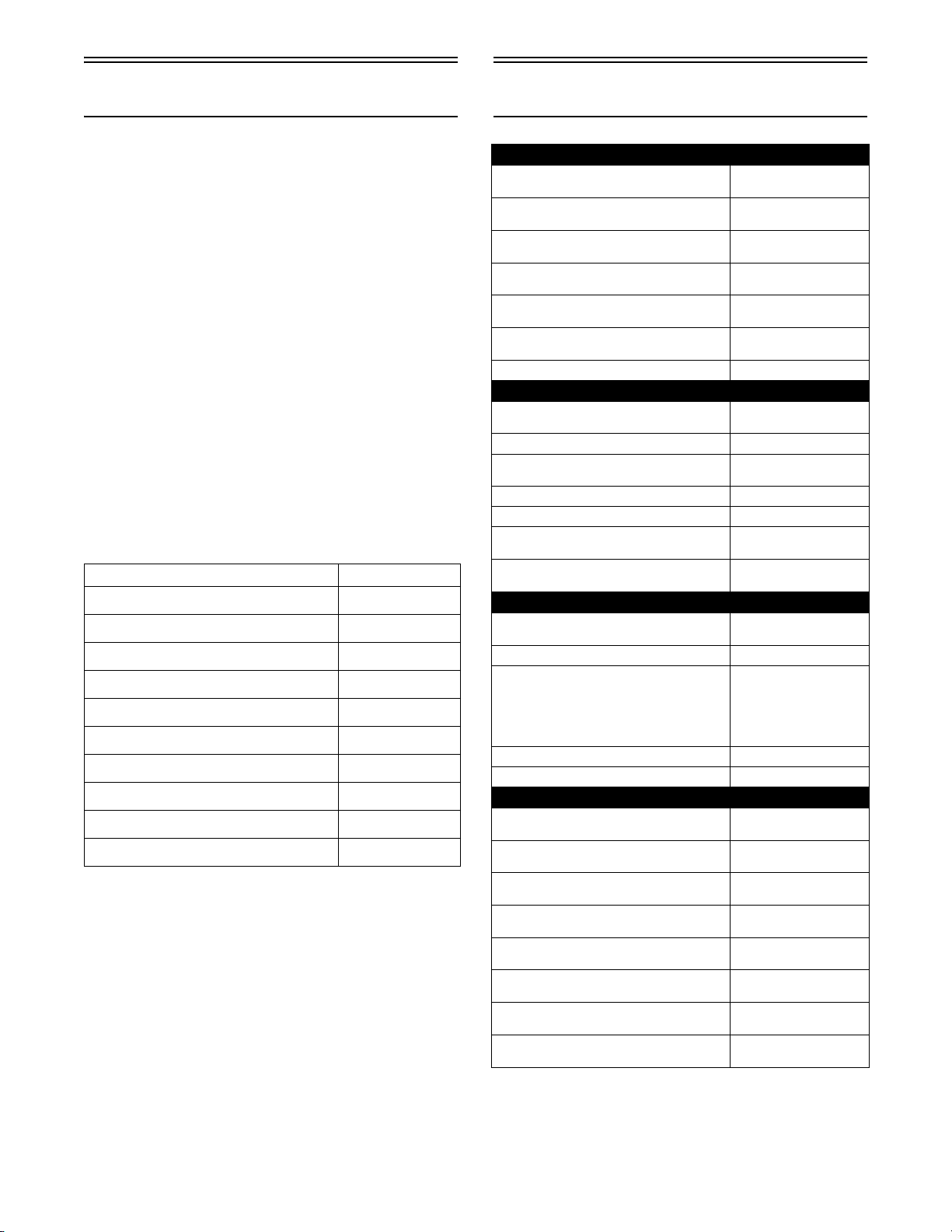
4. From the left side, remove the E-clip from the shift
arm; then disconnect the shift linkage from the
shift arm. Account for a bushing and washer.
DE071A
6. Loosen the two hose clamps securing the air
diverter to the inlet hoses; then remove the air
diverter.
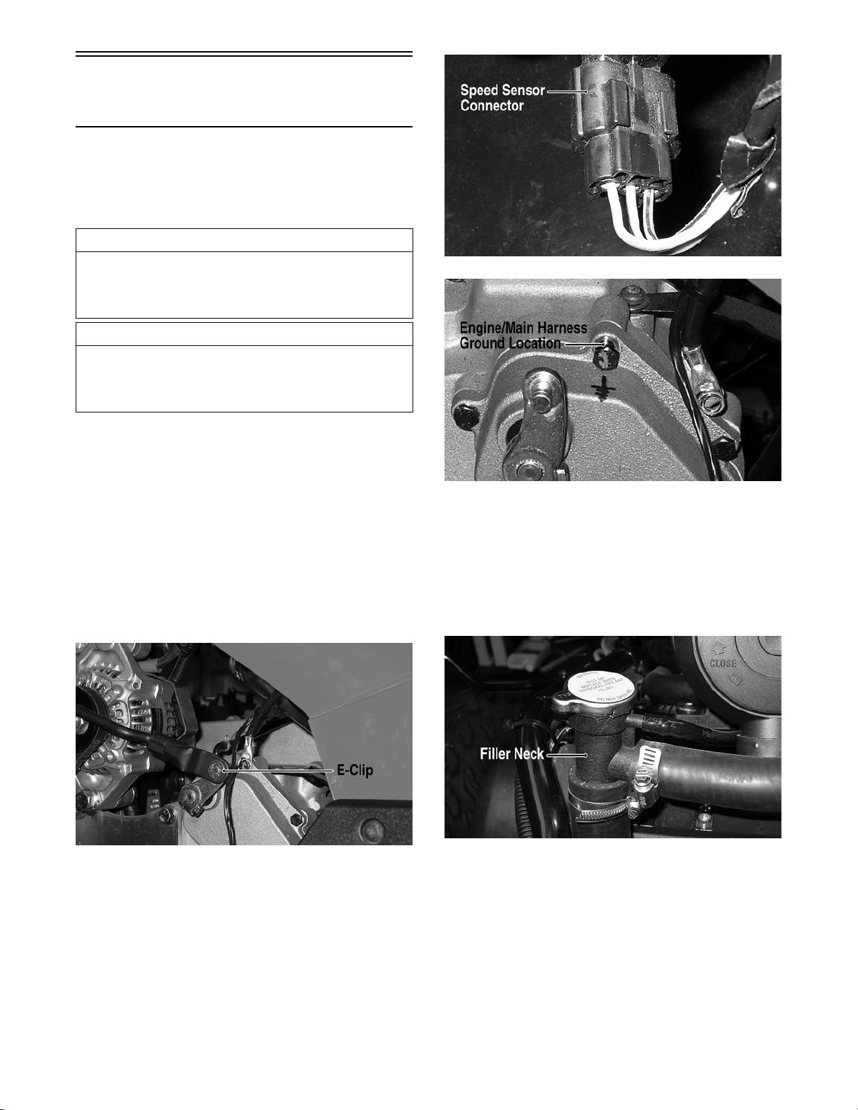
7. Remove the upper radiator hose from the filler
neck; then loosen the hose clamp securing the
filler neck to the thermostat housing and remove
the filler neck.
DE064A
5. Disconnect the speed sensor connector from the
speed sensor; then remove the cap screw securing
the engine and main harness ground to the transmission.
www.mymowerparts.com
20
DE073A
NOTE: Filler neck can remain attached to the
overflow recovery hose.
8. Remove the upper radiator hose from the radiator.
9. Remove the four cap screws securing the air filter
housing assembly to the frame; then disconnect
the air inlet hose from the intake manifold and
remove the air filter housing assembly.
For Discount Arctic Cat Parts Call 606-678-9623 or 606-561-4983
DE074A
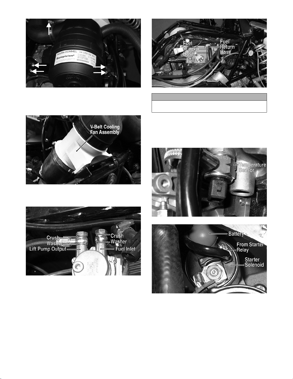
10. Remove the V-belt cooling fan assembly; then disconnect the V-belt inlet and outlet cooling boots
from the V-belt housing.
DE076A
11. Remove the fuel inlet and lift pump output hoses
from the lift pump. Discard four crush washers.
DE065A
CAUTION
The fuel rail connections are easily bent. Use care
when removing the hose clamps and hoses.
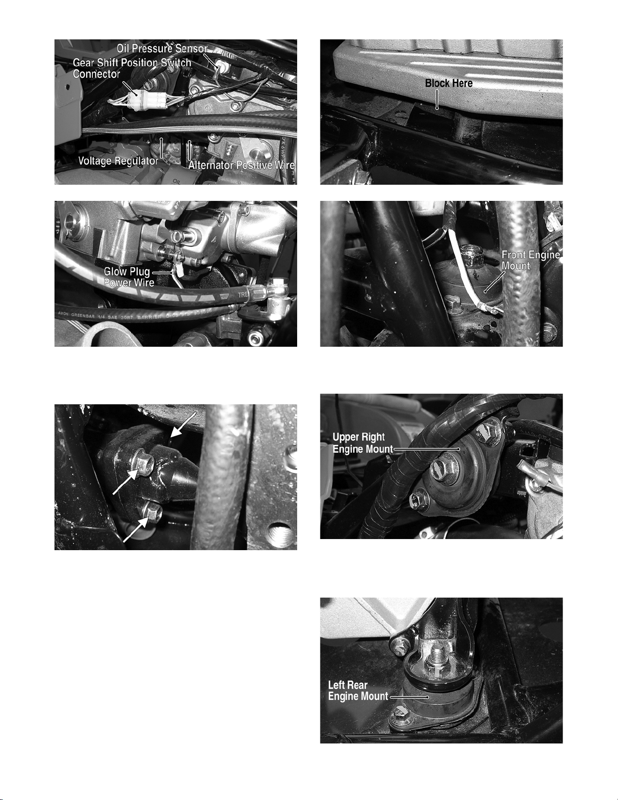
13. Disconnect the wire connectors from the temperature sensor, oil pressure sensor, gear shift position
switch connector, and voltage regulator; then disconnect the starter solenoid, glow plug power
wire, and the alternator positive wire.
DE104A
DE078A
12. Remove the fuel supply and fuel return hoses from
the fuel rail.
www.mymowerparts.com
DE067A
21
For Discount Arctic Cat Parts Call 606-678-9623 or 606-561-4983
DE077A
DE494A
14. Apply the hand brake and engage the brake lever
lock; then remove the cap screws from the front
drive coupler.
DE089A
DE086A
19. Remove the cap screw and nut from the upper
right engine mount. Account for a flat washer.
DE081A
15. Remove the cap screws from the rear drive coupler.
16. Remove the exhaust springs; then remove the muffler. Account for a grafoil seal.
17. Remove the nuts securing the exhaust pipe to the
exhaust manifold; then remove the exhaust pipe.
Account for a steel gasket.
18. Place a suitable block between the oil pan and
frame member; then remove the front engine
mount cap screw and nut. Account for a flat
washer.
www.mymowerparts.com
22
DE088A
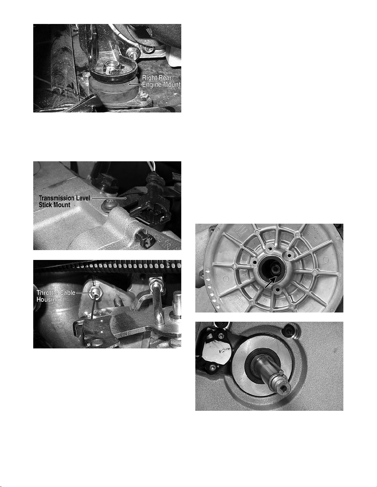
20. Remove the nuts and cap screws from the left rear
and right rear engine mounts. Account for two flat
washers.
DE085A
For Discount Arctic Cat Parts Call 606-678-9623 or 606-561-4983
DE090A
21. Remove the transmission level stick mount and
housing; then disconnect the throttle cable from
the throttle control arm and unthread the throttle
cable housing. Route the throttle cable away from
the engine.
TRANSMISSION
NOTE: The transmission can be removed for servicing without removing the engine. To remove the
transmission, use the following procedure.
1. Remove the inner front splash shields, foot pegs,
and forward footwells (see Steering/Frame).
2. Remove three cap screws securing the front propeller shaft to the front differential input coupler.
3. Remove four cap screws securing the rear propeller shaft to the output drive flange.
4. Remove the transmission level stick housing and
account for an O-ring.
5. Drain the transmission lubricant into a suitable
container; then disconnect the transmission vent
hose, gear shift position switch connector, speed
sensor connector, and shift linkage.
6. Remove the V-belt (see Periodic Maintenance/
Tune-Up).
DE091A
DE080A
22. Move the engine/transmission slightly forward
and shift the rear propeller shaft to the right; then
rotate the rear of the assembly out of the left side.
7. Remove the nut securing the driven pulley to the
transmission input shaft; then remove the driven
pulley. Account for a flat washer, square key, and
four shims.
DE106A
NOTE: The front engine mount bracket and fuel
filter housing can be removed to allow more clearance at the front of the engine.
23. Remove the front propeller shaft from the transmission output yoke; then slide the engine/transmission out the left side lifting the transmission to
tilt the engine sufficiently forward for the top of
the engine to clear the upper frame tubes.
24. Attach a suitable lift and lift the engine free of the
frame.
www.mymowerparts.com
DE108
8. Remove the nuts from the left rear and right rear
engine mount bolts; then remove the bolts.
Account for two flat washers.
23
For Discount Arctic Cat Parts Call 606-678-9623 or 606-561-4983
11. Slide the transmission to the left side until the rear
output flanges can be separated; then move the
transmission to the rear to expose the front output
yoke boot.
12. Slide the boot off the yoke and separate the front
propeller shaft from the front output drive yoke.
Top-Side Components
DE085A
DE090A
9. Block the rear of the engine up; then remove the
rear mounts from the transmission.
10. Remove five cap screws securing the transmission
to the V-belt housing; then remove four cap screws
securing the engine-to-transmission mounting
plate.
NOTE: For efficiency, it is preferable to remove
and disassemble only those components which
need to be addressed and to service only those
components. The technician should use discretion
and sound judgment.
AT THIS POINT
To service any one specific component, only limited
disassembly of components may be necessary. Note
the AT THIS POINT information in each sub-section.
NOTE: The engine/transmission does not have to
be removed from the frame for this procedure.
SPEED GOVERNOR
Removing/Disassembling
1. Remove the timing belt (see Left-Side Components in this section).
2. Remove the air filter assembly; then remove the
valve cover.
24
DE589A
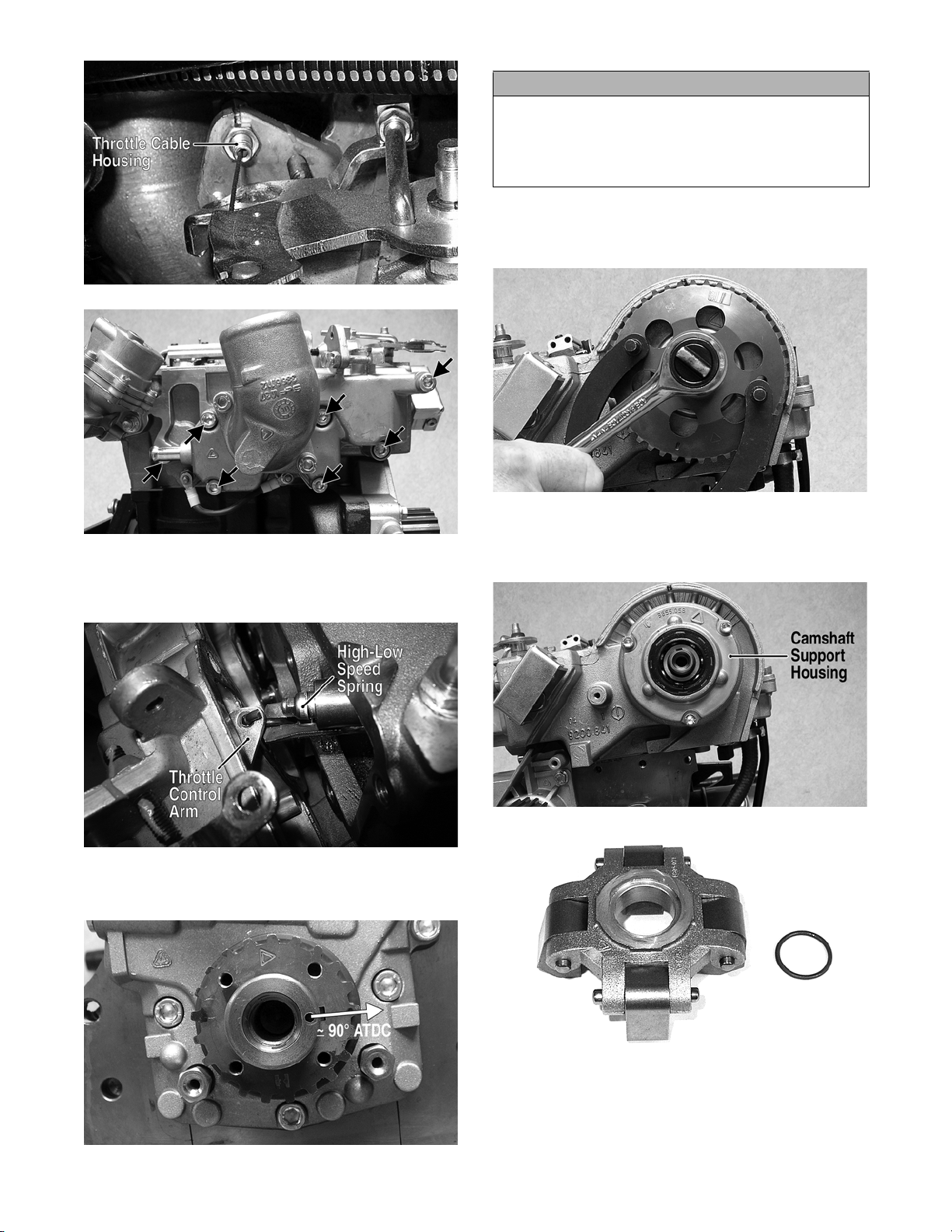
3. Disconnect the throttle cable; then remove the cap
screws securing the intake manifold/throttle cable
housing to the cylinder head.
www.mymowerparts.com
DE487
DE074
For Discount Arctic Cat Parts Call 606-678-9623 or 606-561-4983
CAUTION
Failure to rotate the engine away from TDC will leave
the flywheel-side piston in close proximity to the
valves. If the camshaft is rotated while attempting to
remove the camshaft drive pulley, severe valve damage WILL occur.
6. Using a suitable holding tool, remove the cap
screw securing the camshaft drive pulley; then
remove the pulley.
DE080A
DE248A
4. Disconnect the high-low speed spring assembly from
the throttle control arm; then remove the intake manifold/throttle control housing. Account for a gasket.
DE258A
5. Rotate the crankshaft in the direction of rotation
approximately 90° from TDC.
DE276
7. Remove the front camshaft support housing; then
remove the governor flyweight assembly. Account
for a small O-ring.
DE245A
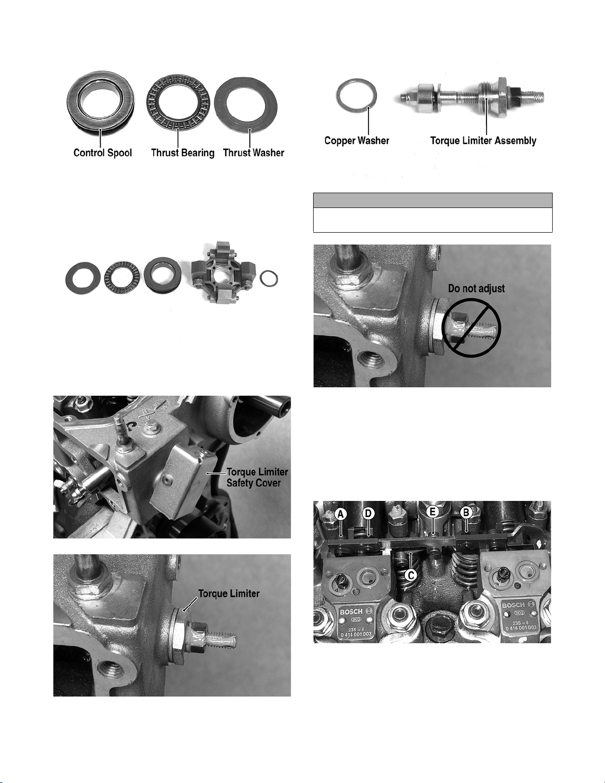
8. Remove the control spool, thrust bearing, and
thrust washer. Note the order of disassembly and
keep together and in order for assembling purposes.
DE275A
www.mymowerparts.com
DE277
25
For Discount Arctic Cat Parts Call 606-678-9623 or 606-561-4983
DE278A
DE279
9. Remove the torque limiter safety cover; then
remove the torque limiter assembly. Account for a
copper washer.
DE286A
CAUTION
Do not break the seal or turn the torque limiter
adjuster screw. Severe engine damage could occur.
DE285B
10. Remove the fuel injection control rack by removing screws (A) and (B) and spring (C); then
remove the governor fork pivot pin. Account for
an O-ring.
NOTE: Do not loosen or remove screws (D) or (E)
or fuel delivery equalization will have to be performed.
26
DE252A
DE291A
DE285A
www.mymowerparts.com
For Discount Arctic Cat Parts Call 606-678-9623 or 606-561-4983
DE327
DE282
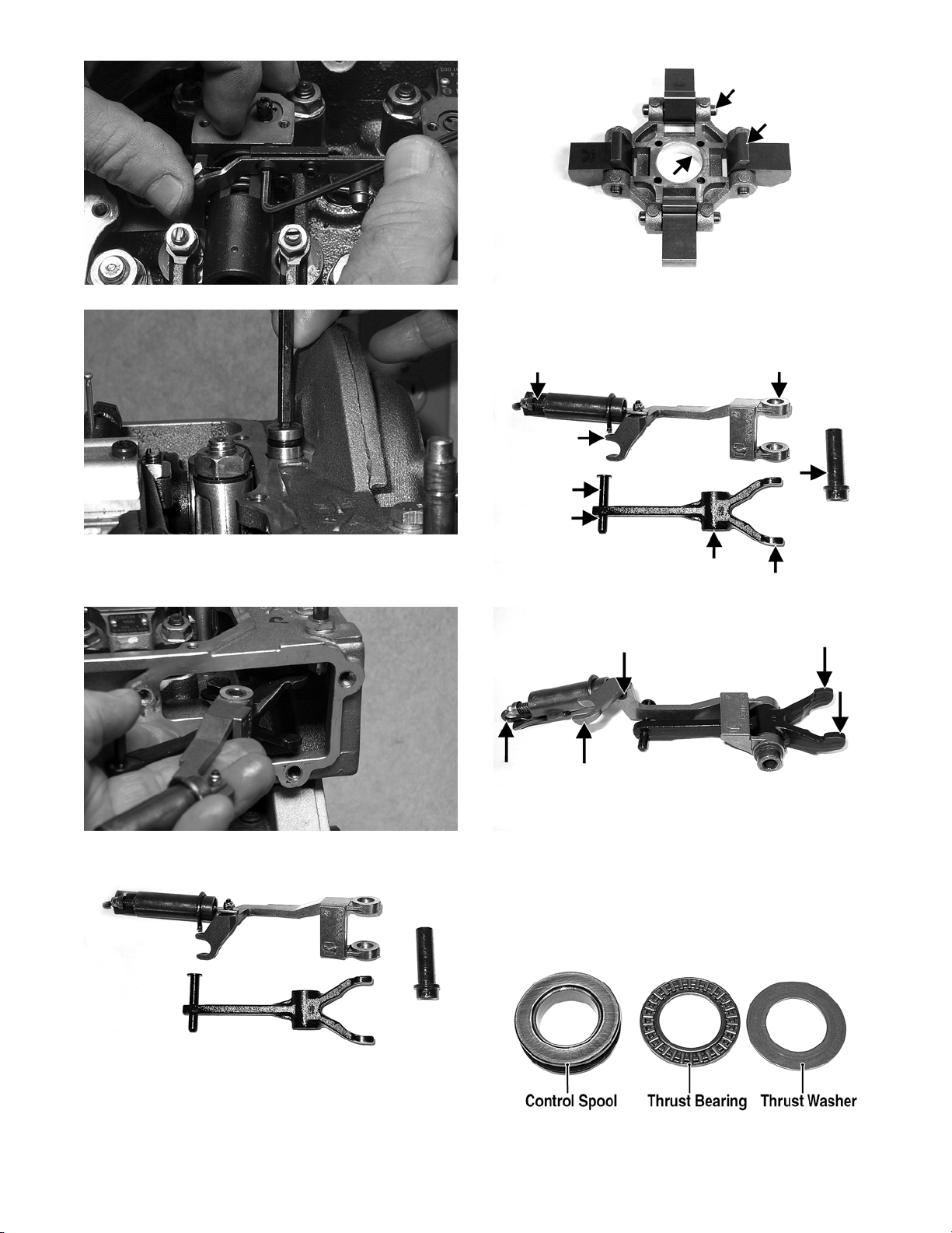
11. Remove the governor fork and governor spring
assembly through the opening on the linkage housing.
DE247A
2. Inspect all springs, links, and pivot pins for proper
tension, excessive wear, or loose fit.
DE254A
DE253
DE254
Inspecting
1. Inspect the flyweight assembly for loose pins,
worn contact points, or excessive pivot point wear.
www.mymowerparts.com
DE256A
3. Inspect the control spool, thrust bearing, and thrust
washer for scoring, excessive wear, or missing
bearing rollers.
DE278A
27
For Discount Arctic Cat Parts Call 606-678-9623 or 606-561-4983
4. Coat all serviceable parts with clean engine oil.
Assembling/Installing
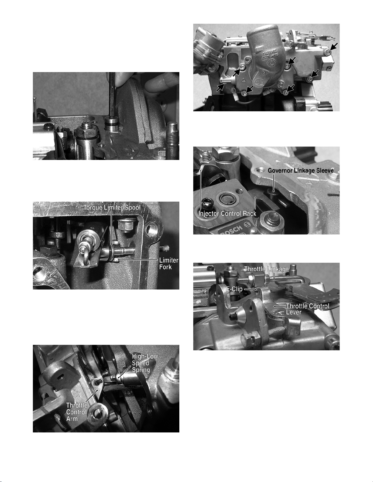
1. Install the governor fork assembly into the cylinder head and secure with the governor fork pivot
pin. Tighten securely.
DE282
2. Using a new copper washer, install the torque setting screw assembly and tighten securely; then
install the safety cover. Make sure the torque limiter spool engages the limiter fork.
DE248A
4. Install the fuel injector control rack making sure
the slotted end engages the governor linkage
sleeve; then tighten the cap screws to 11 in.-lb.
DE288A
3. Using a new gasket, install the intake manifold/
throttle control assembly by first connecting the
high/low speed spring assembly to the throttle
control arm; then place the manifold and gasket
into position and secure with the seven cap screws.
Tighten securely.
DE534A
5. Connect the throttle linkage into the throttle control lever; then secure with the E-clip.
DE249A
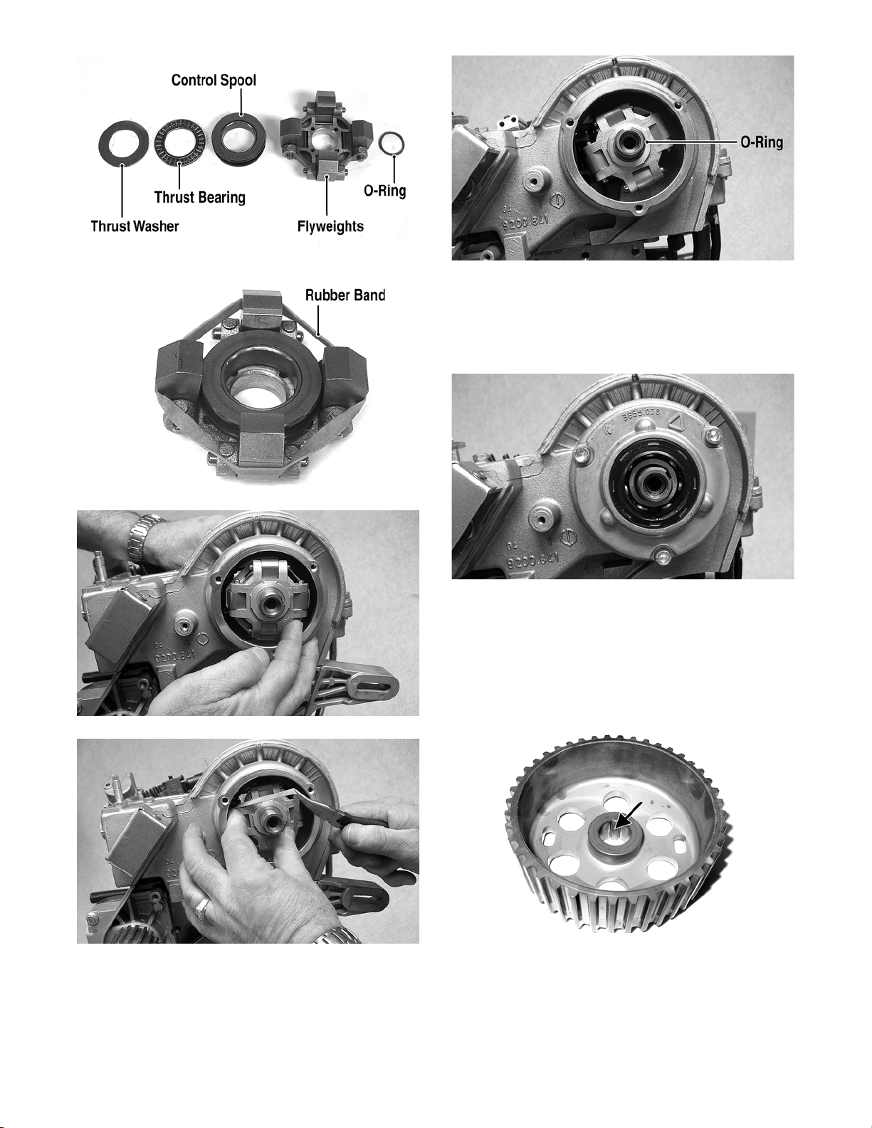
6. Place control spool, thrust bearing, and thrust
washer into the governor flyweight assembly and
secure the flyweights with a rubber band; then
place assembly onto the camshaft with a new Oring. Make sure to remove the rubber band.
28
DE258A
www.mymowerparts.com
For Discount Arctic Cat Parts Call 606-678-9623 or 606-561-4983
DE279A
DE531A
DE246A
7. Using a new O-ring, coat the flange of the camshaft bearing retainer and the camshaft support
housing with clean engine oil and install into the
cylinder head. Secure with the three cap screws
and tighten to 7 ft-lb.
DE296
8. Being careful not to damage the oil seal, lightly
coat the camshaft drive pulley flange with clean
engine oil and install on the camshaft.
NOTE: The camshaft drive pulley has a molded
extrusion in the pulley bore that must engage the
keyway in the camshaft.
DE535
DE536
9. Secure the camshaft drive pulley to the camshaft
with a washer and cap screw; then using an appropriate holding tool, tighten the cap screw to 59 ftlb.
www.mymowerparts.com
DE574A
29
 Loading...