

Page 1
INSTRUCTIONS FOR INSTALLATION AND USE
MONTAGE- UND GEBRAUCHSANWEISUNG
INSTRUCTIONS POUR L'INSTALLATION ET L’UTILISATION
ISTRUZIONI PER L'INSTALLAZIONE E L’USO
INSTRUCCIONES PARA INSTALACIÓN Y USO
INSTRUÇÕES DE INSTALAÇÃO Y UTILIZAÇÃO
AANWIJZING VOOR GEBRUIK EN INSTALLATIE
Page 2
ENGLISH
DESCRIPTION
The hood may be installed in the filtering or the ducting version.
Filtering version (Fig. 1): The hood aspirates the kitchen air saturated with fumes and odours, purifies it
through the grease filters and charcoal filters and returns clean air into the room. For constant efficiency, the
charcoal filters must be replaced periodically.
Ducting version (Fig. 2): The hood aspirates the kitchen air saturated with fumes and odours, passes it through
the grease filters and expels it to the outside through an outlet pipe. With this version the charcoal filters are
not required.
Decide from the outset on the type of installation (filtering or ducting). For greater efficiency, we recommend
you install the hood in the ducting version (if possible).
INSTALLATION
Before beginning installation, to better handle the hood, we advise removing the metal grid or the metal filter/s
(depending on the model purchased by you).
To remove the metal grid (Fig. 3), push the two stops towards the inside of the hood and turn the grid until this
can be removed.
To remove the metal filter/s (Fig. 4A or 4B), in line with the handle, push the stop inwards and pull the filter down.
INSTALLATION IN DUCTING VERSION:
Before fixing, the outlet pipe for air evacuation to the outside must be installed. Use an outlet pipe with:
- minimum indispensable length; - Minimum possible bends (maximum angle of bend:90°); - certified material
(according to the State); - an as smooth as possible inside. It is also advisable to avoid any drastic changes
in pipe cross-section (recommended diameter: 125 mm). For air evacuation to the outside, follow all the instructions
given on the “Warnings” sheet.
Decide on the position of the hole for the air outlet: The hole may be in the wall or the ceiling, according
to your requirements, but must be in vertical line with your hob. Bear in mind that the hood can expel air through
the rear opening A (Fig. 5) or through the top opening B.
Select the type of configuration most suited to your needs and proceed by mounting the flange C (Fig. 6)
on the opening selected for air evacuation (A or B): make the 3 flange clips and the catch D coincide with the
slots on the hood; slightly turn the flange clockwise until it locks. Close the other opening by mounting the “cap”
(E) in the same way: Make the 3 cap clips and the catch F coincide with the slots on the hood; slightly turn
the cap clockwise until it locks.
Drill the hole in the wall for the air outlet (133 mm diameter) referring to Fig. 7 where the measurements for
the various possibilities are indicated.
Prepare a suitable power supply. For the electrical connection, follow all the other instructions on the “Warnings”
sheet.
Proceed with fixing the hood: Based on your requirements, you can fit the hood on the wall or on a wall
unit of your kitchen. IMPORTANT: Respect the distance between the hob and lower part of the hood which must
be at least 650 cm.
Fixing to the wall: If you use the top opening B for the air outlet through the wall unit, before fixing the
hood to the wall, drill a hole of 133 mm diameter in the wall unit (Fig. 8). In any case, check the position of
the power outlet and consider where the power cable will run, since a hole might have to be made in the wall
unit to accommodate it. Draw a line on the wall in vertical line with your hob. Mark the 4 holes to be drilled
in the wall, respecting the distances indicated in Fig. 9; Make the 4 holes and fit the 4 screw anchors provided.
Take 2 of the screws provided (Fig. 10G) and insert them in the topmost screw anchors without however screwing
them down completely. Hang the hood on the 2 screws; Working from inside the hood, tighten the 2 screws
completely. Now proceed with final fixing by fitting the other 2 screws H (Fig. 11). Connect a flexible tube to the
hood flange, using a metal hose clamp. Tube and hose clamps are not provided. Make the electrical connection.
Fitting under wall unit: If you use the top opening B for the air outlet through the wall unit, before fixing
the hood to the unit, drill a hole of 133 mm diameter in the wall unit (Fig. 8). In any case, check the position
of the power outlet and consider where the power cable will run, since a hole might have to be made in the wall
unit to accommodate it. Drill 4 holes in the wall unit, respecting the distances indicated in Fig. 12. Push the hood
up against the wall unit and insert the 4 screws operating from inside the wall unit (the 4 screws are not provided).
Connect a flexible tube to the hood flange, using a metal hose clamp. Tube and hose clamps are not provided.
Make the electrical connection.
Installation is now complete. We recommend you:
• CHECK THAT THE DUCTING-FILTERING LEVER IS IN THE RIGHT POSITION: The lever is found on the motor
unit and must be positioned on the symbol (P) in the case of installation in ducting version (Fig. 13).
• also remember that the use of charcoal filter/s is not necessary with the ducting version; if these are fitted,
remove them and proceed as following according to the model type purchased:
Page 3
- if the hood features round charcoal filters (Fig. 14R), remove the charcoal filter by turning it clockwise.
- if the hood features a panel type charcoal filter (Fig. 15A or 16A or 17A), remove the charcoal filter by first
of all removing the two filter retainers M.
INSTALLATION IN FILTERING VERSION:
Prepare a suitable power supply. For the electrical connection, follow all the other instructions on the “Warnings”
sheet.
The 2 openings (A and B) on the hood (Fig. 5) must not be closed, since the air is recirculated into the
room through the front vents.
Proceed with fixing the hood: Based on your requirements, you can fit the hood on the wall or on a wall
unit of your kitchen. IMPORTANT: Respect the distance between the hob and lower part of the hood which must
be at least 650 cm.
Fixing to the wall: Before fixing the hood to the wall, check the position of the power outlet and consider
where the power cable will run, since a hole might have to be made in the wall unit to accommodate it. Draw
a line on the wall in vertical line with your hob. Mark the 4 holes to be drilled in the wall, respecting the distances
indicated in Fig.9; Make the 4 holes and fit the 4 screw anchors provided. Take 2 of the screws provided (Fig.
10G) and insert them in the topmost screw anchors without however screwing them down completely. Hang the
hood on the 2 screws; Working from inside the hood, tighten the 2 screws completely. Now proceed with final
fixing by fitting the other 2 screws H (Fig. 11). Make the electrical connection.
Fitting under wall unit: Before fixing the hood to the wall unit, check the position of the power outlet and
consider where the power cable will run, since a hole might have to be made in the wall unit to accommodate
it. Drill 4 holes in the wall unit, respecting the distances indicated in Fig. 12. Push the hood up against the wall
unit and insert the 4 screws operating from inside the wall unit (the 4 screws are not provided). Make the electrical
connection.
Installation is now complete. We recommend you:
• CHECK THAT THE DUCTING-FILTERING LEVER IS IN THE RIGHT POSITION: The lever is found on the motor
unit and must be positioned on the symbol (Q) in the case of installation in filtering version (Fig. 13).
• also remember that charcoal filter/s must be used in the case of the filtering version; check to see whether
such filters are already fitted; if necessary, proceed to fit as follows, depending on the model type purchased:
- if the hood features round charcoal filters (Fig. 18R), fit the charcoal filter by turning anti-clockwise.
- if the hood features a panel type charcoal filter/s (Fig. 15A or 17A), position the charcoal filter inside and fit
the two filter retainers to secure the charcoal filter.
OPERATION
Depending on the model, the unit is equipped with the following controls:
Controls as in Fig. 19: A = Light switch. B = Motor ON/OFF switch - speed I C = switch - speed II D
= switch - speed III E = Motor on light.
Controls as in Fig. 20: A = Light switch; position 0: light off; position 1: light on. B = Motor switch; position
0: motor off; position 1-2-3: Motor on at speed I, II and II. C = Motor on light.
Grease filter/s: Depending on the version, the hood features different types of grease filters:
Modular metal filter/s (of the type shown in Fig. 21 or 22): these are metal filters and must be periodically cleaned,
depending on extent of operation (at least every two months). Wash the filters with neutral detergent. To remove
the filters, in line with the handle, push the stop inwards and pull the filter down (Fig. 4A or 4B).
Panel type metal filter (as shown in Fig. 23N): this is a metal filter and is positioned inside the metal grid; the
filter must be periodically cleaned, depending on extent of operation (at least every two months). Wash the filter
with neutral detergent. To remove the filter, first of all remove the metal grid by pushing the two stops towards
the inside of the hood (Fig. 3); subsequently remove the two filter retainers inside the metal grid and remove the
panel type metal filter.
Panel type synthetic filter (as shown in Fig. 24P): this filter is made of white synthetic fibres and is located
inside the metal grid; it cannot be cleaned, but must be replaced from time to time according to use (at least
every two months). To remove the filter, first of all remove the metal grid, push the two stops towards the inside
of the hood (Fig. 3); next, remove the two filter retainers inside the metal grid and remove the panel type synthetic
filter.
Charcoal filter/s: the charcoal filters must be periodically replaced depending on extent of operation - on
average every 6 months. To remove the charcoal filters, proceed as follows, depending on the model purchased:
- if the hood features round charcoal filters (Fig. 14R), remove the charcoal filter by turning clockwise.
- if the hood features a panel type charcoal filter (Fig. 16A or 17A), remove the charcoal filter by first of all removing
the two filter retainers M.
Lighting:
To access the incandescent lamps, remove the metal grid or metal filter/s (depending on the model you have
purchased): to remove the metal grid (Fig. 3), push the two stops towards the inside of the hood and turn the
grid until this can be removed. To remove the metal filter/s (Fig. 4A or 4B), in line with the handle, push the stop
inwards and pull the filter down. Replace with lamps of the same kind (Fig. 25).
Warning: If you have a hood in the version with 2 motors, to take out the bulbs remove the glass light fitting
Page 4
proceeding as follows: prise the catches of the light fitting at point A and simultaneously move the glass of the
light fitting upwards (Fig. 26). If the round charcoal filters are mounted on your appliance, remove them first.
DEUTSCH
BESCHREIBUNG
Die Haube kann als Umluftversion oder als Abluftversion installiert werden.
Umluftversion (Abb. 1): die Haube saugt die mit Rauch und Gerüchen gesättigte Luft an und reinigt sie durch
die Fett- und die Kohlefilter. Danach wird die saubere Luft wieder in den Raum geleitet. Um die gleichmäßige
Wirksamkeit der Kohlefilter zu erhalten, müssen sie regelmäßig ausgetauscht werden.
Abluftversion (Abb. 2): die Haube saugt die mit Rauch und Gerüchen gesättigte Luft an, leitet sie durch
die Fettfilter und gibt sie über ein Abführungsrohr nach außen ab. Diese Version benötigt keine Kohlefilter.
Entscheiden Sie sich von Anfang an für einen Installationstyp (Umluft oder Abluft). Um eine größere Wirkung
zu erzielen, empfehlen wir die Installation einer Haube in Abluftversion (falls möglich).
INSTALLATION
Vor Beginn des Einbaus sollten zur leichteren Handhabung der Haube das Metallgitter oder die/der Metallfilter (je
nach dem von Ihnen erworbenen Modell) entfernt werden.
Zum Entfernen des Metallgitters (Abb. 3), die 2 Festhalter ins Innere der Haube drücken und das Gitter drehen,
bis es sich abnehmen läßt.
Zum Entfernen die/der Metallfilter (Abb. 4A oder 4B), den Festhalter in der Nähe des Griffs nach innen drücken
und den Filter nach unten ziehen.
INSTALLATION DER ABLUFTVERSION:
Vor der Befestigung muss das Rohr zur Abführung der Luft nach außen angebracht werden. Ein Abführungsrohr
verwenden, das folgende Eigenschaften besitzt: - erforderliche Mindestlänge; - so wenig Kurven wie möglich
(maximale Kurvenkrümmung:90°); - zulässiges Material (Landesnormen); - Innenseite so glatt wie möglich. Es wird
außerdem empfohlen, starke Wechsel des Rohrdurchmessers zu vermeiden (empfohlener Durchmesser: 125 mm).
Für die Luftabführung nach außen alle weiteren Angaben im Blatt “Hinweis” befolgen.
Wählen Sie die Position der Öffnung für die Luftabführung: Die Öffnung kann sich je nach Ihren Bedürfnissen
an der Wand oder der Decke befinden, und muss sich in jedem Fall in senkrechter Linie zu Ihrem Kochfeld befinden.
Beachten Sie, dass die Haube die Luft über die hintere Öffnung A (Abb. 5) ableiten kann oder über die obere
Öffnung B.
Wählen Sie die für Sie am besten geeignete Lösung und fahren Sie mit der Montage des Flansches C (Abb.
6) auf der zur Luftableitung gewählten Öffnung fort (A oder B)die 3 Laschen des Deckels und den Feststeller D
auf die Schlitze auf der Haube ausrichten; den Flansch leicht im Uhrzeigersinn drehen, bis er sperrt. Die andere
Öffnung schließen, dazu den “Deckel” (E) in der gleichen Weise darauf montieren: die 3 Laschen des Deckels
und den Feststeller F auf die Schlitze auf der Haube ausrichten; den Deckel leicht im Uhrzeigersinn drehen, bis
er sperrt.
Das Bohrloch in der Wand zur Ableitung der Luft ausführen (Durchmesser 133 mm), hierbei die Abb. 7 beachten,
in der die Maße für die verschiedenen Möglichkeiten angegeben sind.
Für eine angemessene Stromversorgung sorgen. Für den Elektroanschluss beachten Sie alle Angaben im Blatt
“Hinweis”.
Fahren Sie mit der Befestigung des Gerätes fort: je nach Ihren Bedürfnissen können Sie die Haube an der
Wand oder am Oberschrank Ihrer Küche befestigen. WICHTIG: der Abstand zwischen der Haube und dem Kochfeld
muss mindestens 650 cm betragen.
Wandmontage: Wenn Sie die obere Öffnung B für die Luftableitung durch den Oberschrank benutzen, muss
vor Befestigung der Haube an der Wand im Oberschrank ein Loch mit einem Durchmesser von 133 mm angebracht
werden (Abb. 8). In jedem Fall muss die Position der Steckdose festgestellt und der eventuelle Verlauf des
Speisekabels berücksichtigt werden (für das Speisekabel könnte eine spezielle Öffnung im Oberschrank erforderlich
werden). Zeichnen Sie eine Linie auf die Wand, vertikal zu Ihrem Kochfeld. Markieren Sie die 4 anzubringenden
Löcher auf der Wand, dabei sind die in Abb. 9 angegebenen Maße zu beachten; die 4 Bohrungen ausführen und
die 4 (mitgelieferten) Dübel einstecken.Nehmen Sie 2 der mitgelieferten Schrauben (Abb. 10G) und fügen Sie sie
in die weiter oben befindlichen Dübel, ohne sie jedoch vollständig anzuschrauben. Bringen Sie die Haube zur Wand
und hängen Sie sie an den 2 Schrauben auf; Von der Innenseite der Haube aus müssen die beiden Schrauben
gut angezogen werden. Nehmen Sie die endgültige Befestigung vor, dazu die beiden Schrauben H einfügen (Abb.
11). Schließen Sie einen Schlauch an den Flansch des Gerätes an, dazu eine Metallschelle verwenden. Schlauch
und Schellen werden nicht mitgeliefert. Den elektrischen Anschluss herstellen.
Befestigung an der Unterseite des Hängeschranks: Wenn Sie die obere Öffnung B für den Luftaustritt durch
den Oberschrank benutzen, ist der Oberschrank vor Befestigung der Haube am Schrank mit einem Loch mit dem
Durchmesser 133 mm zu versehen (Abb. 8). In jedem Fall muss die Position der Steckdose festgestellt und der
Page 5
eventuelle Verlauf des Speisekabels berücksichtigt werden (für das Speisekabel könnte eine spezielle Öffnung im
Oberschrank erforderlich werden). 4 Löcher in den Oberschrank bohren, dabei die in Abb. 12 angegebenen Maße
einhalten. Die Haube neben den Oberschrank bringen und 4 Schrauben einfügen, dabei vom Innern des Oberschranks
aus vorgehen (die 4 Schrauben werden nicht mitgeliefert). Schließen Sie einen Schlauch an den Flansch des Gerätes
an, dazu eine Metallschelle verwenden. Schlauch und Schellen werden nicht mitgeliefert. Den elektrischen Anschluss
herstellen.
Nun ist der Einbau beendet ; wir empfehlen folgendes:
• ÜBERPRÜFEN, DASS SICH DER HEBEL ANSAUGEN-FILTERN IN DER KORREKTEN POSITION BEFINDET : der
Hebel befindet sich auf dem Motoraggregat und muss auf dem Symbol positioniert sein (P) wenn die Abluftversion
installiert ist (Abb. 13).
• Beachten Sie, dass für die Abluftversion keine Kohlefilter benötigt werden; sollten diese bereits montiert sein,
entfernen Sie sie unter Befolgung der nachstehenden Anweisungen entsprechend dem von Ihnen erworbenen Modell:
- wenn die Haube mit runden Kohlefiltern ausgestattet ist (Abb. 14R), entfernen Sie die Kohlefilter durch Drehen
derselben im Uhrzeigersinn.
- wenn die Haube mit einem Kohlefilterpaneel ausgestattet ist (Fig. 15A oder 16A oder 17A), entfernen Sie den
Kohlefilter durch vorheriges Abnehmen der beiden Filterhalter M.
INSTALLATION UMLUFTVERSION:
Für eine angemessene Stromversorgung sorgen. Für den Elektroanschluss beachten Sie alle Angaben im Blatt
“Hinweis”.
Die beiden Öffnungen (A und B) auf dem Gerät (Abb. 5) dürfen nicht geschlossen sein, da die Luft durch
die vorderen Schlitze wieder in den Raum geleitet wird.
Fahren Sie mit der Befestigung des Gerätes fort: je nach Ihren Bedürfnissen können Sie die Haube an der
Wand oder am Oberschrank Ihrer Küche befestigen. WICHTIG: der Abstand zwischen der Haube und dem Kochfeld
muss mindestens 650 cm betragen.
Wandmontage: Vor Befestigung des Gerätes an der Wand die Position der Steckdose überprüfen und den
eventuellen Verlauf des Speisekabels berücksichtigen (für das Speisekabel könnte eine spezielle Öffnung am
Oberschrank erforderlich werden). Zeichnen Sie eine Linie auf die Wand, vertikal zu Ihrem Kochfeld. Markieren Sie
die 4 anzubringenden Löcher auf der Wand, dabei sind die in Abb. 9 angegebenen Maße zu beachten; die 4
Bohrungen ausführen und die 4 (mitgelieferten) Dübel einstecken. Nehmen Sie 2 der mitgelieferten Schrauben
(Abb.10G) und fügen Sie sie in die weiter oben befindlichen Dübel, ohne sie jedoch vollständig anzuschrauben.
Bringen Sie die Haube zur Wand und hängen Sie sie an den 2 Schrauben auf; von der Innenseite der Haube aus
müssen die beiden Schrauben gut angezogen werden. Nehmen Sie die endgültige Befestigung vor, dazu die beiden
Schrauben H einfügen (Abb. 11). Den elektrischen Anschluss herstellen.
Befestigung an der Unterseite des Hängeschranks: Vor Befestigung des Gerätes am Oberschrank die Position
der Steckdose überprüfen und den eventuellen Verlauf des Speisekabels berücksichtigen (für das Speisekabel
könnte eine spezielle Öffnung am Oberschrank erforderlich werden). 4 Löcher in den Oberschrank bohren, dabei
die in Abb.12 angegebenen Maße einhalten. Die Haube neben den Oberschrank bringen und 4 Schrauben einfügen,
dabei vom Innern des Oberschranks aus vorgehen (die 4 Schrauben werden nicht mitgeliefert). Den elektrischen
Anschluss herstellen.
Nun ist der Einbau beendet ; wir empfehlen folgendes:
• ÜBERPRÜFEN, DASS SICH DER HEBEL ANSAUGEN-FILTERN IN DER KORREKTEN POSITION BEFINDET: der
Hebel befindet sich auf dem Motoraggregat und muss auf dem Symbol (Q) positioniert sein, wenn die Umluftversion
installiert ist (Abb. 13).
• Beachten Sie, dass bei der Umluftversion der Gebrauch von Kohlefilter (n) erforderlich ist; uberprüfen Sie, ob
die Filter bereits installiert sind; falls erforderlich, montieren Sie diese wie nachstehend beschrieben ist, entsprechend
dem von Ihnen erworbenen Modell:
- wenn die Haube mit runden Kohlefiltern ausgestattet ist (Abb. 18R), hängen Sie den Kohlefilter durch Drehen
desselben im Gegenuhrzeigersinn ein.
- wenn die Haube mit einem Kohlefilterpaneel ausgestattet ist (Abb. 15A oder 16A oder 17A), legen Sie das(die)
Kohlefilterpaneel(e) auf die innere Seite der Fettfilterkassette und setzen Sie die zwei Halter wieder ein, um das
Kohlefilterpaneel zu befestigen.
FUNKTIONSWEISE
Je nach Version ist das Gerät mit folgenden Bedienungsarten ausgestattet:
Bedienung in Abb. 19:
A = Lichtschalter. B = Motorschalter ON/OFF bei der I. Geschwindigkeit. C = Schalter II. Geschwindigkeit.
D = Schalter III. Geschwindigkeit. E = Motorfunktionsanzeige.
Bedienung in Abb. 20:
A = Lichtschalter; Position 0: Licht aus; Position 1: Licht an. B = Motorschalter;Position 0: Motor ausgeschaltet;
Position 1-2-3: Motor eingeschaltet mit erster, zweiter und dritter Geschwindigkeit. C: Motorfunktionsanzeige.
Fettfilter:
Je nach Version wird die Haube mit verschiedenen Fettfiltern geliefert:
Metallfilterkassette (wie in Abb. 21 oder 22 gezeigt): diese Filter bestehen aus Metall und sind je nach Benutzung
Page 6

periodisch zu reinigen (wenigstens alle zwei Monate). Den Filter mit neutralem Reinigungsmittel abwaschen. Zum
Entfernen der Filter (Abb. 3), den Festhalter in der Nähe des Griffs nach innen drücken und den Filter nach unten
ziehen (Abb. 4A oder 4B).
Metallfilterpaneele (wie in Abb. 23N gezeigt): dieser aus Metall bestehende Filter befindet sich im Innern des
Metallgitters und ist je nach Benutzung periodisch (wenigstens alle zwei Monate) zu reinigen. Den Filter mit neutralem
Reinigungsmittel abwaschen. Zum Entfernen der Metallfilter, das Metallgitter abnehmen, dazu die beiden Feststeller
nach dem Haubeninnern schieben (Abb. 3); anschließend die 2 im Innern des Metallgitters befindlichen Filterhalter
entfernen und Metallfilterpaneel abnehmen.
Synthetikfilterpaneel (wie in Abb. 24P gezeigt): dieser aus weißer Synthetikfaser bestehende Filter befindet sich
im Innern des Metallgitters und ist je nach Benutzung periodisch (wenigstens alle zwei Monate) zu ersetzen. Zum
Entfernen der Kohlefilter, das Metallgitter abnehmen, dazu die beiden Feststeller nach dem Haubeninnern schieben
(Abb. 3); anschließend die 2 im Innern des Metallgitters befindlichen Filterhalter entfernen und Synthetikfilterpaneel
herausnehmen.
Kohlefilter: Der(die) Kohlefilter je nach Benutzung ersetzen; in der Regel alle 6 Monate. Zum Entfernen der
Kohlefilter, wie folgt vorgehen, je nach dem von Ihnen erworbenen Modell:
- wenn die Haube mit runden Kohlefiltern ausgestattet ist (Abb. 14R), entfernen Sie den Kohlefilter durch Drehen
derselben im Uhrzeigersinn.
- wenn die Haube mit einem Kohlefilterpaneel (Abb. 15A oder 16A oder 17A) ausgestattet ist, ist der Kohlefilter
durch vorheriges Entfernen der 2 Filterhalter M herauszunehmen.
Beleuchtung:
Um an die Glühlampen zu gelangen, muß je nach dem von Ihnen erworbenen Modell das Metallgitter oder die
Metallfilterkassette(n) abgenommen werden: Zum Entfernen des Metallgitters (Abb. 3), die 2 Festhalter ins Innere
der Haube drücken und das Gitter drehen, bis es sich abnehmen läßt. Zum Entfernen des(der) Metallfilter (Abb.
4A oder 4B), den Festhalter in der Nähe des Griffs nach innen drücken und den Filter nach unten ziehen. Die
Lampen durch neue des gleichen Typs ersetzen (Abb. 25).
Achtung: Wenn Sie die Dunstabzugshaube in der 2-Motoren-Version besitzen, muss zum Wechsel der Lampen die
Glasblende wie folgt entfernt werden: in Punkt A auf die Halterungen der Blende drücken und gleichzeitig das Glas
der Blende nach oben schieben (Abb. 26); sind an Ihrem Gerät die runden Kohlefilter montiert, so müssen diese
zuvor entfernt werden.
FRANCAIS
DESCRIPTION
Cette hotte peut être installée en version recyclage ou en version aspirante.
Version Recyclage (Fig. 1) : votre hotte aspire l’air de la cuisine imprégné de fumée et d’odeurs, en l’épurant
à travers les filtres à graisse ainsi qu’à travers les filtres à charbon pour le renvoyer dans la pièce, propre. Afin
que votre hotte soit efficace d’une façon constante, il est nécessaire de remplacer les filtres à charbon
périodiquement.
Version aspirante (Fig. 2) : votre hotte aspire l’air de la cuisine imprégnée de fumée et d’odeurs, en le faisant
passer à travers les filtres à graisse, puis en expulsant à l’extérieur à travers un tuyau d’évacuation. Dans cette
version l’emploi de filtres à charbon n’est pas nécessaire.
Vous devez décider dès le début quel type d’installation vous souhaitez (recyclage ou aspirante). Afin d’avoir
une hotte au rendement optimal, nous vous conseillsons d’installer une hotte version aspirante (si cela est possible).
INSTALLATION
Avant de commencer l’installation, pour mieux manipuler la hotte, il est conseillé d’enlever la grille métallique ou
le/les filtre/s métalliques (en fonction du modèle en votre possession).
Pour enlever la grille métallique (Fig. 3), poussez les deux fixations vers l’intérieur de la hotte et tournez la grille
jusqu’à son extraction.
Pour enlever le/les filtre/s métalliques (Fig. 4A ou 4B), en face de la poignée, poussez la fixation vers l’intérieur
puis tirez le filtre vers le bas.
INSTALLATION VERSION ASPIRANTE :
Avant de l’assembler, il est nécessaire de prévoir le tuyau pour l’évacuation de l’air à l’extérieur. Employez
un tuyau d’évacuation qui a : - la longueur minimum indispensable ; - le moins de courbes possible (angle maximum
des courbes : 90°) ; - qui soit fait d’une matière autorisée par les normes en vigueur; - la surface intérieure la
plus lisse possible. Nous vous conseillons aussi d’éviter les changements brusques de section du tuyau (diamètre
conseillé : 125 mm). Pour l’évacuation de l’air à l’extérieur, suivez toutes les autres indications données par le
feuille “Attention”.
Etudiez la position du trou pour l’évacuation de l’air : ce trou peut être fait dans le mur ou dans le plafond,
suivant vos exigences, il doit en tout cas être fait verticalement par rapport à votre plan de cuisson. Tenez compte
Page 7

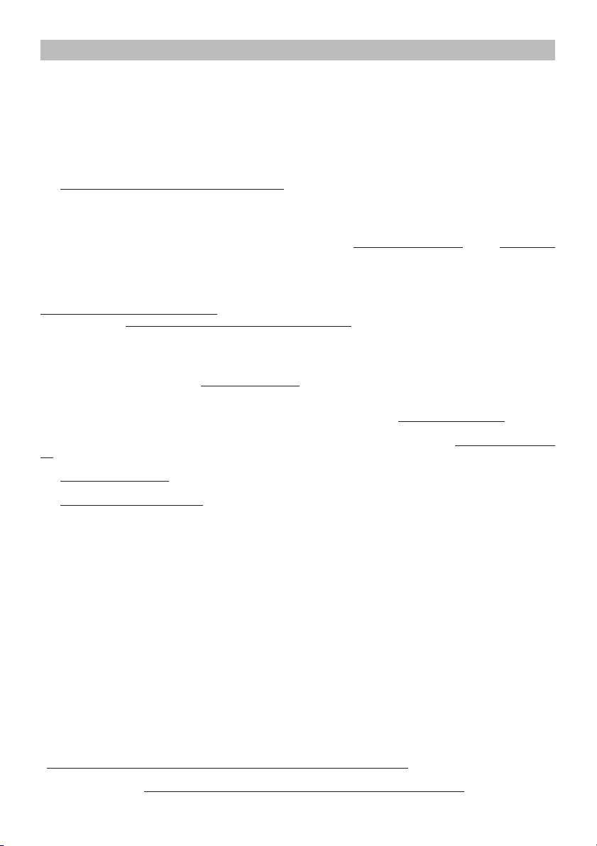
Wiring Diagram (1 MOTOR) - Elektrischer Schaltplan (1 MOTOR) Schéma Électrique (1 MOTEUR) - Schema Elettrico (1 MOTORE) -
Esquema Eléctrico (1 MOTOR) - Esquema Eléctrico (1 MOTOR) -
Elektrisch Schema (1 MOTOR)
HOOD WITH SLIDE CONTROLS - GERÄT MIT SCHIEBEKNOPF-BEDIENUNG HOTTE AVEC COMMANDES A CHARIOT - CAPPA CON COMANDI A SLITTA CAMPANA CON MANDOS DESLIZANTES - EXAUSTOR COM COMANDOS DESLIZANTES AFZUIGKAP MET SCHUIFKNOPBEDIENING
HOOD WITH BUTTON CONTROLS - GERÄT MIT TASTENBEDIENUNG
HOTTE AVEC COMMANDES A BOUTONS - CAPPA CON COMANDI A PULSANTI
CAMPANA CON PULSANTES - EXAUSTOR COM COMANDOS DE BOTÕES
AFZUIGKAP MET DRUKKNOPBEDIENING
Page 8

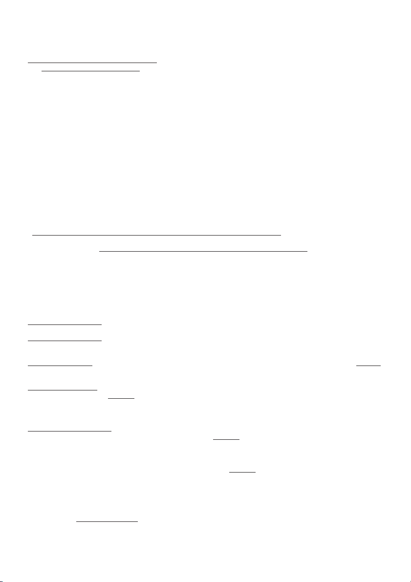
Wiring Diagram (2 MOTORS) - Elektrischer Schaltplan (2 MOTOREN) -
Schéma Électrique (2 MOTEURS) - Schema Elettrico (2 MOTORI) -
Esquema Eléctrico (2 MOTORES) - Esquema Eléctrico (2 MOTORES) -
Elektrisch Schema (2 MOTOREN)
HOOD WITH SLIDE CONTROLS - GERÄT MIT SCHIEBEKNOPF-BEDIENUNG HOTTE AVEC COMMANDES A CHARIOT - CAPPA CON COMANDI A SLITTA CAMPANA CON MANDOS DESLIZANTES - EXAUSTOR COM COMANDOS DESLIZANTES AFZUIGKAP MET SCHUIFKNOPBEDIENING
HOOD WITH BUTTON CONTROLS - GERÄT MIT TASTENBEDIENUNG
HOTTE AVEC COMMANDES A BOUTONS - CAPPA CON COMANDI A PULSANTI
CAMPANA CON PULSANTES - EXAUSTOR COM COMANDOS DE BOTÕES
AFZUIGKAP MET DRUKKNOPBEDIENING
Page 9

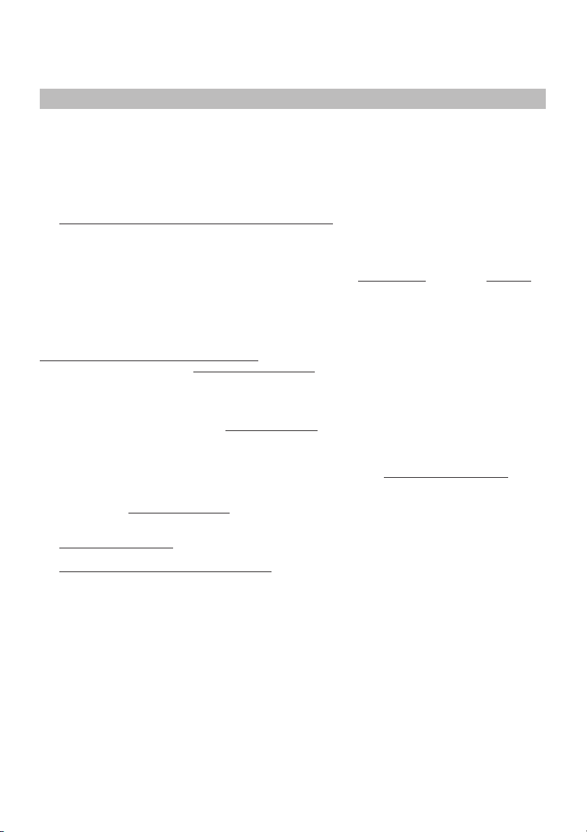
1
2
3
5
B
A
C
4A
4B
D
F
6
E
Page 10

7
Ø133
8
85
9
Ø 8mm
min650
min650
min
940
Ø 133
85
720
10
G
G
A
=
=
44
732
MODELS A
50cm 44cm
55cm 49cm
60cm 54cm
70cm 64cm
80cm 74cm
90cm 84cm
11
H
Page 11

12
Ø 6mm
MODELS X
50cm 41cm
55cm 46cm
60cm 51cm
70cm 61cm
80cm 71cm
90cm 81cm
256
34
X
=
=
13
15
17
P
M
M
R
14
Q
M
A
16
18
A
A
R
Page 12

19
A
B
C
D
E
C
A
B
20
21
23
24
22
N
P
26
25
04306555/3 - SP2000 sen.nor.
Page 13

ENGLISH
If the light bulbs need changing, slacken the light cover by disconnecting the screw
“A” and remove the bulb itself.
DEUTSCH
Um die Lampe austauschen zu können, muß zunächst die Lichtabdeckung durch die
Umdrehung der Schraube “A”, entfernt werden.
FRANCAIS
Pour acceder à l’ampoule d’éclairage, retirer le cache-lumière en dévissant la vis
“A”.
ITALIANO
Per sostituire le lampade di illuminazione rimuovere la plafoniera dopo aver disinserito
la vite di fermo “A”
ESPAÑOL
Para sustituir las bombillas de iluminación quitar el plafón después de haber
destornillado el tornillo “A” que lo fija.
PORTUGUÊS
Para substituir as lâmpadas de iluminação remover a cobertura das lâmpadas depois
de ter tirado o parafuso “A” de fixação.
NEDERLANDS
Voor vervanging van de lamp van de verlichting, verwijder het doorzichtige plaatje nadat
de sluitschroef “A” is losgedraait.
SUOMI
Lampun vaihto. Poista lampun suojus kiertämällä auki ruuvi “A”
Page 14

NORSK
For å bytte ut lyspærene, løsne festeskruen A og ta av lampens deksel
POLSKI
Aby wymieniÊ lampÍ oúwietlenia zdjπÊ plafonierÍ po uprzednim wyjÍciu wkrÍtu
ustalajπcego ÑAî
SVENSKA
För att byta ut lamporna, lossa låsskruven A och ta bort lampkåpan
ΕΛΛΗΝΙΚΑ
Για την αντικατάσταση των λυχνιών φωτισµού αφαιρέστε την πλαφονιέρα αφού
προηγουµένως βγάλετε τη βίδα στερέωσης “Α”
ОПИСАНИЕ
Для замены осветительных ëàìï снимите плафон, предварительно отвинтив
стопорный винт “А”.
tyrbu
rjAl hrqth trwnm tA ryshl ?y hrwAth twrwnm tA [yljhl ydk
.”A” qwzyjh grwb tA <yrrj?m?
DANSK
For at skifte pærerne ud, sørg for at løsne låseskruen A og tag lampens dæksel af
»ESKY
Chcete-li vymÏnit û·rovku osvÏtlenÌ, odmontujte kryt tak, ûe nejprve odöroubujete
upevÚovacÌ öroub ìAî
F. Err. Corr. Smontaggio Plafoniera 04307136
 Loading...