

Page 1

i
ArthroCare®Atlas™ System
User’s Manual
Table of Contents by Language
ArthroCare Atlas System User’s Manual – English . . . . . . . . . . . . . . . . . . . . . . . . . . . . . . . . . . . . . . . . . 1
Manuel de l’opérateur du système Atlas ArthroCare – Français . . . . . . . . . . . . . . . . . . . . . . . . . . . . . . . 31
Gebrauchsanweisung für ArthroCare System Atlas – Deutsch . . . . . . . . . . . . . . . . . . . . . . . . . . . . . . . . 61
Page 2

ii
ArthroCare®Atlas™ System
User’s Manual
Page 3
1
ArthroCare®Atlas™ System
User’s Manual
ENGLISH
ArthroCare®Atlas™ System
User’s Manual
Page 4

2
ArthroCare®Atlas™ System
User’s Manual
Page 5

3
ArthroCare®Atlas™ System
User’s Manual
ENGLISH
This equipment has been tested and found to comply with the limits for medical devices to IEC 60601-1-2:1994.
These limits are designed to provide reasonable protection against harmful interference in a typical medical installation. This equipment generates, uses, and can radiate radiofrequency energy and, if not installed and used in accordance with the instructions, may cause harmful interference to other devices in the vicinity. If this equipment does
cause harmful interference to other devices, which can be verified by turning the equipment off and on, the user is
encouraged to try to correct the interference by one or more of the following measures:
• Reorient or relocate the receiving device,
• Increase the separation between the affected equipment and the Controller,
• Connect the affected equipment to an outlet or circuit different from that to which the Controller is connected, or
• Consult the manufacturer or field service technician for help.
Page 6

4
ArthroCare®Atlas™ System
User’s Manual
Page 7

ArthroCare®Atlas™ System
User’s Manual
ENGLISH
5
Table of Contents
Description, Indications for Use, and Contraindications . . . . . . . . . . . . . . . . . . . . . . . . . . . . . . . . . . . . . . . . . . . .7
Description . . . . . . . . . . . . . . . . . . . . . . . . . . . . . . . . . . . . . . . . . . . . . . . . . . . . . . . . . . . . . . . . . . . . . . . . . . . . . . . . . .7
Indications for Use . . . . . . . . . . . . . . . . . . . . . . . . . . . . . . . . . . . . . . . . . . . . . . . . . . . . . . . . . . . . . . . . . . . . . . . . . . . .7
Contraindications . . . . . . . . . . . . . . . . . . . . . . . . . . . . . . . . . . . . . . . . . . . . . . . . . . . . . . . . . . . . . . . . . . . . . . . . . . . . .7
System Overview . . . . . . . . . . . . . . . . . . . . . . . . . . . . . . . . . . . . . . . . . . . . . . . . . . . . . . . . . . . . . . . . . . . . . . . . . . . .8
Connection Diagram . . . . . . . . . . . . . . . . . . . . . . . . . . . . . . . . . . . . . . . . . . . . . . . . . . . . . . . . . . . . . . . . . . . . . . . . . .8
Principle of Operation . . . . . . . . . . . . . . . . . . . . . . . . . . . . . . . . . . . . . . . . . . . . . . . . . . . . . . . . . . . . . . . . . . . . . . . .9
Warnings, Precautions, and Adverse Events . . . . . . . . . . . . . . . . . . . . . . . . . . . . . . . . . . . . . . . . . . . . . . . . . . . . .10
Warnings . . . . . . . . . . . . . . . . . . . . . . . . . . . . . . . . . . . . . . . . . . . . . . . . . . . . . . . . . . . . . . . . . . . . . . . . . . . . . . . . . .10
Precautions . . . . . . . . . . . . . . . . . . . . . . . . . . . . . . . . . . . . . . . . . . . . . . . . . . . . . . . . . . . . . . . . . . . . . . . . . . . . . . . .10
Adverse events . . . . . . . . . . . . . . . . . . . . . . . . . . . . . . . . . . . . . . . . . . . . . . . . . . . . . . . . . . . . . . . . . . . . . . . . . . . . . .11
Controls, Indicators, and Alarms . . . . . . . . . . . . . . . . . . . . . . . . . . . . . . . . . . . . . . . . . . . . . . . . . . . . . . . . . . . . . .12
Controls & Indicators . . . . . . . . . . . . . . . . . . . . . . . . . . . . . . . . . . . . . . . . . . . . . . . . . . . . . . . . . . . . . . . . . . . . . . . . .12
Alarms . . . . . . . . . . . . . . . . . . . . . . . . . . . . . . . . . . . . . . . . . . . . . . . . . . . . . . . . . . . . . . . . . . . . . . . . . . . . . . . . . . . .13
Diagram of Controls, Indicators, and Alarms . . . . . . . . . . . . . . . . . . . . . . . . . . . . . . . . . . . . . . . . . . . . . . . . . . . . . . .14
Unpacking, Assembly, and System Check . . . . . . . . . . . . . . . . . . . . . . . . . . . . . . . . . . . . . . . . . . . . . . . . . . . . . . .15
Unpacking . . . . . . . . . . . . . . . . . . . . . . . . . . . . . . . . . . . . . . . . . . . . . . . . . . . . . . . . . . . . . . . . . . . . . . . . . . . . . . . . .15
Assembly and System Check . . . . . . . . . . . . . . . . . . . . . . . . . . . . . . . . . . . . . . . . . . . . . . . . . . . . . . . . . . . . . . . . . . .15
Instructions for Use . . . . . . . . . . . . . . . . . . . . . . . . . . . . . . . . . . . . . . . . . . . . . . . . . . . . . . . . . . . . . . . . . . . . . . . . .16
Operator Training Requirements . . . . . . . . . . . . . . . . . . . . . . . . . . . . . . . . . . . . . . . . . . . . . . . . . . . . . . . . . . . . . . . .16
General System Operation . . . . . . . . . . . . . . . . . . . . . . . . . . . . . . . . . . . . . . . . . . . . . . . . . . . . . . . . . . . . . . . . . . . . .16
Voltage Outputs . . . . . . . . . . . . . . . . . . . . . . . . . . . . . . . . . . . . . . . . . . . . . . . . . . . . . . . . . . . . . . . . . . . . . . . . . . . . .17
System Preparation and Care . . . . . . . . . . . . . . . . . . . . . . . . . . . . . . . . . . . . . . . . . . . . . . . . . . . . . . . . . . . . . . . . .18
System Preparation . . . . . . . . . . . . . . . . . . . . . . . . . . . . . . . . . . . . . . . . . . . . . . . . . . . . . . . . . . . . . . . . . . . . . . . . . .18
Wand Selection . . . . . . . . . . . . . . . . . . . . . . . . . . . . . . . . . . . . . . . . . . . . . . . . . . . . . . . . . . . . . . . . . . . . . . . . . . . . .19
System Shut Down . . . . . . . . . . . . . . . . . . . . . . . . . . . . . . . . . . . . . . . . . . . . . . . . . . . . . . . . . . . . . . . . . . . . . . . . . . .19
System Storage and Transport . . . . . . . . . . . . . . . . . . . . . . . . . . . . . . . . . . . . . . . . . . . . . . . . . . . . . . . . . . . . . . . . .19
Equipment Disposal . . . . . . . . . . . . . . . . . . . . . . . . . . . . . . . . . . . . . . . . . . . . . . . . . . . . . . . . . . . . . . . . . . . . . . . . . .19
Page 8

6
ArthroCare®Atlas™ System
User’s Manual
Cleaning and Sterilization . . . . . . . . . . . . . . . . . . . . . . . . . . . . . . . . . . . . . . . . . . . . . . . . . . . . . . . . . . . . . . . . . . . .20
Controller . . . . . . . . . . . . . . . . . . . . . . . . . . . . . . . . . . . . . . . . . . . . . . . . . . . . . . . . . . . . . . . . . . . . . . . . . . . . . . . . . .20
Foot Control . . . . . . . . . . . . . . . . . . . . . . . . . . . . . . . . . . . . . . . . . . . . . . . . . . . . . . . . . . . . . . . . . . . . . . . . . . . . . . . .20
Wand . . . . . . . . . . . . . . . . . . . . . . . . . . . . . . . . . . . . . . . . . . . . . . . . . . . . . . . . . . . . . . . . . . . . . . . . . . . . . . . . . . . . .21
Patient Cable . . . . . . . . . . . . . . . . . . . . . . . . . . . . . . . . . . . . . . . . . . . . . . . . . . . . . . . . . . . . . . . . . . . . . . . . . . . . . . .21
Maintenance and Troubleshooting . . . . . . . . . . . . . . . . . . . . . . . . . . . . . . . . . . . . . . . . . . . . . . . . . . . . . . . . . . . . .22
Maintenance . . . . . . . . . . . . . . . . . . . . . . . . . . . . . . . . . . . . . . . . . . . . . . . . . . . . . . . . . . . . . . . . . . . . . . . . . . . . . . . .22
Fuse Replacement . . . . . . . . . . . . . . . . . . . . . . . . . . . . . . . . . . . . . . . . . . . . . . . . . . . . . . . . . . . . . . . . . . . . . . . . . . .22
Troubleshooting Guide . . . . . . . . . . . . . . . . . . . . . . . . . . . . . . . . . . . . . . . . . . . . . . . . . . . . . . . . . . . . . . . . . . . . . . . .22
Product Specifications . . . . . . . . . . . . . . . . . . . . . . . . . . . . . . . . . . . . . . . . . . . . . . . . . . . . . . . . . . . . . . . . . . . . . .24
Technical Specifications . . . . . . . . . . . . . . . . . . . . . . . . . . . . . . . . . . . . . . . . . . . . . . . . . . . . . . . . . . . . . . . . . . . . . . .24
Controller Output Graphs . . . . . . . . . . . . . . . . . . . . . . . . . . . . . . . . . . . . . . . . . . . . . . . . . . . . . . . . . . . . . . . . . . . . . .25
Controller Classification and Safety Verification . . . . . . . . . . . . . . . . . . . . . . . . . . . . . . . . . . . . . . . . . . . . . . . . .28
Classification . . . . . . . . . . . . . . . . . . . . . . . . . . . . . . . . . . . . . . . . . . . . . . . . . . . . . . . . . . . . . . . . . . . . . . . . . . . . . . .28
Safety Verification . . . . . . . . . . . . . . . . . . . . . . . . . . . . . . . . . . . . . . . . . . . . . . . . . . . . . . . . . . . . . . . . . . . . . . . . . . .28
Customer Service . . . . . . . . . . . . . . . . . . . . . . . . . . . . . . . . . . . . . . . . . . . . . . . . . . . . . . . . . . . . . . . . . . . . . . . . . . .29
Warranty Information . . . . . . . . . . . . . . . . . . . . . . . . . . . . . . . . . . . . . . . . . . . . . . . . . . . . . . . . . . . . . . . . . . . . . . . . .29
Product Complaints . . . . . . . . . . . . . . . . . . . . . . . . . . . . . . . . . . . . . . . . . . . . . . . . . . . . . . . . . . . . . . . . . . . . . . . . . .29
Symbols Key . . . . . . . . . . . . . . . . . . . . . . . . . . . . . . . . . . . . . . . . . . . . . . . . . . . . . . . . . . . . . . . . . . . . . . . . . . . . . . .30
Page 9

ArthroCare®Atlas™ System
User’s Manual
ENGLISH
7
Description, Indications for Use, and
Contraindications
Description
The ArthroCare®Atlas™ System is a bipolar, radiofrequency (RF) electrosurgical system designed for use in arthroscopic and orthopedic procedures. The System consists of the following components:
1) a bipolar radiofrequency controller;
2) a reusable, non-sterile Power Cord;
3) a reusable, non-sterile Foot Control;
4) a reusable, non-sterile Patient Cable; and
5) a disposable, sterile ArthroWand or Microdebrider Wand.
An optional reusable non-sterile Hand Control is also available for use with the System.
The Controller is the voltage source that delivers RF energy to the treatment site via a reusable Patient Cable and
sterile Wand, or an Integrated Cable Wand (ICW), a sterile Wand/Cable combination.
The reusable Patient Cable is supplied non-sterile and is designed for sterilization prior to use.
The sterile disposable Wand is available in various single or multi-electrode configurations and is supplied separately. It may have a Cable component incorporated into its design to replace the Patient Cable,
The Controller is activated by either a reusable Foot Control or an optional reusable Hand Control.
Indications for Use
The ArthroCare Atlas System is indicated for resection, ablation, and coagulation of soft tissue and hemostasis of
blood vessels in arthroscopic and orthopedic procedures.
Contraindications
The ArthroCare Atlas System is contraindicated in any procedures where a conductive solution is not used. The
System is also contraindicated for patients who have cardiac pacemakers or other electronic implants without specific instructions from the manufacturer of the cardiac pacemaker or implant. Please refer to the Wand Instructions for
Use for a more comprehensive list of contraindications regarding specific procedures.
Page 10
8
ArthroCare®Atlas™ System
User’s Manual
6
5
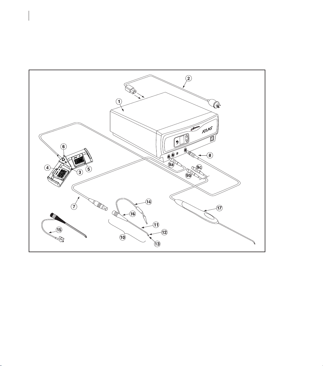
1. Controller 9c. Cable Connector with Black Plug
2. Power Cord 10. Wand
3. Foot Control 11. Shaft
4. Ablation Pedal 12. Return Electrode
5. Coagulation Pedal 13. Active Electrode Tip
6. Set Point Adjustment Button 14. Suction Tube (optional on Wand Style)
7. Patient Cable 15. Irrigant Tube (optional on Wand Style)
8. Controller Connector 16. Handle
9a. Patient Cable Connector 17. Integrated Cable Wand (ICW)
9b. Cable Connector with Gray Plug
System Overview
Connection Diagram
Page 11

ArthroCare®Atlas™ System
User’s Manual
ENGLISH
Principle of Operation
The ArthroCare Atlas Controller is designed to deliver RF energy to the electrode elements located at the distal end
of the sterile single-use Wands. Current flows between the active electrodes elements and the return electrode element, both elements or poles located on the Wand itself in a bipolar configuration, providing a localized energy field.
The result of this arrangement is controlled energy delivery with minimal collateral tissue damage.
The ArthroCare Atlas System works by passing RF energy through a conductive solution (such as normal saline or
Ringer’s lactate) in close proximity to or in contact with the tissue to be treated. The conductive solution forms a thin
layer between the active and return electrode elements. In the ablation mode, when sufficient energy is applied, the
conductive solution is converted into a vapor layer (plasma) containing energized charged particles. When the highenergy charged particles come in contact with tissue, they cause its disintegration through molecular dissociation.
This mode of operation results in relatively low treatment site temperatures when compared to conventional electrosurgical and monopolar RF systems, thus yielding limited collateral thermal damage to the surrounding untreated tissue.
The system can also function when a lower voltage is applied between the active and return electrode(s). In this
case, the electrical field is below the threshold required to create a plasma layer and resistive tissue heating occurs.
This mode is useful when a greater thermal effect is needed, i.e. for coagulation of blood vessel. The appropriate
voltage setting will depend on the design of Wand used, tissue type, and desired tissue effect.
9
Page 12

10
ArthroCare®Atlas™ System
User’s Manual
Warnings, Precautions, and Adverse Events
The following is a list of Warnings and Precautions that apply to the general operation of the ArthroCare Atlas
System. For specific warnings and precautions, please refer to the Wand and the Patient Cable Instructions for Use.
WARNINGS
• Failure to follow all applicable instructions may result in serious surgical consequences.
• Fire Hazard: DO NOT place active accessories near or in contact with flammable materials (such as gauze or sur-
gical drapes).
• Electrosurgical accessories, which are activated or hot from use, can cause a fire.
• Accessory tips may remain hot enough to cause burns after the electrosurgical current is deactivated.
• Inadvertent activation or movement of Wands outside the field of vision may result in injury to the patient.
• Localized burns to the patient or physician may result from electrosurgical current carried through other instruments and conductive objects.
• Electrosurgical current may be generated in conductive objects by direct contact with the active electrode or by
the active or return electrode being in close proximity to a conductive object.
• If excessive heating or physical forces cause damage to the Wand tip, foreign body fragments may result, possibly requiring extended surgery for removal.
• DO NOT use the ArthroCare Atlas System with non-conductive media (e.g. sterile water, dextrose, air, gas,
glycine, etc.). Use only conductive media such as normal saline or Ringer’s lactate.
• Electric Shock Hazard: DO NOT connect wet accessories to the Controller.
• Controller failure could result in an unintended increase in output power.
PRECAUTIONS
• Prior to initial use, ensure that all package inserts, warnings, precautions, and Instructions for Use are read and
understood.
• Safe and effective electrosurgery is dependent not only on equipment design, but also, to a large extent, on factors under the user’s control. Only persons having adequate training and familiarity with orthopedic surgery
should perform procedures with the ArthroCare Atlas System.
• Consult medical literature relative to techniques, complications, and hazards prior to performance of any procedure.
• Evaluate patients for predisposing medical problems that may be aggravated by the stress of surgery.
•Athorough understanding of the principles and techniques involved in electrosurgical procedures is essential to
avoid shock and burn hazards to both patient and medical personnel and damage to the device and other medical
instruments. Ensure that insulation or Controller grounding is not compromised.
• When instruments and accessories from different manufacturers are employed together in a procedure, verify
compatibility prior to initiation of the procedure.
• When not in use, remove the Wand from the surgical site and place away from metallic objects. Wands should
remain separated from other electrosurgical equipment to avoid inadvertent electrical coupling between devices.
Inadvertent activation may cause injury to patient and/or user or equipment damage.
• DO NOT wrap Patient Cable around metal objects. Wrapping cords around metal objects may induce currents
that could lead to shocks, fires, or injury to the patient or surgical personnel.
Page 13

ArthroCare®Atlas™ System
User’s Manual
ENGLISH
11
• Use caution when using Wand tips to probe or manipulate tissue. Forceful contact between Wand tips and tissue
or other instruments may result in damage to the instrument.
• DO NOT use the Wand as a lever to enlarge surgical site or gain access to tissue.
• DO NOT allow fluid to contact any electrical connectors on the Wands, Controller, or Cables during use.
• Maintain the lowest Controller Set Point necessary to achieve the desired tissue effect.
• Confirm proper activation of the Wand if a Controller Set Point is chosen outside of the selected, default settings.
• DO NOT allow patient contact with grounded conductive objects, such as a surgical table frame or an instrument
table, to avoid risk of shock. Grounding pads should not be used.
• DO NOT contact metal objects with an activated Wand.
• Observe fire precautions at all times. Sparking and heating associated with electrosurgery may be an ignition
source.
• DO NOT use flammable agents for cleaning and disinfection of the Controller or Cables.
• As with other electrosurgical units, electrodes and Cables can provide paths for high frequency current. Position
the cables to avoid contact with the patient or other electrical leads.
• High frequency (HF) electrosurgical equipment such as the ArthroCare Atlas System may adversely affect the
operation of other electronic equipment.
• Electrodes should remain separated from other electrosurgical equipment to avoid inadvertent electrical coupling
between devices.
• Monitoring electrodes should be positioned as far as possible from the surgical electrodes when HF surgical
equipment and physiological monitoring equipment are used simultaneously on a patient. Monitoring electrodes
are not recommended.
• Monitoring equipment incorporating high frequency current-limiting devices is recommended.
• DO NOT remove the cover of the Controller. Refer servicing to qualified personnel.
• DO NOT obstruct the exhaust fan (located at rear of Controller).
• DO NOT touch the Controller’s fan and/or speaker while touching the patient.
• Before each use, check that all Controller indicator lights and audio signals are functional. Make sure that the
power cable plug is properly connected to the Controller receptacle.
•To avoid risk of fire, only replace the Controller fuses with the same type and rating.
• The ArthroCare Atlas System is designed to be operated exclusively as a unit. Only use accessories provided by
ArthroCare.
ADVERSE EVENTS
As a consequence of electrosurgery, damage to surrounding tissue through iatrogenic injury could occur.
Page 14

12
ArthroCare®Atlas™ System
User’s Manual
Controls, Indicators, and Alarms
Controls & Indicators
The Atlas Controller incorporates the following controls and indicators:
FRONT PANEL
1. On/Off Switch
This switch turns the AC power on and off. When the switch is on, green numbers will be visible in the Set Point
Display Window. This display may remain active for up to 5 seconds following power turn-off.
2. Warning Indicator
A red indicator illuminates and an audible alarm when a Controller-specific failure or malfunction occurs.
3. Foot Control / Hand Control Connected Indicator
A green Foot Control / Hand Control Connector Indicator will illuminate when a Foot Control or Hand Control is
properly connected.
4. Coagulation Activation Indicator
A blue indicator will illuminate when the Foot Control/Hand Control Coagulation function is depressed with a
Wand attached.
5. Wand Connected Indicator
A green Wand Connector Indicator will illuminate when the Patient Cable and the Wand are properly connected.
For an ICW, the Indicator will illuminate when the Wand cable connector end is properly connected to the
Controller.
6. Set Point Adjustment
Increment and Decrement Arrow buttons control the Ablation Set Point. This output level can also be adjusted
from the Ablation Set Point Adjustment function on the Foot Control or the Hand Control. Refer to the
Instructions for Use section of this manual for the corresponding voltage levels for each setting.
7. Set Point Display Window
This display indicates the output level. A nominal setting will automatically be displayed when the System is
powered up with a Wand attached or when a new Wand is connected. When the Controller is turned on, and
prior to connection of a Wand, this display will show 0.
8. Ablation Activation Indicator
A yellow indicator will illuminate when the Foot Control/Hand Control Ablation function is depressed with a Wand
attached.
Page 15

ArthroCare®Atlas™ System
User’s Manual
ENGLISH
13
9. Foot Control / Hand Control Receptacle
The Foot Control / Hand Control plugs into the tan receptacle located on the front of the Controller.
10. Symbol for Defibrillator-Proof Type BF Equipment
This equipment provides a degree of protection against electric shock to TYPE BF applied parts as defined in
IEC 601-1, it also has an F type applied part capable of withstanding the effects of defibrillator discharge.
11. Black Cable Receptacle
The Cable Receptacle with the black ring will accept ICWs with black mating end.
12. Tan Cable Receptacle
The Cable Receptacle with the tan ring will accept the reusable Patient Cable and ICWs with gray mating end.
13. Sliding Door
This door slides left and right and allows access to either the Black Cable Receptacle or the Tan Cable
Receptacle.
BACK PANEL
14. Tone Volume Control
The Tone Volume Control regulates tone volume. To increase volume, turn the knob clockwise. To reduce volume, turn the knob counterclockwise.
15. Non-Ionizing Radiation Symbol
This symbol indicates that this equipment intentionally emits RF energy during activation.
16. Fuse Rating Symbol
This symbol indicates that only fuses with the appropriate rating should be used. Check the Controller back label
for the appropriate fuse rating. See Maintenance and Troubleshooting section for fuse replacement instructions.
17. Power Cord Receptacle / Fuse Holder
The Controller Power Cord plugs into this receptacle. The fuse holder is behind the receptacle.
18. Equipotential Ground Symbol
This symbol identifies the conductor that is used to bond the equipment to earth ground.
19. CE Mark - European Certification Symbol
This indicates compliance with the European Commission Medical Device Directive (93/42/EEC).
20. Attention Symbol
This symbol alerts the user to read and understand this manual and accompanying instructions before operating
the equipment.
21. Auxiliary Input
For manufacturer use only.
Alarms
1. Intermittent dual tone: current limit alarm or overload
2. Intermittent monotone: connection fault alarm (Patient Cable, Wand, Integrated Cable Wand, Over
Temperature Condition, Over Power Condition)
Page 16

14
ArthroCare®Atlas™ System
User’s Manual
Diagram of Controls, Indicators, and Alarms
Page 17

ArthroCare®Atlas™ System
User’s Manual
ENGLISH
15
Unpacking, Assembly, and System Check
Unpacking
Verify that all items have been received and are not damaged. Damage should be reported at once to the Customer
Service Department. Save all containers and packaging material; they will be required if it is necessary to return the
equipment.
Assembly and System Check
1. Connect the Power Cord to the receptacle on the rear panel of the Controller. Connect the other end of the
Power Cord to the electrical outlet. If it is necessary to use a Power Cord other than the one supplied with the
System, the additional Power Cord should comply with appropriate electrical standards and be suitable for hospital use.
2. Turn the On/Off Switch on the front panel of the Controller to the ‘On’ position. The Set Point Display should indicate a setting of ‘0’. All other indicator lights should be off.
3. Attach the Foot Control or Hand Control to the tan receptacle on the front of the Controller. The Foot Control /
Hand Control Connector Indicator on the front panel of the Controller should illuminate.
4. Depress the Ablation function on the Foot Control or the Hand Control. The red Warning Indicator on the front
panel of the Controller should illuminate and the Controller should emit an intermittent monotone alarm. The yellow Ablation Activation Indicator on the front panel should be off.
5. Attach the Patient Cable to the left cable receptacle of the two cable receptacles on the lower left of the
Controller. The Patient Cable and Wand indicators should not illuminate. No alarms should sound.
6. Attach an ArthroWand to the Patient Cable. The green Wand Indicator should illuminate.
CAUTION: DO NOT contact metal objects with an activated Wand.
CAUTION: DO NOT place active accessories near or in contact with flammable materials (such as gauze or surgi-
cal drapes).
CAUTION: Electrosurgical accessories, which are activated or hot from use, can cause a fire.
CAUTION: Accessory tips may remain hot enough to cause burns after the electrosurgical current is deactivated.
CAUTION: Localized burns to the patient or physician may result from electrosurgical current carried through
other instruments and conductive objects.
7. Taking care not to touch the Wand end, depress the Ablation (yellow) pedal of the Foot Control. The yellow
Ablation Activation Indicator should illuminate. If the Controller does not function as described above, please contact Customer Service immediately.
Page 18
Instructions for Use
Operator Training Requirements
The operator should be experienced in electrosurgical techniques. It is recommended that the user remain current
with advances in orthopedic procedures. Additional training on the use of the ArthroCare Atlas System from an
ArthroCare representative is recommended.
General System Operation
Wands are activated using either the Foot Control or the Hand Control. The Foot Control and the Hand Control have
three functions as described below:
Ablation Activation
Pressing the Ablation Activation function operates the Controller’s normal ablation mode and will
activate the Wand.
Coagulation Activation
Pressing the coagulation function will activate the Controller’s preset coagulation mode. And will activate the Wand for hemostasis of blood vessels.
Ablation Set Point Adjustment
Pressing the Ablation Set Point Adjustment function will adjust the Ablation voltage level on the
Controller. Each time the Ablation Set Point Adjustment function is pressed, the Ablation voltage
level increases by one level up to the maximum set point for each Wand style. Once the maximum
level for the connected Wand has been reached, the System will cycle back to Set Point 1.
NOTE: The Foot Control and Hand Control cannot be used simultaneously.
16
ArthroCare®Atlas™ System
User’s Manual
Page 19

ArthroCare®Atlas™ System
User’s Manual
ENGLISH
Voltage Outputs
The voltage outputs correspond to the Set Point Displays as listed in the Table below. Depending the particular
Patient Cable in use, the display corresponds to the output voltage in open circuit as follows:
Tan Patient Cable Receptacle Black Patient Cable Receptacle
When the Controller is first powered on with no Wand attached, the Set Point Display digit ‘0’ appears on the front
panel display as a default setting. If a Wand is attached at or after power-up, the Controller will adjust the Display
and voltage output to nominal settings. These settings will usually provide the best effect in most situations.
NOTE: If a Set Point is selected outside of the default range (between the initial Set Point and maximum Set Point),
proper activation of the Wand should be confirmed.
Once a Wand has been properly connected, the voltage level can be increased or decreased by pressing the voltage
level adjustment button located on the front panel. Ablation level can also be adjusted by pressing the Ablation set
point adjustment function on the Foot Control or the Hand Control. The ablation setting levels may be adjusted to
levels throughout the appropriate range, depending on the maximum voltage permitted by the particular Wand in
use.
17
Display Output Voltage
(Vrms ±10%)
1 100
2 125
3 150
4 175
5 200
6 225
7 250
8 275
9 300
C70
Display Output Voltage
(Vrms ±10%)
1 100
2 129
3 158
4 186
5 215
6 244
7 273
8 301
9 330
C70
Page 20

System Preparation and Care
System Preparation
1. Prior to each use, inspect the ArthroCare Atlas System for possible damage to the Controller Casing and cables.
2. Insert the receptacle end of the Power Cord into the Power Cord Receptacle located at the rear of the Controller.
Insert the plug end of the Power Cord into an appropriately grounded electrical outlet. Position the Controller so
that the exhaust fan located in the rear of the Controller is unobstructed and directed away from the patient.
3. Press the On/Off Switch on the front panel of the Controller to the ‘On’ (I) position. The Voltage Output Level
Display should indicate a setting of ‘0’. All other indicator lights should be off.
4. Connect the Foot Control or the Hand Control to the gray Foot Control / Hand Control Receptacle on the front of
the Controller. The Foot Control / Hand Control Connected Indicator (green) on the Controller front panel will
illuminate.
5. a. If using the reusable Patient Cable, ensure that the Patient Cable has been cleaned and sterilized and that
the connectors are dry before use. Slide the sliding door to the right and connect the Patient Cable to the
tan Receptacle on the front of the Controller. Connect the appropriate Wand to the other end of the Patient
Cable.
NOTE: If sliding door has been removed, contact Customer Service.
b. If using an ICW with gray mating end, slide the sliding door to the right and connect the ICW to the tan
Receptacle.
c. If using an ICW with black mating end, slide the door to the left and connect the ICW to the black Cable
Receptacle on the front of the Controller.
NOTE: Refer to each Wand Instructions for Use for specific instructions regarding surgical preparation and proce-
dures.
6. Set appropriate Set Point Display required to obtain desired effects.
18
ArthroCare®Atlas™ System
User’s Manual
Page 21

ArthroCare®Atlas™ System
User’s Manual
ENGLISH
19
Wand Selection
Select the Wand type most appropriate for the procedure. The Controller will preset nominal and maximum ablation
set points for each Wand style to as a guide for safe and effective operation.
NOTE: Initial and maximum Set Points are suggested settings. Proper activation of the Wand should always be con-
firmed.
In order to adjust the ablation set points, the Wand and Patient Cable must be connected to the Controller.
System Shut Down
1. Turn the power switch to the ‘OFF’ position. After a brief (less than 4 seconds) delay, all lights on the Controller
and the Set Point Display will go off.
2. Disconnect the suction tubing if appropriate.
3. If using the reusable Patient Cable, remove the Wand from the Patient Cable and disconnect the Patient Cable
from the Controller. Dispose of the Wand and prepare the Patient Cable for sterilization and further use.
4. If using the ArthroWand with Integrated Cable, disconnect the Wand cable connector from the Controller. Do not
attempt to separate the ArthroWand from the Cable component. Discard the Wand with Integrated Cable.
System Storage and Transport
All ArthroCare Atlas System components may be safely stored and transported at an ambient temperature range of 40°C (-40° F) to +70°C (158° F). The relative humidity should be between 10 and 85%.
Equipment Disposal
The ArthroCare Atlas System contains electronic printed circuit board assemblies. It should be disposed of in accordance with any applicable national or institutional policies relating to obsolete electronic equipment. Dispose of the
Wand, Wand with Integrated Cable, and the Patient Cable according to normal institutional practices for potentially
contaminated items.
Page 22

20
ArthroCare®Atlas™ System
User’s Manual
Cleaning and Sterilization
Controller
DO NOT sterilize or immerse in liquid. Wipe clean with a soft cloth and mild detergent as needed.
Foot Control
DO NOT sterilize. Clean with detergents and disinfectants according to standard practices. Disinfect with liquid
chemical disinfectants such as chlorine solutions, iodophors, glutaraldehydes and hydrogen peroxides. Follow manufacturer guidelines for concentration and length of exposure.
Wand
The Wand is supplied sterile. The Wand is intended for single use only. DO NOT clean, resterilize, or reuse the
Wand as this may result in product malfunction, failure, or patient injury, which may also expose the patient
to the risk of transmitting infectious diseases. Please refer to the Instructions for Use associated with each
Wand type for specific information concerning Wand use.
Patient Cable
The Patient Cable is supplied NON-STERILE. It is reusable if cleaned and sterilized prior to each use. Ensure that
a validated and approved steam sterilization process is used during the sterilization process.
Cleaning
• Before cleaning, secure the protective caps over the Patient Cable connectors to protect them from possible damage. The protective caps should fit snugly over the Patient Cable connector. If the protective caps are loose,
check to see if the silicone o-ring is positioned within the groove on the cable connector. Replacement o-rings are
available through ArthroCare. The Patient Cable should then be wiped down with a mild detergent solution using
a soft brush or sponge to remove any gross contaminants from the Patient Cable. The Patient Cable can be
rinsed under running water to remove any cleaning residue. The Patient Cable should not be immersed in water
or any other solution. Remove the protective caps from the Patient Cable connectors and inspect the Patient
Cable for any damage such as cuts or nicks. Damaged Patient Cable should not be reused. Sterilize the clean
Patient Cable by following one of the recommended sterilization methods:
Pre-Vacuum Steam Sterilization
If the pre-vacuum steam sterilizer has a prefixed cycle, use the “Hard Goods” cycle. If it does not have a prefixed
cycle, the following parameters are recommended:
• Set temperature at 270-272°F (132-133°C);
• Set exposure time for 10 minutes for wrapped Patient Cables;
• Set exposure time for 4 minutes for unwrapped Patient Cables;
• Set drying time for 5 minutes minimum.
Page 23

ArthroCare®Atlas™ System
User’s Manual
ENGLISH
21
Cleaning and Sterilization (Cont.)
Gravity Displacement Steam Sterilization
The following parameters are recommended for gravity displacement steam sterilization:
• Set temperature at 270-272°F (132-133°C);
• Set exposure time to 15 minutes for wrapped Cables;
• Set exposure time to 10 minutes for unwrapped cables;
• Set drying time for 8 minutes minimum.
Or
• Set temperature at 250-254°F (121-123°C);
• Set exposure time to 35 minutes for wrapped or unwrapped cables;
• Set drying time for 8 minutes.
CAUTION: Failure to properly clean the Patient Cable may lead to inadequate sterilization.
CAUTION: The recommended sterilization parameters are only valid with sterilization equipment that is properly
maintained and calibrated.
CAUTION: To insure adequate sterilization, make sure that the protective caps do not cover the cable connectors
during sterilization.
CAUTION: Make sure Cable is thoroughly dry before use. Wet Cable may damage the Cable and Controller.
Page 24

22
ArthroCare®Atlas™ System
User’s Manual
Maintenance and Troubleshooting
Maintenance
Other than fuse replacement, the Controller has no user-serviceable parts. It is designed to provide consistent output levels and is calibrated by clock crystals, voltage references, and fixed resistors. There are NO internal adjustments in the instrument and, due to the integrated calibration methods, no annual maintenance check is required.
There is NO software incorporated in the ArthroCare Atlas Controller. If any component malfunctions, call Customer
Service for a return authorization.
Fuse Replacement
The fuse holder is located on the back of the Controller. To replace a fuse, turn off the power to the Controller and
unplug the Power Cord from the power outlet at the rear of the Controller. After waiting at least 10 seconds for internal circuitry to discharge, use a screwdriver or similar tool to remove the fuse holder by depressing the locking tabs.
Replace both fuses with the same type and rating as specified on the rear panel of the Controller. Reinsert the fuse
holder until the locking tabs snap into place. Reconnect the Power Cord and restore power to the Controller. If a
fuse fails again, disconnect all power to the Controller and contact Customer Service.
Troubleshooting Guide
If you are experiencing problems with the ArthroCare Atlas System, you may want to use the following troubleshooting guide to help identify or eliminate the problem before contacting Customer Service:
• System does not power up after the power switch is pressed
Check that the Power Cord is properly connected to the Controller and plugged into an appropriately grounded
outlet. If the unit is plugged in properly, check if the fuses have blown. To change the fuses, follow the instructions for Fuse Replacement.
• Green Foot Control / Hand Control Connected Indicator light does not illuminate
Check that the Foot Control / Hand Control is properly connected to the Controller and that the cord is not nicked,
cut or frayed. Do not use the Foot Control / Hand Control if the cord has been damaged. If the problem persists,
change the Foot or Hand Control. If the Foot Control/Hand Control Connected Indicator Light is still not illuminated, return the System for Service.
• Green Wand Connected Indicator light does not illuminate when a Wand is connected to the reusable
Patient Cable.
Make sure that the Wand is securely seated in the Patient Cable, and that the Patient Cable is properly connected
to the Controller. If the problem persists, first change the Patient Cable and then the Wand. If the Wand indicator
light is still not illuminated, return the System for service.
Page 25

ArthroCare®Atlas™ System
User’s Manual
ENGLISH
23
Maintenance and Troubleshooting (Cont.)
• Nothing happens when one of the device activation functions on the Foot Control or the Hand Control is
depressed
Verify that both the Foot Control / Hand Control Connected Indicator light and the Wand Connected Indicator light
are illuminated when the Foot Control or Hand Control is depressed. Check if the voltage level has been adjusted
to a level appropriate for operation (usually 1 or greater). Confirm that the Wand tip and shaft are covered by a
conductive irrigant. Make sure that the Wand is securely seated in the Patient Cable, and that the Patient Cable
is properly connected to the Controller. If the problem persists, first replace the Patient Cable and then the Wand.
If the System still fails to operate, return for service.
• The Wand does not activate; an intermittent monotone alarm sounds and a red warning light illuminates
This generally indicates a connection problem. Either the Wand is not fully seated in the Patient Cable, or the
Patient Cable is not properly connected to the Controller. Check all connections. If the alarm continues to sound
when the Foot Control or the Hand Control button is depressed, first replace the Patient Cable and then the
Wand. Return the System for service if the problem continues.
•Adual tone alarm sounds and a red warning light illuminates when the Wand is activated.
This is a safety feature of the ArthroCare Atlas System and may occur if the Wand is activated for an extended
period of time without contacting tissue. To reset the unit, step off the foot pedal if the System is connected to the
Foot Control. If the System is connected to the Hand Control, release the button from the Hand Control. Make
sure that the Wand is in good contact with the target tissue, and depress the Foot Control or Hand Control again.
If the alarm continues to sound, first replace the Patient Cable and then the Wand. If the problem persists, return
the System for service.
Page 26

Product Specifications
Technical Specifications
Patient Cable
Overall Length . . . . . . . . . . . . . . . . . . . . . . . . . . . . . . . . . . . . . . . . . . . . . . . . . . . . . . . . . . . . . . . . . . . .3.3 m (10 feet)
Sterilization Method . . . . . . . . . . . . . . . . . . . . . . . . . . . . . . . . . . . . . . . . . . . . . . . . . . . . . . . . . . . . . . . . . . . . . . .Steam
Controller
Input Power Requirements
Voltage . . . . . . . . . . . . . . . . . . . . . . . . . . . . . . . . . . . . . . . . . . . . . . . . . . . . . . . . . . . . . . . . . . . . . . . . . . . .100-240 V~
Frequency . . . . . . . . . . . . . . . . . . . . . . . . . . . . . . . . . . . . . . . . . . . . . . . . . . . . . . . . . . . . . . . . . . . . . . . . . . . .50/60 Hz
RMS Current . . . . . . . . . . . . . . . . . . . . . . . . . . . . . . . . . . . . . . . . . . . . . . . . . . . . . . . . . . . . . . . . . . . . . . .8 Amps Max
Fuse Rating . . . . . . . . . . . . . . . . . . . . . . . . . . . . . . . . . . . . . . . . . . . . . . . . . . . . . . . . . . . . . . . . .T8 A 250V for 110 V~
T4 A 250V for 220 V~
Output Power
Fundamental Frequency . . . . . . . . . . . . . . . . . . . . . . . . . . . . . . . . . . . . . . . . . . . . . . . . . . . . . . . . . . . . . . . . . .100 kHz
Voltage Range . . . . . . . . . . . . . . . . . . . . . . . . . . . . . . . . . . . . . . . . . . . . . . . . . . . . . . . . . . . . . .0-330 Vrms @100 kHz
Max. Output Power . . . . . . . . . . . . . . . . . . . . . . . . . . . . . . . . . . . . . . . . . . . . . . . . . . . . . . . . . . . . . . .400 W @ 250 Ω
Operating Temperature . . . . . . . . . . . . . . . . . . . . . . . . . . . . . . . . . . . . . . . . . . . . . . . . . . . . . . . . . . . . .10° C to 40° C
Controller Dimensions
Weight (max) . . . . . . . . . . . . . . . . . . . . . . . . . . . . . . . . . . . . . . . . . . . . . . . . . . . . . . . . . . . . . . . . . . . .<12 kg (<24 lbs)
Height . . . . . . . . . . . . . . . . . . . . . . . . . . . . . . . . . . . . . . . . . . . . . . . . . . . . . . . . . . . . . . . . . . . . .14.2 cm (5.65 inches.)
Width . . . . . . . . . . . . . . . . . . . . . . . . . . . . . . . . . . . . . . . . . . . . . . . . . . . . . . . . . . . . . . . . . . . .34.9 cm (13.75 inches.)
Length . . . . . . . . . . . . . . . . . . . . . . . . . . . . . . . . . . . . . . . . . . . . . . . . . . . . . . . . . . . . . . . . . . . . .40.9 cm (16.1 inches.)
Foot Control and Hand Switch
Cable Length . . . . . . . . . . . . . . . . . . . . . . . . . . . . . . . . . . . . . . . . . . . . . . . . . . . . . . . . . . . . . . . . . . . . . . .4.7 m (15 ft.)
Sterilization (Hand Control only) . . . . . . . . . . . . . . . . . . . . . . . . . . . . . . . . . . . . . . . . . . . . . . . . . . . . . . . . . . . . .Steam
24
ArthroCare®Atlas™ System
User’s Manual
Page 27
ArthroCare®Atlas™ System
User’s Manual
ENGLISH
25
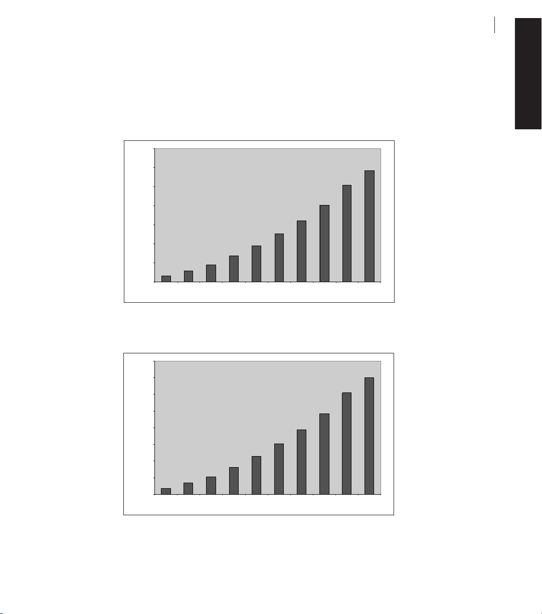
Controller Output Graphs
Output power at each set point with specified load resistance (per IEC 60601-2-2, subclause 6.8.3) is given in the
graphs below:
Output Power vs. Set Point at 300 Ohms Resistive Load, Tan Patient Cable Receptacle
Output Power vs. Set Point at 250 Ohms Resistive Load, Black Patient Cable Receptacle
0
50
100
150
200
250
300
350
400
C 1 2 3 4 5 6 7 8 9
Set Point
Power, Watts (rms)
0
50
100
150
200
250
300
350
C 1 2 3 4 5 6 7 8 9
Set Point
Power, Watts (rms)
Page 28

The output power (at full and half settings) versus load resistance (per IEC 60601-2-2, subclause 6.8.3) is given in
the graphs belows:
Output Power vs. Load Resistance, Tan Patient Cable Receptacle
Output Power vs. Load Resistance, Black Patient Cable Receptacle
Power, Watts (rms)
0
50
100
150
200
250
300
350
400
450
0 200 400 600 800 1000 1200
Load Resistance (Ohms)
Full Power
Half Power
Power, Watts (rms)
0
50
100
150
200
250
300
350
400
0 200 400 600 800 1000 1200
Load Resistance (Ohms)
Full Power
Half Power
26
ArthroCare®Atlas™ System
User’s Manual
Page 29

27
ArthroCare®Atlas™ System
User’s Manual
ENGLISH
The open circuit voltage for each set point is given in the graphs below:
Output Voltage vs. Set Point, Tan Patient Cable Receptacle
Output Voltage vs. Set point , Black Patient Cable Receptacle
0
50
100
150
200
250
300
350
C 1 2 3 4 5 6 7 8 9
Set Point
Output Voltage (Vrms)
0
50
100
150
200
250
300
350
C 1 2 3 4 5 6 7 8 9
Set Point
Output Voltage (Vrms)
Page 30

Controller Classification and Safety Verification
Classification
According to IEC 60601-2-2, Specification for High Frequency Surgical Equipment, the Controller is classified as follows:
•Type of protection against electrical shock:
Class I equipment.
• Degree of protection against electrical shock:
Defibrillation proof, type BF (Isolating/floating).
• Degree of protection against harmful ingress of water:
- Controller meets requirements of IEC 60601-2-2, subclause 44.6.
- Foot Control meets requirements of IEC 60601-2-2, subclause 44.6, watertight construction (IPX8).
• Equipment not suitable for use in the presence of a flammable anesthetic mixture.
• Mode of operation: capable of continuous operation.
Safety Verification
The ArthroCare Atlas System meets the requirements of IEC 601-1, IEC 60601-2-2. It is recommended that the
biomedical engineering department test the System to ensure that it meets the following leakage levels:
• Leakage current . . . . . . . . . . . . . . . . . . . . . . . . . . . . . . . . . . . . . . . . . . . . . . . . . . .≤20µA at 100-240 V~, 50/60 Hz
isolated patient connections
• Leakage current . . . . . . . . . . . . . . . . . . . . . . . . . . . . . . . . . . . . . . . . . . . . . . . . . .≤200µA at 100-240 V~, 50/60 Hz
non patient applied parts
If the System fails to meet the following specifications, please contact ArthroCare Customer Service for a return merchandise authorization.
28
ArthroCare®Atlas™ System
User’s Manual
Page 31

29
ArthroCare®Atlas™ System
User’s Manual
ENGLISH
Customer Service
Warranty Information
The ArthroCare Atlas Controller and Foot Control are warranted for one year and the warranty for the reusable
Patient Cable extends for a period of 90 days from the date of shipment to the original purchaser. Any component of
the System, which develops defects resulting from defective material or workmanship during these time periods will
be replaced or repaired without charge.
Product Complaints
All questions or concerns related to the quality, reliability and/or durability of this product should be directed to
Customer Service or an authorized ArthroCare representative. Please contact Customer Service for an authorized
ArthroCare representative for a return authorization.
Manufacturer
ArthroCare Corporation
Sunnyvale, CA U.S.A.
Toll Free: (800) 797-6520 (Customer Service)
www.arthrocare.com
Manufactured By
ArthroCare Corporation
Sunnyvale, CA U.S.A
ArthroCare Costa Rica
La Aurora Heredia, Costa Rica
Authorized European Representative
ArthroCare Europe AB
Stockholm, Sweden
+46 8 442 72 30
Page 32

Symbols Key
See Instructions for Use
Date of Manufacture
Coagulation
Ablation
Wand Connected
Foot Control/Hand Control Connected
Defibrillator- Proof Type BF Equipment
Fuse Rating
Non-Ionizing Radiation
Equipotential Ground
Tone Volume Control
Fragile, Handle with Care
Temperature Limitations
Keep Dry
CE mark and Identification number of Notified Body. The product meets the essential requirements of
Medical Device Directive (93/42/EEC).
The ArthroCare Atlas System is covered by the following U.S. Patents: 5,697,909; 5,679,281; 5,697,536; 5,697,882;
5,683,366; 5,681,282; 5,766,153; 5,810,764; 5,843,019; 5,871,469. Additional patents issued and pending.
ArthroCare and Atlas are registered trademarks or trademarks of ArthroCare Corporation.
CAUTION: Federal (U.S.A.) law restricts this device to sale by or on the order of a physician.
30
ArthroCare®Atlas™ System
User’s Manual
Page 33

31
ArthroCare®Atlas™ System
Manuel de l’opérateur
FRANÇAIS
Système Atlas™ ArthroCare
®
Manuel de l’opérateur
Page 34

32
ArthroCare®Atlas™ System
Manuel de l’opérateur
Page 35

33
ArthroCare®Atlas™ System
Manuel de l’opérateur
FRANÇAIS
Cet équipement a été testé et déclaré compatible avec les limites imposées pour les dispositifs médicaux conformément à la norme IEC 60601-1-2:1994. Ces limites visent à offrir une protection raisonnable vis-à-vis des interférences nocives au sein d’une installation médicale classique. Cet équipement génère, utilise et est susceptible
d’émettre de l’énergie haute fréquence et, s’il n’est pas installé et utilisé conformément aux instructions, risque de
produire des interférences nocives pour les autres appareils se trouvant à proximité. Si cet équipement produit des
interférences nocives pour d’autres appareils, ce que l’on peut vérifier en mettant l’équipement hors tension, puis en
le remettant sous tension, l’opérateur est invité à essayer de remédier à ces interférences en prenant une ou
plusieurs des mesures suivantes :
• réorienter ou déplacer l’appareil récepteur ;
• augmenter la distance entre l’équipement concerné et le contrôleur ;
• raccorder l’équipement concerné à une prise de courant ou à un circuit différent de celui auquel est connecté le
contrôleur ou
• consulter le fabricant ou le technicien de maintenance pour obtenir une assistance.
Page 36

34
ArthroCare®Atlas™ System
Manuel de l’opérateur
Page 37

ArthroCare®Atlas™ System
Manuel de l’opérateur
FRANÇAIS
35
Table des matières
Description, indications et contre-indications . . . . . . . . . . . . . . . . . . . . . . . . . . . . . . . . . . . . . . . . . . . . . . . . . . . .37
Description . . . . . . . . . . . . . . . . . . . . . . . . . . . . . . . . . . . . . . . . . . . . . . . . . . . . . . . . . . . . . . . . . . . . . . . . . . . . . . . . .37
Indications . . . . . . . . . . . . . . . . . . . . . . . . . . . . . . . . . . . . . . . . . . . . . . . . . . . . . . . . . . . . . . . . . . . . . . . . . . . . . . . . .37
Contre-indications . . . . . . . . . . . . . . . . . . . . . . . . . . . . . . . . . . . . . . . . . . . . . . . . . . . . . . . . . . . . . . . . . . . . . . . . . . .37
Présentation du système . . . . . . . . . . . . . . . . . . . . . . . . . . . . . . . . . . . . . . . . . . . . . . . . . . . . . . . . . . . . . . . . . . . . .38
Schéma de connexion . . . . . . . . . . . . . . . . . . . . . . . . . . . . . . . . . . . . . . . . . . . . . . . . . . . . . . . . . . . . . . . . . . . . . . . .38
Principe de fonctionnement . . . . . . . . . . . . . . . . . . . . . . . . . . . . . . . . . . . . . . . . . . . . . . . . . . . . . . . . . . . . . . . . . .39
Mises en garde, précautions et effets secondaires indésirables . . . . . . . . . . . . . . . . . . . . . . . . . . . . . . . . . . . . .40
Mises en garde . . . . . . . . . . . . . . . . . . . . . . . . . . . . . . . . . . . . . . . . . . . . . . . . . . . . . . . . . . . . . . . . . . . . . . . . . . . . .40
Précautions . . . . . . . . . . . . . . . . . . . . . . . . . . . . . . . . . . . . . . . . . . . . . . . . . . . . . . . . . . . . . . . . . . . . . . . . . . . . . . . .40
Effets secondaires indésirables . . . . . . . . . . . . . . . . . . . . . . . . . . . . . . . . . . . . . . . . . . . . . . . . . . . . . . . . . . . . . . . . .41
Commandes, indicateurs et alarmes . . . . . . . . . . . . . . . . . . . . . . . . . . . . . . . . . . . . . . . . . . . . . . . . . . . . . . . . . . .42
Commandes et indicateurs . . . . . . . . . . . . . . . . . . . . . . . . . . . . . . . . . . . . . . . . . . . . . . . . . . . . . . . . . . . . . . . . . . . . .42
Alarmes . . . . . . . . . . . . . . . . . . . . . . . . . . . . . . . . . . . . . . . . . . . . . . . . . . . . . . . . . . . . . . . . . . . . . . . . . . . . . . . . . . .43
Schéma des commandes, indicateurs et alarmes . . . . . . . . . . . . . . . . . . . . . . . . . . . . . . . . . . . . . . . . . . . . . . . . . . .44
Déballage, assemblage et vérification du système . . . . . . . . . . . . . . . . . . . . . . . . . . . . . . . . . . . . . . . . . . . . . . . .45
Déballage . . . . . . . . . . . . . . . . . . . . . . . . . . . . . . . . . . . . . . . . . . . . . . . . . . . . . . . . . . . . . . . . . . . . . . . . . . . . . . . . . .45
Assemblage et vérification du système . . . . . . . . . . . . . . . . . . . . . . . . . . . . . . . . . . . . . . . . . . . . . . . . . . . . . . . . . . .45
Mode d’emploi . . . . . . . . . . . . . . . . . . . . . . . . . . . . . . . . . . . . . . . . . . . . . . . . . . . . . . . . . . . . . . . . . . . . . . . . . . . . .46
Formation requise de l’opérateur . . . . . . . . . . . . . . . . . . . . . . . . . . . . . . . . . . . . . . . . . . . . . . . . . . . . . . . . . . . . . . . .46
Fonctionnement général du système . . . . . . . . . . . . . . . . . . . . . . . . . . . . . . . . . . . . . . . . . . . . . . . . . . . . . . . . . . . . .46
Tensions de sortie . . . . . . . . . . . . . . . . . . . . . . . . . . . . . . . . . . . . . . . . . . . . . . . . . . . . . . . . . . . . . . . . . . . . . . . . . . .47
Préparation et entretien du système . . . . . . . . . . . . . . . . . . . . . . . . . . . . . . . . . . . . . . . . . . . . . . . . . . . . . . . . . . .48
Préparation du système . . . . . . . . . . . . . . . . . . . . . . . . . . . . . . . . . . . . . . . . . . . . . . . . . . . . . . . . . . . . . . . . . . . . . . .48
Sélection de Wand . . . . . . . . . . . . . . . . . . . . . . . . . . . . . . . . . . . . . . . . . . . . . . . . . . . . . . . . . . . . . . . . . . . . . . . . . . .49
Mise hors tension du système . . . . . . . . . . . . . . . . . . . . . . . . . . . . . . . . . . . . . . . . . . . . . . . . . . . . . . . . . . . . . . . . . .49
Stockage et transport du système . . . . . . . . . . . . . . . . . . . . . . . . . . . . . . . . . . . . . . . . . . . . . . . . . . . . . . . . . . . . . . .49
Mise au rebut de l’équipement . . . . . . . . . . . . . . . . . . . . . . . . . . . . . . . . . . . . . . . . . . . . . . . . . . . . . . . . . . . . . . . . . .49
Page 38

36
ArthroCare®Atlas™ System
Manuel de l’opérateur
Nettoyage et stérilisation . . . . . . . . . . . . . . . . . . . . . . . . . . . . . . . . . . . . . . . . . . . . . . . . . . . . . . . . . . . . . . . . . . . .50
Contrôleur . . . . . . . . . . . . . . . . . . . . . . . . . . . . . . . . . . . . . . . . . . . . . . . . . . . . . . . . . . . . . . . . . . . . . . . . . . . . . . . . .50
Commande à pédale . . . . . . . . . . . . . . . . . . . . . . . . . . . . . . . . . . . . . . . . . . . . . . . . . . . . . . . . . . . . . . . . . . . . . . . . .50
Wand . . . . . . . . . . . . . . . . . . . . . . . . . . . . . . . . . . . . . . . . . . . . . . . . . . . . . . . . . . . . . . . . . . . . . . . . . . . . . . . . . . . . .51
Câble-patient . . . . . . . . . . . . . . . . . . . . . . . . . . . . . . . . . . . . . . . . . . . . . . . . . . . . . . . . . . . . . . . . . . . . . . . . . . . . . . .51
Entretien et dépannage . . . . . . . . . . . . . . . . . . . . . . . . . . . . . . . . . . . . . . . . . . . . . . . . . . . . . . . . . . . . . . . . . . . . . .52
Entretien . . . . . . . . . . . . . . . . . . . . . . . . . . . . . . . . . . . . . . . . . . . . . . . . . . . . . . . . . . . . . . . . . . . . . . . . . . . . . . . . . . .52
Remplacement des fusibles . . . . . . . . . . . . . . . . . . . . . . . . . . . . . . . . . . . . . . . . . . . . . . . . . . . . . . . . . . . . . . . . . . . .52
Guide de dépannage . . . . . . . . . . . . . . . . . . . . . . . . . . . . . . . . . . . . . . . . . . . . . . . . . . . . . . . . . . . . . . . . . . . . . . . . .52
Spécifications du produit . . . . . . . . . . . . . . . . . . . . . . . . . . . . . . . . . . . . . . . . . . . . . . . . . . . . . . . . . . . . . . . . . . . .54
Spécifications techniques . . . . . . . . . . . . . . . . . . . . . . . . . . . . . . . . . . . . . . . . . . . . . . . . . . . . . . . . . . . . . . . . . . . . . .54
Graphiques de sortie du contrôleur . . . . . . . . . . . . . . . . . . . . . . . . . . . . . . . . . . . . . . . . . . . . . . . . . . . . . . . . . . . . . .55
Classification et vérification de sécurité du contrôleur . . . . . . . . . . . . . . . . . . . . . . . . . . . . . . . . . . . . . . . . . . . .58
Classification . . . . . . . . . . . . . . . . . . . . . . . . . . . . . . . . . . . . . . . . . . . . . . . . . . . . . . . . . . . . . . . . . . . . . . . . . . . . . . .58
Vérification de sécurité . . . . . . . . . . . . . . . . . . . . . . . . . . . . . . . . . . . . . . . . . . . . . . . . . . . . . . . . . . . . . . . . . . . . . . . .58
Service clientèle . . . . . . . . . . . . . . . . . . . . . . . . . . . . . . . . . . . . . . . . . . . . . . . . . . . . . . . . . . . . . . . . . . . . . . . . . . . .59
Informations sur la garantie . . . . . . . . . . . . . . . . . . . . . . . . . . . . . . . . . . . . . . . . . . . . . . . . . . . . . . . . . . . . . . . . . . . .59
Réclamations relatives au produit . . . . . . . . . . . . . . . . . . . . . . . . . . . . . . . . . . . . . . . . . . . . . . . . . . . . . . . . . . . . . . .59
Légende des symboles . . . . . . . . . . . . . . . . . . . . . . . . . . . . . . . . . . . . . . . . . . . . . . . . . . . . . . . . . . . . . . . . . . . . . .60
Page 39

ArthroCare®Atlas™ System
Manuel de l’opérateur
FRANÇAIS
37
Description, indications et contre-indications
Description
L’appareil Atlas™ ArthroCare®est un système électrochirurgical bipolaire haute fréquence (HF) conçu pour être utilisé
dans le cadre des procédures arthroscopiques et orthopédiques. Le système comprend les composants suivants :
1) un contrôleur électrochirurgical haute fréquence,
2) un cordon d’alimentation réutilisable, non stérile,
3) une commande à pédale réutilisable, non stérile,
4) un câble-patient réutilisable, non stérile et
5) un Wand ArthroWand ou Microdebrider stérile jetable.
Une commande à main réutilisable non stérile est également disponible en option pour ce système.
Le contrôleur est une source de tension qui fournit de l’énergie haute fréquence (HF) nécessaire au site de traitement via un câble-patient réutilisable et un Wand stérile ou un Wand avec câble intégré, dispositif stérile combinant
Wand et câble.
Le câble-patient réutilisable fourni n’est pas stérile, mais il a été conçu en vue d’une stérilisation préalable à toute
utilisation.
Le Wand stérile jetable est disponible dans différentes configurations à un seul ou plusieurs embouts et est fourni
séparément. Il peut être équipé d’un élément câble intégré destiné à remplacer le câble-patient.
Le contrôleur peut être activé à l’aide d’une commande à pédale réutilisable ou d’une commande à main réutilisable
disponible en option.
Indications
Le système Atlas ArthroCare est indiqué pour la résection, l’ablation et la coagulation des tissus mous, ainsi que
pour l’hémostase des vaisseaux sanguins lors de procédures arthroscopiques ou orthopédiques.
Contre-indications
L’utilisation du système Atlas est contre-indiquée pour les procédures n’impliquant pas de solution conductrice. Ce
système est également contre-indiqué chez les patients porteurs d’un stimulateur cardiaque ou d’autres implants
électroniques sans instructions spécifiques du fabricant du stimulateur cardiaque ou de l’implant. Une liste complète
des contre-indications pour chaque procédure spécifique figure dans le mode d’emploi du Wand.
Page 40

38
ArthroCare®Atlas™ System
Manuel de l’opérateur
6
5
1. Contrôleur 9c. Connecteur de câble à fiche noire
2. Câble d’alimentation 10. Wand
3. Commande à pédale 11. Tige
4. Pédale d’activation de l’ablation 12. Électrode de retour
5. Pédale de coagulation 13. Embout d’électrode activée
6. Bouton de réglage du point de consigne 14. Tubulure d’aspiration (en option suivant le type de Wand)
7. Câble-patient 15. Tubulure d’irrigation (en option suivant le type de Wand)
8. Connecteur du contrôleur 16. Poignée
9a. Connecteur du câble-patient 17. Wand avec câble intégré
9b. Connecteur de câble à fiche grise
Présentation du système
Schéma de connexion
Page 41

ArthroCare®Atlas™ System
Manuel de l’opérateur
FRANÇAIS
Principe de fonctionnement
Le contrôleur Atlas ArthroCare est conçu pour fournir l’énergie haute fréquence (HF) nécessaire aux éléments
d’électrode situés à l’extrémité distale des Wands stériles à usage unique. Le courant circule de l’élément d’électrode active à l’élément d’électrode de retour intégré, ces deux éléments ou pôles étant situés sur le Wand proprement dit dans une configuration bipolaire, délivrant ainsi un champ énergétique localisé. Le résultat de cette disposition est une libération d’énergie contrôlée avec un minimum de dommages aux tissus collatéraux.
Le système Atlas ArthroCare agit en faisant passer l’énergie HF au travers d’une solution conductrice (par exemple,
une solution physiologique salée ou une solution de lactate de Ringer) à proximité immédiate ou en contact direct
avec les tissus à traiter. La solution conductrice forme une fine couche entre les éléments de l’électrode active et de
l’électrode de retour. En mode ablation, lorsqu’une quantité suffisante d’énergie est appliquée, la solution conductrice se transforme en une couche de vapeur (plasma) contenant des particules chargées sous tension. Lorsque les
particules à haute teneur en énergie viennent en contact avec les tissus, elles provoquent leur désintégration par
dissociation moléculaire.
Ce mode de fonctionnement résulte en des températures au site de traitement relativement basses par comparaison
avec les systèmes électrochirurgicaux conventionnels ou les systèmes HF unipolaires, ce qui engendre des dommages thermiques collatéraux limités aux tissus environnants non traités.
Le système peut également fonctionner lorsqu’une plus faible tension est appliquée entre l’électrode active et l’électrode de retour. Dans ce cas, le champ électrique est inférieur au seuil nécessaire à la formation d’une couche de
plasma, et un chauffage des tissus résistifs se produit. Ce mode est utile lorsque l’on recherche un effet thermique
plus important, par exemple pour la coagulation de vaisseaux sanguins. Le réglage de tension approprié dépend du
type de Wand utilisé, du type de tissu et de l’effet tissulaire souhaité.
39
Page 42

40
ArthroCare®Atlas™ System
Manuel de l’opérateur
Mises en garde, précautions et effets secondaires indésirables
On trouvera ci-après une liste de mises en garde et précautions qui s’appliquent au fonctionnement général du système Atlas ArthroCare. Pour des mises en garde et précautions spécifiques, se reporter au mode d’emploi du Wand
et du câble-patient.
MISES EN GARDE
•Tout manquement aux instructions applicables pourrait entraîner des conséquences chirurgicales graves.
• Danger d’incendie : NE PAS placer d’accessoires actifs à proximité de matériaux inflammables (tels que gaze ou
champs opératoires) ou à leur contact.
• Des accessoires d’électrochirurgie sous tension ou encore chauds après usage peuvent provoquer un incendie.
• Les extrémités des accessoires peuvent rester suffisamment chaudes pour provoquer des brûlures même après
la mise hors tension.
• Une activation ou un mouvement intempestifs des Wands hors du champ de vision peuvent provoquer des
blessures sur le patient.
• Un courant d’électrochirurgie conduit par d’autres instruments ou par des objets conducteurs peut entraîner des
brûlures sur le patient ou sur le médecin.
• Un courant électrochirurgical peut être généré dans des objets conducteurs par contact direct avec l’électrode
active ou en cas de proximité immédiate de l’électrode active ou de l’électrode de retour avec un objet conducteur.
• Si un chauffage excessif ou l’application de forces physiques endommagent l’extrémité du Wand, des fragments
de corps étrangers peuvent se former et nécessiter une intervention chirurgicale étendue en vue de leur retrait.
• NE PAS utiliser le système Atlas ArthroCare avec des supports non conducteurs (ex. : eau stérilisée, dextrose,
air, gaz, glycine, etc.). Utiliser uniquement des supports conducteurs, par exemple une solution physiologique
salée ou une solution de lactate de Ringer.
• Risque de choc électrique : NE PAS brancher d’accessoires humides sur le contrôleur.
• Un dysfonctionnement du contrôleur risque d’entraîner une augmentation accidentelle de la puissance de sortie.
PRÉCAUTIONS
•Avant la première utilisation, s’assurer que toutes les notices jointes à l’emballage, y compris les mises en garde
et précautions et le mode d’emploi, ont été lues et comprises.
• La pratique sûre et efficace de l’électrochirurgie ne dépend pas uniquement de la conception du matériel, mais,
dans une grande mesure, de facteurs sous le contrôle de l’utilisateur. Seules les personnes bénéficiant d’une formation appropriée et d’une bonne maîtrise de la chirurgie orthopédique peuvent pratiquer des interventions avec
le système Atlas ArthroCare.
• Consulter la littérature médicale consacrée aux techniques, aux complications et aux risques avant de pratiquer
toute intervention.
• Déceler chez les patients tout facteur de risque médical qui pourrait être aggravé par le stress opératoire.
• Une compréhension approfondie des principes et techniques inhérents aux procédures électrochirurgicales est
essentielle si l’on souhaite prévenir tout risque de choc électrique et de brûlures pour le patient et le personnel
médical et éviter d’endommager l’appareil, ainsi que les autres instruments médicaux. Pour cela, s’assurer également de l’intégrité du dispositif d’isolation ou de mise à la terre du contrôleur.
• En cas d’utilisation conjointe d’instruments et accessoires de différents fabricants, vérifier leur compatibilité avant
le début de l’intervention.
• Lorsqu’il n’est pas utilisé, veiller à éloigner le Wand du site chirurgical et à ce qu’il se trouve à distance de tout
objet métallique. Les Wands doivent rester à l’écart des autres équipements d’électrochirurgie de manière à éviter
Page 43

ArthroCare®Atlas™ System
Manuel de l’opérateur
FRANÇAIS
41
tout couplage électrique intempestif entre dispositifs. Toute activation accidentelle peut occasionner des blessures
chez le patient et/ou l’opérateur ou encore, endommager l’équipement.
• NE PAS enrouler le câble-patient autour d’objets métalliques. Cela pourrait créer des courants induits suscepti-
bles d’entraîner des chocs électriques, des incendies ou des blessures du patient ou du personnel chirurgical.
• N’utiliser les extrémités du Wand pour sonder ou manipuler les tissus qu’avec précaution. Un contact violent entre
les extrémités du Wand et les tissus ou d’autres instruments peut endommager l’instrument.
• NE PAS utiliser le Wand comme levier pour élargir le site chirurgical ou accéder aux tissus.
• ÉVITER tout contact de liquide avec les connecteurs électriques du Wand, du contrôleur ou des câbles lors de l’u-
tilisation.
• Opter pour le réglage de puissance minimal du contrôleur nécessaire pour obtenir l’effet voulu.
• S’assurer de l’activation du Wand si le réglage de puissance du contrôleur choisi ne correspond pas aux réglages
par défaut définis.
• ÉVITER tout contact du patient avec des objets métalliques au sol, tels que le châssis de la table chirurgicale ou
une table d’instruments, pour empêcher tout risque de choc électrique. L’utilisation de plaques de mise à la terre
est vivement déconseillée.
• ÉVITER tout contact entre des objets métalliques et un Wand activé.
•Toujours respecter les consignes de sécurité anti-incendie. Des étincelles et un réchauffement associés à l’électrochirurgie peuvent constituer un foyer d’incendie.
• NE PAS utiliser de produits inflammables pour le nettoyage et la désinfection du contrôleur ou des câbles.
• Comme pour toute unité électrochirurgicale, du courant haute fréquence peut circuler dans les électrodes et les
câbles. Positionner les câbles de façon à éviter tout contact avec le patient ou d’autres conducteurs électriques.
• Un dispositif électrochirurgical haute fréquence (HF), tel que le système Atlas ArthroCare, peut nuire au fonctionnement d’autres appareils électroniques.
• Les électrodes doivent rester à l’écart des autres équipements d’électrochirurgie de manière à éviter tout couplage électrique intempestif entre dispositifs.
• Il convient de placer les électrodes de surveillance aussi loin que possible des électrodes chirurgicales lorsqu’un
dispositif chirurgical HF et un appareil de monitorage physiologique sont utilisés simultanément sur le même
patient. Les électrodes de surveillance sont déconseillées.
• Il est recommandé d’utiliser des appareils de monitorage dotés de dispositifs limiteurs de courant haute
fréquence.
• NE PAS retirer le capot du contrôleur. Confier l’entretien à des techniciens qualifiés.
• NE PAS obstruer le ventilateur de sortie (qui se trouve à l’arrière du contrôleur).
• NE PAS toucher le ventilateur et/ou le haut-parleur du contrôleur en même temps que le patient.
•Avant chaque utilisation, s’assurer que tous les voyants lumineux et signaux sonores du contrôleur fonctionnent.
S’assurer que le connecteur du cordon d’alimentation est correctement raccordé au connecteur du contrôleur.
• Pour éviter tout risque d’incendie, remplacer les fusibles du contrôleur uniquement par des fusibles de même type
et de même capacité.
• Le système Atlas ArthroCare est conçu pour fonctionner en tant qu’unité. Utiliser exclusivement des accessoires
fournis par ArthroCare.
EFFETS SECONDAIRES INDÉSIRABLES
Lors d’une procédure électrochirurgicale, les tissus environnants peuvent subir des lésions d’origine iatrogène.
Page 44

42
ArthroCare®Atlas™ System
Manuel de l’opérateur
Commandes, indicateurs et alarmes
Commandes et indicateurs
Le contrôleur Atlas comprend les commandes et indicateurs suivants :
PANNEAU AVANT
1. Commutateur de marche/arrêt
Ce commutateur à bascule sert à mettre le contrôleur sous tension ou hors tension. Lorsque le contrôleur est
sous tension, des chiffres verts sont visibles dans la fenêtre d’affichage du réglage du point de consigne. Cet
affichage peut persister encore 5 secondes après la mise hors tension.
2. Indicateur d’avertissement
Ce voyant lumineux rouge s’allume en cas de dysfonctionnement ou de panne spécifique du contrôleur.
3. Indicateur de connexion de la commande à pédale/main
Lorsque la commande à pédale/main est correctement raccordée, le voyant lumineux de connexion de la commande à pédale/main s’allume (en vert).
4. Indicateur d’activation de la coagulation
Un indicateur bleu s’allume lorsqu’une pression est appliquée sur la pédale de commande de coagulation à
pédale/main, alors qu’un Wand est raccordé à l’appareil.
5. Indicateur de connexion de Wand
Lorsque le câble-patient et le Wand sont correctement raccordés, le voyant lumineux de connexion de Wand
s’allume (en vert). Avec le Wand à câble intégré, le voyant lumineux s’allume lorsque l’extrémité du connecteur
du câble du Wand est correctement enfichée sur le contrôleur.
6. Réglage du point de consigne
Des touches fléchées d’augmentation et de réduction permettent de régler la tension de sortie pour l’ablation.
Cette tension de sortie peut également être réglée au moyen du bouton de réglage du point de consigne pour
l’ablation qui se trouve sur la commande à pédale/main. Se reporter à la section Mode d’emploi de ce manuel
pour connaître les valeurs de tension correspondant à chaque réglage.
7. Fenêtre d’affichage du point de consigne
Cette fenêtre indique le réglage de tension en sortie. Une valeur nominale s’affiche automatiquement dans cette
fenêtre lorsque l’appareil est mis sous tension alors qu’un Wand y est raccordé ou lorsqu’un nouveau Wand est
connecté. Lorsque le contrôleur est sous tension et avant le raccordement d’un Wand, cette fenêtre affiche 0.
8. Indicateur d’activation de l’ablation
Un indicateur jaune s’allume lorsqu’une pression est appliquée sur la commande de coagulation à pédale/main,
alors qu’un Wand est raccordé à l’appareil.
Page 45

ArthroCare®Atlas™ System
Manuel de l’opérateur
FRANÇAIS
43
9. Connecteur de la commande à pédale/main
Le câble de la commande à pédale/main se raccorde au connecteur jaune situé à l’avant du contrôleur.
10. Symbole d’équipement de type BF à l’épreuve des défibrillateurs
Cet équipement bénéficie d’un niveau de protection contre les chocs électriques à des pièces appliquées de
type BF tel que défini par la norme IEC 601-1 ; il possède également une pièce appliquée de type F capable de
résister aux effets de la décharge produite par un défibrillateur.
11. Connecteur de câble noir
Le connecteur de câble à bague noire peut être raccordé aux Wands à câble intégré dotés d’une fiche noire.
12. Connecteur de câble jaune
Le connecteur de câble à bague jaune peut être raccordé au câble-patient réutilisable et aux Wands à câble
intégré dotés d’une fiche grise.
13. Panneau coulissant
Ce panneau coulisse de gauche à droite et permet d’accéder au connecteur de câble noir ou jaune.
PANNEAU ARRIÈRE
14. Contrôle du volume sonore
Le contrôle du volume sonore sert à régler le volume sonore. Pour augmenter le volume, tourner le bouton dans le sens
des aiguilles d’une montre. Pour réduire le volume, tourner le bouton dans le sens contraire des aiguilles d’une montre.
15. Symbole de rayonnement non ionisant
Ce symbole indique que cet équipement émet intentionnellement de l’énergie HF lorsqu’il est activé.
16. Symbole de capacité des fusibles
Ce symbole indique que seuls des fusibles de capacité appropriée peuvent être utilisés. Consulter la plaque signalétique qui se trouve à l’arrière du contrôleur pour connaître la capacité des fusibles. Se reporter à la section
Entretien et dépannage de ce manuel pour des instructions concernant le remplacement des fusibles.
17. Prise pour cordon d’alimentation/porte-fusibles
Le cordon d’alimentation du contrôleur se branche à cette prise. Le porte-fusibles se trouve derrière la prise.
18. Symbole de terre équipotentielle
Ce symbole identifie le conducteur utilisé pour raccorder l’équipement à la terre.
19. Label CE - Symbole de certification européenne
Ce symbole indique la conformité avec la directive de la Commission européenne relative aux dispositifs médicaux (93/42/CEE).
20. Symbole Attention
Ce symbole rappelle à l’utilisateur qu’il lui faut lire et comprendre ce manuel et les instructions qui l’accompagnent avant d’utiliser l’équipement.
21. Entrée auxiliaire
Réservée au fabricant.
Alarmes
1. Double tonalité intermittente : alarme de limite de courant ou de surcharge
2. Monotonique intermittente : alarme de problème de connexion (câble-patient, Wand, Wand avec câble
intégré, dépassement de température, suralimentation)
Page 46

44
ArthroCare®Atlas™ System
Manuel de l’opérateur
Schéma des commandes, indicateurs et alarmes
Page 47

ArthroCare®Atlas™ System
Manuel de l’opérateur
FRANÇAIS
45
Déballage, assemblage et vérification du système
Déballage
Contrôler que tous les éléments ont été livrés et qu’ils ne sont pas endommagés. Les éventuels dommages doivent
être signalés immédiatement au Service clientèle. Ranger toutes les boîtes et matériaux d’emballage car ils devront
être réutilisés s’il s’avère nécessaire de retourner l’équipement.
Assemblage et vérification du système
1. Raccorder le cordon d’alimentation à la prise située sur le panneau arrière du contrôleur. Raccorder l’autre
extrémité du cordon d’alimentation à une prise de courant. S’il est nécessaire d’utiliser un autre cordon d’alimentation que celui livré avec le contrôleur, ce cordon d’alimentation supplémentaire doit être conforme aux normes
électriques en vigueur et convenir à l’utilisation en milieu hospitalier.
2. Mettre le commutateur de marche/arrêt qui se trouve sur le panneau avant du contrôleur sur la position “ Marche “
(I). La fenêtre d’affichage du réglage du point de consigne doit indiquer un réglage de “ 0 “. Tous les autres
voyants lumineux doivent être éteints.
3. Fixer le câble de la commande à pédale ou à main au connecteur jaune situé à l’avant du contrôleur. Le voyant
lumineux de connexion de la commande à pédale/main sur le panneau avant du contrôleur doit s’allumer.
4. Pour une ablation, appuyer sur la commande à pédale ou à main de coagulation. Le voyant lumineux rouge
d’avertissement situé sur le panneau avant du contrôleur doit s’allumer et le contrôleur doit émettre une alarme
monotonique intermittente. Le voyant lumineux jaune d’activation de l’ablation situé sur le panneau avant doit
être éteint.
5. Raccorder le câble-patient au connecteur de câble de gauche situé en bas et à gauche sur le contrôleur. Les
voyants lumineux du câble-patient et du Wand ne doivent pas s’allumer. Aucune alarme ne doit se déclencher.
6. Raccorder un ArthroWand au câble-patient. Le voyant lumineux de connexion de Wand doit s’allumer.
ATTENTION : ÉVITER tout contact entre des objets métalliques et un Wand activé.
ATTENTION : NE PAS placer d’accessoires actifs à proximité de matériaux inflammables (tels que gaze ou
champs opératoires) ou à leur contact.
ATTENTION : Des accessoires d’électrochirurgie sous tension ou encore chauds après usage peuvent provoquer
un incendie.
ATTENTION : Les extrémités des accessoires peuvent rester suffisamment chaudes pour provoquer des brûlures
même après la mise hors tension.
ATTENTION : Un courant d’électrochirurgie conduit par d’autres instruments ou par des objets conducteurs peut
entraîner des brûlures sur le patient ou sur le médecin.
7. En veillant à ne pas toucher l’extrémité du Wand, appuyer sur la pédale d’ablation (jaune) de la commande à
pédale. Le voyant jaune d’activation de l’ablation doit s’allumer. Si le contrôleur ne fonctionne pas de la manière
décrite ci-dessus, contacter immédiatement le Service clientèle.
Page 48

Mode d’emploi
Formation requise de l’opérateur
L’opérateur doit avoir une bonne expérience des techniques électrochirurgicales. Il lui est conseillé de se tenir au
courant des progrès dans le domaine des procédures orthopédiques. Une formation supplémentaire à l’utilisation du
système Atlas ArthroCare assurée par un représentant d’ArthroCare est conseillée.
Fonctionnement général du système
L’activation des Wands s’effectue via la commande à pédale ou la commande à main. La commande à pédale et la
commande à main sont munies de trois fonctions, comme décrit ci-dessous :
Activation de l’ablation
Une pression sur la fonction d’activation de l’ablation sélectionne le mode normal d’ablation du contrôleur et active le Wand.
Activation de la coagulation
Une pression sur la fonction d’activation de la coagulation sélectionne le mode coagulation prédéfini
du contrôleur et active également le Wand pour l’hémostase de vaisseaux sanguins.
Réglage du point de consigne pour l’ablation
Une pression sur la fonction de réglage du point de consigne pour l’ablation ajuste la tension
délivrée par le contrôleur pour l’ablation. Chaque fois que l’on actionne la fonction de réglage du
point de consigne pour l’ablation, le niveau de tension pour l’ablation augmente d’un point jusqu’au
point de consigne maximal pour chaque type de Wand. Lorsque le niveau maximal pour le Wand
connecté est atteint, le système revient au point de consigne un (1).
REMARQUE : la commande à pédale et la commande à main ne peuvent pas être utilisées simultanément.
46
ArthroCare®Atlas™ System
Manuel de l’opérateur
Page 49

ArthroCare®Atlas™ System
Manuel de l’opérateur
FRANÇAIS
Tensions de sortie
Les tensions de sortie correspondent aux affichages de point de consigne, tels qu’indiqués dans le tableau ci-dessous. Suivant le
type de câble-patient utilisé, l’affichage correspond à la tension de sortie en circuit ouvert, comme indiqué ci-après :
Connecteur de câble-patient jaune Connecteur de câble-patient noir
Lors de la première mise sous tension du contrôleur alors qu’aucun Wand n’y est connecté, la valeur de point de
consigne “ 0 “ apparaît sur l’afficheur du panneau avant en tant que réglage par défaut. Si un Wand est connecté à
ou après la mise sous tension du contrôleur, ce dernier règle l’affichage et la tension de sortie sur les valeurs nominales. Ces valeurs fournissent généralement les meilleurs résultats dans la plupart des cas.
REMARQUE : Si un point de consigne est sélectionné en dehors de la plage de réglage par défaut (comprise entre
le point de consigne initial et le point de consigne maximum), il est nécessaire de s’assurer de l’activation appropriée du Wand.
Lorsqu’un Wand a été correctement raccordé, il est possible d’augmenter ou de diminuer le réglage de la tension en
appuyant sur les touches de réglage du niveau de tension situées sur le panneau avant. Le niveau d’ablation peut
également être réglé en appuyant sur la fonction de réglage du point de consigne de l’ablation qui se trouve sur la
commande à pédale ou sur la commande à main. Les réglages de tension pour l’ablation peuvent être ajustés à
des niveaux qui se situent dans la plage de valeurs autorisée, en fonction de la tension maximale admise par le
Wand utilisé.
Affichage Tension de sortie
(Vrms ±10 %)
1 100
2 129
3 158
4 186
5 215
6 244
7 273
8 301
9 330
C70
47
Affichage Tension de sortie
(Vrms ±10 %)
1 100
2 125
3 150
4 175
5 200
6 225
7 250
8 275
9 300
C70
Page 50

Préparation et entretien du système
Préparation du système
1. Avant chaque utilisation, inspecter le système Atlas ArthroCare en recherchant d'éventuels dommages au niveau
du boîtier du contrôleur et des câbles.
2. Insérer l'extrémité connecteur du câble d'alimentation dans la prise pour câble d'alimentation située à l'arrière du
contrôleur. Insérer l'extrémité de la prise du câble d'alimentation dans une prise de courant correctement raccordée à la terre. Placer le contrôleur de telle manière que le ventilateur de sortie qui se trouve à l'arrière du
contrôleur ne soit pas obstrué et dirigé vers le patient.
3. Mettre le commutateur de marche/arrêt qui se trouve sur le panneau avant du contrôleur sur la position
" Marche " (I). Tension de sortie. La fenêtre d'affichage du réglage de tension de sortie doit indiquer un réglage
de " 0 ". Tous les autres voyants lumineux doivent être éteints.
4. Fixer le câble de la commande à pédale ou à main au connecteur gris de la commande à pédale/main situé à
l'avant du contrôleur. Le voyant lumineux de connexion de la commande à pédale/main sur le panneau avant du
contrôleur doit s'allumer (en vert).
5. a. En cas d'utilisation du câble-patient réutilisable, s'assurer que celui-ci a été préalablement nettoyé et stérilisé
et que ses connecteurs sont secs avant tout usage. Faire glisser le panneau coulissant vers la droite et raccorder le câble-patient au connecteur jaune situé à l'avant du contrôleur. Raccorder le Wand appropriée à
l'autre extrémité du câble-patient.
REMARQUE : Si le panneau coulissant a été retiré, contacter le Service clientèle.
b. En cas d'utilisation d'un Wand avec câble intégré doté d'une fiche grise, faire glisser le panneau coulissant
vers la droite et raccorder le Wand avec câble intégré au connecteur jaune.
c. En cas d'utilisation d'un Wand avec câble intégré doté d'une fiche noire, faire glisser le panneau coulissant
vers la gauche et raccorder le Wand avec câble intégré au connecteur noir situé à l'avant du contrôleur.
REMARQUE : Pour des instructions spécifiques sur la préparation et les procédures chirurgicales, se
reporter au mode d'emploi du Wand.
6. Régler l'affichage du réglage du point de consigne au niveau voulu pour obtenir les effets souhaités.
48
ArthroCare®Atlas™ System
Manuel de l’opérateur
Page 51

ArthroCare®Atlas™ System
Manuel de l’opérateur
FRANÇAIS
49
Sélection de Wand
Sélectionner le type de Wand le plus adapté à la procédure. Le contrôleur prédéfinit des tensions nominales et
maximales pour l’ablation pour chaque type de Wand afin de garantir un fonctionnement sûr et efficace.
REMARQUE : Les valeurs de tension initiale et maximale sont des valeurs suggérées. Il convient de s’assurer sys-
tématiquement de l’activation appropriée du Wand.
Pour ajuster le réglage de la tension pour l’ablation, le Wand et le câble-patient doivent être connectés au contrôleur.
Mise hors tension du système
1. Mettre le commutateur d’alimentation sur la position “ Arrêt “. Après un bref délai (moins de 4 secondes), tous
les voyants lumineux du contrôleur et l’affichage du point de consigne s’éteignent.
2. Débrancher la tubulure d’aspiration, si nécessaire.
3. En cas d’utilisation du câble-patient réutilisable, débrancher le Wand du câble-patient, puis déconnecter le câblepatient du contrôleur. Jeter le Wand et préparer le câble-patient en vue de sa stérilisation pour une utilisation
ultérieure.
4. En cas d’utilisation d’un ArthroWand avec câble intégré, débrancher le câble du Wand du contrôleur. Ne pas
essayer de dissocier l’ArthroWand de l’élément du câble. Jeter le Wand avec câble intégré.
Stockage et transport du système
Tous les composants du système Atlas ArthroCare peuvent être stockés et transportés en toute sécurité à des températures ambiantes comprises entre -40°C et +70°C. L’humidité relative doit être comprise entre 10 et 85 %.
Mise au rebut de l’équipement
Le système Atlas ArthroCare contient des circuits imprimés électroniques. Sa mise au rebut doit être conforme à
toutes les réglementations nationales ou institutionnelles en vigueur concernant l’équipement électronique obsolète.
Procéder à la mise au rebut du Wand, du Wand avec câble intégré et du câble-patient conformément aux pratiques
institutionnelles en vigueur relatives au matériel susceptible d’être contaminé.
Page 52

50
ArthroCare®Atlas™ System
Manuel de l’opérateur
Nettoyage et stérilisation
Contrôleur
NE PAS stériliser ou immerger dans un liquide. Frotter avec un chiffon et un détergent doux, si nécessaire.
Commande à pédale
NE PAS stériliser. Nettoyer au moyen de détergents et de désinfectants conformément aux pratiques courantes.
Désinfecter à l’aide de désinfectants chimiques liquides tels que des solutions chlorées, des iodophores, de la glutaraldéhyde et du peroxyde d’hydrogène. Se conformer aux consignes du fabricant en ce qui concerne la concentration et la durée d’exposition.
Wand
Le Wand est fourni stérile et il est destiné à un usage unique. NE PAS nettoyer, restériliser ou réutiliser le
Wand car cela pourrait occasionner un dysfonctionnement ou une panne de l’appareil ou encore blesser le
patient, ce qui pourrait également exposer ce dernier à un risque de contamination infectieuse. Pour des
instructions spécifiques sur l’utilisation du Wand, se reporter au mode d’emploi associé à chaque type de Wand.
Câble-patient
Le câble-patient est fourni NON STÉRILE. Il est réutilisable s’il est nettoyé et stérilisé avant chaque usage. Veiller
à ce qu’une procédure de stérilisation à la vapeur validée et approuvée soit utilisée.
Nettoyage
•Avant de nettoyer le câble, fixer les capuchons de protection sur les connecteurs du câble-patient de façon à protéger ces derniers contre tout dommage. Ces capuchons ont été conçus pour s’adapter parfaitement aux connecteurs du câble-patient. Si les capuchons n’enserrent pas complètement les connecteurs, s’assurer que les
joints toriques en silicone se trouvent dans la rainure du connecteur du câble. Des joints toriques de rechange
sont disponibles auprès de ArthroCare. Frotter le câble-patient avec une brosse souple ou une éponge imbibée
d’une solution à base de détergent doux afin d’en retirer tous les contaminants. Rincer le câble-patient à grande
eau pour éliminer tout résidu de nettoyage. NE PAS immerger le câble-patient dans l’eau ni dans toute autre
solution. Retirer les capuchons des connecteurs du câble-patient et inspecter celui-ci pour vérifier l’absence de
coupures ou d’entailles. Si le câble-patient est endommagé, il ne doit pas être réutilisé. Stériliser le câble-patient
nettoyé selon l’une des méthodes recommandées ci-dessous :
Stérilisation à la vapeur avec mise sous vide préalable
Si le stérilisateur à vapeur avec mise sous vide préalable est équipé d’une fonction de cycle prédéfini, utiliser le
cycle “ Biens durables “. Si le stérilisateur n’intègre pas de cycle prédéfini, les paramètres suivants sont recommandés :
• Régler la température entre 132 et 133 °C.
• Régler la durée d’exposition sur 10 minutes pour les câbles-patient enroulés.
• Régler la durée d’exposition sur 4 minutes pour les câbles-patient non enroulés.
• Régler la durée de séchage sur 5 minutes minimum.
Page 53

ArthroCare®Atlas™ System
Manuel de l’opérateur
FRANÇAIS
51
Nettoyage et stérilisation (Suite)
Stérilisation à la vapeur avec déplacement d’air par gravité
Pour une stérilisation à la vapeur avec déplacement d’air par gravité, les paramètres suivants sont recommandés :
• Régler la température entre 132 et 133 °C.
• Régler la durée d’exposition sur 15 minutes pour les câbles enroulés.
• Régler la durée d’exposition sur 10 minutes pour les câbles-patient non enroulés.
• Régler la durée de séchage sur 8 minutes minimum. Ou :
• Régler la température entre 121 et 133 °C.
• Régler la durée d’exposition sur 35 minutes pour les câbles enroulés et non enroulés.
• Régler la durée de séchage sur 8 minutes minimum.
ATTENTION : Un nettoyage incorrect du câble-patient peut entraîner une stérilisation inadéquate.
ATTENTION : Les paramètres de stérilisation recommandés ne sont corrects que si le matériel de stérilisation
est entretenu et calibré de manière appropriée.
ATTENTION : Pour garantir une stérilisation adéquate, s’assurer que les capuchons de protection ne recou-
vrent pas les connecteurs du câble pendant la stérilisation.
ATTENTION : S’assurer que le câble est totalement sec avant toute utilisation. Des connecteurs humides
peuvent endommager le câble et le contrôleur.
Page 54

52
ArthroCare®Atlas™ System
Manuel de l’opérateur
Entretien et dépannage
Entretien
Le contrôleur ne contient aucune pièce pouvant être entretenue par l’utilisateur, à l’exception du remplacement des
fusibles. Il a été conçu pour délivrer des niveaux de sortie reproductibles et est calibré par une horloge à cristaux,
des tensions de références et des résistances fixes. L’appareil n’intègre AUCUN réglage interne et, grâce aux méthodes d’étalonnage intégrées, aucun contrôle annuel d’entretien n’est nécessaire. Il n’y a AUCUN logiciel incorporé
au contrôleur Atlas ArthroCare. En cas de dysfonctionnement de l’un des composants, contacter le Service clientèle
pour une autorisation de retour.
Remplacement des fusibles
Le porte-fusibles se trouve à l’arrière du contrôleur. Pour remplacer un fusible, mettre le contrôleur hors tension et
débrancher le cordon d’alimentation de la prise d’alimentation située à l’arrière du contrôleur. Après avoir attendu au
moins 10 secondes que les circuits internes se déchargent, utiliser un tournevis ou un outil similaire pour extraire le
porte-fusibles en appuyant sur les onglets de verrouillage. Remplacer les deux fusibles par des fusibles de même
type et de même capacité comme spécifié sur le panneau arrière du contrôleur. Réinsérer le porte-fusibles jusqu’à
ce que les onglets de verrouillage s’enclenchent en position. Reconnecter le cordon d’alimentation et remettre le
contrôleur sous tension. Si un fusible fond à nouveau, débrancher l’alimentation électrique du contrôleur et contacter le Service clientèle.
Guide de dépannage
En cas de problèmes avec le Système Atlas ArthroCare, se reporter au guide de dépannage ci-après pour tenter d’identifier ou de résoudre le problème avant de faire appel au Service clientèle.
• Le système ne se met pas sous tension après que l’on ait appuyé sur le commutateur d’alimentation.
S’assurer que le cordon d’alimentation est correctement connecté au contrôleur et est raccordé à une prise de
courant correctement mise à la terre. Si l’appareil est correctement connecté, contrôler si les fusibles ont fondu.
Pour remplacer les fusibles, suivre les instructions de la section Remplacement des fusibles.
• Le voyant lumineux vert de connexion de la commande à pédale/main ne s’allume pas.
S’assurer que la commande à pédale/main est correctement connectée au contrôleur et que le câble n’est ni
entaillé, ni coupé, ni usé. Ne pas utiliser la commande à pédale/main si le câble est endommagé. Si le problème
persiste, remplacer la commande à pédale/main. Si le voyant lumineux de connexion de commande à
pédale/main ne s’allume toujours pas, retourner le système pour réparation.
• Le voyant lumineux vert de connexion de Wand ne s’allume pas lorsqu’un Wand est connecté au câblepatient réutilisable.
S’assurer que le Wand est fermement raccordé au câble-patient et que le câble-patient est correctement connecté
au contrôleur. Si le problème persiste, remplacer d’abord le câble-patient et ensuite le Wand. Si le voyant
lumineux de connexion de Wand ne s’allume toujours pas, retourner le système pour réparation.
Page 55

ArthroCare®Atlas™ System
Manuel de l’opérateur
FRANÇAIS
53
Entretien et dépannage (Suite)
• Rien ne se produit lorsque l’on appuie sur l’une des fonctions d’activation du dispositif de la commande à
pédale/main.
Vérifier que les voyants lumineux de connexion de la commande à pédale/main et de connexion de Wand sont
allumés lorsque l’on appuie sur la commande à pédale/main. S’assurer que la tension a été réglée à un niveau
adéquat pour ce que l’on veut faire (généralement 1 ou plus). Vérifier que l’extrémité du Wand et la tige sont
recouvertes de solution d’irrigation conductrice. S’assurer que le Wand est fermement raccordé au câble-patient
et que le câble-patient est correctement connecté au contrôleur. Si le problème persiste, remplacer d’abord le
câble-patient et ensuite le Wand. Si le système ne fonctionne toujours pas, le retourner pour réparation.
• Le Wand ne s’active pas ; une alarme monotonique intermittente se fait entendre et un voyant lumineux
rouge d’avertissement s’allume.
Ceci indique généralement un problème de connexion. S’assurer que le Wand est fermement raccordé au câblepatient et que le câble-patient est correctement connecté au contrôleur. Vérifier toutes les connexions. Si
l’alarme continue à se faire entendre lorsque l’on appuie sur la commande à pédale ou sur la commande à main,
remplacer d’abord le câble-patient et ensuite le Wand. Si le problème persiste, retourner le système pour réparation.
• Une double tonalité d’alarme se fait entendre et un voyant lumineux rouge d’avertissement s’allume lors
de l’activation du Wand.
Il s’agit d’une fonction de sécurité du système Atlas ArthroCare et ceci peut se produire lorsque le Wand est
activé pendant une période prolongée sans être mis en contact avec les tissus. Pour réinitialiser l’appareil, retirer
le pied de la commande à pédale, si le système est connecté à une commande de ce type. Si le système est raccordé à la commande à main, relâcher le bouton de la commande. S’assurer que le Wand est bien en contact
avec le tissu cible et appuyer à nouveau sur la commande à pédale ou sur la commande à main. Si l’alarme continue à se faire entendre, remplacer d’abord le câble-patient et ensuite le Wand. Si le problème persiste, retourner le système pour réparation.
Page 56

Spécifications du produit
Spécifications techniques
Câble-patient
Longueur du câble . . . . . . . . . . . . . . . . . . . . . . . . . . . . . . . . . . . . . . . . . . . . . . . . . . . . . . . . . . . . . . . . . . . . . . . .3.3 m
Méthode de stérilisation . . . . . . . . . . . . . . . . . . . . . . . . . . . . . . . . . . . . . . . . . . . . . . . . . . . . . . . . . . . . . . . . . . .Vapeur
Contrôleur
Courant d'alimentation requis . . . . . . . . . . . . . . . . . . . . . . . . . . . . . . . . . . . . . . . . . . . . . . . . . . . . . . . . . . .100-240 V~
Fréquence . . . . . . . . . . . . . . . . . . . . . . . . . . . . . . . . . . . . . . . . . . . . . . . . . . . . . . . . . . . . . . . . . . . . . . . . . . . .50/60 Hz
Courant RMS . . . . . . . . . . . . . . . . . . . . . . . . . . . . . . . . . . . . . . . . . . . . . . . . . . . . . . . . . . . . . . . . . . . . . . .Max. 8 Amps
Capacité des fusibles . . . . . . . . . . . . . . . . . . . . . . . . . . . . . . . . . . . . . . . . . . . . . . . . . . . . . . . .T8 A 250V pour 110 V~
T4 A 250V pour 220 V~
Puissance de sortie
Fréquence fondamentale . . . . . . . . . . . . . . . . . . . . . . . . . . . . . . . . . . . . . . . . . . . . . . . . . . . . . . . . . . . . . . . . .100 kHz
Plage de tension . . . . . . . . . . . . . . . . . . . . . . . . . . . . . . . . . . . . . . . . . . . . . . . . . . . . . . . . . . . . .0-330 Vrms à 100 kHz
Puissance de sortie max. . . . . . . . . . . . . . . . . . . . . . . . . . . . . . . . . . . . . . . . . . . . . . . . . . . . . . . . . . . .400 W à 250 Ω
Température de fonctionnement . . . . . . . . . . . . . . . . . . . . . . . . . . . . . . . . . . . . . . . . . . . . . . . . . . . . . . .10° C à 40° C
Dimensions du contrôleur
Poids (max.) . . . . . . . . . . . . . . . . . . . . . . . . . . . . . . . . . . . . . . . . . . . . . . . . . . . . . . . . . . . . . . . . . . . . . . . . . . . .<12 kg
Hauteur . . . . . . . . . . . . . . . . . . . . . . . . . . . . . . . . . . . . . . . . . . . . . . . . . . . . . . . . . . . . . . . . . . . . . . . . . . . . . . .14.2 cm
Largeur . . . . . . . . . . . . . . . . . . . . . . . . . . . . . . . . . . . . . . . . . . . . . . . . . . . . . . . . . . . . . . . . . . . . . . . . . . . . . . .34.9 cm
Longueur . . . . . . . . . . . . . . . . . . . . . . . . . . . . . . . . . . . . . . . . . . . . . . . . . . . . . . . . . . . . . . . . . . . . . . . . . . . . . .40.9 cm
Commande à pédale/main
Longueur du câble . . . . . . . . . . . . . . . . . . . . . . . . . . . . . . . . . . . . . . . . . . . . . . . . . . . . . . . . . . . . . . . . . . . . . . . .4.7 m
Stérilisation (Commande à main uniquement) . . . . . . . . . . . . . . . . . . . . . . . . . . . . . . . . . . . . . . . . . . . . . . . . . .Vapeur
54
ArthroCare®Atlas™ System
Manuel de l’opérateur
Page 57

ArthroCare®Atlas™ System
Manuel de l’opérateur
FRANÇAIS
55
Graphiques de sortie du contrôleur
La puissance de sortie pour chaque point de consigne avec une résistance de charge donnée (selon la norme
IEC 60601-2-2, sous-clause 6.8.3) est indiquée dans les graphiques ci-après :
Puissance de sortie en fonction du point de consigne pour une charge résistive de 300 ohms, connecteur de câblepatient jaune
Puissance de sortie en fonction du point de consigne pour une charge résistive de 250 ohms, connecteur de câblepatient noir
0
50
100
150
200
250
300
350
400
C 1 2 3 4 5 6 7 8 9
Point de consigne
Puissance en watts (RMS)
0
50
100
150
200
250
300
350
C 1 2 3 4 5 6 7 8 9
Point de consigne
Puissance en watts (RMS)
Page 58

La puissance de sortie (au réglage maximum et à la moitié du réglage maximum) en fonction de la résistance de la
charge (selon la norme IEC 60601-2-2, sous-clause 6.8.3) est indiquée dans les graphiques ci-après :
Puissance de sortie en fonction de la résistance de la charge, connecteur de câble-patient jaune
Puissance de sortie en fonction de la résistance de la charge, connecteur de câble-patient noir
Puissance en watts (RMS)
0
50
100
150
200
250
300
350
400
450
0 200 400 600 800 1000 1200
Résistance de la charge (ohms)
Puissance
maximale
Moitié de la
puissance maximale
Puissance en watts (RMS)
0
50
100
150
200
250
300
350
400
0 200 400 600 800 1000 1200
Résistance de la charge (ohms)
Puissance
maximale
Moitié de la
puissance maximale
56
ArthroCare®Atlas™ System
Manuel de l’opérateur
Page 59

57
ArthroCare®Atlas™ System
Manuel de l’opérateur
FRANÇAIS
La tension du circuit ouvert pour chaque point de consigne est indiquée dans les graphiques ci-après :
Tension de sortie en fonction du point de consigne, connecteur de câble-patient jaune
Tension de sortie en fonction du point de consigne, connecteur de câble-patient noir
0
50
100
150
200
250
300
350
C 1 2 3 4 5 6 7 8 9
Point de consigne
Tension de sortie (Vrms)
0
50
100
150
200
250
300
350
C 1 2 3 4 5 6 7 8 9
Point de consigne
Tension de sortie (Vrms)
Page 60

Classification et vérification de sécurité du contrôleur
Classification
Selon la norme IEC 60601-2-2, Spécification relative aux équipements chirurgicaux à haute fréquence, le contrôleur
est classé comme suit :
•Type de protection contre les chocs électriques :
Équipement de classe I.
• Niveau de protection contre les chocs électriques :
À l'épreuve des défibrillateurs, type BF (isolation/flottement).
• Niveau de protection contre les dommages dus à la pénétration d'eau :
- le contrôleur est conforme aux exigences de la norme IEC 60601-2-2, sous-clause 44.6 ;
- la commande à pédale est conforme aux exigences de la norme IEC 60601-2-2, sous-clause 44.6, construction
étanche (IPX8).
• Équipement ne convenant pas pour une utilisation en présence d'un mélange d'anesthésiques inflammables.
• Mode de fonctionnement : capable de fonctionner en continu.
Vérification de sécurité
Le système Atlas ArthroCare est conforme aux exigences des normes IEC 601-1, IEC 60601-2-2. Il est conseillé
au service d'ingénierie biomédicale de tester le système afin de s'assurer qu'il ne dépasse pas les niveaux de fuite
suivants :
• Courant de fuite . . . . . . . . . . . . . . . . . . . . . . . . . . . . . . . . . . . . . . . . . . . . . . . . . . . .≤20µA à 100-240 V~, 50/60 Hz
connexions patient isolées
• Courant de fuite . . . . . . . . . . . . . . . . . . . . . . . . . . . . . . . . . . . . . . . . . . . . . . . . . . .≤200µA à 100-240 V~, 50/60 Hz
pas de pièces appliquées sur le patient
Si le système ne répond pas aux spécifications ci-dessous, contacter le Service clientèle d'ArthroCare pour obtenir
une autorisation de retour de marchandise.
58
ArthroCare®Atlas™ System
Manuel de l’opérateur
Page 61

59
ArthroCare®Atlas™ System
Manuel de l’opérateur
FRANÇAIS
Service clientèle
Informations concernant la garantie
Le contrôleur Atlas ArthroCare et la commande à pédale sont garantis pendant un an, et la garantie du câble-patient
réutilisable s’étend sur une période de 90 jours à compter de la date d’expédition à l’acheteur d’origine. Tout composant du système qui présenterait, au cours de cette période, un dysfonctionnement résultant d’un défaut matériel
ou de fabrication sera remplacé ou réparé gratuitement.
Réclamations relatives au produit
Pour toute question ou tout problème relatif à la qualité, la fiabilité et/ou la durabilité de ce produit, veuillez vous
adresser au Service clientèle ou à un représentant agréé ArthroCare. Contacter le Service clientèle ou un représentant agréé ArthroCare pour obtenir une autorisation de retour.
Fabricant
ArthroCare Corporation
Sunnyvale, CA États-Unis
Numéro vert : (800) 797-6520 (Service clientèle)
www.arthrocare.com
Fabriqué par
ArthroCare Corporation
Sunnyvale, CA États-Unis
ArthroCare Costa Rica
La Aurora Heredia, Costa Rica
Représentant européen agréé
ArthroCare Europe AB
Stockholm, Suède
+46 8 442 72 30
Page 62

Légende des symboles
Consulter le mode d'emploi
Date de fabrication
Coagulation
Ablation
Connexion de Wand
Connexion de la commande à pédale/main
Équipement de type BF à l'épreuve des défibrilateurs
Capacité des fusibles
Rayonnement non ionisant
Terre équipotentielle
Contrôle du volume sonore
Fragile, à manipuler avec précaution
Limites de températures
Craint l'humidité
Label CE et numéro d'identification de l'organisme notifié. Ce produit est conforme aux exigences essentielles de la Directive relative aux dispositifs médicaux (93/42 EEC).
Le système Atlas ArthroCare est couvert par les brevets américains suivants : 5,697,909; 5,679,281; 5,697,536;
5,697,882; 5,683,366; 5,681,282; 5,766,153; 5,810,764; 5,843,019; 5,871,469. Autres brevets existants et en attente.
ArthroCare et Atlas sont des marques déposées ou des marques de commerce d'ArthroCare Corporation.
ATTENTION : la loi fédérale (États-Unis) réserve la vente de ce dispositif aux médecins ou sur ordonnance
médicale.
60
Système Atlas™ ArthroCare®
Manuel de l'opérateur
Page 63

61
ArthroCare®Atlas™ System
Gebrauchsanweisung
DEUTSCH
ArthroCare®System Atlas™
Gebrauchsanweisung
Page 64

62
ArthroCare®Atlas™ System
Gebrauchsanweisung
Page 65

63
ArthroCare®Atlas™ System
Gebrauchsanweisung
DEUTSCH
Dieses Gerät wurde geprüft und entspricht auf Grund dieser Prüfung den Anforderungen für Medizingeräte nach
IEC 60601-1-2:1994. Die darin enthaltenen Grenzwerte sollen gewährleisten, dass damit angemessener Schutz vor
schädlichen Interferenzen in typischen medizinischen Installationen sichergestellt wird. Dieses Gerät erzeugt und
verwendet Hochfrequenzenergie und kann solche auch abstrahlen. Wenn es nicht in Übereinstimmung mit den
Anweisungen installiert und verwendet wird, kann es in seinem Nahbereich bei anderen Geräten schädliche
Interferenzen verursachen. Falls dieses Gerät bei anderen Geräten schädliche Interferenzen hervorruft, worüber
man sich durch Ein- und Ausschalten des Geräts überzeugen kann, so wird empfohlen, dass der Benutzer die
Interferenz durch eine oder mehrere der folgenden Maßnahmen behebt:
• empfangendes Gerät anders ausrichten oder an anderer Stelle platzieren;
• Abstand zwischen dem betroffenen Gerät und dem Steuergerät vergrößern;
• betroffenes Gerät an eine andere Steckdose oder an einen Stromkreis anschließen, der nicht derselbe ist wie derjenige, an den das Steuergerät angeschlossen ist; oder
• den Hersteller oder Außendienst-Techniker um Rat bitten.
Page 66

64
ArthroCare®Atlas™ System
Gebrauchsanweisung
Page 67

ArthroCare®Atlas™ System
Gebrauchsanweisung
DEUTSCH
65
Inhaltsverzeichnis
Beschreibung, Indikationen und Kontraindikationen . . . . . . . . . . . . . . . . . . . . . . . . . . . . . . . . . . . . . . . . . . . . . .67
Beschreibung . . . . . . . . . . . . . . . . . . . . . . . . . . . . . . . . . . . . . . . . . . . . . . . . . . . . . . . . . . . . . . . . . . . . . . . . . . . . . . .67
Indikationen . . . . . . . . . . . . . . . . . . . . . . . . . . . . . . . . . . . . . . . . . . . . . . . . . . . . . . . . . . . . . . . . . . . . . . . . . . . . . . . .67
Kontraindikationen . . . . . . . . . . . . . . . . . . . . . . . . . . . . . . . . . . . . . . . . . . . . . . . . . . . . . . . . . . . . . . . . . . . . . . . . . . .67
System-Übersicht . . . . . . . . . . . . . . . . . . . . . . . . . . . . . . . . . . . . . . . . . . . . . . . . . . . . . . . . . . . . . . . . . . . . . . . . . . .68
Anschlussschema . . . . . . . . . . . . . . . . . . . . . . . . . . . . . . . . . . . . . . . . . . . . . . . . . . . . . . . . . . . . . . . . . . . . . . . . . . .68
Grundsätzliche Betriebsweise . . . . . . . . . . . . . . . . . . . . . . . . . . . . . . . . . . . . . . . . . . . . . . . . . . . . . . . . . . . . . . . .69
Warn- und Sicherheitshinweise, Nebenwirkungen . . . . . . . . . . . . . . . . . . . . . . . . . . . . . . . . . . . . . . . . . . . . . . . .70
Wichtige Warnhinweise . . . . . . . . . . . . . . . . . . . . . . . . . . . . . . . . . . . . . . . . . . . . . . . . . . . . . . . . . . . . . . . . . . . . . . .70
Sicherheitshinweise . . . . . . . . . . . . . . . . . . . . . . . . . . . . . . . . . . . . . . . . . . . . . . . . . . . . . . . . . . . . . . . . . . . . . . . . . .70
Nebenwirkungen . . . . . . . . . . . . . . . . . . . . . . . . . . . . . . . . . . . . . . . . . . . . . . . . . . . . . . . . . . . . . . . . . . . . . . . . . . . .71
Regelelemente, Anzeigen und Alarmsignale . . . . . . . . . . . . . . . . . . . . . . . . . . . . . . . . . . . . . . . . . . . . . . . . . . . . .72
Regelelemente und Anzeigen . . . . . . . . . . . . . . . . . . . . . . . . . . . . . . . . . . . . . . . . . . . . . . . . . . . . . . . . . . . . . . . . . .72
Alarmsignale . . . . . . . . . . . . . . . . . . . . . . . . . . . . . . . . . . . . . . . . . . . . . . . . . . . . . . . . . . . . . . . . . . . . . . . . . . . . . . .73
Abbildung: Regelelemente, Anzeigen und Alarmsignale . . . . . . . . . . . . . . . . . . . . . . . . . . . . . . . . . . . . . . . . . . . . . .74
Auspacken, Aufstellung und Systemüberprüfung . . . . . . . . . . . . . . . . . . . . . . . . . . . . . . . . . . . . . . . . . . . . . . . .75
Auspacken . . . . . . . . . . . . . . . . . . . . . . . . . . . . . . . . . . . . . . . . . . . . . . . . . . . . . . . . . . . . . . . . . . . . . . . . . . . . . . . . .75
Aufstellung und Systemüberprüfung . . . . . . . . . . . . . . . . . . . . . . . . . . . . . . . . . . . . . . . . . . . . . . . . . . . . . . . . . . . . .75
Gebrauchsanweisung . . . . . . . . . . . . . . . . . . . . . . . . . . . . . . . . . . . . . . . . . . . . . . . . . . . . . . . . . . . . . . . . . . . . . . .76
Ausbildungsanforderungen . . . . . . . . . . . . . . . . . . . . . . . . . . . . . . . . . . . . . . . . . . . . . . . . . . . . . . . . . . . . . . . . . . . .76
Normaler Einsatz des Systems . . . . . . . . . . . . . . . . . . . . . . . . . . . . . . . . . . . . . . . . . . . . . . . . . . . . . . . . . . . . . . . . .76
Ausgangsspannung . . . . . . . . . . . . . . . . . . . . . . . . . . . . . . . . . . . . . . . . . . . . . . . . . . . . . . . . . . . . . . . . . . . . . . . . . .77
Vorbereitungen zum Einsatz des Systems und dessen Pflege . . . . . . . . . . . . . . . . . . . . . . . . . . . . . . . . . . . . . .78
Vorbereitungen zum Einsatz des Systems . . . . . . . . . . . . . . . . . . . . . . . . . . . . . . . . . . . . . . . . . . . . . . . . . . . . . . . . .78
Wand-Instrument-Auswahl . . . . . . . . . . . . . . . . . . . . . . . . . . . . . . . . . . . . . . . . . . . . . . . . . . . . . . . . . . . . . . . . . . . . .79
Abschalten des Systems . . . . . . . . . . . . . . . . . . . . . . . . . . . . . . . . . . . . . . . . . . . . . . . . . . . . . . . . . . . . . . . . . . . . . .79
Aufbewahrung und Transport des Systems . . . . . . . . . . . . . . . . . . . . . . . . . . . . . . . . . . . . . . . . . . . . . . . . . . . . . . . .79
Entsorgung des Geräts . . . . . . . . . . . . . . . . . . . . . . . . . . . . . . . . . . . . . . . . . . . . . . . . . . . . . . . . . . . . . . . . . . . . . . .79
Page 68

66
ArthroCare®Atlas™ System
Gebrauchsanweisung
Reinigung und Sterilisation . . . . . . . . . . . . . . . . . . . . . . . . . . . . . . . . . . . . . . . . . . . . . . . . . . . . . . . . . . . . . . . . . . .80
Steuergerät . . . . . . . . . . . . . . . . . . . . . . . . . . . . . . . . . . . . . . . . . . . . . . . . . . . . . . . . . . . . . . . . . . . . . . . . . . . . . . . .80
Fußschalter . . . . . . . . . . . . . . . . . . . . . . . . . . . . . . . . . . . . . . . . . . . . . . . . . . . . . . . . . . . . . . . . . . . . . . . . . . . . . . . .80
Wand-Instrument . . . . . . . . . . . . . . . . . . . . . . . . . . . . . . . . . . . . . . . . . . . . . . . . . . . . . . . . . . . . . . . . . . . . . . . . . . . .81
Patientenkabel . . . . . . . . . . . . . . . . . . . . . . . . . . . . . . . . . . . . . . . . . . . . . . . . . . . . . . . . . . . . . . . . . . . . . . . . . . . . . .81
Wartung und Fehlerbehebung . . . . . . . . . . . . . . . . . . . . . . . . . . . . . . . . . . . . . . . . . . . . . . . . . . . . . . . . . . . . . . . . .82
Wartung . . . . . . . . . . . . . . . . . . . . . . . . . . . . . . . . . . . . . . . . . . . . . . . . . . . . . . . . . . . . . . . . . . . . . . . . . . . . . . . . . . .82
Ersetzen von Sicherungen . . . . . . . . . . . . . . . . . . . . . . . . . . . . . . . . . . . . . . . . . . . . . . . . . . . . . . . . . . . . . . . . . . . . .82
Anweisungen zur Fehlerbehebung . . . . . . . . . . . . . . . . . . . . . . . . . . . . . . . . . . . . . . . . . . . . . . . . . . . . . . . . . . . . . . .82
Produktspezifikationen . . . . . . . . . . . . . . . . . . . . . . . . . . . . . . . . . . . . . . . . . . . . . . . . . . . . . . . . . . . . . . . . . . . . . .84
Technische Daten . . . . . . . . . . . . . . . . . . . . . . . . . . . . . . . . . . . . . . . . . . . . . . . . . . . . . . . . . . . . . . . . . . . . . . . . . . . .84
Diagramme zur Steuergerät-Ausgabe . . . . . . . . . . . . . . . . . . . . . . . . . . . . . . . . . . . . . . . . . . . . . . . . . . . . . . . . . . . .85
Steuergeräts-Klassifizierung und Sicherheitsnachweis . . . . . . . . . . . . . . . . . . . . . . . . . . . . . . . . . . . . . . . . . . . .88
Klassifizierung . . . . . . . . . . . . . . . . . . . . . . . . . . . . . . . . . . . . . . . . . . . . . . . . . . . . . . . . . . . . . . . . . . . . . . . . . . . . . .88
Sicherheitsnachweis . . . . . . . . . . . . . . . . . . . . . . . . . . . . . . . . . . . . . . . . . . . . . . . . . . . . . . . . . . . . . . . . . . . . . . . . .88
Kundendienst . . . . . . . . . . . . . . . . . . . . . . . . . . . . . . . . . . . . . . . . . . . . . . . . . . . . . . . . . . . . . . . . . . . . . . . . . . . . . .89
Garantieinformationen . . . . . . . . . . . . . . . . . . . . . . . . . . . . . . . . . . . . . . . . . . . . . . . . . . . . . . . . . . . . . . . . . . . . . . . .89
Produktreklamationen . . . . . . . . . . . . . . . . . . . . . . . . . . . . . . . . . . . . . . . . . . . . . . . . . . . . . . . . . . . . . . . . . . . . . . . .89
Bedeutung der Symbole . . . . . . . . . . . . . . . . . . . . . . . . . . . . . . . . . . . . . . . . . . . . . . . . . . . . . . . . . . . . . . . . . . . . .90
Page 69

ArthroCare®Atlas™ System
Gebrauchsanweisung
DEUTSCH
67
Beschreibung, Indikationen und Kontraindikationen
Beschreibung
Das System Atlas™ von ArthroCare®ist ein zweipoliges Hochfrequenz- (HF-) Elektrochirurgie-System, das zur
Verwendung im Rahmen von arthroskopischen and orthopädischen Verfahren vorgesehen ist. Das System besteht
aus den folgenden Komponenten:
1) zweipoliges Hochfrequenz-Steuergerät;
2) wiederverwendbares, nichtsteriles Netzanschlusskabel;
3) wiederverwendbarer, nichtsteriler Fußschalter;
4) wiederverwendbares, nichtsteriles Patientenkabel; und
5) steriles Arthro oder Microdebrider Wand-Instrument zum Einmalgebrauch.
Als Option ist auch ein wiederverwendbarer nichtsteriler Handschalter zur Verwendung mit dem System verfügbar.
Das Steuergerät liefert Hochfrequenz-(HF-)Energie über das wiederverwendbare Patientenkabel und das sterile
Wand-Instrument oder über ein integriertes Kabel-Wand-Instrument (ICW - Integrated Cable Wand) oder eine sterile
Kombination aus Kabel und Wand-Instrument an den Behandlungsort.
Das wiederverwendbare Patientenkabel wird nichtsteril geliefert und ist zur Sterilisation vor seiner Verwendung
vorgesehen.
Das sterile Wand-Instrument zum Einmalgebrauch ist in verschiedenen Einzel- oder Mehrfachspitzen-Ausführungen
verfügbar und wird separat geliefert. Es verfügt möglicherweise über ein integriertes Kabel, wodurch das
Patientenkabel entfällt.
Das Steuergerät wird entweder über einen wiederverwendbaren Fußschalter oder einen optionalen wiederverwendbaren Handschalter aktiviert.
Indikationen
Das System Atlas von ArthroCare ist indiziert für die Resektion, Ablation und Koagulation von Weichteilen und für die
Hämostase von Blutgefäßen im Rahmen arthroskopischer und orthopädischer Verfahren.
Kontraindikationen
Der Einsatz des Systems Atlas von ArthroCare ist bei allen Verfahren kontraindiziert, bei denen keine elektrisch leitende Lösung verwendet wird. Außerdem ist die Verwendung des Systems für Patienten mit Herzschrittmachern oder
anderen elektronischen Implantaten kontraindiziert, wenn keine spezifische Anleitung des Implantat- bzw.
Herzschrittmacher-Herstellers vorliegt. Nähere Angaben zu spezifischen Verfahren entnehmen Sie bitte der
umfassenden Liste von Kontraindikationen, die in der Wand-Instrument-Gebrauchsanweisung enthalten ist.
Page 70

68
ArthroCare®Atlas™ System
Gebrauchsanweisung
6
5
1. Steuergerät 9c. Kabelanschluss mit schwarzem Steckverbinder
2. Netzanschlusskabel 10. Wand-Instrument
3. Fußschalter 11. Schaft
4. Ablationspedal 12. Rücklaufelektrode
5. Koagulationspedal 13. Aktive Elektrodenspitze
6. Sollwerteinstellungsregler 14. Absaugschlauch (optional, je nach Typ des Wand-Instruments)
7. Patientenkabel 15. Berieselungsschlauch (optional, je nach Typ des Wand-Instruments)
8. Anschlusselement für Steuergerät 16. Handgriff
9a. Patientenkabel-Buchse 17. Integriertes Kabel-Wand-Instrument (ICW)
9b. Kabelanschluss mit grauem Steckverbinder
System-Übersicht
Anschlussschema
Page 71

ArthroCare®Atlas™ System
Gebrauchsanweisung
DEUTSCH
Grundsätzliche Betriebsweise
Das ArthroCare Atlas Steuergerät ist dazu bestimmt, die am distalen Ende der sterilen Einmalgebrauch-WandInstrumente befindlichen Elektroden mit Hochfrequenz-(HF-)Energie zu versorgen. Dabei fließt zwischen dem aktiven Elektrodenelement und dem Rücklaufelektroden-Element Strom, wodurch lokal ein Energiefeld entsteht. Beide
Elektrodenelemente bzw. Pole befinden sich in bipolarer Anordnung im Wand-Instrument. Damit kann am jeweiligen
Ort dosiert Energie abgegeben werden, wobei die unbeabsichtigte Schädigung des Gewebes minimiert wird.
Das ArthroCare System Atlas arbeitet so, dass HF-Energie durch ein elektrisch leitendes Medium (beispielsweise
durch eine normale Kochsalz- oder Ringer-Laktat-Lösung) fließt, das sich in unmittelbarer Nähe zu oder im Kontakt
mit dem zu behandelnden Gewebe befindet. Das elektrisch leitende Medium bildet eine dünne Schicht zwischen
dem aktiven Elektrodenelement und dem Rücklaufelektroden-Element. Wenn im Ablationsmodus eine
entsprechende Energiemenge eingesetzt wird, so wird das elektrisch leitende Medium in eine Dampfschicht (ein
Plasma) verwandelt, welche geladene Partikel enthält. Wenn nun die hoch aufgeladenen Partikel mit Gewebe in
Berührung kommen, lösen sie dieses infolge von molekularer Dissoziation auf.
In diesem Anwendungsmodus treten am Behandlungsort im Vergleich mit herkömmlichen elektrochirurgischen
Systemen und monopolaren HF-Systemen nur relativ niedrige Temperaturen auf. Damit kommt es im nicht behandelten Umgebungsgewebe nur zu beschränkten Schäden infolge Wärmeeinwirkung.
Das System funktioniert auch, wenn zwischen aktiver/n Elektrode(n) und Rücklaufelektrode(n) niedrigerer Spannung
angelegt werden. In diesem Fall erreicht das elektrische Feld nicht den Schwellenwert, der zur Entstehung einer
Plasmaschicht erforderlich ist, und es kommt zu einer widerstandsbedingten Erwärmung des Gewebes. Dieser
Modus ist dann nützlich, wenn eine größere Wärmewirkung erforderlich ist, beispielsweise zur Koagulation von
Blutgefäßen. Die entsprechende Spannungseinstellung hängt in diesem Fall von der Art des verwendeten WandInstruments sowie der Gewebeart und der erwünschten Wirkung auf das Gewebe ab.
69
Page 72

70
ArthroCare®Atlas™ System
Gebrauchsanweisung
Warn- und Sicherheitshinweise, Nebenwirkungen
Beim normalen Betrieb des ArthroCare Systems Atlas sind die folgenden Warn- und Sicherheitshinweise zu beachten. Spezifische Warn- und Sicherheitshinweise entnehmen Sie bitte der Wand-Instrument-Gebrauchsanweisung und
der Gebrauchsanweisung für das Patientenkabel.
WICHTIGE WARNHINWEISE
• Die Nichtbeachtung irgendwelcher geltenden Anweisungen kann zu ernsten chirurgischen Folgen führen.
• Brandgefahr: Aktive Instrumente NIEMALS in der Nähe oder in Kontakt mit brennbaren Materialien (beispielsweise
Gaze oder Operationstüchern) platzieren.
• Elektrochirurgische Instrumente, die aktiviert oder durch ihre Verwendung heiß sind, können Feuer verursachen.
• Instrumentspitzen können längere Zeit, nachdem die elektrochirurgische Stromzufuhr abgeschaltet wurde, so heiß
bleiben, dass damit Verbrennungen verursacht werden können.
• Eine unbeabsichtigte Aktivierung oder Bewegung von Wand-Instrumenten außerhalb des Sichtbereichs kann zur
Verletzung des Patienten führen.
• Elektrochirurgische Stromflüsse durch andere Instrumente und leitfähige Gegenstände können zu örtlichen
Verbrennungen für den Patienten oder den Arzt führen.
• In leitfähigen Gegenständen können durch direkten Kontakt mit der aktiven Elektrode elektrochirurgische
Stromflüsse hervorgerufen werden und ebenso durch einen zu geringen Abstand zwischen der aktiven Elektrode
oder der Rücklaufelektrode zu einem leitfähigen Gegenstand.
•Wenn die Wand-Instrumentspitze durch übermäßige Erhitzung oder mechanische Einwirkung beschädigt wird, können davon Fremdkörper absplittern, die dann eventuell durch größere chirurgische Eingriffe entfernt werden müssen.
• In Verbindung mit dem ArthroCare System Atlas KEINE nichtleitenden Medien (z.B. steriles Wasser, Dextrose, Luft, Gas,
Glycin usw.) verwenden. Nur leitende Mittel wie etwa normale Kochsalzlösung oder Ringer-Laktat-Lösung verwenden.
• Gefährdung durch elektrische Schläge: KEIN feuchtes Zubehör an das Steuergerät anschließen.
• Bei Ausfall des Steuergeräts kann es zur unbeabsichtigten Erhöhung der Ausgangsleistung kommen.
SICHERHEITSHINWEISE
•Vor der ersten Verwendung ist sicherzustellen, dass alle Packungsbeilagen, Warnhinweise, Sicherheitshinweise und
Gebrauchsanweisungen gelesen wurden und keine Unklarheiten bestehen.
• Eine sichere und effektive Elektrochirurgie hängt nicht nur von der Konstruktion der Ausrüstung ab, sondern auch zu
einem großen Teil von Faktoren, die der Benutzer steuern kann. Verfahren unter Verwendung des Systems Atlas
von ArthroCare sollten nur von Personen durchgeführt werden, die entsprechend geschult und mit orthopädischer
Chirurgie vertraut sind.
• Konsultieren Sie die einschlägige medizinische Literatur hinsichtlich Techniken, Komplikationen und Gefahren, bevor
Sie irgendwelche Verfahren ausführen.
• Untersuchen Sie die Patienten auf prädisponierende Erkrankungen, die sich durch die zusätzliche Belastung eines
chirurgischen Eingriffs verschlimmern können.
• Ein eingehendes Verständnis der mit elektrochirurgischen Eingriffen verbundenen Grundlagen und Techniken ist unbedingt erforderlich. Nur auf dieser Basis können Gefahren durch Schockwirkung oder Verbrennungen sowohl für den
Patienten wie auch das medizinische Personal und die Beschädigung des Geräts und anderer medizinischer
Instrumente vermieden werden. Stellen Sie sicher, dass die Isolierung einwandfrei und das Steuergerät voll geerdet ist.
•Wenn in einem Verfahren Instrumente und Zusatzgeräte von verschiedenen Herstellern zusammen verwendet werden, so ist deren Kompatibilität vor Beginn des Verfahrens sicherzustellen.
•Wenn das Wand-Instrument nicht verwendet wird, entfernen Sie es vom Behandlungsort und lagern Sie es von metallischen Gegenständen entfernt. Die Wand-Instrumente sollten immer entfernt von anderen elektrochirurgischen
Geräten abgelegt werden, um damit einen unbeabsichtigten elektrischen Kontakt zwischen Geräten zu verhindern.
Durch unbeabsichtigte Aktivierung kann es zur Verletzung des Patienten und/oder Benutzers oder zur Beschädigung
von Geräten kommen.
• Wickeln Sie NIEMALS Patientenkabel um Metallgegenstände. Durch das Wickeln von Kabeln um
Page 73

ArthroCare®Atlas™ System
Gebrauchsanweisung
DEUTSCH
71
Metallgegenstände können Stromflüsse hervorgerufen werden, die zu Schockwirkungen, Feuer oder Verletzungen
von Patienten oder chirurgischem Personal führen können.
• Gehen Sie vorsichtig vor, wenn Sie Wand-Instrumentspitzen zum Sondieren oder Manipulieren von Gewebe verwenden. Durch das Einwirken von übermäßiger Kraft zwischen Wand-Instrumentspitzen und Gewebe oder anderen
Instrumenten kann es zur Beschädigung des Instruments kommen.
•Verwenden Sie das Wand-Instrument NICHT als Hebel, um die Interventionsstelle zu erweitern oder sich Zugang
zum Gewebe zu verschaffen.
• Achten Sie darauf, dass elektrische Anschlusselemente von Wand-Instrumenten, Steuergerät oder Kabeln während
der Verwendung NIEMALS mit Flüssigkeiten in Kontakt kommen.
•Verwenden Sie die niedrigste erforderliche Leistungseinstellung des Steuergeräts, um die gewünschte Wirkung auf
das Gewebe zu erzielen.
•Vergewissern Sie sich über die ordnungsgemäße Aktivierung des Wand-Instuments, wenn eine
Spannungseinstellung außerhalb der gewählten Standardeinstellungen gewählt wurde.
• Patienten dürfen NICHT mit geerdeten Metallgegenständen in Berührung kommen, wie etwa mit dem
Operationstischgestell oder einem Instrumententisch, damit Gefahren durch elektrische Schläge vermieden werden.
Erdungskontaktkissen sollten nicht verwendet werden.
• Berühren Sie mit einem aktivierten Wand-Instrument KEINE Metallgegenstände.
• Beachten Sie stets alle Brandschutzmaßnahmen. Die mit der Elektrochirurgie verbundene Funken- und Hitzebildung
kann eine Zündquelle sein.
•Verwenden Sie zur Reinigung und Desinfektion des Steuergeräts oder von Kabeln KEINE entzündbaren Agenzien.
• Wie bei anderen elektrochirurgischen Geräten können die Elektroden und Kabel Hochfrequenzstrompfade bilden.
Positionieren Sie die Kabel so, dass eine Berührung des Patienten oder elektrischer Leitungen vermieden wird.
• Eine elektrochirurgische Hochfrequenz-(HF)-Ausrüstung wie das ArthroCare System Atlas kann die Funktion anderer
elektronischer Ausrüstung nachteilig beeinflussen.
• Die Elektroden sollten immer entfernt von anderen elektrochirurgischen Geräten gehalten werden, um einen unbeabsichtigten elektrischen Kontakt zwischen Geräten zu verhindern.
• Die Überwachungselektroden sollten so weit wie möglich von den chirurgischen Elektroden entfernt platziert werden,
wenn elektrochirurgische Hochfrequenzgeräte und physiologische Überwachungsgeräte gleichzeitig bei einem
Patienten eingesetzt werden. Von der Verwendung von Überwachungselektroden wird abgeraten.
• Es werden Überwachungsgeräte mit integrierten Hochfrequenzstrombegrenzern empfohlen.
• NIEMALS die Schutzverkleidung vom Steuergerät abnehmen. Lassen Sie Wartungsarbeiten stets von entsprechend
ausgebildeten Fachkräften vornehmen.
• Blockieren Sie NIEMALS den Abluftventilator (hinten am Steuergerät angeordnet).
• Berühren Sie NIEMALS den Steuergeräts-Ventilator und/oder den Lautsprecher, während Sie den Patienten
berühren.
• Überprüfen Sie jedes Mal vor dem Gebrauch, dass alle Leuchtmelder und akustischen Signale am Steuergerät funktionieren. Überzeugen Sie sich, dass der Netzkabelstecker fest an der Steuergerätebuchse angeschlossen ist.
• Zur Vermeidung von Brandrisiken ersetzen Sie die Steuergerätesicherungen nur mit gleichartigen Sicherungen mit
den gleichen Nennwerten.
• Das System Atlas ist so konzipiert, dass es ausschließlich als Einheit funktioniert. Verwenden Sie nur
Zusatzgeräte, die von ArthroCare geliefert wurden.
NEBENWIRKUNGEN
Elektrochirurgische Eingriffe können eine Schädigung des umliegenden Gewebes durch iatrogene Verletzungen
bewirken.
Page 74

72
ArthroCare®Atlas™ System
Gebrauchsanweisung
Regelelemente, Anzeigen und Alarmsignale
Regelelemente und Anzeigen
Das Atlas Steuergerät ist mit den folgenden Regelelementen und Anzeigen ausgestattet:
BEDIENFELD VORN
1. Ein-/Aus-Schalter
Mit diesem Schalter wird die Stromzufuhr ein- und ausgeschaltet. Wenn der Schalter eingeschaltet ist, sind im
Sollwert-Anzeigefenster grüne Ziffern sichtbar. Diese Anzeige bleibt möglicherweise noch bis zu 5 Sekunden
nach dem Abschalten sichtbar.
2. Warnanzeige
Wenn sich am Steuergerät oder in Verbindung damit ein Ausfall oder eine Funktionsstörung ergibt, leuchtet eine
rote Anzeige auf und es wird ein akustisches Warnsignal ausgegeben.
3. Fuß-/Handschalter-Anschlussanzeige
Wenn ein Fuß- oder Handschalter ordnungsgemäß angeschlossen ist, leuchtet die Fuß-/HandschalterAnschlussanzeige grün auf.
4. Koagulationsaktivierungs-Anzeige
Eine blaue Anzeige leuchtet auf, wenn bei angeschlossenem Wand-Instrument der Koagulations-Fußschalter/Handschalter betätigt wird.
5. Instrumentanzeige
Wenn das Patientenkabel und das Wand-Instrument ordnungsgemäß angeschlossen sind, leuchtet die grüne
Instrumentanzeige auf. Bei Verwendung eines integrierten Kabel-Wand-Instuments leuchtet die Anzeige, wenn
der Anschluss des Wand-Instruments ordnungsgemäß am Steuergerät angeschlossen ist.
6. Sollwerteinstellung
Die Ablations-Sollspannung wird mittels Erhöhungs- und Reduzierungs-Pfeilknöpfen geregelt. Dieser Wert kann
auch mittels der Funktion Ablations-Sollwerteinstellung am Fuß- oder Handschalter eingestellt werden. Die
Spannungswerte bei den einzelnen Einstellungsstufen entnehmen Sie bitte dem entsprechen
Gebrauchsanweisungs-Abschnitt dieses Handbuchs.
7. Sollwert-Anzeigefenster
Diese Anzeige zeigt den Ausgabewert an. Die Nennwerteinstellung wird automatisch angezeigt, wenn das
System mit einem angeschlossenen Wand-Instrument eingeschaltet wird, oder wenn ein neues Wand-Instrument
angeschlossen wird. Bei eingeschaltetem Steuergerät vor dem Anschluss eines Wand-Instruments zeigt diese
Anzeige „0“ an.
8. Ablationsaktivierungs-Anzeige
Eine gelbe Anzeige leuchtet auf, wenn bei angeschlossenem Wand-Instrument der Fuß-/Hand-Ablationsschalter
betätigt wird.
Page 75

ArthroCare®Atlas™ System
Gebrauchsanweisung
DEUTSCH
73
9. Fuß-/Handschalter-Buchse
Der Fuß-/Handschalter wird an die braune Buchse angeschlossen, die sich vorne am Steuergerät befindet.
10. Symbol für defibrillatorfeste Ausrüstung vom Typ BF
Diese Ausrüstung gewährt einen gewissen Schutz vor elektrischen Schlägen bei Verwendung mit Teilen vom
TYP BF, und zwar wie in IEC 601-1 festgelegt. Sie ist auch mit einem Teil vom Typ F versehen, das den
Einwirkungen von Defibrillatorentladungen standhält.
11. Schwarze Kabel-Anschlussbuchse
Die Anschlussbuchse mit dem schwarzen Ring dient zum Anschluss von integrierten Kabel-Wand-Instrumenten
(ICWs) mit schwarzen Steckern.
12. Braune Kabel-Anschlussbuchse
Die Anschlussbuchse mit dem braunen Ring dient zum Anschluss eines wiederverwendbaren Patientenkabels
und von integrierten Kabel-Wand-Instrumenten (ICWs) mit grauen Steckern.
13. Schiebeabdeckung
Dieser Schieber kann nach links oder rechts geschoben werden und gibt so entweder den Zugang zur
schwarzen oder zur braunen Kabel-Anschlussbuchse frei.
RÜCKWÄRTIGE ANSCHLUSSLEISTE
14. Lautstärkeregler
Mit dem Lautstärkeregler wird die Lautstärke geregelt. Zur Erhöhung der Lautstärke drehen Sie den Knopf im
Uhrzeigersinn. Zur Verminderung der Lautstärke drehen Sie den Knopf entgegen dem Uhrzeigersinn.
15. Nichtionisierendes Strahlungs-Symbol
Mit diesem Symbol wird angezeigt, dass bei dieser Ausrüstung während ihrer Aktivierung die Abgabe von HFEnergie vorgesehen ist.
16. Sicherungsnennwert-Symbol
Mit diesem Symbol wird angezeigt, dass nur Sicherungen mit dem entsprechenden Nennwert verwendet werden
sollten. Den entsprechenden Sicherungsnennwert entnehmen Sie dem hinten am Steuergerät angebrachten
Etikett. Siehe Abschnitt „Wartung und Fehlerbehebung” für nähere Anweisungen für das Auswechseln von
Sicherungen.
17. Netzanschlusskabel-Buchse/Sicherungsfassung
Das Steuergerät-Netzanschlusskabel wird an diese Buchse angeschlossen. Die Sicherungsfassung befindet
sich hinter der Buchse.
18. Potentialausgleichsleiter-Symbol
Mit diesem Symbol wird der Leiter gekennzeichnet, der zur Erdung des Gerätes verwendet wird.
19. CE-Zeichen - Europäisches Zertifizierungssymbol
Damit wird angegeben, dass das Gerät der Richtlinie für medizinische Geräte der Europäischen Kommission
(93/42/EWG) entspricht.
20. Warnsymbol
Mit diesem Symbol werden Benutzer darauf hingewiesen, dass sie vor der Verwendung der Geräte mit dem
Inhalt dieser Gebrauchsanweisung und anderer beiliegenden Anweisungen vertraut sein müssen.
21. Zusätzlicher Eingang
Nur zur Verwendung durch den Gerätehersteller bestimmt.
Alarmsignale
1. Intermittierende Doppeltonfolge: Strombegrenzungsalarm oder Überlastung
2. Intermittierende monotone Tonfolge: Verbindungsfehleralarm (Patientenkabel, Wand-Instrument, integriertes
Kabel-Wand-Instrument, Temperaturüberschreitung, Überlastung)
Page 76

74
ArthroCare®Atlas™ System
Gebrauchsanweisung
Abbildung: Regelelemente, Anzeigen und Alarmsignale
Page 77

ArthroCare®Atlas™ System
Gebrauchsanweisung
DEUTSCH
75
Auspacken, Aufstellung und Systemüberprüfung
Auspacken
Vergewissern Sie sich, dass alle Komponenten ordnungsgemäß und unbeschädigt angeliefert wurden. Etwaige
Beschädigungen sind umgehend der Kundendienstabteilung zu melden. Bitte bewahren Sie alle Behälter und
Verpackungsmaterialien auf, da diese im Falle einer Rücksendung des Geräts benötigt werden.
Aufstellung und Systemüberprüfung
1. Schließen Sie das Netzanschlusskabel an die Buchse an der hinteren Abdeckung des Steuergerätes an.
Schließen Sie das andere Ende des Netzanschlusskabels an eine Steckdose an. Falls es erforderlich sein sollte,
an Stelle des als Teil des Systems mitgelieferten Anschlusskabels ein anderes zu verwenden, so sollte das verwendete Kabel den entsprechenden elektrischen Vorschriften entsprechen und zum Gebrauch in Krankenhäusern
geeignet sein.
2. Schalten Sie den Ein-/Aus-Schalter vorne am Steuergerät in die „Ein”-Position. Die Sollwert-Anzeige sollten nun
die Einstellung „0” anzeigen. Alle anderen Leuchtmelder sollten nicht aufleuchten.
3. Schließen Sie den Fuß- oder Handschalter an die braune Buchse vorne am Steuergerät an. Die Fuß/Handschalter-Anschlussanzeige vorne am Steuergerät sollte nun aufleuchten.
4. Betätigen Sie die Ablationsfunktion am Fuß- oder Handschalter. Die rote Warnanzeige vorne am Steuergerät
sollte nun aufleuchten, und das Steuergerät sollte einen intermittierenden monotonen akustischen Alarm ausgeben. Die gelbe Ablationsaktivierungs-Anzeige vorne am Steuergerät sollte nicht leuchten.
5. Schließen Sie das Patientenkabel an die linke der beiden Kabel-Anschlussbuchsen an, die sich unten links vorne
am Steuergerät befinden. Die Leuchtmelder für Patientenkabel und Wand-Instrument sollten nun leuchten. Es
sollten keine akustischen Alarme ausgegeben werden.
6. Schließen Sie ein Arthro Wand-Instrument an das Patientenkabel an. Die grüne Anschlussanzeige für WandInstrumente sollte nun leuchten.
ACHTUNG: Berühren Sie KEINE Metallgegenstände mit einem aktivierten Wand-Instrument.
ACHTUNG: Aktives Zubehör NIEMALS in der Nähe oder in Kontakt mit brennbaren Materialien (beispielsweise
Gaze oder Operationstüchern) platzieren.
ACHTUNG: Elektrochirurgische Instrumente, die aktiviert oder durch ihre Verwendung heiß sind, können Brände
verursachen.
ACHTUNG: Instrumentspitzen können längere Zeit, nachdem die elektrochirurgische Stromzufuhr abgeschaltet
wurde, so heiß bleiben, dass damit Verbrennungen verursacht werden können.
ACHTUNG: Elektrochirurgische Stromflüsse durch andere Instrumente und leitfähige Gegenstände können zu
örtlichen Verbrennungen des Patienten oder des Arztes führen.
7. Achten Sie darauf, dass Sie die Spitze des Wand-Instruments nicht berühren, und drücken Sie das Ablationspedal
(gelb) des Fußschalters. Die gelbe Ablationsaktivierungs-Anzeige sollte leuchten. Sollte das Steuergerät nicht
wie oben beschrieben arbeiten, setzen Sie sich bitte sofort mit dem Kundendienst in Verbindung.
Page 78

Gebrauchsanweisung
Ausbildungsanforderungen
Alle Benutzer sollten über ausreichende praktische Erfahrung mit elektrochirurgischen Techniken verfügen.
Benutzer sollten mit den Fortschritten und Entwicklungen orthopädischer Verfahren vertraut sein. Außerdem wird die
spezifische Schulung im Gebrauch des ArthroCare Systems Atlas durch einen Unternehmensrepräsentanten von
ArthroCare empfohlen.
Normaler Einsatz des Systems
Wand-Instrumente werden entweder mit dem Fuß- oder Handschalter aktiviert. Der Fußschalter und der
Handschalter haben die unten beschriebenen drei Funktionen:
Ablationsaktivierung
Durch die Betätigung der Ablationsaktivierungs-Funktion wird der normale Ablationsmodus des
Steuergeräts aktiviert, und das Wand-Instrument wird aktiviert.
Koagulationsaktivierung
Durch die Betätigung der Koagulationsaktivierungs-Funktion wird der voreingestellte
Koagulationsmodus des Steuergeräts aktiviert. Und das Wand-Instrumente wird für die Hämostase
von Blutgefäßen aktiviert.
Ablations-Sollwerteinstellung
Durch die Betätigung der Ablations-Sollwerteinstellungs-Funktion wird die Ablationsspannung des
Steuergeräts eingestellt. Bei jeder Betätigung der Ablations-Sollwerteinstellungs-Funktion wird die
Spannung um eine Stufe erhöht, bis der maximale Sollwert für den jeweiligen Wand-Instrumenttyp
erreicht ist. Nachdem der maximale Wert für das angeschlossene Wand-Instrument erreicht ist,
kehrt das System zur ersten Sollwert-Spannungsstufe zurück.
HINWEIS: Der Fuß- und der Handschalter können nicht gleichzeitig verwendet werden.
76
ArthroCare®Atlas™ System
Gebrauchsanweisung
Page 79

ArthroCare®Atlas™ System
Gebrauchsanweisung
DEUTSCH
Ausgangsspannungen
Die den angezeigten Sollwerten entsprechenden Spannungswerte sind in der folgenden Tabelle aufgeführt. Je nach verwendetem Patientenkabel entsprechen die auf dem Display angezeigten Spannungsstufen folgenden Leerlaufspannungen:
Braune Patientenkabel-Buchse Schwarze Patientenkabel-Buchse
Wenn das Steuergerät zunächst ohne angeschlossenes Wand-Instrument eingeschaltet wird, erscheint auf dem
Display auf der Vorderseite für den Sollwert die Ziffer „0“. Wenn beim Einschalten oder später ein Wand-Instrument
angeschlossen ist, stellt das Steuergerät die Ausgabewerte automatisch auf die Nennwerte ein und zeigt diese an.
Normalerweise sind diese Einstellungen in den meisten Situationen die effektivsten.
HINWEIS: Vergewissern Sie sich über die ordnungsgemäße Aktivierung des Wand-Instuments, wenn eine
Spannungseinstellung außerhalb des Standardbereichs (zwischen dem ursprünglichen Sollwert und dem
maximalen Sollwert) gewählt wurde.
Nachdem ein Wand-Instrument ordnungsgemäß angeschlossen wurde, kann die Spannung durch Drücken des
Spannungsreglers vorn am Steuergerät erhöht oder vermindert werden. Die Ablationsstufe kann auch mittels der
Funktion Ablations-Sollwerteinstellung am Fuß- oder Handschalter eingestellt werden. Die Ablationseinstellung kann
auf alle entsprechenden Bereichsstufen eingestellt werden. Der Einstellungsbereich hängt dabei von der geltenden
Maximalspannung für das verwendete Wand-Instrument ab.
Anzeige Ausgangsspannung
(Veff ±10 %)
1 100
2 129
3 158
4 186
5 215
6 244
7 273
8 301
9 330
C70
77
Anzeige Ausgangsspannung
(Veff ±10 %)
1 100
2 125
3 150
4 175
5 200
6 225
7 250
8 275
9 300
C70
Page 80

Vorbereitungen zum Einsatz des Systems und dessen
Pflege
Vorbereitung des Systems
1. Überprüfen Sie das ArthroCare System Atlas vor dem Gebrauch stets auf mögliche Schäden am Gehäuse und
am Kabel.
2. Schließen Sie das Netzanschlusskabel an die Netzkabel-Anschlussbuchse an der Rückseite des Steuergerätes
an. Schließen Sie den Netzstecker des Netzanschlusskabels an eine ordnungsgemäß geerdete Steckdose an.
Ordnen Sie das Steuergerät so an, dass der Abluftventilator an der Rückseite des Steuergeräts nicht blockiert ist
und nicht in Patientenrichtung bläst.
3. Schalten Sie den Ein-/Aus-Schalter vorne am Steuergerät in die „Ein"-Position (I). Die Schaltstufe für die
Ausgangsspannung. Die Anzeigen sollten die Einstellung „0" anzeigen. Alle anderen Leuchtmelder sollten nicht
leuchten.
4. Schließen Sie den Fuß- oder Handschalter an die graue Fuß-/Handschalter-Anschlussbuchse vorne am
Steuergerät an. Die Fuß-/Handschalter-Anschlussanzeige (grün) vorne am Steuergerät sollte nun aufleuchten.
5. a. Falls Sie mit dem wiederverwendbaren Patientenkabel arbeiten, stellen Sie vor dem Verwenden sicher, dass
es gereinigt und sterilisiert wurde und die Steckverbinder trocken sind. Schieben Sie die verschiebbare
Abdeckung nach rechts und schließen Sie das Patientenkabel an die braune Anschlussbuchse vorn am
Steuergerät an. Schließen Sie an das andere Ende des Patientenkabels ein geeignetes Wand-Instrument
an.
HINWEIS: Wenn die verschiebbare Abdeckung entfernt wurde, verständigen Sie den Kundendienst.
b. Bei Verwendung eines integrierten Kabel-Wand-Instuments (ICW) mit grauen Steckverbindern schieben Sie
die verschiebbare Abdeckung nach rechts und schließen dann das ICW an die braune Anschlussbuchse an.
c. Bei Verwendung eines integrierten Kabel-Wand-Instuments (ICW) mit schwarzen Steckverbindern schieben
Sie die verschiebbare Abdeckung nach links und schließen dann das ICW an die schwarze Anschlussbuchse
vorn am Steuergerät an.
HINWEIS: Detaillierte Anweisungen zum Operationsverfahren und zur Operationsvorbereitung entnehmen
Sie der Gebrauchsanweisung des jeweiligen Wand-Instruments.
6. Stellen Sie je nach gewünschter Wirkung mit Hilfe des Displays den Sollwert ein.
78
ArthroCare®Atlas™ System
Gebrauchsanweisung
Page 81

ArthroCare®Atlas™ System
Gebrauchsanweisung
DEUTSCH
79
Wand-Instrument-Auswahl
Verwenden Sie das dem jeweiligen Verfahren am besten entsprechende Wand-Instrument. Das Steuergerät stellt je
nach Wand-Instrumenttyp automatisch die Nenn- und Maximalspannungen zur Ablation ein, damit ein sicherer und
effektiver Betrieb gewährleistet ist.
HINWEIS: Beim Anfangs-Sollwert und beim maximalen Sollwert handelt es sich um unverbindliche Empfehlungen.
Der Benutzer hat sich immer über die ordnungsgemäße Aktivierung des Wand-Instruments zu vergewissern.
Um die Ablationsspannung einstellen zu können, müssen das Wand-Instrument und das Patientenkabel am
Steuergerät angeschlossen sein.
Abschalten des Systems
1. Drehen Sie den Netzschalter auf die Stellung „Aus”. Nach kurzer Verzögerung (von weniger als 4 Sekunden)
erlöschen alle Leuchtmelder und die Anzeige am Steuergerät.
2. Lösen Sie die Absaugleitung, falls verwendet.
3. Entfernen Sie das Wand-Instrument vom Patientenkabel und trennen Sie das Patientenkabel vom Steuergerät,
wenn Sie das wiederverwendbare Patientenkabel verwenden. Entsorgen Sie das Wand-Instrument und bereiten
Sie das Patientenkabel zur Sterilisation und zur Weiterverwendung vor.
4. Lösen Sie den Kabelanschluss des Wand-Instruments vom Steuergerät, wenn Sie ein ArthroWand-Instrument
mit integriertem Kabel verwenden. Das ArthroWand darf nicht von seiner Kabelkomponente getrennt werden.
Entsorgen Sie das Wand-Instrument mit integriertem Kabel.
Aufbewahrung und Transport des Systems
Alle Komponenten des ArthroCare Systems Atlas können bei einer Umgebungstemperatur im Bereich von –40 °C
bis +70 °C sicher aufbewahrt und transportiert werden. Die relative Luftfeuchtigkeit sollte zwischen 10 und 85 %
liegen.
Entsorgung des Geräts
Das ArthroCare System Atlas enthält bestückte elektronische Leiterplatten. Er muss deshalb in Übereinstimmung
mit allen staatlichen, behördlichen und in der jeweiligen Organisation geltenden Vorschriften für nicht mehr verwendete elektronische Geräte entsorgt werden. Entsorgen Sie das Wand-Instrument bzw. das integrierte Kabel-WandInstrument und das Patientenkabel in Übereinstimmung mit den in der jeweiligen Organisation üblichen
Vorgangsweisen für kontaminierte Gegenstände.
Page 82

80
ArthroCare®Atlas™ System
Gebrauchsanweisung
Reinigung und Sterilisation
Steuergerät
NICHT sterilisieren und nicht in Flüssigkeiten tauchen. Mit einem weichen Tuch und einem milden Reinigungsmittel
je nach Bedarf abwischen.
Fußschalter
NICHT sterilisieren. Mit Reinigungs- und Desinfektionsmitteln gemäß normaler Verfahrensweise reinigen. Mit flüssi-
gen chemischen Desinfektionsmitteln wie etwa Chlorlösungen, Iiodophoren, Glutaraldehyden und
Wasserstoffperoxiden desinfizieren. Dabei sollten die Richtlinien von Herstellern hinsichtlich der verwendeten
Konzentration und der Dauer der Einwirkung befolgt werden.
Wand-Instrument
Das Wand-Instrument wird in sterilem Zustand geliefert. Das Wand-Instrument ist nur zur einmaligen Verwendung bestimmt. Reinigen, resterilisieren oder wiederverwenden Sie das Wand-Instrument NIEMALS, da dies zu einer
Fehlfunktion, einem Betriebsausfall des Produkts oder einer Verletzung des Patienten führen kann, durch welche
der Patient außerdem der Gefahr der Übertragung von Infektionskrankheiten ausgesetzt werden kann. Nähere
Angaben, die sich auf die Verwendung jedes Wand-Instrumenttyps beziehen, entnehmen Sie bitte der Gebrauchsanweisung.
Patientenkabel
Das Patientenkabel wird in NICHTSTERILEM Zustand geliefert. Es ist zur Wiederverwendung geeignet, wenn es
vor jedem Gebrauch gereinigt und sterilisiert wird. Stellen Sie sicher, dass zur Sterilisation ein validiertes und zugelassenes Dampfsterilisations-Verfahren verwendet wird.
Reinigung
• Bringen Sie vor dem Reinigen die Schutzkappen über den Anschlüssen des Patientenkabels an, um die
Anschlüsse vor Beschädigung zu schützen. Die Schutzkappen sollten die Anschlusselemente dabei zuverlässig
abdecken. Sollten die Schutzkappen lose sein, so stellen Sie sicher, dass sich die O-Ringe in den Vertiefungen
der Kabel-Anschlusselemente befinden. Ersatz-O-Ringe sind über ArthroCare verfügbar. Wischen Sie das Kabel
mit einer milden Reinigungsmittellösung ab. Verwenden Sie zur Entfernung stärkerer Verschmutzungen eine
weiche Bürste oder einen Schwamm. Sie können das Patientenkabel zur Entfernung etwaiger Rückstände von
Reinigungsmitteln unter fließendem Wasser abspülen. Tauchen Sie das Patientenkabel nicht in Wasser oder
andere Flüssigkeiten ein. Entfernen Sie die Kappen von den Anschlusselementen des Patientenkabels und überprüfen Sie das Kabel auf Beschädigung durch Schnitte, Einkerbungen oder andere Schäden. Ein beschädigtes
Patientenkabel darf nicht wiederverwendet werden. Sterilisieren Sie das saubere Patientenkabel, indem Sie eine
der empfohlenen Methoden verwenden:
Unterdruck-Dampfsterilisation
Wenn bei dem Unterdruck-Dampfsterilisator ein Prefix-Zyklus verfügbar ist, verwenden Sie den Zyklus „Harte
Gegenstände”. Wenn kein Prefix-Zyklus verfügbar ist, werden die folgenden Parameter empfohlen:
•Temperatureinstellung 132-133 °C;
• Einwirkungszeit 10 Minuten für verpackte Patientenkabel;
• Einwirkungszeit 4 Minuten für unverpackte Patientenkabel;
•Trocknungszeit mindestens 5 Minuten.
Page 83

ArthroCare®Atlas™ System
Gebrauchsanweisung
DEUTSCH
81
Reinigung und Sterilisation (Fortsetzung)
Schwerkraft-Abscheidungs-Dampfsterilisation
Zur Schwerkraft-Abscheidungs-Dampfsterilisation werden die folgenden Parameter empfohlen:
•Temperatureinstellung 132-133 °C;
• Einwirkungszeit 15 Minuten für verpackte Kabel.
• Einwirkungszeit 10 Minuten für unverpackte Kabel.
•Trocknungszeit mindestens 8 Minuten.
Oder:
•Temperatureinstellung 121-123 °C;
• Einwirkungszeit 35 Minuten für verpackte oder unverpackte Kabel;
•Trocknungszeit 8 Minuten.
ACHTUNG: Wenn das Patientenkabel nicht entsprechend gereinigt wurde, kann dies zu nicht ausreichender
Sterilisation führen.
ACHTUNG: Die empfohlenen Sterilisationsparameter treffen nur für Sterilisationsgeräte zu, die entsprechend
gewartet und kalibriert sind.
ACHTUNG: Um eine einwandfreie Sterilisation zu erzielen, ist darauf zu achten, dass die Schutzkappen für die
Kabelanschlüsse während der Sterilisation nicht angebracht sind.
ACHTUNG: Achten Sie darauf, dass das Kabel vor dem Einsatz einwandfrei abgetrocknet ist. Durch ein feuchtes
Kabel können Kabel und Steuergerät beschädigt werden.
Page 84

82
ArthroCare®Atlas™ System
Gebrauchsanweisung
Wartung und Fehlerbehebung
Wartung
Abgesehen von den austauschbaren Sicherungen enthält das Steuergerät keine Teile, die vom Benutzer gewartet werden können. Es ist so konzipiert, dass damit konsistente Ausgabewerte gewährleistet werden. Es wird durch Quarze,
Spannungsreferenzelemente und Festwiderstände kalibriert. Das Instrument selbst ist mit KEINERLEI internen
Einstellungselementen versehen. Auf Grund der eingesetzten integrierten Kalibriermethoden ist keine jährliche Überprüfung zur Wartung erforderlich. Das ArthroCare Steuergerät Atlas enthält KEINE Software. Sollten beim Betrieb von
Komponenten Störungen auftreten, rufen Sie bitte den Kundendienst zur Genehmigung einer Rücksendung an.
Ersetzen von Sicherungen
Die Sicherungsfassung befindet sich hinten am Steuergerät. Zum Ersetzen einer Sicherung schalten Sie die
Stromzufuhr zum Steuergerät ab und ziehen den Stecker des Netzkabels aus der Anschlussbuchse hinten am
Steuergerät heraus. Nach einer Wartezeit von mindestens 10 Sekunden, die zur Entladung des internen
Schaltkreises erforderlich ist, entfernen Sie die Sicherungsfassung mit einem Schraubenzieher oder einem ähnlichen
Werkzeug, indem Sie die Haltelaschen niederdrücken. Ersetzen Sie beide Sicherungen durch Sicherungen des gleichen Typs und mit dem gleichen Nennwert, wie er auf der hinteren Tafel des Steuergerätes angegeben ist. Setzen
Sie die Sicherungsfassung wieder so ein, dass dabei die Haltelaschen einrasten. Schließen Sie das Netzkabel
wieder an und schalten Sie das Steuergerät wieder ein. Falls die Sicherung erneut durchgehen sollte, so schalten
Sie das Gerät gänzlich ab, und wenden Sie sich bitte an den Kundendienst.
Anweisungen zur Fehlerbehebung
Falls beim Betrieb des ArthroCare Systems Atlas Probleme auftreten sollten, nutzen Sie bitte die folgende Anleitung
zur Fehlerbehebung, mit der Sie eventuell das Problem identifizieren oder beheben können, bevor Sie sich mit dem
Kundendienst in Verbindung setzen.
• Das System lässt sich durch Betätigung des Netzschalters nicht einschalten.
Überprüfen Sie, dass das Netzanschlusskabel ordnungsgemäß an das Steuergerät angeschlossen ist und der
Stecker in eine korrekt geerdete Steckdose eingesteckt ist. Wenn die Steckverbindungen des Geräts in Ordnung
sind, so überprüfen Sie, ob die Sicherungen durchgegangen sind. Für das Auswechseln von Sicherungen befolgen Sie bitte die Anweisungen zum Ersetzen von Sicherungen.
• Grüne Fuß-/Handschalter-Anschlussanzeige leuchtet nicht auf.
Überprüfen Sie, dass der Fuß-/Handschalter ordnungsgemäß an das Steuergerät angeschlossen ist und dass das
Kabel keine Knicke oder Schnitte aufweist bzw. abgescheuert ist. Verwenden Sie den Fuß-/Handschalter nicht,
wenn das Kabel beschädigt ist. Sollte das Problem bestehen bleiben, ersetzen Sie den Fuß- bzw. Handschalter.
Wenn die Fuß-/Handschalter-Anzeige noch immer nicht aufleuchtet, senden Sie bitte das System zur Wartung
ein.
• Die grüne Instrumentanzeige leuchtet nicht, wenn am wiederverwendbaren Patientenkabel ein WandInstrument angeschlossen ist.
Stellen Sie sicher, dass das Wand-Instrument fest im Patientenkabel sitzt und dass das Patientenkabel ordnungsgemäß am Steuergerät angeschlossen ist. Wenn das Problem weiterhin besteht, so wechseln Sie zuerst das
Patientenkabel und dann das Wand-Instrument aus. Wenn der Leuchtmelder noch immer nicht aufleuchtet, so
senden Sie bitte das System zur Wartung ein.
Page 85

ArthroCare®Atlas™ System
Gebrauchsanweisung
DEUTSCH
83
Wartung und Fehlerbehebung (Fortsetzung)
• Nichts geschieht, wenn eine der Aktivierungsfunktionen am Hand- bzw. Fußschalter betätigt wird.
Überprüfen Sie, dass sowohl die Anschlussanzeige für den Fuß-/Handschalter als auch die Anschlussanzeige für
das Wand-Instrument aufleuchten, wenn der Fuß- bzw. Handschalter betätigt wird. Überprüfen Sie, ob die
Spannung auf eine der Anwendung entsprechende Stufe eingestellt ist (normalerweise 1 oder höher). Überzeugen Sie sich, dass die Instrumentspitze und der Schaft mit einem leitenden Spülmittel benetzt sind. Stellen Sie
sicher, dass das Wand-Instrument fest im Patientenkabel sitzt und dass das Patientenkabel ordnungsgemäß am
Steuergerät angeschlossen ist. Wenn das Problem weiterhin besteht, so wechseln Sie zuerst das Patientenkabel
und dann das Wand-Instrument aus. Wenn das System auch weiterhin nicht arbeiten sollte, so senden Sie es
bitte zur Wartung ein.
• Das Wand-Instrument wird nicht aktiviert; ein intermittierendes monotones Alarmsignal wird ausgeben,
und ein rotes Warnlicht leuchtet auf.
Gewöhnlich handelt es sich hier um ein Anschlussproblem. Entweder sitzt das Wand-Instrument nicht gänzlich im
Patientenkabel, oder das Patientenkabel ist nicht ordnungsgemäß am Steuergerät angeschlossen. Überprüfen
Sie alle Anschlüsse. Wenn das Alarmsignal bei gedrücktem Fuß- oder Handschalter weiterhin ertönen sollte, so
ersetzen Sie zuerst das Patientenkabel und dann das Wand-Instrument. Wenn das Problem damit auch weiterhin
nicht behoben ist, so senden Sie das System bitte zur Wartung ein.
• Ein intermittierendes Doppelton-Alarmsignal ertönt und ein rotes Warnlicht leuchtet auf, wenn das WandInstrument aktiviert wird.
Hier handelt es sich um eine Sicherheitsfunktion des ArthroCare Systems Atlas. Dieses Warnsignal kann ausgelöst werden, wenn das Wand-Instrument längere Zeit aktiviert bleibt, ohne dass es zu einer Berührung mit
Geweben kommt. Zum Rücksetzen des Geräts nehmen Sie den Fuß vom Pedal, wenn der Fußschalter am
System angeschlossen ist. Wenn der Handschalter am System angeschlossen ist, lassen Sie den Knopf des
Handschalters los. Stellen Sie sicher, dass das Wand-Instrument gut mit dem zu behandelnden Gewebe in
Berührung ist, und betätigen Sie erneut den Fuß- oder Handschalter. Wenn das Alarmsignal weiterhin ertönen
sollte, so ersetzen Sie zuerst das Patientenkabel und dann das Wand-Instrument. Wenn das Problem bestehen
bleibt, senden Sie das System bitte zur Wartung ein.
Page 86

Produktspezifikationen
Technische Daten
Patientenkabel
Gesamtlänge . . . . . . . . . . . . . . . . . . . . . . . . . . . . . . . . . . . . . . . . . . . . . . . . . . . . . . . . . . . . . . . . . . . . . . . . . . . .3.3 m
Sterilisationsmethode . . . . . . . . . . . . . . . . . . . . . . . . . . . . . . . . . . . . . . . . . . . . . . . . . . . . . . . . . . . . . . . . . . . . .Dampf
Steuergerät
Stromversorgung . . . . . . . . . . . . . . . . . . . . . . . . . . . . . . . . . . . . . . . . . . . . . . . . . . . . . . . . . .100-240 V Wechselstrom
Frequenz . . . . . . . . . . . . . . . . . . . . . . . . . . . . . . . . . . . . . . . . . . . . . . . . . . . . . . . . . . . . . . . . . . . . . . . . . . . .50/60 Hz
Effektive Stromstärke . . . . . . . . . . . . . . . . . . . . . . . . . . . . . . . . . . . . . . . . . . . . . . . . . . . . . . . . . . . . . . . . . . . .max. 8 A
Sicherungsnennwert . . . . . . . . . . . . . . . . . . . . . . . . . . . . . . . . . . . . . . . . . . . . . . . .T8 A 250V für 110 V Wechselstrom
T4 A 250 V für 220 V Wechselstrom
Ausgangsleistung
Grundfrequenz . . . . . . . . . . . . . . . . . . . . . . . . . . . . . . . . . . . . . . . . . . . . . . . . . . . . . . . . . . . . . . . . . . . . . . . . .100 kHz
Spannungsbereich . . . . . . . . . . . . . . . . . . . . . . . . . . . . . . . . . . . . . . . . . . . . . . . . . . . . . . . . . .0-330 Veff bei 100 kHz
Max. Ausgangsleistung . . . . . . . . . . . . . . . . . . . . . . . . . . . . . . . . . . . . . . . . . . . . . . . . . . . . . . . . . . . .400 W bei 250 Ω
Betriebstemperatur . . . . . . . . . . . . . . . . . . . . . . . . . . . . . . . . . . . . . . . . . . . . . . . . . . . . . . . . . . . . . . . .10° C - 40° C
Abmessungen und Gewicht des Steuergeräts
Gewicht (max) . . . . . . . . . . . . . . . . . . . . . . . . . . . . . . . . . . . . . . . . . . . . . . . . . . . . . . . . . . . . . . . . . . . . . . . . . . .<12 kg
Höhe . . . . . . . . . . . . . . . . . . . . . . . . . . . . . . . . . . . . . . . . . . . . . . . . . . . . . . . . . . . . . . . . . . . . . . . . . . . . . . . .14.2 cm
Breite . . . . . . . . . . . . . . . . . . . . . . . . . . . . . . . . . . . . . . . . . . . . . . . . . . . . . . . . . . . . . . . . . . . . . . . . . . . . . . . .34.9 cm
Länge . . . . . . . . . . . . . . . . . . . . . . . . . . . . . . . . . . . . . . . . . . . . . . . . . . . . . . . . . . . . . . . . . . . . . . . . . . . . . . . .40.9 cm
Foot Control and Hand Switch
Kabellänge . . . . . . . . . . . . . . . . . . . . . . . . . . . . . . . . . . . . . . . . . . . . . . . . . . . . . . . . . . . . . . . . . . . . . . . . . . . . . .4.7 m
Sterilisation (nur Handschalter) . . . . . . . . . . . . . . . . . . . . . . . . . . . . . . . . . . . . . . . . . . . . . . . . . . . . . . . . . . . . . .Dampf
84
ArthroCare®Atlas™ System
Gebrauchsanweisung
Page 87

ArthroCare®Atlas™ System
Gebrauchsanweisung
DEUTSCH
85
Diagramme zur Steuergerät-Ausgabe
Die Ausgangsleistung wird in den unten enthaltenen Diagrammen für jeden Sollwert und eine angegebene Wirklast
(gemäß IEC 60601-2-2, Abschnitt 6.8.3) aufgeführt:
Ausgangsleistung und Sollwert bei 300 Ohm Wirklast, braune Patientenkabel-Anschlussbuchse
Ausgangsleistung und Sollwert bei 250 Ohm Wirklast, schwarze Patientenkabel-Anschlussbuchse
0
50
100
150
200
250
300
350
400
C 1 2 3 4 5 6 7 8 9
Sollwert
Leistung, Watt (RMS)
0
50
100
150
200
250
300
350
C 1 2 3 4 5 6 7 8 9
Sollwert
Leistung, Watt (RMS)
Page 88

Die Ausgangsleistung (bei halber und voller Leistung) wird bei einer angegebenen Wirklast (gemäß IEC 60601-2-2,
Abschnitt 6.8.3) in den unten enthaltenen Diagrammen angegeben:
Ausgangsleistung bei jeweiliger Wirklast, braune Patientenkabel-Buchse
Ausgangsleistung bei jeweiliger Wirklast, schwarze Patientenkabel-Buchse
Leistung, Watt (RMS)
0
50
100
150
200
250
300
350
400
450
0 200 400 600 800 1000 1200
Lastwiderstand (Ohm)
Volle Leistung
Halbe Leistung
Leistung, Watt (RMS)
0
50
100
150
200
250
300
350
400
0 200 400 600 800 1000 1200
Lastwiderstand (Ohm)
Volle Leistung
Halbe Leistung
86
ArthroCare®Atlas™ System
Gebrauchsanweisung
Page 89

87
ArthroCare®Atlas™ System
Gebrauchsanweisung
DEUTSCH
In den unten enthaltenen Diagrammen wird die Leerlaufspannung angegeben.
Ausgangsspannung und Einstellwert, braune Patientenkabel-Anschlussbuchse
Ausgangsspannung und Einstellwert, schwarze Patientenkabel-Anschlussbuchse
0
50
100
150
200
250
300
350
C 1 2 3 4 5 6 7 8 9
Sollwert
Ausgangsspannung (Vrms)
0
50
100
150
200
250
300
350
C 1 2 3 4 5 6 7 8 9
Sollwert
Ausgangsspannung (Vrms)
Page 90

Steuergeräts-Klassifizierung und
Sicherheitsnachweis
Klassifizierung
Das Steuergerät wurde gemäß IEC 60601-2-2, Spezifikation für chirurgische Hochfrequenz-Ausrüstung, wie folgt
klassifiziert:
•Typ des Schutzes vor elektrischen Schlägen:
Geräteklasse I.
• Art des Schutzes vor elektrischen Schlägen: Defibrillationsfest:
Typ BF (Basisisolierung/Zusatzisolierung ohne Erdanschluss).
• Art des Schutzes vor schädlichem Eindringen von Wasser:
- Steuergerät entspricht den Anforderungen von IEC 60601-2-2, Abschnitt 44.6.
- Fußschalter entspricht den Anforderungen von IEC 60601-2-2, Abschnitt 44.6, wasserdichte Konstruktion (IPX8).
• Ausrüstung nicht für die Verwendung in Gegenwart entzündbarer Anästhetika geeignet.
• Anwendungsmodus: zum kontinuierlichen Betrieb geeignet.
Sicherheitsnachweis
Das ArthroCare System Atlas erfüllt die Anforderungen gemäß IEC 601-1, IEC 60601-2-2. Es wird empfohlen, dass
die biomedizinische Engineering-Abteilung das System überprüft, damit sichergestellt wird, dass es die folgenden
Ableitungswerte erfüllt:
• Leckstrom . . . . . . . . . . . . . . . . . . . . . . . . . . . . . . . . . . . . . . . . . . . .≤20µA bei 100-240 V Wechselstrom, 50/60 Hz
Isolierte Patientenanschlüsse
• Leckstrom . . . . . . . . . . . . . . . . . . . . . . . . . . . . . . . . . . . . . . . . . . .≤200µA bei 100-240 V Wechselstrom, 50/60 Hz
Nicht auf Patienten angewandte Teile
Wenn das System den Spezifikationen nicht entsprechen sollte, so setzen Sie sich bitte mit dem Kundendienst von
ArthroCare zur Genehmigung einer Warenrücksendung in Verbindung.
88
ArthroCare®Atlas™ System
Gebrauchsanweisung
Page 91

89
ArthroCare®Atlas™ System
Gebrauchsanweisung
DEUTSCH
Kundendienst
Garantieinformationen
Die Garantie für das ArthroCare Atlas Steuergerät und den Fußschalter erstreckt sich auf einen Zeitraum von einem
Jahr und die Garantie für das wiederverwendbare Patientenkabel erstreckt sich auf einen Zeitraum von 90 Tagen
jeweils vom Datum der Auslieferung an den Erstkäufer. Sollten sich innerhalb dieser Zeiträume an irgendwelchen
Komponenten des Systems auf Grund von Material- oder Fertigungsmängeln irgendwelche Mängel ergeben, so werden die betroffenen Komponenten kostenlos repariert oder ersetzt.
Produktreklamationen
Alle Fragen oder Angelegenheiten bezüglich der Qualität, Zuverlässigkeit und/oder Haltbarkeit dieses Produkts
müssen an den Kundendienst oder einen Beauftragten von ArthroCare übermittelt werden. Setzen Sie sich bitte mit
dem Kundendienst hinsichtlich Kontaktnahme mit einem autorisierten Beauftragten von ArthroCare zur Genehmigung
einer Rücksendung in Verbindung.
Hersteller
ArthroCare Corporation
Sunnyvale, CA, USA
Kostenfreie Telefonnummern: (800) 797-6520 (Kundendienst)
www.arthrocare.com
Hergestellt von
ArthroCare Corporation
Sunnyvale, CA, USA
ArthroCare Costa Rica
La Aurora Heredia, Costa Rica
Autorisierte europäische Vertretung
ArthroCare Europe AB
Stockholm, Schweden
+46 8 442 72 30
Page 92

Bedeutung der Symbole
Siehe Gebrauchsanweisung
Herstellungsdatum
Koagulation
Ablation
Wand-Instrument ist angeschlossen
Fuß-/Handschalter ist angeschlossen
Defibrillatorfeste Ausrüstung vom Typ BF
Sicherungsnennwert
Nichtionisierende Strahlung
Potentialausgleichsanschluss
Lautstärkeregler
Vorsicht! Zerbrechlich!
Temperaturbegrenzungen
Trocken halten
CE-Marke und Kennzeichnungsnummer der zuständigen Behörde Das Produkt erfüllt die wesentlichen
Anforderungen der Richtlinie über Medizinprodukte (93/42/EWG).
Das ArthroCare System Atlas ist durch folgende US-Patente geschützt: 5,697,909; 5,679,281; 5,697,536; 5,697,882;
5,683,366; 5,681,282; 5,766,153; 5,810,764; 5,843,019; 5,871,469. Weitere Patente wurden erteilt oder beantragt.
ArthroCare und Atlas sind eingetragene Warenzeichen oder Warenzeichen der ArthroCare Corporation.
ACHTUNG: Nach US-amerikanischem Bundesgesetz darf dieses Gerät nur an Ärzte oder auf ärztliche
Anordnung hin verkauft werden.
90
ArthroCare®Atlas™ System
Gebrauchsanweisung
 Loading...