

Arthrex AR-3200-0022, AR-3200-0021, AR-3210-0023, AR-3210-0022, AR-3210-0026 Instructions For Use Manual
...
950-0047-04, Rev. A English
1-(800) 391-8599
AR-3200-0020
AR-3200-0021
AR-3200-0022
AR-3200-0023
Synergy
UHD4
System
Instructions for Use Manual
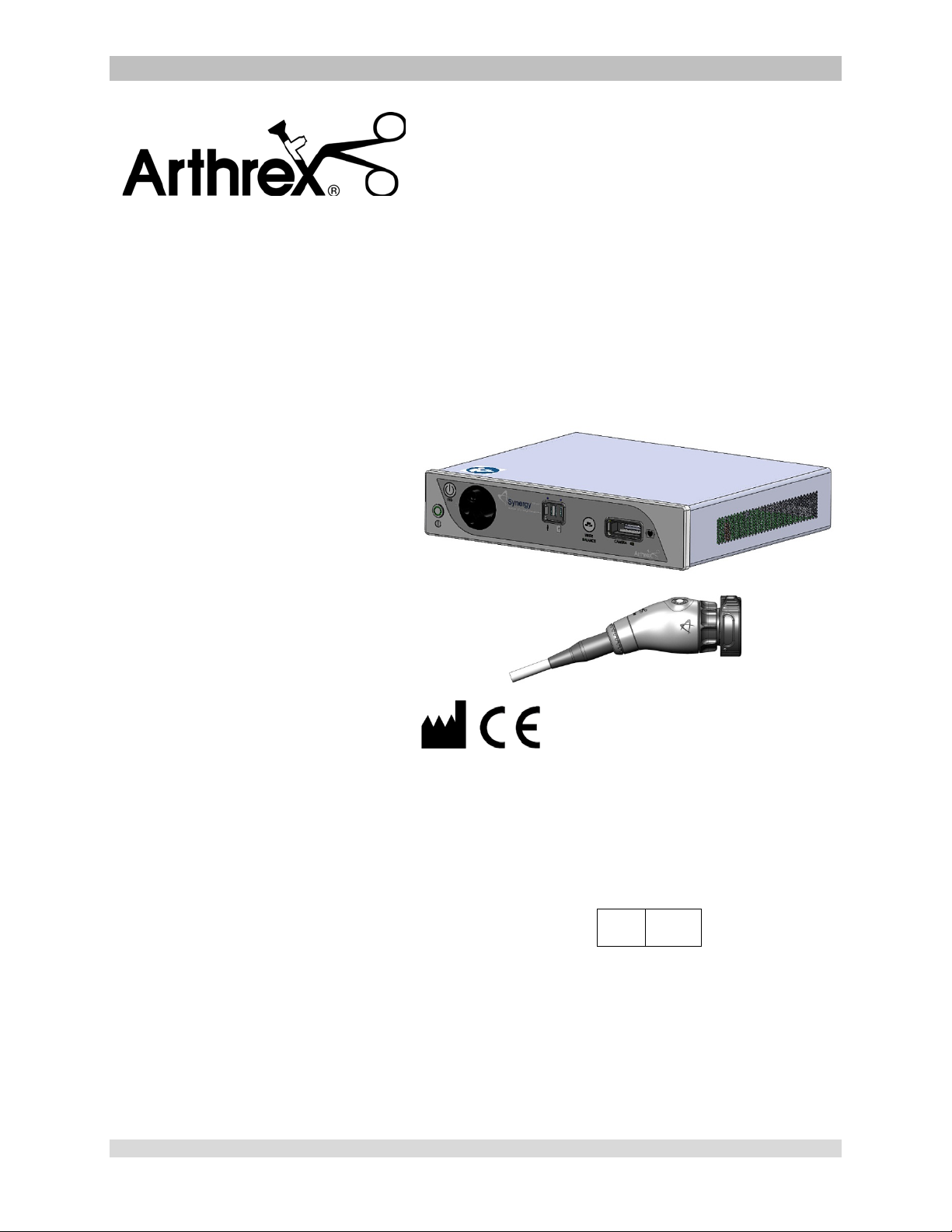
The Arthrex Synergy
Camera Head User’s Guide provides important information
for the safe operation of all components of the Synergy
Camera System, including accessories. Read this User’s
Guide thoroughly prior to using this system and keep it in
an easily accessible place for use by all operating
personnel. Read and follow all safety warnings, cautions
and precautions.
UHD4
System Camera Control Unit and
UHD4
AR-3210-0018
AR-3210-0021
AR-3210-0022
AR-3210-0023
AR-3210-0025
AR-3210-0026
AR-3210-0028
AR-3210-0029
AR-3210-0030
AR-3210-0031
Arthrex, Inc.
1370 Creekside Blvd.
Naples, FL 34108, USA
+1 (800) 934-4404
Technical Support
EC REP
Arthrex GmbH
Erwin-Hielscher-Strasse 9
81249 München, Germany
+49 89 909005-0
AR-3210-0032
950-0047-04A Page 1 of 69

This is not a warranty document. For all warranty information, including disclaimers, exclusi o ns,
terms, conditions, and related provis ions, refer to the “Arthrex U.S. Product Warranty” section of
the Arthrex, Inc. website, found at www.arthrex.com whose provisions are incorporated herein by
reference.
950-0047-04A Page 2 of 69

Table of Contents
1.0 Introduction ...................................................................................................................................... 4
1.1 Intended Use ................................................................................................................................. 4
1.2 Contraindications .......................................................................................................................... 4
1.3 Warnings and Precautions ............................................................................................................ 4
1.4 Symbol Definitions ........................................................................................................................ 9
1.5 End of Life, Environmental Directives ......................................................................................... 11
1.6 Initial Use of the Device .............................................................................................................. 11
1.7 Unpacking and Inspecting the Device ......................................................................................... 12
1.8 Returning the Device .................................................................................................................. 12
1.9 System Indicators ........................................................................................................................ 13
2.0 System Installation and Operation with Data Input Device ............................................................ 20
2.1 Installation .................................................................................................................................. 20
2.2 Accessories for Intended Use ...................................................................................................... 22
2.3 System Setup Facility and Surgeon Settings ............................................................................... 24
2.4 Icon Guide ................................................................................................................................... 33
2.5 Scheduling and Starting Cases .................................................................................................... 35
2.6 Status Notification Icons ............................................................................................................. 42
2.7 System Operation without Tablet Data Input Device ................................................................. 45
3.0 Maintenance ................................................................................................................................... 47
3.1 Life Expectancy............................................................................................................................ 47
3.2 Periodic Maintenance ................................................................................................................. 47
3.3 Cleaning and Sterilizing ............................................................................................................... 48
3.4 Troubleshooting .......................................................................................................................... 52
3.5 Resolving Error Messages ........................................................................................................... 55
3.6 Recommended Annual Camera Control Unit Maintenance Requirements ............................... 55
4.0 Technical Information ..................................................................................................................... 56
5.0 APPENDIX [Radio Module Information] ......................................................................................... 61
6.0 APPENDIX [Detailed EMC Information] ......................................................................................... 62
7.0 APPENDIX [SW Version access] ................................................................................................... 67
950-0047-04A Page 3 of 69

1.0 Introduction
WARNING: The safety and/or health
PRECAUTION: This contains
It is recommended that personnel study this
manual before attempting to operate, clean,
and/or sterilize the Arthrex Synergy
Synergy
safe and effective use of this equipment
requires the understanding of and
compliance with all warnings, precautionary
notices, and instructions marked on the
product, and included in this manual.
The Arthrex Synergy
comprised of:
NOTE: AR-3200-0020/AR-3200-0022
Synergy
UHD4
• AR-3200-0020 [Synergy
with Matrix]
• AR-3200-0021 [Synergy
Console]
• AR-3200-0022 [SynergyUHD4
Console with Matrix, HCRI]
• AR-3200-0023 [SynergyUHD4
Console, HCRI]
• AR-3210-0018 [HD, SynergyUHD4
Camera Head, autoclavable]
• AR-3210-0021 [HD SynergyUHD4
C-Mount Camera Head,
autoclavable]
• AR-3210-0022 [HD SynergyUHD4
C-Mount Camera Head, 0 Degree,
autoclavable]
• AR-3210-0023 [4K SynergyUHD4
Camera Head, autoclavable]
• AR-3210-0025 [4K SynergyUHD4 C-
Mount Camera Head, autoclavable]
• AR-3210-0026 [4K SynergyUHD4 C-
Mount Camera Head, 0 Degree,
autoclavable]
• AR-3210-0028 [4K SynergyUHD4 C-
Mount w/20 foot cable, autoclavable]
• AR-3210-0029 [4K SynergyUHD4
Broadband Camera Head,
autoclavable]
• AR-3210-0030 [4K SynergyUHD4 C-
Mount Broadband Camera Head,
autoclavable]
• AR-3210-0031 [4K SynergyUHD4
Ultra Camera Head, autoclavable]
• AR-3210-0032 [4K S ynerg yUHD 4
Ultra C-Mount Camera Head,
autoclavable]
UHD4
Consoles or Camera Control Units
System and accessories. The
UHD4
System is
UHD4
Console
UHD4
(CCU) are identical to AR-3200-0021/AR-32000023 CCUs except that AR-3200-0020/AR3200-0022
incorporate the Matrix PWA for
transmission of UHD4 data by fiber optic.
1.1 Intended Use
This system is designed for use by
physicians and surgeons and is intended for
endoscopic camera use in a variety of
endoscopic surgical procedures, including
but not limited to, orthopedic, laparoscopic,
urologic, sinuscopic and plastic surgical
procedures. It is also intended to be used as
an accessory for microscopic surgery.
1.2 Contraindications
Do not use the device if endoscopic surgery
is contraindicated.
Do not use the device if the environmental
conditions for use do not meet the standards
or regulations defined in the accompanying
documents.
1.3 Warnings and Precautions
The words WARNING, PRECAUTION, and
NOTE carry special meanings and they should
be read carefully.
of the patient, user, or a third party is
at risk. Comply with this warning to
avoid injury to the patient, user, or
third party.
information concerning the intended
use of the device or accessory.
Damage to the equipment is
possible if these instructions are not
followed.
NOTE: A note is added to provide additional,
focused, information.
1.3.1 WARNINGS
• This equipment is designed for use
by medical professionals com plet el y
familiar with the required techniques
and instructions for use of the
equipment. Prior to using the device,
950-0047-04A Page 4 of 69
read and follow all warning and
precautionary notices and
instructions marked on the product
and included in this manual. Become
familiar with the operation and
function of this device and
associated accessories. Failure to
follow these instructions can lead to:
• Life-threatening injuries to the pati ent
• Severe injuries to the surgical team,
nursing or service personnel, or
• Damage or malfunction of the device
or accessories.
1. Do not open or attempt to service this
system, as this may void your
warranty. There are no userserviceable parts inside. Removing the
cover may introduce an electric shock
hazard by exposing you to dangerous
high voltages or other risks. If the system
malfunctions, return it for service
immediately.
2. For the protection of the patient it is
recommended that a back-up camera system
for the Arthrex Synergy
maintained, sterilized, and ready to be
implemented.
3. For the protection of the patient it is essential
that the endoscopic video system
interconnection is complete and produces a
viable color picture on the surgical monitor
PRIOR to administration of patient
anesthesia.
4. Disconnect camera head and endoscope
from the patient prior to applying cardiac
defibrillation to patient.
5. Only the physician can evaluate the clinical
factors involved with each patient and
determine if the use of this device is
indicated. The physician must determine the
specific technique and procedure that will
accomplish the desired clinical effect.
6. This device and its accessories are to be
used only by physicians and medical
assistants under the direction of a physician
with appropriate technical q ual if icatio ns .
7. This device shall only be used with original
and manufacturer’s accessories
and replacement parts. Use of
UHD4
video system be
other parts or materials may degrade safety.
8. Do not use in the presence of flammable
anesthetics, gases, disinfecting agents,
cleaning solutions, or any material
susceptible to ignition due to electrical
sparking.
9. Equipment grounding is vital for safe
operation. Plug the power cord into a properly
earthed mains supply outlet whose voltage
and frequency characteristics are compatible
with those listed on the unit or in this manual.
Do not use plug adapters or extension cords;
such devices defeat the safety ground and
could cause injury.
10. This equipment should not share an electrical
outlet or grounding with life supporting or life
sustaining equipment.
11. If one or more mains powered units are
connected simultaneously to one socket by
the means of a distribution box, the sum of
the individual leakage currents may exceed
the tolerated limits.
12. Before each use, the outer surface of the
portions of the Endoscope and any
Endoscopically Used Accessory, which are
intended to be inserted into the patient, should
be checked to ensure there are no unintended
rough edges, sharp edges or protrusi ons whic h
may cause a safety hazard.
13. Refer to Insufflation Device Instructions
regarding safety hazards to patients resulting
from gas emboli.
14. The leakage current through the patient could
increase when using endoscopes with
powered accessories.
15. When Endoscopes are used with Energized
Endoscopically Used Accessories, the
Patient Leakage Currents may be additive.
This is particularly true if a CF Applied Part is
used, in which case a Type CF
Endoscopically Used Accessory should be
used to minimize total Patient Leakage
Current.
16. Applied Parts of other ME Equipment used
within the configuration for Endoscopic
Application shall be type BF or CF Applied
Parts.
17. Explosive gas concentrations inside the
patient can cause hazards while using HighFrequency Endoscopically Used Accessories.
950-0047-04A Page 5 of 69

18. For the protection of service personnel, and
for safety during transportation, all devices
and accessories that are returned for repair
must be prepared for shipment as described
in “Returning the Device” of this manual.
The manufacturer has the right to refuse to
carry out repairs if the product is
contaminated.
19. This equipment/system may cause radio
interference or may disrupt the operation of
nearby equipment. It may be necessary to
take mitigation measures, such as re-
UHD4
orienting or relocating the Synergy
Video System or shielding the location.
20. NOT for use in an Oxygen Rich Environment.
21. NO Modifications of this equipment are
allowed.
22. Connecting any equipment that has not been
supplied as part of this ME System to Multiple
Socket Outlets may result in increased
leakage currents. Use an IEC Approved
Isolation Transformer to isolate any such
interconnections from the ME System.
illumination in small cavities, or if the
endoscope’s distal end is placed in
close proximity with the tissue. This can
cause the temperature of the body
tissue to rise in excess of 106 °F (41°C).
Burns or thermal damage to surgical
equipment may also result.
• Avoid prolonged exposure to intense
illumination.
• Use the minimum level of illumination
necessary to satisfactorily illuminate the
target area.
• Do not place the endoscope’s distal end
or light guide connector on the patient’s
skin, on flammable materials or on heat
sensitive materials.
• Turn the light source off when detaching
the endoscope from the light guide
cable.
• Allow the endoscope and light guide
cable to cool down after use before
reprocessing.
23. Before each use or after changing viewing
modes/settings the Operator should check to
ensure that the view observed through the
Endoscope provides a live image (rather than
a stored one) and has the correct image
orientation.
24. Risk of burns!
LED Light Engines emit large amounts of
light and thermal energy. As a result:
• Always keep the LED Li ght Eng ine in
the STANDBY mode when not in use.
The endoscope light guide connection
can get extremely hot as result of high
intensity light, giving rise to high
temperatures in front of the light
emission window which may cause
severe burns.
• Surface temperatures of the insertion
portion of the endoscope as well as light
guide connectors on the Camera
Control Unit (CCU) and the endoscope
rise during use.
• Potential thermal injury to the patient’s
tissue and skin may result from
prolonged exposure to the intense
25. High Frequency [HF] electrical surgical
instruments may lead to severe patient
injuries and/or damage to the endoscope.
Care should be taken to ensure that the
working element is kept within field of view to
prevent accidental burns. A sufficient
distance from the tip of the endoscope to
other conductive accessories and
instruments should be maintained (10 mm)
before activating the HF output to prevent
burns and damage to the endoscope. Refer
to the HF Surgical Device Instructions for
proper and safe use.
26. HF surgical instrum ents m ay interfer e with
video images. To prevent such interference,
HF equipment and video imaging equipment
should be connected to different power
supply circuits.
27. Use of Lasers in surgery may result in Eye
Damage or damage to the endoscope from
reflected laser energy. Refer to the Laser
Device Instructions for proper and safe use.
• When using a laser always wear
protective glasses designed for the
laser’s wavelength.
950-0047-04A Page 6 of 69
• Cover the patient’s eyes, or use
protective glasses designed for the
laser’s wavelength.
• To prevent damage to the
Endoscope, the Laser should be
activated only after the tip of the laser
can be seen through the endoscope.
28. To ensure FCC RF Exposure limits for base
station transmissions devices are met, a
distance of 20 cm or more shall be
maintained between the Camera Control Unit
(which contains the antennas), and persons
during operation. To ensure compliance, an
operator closer than 20 cm to Camera
Control Unit is not recommended.
1.3.2 PRECAUTIONS
1. United States Federal law restricts sale of
this device to or on the order of a physician.
2. Only use the device with Arthr ex compatible
equipment listed in Section 2.2.
3. Inserting an incompatible Camera Head into
the camera receptacle (see Figure 1) can
result in damage to the CCU.
4. The warranty becomes void and the
manufacturer is not liable for direct or
resulting damage if:
• The device or the accessories are
improperly used, prepared or
maintained;
• The instructions in the manual are not
adhered to;
• Non-authorized persons perform
repairs, adjustments or alterations to the
device
• Non-authorized persons open the
device.
NOTE: Receipt of technical documentation
from the manufacturer does not authorize
individuals to perform repairs, adjustments,
or alterations to the device or accessories.
Only authorized service personnel may
perform repairs, adjustments or alterations
on the device and accessories. Any violation
will void the manufacturer’s warranty.
Authorized service technicians are trained
and certified only by the manufacturer. The
Manufacturer will make available on request
circuit diagrams, component part lists,
descriptions, calibration instructions and
other information required for service to any
Arthrex Authorized Service Center.
5. This device should only be used in
compliance with its intended use.
6. Prior to each use, the CCU and all
associated equipment must be inspected for
proper operation. Visually inspect lenses to
ensure there are no scratches, chips or
cracks.
7. To carry out safe operation, it is absolutely
necessary to carry out proper care and
maintenance of the device and acces s ories .
See “Maintenance” section of this manual.
8. Ensure that the available mains voltage
matches the mains voltag e data on the rear
of the device which is located near the
appliance inlet module.
9. This device may only be connected to
endoscopes which, in their intende d use and
technical specifications, are appropriate for
use with the device for the intended medical
procedure. The endoscopes must comply
with the latest version of DIN EN 60601-2-18
and ISO 8600.
10. Do not expose the Camera Control Unit
(CCU) to moisture, or operate it in a wet
area, or store liquids above the CCU.
11. Do not excessively bend or kink instrument
power cord or camera head cable.
12. Handle all equipment carefully. If the CCU or
camera head is dropped or damaged in any
way, return it immediately for service.
13. If the camera head or camera head cable
are damaged in any way, or cable or
connector jacket are cut, do not autoclave
camera head, or immerse camera head in
liquid (water, chemical disinfectants or
sterilants, etc.). Notify your Arthrex Sales
Representative. If it is necessary to return
the camera head to Arthrex for service,
disinfect the camera head before shipping
and reference “Returning the Device”.
14. Store camera head and all accessories in a
protective container to prevent damage
during storage. Do not store CCU where it
950-0047-04A Page 7 of 69

will be exposed to temperatures in excess of
140°F (+ 60°C).
15. Additional equipment connected to medical
electrical equipment must comply with the
respective IEC or ISO standards (e.g. 60950
for data processing equipment).
Furthermore all configurations shall comply
with the requirements for medical electrical
systems (see IEC 60601-1 ). Anybody
connecting additional equipment to medical
electrical equipment configures a medical
system and is therefore responsible that the
system complies with the requirements for
medical electrical systems. Attention is
drawn to the fact that local laws take priority
over the above mentioned requirements. If
in doubt, consult your local representative,
or the technical department.
16. Any person who connects external
equipment to signal i nput and signal output
ports or other connectors has formed a
system and is therefore responsible for the
system to comply with the requirements of
IEC 60601-1. If in dou bt, contact a qual ified
Biomedical technician or your local
representative.
17. This equipment has been tested and found
to comply with the Class A limits for medical
devices to IEC 60601-1-2:. These limits are
designed to provide reasonable protection
against harmful interference in a typical
medical installation. This equipment
generates and can radiate radio frequency
energy and, if not installed and used in
accordance with the instructions , may cause
harmful interference to other device(s) in the
vicinity. However, there is no guarantee that
interference will not occur in a particular
installation. If this equipment does cause
harmful interference to other devices, which
can be determined by turning the equipment
off and on, the user is encouraged to try to
correct the interference by one or more of
the following measures:
(a) Reorient or relocate the receiving
device.
(b) Increase the separation between the
equipment.
(c) Connect the equipment into an outlet on
a circuit different from that to which the
other devices are connected.
(d) Consult the manufacturer or field service
technician for help.
This unit was not evaluated for use with
electrosurgical devices which access the
site via the same endoscope as the light
engine and camera. The unit must be reevaluated prior to use with electrosurgical
devices when they will operate through the
same endoscope as the light source and
camera.
18. After each use, thoroughly clean unit and
accessories (See “Cleaning and
Sterilizing”).
NOTES:
1. Observe all national waste management
regulations.
2. Do not dispose of WEEE as unsorted
municipal waste.
950-0047-04A Page 8 of 69
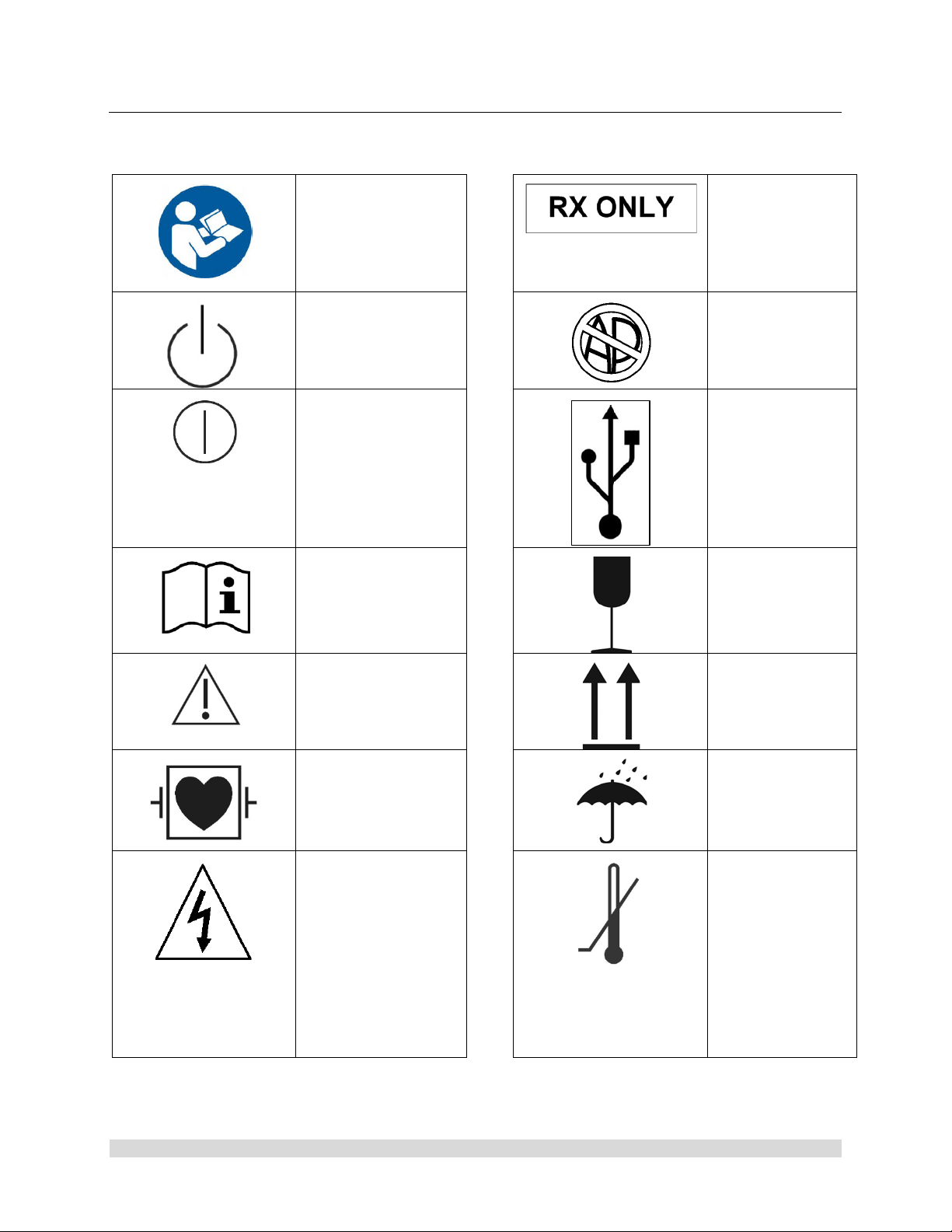
1.4 Symbol Definitions
Physician.
components.
Safety Sign
Follow Operating
Instructions
Power Standby/On
ON-OFF
Push-Push
Attention, Consult
Accompanying
Documents
Caution: Federal
Law Restricts
this device to
sale by or on the
order of a
Not for use in the
Presence of
Flammable
Anesthetics.
USB Tablet
Computer
Connection
Fragile
Precaution of
Warning Notice
Defibrillation Proof
Type CF Equipment
Electrical Hazard,
Dangerous Voltages
are Present. Never
attempt to repair the
equipment. Only
Trained Service
Personnel may
remove the cover, or
obtain access to
system
This Side Up
Keep Dry
Temperature
Limits for
Storage and
Transport
950-0047-04A Page 9 of 69
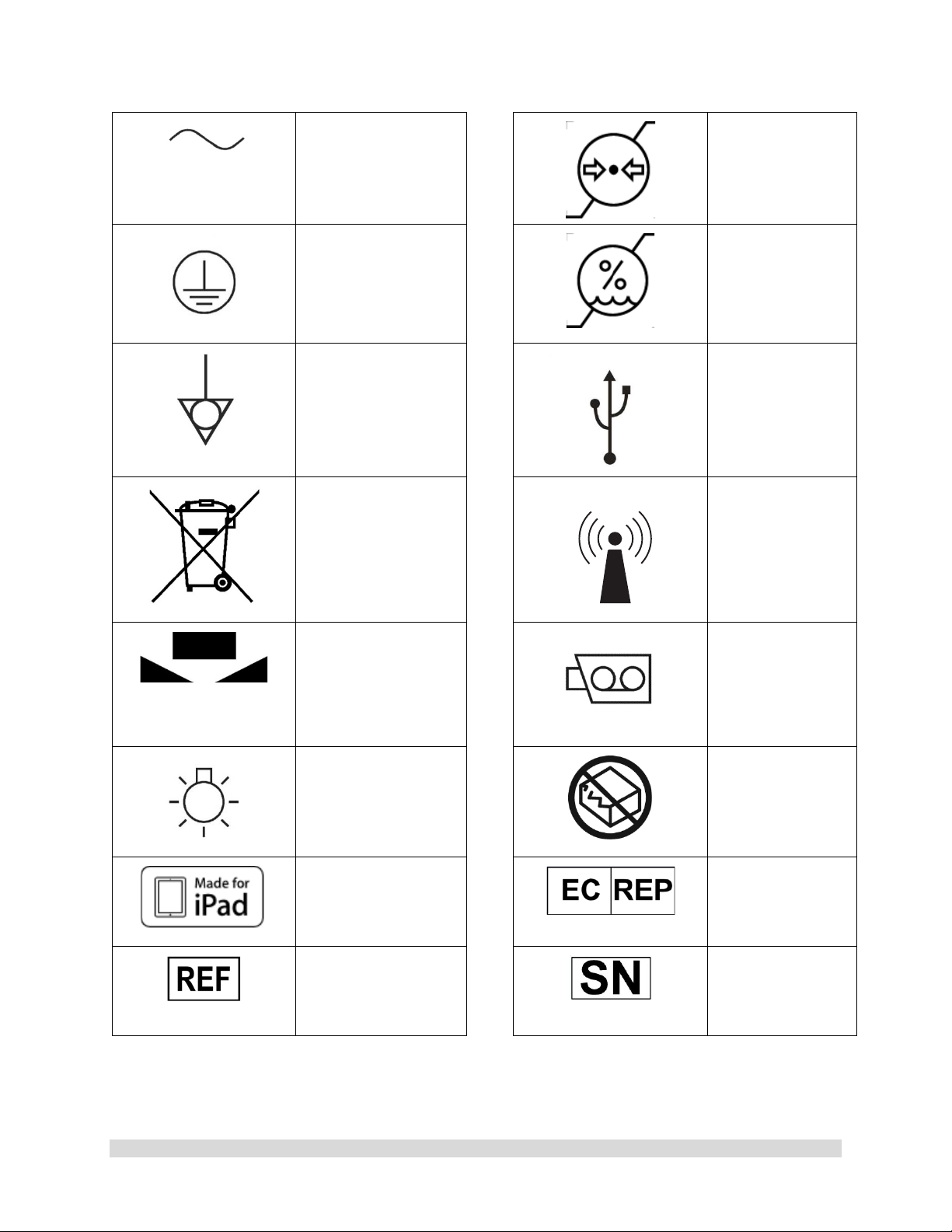
Alternating Current
Equipment] Symbol.
Pressure Limits
for Storage and
Transport
Protective Earth
[Ground]
Equipotential
[Equipment
Potential]
WEEE [Waste
Electronics and
Electrical
Regarding European
Union End-of-Life of
Product.
White Balance
Symbol
Humidity Limits
for Storage and
Transport
Universal Serial
Bus
RF Symbol. Non-
ionizing
Electromagnetic
Radiation
Color Video
Camera
950-0047-04A Page 10 of 69
LED Light
MFi
Made for iPad
Catalog Number
Do Not Use if
Damaged
EC Rep
Serial Number

1.5 End of Life, Environmental Directives
WEEE Directive [2012/19/EU] on Waste
Electrical and Electronic Equipment
The Directive on Waste Electrical and Electronic
Equipment obliges manufacturers, importers,
and/or distributors of electronic equipment to
provide for recycling of the electronic equipment
at the end of its useful life.
Do not dispose of WEEE in unsorted municipal
waste.
The WEEE symbol on the product or its
packaging indicates that this product must not
be disposed of with other waste. Instead, it is
your responsibility to dispose of your waste
equipment by handing it over to a designated
collection point for the recycling of Waste
Electrical and Electronic Equipment. The
separate collection and recycling of your waste
equipment at the time of disposal will help
conserve natural resources and ensure that it is
recycled in a manner that protects human health
and the environment. For more information
about where you can drop off your medical
endoscopic video equipment at the end of its
useful life for recycling, please contact Arthrex
Customer Service Department.
The Camera Control Unit (CCU)
contains a Lithium Coin BATTERY. The
BATTERY must be recycled or disposed
of properly.
NOTE for State of California, USA:
State of California Requirement: Lithium
Batteries contain Perchlorate Material -special
handling may apply. See
www.dtsc.ca.gov/HazardousWaste/Perchlorate
In the US a list of recyclers in your area can be
found at www.eiae.org/
1.6 Initial Use of the Device
WARNINGS:
1. The device is only completely isolated
from the mains if the power plug is
disconnected from the device’s power
inlet module. Avoid positioning
equipment such that removal of plug is
difficult.
2. The electrical installation of the operating
room where the device is used must
comply with applicable national
requirements.
3. Loss of the Mains Voltage may result in
an unacceptable risk due to loss of
Clinical Function. An Uninterruptable
Power Supply [UPS] is recommended to
mitigate this risk.
4. The device is not intended for use in
areas of explosion hazards. If explosive
nitrous gases are used the Camera
Control Unit may not be operated in the
danger zone.
5. Do not simultaneously touch the Camera
Control Unit and the patient. Camera
Control Unit is intended to be used
outside the Patient Vicinity.
6. Additional peripheral equipment
connected as part of the Endoscopic
Video System must meet the
requirements of the following
specifications:
• IEC 60950 for Information
Technology Equipment.
• IEC 60601-2-18 for endoscopic
devices.
• IEC 60601-1 for medical electrical
equipment.
7. All final Endoscopic Video Systems m ust
meet the requirements of IEC 60601-1.
8. Whoever connects additional equipment
to signal input or signal output is
obligated to meet the requirements of the
IEC 60601-1 standard.
950-0047-04A Page 11 of 69

CAUTION: Do not install the device
in a location near heat sources such
as air ducts or radiators and do not
expose the device to direct sunlight,
excessive dust, or mechanical vibration.
1.7 Unpacking and Inspecting the Device
Upon receipt, carefully unpack the Synergy
Camera Control Unit (CCU) and accessories.
Ensure contents are complete and are free from
damage. If any damage is noted contact your
Arthrex Customer Service. Contact the
Manufacturer for Return Authorization PRIOR to
shipping your device for service. Save ALL
packaging materials; they may be needed to
verify any claims of damage by the shipper.
UHD4
1.8 Returning the Device
If it becomes necessary to return the device,
always use the original pack aging. T he
manufacturer does not take responsibility for
damage that has occurred during transportation
if the damage was caused by inadequate
transport packaging. Please make sure that all
required information has been supplied. Call
Arthrex for an RMA Number for the device return
for service.
• Owner’s Name
• Owner’s Address
• Owner’s Daytime Telephone Number
• Device type and model.
• Serial Number
• Detailed explanation of the damage.
NOTE:
1. The CCU shall be cleaned per
section Cleaning and
Sterilization prior to returning for
service.
2. The Camera Head shall be
cleaned and Sterilized per
Cleaning and Sterilization p rior
to returning for service. Camera
Head shall be clearly labeled as
“Sterile.”
Equipment will not be repaired unless
decontaminated as stated abo ve prior to return
to the manufacturer.
950-0047-04A Page 12 of 69
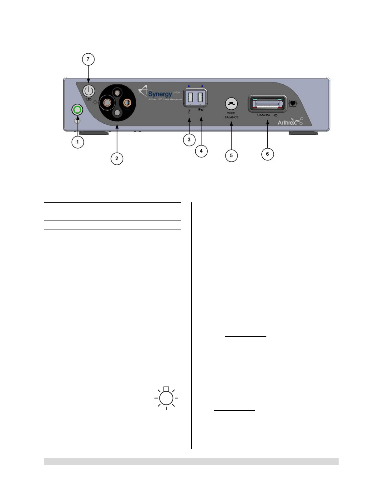
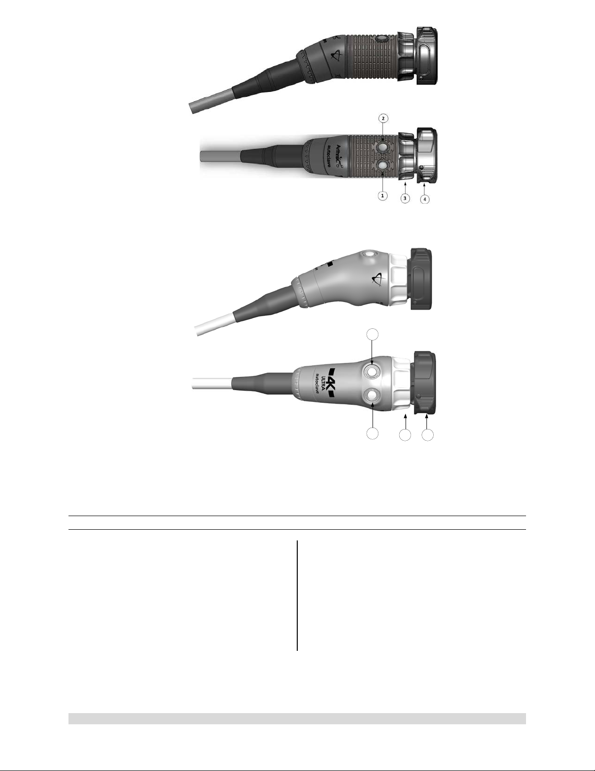
Figure 1- Synergy
UHD4
1.9 System Indicators
UHD4
1.9.1 Synergy
1. On/Standby Switch-The On/Standby switch
toggles the Camera Control Unit (CCU)
between ON [operational mode] and
STANDBY. The Green LED will illuminate
when the CCU is in the ON mode. Press and
HOLD the switch to toggle between ON and
STANDBY.
2. Light Guide Turret-Turret for Light Guide
input
Front Panel
• Wolf Input
• Storz Input
• ACMI Input
• Olympus Input
NOTE: Rotate Light Guide Turret until the
appropriate port is aligned with LED
INDICATOR then Insert
Light Guide.
Front Panel [AR-3200-002x]
3. USB Port-Connect USB devices here.
4. iPAD USB Port-Connect iPAD to this port.
5. “WHITE BALANCE” Button-Press to initiate
camera white balance.
6. “CAMERA” Input Connection-Insert the
camera head connector here. The camera
head connector and rec eptacle are sp ecially
keyed to prevent the camera head from being
improperly connect ed. Ensure that the “U P”
label on the camera head connector is facing
upwards when the camera head connector is
inserted.
PRECAUTION: Ensure camera head
contacts are clean and dry a nd cooled
15 minutes prior to insertion.
7. LED Light Engine On/Standby Switch-The
Light S ource On/Standb y Switch to ggles the
Light Source between ON [Operational
Mode] and STANDB Y.
PRECAUTION:
Use only FUSED Light Guides to ensure
proper operation of LED Light Engine.
950-0047-04A Page 13 of 69
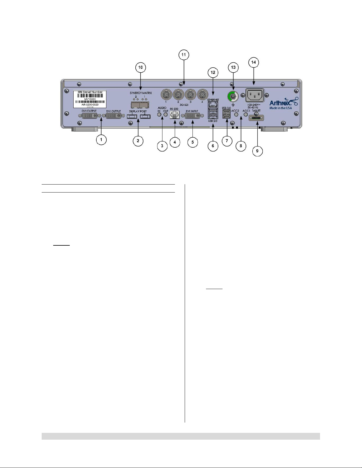
Figure 2- Synergy
1.9.2 Rear Panel
1. “DVI” Video Output Connectors-Supplies a
digital video signal output in DVI-D format.
2. Display Ports (2X)-Supplies UHD Video
Signal output in either 1.1 [dual cable] or 1. 2
[MST].
NOTE: Arthrex recommends connecting
Synergy
UHD4
to the primary surgical monitor via
multiple output types (e.g., display port and
DVI, Synergy Matrix a nd 3G-SDI) in the event
that one type of connection is lost.
3. Audio In / Audio Out-Audio In: Line Level
Audio input for Microphone. Audio Out: Line
Level Audio output to Medical Grade Devices.
4. RS-232 Connector-Isolated connection to
devices requiring Serial Contr ol.
5. DVI Input-1080P/60 Input for Picture in Picture
[PIP].
6. USB 2.0 (2X)-USB 2.0 Connection.
7. USB 3.0 (2X)-USB 3.0 Connection.
8. Accessory Ports (Inputs/Outputs (2X) mini
Stereo-Phone Connectors)-Accessory ports
allow for control of the CC U with a footswitch
or external device or for the CCU to control
external devices via the camera head buttons.
9. Tablet Connection-Connection for Tablet
Data Input device. Provides for data
interchange and tablet charging.
UHD4
Rear Panel
10. Synergy Ma tr ix [Synergy Matrix Only]-Fiber
Optic output to Matrix Monitor (point to point or
managed) via Custom SFP+ Fiber
Transceivers. Use Output 1 and 2 for 4K Video.
Custom SFP+ Fiber Transceivers and Matrix
License may be obtained from Arthrex
Customer Service.
11. 3G-SDI Out-1080P/60 Output.
12. Ethernet Connector-Isolated 10/100 Mb/sec.
13. Potential Equalization Connector (POAG)-
Potential Equalization Connector per DIN
42801.
NOTE: The purpose of the Potential
Equalization Connector is to equalize the
potentials between diff erent met al parts of the
various Medical Electrical [ME] equipment
which make up a Medical Electrical system, or
to reduce differences of potential which can
occur during oper ation between th e bodies of
the Medical Electrical devices and conduct ive
parts of other objects. The Potential
Equalization Connector may be connected
directly between any ME Devices, or to a
common busbar of the electrical installation.
Reference IEC 60601-1 for ME Systems.
14. IEC 320 Power Inlet Module (100-240V~,
50/60 Hz)-The CCU is equipped with a
switching power supply that automatically
adjusts to the line voltage being used. Accepts
the supplied hospital grade power cord.
950-0047-04A Page 14 of 69
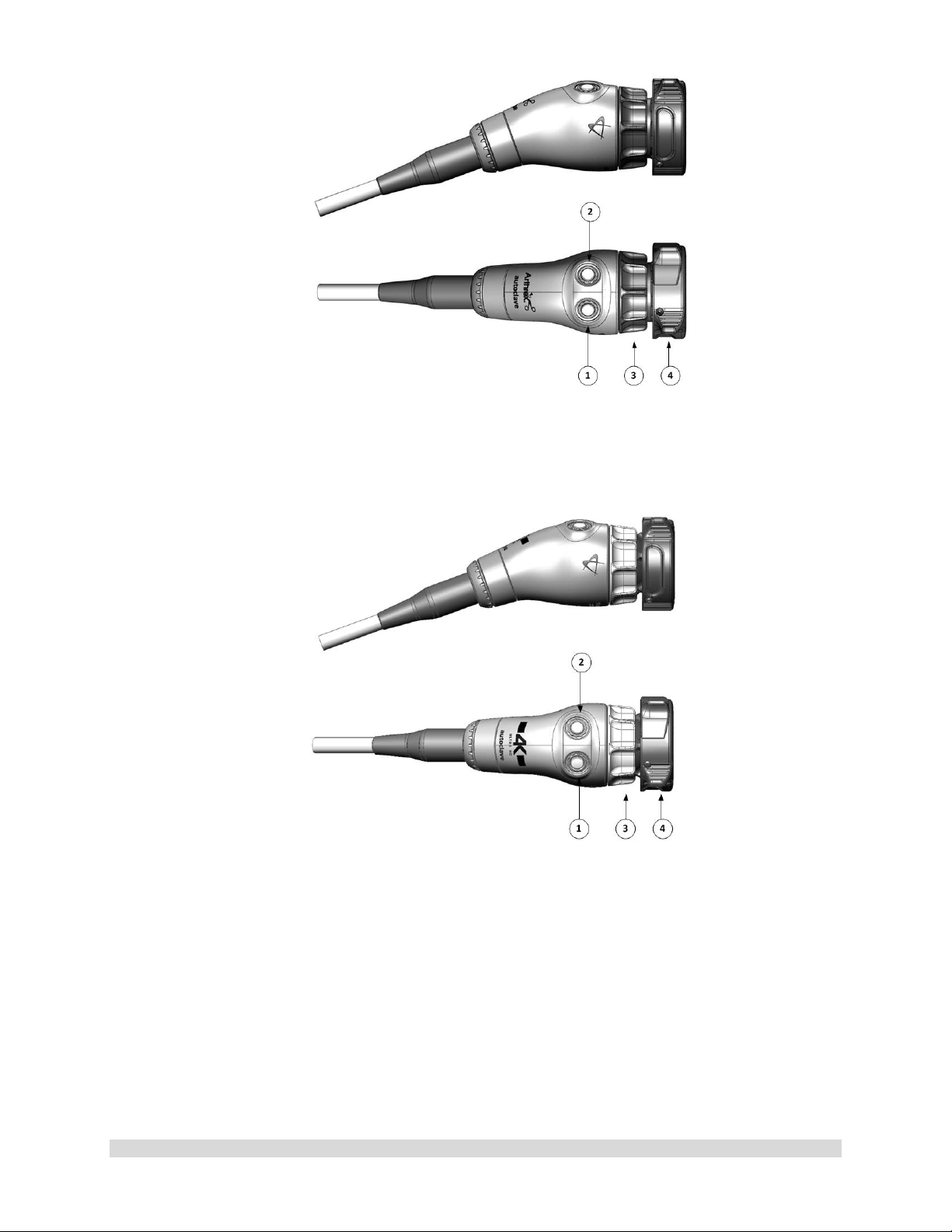
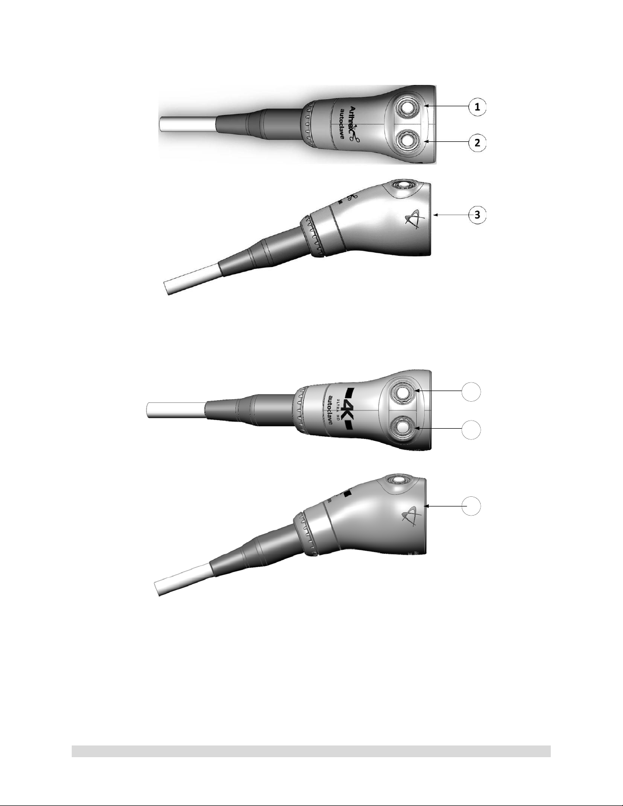
Figure 3- AR-3210-0023 4K SynergyUHD4 Camera Head, autoclavable
Figure 4- AR-3210-0029 4K SynergyUHD4 Broadband Camera Head, autoclavable
950-0047-04A Page 15 of 69
1
2
3
4
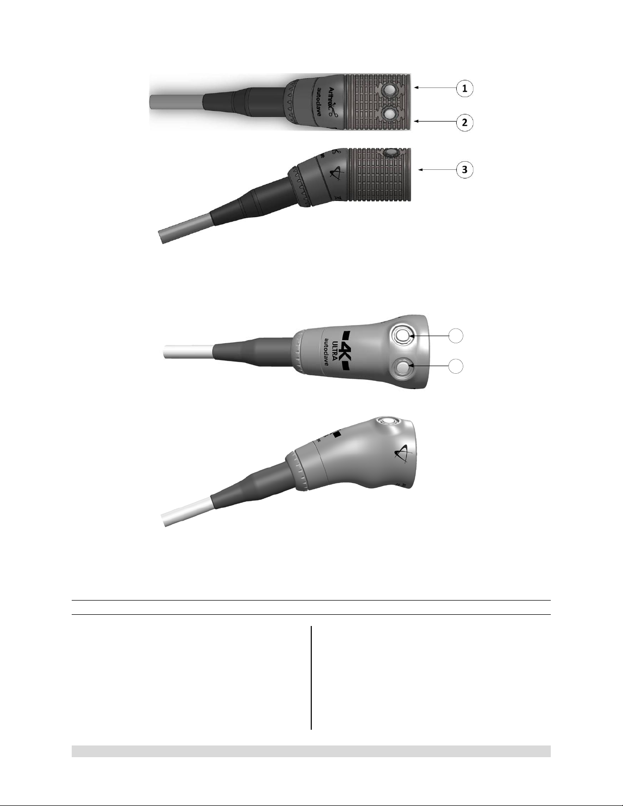
Figure 5-AR-3210-0018 HD, SynergyUHD4 Camera Head, autoclavable
Figure 6-AR-3210-0031 4K Ultra SynergyUHD4 Camera Head, autoclavable
1.9.3 Camera Heads with Integrated Optics
1. Button 1-A programmable button that
can activate various functions of the
camera. See “Optional T abl et Dat a Inp ut
Device” for programming information.
2. Button 2-A programmable button that
can activate various functions of the
camera. See “Optional Tablet Data Input
3. Focus Ring-Used to sharpen, or bring
into focus, the image detail.
4. Grasping Mechanism-Accepts and
locks into place the compatible scope.
DIN 58105 compliant endoscope
interface.
Device” for programming information.
950-0047-04A Page 16 of 69
1
2
3
Figure 7-AR-3210-0025 4K SynergyUHD4 C-Mount Camera Head, autoclavable, AR-3210-0028 4K
SynergyUHD4 C-Mount w/20 foot cable, autoclavable and
Not Pictured AR-3210-0026 4K SynergyUHD4 C-Mount Camera Head, 0 Degree, autoclavable
Figure 8-AR-3210-0030 4K SynergyUHD4 C-Mount Broadband Camera Head, autoclavable
950-0047-04A Page 17 of 69
1
2
Figure 9- AR-3210-0021 HD SynergyUHD4 C-Mount Camera Head, autoclavable, and Not Pictured
AR-3210-0022 HD SynergyUHD 4 C-Mount Camera Head, 0 Degree, autoclavable
Figure 10- AR-3210-0032 [4K Ultra SynergyUHD4 C-Mount Camera Head, autoclavable]
1.9.4 C-Mount Camera Heads
1. Button 1-A programmable button that
can activate various functions of the
camera. See “Optional Tablet Data Input
Device” for programming information.
2. Button 2-A programmable button that
can activate various functions of the
camera. See “Optional Tablet Data Input
Device” for programming information.
3. C-Mount Threads-Accepts standard CMount Optical Couplers.
950-0047-04A Page 18 of 69
950-0047-04, Rev. A English
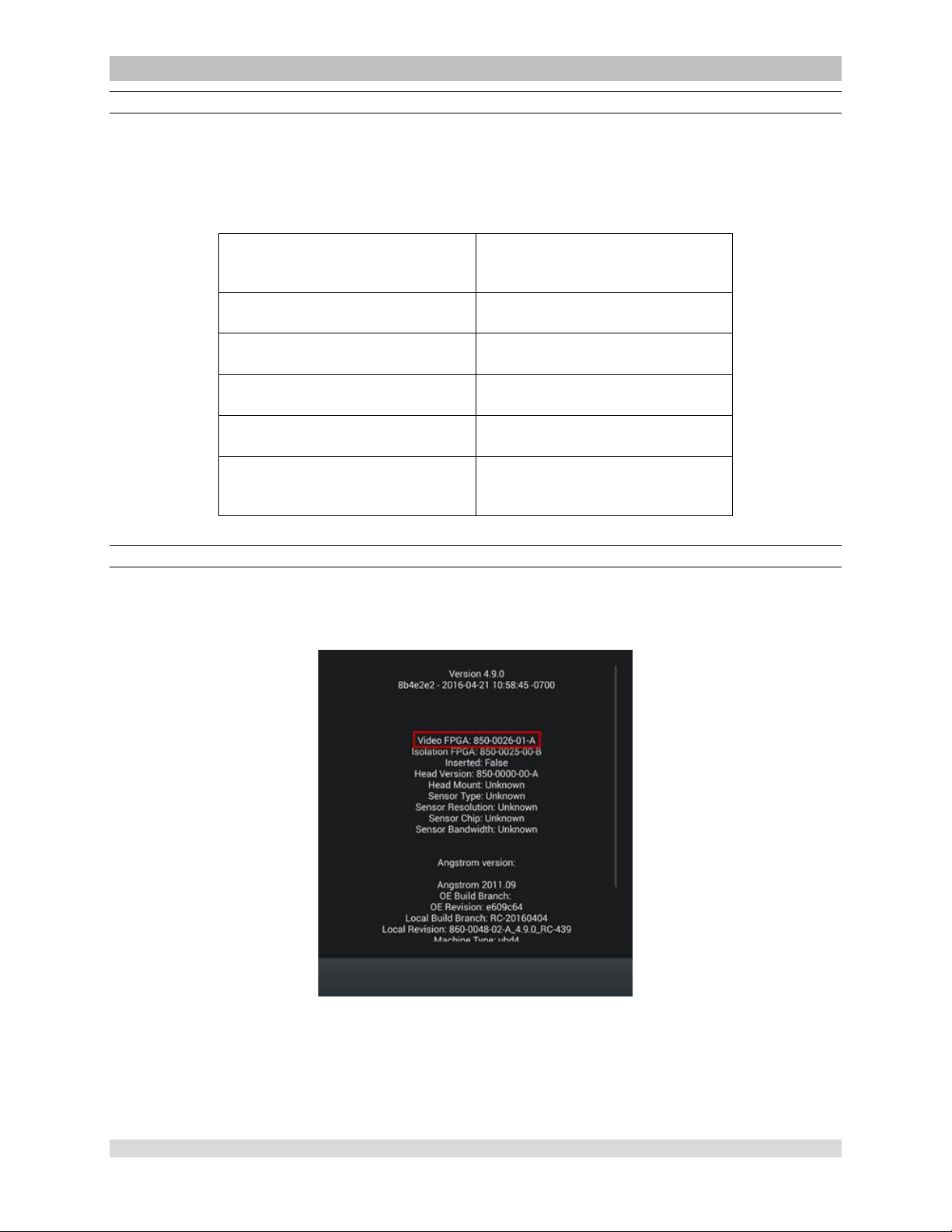
AR-3210-XXXX Camera Head SynergyUHD4 Firmware Compatibility
CAUTION:
• Som e AR -3210-XXXX camera heads are only compatible with specific SynergyUHD4
firmware versions as shown in the following table. Attempting to use these camera heads
with incompatible SynergyUHD4 firmwar e may fail to produce an acceptable quality vide o
output on the surgical display.
Camera Head Compatible SynergyUHD4
Firmware Version
AR-3210-0029 850-0026-01-A or higher
AR-3210-0030 850-0026-01-A or higher
AR-3210-0031 850-0026-02-B or higher
AR-3210-0032 850-0026-02-B or higher
All other camera head models
mentioned in this IFU
Determining the Firmware Version of the Sy nergyUHD4 System
Firmware can be verified on the About screen, which is accessed by double tapping on the open blue
area of the home login screen and tapping the About option. The firmware version is listed under Video
FPGA as seen in the image below.
All versions
Figure 11- SynergyUHD4 Firmware Version
950-0047-01A Page 19 of 69

2.0 System Installation
and Operation with
Data Input Device
2.1 Installation
1. Your Synergy
indicate which software configuration is
enabled at boot up on the Vid eo Mon itor ’s
Splash screen.
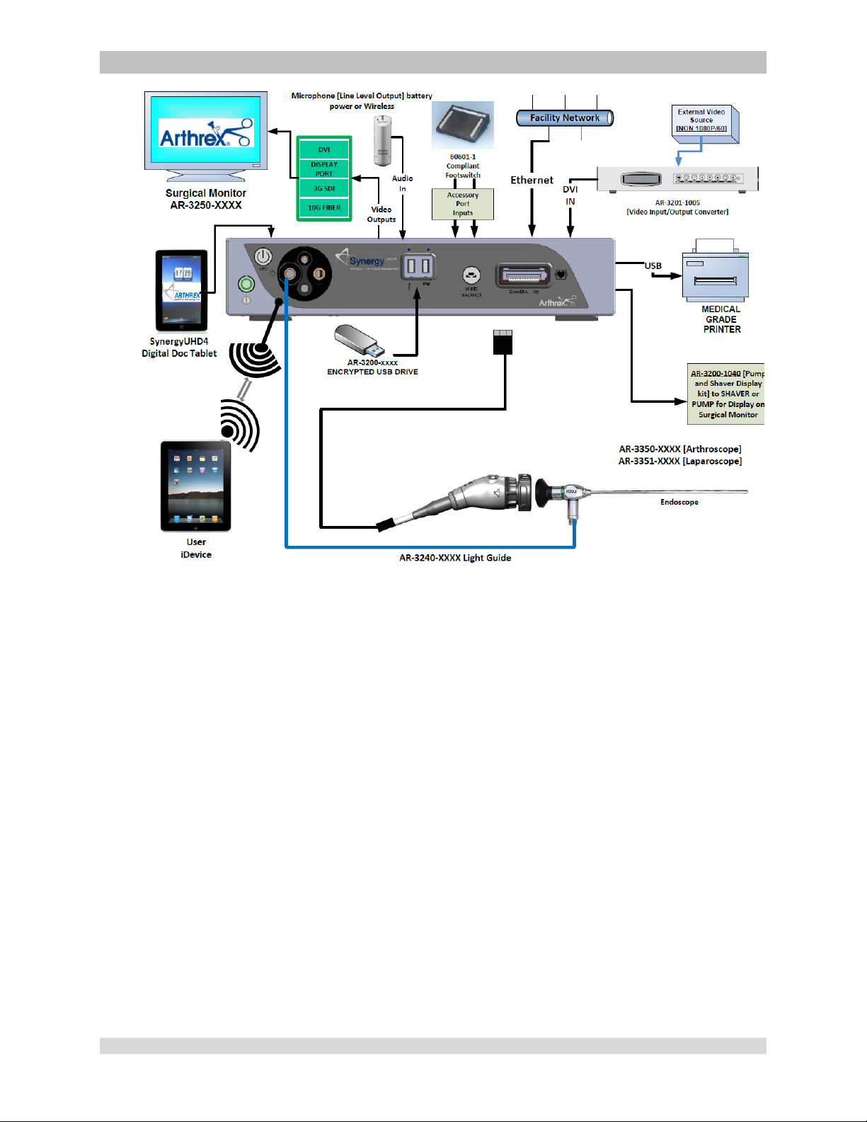
2.1.1 Typical System Installation
NOTE: See Typical Interconnect Diagram,
Figure.
NOTE: Synergy
tower or on an equipment boom.
1. Place Synergy
(CCU) on tower shelf or installed on
equipment boom.
2. Attach monitor to the tower or equipment
boom and connect monitor DC power cable
to the rear panel of the monitor as shown.
3. Attach Synergy
secondary tower arm or equipment boom.
Connect the cable from the Data Input
Device to the connector labeled “tablet” on
the back of the Synergy
4. Connect a Display Port cable to a Display
Port output on the rear panel of the
Synergy
of the Displa y Port cab le to the D ispl a y Port
input of the display monitor. (3G-SDI or D VI
cables may be used instead of Display Port
cables.) Note: Arthrex recommends
connecting Synergy
UHD4
Camera Control Unit will
UHD4
may be installed in a
UHD4
Camera Control Unit
UHD4
Data Input Device to
UHD4
CCU.
UHD4
CCU. Connect the other end
UHD4
to the primary
surgical monitor via multiple output types
(e.g., Display Port and DVI, Displa y Port and
3G-SDI) in the event that one type of
connection is lost.
5. If using a printer, connect the printer cable to
the USB connector on the rear panel of the
UHD4
Synergy
CCU. Connect the other end
of printer cable to the printer.
6. Plug the AC power cord into the
UHD4
Synergy
power inlet module and a
standard grounded AC Mains outlet (100240 V˜, 50-60Hz).
7. Insert the card edge connector of the
UHD4
Synergy
camera head into the camera
receptacle on the front of the CCU. Ensure
the camera had connector contacts are clean
and dry prior to insertion.
WARNING: Inserting an incompatible
Camera Head into the camera receptacle
(see Figure 1) can result in damage to the
CCU.
8. Connect the Light Guide cable into the Light
Guide receptacle on the front panel of the
UHD4
Synergy
CCU. Attach the other end of
the Light Guide cable to the endoscope.
9. Insert the endoscope into the Synergy
UHD4
camera head grasping mechanism or into
the C-Mount Coupler for C-Mount Heads.
10. Press the LED Light Engine On/Standby
Switch to activate the LED light engine.
NOTE: If there is no Light Guide cable
connected to the Synergy
UHD4
CCU,
pressing the On/Standby Switch will no t
activate the LED light engine until one is
connected.
950-0047-04A Page 20 of 69
950-0047-04, Rev. A English
Figure 12- Synergy
Documentation Tablet [Integrated Optics Heads]
UHD4
Typical Interconnect Diagram With OPTIONAL Digital
950-0047-01A Page 21 of 69

Arthrex Synergy
System Accessories
Part Number
Description
AR-3250-XXXX
Arthrex Monitors
DR80MD/NKIT
AR-3355-XXXX
Arthrex C-Mount Arthrosc o pes
AR-3200-1013
Figure 13- Synergy
UHD4
2.2 Accessories for Intended Use
SONY UP-PR80MD
SONY UP-PR80MD with UP-
AR-3350-XXXX
AR-3351-XXXX
AR-3352-XXXX
AR-3200-1007
Typical Interconnect Diagram [C-MT Heads]
UHD4
Medical Grade Printers
Arthrex Arthroscopes
Arthrex Laparoscopes
Arthrex Hi Mag Laparoscopes
SynergyUHD4 Synergy Documentation Tablet
950-0047-04A Page 22 of 69

Arthrex Synergy
UHD4
System Accessories
Part Number
Description
CCU having software version v.4.13.1 or newer.)
1043,
-1044, -1045, -1046, -1047, -1049
AR-3370-0008
Arthrex C-Mount Starf ish
AR-3201-1005
Video Input-Output 1080P Converter
AR-3240-XXXX
Arthrex Light Guides
(AR-3200-1013 must be used with SynergyUHD4
AR-3200-1026, -1027
AR-3200-1020
AR-3200-1030, -1034, -1036, -1042, -
AR-3210-XXXX
AR-3200-1010, -1012
AR-3200-1040
AR-3370-0006
BioOptico Licenses
DICOM Licenses
Synergy.net Licenses
Arthrex C-mount couplers
Arthrex encrypted USB sticks
Arthrex Synergy System Integration Cable Kit
Arthrex Starfish
950-0047-04A Page 23 of 69

2.3 System Setup Facility and Surgeon Settings
NOTE: Facility, surgeon, and procedural settings are made from the Synergy
Device. Screens may appear slightly different than those shown in this document depending on
the particular features enab led on Syner gy
UHD4
.
UHD4
’s Tablet Data Input
Figure 14-System Maintenance
2.3.1 System Set-Up can be accessed by pressing the Maintenance Icon on the
Synergy
UHD4
Tablet Data Input Device and then selecting “Advanced Settings”.
950-0047-04A Page 24 of 69

Figure 15-System Maintenance Screen
2.3.2 Selecting “System” enables several facility preferences to be setup;
• User can input the facility name associated with that specific Synergy
UHD4
• User can select the language used with Synergy
.
• User can select number of cases saved to system before data is automatically purged.
• Other configuration options are also available to users.
UHD4
.
950-0047-04A Page 25 of 69

Figure 16-Date & Time Screen
2.3.3 Selecting “Date & Time” enables adjustment of the Synergy
• User can use a network time server or user can select the date and time options
manually.
UHD4
date and time settings.
950-0047-04A Page 26 of 69

Figure 17-Print Settings Screen
2.3.4 Selecting “Print Se ttings” enables adjustment of the Synergy
• User can enable the use of a local printer and select the paper size for that printer.
UHD4
print settings.
950-0047-04A Page 27 of 69

Figure 18-System Maintenance Network
2.3.5 Selecting “Network” allows for connecting the Synergy
UHD4
system to a facility network.
Fields are:
• Ethernet IP Mode
• Host Name
• Ethernet IP Address
• Ethernet Subnet Mask
• Ethernet Default Gateway
Note: If DHCP option is selected, then the Ethernet address is acquired automatically and no fields
need to be completed.
950-0047-04A Page 28 of 69

Figure 19-Surgeon Management List
UHD4
2.3.6 Surgeons can be added to the Synerg y
with their own system preferences.
2.3.7 To add surgeons and their preferences, press the maintenance icon on the
UHD4
Synergy
Tablet Data Input Device and then select Surgeon Management. A list of
surgeons will appear.
2.3.8 To add a surgeon, press the “+ Add New Surgeon” button, enter the first and last name of a
surgeon, then press the “Preferences” button. Note: When a new surgeon is created it will
automatically inherit all of the procedures and preferences associated with the default
Surgeon account.
Figure 20-Surgeon Management Preferences
950-0047-04A Page 29 of 69

Figure 21-Surgeon Preferences Settings
2.3.9 Surgeon preferences can be defined for the following:
• Camera Button Settings
• Printer Settings
• Print Settings
• Multimedia
• Web Server Access
• Display
• BioOptico (Note: BioOptico is optional functionality for Synergy
UHD4
.)
950-0047-04A Page 30 of 69

Figure 22-Surgeon Management Procedures Select
2.3.10 Procedure preferences can be added to individual surgeon preferences. On the surgeon
management list, sel ect a su rgeon , and a list of procedures will appear
2.3.11 Select the appropriate Procedure for the Surgeon. If the procedure is not currently in the list,
select the “Create New Procedure” from the Procedures drop down list, and enter the name of
the new procedure.
950-0047-04A Page 31 of 69

Figure 23-Surgeon Procedure Settings
2.3.12 Once a Procedure has been added select the “Procedure Settings” next to the Procedure
name to configure camera, pump, and shaver settings associated with the Procedure.
950-0047-04A Page 32 of 69

2.4 Icon Guide
2.4.1 Figure 24 shows what is displayed on a surgical monitor when a SynergyUHD4 is first powered
on.
Figure 24-Connectivity Icons
2.4.2 In the lower left corner of the screen are icons that represent connectivity with SynergyUHD4.
The icons shown below represent tablet, network, and Synergy.net connectivity.
2.4.3 The icons on the lower right of the monitor represent local and external peripheral connectivity
(e.g., printer, USB, iPad, DICOM, network export) as shown in the figures below.
Printer USB iPad DICOM Network Synergy.net
950-0047-04A Page 33 of 69

2.4.4 Beneath each of the icons is a status bar. The color of the bar indicates the status of the
connection. A status bar that is green means that there is active connectivity between that device
and SynergyUHD4 and no issues are detected. A status bar that is blue means that there is
active connectivity between that device and SynergyUHD4, no issues are detected, and an active
data transfer is taking place (e.g., images are exporting to a USB device or a DICOM export is
ongoing). At the end of a data transfer, the blue status icon will change back to green. A status
bar that is yellow means that connectivity should be present but there is an issue with the
connection. A status bar that is gray means that the device is not connected to SynergyUHD4.
2.4.5 A yellow status bar event should be investigated prior to the start of a case as data transfers may
not occur to any device where connectivity with SynergyUHD4 has not been established or has
been lost.
2.4.6 Once a case is started, a smaller subset of connectivity icons will appear in the lower right corner
of the surgical monitor. These status icons represent connectivity status based on the individual
surgeon’s preferences (e.g., if a surgeon has autoprinting enabled but the printer is powered off it
will show a yellow status). The colors of the status bars match those described above. Again, any
items with a yellow status should be investigated for issues prior to the start of a case.
2.4.7 The onscreen status icons are intended to only provide a status of connectivity of various devices
to SynergyUHD4. A surgeon can always begin and perform a case regardless of the status of
any of the device connections.
950-0047-04A Page 34 of 69

2.5 Scheduling and Starting Cases
Figure 25-Scheduling a case
2.5.1 To schedule a case, press the “+ Add New Case” ic o n
950-0047-04A Page 35 of 69

Figure 26-Scheduling a Case
2.5.2 Select the “Room” (if present, optional field depending on how system is configured), “Surgeon”
and/or “Procedure,” and enter data in the following required fields.
• Patient First Name
• Patient Last Name
• Patient I.D. #
2.5.3 Input any of the other optional data elements in the appropriate fields.
2.5.4 Press the “Save” icon.
950-0047-04A Page 36 of 69

Figure 27-Starting a Case
2.5.5 To start a case, select the case/patient from the Case List and press the “Start” icon.
NOTE: Cases may also be started from the “Add Case” screen by entering the required fields
and pressing the “Start” icon.
950-0047-04A Page 37 of 69

Figure 28-Confirming a Case
2.5.6 A “Case Confirmation” window will appear showing the patient and case demographics. If the
information is correct press the “Start” icon.
950-0047-04A Page 38 of 69

Figure 29-Camera Head Button Change During Case
2.5.7 Changes to SETTINGS may be made during the procedure by pressing the “Maintenance
Icon”. Changes may be made to the following:
• Camera Head Button Functions
• Print Settings
950-0047-04A Page 39 of 69

Figure 30-Print Changes During Case
950-0047-04A Page 40 of 69

Figure 31-Ending a Case
2.5.8 Ending a Case; to end a case, press the “End Case” Icon.
NOTE: An “End the Case?” confirmation message will appear. If confirmed, the case will end
UHD4
and the Synergy
Tablet Data Input Device will transition to the case review screen.
950-0047-04A Page 41 of 69

2.6 Status Notification Icons
Figure 32-Status Notification Icons
2.6.1 When a manual export/print is performed, the status notification for the action will appear on the
tablet. The blue progression bar will indicate that the export is in progress. Once the export is
complete the status bar will turn green. Green arrows for each image indicate a successful
export.
950-0047-04A Page 42 of 69

Figure 33-Export Status
2.6.2 The system in Figure 33 displays a successful USB export and an iPad export in progress.
950-0047-04A Page 43 of 69

Figure 34-Export and Print Status During a Case
2.6.3 Export and print statuses will also display during surgery if auto export or auto print is enabled for
the surgeon using the system. A successful export will display a green checkmark for the images
completed. A failure will be displayed b y a yellow caution triangle. (Note: Print statuses are not
reflected in the individual image status icons.) The external devices statuses and connectivity
status will also be displayed during the case in the lower right corner of the tablet
950-0047-04A Page 44 of 69

2.7 System Operation without Tablet
Data Input Device
1. Connect the Synergy
“Typical System Installation”, Figures 12
and 13.
UHD4
System per
Figure 35-Synergy
UHD4
Initial Screen
2. The camera will take approximately 60
seconds to fully load its boot software.
When the software has fully loaded, you
UHD4
will see the Synergy
Initial Screen
shown below in Figure 35.
UHD4
3. The Synergy
Initial Scr ee n wil l in d ic at e
the Factory Default settings for the Camera
Head Button programming.
4. SHORT presses on both buttons will capture
Still Images.
5. Long Press on the LEFT BUTTON will
control Brightness.
• After a LONG press on the LEFT
BUTTON, pressing the Right Button will
INCREASE Bright n es s .
• After a LONG press on the LEFT
BUTTON, pressing the Left Button will
DECREASE Brightness.
6. Long Press on the RIGHT BUTTON will
control Digital Zoom.
• After a LONG PRESS on the RIGHT
BUTTON, pressing the RIGHT Button will
INCREASE ZOOM.
• After a LONG PRESS on the RIGHT
BUTTON, pressing th e LEFT Button will
DECREASE ZOOM.
UHD4
7. The Synergy
Initial Screen will also
indicate that the Printer is Active and that it
is set to 8 prints per page.
UHD4
8. The center screen of the Synergy
Initial
Screen shows that both Buttons are now set
to White Balance, and that a White Balance
Operation is required to initialize the
UHD4
Synergy
use.
9. Turn on the LED Light Engine.
10. Using a stack of 4 x 4 white gauze, hold the
tip of the Endoscope approximately 1 inch
away from the gauze until the gauze image
fills the screen completely.
11. Press either of the Camera Head buttons to
start the White Balance Operation.
12. The Surgical monitor will display one of the
following.
• When the White Balance has been
completed successfully, a Green Check
Mark with WHITE BALANCE below will
be shown on screen.
950-0047-04A Page 45 of 69

Figure 36-White Balance OK
• When the White Balance has not been
completed successfully, a Red X with
WHITE BALANCE below will b e shown
on screen.
Figure 37-White Balance Fail
13. If the White Balance Operation has been
successful, the camera will enter the
Surgical Ready Mode and be ready for
surgical operation.
14. If the White Balance Operation has not
been successful, you m ust m ove the T ip
of the Endoscope cl oser or farther from
the White Gauze unti l the operation can
be completed successfully.
15. Once the White Balance Operation has
been successfully completed, the
Camera Head buttons will function as
UHD4
defined on the Synergy
Initial Screen
Figure 35.
950-0047-04A Page 46 of 69

3.0 Maintenance
Regular and proper maintenance of your
Synergy
are the best ways to protect your investment and
avoid non-warranty repairs.
Recommended care and handling of the
Synergy
camera head includes proper day-to-day
operation, cleaning, and sterilization which are
extremely important to ensure safe and efficient
operation. It is important to visually inspect the
camera head, cable and card edge before each
use.
Your authorized Arthrex service department is
the most knowledgeable about the Arthrex
Medical Camera Systems and/or camera heads
and will provide competent and efficient service.
Any services and/or repairs done by any
unauthorized repair facility may result in reduced
performance of the instruments or instrument
failure.
3.1 Life Expectancy
Life expectancy for the product is expected to
meet and exceed the warra nt y period for
approximately 5 years under normal use and
standard of care.
3.2 Periodic Maintenance
The product should be inspected prior to and
after each use to ensure that the camera head,
cable, strain relief, overmold, or connector
contacts are not damaged or worn. If it becomes
necessary to return the camera head to Arthrex
for service, please sterilize the camera head
before shipping.
UHD4
and/or AR-3210 Camera Heads
UHD4
Camera Control Unit (CCU) and
950-0047-04A Page 47 of 69

3.3 Cleaning and Sterilizing
Follow universal precautions for protective apparel when handling and cleaning contaminated
instruments.
3.3.1 Cleaning the LED Light Engine
1. Allow LED Light Engine to cool for ½ hour before cleaning.
2. Dampen one end of a cotton swab with isopropyl alcohol.
3. Clean any residue from optic using circular motion.
4. Use the DRY END of the cotton swab to dry the face of the optics.
5. Inspect the optics for residue or cotton fibers and clean as required.
6. Allow to AIR DRY for 5 minutes prior to use.
3.3.2 Cleaning the Camera Control Unit (CCU)
1. Turn the CCU power off. Disconnect the power cord from the electrical power source and from
the rear of the CCU.
2. Remove the camera head from the CCU.
3. Wipe the CCU with a clean, soft cloth dampened with a mild, pH- balanced detergent.
4. Wipe the CCU again with a clean, soft cloth dampened with Tap or sterilized water.
5. Dry the CCU with a clean, soft cloth.
3.3.3 Cleaning the Tablet
1. Disconnect the Tablet from power.
2. Wipe the Tablet Touchscreen with a clean, soft cloth dampened with a mild pH-balanced
detergent.
CAUTION: Do not sterilize the CCU/Tablet or immerse in liquid or disinfectant solution.
950-0047-04A Page 48 of 69

3.3.4 Cleaning the Camera Head
Automatic Washer Cycle Definition
(Minutes)
Concentration
Pre-Wash 1
02:00
COLD TAP WATER
NA
Enzyme Wash
03:00
HOT TAP WATER
Enzol® 1oz/gallon
[140OF]
Drying
06:00
90oC [194OF]
NA
CAUTIONS:
• If the camera head is dented or damaged, or if the cable silicone jacket is cut, DO NOT
autoclave or immerse in liquid (water, chemical disinfectants or sterilants , etc.). Notify
your Arthrex Sales Representative.
• Do not place the camera head or accessories in an ultrasonic cleaner or ultrasonic
washer/sterilizer.
Preparation for Cleaning and Sterilization
Immediately after use, place the camera head assembly in a container and soak with neutral pH (PH 6.0 –
8.0) enzymatic cleaning solution (e.g. Enzol, Metrizyme or equivalent diluted to proper concentrations per
manufacturer’s instructions), in order to prevent blood, protein and other contaminants from drying onto the
camera head.
3.3.4.1 Automated Cleaning
• Use only washers according to the International Standard ISO 15883.
• Refer to the washer’s instruction manual.
1. Transfer the camera head into the washer for processing.
2. Make sure that the camera head has been securely fixed to the unit’s trays or baskets. Make sure
that the camera head does not touch other instruments.
3. Do not overload the washer.
4. Remove the camera heads immediately after the automatic procedure has stopped.
5. Set up and run washer for the wash cycle listed below.
Phase Recirculation Time
Rinse 1 00:15 HOT TAP WATER 60OC
6. Dry the equipment with a lint-free soft cloth. Wipe the card edge c on nec tor with 7 0% isopr opyl
alcohol to remove any residual detergent.
a. Do not allow exposed glass windows to air dry. 70% isopropyl alcohol may be
applied to glass surfaces with a soft cotton applicator to prevent streaks and
spots. Dry the surfaces thoroughly with a cotton applicator after applying the
alcohol.
7. After cleaning, inspect the camera head assembly and camera head cable for cleanliness and
damage.
8. CAUTION: Inspect the camera head cable for breaks and cuts. Camera heads with damaged
cables should not be sterilized or disinfected. Return camera heads with damaged cables to
Arthrex for repair.
9. Before sterilization and/or disinfection, coil the camera head cable into loops at least six inches in
diameter. Do not kink or twist the cable.
Temperature Detergent Type and
NA
950-0047-04A Page 49 of 69

Minimum
Temperature
Steam (Wrapped)
30 Minutes
Steam (Wrapped)
30 Minutes
Steam (Un-Wrapped)
NA
3.3.4.2 Manual Cleaning CAUTION: Wear protective gloves, clothing and face mask for cleaning of contaminated equipment.
1. Immediately after use, rinse the camera head under cool running tap water to remove the gross
soil. Use a soft bristled brush to aid in the removal of soil paying particular attention to hard-toclean areas.
2. Prepare a neutral enzymatic detergent, such as Enzol®, using tap water at 1 oz/gallon.
3. Fully immerse the camera head in the prepared solution and allow it to soak for a minimum of 10
minutes. Flush hard to reach areas to ensure all soil is removed. While soaking activate movable
parts.
4. After soaking, use a soft bristled nylon brush to remove all visible evidence of debris and soil. Pay
close attention to the card edge connector.
5. Rinse the camera head by immersing it in a basin of warm tap water. Allow the camera head to
sit in the water for a minimum of 1 minute while soaking activate movable parts. .
a. Repeat step 5 two additional times using fresh warm tap water each time.
b. Rinse under running tap water to ensure water reaches hard to reach areas. Activate
while rinsing until all visible evidence of detergent is removed.
6. Visually inspect the camera head for visible soil and remove if required.
7. Dry the equipment with a lint-free soft cloth. Wipe the card edge connector with 70% isopropyl
alcohol to remove any residual detergent.
a. Do not allow exposed glass windows to air dry. 70% isopropyl alcohol may be
applied to glass surfaces with a soft cotton applicator to prevent streaks and
spots. Dry the surfaces thoroughly with a cotton applicator after applying the
alcohol.
8. After cleaning, inspect the camera head assembly and camera head cable for cleanliness and
damage.
9. CAUTION: Inspect the camera head cable for breaks and cuts. Camera heads with damaged
cables should not be sterilized or disinfected. Return camera heads with damaged cables to
Arthrex for repair.
10. Before sterilization and/or disinfection, coil the camera head cable into loops at least six inches in
diameter. Do not kink or twist the cable.
3.3.5 Sterilization of the AR-3210-xx Camera Heads
connecting to the CCU or attaching to a scope.
950-0047-04A Page 50 of 69
PRECAUTION: After sterilization, set the AR-3210 Camera Heads aside for 15 minutes to allow equipment to cool before
STEAM STERILIZATION PARAMETERS
Method Cycle
Pre-vacuum
Gravity
Gravity
Exposure
Exposure Time
132° C (270° F) 4 Minutes
132° C (270° F) 15 Minutes
132° C (270° F) 10 Minutes
Dry Time

assurance level (SAL) of 10-6.
• V-PRO® 60 Low Temperature Sterilization System [Lumen and Non-lumen Cycles]
DEVICE STERILIZATION METHO DS
The following cycles have been validated for AR-3210-XXXX Camera Heads to provide a sterility
System Cycles
Steris® Systems
Sterrad®
Systems
• V-PRO® 1 Low Temperature Sterilization System [Standard Cycle]
• V-PRO® 1 Plus Low Temperature Sterilization System [Lumen and Non-lumen Cycles]
• V-PRO® maX Low Temperature Sterilization System [Lumen, Non-lumen and Flexible
Cycles]
• Sterrad® System 100S [Short Cycle]
• Sterrad® System NX [Short Cycle]
• Sterrad® System 100NX [Standard Cycle]
3.3.6 Material Compatibility In addition to the Sterilization chem icals listed abo ve, the AR -3210-XXXX camera heads are Material
Compatible with Cidex OPA. No SAL claims are made with Cidex OPA.
WARNING: Use of Sterilants or Chemicals other than those listed in the Cleaning and
Sterilization section may result in the compromise of the device’s safety and effectiveness. Use
of Sterilants or Chemicals other than those listed in the “Cleaning and Sterilization” section shall
void the product’s warranty.
950-0047-04A Page 51 of 69

3.4 Troubleshooting
Symptom
Possible Cause
Corrective Action
Camera does not
power up. Standby
LED does not
illuminate.
Intermittent picture.
Camera will not white
balance.
• Power cord is unplugged.
• Suspect power cord.
• Verify camera head connector
card edge is fully inserted into
the CCU camera receptacle.
• Suspect video and/or power
cables.
• Suspect camera head or
cable.
• Too much light.
• Too little light.
• Wrong Color Temperature
light.
• Plug power cord into CCU and/or a
properly grounded receptacle.
• Replace power cord.
• Reinsert camera head connector card
edge.
• Flex video and power cables. If picture
is affected, inspect cables and replace
as necessary.
• Flex camera cable. If picture is
affected, return to factory for repair or
replacement.
• If monitor indicates “White Balance
Fail”, move the scope further away
from the white gauze when you white
balance, or turn down the LED Light
Engine brightness.
• If monitor indicates “White Balance
Fail”, move the scope closer to the
white gauze when you white balance,
or turn up the LED Light Engine
brightness.
Camera head buttons
do not function as
programmed.
• Incorrect camera head button
programming.
• Reprogram camera head buttons.
NOTE: Tablet Data Input device
option only.
950-0047-04A Page 52 of 69

Symptom
Possible Cause
Corrective Action
No video image on monitor.
• CCU and/or monitor are not
ON and/or plugged in.
• Equipment is not connected
properly or cable(s)
damaged.
• Suspect camera head and/or
cable.
• Camera head cable
connector not inserted
correctly or completely.
• Plug CCU and/or monitor in
and/or turn power ON.
• Confirm cable connections
and reroute video cables, if
necessary per interconnect
diagram. Check video cables
for damage, replace as
necessary.
• Replace the camera head
with a working unit and verify
image on monitor. If image is
now viewed, the original
camera head and/or cable
were faulty, return them to
Arthrex for repair.
• Insert camera head cable
connector completely into the
CCU’s camera head
receptacle on the front panel.
• Check monitor using color
bars from the CCU.
• Try the CCU on a different
monitor.
Poor color reproduction.
System does not boot up
correction./Banners do not
display or do not display
properly.
AR-3200-1013 Tablet will not
connect to CCU.
• White Balance Issues.
• Improper shut down of CCU.
• Software Incompatibility
• White Balance camera head.
• Check monitor settings using
color bars from the CCU.
• Try the CCU on a different
monitor.
• Power down device, wait 3
minutes, and restart system.
• SynergyUHD4 Software must
be updated to v4.13.1 or
newer.
950-0047-04A Page 53 of 69

Symptom
Possible Cause
Corrective Action
Tablet continually restarts or will
not progress beyond the
Samsung startup screen.
• Damage to Tablet
• Improper Charger Used
• Improper USB Charger
extension cable used.
• Verify Tablet cable and
connector are not damaged.
If damaged, contact Arthre x
Technical Support for further
assistance.
• Ensure charger is a
Samsung mode EPTA10JWE that has a
minimum of 2.0A of charge
current. Replace charger if it
is not. Contact Arthrex
Technical Support if problem
persists.
• Ensure USB charger cable is
a USB 3.0 cable (both
connectors) with a length that
does not exceed 6 ft. (1.83
meters). Replace charger
cable if it is not. Contact
Arthrex Technical Support if
problem persists.
950-0047-04A Page 54 of 69

3.5 Resolving Error Messages
Error Message
Corrective Action
If not resolved, contact Arthrex Technical
Support for further assistance.
The software update performed was not
Technical Support for further assistance.
Camera head is not compatible and should not be
system
Unfortunately, we were una ble to restore the
their default values.
Contact Arthrex Technical Support for further
assistance.
Contact Arthrex Technical Support for further
assistance.
Contact Arthrex Technical Support for further
assistance.
Cannot connect to Synergy. Touch to try again.
User account is locked. Contact site administrator for assistance.
User not assigned to valid network group. Contact site administrator for assistance.
The software update to <new version> f ailed and
was automatically rolled back to <original version>.
used in any surgical procedures with the current
following items and they have been reset back to
An error occurred while fetching version info:
The Synergy console cannot be reached.
Failed to install updated controller.
successful. The device has automatically
rolled back to the software version before the
attempted upgrade. Contact Arthrex
Refer to Instructions for Use for list of
compatible Camera Heads.
Contact Arthrex Technical Support for further
assistance.
3.6 Recommended Annual Camera Control Unit Maintenance Requirements
Recommended Annual Camera Control Unit Maintenance Requirements
Test Type Test Value
Ground Impedance
Test Chassis Leakage Currents
Test Earth Leakage Currents
Test Dielectric Withstand Test Line and Neutral to Ground @ V = 1500 V~, no breakdown *
* See IEC 60601-1 for test methods.
950-0047-04A Page 55 of 69
ZG < 100 mOhm from the ground pin on the power inlet module
to the Camera Control Unit’s exposed metal parts. *
IL < 100 µA in NORMAL Condition.
IL < 500 µA in Single Fault Conditi ons [300 µA US deviation] *
IL < 5 mA NORMAL Condition
IL < 10 mA Single Fault Condition *

Group 1 [RF internally generated for the
4.0 Technical In formation
NOTE: Technical data is subject to modification, revision and improvement without notice.
Safety, EMC and Regulatory Requirements
Parameter Parameter Value
FDA Class Class II
System Classification
Safety Certifications
EU Class Class I
Health Canada Class Class II
Domestic Certification
Canadian Certification
EU Certification
CISPR 11 EMC Class Class A
• ANSI/AAMI ES60601-1/A1:2012
• CAN/CSA-C22.2 No. 601.1-M90
• CAN/CSA-C22.2 No. 60601-1:2014
• ANSI/AAMI ES60601-1/A1:2012
• IEC 60601-1:2005 + Corrigendum
1:2006 + Corrigendum 2:2007 +
AM1:2012 [IEC 60601-1:2012]
EMC Certifications
Safety Certification
Marking
CE Marking
950-0047-04A Page 56 of 69
CISPR 11 EMC Group
EMC Certification Certification to IEC 60601-1-2:2014 Class A
CE Marking for MDD 93/42/EEC, RoHS 2011/65/EU, and
(RED)(2014/53/EU)
operation of the device]

Safety, Classification s
Classification of Equipment
Parameter Value
According to protection against electric shock. Class I [Grounded]
According to degree of protection against
electric shock.
According to Degree of protection against
harmful ingress of water.
According to the degree of safety in the
presence of Flammable Anesthetics
According to the mode of operation. Continuous
Specifications
Parameter Parameter Value
Rated Voltage: 100 – 240 VAC
Power Requirements
Supply Frequency: 50-60 Hz
Power Input: 160 VA
Fuses: No user serviceable fuses
Video Output Description
Display Port (2x) 3840 x 2160 pixels [4K/UHD], 10-bit color
Applied part is Type CF Defibrillation Proof
Camera Control Units are Ordinary [IPX-0] no
protection.
Camera Head is IXP-7 [Protected against
temporary immersion in water]
Equipment is NOT suitable for use in the
presence of flammable anesthetics.
DVI (2x) 1920 x 1080 pixels [1080p], 8-bit color
Video Outputs
Vertical Scanning
Frequency
Signal to Noise Ratio
White Balance Range
(using CCU Light Source)
CCU Dimensions
CCU Weight Approximately: 15 pounds/6.8 kg
3G-SDI (4x) 1920 x 1080 pixels [1080p], 8-bit color
3840 x 2160 pixels [4K/UHD], 8-bit color
Matrix Video (2x)
59.94 Hz
> 52 dB [4K]
> 48 dB [HD]
2500 – 9000 K [4K]
2000 – 9000 K [HD]
Approximately: 17” [W] x 3.5” [H] x 13.5” [D]
43.2 cm [W] x 8.9 cm [H] x 34.3 cm [D]
(AR-3200-0020 [CCU, Synergy UHD4,
Matrix] and AR-3200-0022 [CC U, S ynergy
UHD4, Matrix, HCRI ])
950-0047-04A Page 57 of 69

AR-3210-0018
Approximately
4” [L] x 1.8” [W], x 1.8” [H]
10.1 cm [L] x 4.5 cm [W] x 4.5 cm [H]
Camera Head
Dimensions
AR-3210-0021
Approximately
AR-3210-0022
Approximately
AR-3210-0023
Approximately:
AR-3210-0025
Approximately:
AR-3210-0026
Approximately:
AR-3210-0028
Approximately:
AR-3210-0029
Approximately:
AR-3210-0030
Approximately:
AR-3210-0031
Approximately:
2.7” [L] x 1.2” [W], x 1.3” [H]
6.9 cm [L] x 3.0 cm [W] x 3.3 cm [H]
2.7” [L] x 1.7” [W], x 1.7” [H]
6.9 cm [L] x 4.3 cm [W] x 4.3 cm [H]
4.1” [L] x 1.8” [W], x 1.8” [H]
9.9 cm [L] x 4.6 cm [W] x 4.6 cm [H]
2.8” [L] x 1.65” [W], x 1.7” [H]
7.1 cm [L] x 4.2 cm [W] x 4.3 cm [H]
2.9” [L] x 1.2” [W], x 1.3” [H]
7.3 cm [L] x 3.0 cm [W] x 3.3 cm [H]
2.8” [L] x 1.65” [W], x 1.7” [H]
7.1 cm [L] x 4.2 cm [W] x 4.3 cm [H]
4.1” [L] x 1.8” [W], x 1.8” [H]
9.9 cm [L] x 4.6 cm [W] x 4.6 cm [H]
2.8” [L] x 1.65” [W], x 1.7” [H]
7.1 cm [L] x 4.2 cm [W] x 4.3 cm [H]
4.5” [L] x 2.0” [W], x 2.0” [H]
11.4 cm [L] x 5.1 cm [W] x 5.1 cm [H]
AR-3210-0032
Approximately:
3.5” [L] x 2.0” [W], x 2.0” [H]
8.9 cm [L] x 5.1 cm [W] x 5.1 cm [H]
950-0047-04A Page 58 of 69

AR-3210-0018
Approximately
Approximately
Approximately
Approximately
Approximately
Approximately:
Approximately:
Atmospheric Pressure: 500 hPa to 1060 hPa
19.6 ounces [0.6 kg]
Camera Head Weight
AR-3210-0021
AR-3210-0022
Approximately
AR-3210-0023
AR-3210-0025
AR-3210-0026
AR-3210-0028
AR-3210-0029
AR-3210-0030
Approximately:
AR-3210-0031
Approximately:
AR-3210-0032
Approximately:
17.1 ounces [0.5 kg]
17.9 ounces [0.5 kg]
21.0 ounces [0.6 kg]
17.4 ounces [0.5 kg]
17.4 ounces [0.5 kg]
27.4 ounces [0.8 kg]
21.0 ounces [0.6 kg]
17.4 ounces [0.5 kg]
20.8 ounces [0.6 kg]
17.5 ounces [0.5 kg]
Transport & Storage
Conditions
Operating Conditions
Ambient Temperature: -40°F to 122°F [-40°C to 50°C]
Relative Humidity: 10% to 90%, non-condensing
Ambient Temperature: +50°F to 73°F [10°C to 23°C]
Relative Humidity: 30% to 75%, non-condensing
Atmospheric Pressure: Altitudes ≤ 3000 m
950-0047-04A Page 59 of 69

DICOM Specifications
DICOM Statement
DICOM Compatible with installation of AR-3200-1020 DICOM Key
LED Light Engine Specifications
Parameter Parameter Value
LED Light Engine
Specifications
Standard
Light output
HCRI
Standard
Color Temp
HCRI
LED Life > 30,000 hours
Light Guide Port
Turret
ACMI™ Standard, Storz™, Wolf™ and Olympus™
Minimum: 1600 Lumens
Typical; 1800 Lumens
Minimum: 1000 Lumens
Typical; 1125 Lumens
70 CRI Typical, 65 Minimum
5500-8500K
92 CRI Typical, 90 Minimum
5200-6700K
950-0047-04A Page 60 of 69

5.0 APPENDIX [Radio
Module Information]
FCC Information:
Contains FCC ID: PPD-AR5B225
This device complies with Part 15 of the FCC
Rules. Operation is subject to the following two
conditions; (1) this device may not cause harmful
interference, and (2) this device must accept any
interference received, including interference that
may cause undesired operation
CAUTION: changes or modifications not
expressly approved by Arthrex will void the user’s
authority to operate this equipment.
Industry Canada
Information:
Contains IC: 4104A-AR5B225
IC Model; AR5B225
This device complies with Industry Canada licenseexempt RSS standard(s). Operation is subject to
the following two conditions; (1) this device may not
cause harmful interference, and (2) this device must
accept any interference received, including
interference that may cause undesired operation
European Union
Information:
Compliant with (RED)(2014/53/EU)
950-0047-04A Page 61 of 69

6.0 APPENDIX [Detailed
EMC Information]
DETAILED EMC INFORMATION
NOTE: CE marked equipment has been tested
and found to comply with the EMC limits for the
Medical Device Directive 93/42/EEC [EN 55011
Class A and IEC 60601-1-2]. These limits are
designed to provide reasonable protection
against harmful interference in a typical medical
installation.
The Equipment generates and can radiate radio
frequency energy and, if not installed and used in
accordance with the instructions , m a y cause
harmful interference to other devices in the vicinity.
However, there is no guarantee that interference
will not occur in a particular installation. If this
equipment does cause harmful interference with
other devices, which can be determined by turning
the equipment off and on, the user is encouraged to
try to correct the interference by one or more of the
following measures:
• Reorient or relocate the receiving device.
• Increase the separation between the
equipment.
• Connect the equipment to an outlet on a
circuit different from that to which the other
device(s) is connected.
• Consult the manufacturer or a field service
technician for assistance.
NOTE: The EMC tables and other guidelines that
are included in the Instruction Manual provide
information to the customer or user that is
essential in determining the suitability of the
Equipment or System for the Electro-magnetic
Environment of use, and in managing the
Electromagnetic Environment of use to permit
the Equipment or System to perform its
intended use without
disturbing other Equipment and Systems or
non-medical electrical equipment.
NOTE: Medical Electrical Equipment needs
special precautions regarding EMC and needs
to be installed and put into service according to
the EMC information provided in the
Accompanying Documents.
WARNINGS:
1. Portable and mobile RF communications
equipment can affect Medical Electrical
Equipment.
2. Use of accessories, transducers, and cables
other than those specified, with the
exception of transducers and cables sold by
the manufacturer of the equipment as
replacement parts for internal components,
may result in increased emissions and
decreased immunity of the equipment or
system.
3. The video equipment / system should not be
used adjacent to or stacked with other
equipment, and that if adjacent or stacked
use is necessary, the equipment or system
should be observed to verify normal
operation in the configuration in which it is
intended to be used.
4. Under extreme conditions of primary power
voltage sag [Primary voltage less than 60%
of mains] the device may require operator
intervention to recover lost image. Device
may have to be restarted by pressing
On/Standby Switch.
950-0047-04A Page 62 of 69

IEC 60601-1-2
Guidance and manufacturer’s declaration – electromagnetic emissions
Emissions Test
Compliance
Electromagnetic environment- guidance
likely to cause any interference in nearby equipment.
CISPR 11
.
IEC 61000-3-2
System Cables
Type
Use
Shielded?
Ferrite?
Maximum Length
the Box
Monitor
Video Monitor
Monitor
3 pin mini Stereo
Accessory Port
Yes
No
1.8 M
Ethernet
CCU to Computer
Yes
No
5 M
USB
CCU to Printer
Yes
No
1.8 M
The Arthrex
customer or the user of the Arthrex
Harmonic Emissions
Voltage fluctuations /
UHD4
RE emissions
CISPR 11
RF emissions
flicker emissions
IEC 61000-3-3
Video System is intended for use in the electromagnetic environment specified below. The
UHD4
Video System should ensure that it is used in such an environment.
Group 1
Class A
Class A
Complies
The Arthrex
internal function. Therefore its RF emissions are very low and not
The Arthrex
in all establishments other than domestic, and may be
used in domestic establishments and those directly
connected to the public low-voltage power supply
network that supplies buildings used for domestic
purposes, provided the following warning is heeded:
Warning: This equipment/system is intended for
use by healthcare professionals only. This
equipment/ system may cause radio interference or
may disrupt the operation of nearby equipment. It
may be necessary to take mitigation measures,
such as re-orienting or relocating the
Arthrex
UHD4
Video System uses RF energy only for its
UHD4
Video System is suitable for use
UHD4
Video System or shielding the location.
Power Cord Supply Line Power to
BNC to BNC Composite Video Out to
Display Port Display Port Output to
DVI DVI Video Out to
No No 2 M
Yes No 1.8 M
Yes Yes 2.0 M
Yes Yes 2.0 M
950-0047-04A Page 63 of 69

IEC 60601-1-2
cycles
cycles
Guidance and manufacturer’s declaration – electromagnetic immunity
The Arthrex
Arthrex
UHD4
UHD4
Video System is intended for use in the electromagnetic environment specified below. The customer or user of the
Video System should ensure that it is used in such an environment.
Immunity Test IEC 60601 test level Compliance Level Electromagnetic environment - guidance
Electrostatic discharge [ESD]
IEC 61000-4-2
Electrical fast transient / burst
IEC 61000-4-4
Surge
IEC 61000-4-5
Voltage dips, short interruptions
and voltage variations on power
supply input lines
IEC 61000-4-11
± 8 kV contact
± 15 kV air
± 2 kV differential mode
± 1 kV for input / output
lines
100 khz Cycling
Frequency
± 1 kV differential
mode.
± 2 kV common mode.
UT= 0%,0.5 cycle
(0, 45, 90,135, 180,
225, 270, and 315
0
)
= 0%;1 cycle
U
T
= 70%;25/30 cycles
U
T
(@0 degrees)
UT= 70%; 250/300
± 8 kV contact
± 15 kV air
± 2 kV differential mode
± 1 kV for input / output
lines
100 khz Cycling
Frequency
± 1 kV differential
mode.
± 2 kV common mode.
UT= 0%,0.5 cycle
(0, 45, 90,135, 180,
225, 270, and 315
0
)
= 0%;1 cycle
U
T
= 70%;25/30 cycles
U
T
(@0 degrees)
UT= 70%; 250/300
Floors should be wood, concrete or ceramic tile. If
floors are covered by synthetic material the relative
humidity should be at least 30%.
Mains power should be that of a typical commercial
or hospital environment.
Mains power should be that of a typical commercial
or hospital environment.
Mains power should be that of a typical commercial
or hospital environment. If the user of the
UHD4
Arthrex
Video System requires continued
operation during power mains interruptions, it is
recommended that the Arthrex
UHD4
Video System
be powered from an uninterruptible power supply.
If voltage dips or short interruptions do occur the
CCU will recover in < 5 seconds but the LED Light
Source may be in stand-by. User will need to turn
on the LED Light Engine with the front panel button.
Power Frequency [50/60 Hz]
magnetic field.
IEC 61000-4-8
3 A/m 3 A/m @50 & 60 Hz Power frequency magnetic fiel ds should be at levels
characteristic of a typical location in a typical
commercial or hospital environment.
NOTE: UT is the a.c. mains voltage prior to application of the test level.
950-0047-04A Page 64 of 69

IEC 60601-1-2
Guidance and manufacturer’s declaration – electromagnetic immunity
Test
level
Recommended separation distance
4-6
[ ]
PVd 1/5.3=
P
[ ]
PVd 1/5.3=
P
[
]
P
Ed 1
/7=
P
reflection by structures, objects and people.
Over the frequency range 150 kHz to 80 MHz, field strengths should be less than 3 V/m.
The Arthrex
Arthrex
Immunity
Conducted
IEC 61000-
Radiated RF
IEC 61000-
UHD4
UHD4
RF
4-3
is intended for use in the electromagnetic environment specified below. The customer or user of the
should ensure that it is used in such an environment.
IEC 60601 test level Compliance
3 Vrms
150 kHz to 80 MHz
3 V/m
80 MHz to 2.5 GHz
V1=3 Vrms
E1= 3 V/m
Electromagnetic environment – guidance
Portable and mobile RF communications equipment should be
used no closer to any part of the Arthrex
including cables, than the recommended separation distance
calculated from the equation applicable to the frequency of the
transmitter.
= 1.17
=1.17
= 2.33
Where P is the maximum output power rating of the transmitter
in watts [W] according to the transmitter manufacturer and d is
the recommended separation in meters [m].
Field strengths from fixed RF transmitters, as determined by an
electromagnetic site survey,
compliance level in each frequency range.
Interference may occur in the vicinity of equipment marked with
the following symbol:
a
should be less that the
UHD4
Video System,
80 MHz to 800 MHz
800 MHz to 2.7 GHz
b
NOTE 1: At 80 MHz and 800 MHz, the higher frequency range applies.
NOTE 2: These guidelines may not apply in all situations. Electromagnetic propagation is affected by absorption and
a
Field strengths from fixed transmitters, such as base stations for radio [cellular/cordless] telephones and land mobil e
radios, amateur radio, AM and FM radio broadcast and TV broadcast cannot be predicted theoretically with accuracy.
To access the electromagnetic environment due to fixed RF transmitters, and electromagnetic site survey should be
considered. If the measured field strength in the location in which the Arthrex
applicable RF compliance level, above, the Arthrex
If abnormal performance is observed, additional measures may be necessary, such as reorienting or relocating the
UHD4
Arthrex
b
Video System.
UHD4
Video System should be observed to verify normal operation.
UHD4
Video System is used exceeds the
950-0047-04A Page 65 of 69

IEC 60601-1-2
Arthrex
Video System
equipment.
[ ]
PEd 1/5.3=
[ ]
PEd 1/7=
0.01
0.12
0.12
0.23
0.1
0.37
0.37
0.74
1
1.17
1.14
2.33
10
3.70
3.70
7.37
100
11.70
11.70
23.3
reflection from structures, objects, and people.
[ ]
PVd 1/5.3=
Recommended separation distances between portable and mobile RF communications equipment and the
UHD4
The Arthrex
are controlled. The customer or the user of the Arthrex
by maintaining a minimum distance between portable and mobile RF communications equipment [transmitters] and the
Arthrex
Rated maximum
output power of
transmitter [W]
For transmitters rated at a maximum output power not listed above, the recommended separation distance [d] in meters [m]
can be estimated using the equation applicable to the frequency of the transmitter, where P is the maximum output rating of
the transmitter in watts [W] according to the transmitter manufacturer.
NOTE 1: At 80 MHz and 800 MHz, the separation distance for the higher frequency applies.
NOTE 2: These guidelines may not apply in all situations. Electromagnetic propagation is affected by absorption and
UHD4
Video System is intended for use in an electromagnetic environment in which radiated RF disturbances
UHD4
Video System as recommended below, according to the maximum output power of the communications
Separation distance according to frequency of transmitter [m]
150 kHz to 80 MHz
UHD4
Video System can help prevent electromagnetic interference
80 MHz to 800 MHz
800 MHz to 2.7 GHz
950-0047-04A Page 66 of 69

7.0 APPENDIX [SW
Version access]
ACCESS to SW Version on Synergy
1. On POWER ON, the screen below appears.
2. Double click on screen to pull up SW
Version.
3. Then Tap “About”
UHD4
Figure 34-Logging on to Android
Figure 35-About Screen
Figure 36-SW Version Screen
950-0047-04A Page 67 of 69

THIS PAGE INTENTIONALLY LEFT BLANK
950-0047-04A Page 68 of 69

Naples, FL 34108-1945, USA
Customer Servi ce
+1 (800) 934-4404
Arthrex, Inc.
Toll-Free Technical Support: 1-(800) 391-8599
Monday through Friday, 8:00 AM – 8:00 PM ET
www.arthrex.com
Arthrex GmbH
Erwin-Hielscher-Strasse 9
81249 München, Germany
+49 89 909005-0
All rights reserved. Printed in USA.
950-0047-04A Page 69 of 69
 Loading...