

Arthrex AR-3200-0022, AR-3200-0021, AR-3210-0023, AR-3210-0022, AR-3210-0026 Instructions For Use Manual
...
950-0047-04, Rev. A English
1-(800) 391-8599
AR-3200-0020
AR-3200-0021
AR-3200-0022
AR-3200-0023
Synergy
UHD4
System
Instructions for Use Manual
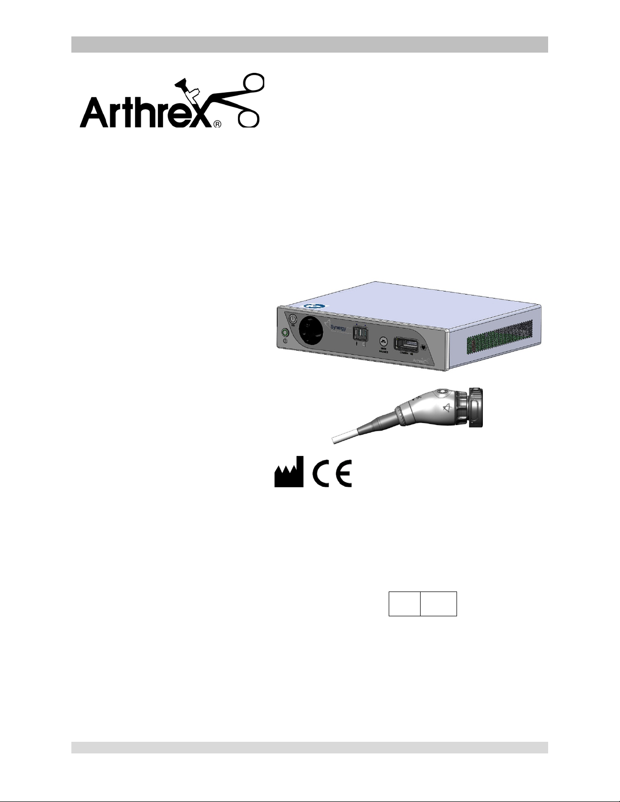
The Arthrex Synergy
Camera Head User’s Guide provides important information
for the safe operation of all components of the Synergy
Camera System, including accessories. Read this User’s
Guide thoroughly prior to using this system and keep it in
an easily accessible place for use by all operating
personnel. Read and follow all safety warnings, cautions
and precautions.
UHD4
System Camera Control Unit and
UHD4
AR-3210-0018
AR-3210-0021
AR-3210-0022
AR-3210-0023
AR-3210-0025
AR-3210-0026
AR-3210-0028
AR-3210-0029
AR-3210-0030
AR-3210-0031
Arthrex, Inc.
1370 Creekside Blvd.
Naples, FL 34108, USA
+1 (800) 934-4404
Technical Support
EC REP
Arthrex GmbH
Erwin-Hielscher-Strasse 9
81249 München, Germany
+49 89 909005-0
AR-3210-0032
950-0047-04A Page 1 of 69

This is not a warranty document. For all warranty information, including disclaimers, exclusi o ns,
terms, conditions, and related provis ions, refer to the “Arthrex U.S. Product Warranty” section of
the Arthrex, Inc. website, found at www.arthrex.com whose provisions are incorporated herein by
reference.
950-0047-04A Page 2 of 69

Table of Contents
1.0 Introduction ...................................................................................................................................... 4
1.1 Intended Use ................................................................................................................................. 4
1.2 Contraindications .......................................................................................................................... 4
1.3 Warnings and Precautions ............................................................................................................ 4
1.4 Symbol Definitions ........................................................................................................................ 9
1.5 End of Life, Environmental Directives ......................................................................................... 11
1.6 Initial Use of the Device .............................................................................................................. 11
1.7 Unpacking and Inspecting the Device ......................................................................................... 12
1.8 Returning the Device .................................................................................................................. 12
1.9 System Indicators ........................................................................................................................ 13
2.0 System Installation and Operation with Data Input Device ............................................................ 20
2.1 Installation .................................................................................................................................. 20
2.2 Accessories for Intended Use ...................................................................................................... 22
2.3 System Setup Facility and Surgeon Settings ............................................................................... 24
2.4 Icon Guide ................................................................................................................................... 33
2.5 Scheduling and Starting Cases .................................................................................................... 35
2.6 Status Notification Icons ............................................................................................................. 42
2.7 System Operation without Tablet Data Input Device ................................................................. 45
3.0 Maintenance ................................................................................................................................... 47
3.1 Life Expectancy............................................................................................................................ 47
3.2 Periodic Maintenance ................................................................................................................. 47
3.3 Cleaning and Sterilizing ............................................................................................................... 48
3.4 Troubleshooting .......................................................................................................................... 52
3.5 Resolving Error Messages ........................................................................................................... 55
3.6 Recommended Annual Camera Control Unit Maintenance Requirements ............................... 55
4.0 Technical Information ..................................................................................................................... 56
5.0 APPENDIX [Radio Module Information] ......................................................................................... 61
6.0 APPENDIX [Detailed EMC Information] ......................................................................................... 62
7.0 APPENDIX [SW Version access] ................................................................................................... 67
950-0047-04A Page 3 of 69

1.0 Introduction
WARNING: The safety and/or health
PRECAUTION: This contains
It is recommended that personnel study this
manual before attempting to operate, clean,
and/or sterilize the Arthrex Synergy
Synergy
safe and effective use of this equipment
requires the understanding of and
compliance with all warnings, precautionary
notices, and instructions marked on the
product, and included in this manual.
The Arthrex Synergy
comprised of:
NOTE: AR-3200-0020/AR-3200-0022
Synergy
UHD4
• AR-3200-0020 [Synergy
with Matrix]
• AR-3200-0021 [Synergy
Console]
• AR-3200-0022 [SynergyUHD4
Console with Matrix, HCRI]
• AR-3200-0023 [SynergyUHD4
Console, HCRI]
• AR-3210-0018 [HD, SynergyUHD4
Camera Head, autoclavable]
• AR-3210-0021 [HD SynergyUHD4
C-Mount Camera Head,
autoclavable]
• AR-3210-0022 [HD SynergyUHD4
C-Mount Camera Head, 0 Degree,
autoclavable]
• AR-3210-0023 [4K SynergyUHD4
Camera Head, autoclavable]
• AR-3210-0025 [4K SynergyUHD4 C-
Mount Camera Head, autoclavable]
• AR-3210-0026 [4K SynergyUHD4 C-
Mount Camera Head, 0 Degree,
autoclavable]
• AR-3210-0028 [4K SynergyUHD4 C-
Mount w/20 foot cable, autoclavable]
• AR-3210-0029 [4K SynergyUHD4
Broadband Camera Head,
autoclavable]
• AR-3210-0030 [4K SynergyUHD4 C-
Mount Broadband Camera Head,
autoclavable]
• AR-3210-0031 [4K SynergyUHD4
Ultra Camera Head, autoclavable]
• AR-3210-0032 [4K S ynerg yUHD 4
Ultra C-Mount Camera Head,
autoclavable]
UHD4
Consoles or Camera Control Units
System and accessories. The
UHD4
System is
UHD4
Console
UHD4
(CCU) are identical to AR-3200-0021/AR-32000023 CCUs except that AR-3200-0020/AR3200-0022
incorporate the Matrix PWA for
transmission of UHD4 data by fiber optic.
1.1 Intended Use
This system is designed for use by
physicians and surgeons and is intended for
endoscopic camera use in a variety of
endoscopic surgical procedures, including
but not limited to, orthopedic, laparoscopic,
urologic, sinuscopic and plastic surgical
procedures. It is also intended to be used as
an accessory for microscopic surgery.
1.2 Contraindications
Do not use the device if endoscopic surgery
is contraindicated.
Do not use the device if the environmental
conditions for use do not meet the standards
or regulations defined in the accompanying
documents.
1.3 Warnings and Precautions
The words WARNING, PRECAUTION, and
NOTE carry special meanings and they should
be read carefully.
of the patient, user, or a third party is
at risk. Comply with this warning to
avoid injury to the patient, user, or
third party.
information concerning the intended
use of the device or accessory.
Damage to the equipment is
possible if these instructions are not
followed.
NOTE: A note is added to provide additional,
focused, information.
1.3.1 WARNINGS
• This equipment is designed for use
by medical professionals com plet el y
familiar with the required techniques
and instructions for use of the
equipment. Prior to using the device,
950-0047-04A Page 4 of 69
read and follow all warning and
precautionary notices and
instructions marked on the product
and included in this manual. Become
familiar with the operation and
function of this device and
associated accessories. Failure to
follow these instructions can lead to:
• Life-threatening injuries to the pati ent
• Severe injuries to the surgical team,
nursing or service personnel, or
• Damage or malfunction of the device
or accessories.
1. Do not open or attempt to service this
system, as this may void your
warranty. There are no userserviceable parts inside. Removing the
cover may introduce an electric shock
hazard by exposing you to dangerous
high voltages or other risks. If the system
malfunctions, return it for service
immediately.
2. For the protection of the patient it is
recommended that a back-up camera system
for the Arthrex Synergy
maintained, sterilized, and ready to be
implemented.
3. For the protection of the patient it is essential
that the endoscopic video system
interconnection is complete and produces a
viable color picture on the surgical monitor
PRIOR to administration of patient
anesthesia.
4. Disconnect camera head and endoscope
from the patient prior to applying cardiac
defibrillation to patient.
5. Only the physician can evaluate the clinical
factors involved with each patient and
determine if the use of this device is
indicated. The physician must determine the
specific technique and procedure that will
accomplish the desired clinical effect.
6. This device and its accessories are to be
used only by physicians and medical
assistants under the direction of a physician
with appropriate technical q ual if icatio ns .
7. This device shall only be used with original
and manufacturer’s accessories
and replacement parts. Use of
UHD4
video system be
other parts or materials may degrade safety.
8. Do not use in the presence of flammable
anesthetics, gases, disinfecting agents,
cleaning solutions, or any material
susceptible to ignition due to electrical
sparking.
9. Equipment grounding is vital for safe
operation. Plug the power cord into a properly
earthed mains supply outlet whose voltage
and frequency characteristics are compatible
with those listed on the unit or in this manual.
Do not use plug adapters or extension cords;
such devices defeat the safety ground and
could cause injury.
10. This equipment should not share an electrical
outlet or grounding with life supporting or life
sustaining equipment.
11. If one or more mains powered units are
connected simultaneously to one socket by
the means of a distribution box, the sum of
the individual leakage currents may exceed
the tolerated limits.
12. Before each use, the outer surface of the
portions of the Endoscope and any
Endoscopically Used Accessory, which are
intended to be inserted into the patient, should
be checked to ensure there are no unintended
rough edges, sharp edges or protrusi ons whic h
may cause a safety hazard.
13. Refer to Insufflation Device Instructions
regarding safety hazards to patients resulting
from gas emboli.
14. The leakage current through the patient could
increase when using endoscopes with
powered accessories.
15. When Endoscopes are used with Energized
Endoscopically Used Accessories, the
Patient Leakage Currents may be additive.
This is particularly true if a CF Applied Part is
used, in which case a Type CF
Endoscopically Used Accessory should be
used to minimize total Patient Leakage
Current.
16. Applied Parts of other ME Equipment used
within the configuration for Endoscopic
Application shall be type BF or CF Applied
Parts.
17. Explosive gas concentrations inside the
patient can cause hazards while using HighFrequency Endoscopically Used Accessories.
950-0047-04A Page 5 of 69

18. For the protection of service personnel, and
for safety during transportation, all devices
and accessories that are returned for repair
must be prepared for shipment as described
in “Returning the Device” of this manual.
The manufacturer has the right to refuse to
carry out repairs if the product is
contaminated.
19. This equipment/system may cause radio
interference or may disrupt the operation of
nearby equipment. It may be necessary to
take mitigation measures, such as re-
UHD4
orienting or relocating the Synergy
Video System or shielding the location.
20. NOT for use in an Oxygen Rich Environment.
21. NO Modifications of this equipment are
allowed.
22. Connecting any equipment that has not been
supplied as part of this ME System to Multiple
Socket Outlets may result in increased
leakage currents. Use an IEC Approved
Isolation Transformer to isolate any such
interconnections from the ME System.
illumination in small cavities, or if the
endoscope’s distal end is placed in
close proximity with the tissue. This can
cause the temperature of the body
tissue to rise in excess of 106 °F (41°C).
Burns or thermal damage to surgical
equipment may also result.
• Avoid prolonged exposure to intense
illumination.
• Use the minimum level of illumination
necessary to satisfactorily illuminate the
target area.
• Do not place the endoscope’s distal end
or light guide connector on the patient’s
skin, on flammable materials or on heat
sensitive materials.
• Turn the light source off when detaching
the endoscope from the light guide
cable.
• Allow the endoscope and light guide
cable to cool down after use before
reprocessing.
23. Before each use or after changing viewing
modes/settings the Operator should check to
ensure that the view observed through the
Endoscope provides a live image (rather than
a stored one) and has the correct image
orientation.
24. Risk of burns!
LED Light Engines emit large amounts of
light and thermal energy. As a result:
• Always keep the LED Li ght Eng ine in
the STANDBY mode when not in use.
The endoscope light guide connection
can get extremely hot as result of high
intensity light, giving rise to high
temperatures in front of the light
emission window which may cause
severe burns.
• Surface temperatures of the insertion
portion of the endoscope as well as light
guide connectors on the Camera
Control Unit (CCU) and the endoscope
rise during use.
• Potential thermal injury to the patient’s
tissue and skin may result from
prolonged exposure to the intense
25. High Frequency [HF] electrical surgical
instruments may lead to severe patient
injuries and/or damage to the endoscope.
Care should be taken to ensure that the
working element is kept within field of view to
prevent accidental burns. A sufficient
distance from the tip of the endoscope to
other conductive accessories and
instruments should be maintained (10 mm)
before activating the HF output to prevent
burns and damage to the endoscope. Refer
to the HF Surgical Device Instructions for
proper and safe use.
26. HF surgical instrum ents m ay interfer e with
video images. To prevent such interference,
HF equipment and video imaging equipment
should be connected to different power
supply circuits.
27. Use of Lasers in surgery may result in Eye
Damage or damage to the endoscope from
reflected laser energy. Refer to the Laser
Device Instructions for proper and safe use.
• When using a laser always wear
protective glasses designed for the
laser’s wavelength.
950-0047-04A Page 6 of 69

• Cover the patient’s eyes, or use
protective glasses designed for the
laser’s wavelength.
• To prevent damage to the
Endoscope, the Laser should be
activated only after the tip of the laser
can be seen through the endoscope.
28. To ensure FCC RF Exposure limits for base
station transmissions devices are met, a
distance of 20 cm or more shall be
maintained between the Camera Control Unit
(which contains the antennas), and persons
during operation. To ensure compliance, an
operator closer than 20 cm to Camera
Control Unit is not recommended.
1.3.2 PRECAUTIONS
1. United States Federal law restricts sale of
this device to or on the order of a physician.
2. Only use the device with Arthr ex compatible
equipment listed in Section 2.2.
3. Inserting an incompatible Camera Head into
the camera receptacle (see Figure 1) can
result in damage to the CCU.
4. The warranty becomes void and the
manufacturer is not liable for direct or
resulting damage if:
• The device or the accessories are
improperly used, prepared or
maintained;
• The instructions in the manual are not
adhered to;
• Non-authorized persons perform
repairs, adjustments or alterations to the
device
• Non-authorized persons open the
device.
NOTE: Receipt of technical documentation
from the manufacturer does not authorize
individuals to perform repairs, adjustments,
or alterations to the device or accessories.
Only authorized service personnel may
perform repairs, adjustments or alterations
on the device and accessories. Any violation
will void the manufacturer’s warranty.
Authorized service technicians are trained
and certified only by the manufacturer. The
Manufacturer will make available on request
circuit diagrams, component part lists,
descriptions, calibration instructions and
other information required for service to any
Arthrex Authorized Service Center.
5. This device should only be used in
compliance with its intended use.
6. Prior to each use, the CCU and all
associated equipment must be inspected for
proper operation. Visually inspect lenses to
ensure there are no scratches, chips or
cracks.
7. To carry out safe operation, it is absolutely
necessary to carry out proper care and
maintenance of the device and acces s ories .
See “Maintenance” section of this manual.
8. Ensure that the available mains voltage
matches the mains voltag e data on the rear
of the device which is located near the
appliance inlet module.
9. This device may only be connected to
endoscopes which, in their intende d use and
technical specifications, are appropriate for
use with the device for the intended medical
procedure. The endoscopes must comply
with the latest version of DIN EN 60601-2-18
and ISO 8600.
10. Do not expose the Camera Control Unit
(CCU) to moisture, or operate it in a wet
area, or store liquids above the CCU.
11. Do not excessively bend or kink instrument
power cord or camera head cable.
12. Handle all equipment carefully. If the CCU or
camera head is dropped or damaged in any
way, return it immediately for service.
13. If the camera head or camera head cable
are damaged in any way, or cable or
connector jacket are cut, do not autoclave
camera head, or immerse camera head in
liquid (water, chemical disinfectants or
sterilants, etc.). Notify your Arthrex Sales
Representative. If it is necessary to return
the camera head to Arthrex for service,
disinfect the camera head before shipping
and reference “Returning the Device”.
14. Store camera head and all accessories in a
protective container to prevent damage
during storage. Do not store CCU where it
950-0047-04A Page 7 of 69

will be exposed to temperatures in excess of
140°F (+ 60°C).
15. Additional equipment connected to medical
electrical equipment must comply with the
respective IEC or ISO standards (e.g. 60950
for data processing equipment).
Furthermore all configurations shall comply
with the requirements for medical electrical
systems (see IEC 60601-1 ). Anybody
connecting additional equipment to medical
electrical equipment configures a medical
system and is therefore responsible that the
system complies with the requirements for
medical electrical systems. Attention is
drawn to the fact that local laws take priority
over the above mentioned requirements. If
in doubt, consult your local representative,
or the technical department.
16. Any person who connects external
equipment to signal i nput and signal output
ports or other connectors has formed a
system and is therefore responsible for the
system to comply with the requirements of
IEC 60601-1. If in dou bt, contact a qual ified
Biomedical technician or your local
representative.
17. This equipment has been tested and found
to comply with the Class A limits for medical
devices to IEC 60601-1-2:. These limits are
designed to provide reasonable protection
against harmful interference in a typical
medical installation. This equipment
generates and can radiate radio frequency
energy and, if not installed and used in
accordance with the instructions , may cause
harmful interference to other device(s) in the
vicinity. However, there is no guarantee that
interference will not occur in a particular
installation. If this equipment does cause
harmful interference to other devices, which
can be determined by turning the equipment
off and on, the user is encouraged to try to
correct the interference by one or more of
the following measures:
(a) Reorient or relocate the receiving
device.
(b) Increase the separation between the
equipment.
(c) Connect the equipment into an outlet on
a circuit different from that to which the
other devices are connected.
(d) Consult the manufacturer or field service
technician for help.
This unit was not evaluated for use with
electrosurgical devices which access the
site via the same endoscope as the light
engine and camera. The unit must be reevaluated prior to use with electrosurgical
devices when they will operate through the
same endoscope as the light source and
camera.
18. After each use, thoroughly clean unit and
accessories (See “Cleaning and
Sterilizing”).
NOTES:
1. Observe all national waste management
regulations.
2. Do not dispose of WEEE as unsorted
municipal waste.
950-0047-04A Page 8 of 69
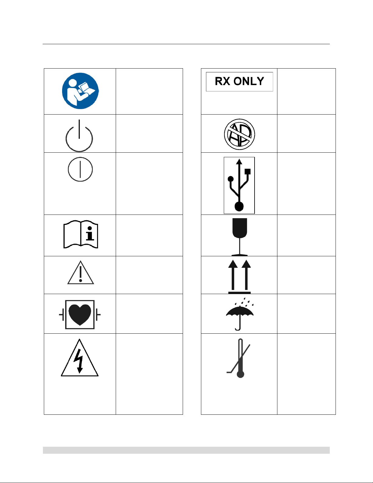
1.4 Symbol Definitions
Physician.
components.
Safety Sign
Follow Operating
Instructions
Power Standby/On
ON-OFF
Push-Push
Attention, Consult
Accompanying
Documents
Caution: Federal
Law Restricts
this device to
sale by or on the
order of a
Not for use in the
Presence of
Flammable
Anesthetics.
USB Tablet
Computer
Connection
Fragile
Precaution of
Warning Notice
Defibrillation Proof
Type CF Equipment
Electrical Hazard,
Dangerous Voltages
are Present. Never
attempt to repair the
equipment. Only
Trained Service
Personnel may
remove the cover, or
obtain access to
system
This Side Up
Keep Dry
Temperature
Limits for
Storage and
Transport
950-0047-04A Page 9 of 69
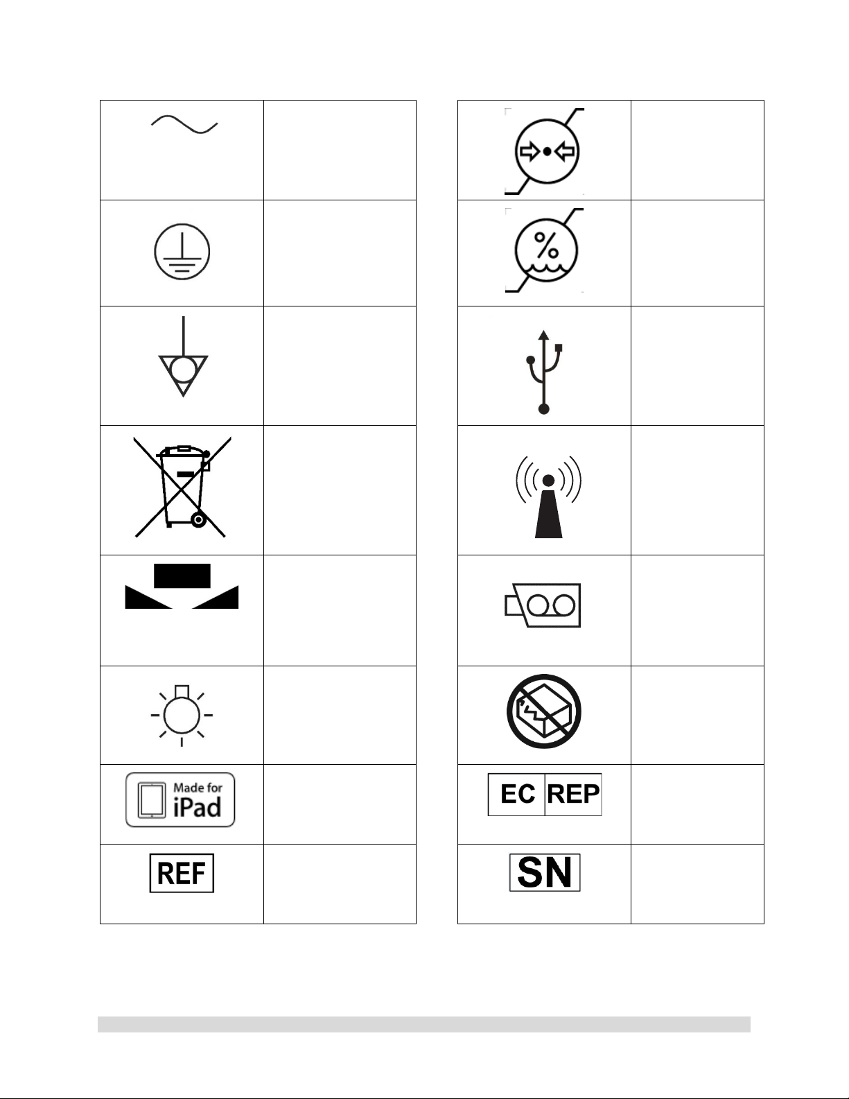
Alternating Current
Equipment] Symbol.
Pressure Limits
for Storage and
Transport
Protective Earth
[Ground]
Equipotential
[Equipment
Potential]
WEEE [Waste
Electronics and
Electrical
Regarding European
Union End-of-Life of
Product.
White Balance
Symbol
Humidity Limits
for Storage and
Transport
Universal Serial
Bus
RF Symbol. Non-
ionizing
Electromagnetic
Radiation
Color Video
Camera
950-0047-04A Page 10 of 69
LED Light
MFi
Made for iPad
Catalog Number
Do Not Use if
Damaged
EC Rep
Serial Number

1.5 End of Life, Environmental Directives
WEEE Directive [2012/19/EU] on Waste
Electrical and Electronic Equipment
The Directive on Waste Electrical and Electronic
Equipment obliges manufacturers, importers,
and/or distributors of electronic equipment to
provide for recycling of the electronic equipment
at the end of its useful life.
Do not dispose of WEEE in unsorted municipal
waste.
The WEEE symbol on the product or its
packaging indicates that this product must not
be disposed of with other waste. Instead, it is
your responsibility to dispose of your waste
equipment by handing it over to a designated
collection point for the recycling of Waste
Electrical and Electronic Equipment. The
separate collection and recycling of your waste
equipment at the time of disposal will help
conserve natural resources and ensure that it is
recycled in a manner that protects human health
and the environment. For more information
about where you can drop off your medical
endoscopic video equipment at the end of its
useful life for recycling, please contact Arthrex
Customer Service Department.
The Camera Control Unit (CCU)
contains a Lithium Coin BATTERY. The
BATTERY must be recycled or disposed
of properly.
NOTE for State of California, USA:
State of California Requirement: Lithium
Batteries contain Perchlorate Material -special
handling may apply. See
www.dtsc.ca.gov/HazardousWaste/Perchlorate
In the US a list of recyclers in your area can be
found at www.eiae.org/
1.6 Initial Use of the Device
WARNINGS:
1. The device is only completely isolated
from the mains if the power plug is
disconnected from the device’s power
inlet module. Avoid positioning
equipment such that removal of plug is
difficult.
2. The electrical installation of the operating
room where the device is used must
comply with applicable national
requirements.
3. Loss of the Mains Voltage may result in
an unacceptable risk due to loss of
Clinical Function. An Uninterruptable
Power Supply [UPS] is recommended to
mitigate this risk.
4. The device is not intended for use in
areas of explosion hazards. If explosive
nitrous gases are used the Camera
Control Unit may not be operated in the
danger zone.
5. Do not simultaneously touch the Camera
Control Unit and the patient. Camera
Control Unit is intended to be used
outside the Patient Vicinity.
6. Additional peripheral equipment
connected as part of the Endoscopic
Video System must meet the
requirements of the following
specifications:
• IEC 60950 for Information
Technology Equipment.
• IEC 60601-2-18 for endoscopic
devices.
• IEC 60601-1 for medical electrical
equipment.
7. All final Endoscopic Video Systems m ust
meet the requirements of IEC 60601-1.
8. Whoever connects additional equipment
to signal input or signal output is
obligated to meet the requirements of the
IEC 60601-1 standard.
950-0047-04A Page 11 of 69

CAUTION: Do not install the device
in a location near heat sources such
as air ducts or radiators and do not
expose the device to direct sunlight,
excessive dust, or mechanical vibration.
1.7 Unpacking and Inspecting the Device
Upon receipt, carefully unpack the Synergy
Camera Control Unit (CCU) and accessories.
Ensure contents are complete and are free from
damage. If any damage is noted contact your
Arthrex Customer Service. Contact the
Manufacturer for Return Authorization PRIOR to
shipping your device for service. Save ALL
packaging materials; they may be needed to
verify any claims of damage by the shipper.
UHD4
1.8 Returning the Device
If it becomes necessary to return the device,
always use the original pack aging. T he
manufacturer does not take responsibility for
damage that has occurred during transportation
if the damage was caused by inadequate
transport packaging. Please make sure that all
required information has been supplied. Call
Arthrex for an RMA Number for the device return
for service.
• Owner’s Name
• Owner’s Address
• Owner’s Daytime Telephone Number
• Device type and model.
• Serial Number
• Detailed explanation of the damage.
NOTE:
1. The CCU shall be cleaned per
section Cleaning and
Sterilization prior to returning for
service.
2. The Camera Head shall be
cleaned and Sterilized per
Cleaning and Sterilization p rior
to returning for service. Camera
Head shall be clearly labeled as
“Sterile.”
Equipment will not be repaired unless
decontaminated as stated abo ve prior to return
to the manufacturer.
950-0047-04A Page 12 of 69
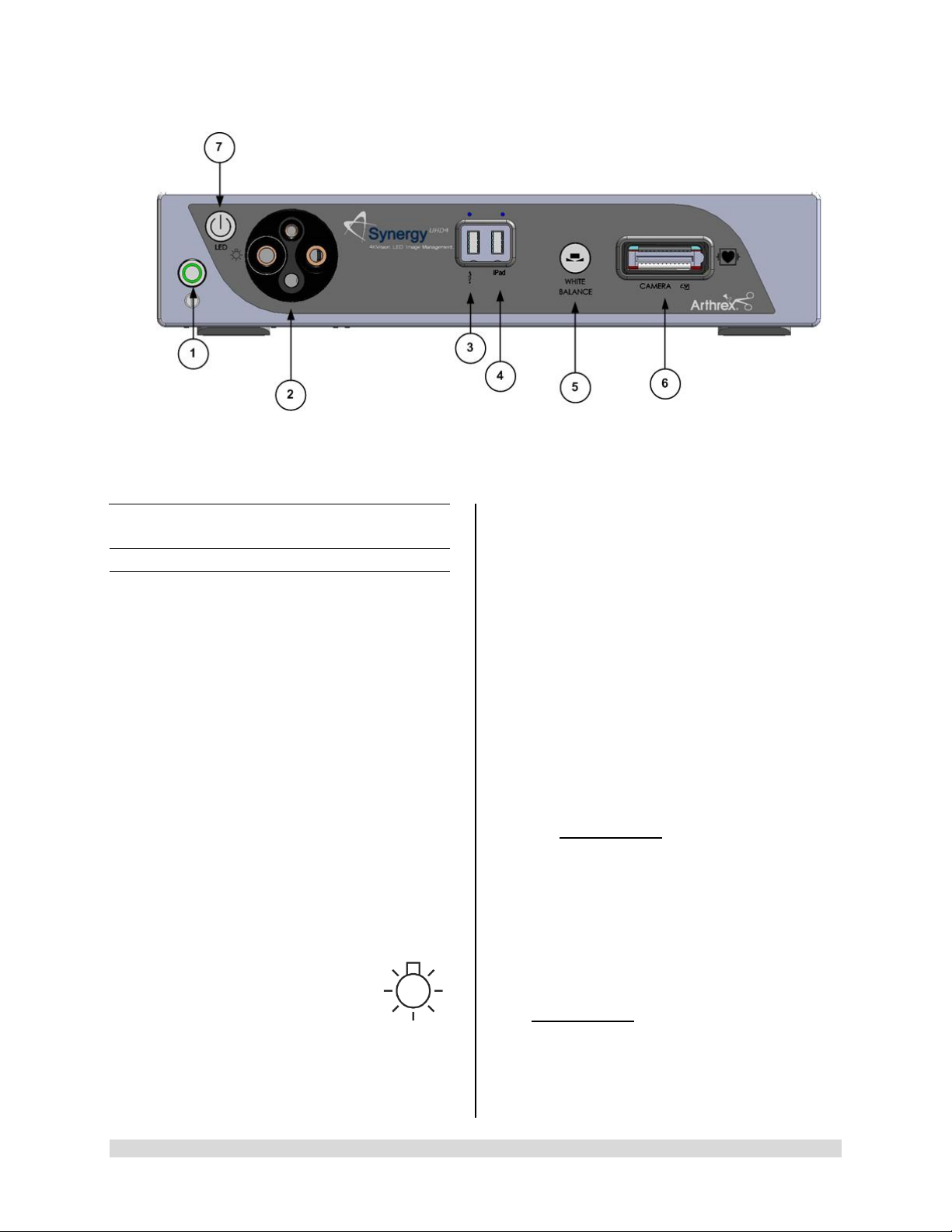
Figure 1- Synergy
UHD4
1.9 System Indicators
UHD4
1.9.1 Synergy
1. On/Standby Switch-The On/Standby switch
toggles the Camera Control Unit (CCU)
between ON [operational mode] and
STANDBY. The Green LED will illuminate
when the CCU is in the ON mode. Press and
HOLD the switch to toggle between ON and
STANDBY.
2. Light Guide Turret-Turret for Light Guide
input
Front Panel
• Wolf Input
• Storz Input
• ACMI Input
• Olympus Input
NOTE: Rotate Light Guide Turret until the
appropriate port is aligned with LED
INDICATOR then Insert
Light Guide.
Front Panel [AR-3200-002x]
3. USB Port-Connect USB devices here.
4. iPAD USB Port-Connect iPAD to this port.
5. “WHITE BALANCE” Button-Press to initiate
camera white balance.
6. “CAMERA” Input Connection-Insert the
camera head connector here. The camera
head connector and rec eptacle are sp ecially
keyed to prevent the camera head from being
improperly connect ed. Ensure that the “U P”
label on the camera head connector is facing
upwards when the camera head connector is
inserted.
PRECAUTION: Ensure camera head
contacts are clean and dry a nd cooled
15 minutes prior to insertion.
7. LED Light Engine On/Standby Switch-The
Light S ource On/Standb y Switch to ggles the
Light Source between ON [Operational
Mode] and STANDB Y.
PRECAUTION:
Use only FUSED Light Guides to ensure
proper operation of LED Light Engine.
950-0047-04A Page 13 of 69
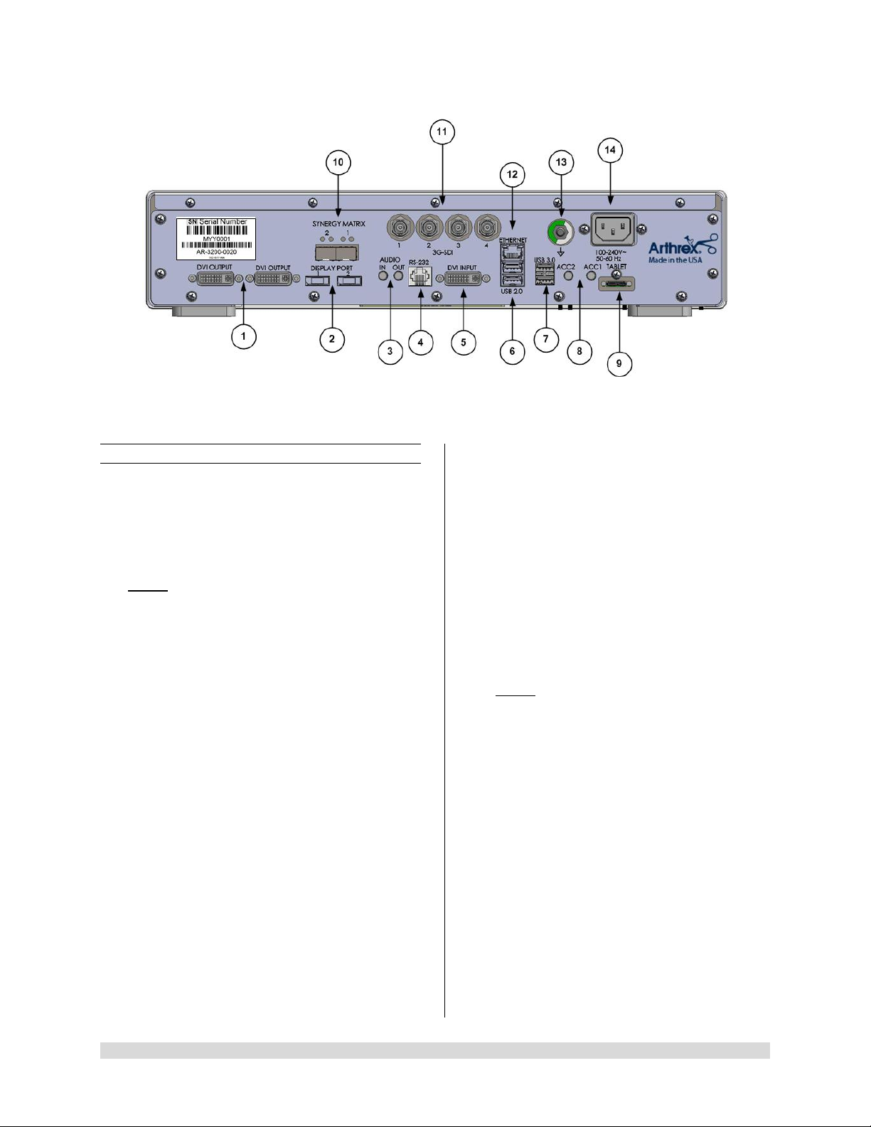
Figure 2- Synergy
1.9.2 Rear Panel
1. “DVI” Video Output Connectors-Supplies a
digital video signal output in DVI-D format.
2. Display Ports (2X)-Supplies UHD Video
Signal output in either 1.1 [dual cable] or 1. 2
[MST].
NOTE: Arthrex recommends connecting
Synergy
UHD4
to the primary surgical monitor via
multiple output types (e.g., display port and
DVI, Synergy Matrix a nd 3G-SDI) in the event
that one type of connection is lost.
3. Audio In / Audio Out-Audio In: Line Level
Audio input for Microphone. Audio Out: Line
Level Audio output to Medical Grade Devices.
4. RS-232 Connector-Isolated connection to
devices requiring Serial Contr ol.
5. DVI Input-1080P/60 Input for Picture in Picture
[PIP].
6. USB 2.0 (2X)-USB 2.0 Connection.
7. USB 3.0 (2X)-USB 3.0 Connection.
8. Accessory Ports (Inputs/Outputs (2X) mini
Stereo-Phone Connectors)-Accessory ports
allow for control of the CC U with a footswitch
or external device or for the CCU to control
external devices via the camera head buttons.
9. Tablet Connection-Connection for Tablet
Data Input device. Provides for data
interchange and tablet charging.
UHD4
Rear Panel
10. Synergy Ma tr ix [Synergy Matrix Only]-Fiber
Optic output to Matrix Monitor (point to point or
managed) via Custom SFP+ Fiber
Transceivers. Use Output 1 and 2 for 4K Video.
Custom SFP+ Fiber Transceivers and Matrix
License may be obtained from Arthrex
Customer Service.
11. 3G-SDI Out-1080P/60 Output.
12. Ethernet Connector-Isolated 10/100 Mb/sec.
13. Potential Equalization Connector (POAG)-
Potential Equalization Connector per DIN
42801.
NOTE: The purpose of the Potential
Equalization Connector is to equalize the
potentials between diff erent met al parts of the
various Medical Electrical [ME] equipment
which make up a Medical Electrical system, or
to reduce differences of potential which can
occur during oper ation between th e bodies of
the Medical Electrical devices and conduct ive
parts of other objects. The Potential
Equalization Connector may be connected
directly between any ME Devices, or to a
common busbar of the electrical installation.
Reference IEC 60601-1 for ME Systems.
14. IEC 320 Power Inlet Module (100-240V~,
50/60 Hz)-The CCU is equipped with a
switching power supply that automatically
adjusts to the line voltage being used. Accepts
the supplied hospital grade power cord.
950-0047-04A Page 14 of 69
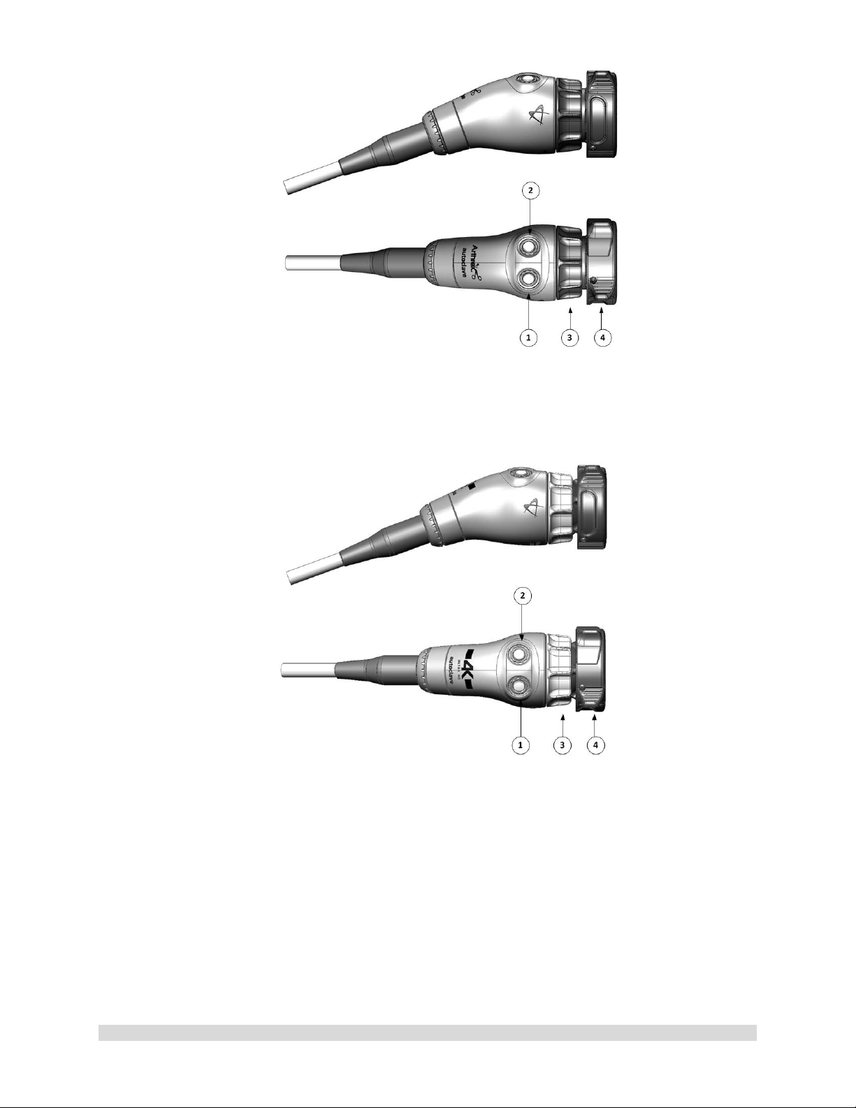
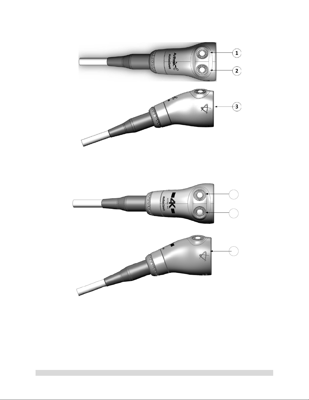
Figure 3- AR-3210-0023 4K SynergyUHD4 Camera Head, autoclavable
Figure 4- AR-3210-0029 4K SynergyUHD4 Broadband Camera Head, autoclavable
950-0047-04A Page 15 of 69
1
2
3
4
Figure 5-AR-3210-0018 HD, SynergyUHD4 Camera Head, autoclavable
Figure 6-AR-3210-0031 4K Ultra SynergyUHD4 Camera Head, autoclavable
1.9.3 Camera Heads with Integrated Optics
1. Button 1-A programmable button that
can activate various functions of the
camera. See “Optional T abl et Dat a Inp ut
Device” for programming information.
2. Button 2-A programmable button that
can activate various functions of the
camera. See “Optional Tablet Data Input
3. Focus Ring-Used to sharpen, or bring
into focus, the image detail.
4. Grasping Mechanism-Accepts and
locks into place the compatible scope.
DIN 58105 compliant endoscope
interface.
Device” for programming information.
950-0047-04A Page 16 of 69
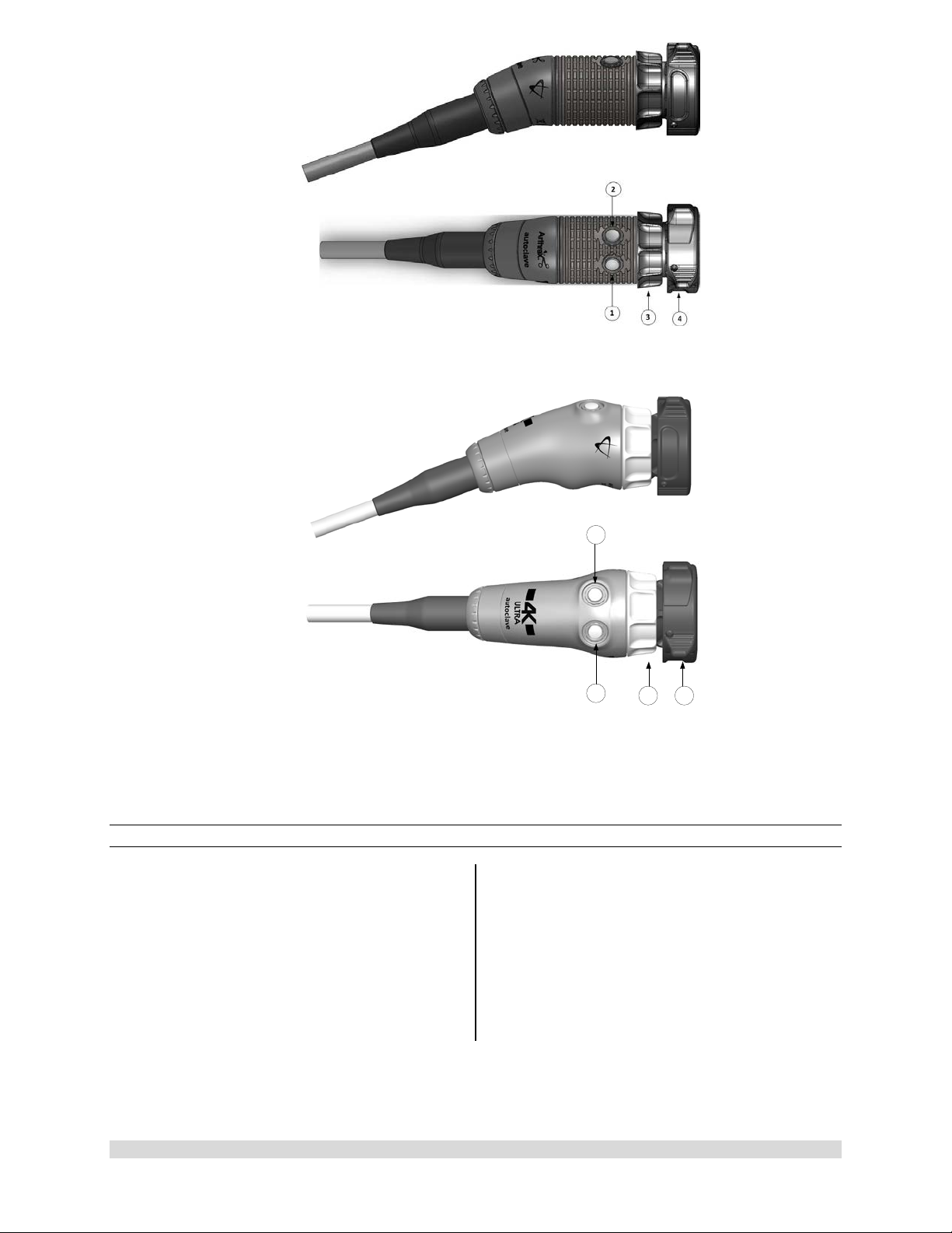
1
2
3
Figure 7-AR-3210-0025 4K SynergyUHD4 C-Mount Camera Head, autoclavable, AR-3210-0028 4K
SynergyUHD4 C-Mount w/20 foot cable, autoclavable and
Not Pictured AR-3210-0026 4K SynergyUHD4 C-Mount Camera Head, 0 Degree, autoclavable
Figure 8-AR-3210-0030 4K SynergyUHD4 C-Mount Broadband Camera Head, autoclavable
950-0047-04A Page 17 of 69
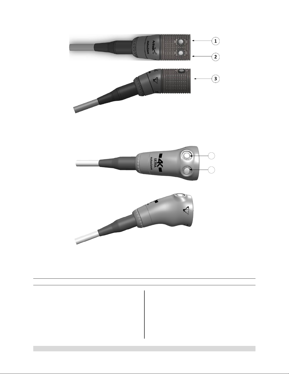
1
2
Figure 9- AR-3210-0021 HD SynergyUHD4 C-Mount Camera Head, autoclavable, and Not Pictured
AR-3210-0022 HD SynergyUHD 4 C-Mount Camera Head, 0 Degree, autoclavable
Figure 10- AR-3210-0032 [4K Ultra SynergyUHD4 C-Mount Camera Head, autoclavable]
1.9.4 C-Mount Camera Heads
1. Button 1-A programmable button that
can activate various functions of the
camera. See “Optional Tablet Data Input
Device” for programming information.
2. Button 2-A programmable button that
can activate various functions of the
camera. See “Optional Tablet Data Input
Device” for programming information.
3. C-Mount Threads-Accepts standard CMount Optical Couplers.
950-0047-04A Page 18 of 69
950-0047-04, Rev. A English
AR-3210-XXXX Camera Head SynergyUHD4 Firmware Compatibility
CAUTION:
• Som e AR -3210-XXXX camera heads are only compatible with specific SynergyUHD4
firmware versions as shown in the following table. Attempting to use these camera heads
with incompatible SynergyUHD4 firmwar e may fail to produce an acceptable quality vide o
output on the surgical display.
Camera Head Compatible SynergyUHD4
Firmware Version
AR-3210-0029 850-0026-01-A or higher
AR-3210-0030 850-0026-01-A or higher
AR-3210-0031 850-0026-02-B or higher
AR-3210-0032 850-0026-02-B or higher
All other camera head models
mentioned in this IFU
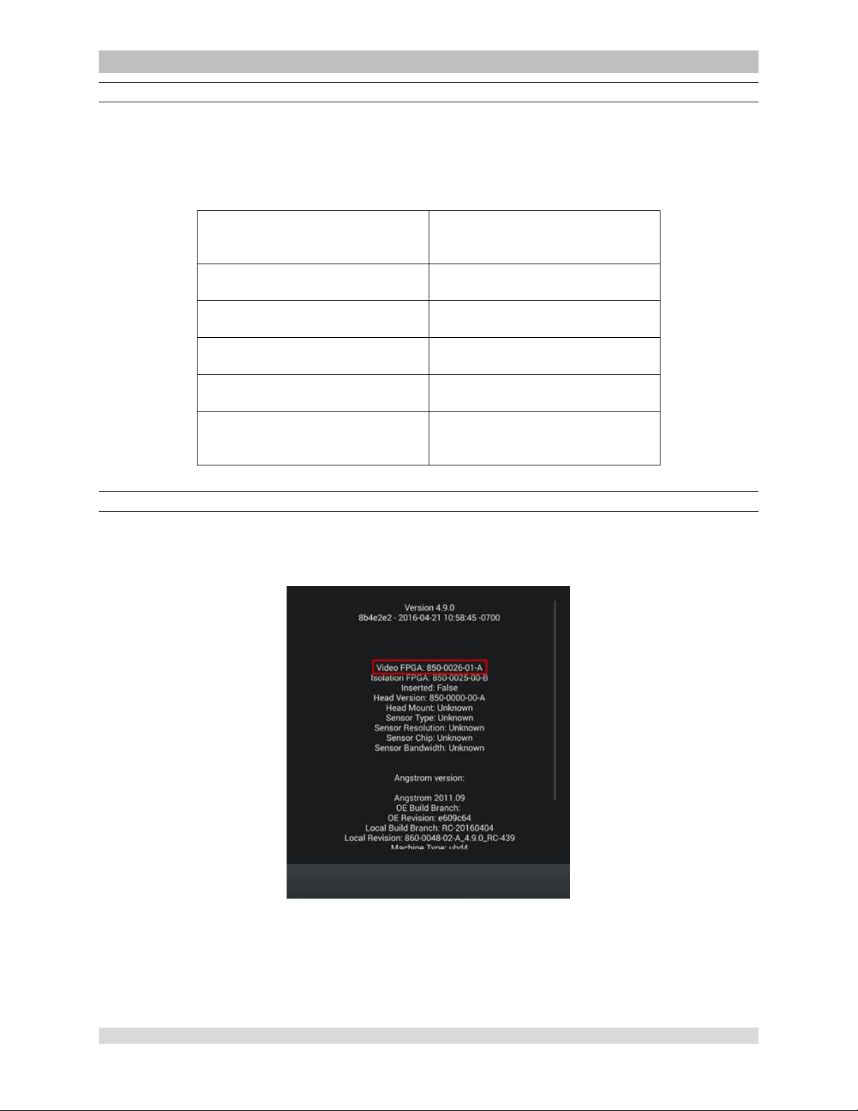
Determining the Firmware Version of the Sy nergyUHD4 System
Firmware can be verified on the About screen, which is accessed by double tapping on the open blue
area of the home login screen and tapping the About option. The firmware version is listed under Video
FPGA as seen in the image below.
All versions
Figure 11- SynergyUHD4 Firmware Version
950-0047-01A Page 19 of 69

2.0 System Installation
and Operation with
Data Input Device
2.1 Installation
1. Your Synergy
indicate which software configuration is
enabled at boot up on the Vid eo Mon itor ’s
Splash screen.
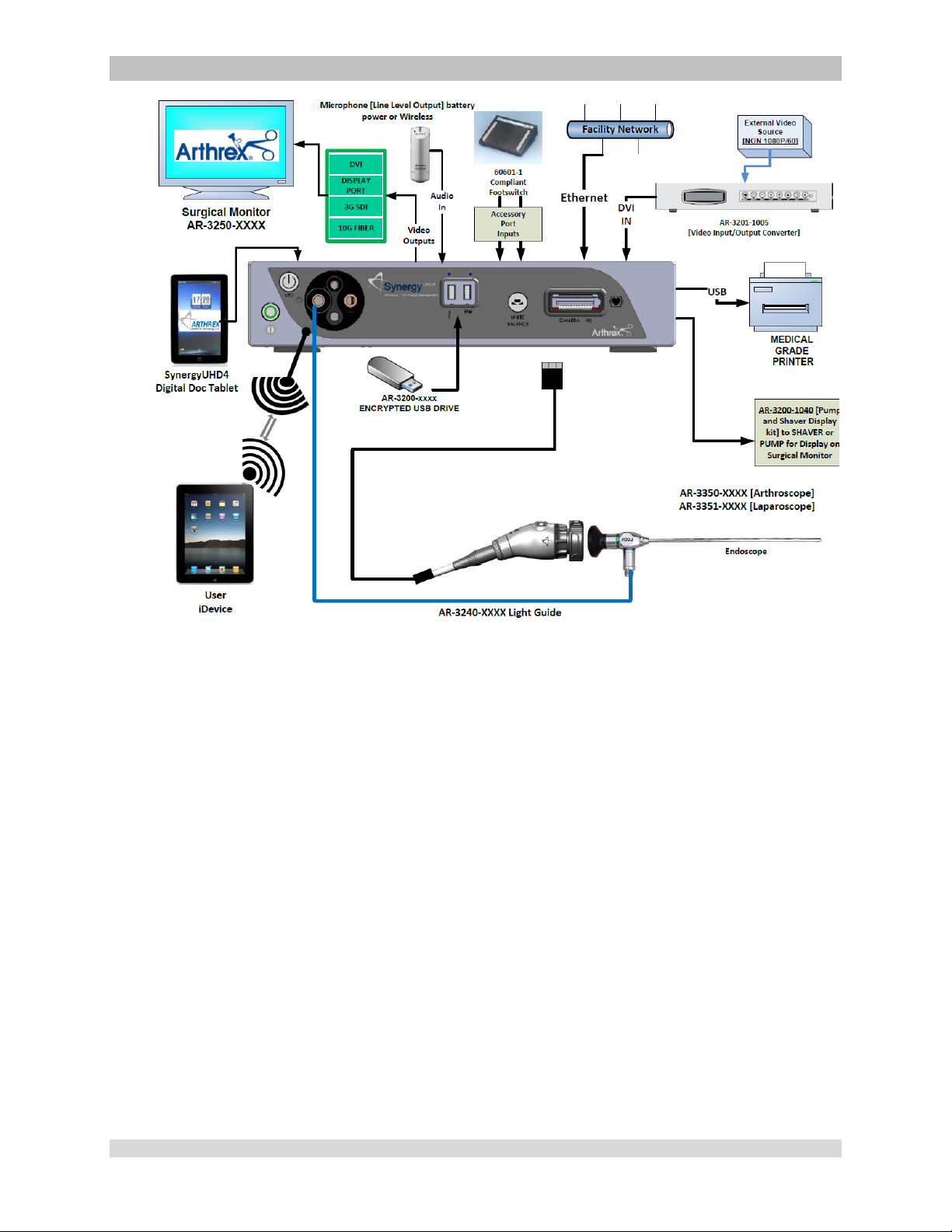
2.1.1 Typical System Installation
NOTE: See Typical Interconnect Diagram,
Figure.
NOTE: Synergy
tower or on an equipment boom.
1. Place Synergy
(CCU) on tower shelf or installed on
equipment boom.
2. Attach monitor to the tower or equipment
boom and connect monitor DC power cable
to the rear panel of the monitor as shown.
3. Attach Synergy
secondary tower arm or equipment boom.
Connect the cable from the Data Input
Device to the connector labeled “tablet” on
the back of the Synergy
4. Connect a Display Port cable to a Display
Port output on the rear panel of the
Synergy
of the Displa y Port cab le to the D ispl a y Port
input of the display monitor. (3G-SDI or D VI
cables may be used instead of Display Port
cables.) Note: Arthrex recommends
connecting Synergy
UHD4
Camera Control Unit will
UHD4
may be installed in a
UHD4
Camera Control Unit
UHD4
Data Input Device to
UHD4
CCU.
UHD4
CCU. Connect the other end
UHD4
to the primary
surgical monitor via multiple output types
(e.g., Display Port and DVI, Displa y Port and
3G-SDI) in the event that one type of
connection is lost.
5. If using a printer, connect the printer cable to
the USB connector on the rear panel of the
UHD4
Synergy
CCU. Connect the other end
of printer cable to the printer.
6. Plug the AC power cord into the
UHD4
Synergy
power inlet module and a
standard grounded AC Mains outlet (100240 V˜, 50-60Hz).
7. Insert the card edge connector of the
UHD4
Synergy
camera head into the camera
receptacle on the front of the CCU. Ensure
the camera had connector contacts are clean
and dry prior to insertion.
WARNING: Inserting an incompatible
Camera Head into the camera receptacle
(see Figure 1) can result in damage to the
CCU.
8. Connect the Light Guide cable into the Light
Guide receptacle on the front panel of the
UHD4
Synergy
CCU. Attach the other end of
the Light Guide cable to the endoscope.
9. Insert the endoscope into the Synergy
UHD4
camera head grasping mechanism or into
the C-Mount Coupler for C-Mount Heads.
10. Press the LED Light Engine On/Standby
Switch to activate the LED light engine.
NOTE: If there is no Light Guide cable
connected to the Synergy
UHD4
CCU,
pressing the On/Standby Switch will no t
activate the LED light engine until one is
connected.
950-0047-04A Page 20 of 69
950-0047-04, Rev. A English
Figure 12- Synergy
Documentation Tablet [Integrated Optics Heads]
UHD4
Typical Interconnect Diagram With OPTIONAL Digital
950-0047-01A Page 21 of 69
 Loading...