

Arthrex 300 User Manual
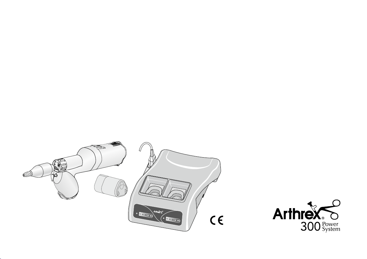
Instructions for use

Contents
Arthrex Symbols ....................................................................................................................................................................3
1. Introduction ........................................................................................................................................................................6
2. Electromagnetic compatibility (EMC) ................................................................................................................................8
3. System overview .............................................................................................................................................................14
4. System components ........................................................................................................................................................ 15
5. Safety notes ....................................................................................................................................................................18
6. Description of handpiece drive ........................................................................................................................................ 24
7. Description of charging station – front side ..................................................................................................................... 25
8. Description of charging station – reverse side ................................................................................................................ 26
9. Description of rechargeable battery ................................................................................................................................27
10. Start-up – charging station ............................................................................................................................................ 28
11. Start-up – handpiece drive ............................................................................................................................................29
12. Removing the rechargeable battery .............................................................................................................................. 30
13. Start-up – Assembling / removing the adaptor ............................................................................................................... 31
14. Changing the rotary instruments and saws .................................................................................................................32
15. Cleaning and maintenance ...........................................................................................................................................37
16. Accessories ...................................................................................................................................................................42
17. Service ..........................................................................................................................................................................43
18. Technical Data ...............................................................................................................................................................45
19. Recycling and disposal .................................................................................................................................................47
Authorized service partner ..................................................................................................................................................48
TRAINING CERTIFICATE ...................................................................................................................................................49
2
Arthrex Symbols
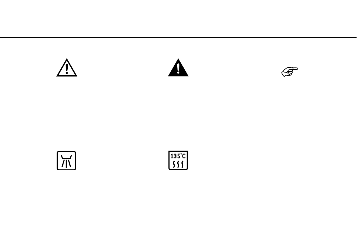
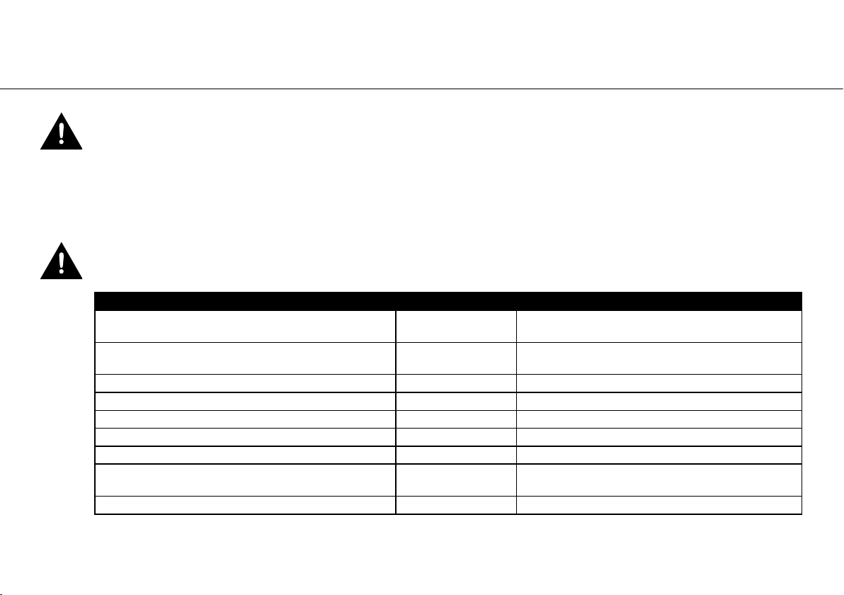
Symbols in the Instructions for use
WARNING!
(Risk of injury)
Thermo washer disinfectable
ATTENTION!
(To prevent damage occurring)
Sterilizable
up to the stated temperature
General explanations,
no risk to persons or objects
3
Arthrex Symbols
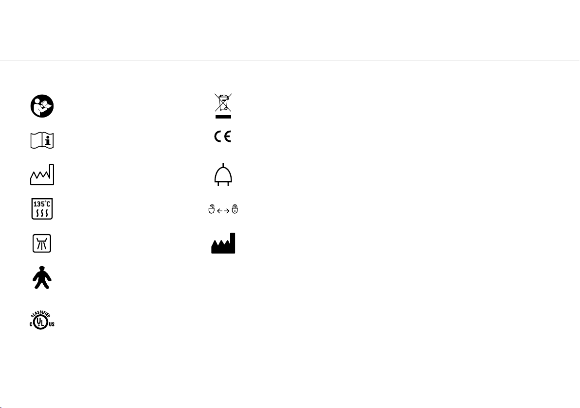
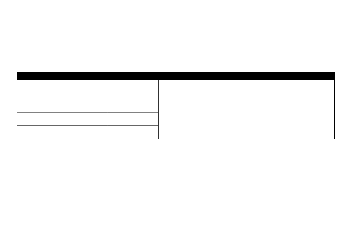
Symbols on the System components
Consult instructions for use
Follow instructions for use
Date of manufacture
Sterilizable
up to the stated temperature
Thermo washer
disinfectable
Not suitable for intracardiac
application –Type B
MEDICAL – GENERAL MEDICAL EQUIPMENT AS TO ELECTRICAL
SHOCK, FIRE AND MECHANICAL HAZARDS ONLY IN
ACCORDANCE WITH ANSI/AAMI ES60601-1 (2005)
CAN/CSA-C22.2 No. 60601-1 (2008)
File No. E365949 and UL 60601-1:1990 / CSA C22.2 NO. 601.1
File No. E365830
4
Do not dispose of
with domestic waste
CE 0086
from the manufacturer
Connecting plug
Lock open / closed
Manufacturer
REF
SN
V
AC
Wh
rpm
Part number
Serial number
Battery voltage
Alternating current
Energy quantity
Revolutions per minute
(rpm = min
-1
)
Arthrex Symbols
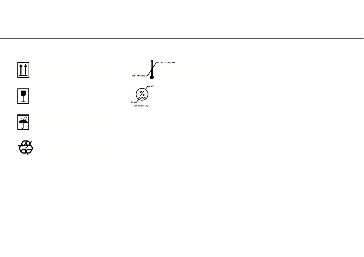
Symbols on the System components
This way up
Fragile, handle with care
Temperature
limits
Humidity
limitation
Keep away from rain
R
General symbol for
E
Y
recovery / recyclable
5

1. Introduction
For your safety and the safety of your patients
These instructions explain to you how to handle your product. However, we must also warn against possible hazardous
situations. Your safety, the safety of your team, and of course, the safety of your patients is of paramount importance to us.
It is therefore essential to read the safety notes on pages 18 to 23.
Intended use
The Arthrex 300 system is a modular electric system, consisting of a handpiece drive, various accessories, and a
charging station for machining bones.
It can be used in the following areas of application: orthopaedic and A&E interventions, such as osteotomies, large and
small bone operations, and joint replacement operations.
The charging station is intended exclusively for charging AR-600L and AR-300L rechargeable batteries.
Misuse can damage the Arthrex 300 system and hence cause risks and hazards for patients, users and third parties.
Qualifications of the user
The Arthrex 300 system may only be used by medically trained, experienced, expert staff, and only once these staff
have been briefed. The target group we had in mind when developing and designing the Arthrex 300 system was
orthopaedic and A&E surgeons and physicians.
Contraindications
• Use by unskilled/untrained personnel
• Disregarding of the intended use
• Non-compliance with the operation mode
• usage of improper accessories
6

Introduction
Production according to EU directive
This medical product has been designed and manufactured according to EU Directive 93/42/EEC
and is valid for the Arthrex 300 system, consisting of:
• AR-300 Handpiece
• AR-300L Battery Pack, Li-Ion
• AR-300LBH Battery Housing
• AR-300ATK Transfer Kit
• AR-300/600 Charging Station
• AR-300SAG Saw Attachment –
Sagittal
• AR-300SR Saw Attachment – Reciprocating
• AR-300B Burr Attachment 2.35 mm
• AR-300RAO Reamer Attachment – Style AO
• AR-300RJ Reamer Jacobs Chuck 0-4.0 mm
• AR-300CA Offset Adapter
• AR-300DAO-1 Drill Attachment – Style AO
• AR-300DK30 Drill Keyless Chuck 0-3.0 mm
• AR-300DK45 Drill Keyless Chuck 2.0-4.5 mm
• AR-300DJ Drill Jacobs Chuck 0-4.0 mm
• AR-300DAO-2 Drill Attachment – Style AO
• AR-300DJH Drill Jacobs Chuck Hybrid
0-5.0 mm
• AR-300WD16 Wire Driver Attachment
0.6-1.6 mm
• AR-300PD24 Pin Driver Attachment
1.0-2.4 mm
in the condition as delivered by us. This declaration is not valid for unintended external or internal attachments
and the like.
Responsibility of the manufacturer
The manufacturer can only accept responsibility for the safety, reliability and performance of the Arthrex 300
system when it is used in compliance with the following directions:
• The Arthrex 300 system must be used in compliance with these Instructions for use.
• The Arthrex 300 system contains no parts which are repairable by the user. Assembly, modifications or repairs
must be carried out only by Arthrex accredited specialists (see page 48).
• Unauthorized opening of the equipment invalidates all claims under warranty and any other claims.
7
2. Electromagnetic compatibility (EMC)
Notes on electromagnetic compatibility (EMC)
Medical electrical equipment is subject to particular precautions with regards to EMC and must be installed and
put into operation in accordance with the EMC notes included.
Arthrex guarantees the compliance of the device with the EMC requirements only when used with original
Arthrex accessories and spare parts. The use of other accessories/other spare parts can lead to an increased
emission of electromagnetic interference or to a reduced resistance against electromagnetic interference.
The use of cables, power supplies, accessories other than those specified by the manufacturer may result in
increased emission and/or decreased immunity.
Cable and accessories Length Reference
AR-600 Li-Ion battery (AR-600L) -
AR-300 Li-Ion battery (AR-300L) -
mains cable (EU) AR-300/600F-EU 3.0 m [9.8 ft] Manufacturer: Feller GmbH [REF 01343700]
alternative mains cable (DK) AR-300/600F-DK 3.0 m [9.8 ft] Manufacturer: Feller GmbH [REF 05901800]
alternative mains cable (UK) AR-300/600F-UK 2.5 m [8.2 ft] Manufacturer: Feller GmbH [REF 03212700]
alternative mains cable (CH) AR-300/600F-CH 2.5 m [8.2 ft] Manufacturer: Feller GmbH [REF 04280600]
alternative mains cable (AUS, NZL) AR-300/600F-AUS 2.5 m [8.2 ft] Manufacturer: Feller GmbH [REF 02909300]
mains cable, hospital grade (USA)
AR-300/600F-US
mains cable (BR) AR-300/600F-BR 2.5 m [8.2 ft] Manufacturer: Feller GmbH [REF 05333500]
3.1 m [10.2 ft] Manufacturer: Feller GmbH [REF 02821400]
Manufacturer: Arthrex GmbH
Producer: W&H [REF 30131]
Manufacturer: Arthrex GmbH
Producer:W&H [REF 30154]
Operate the product in a place with a maximum distance to electrical and magnetic interfering transmitters.
8
If operation of the product close to other devices or together in a stack is necessary, observe the correct
function of the system.
Electromagnetic compatibility (EMC)
Manufacturer’s declaration – Electromagnetic Emission (Table 201, EN 60601-1-2)
The product is suitable for use in a specific electromagnetic environment. The customer and/or the user of the
product should assure that it is used in an electromagnetic environment as described below.
Emission test Compliance Electromagnetic Environment Guidance
RF-emission
CISPR 11
RF-emission
CISPR 11
Harmonic emissions
IEC 61000-3-2
Voltage fluctuations / flicker emissions
IEC 61000-3-3
Group 1
Class B
complies
complies
The product use RF energy only for its internal function. Therefore, it’s RF
emissions are very low and not likely to cause any interference in nearby
electronic equipment.
The product is suitable for use in all establishments, including domestic
establishments and those directly connected to the public low-voltage power
supply network that supplies buildings used for domestic purpose.
9

Electromagnetic compatibility (EMC)
Manufacturer’s declaration – Electromagnetic Immunity I (Table 202, EN 60601-1-2)
The product is suitable for use in a specific electromagnetic environment. The customer and/or the user of the product
should assure that it is used in an electromagnetic environment as described below.
Immunity Test IEC 60601-Level Compliance Level Electromagnetic Environment Guidance
Electrostatic discharge (ESD)
IEC 61000-4-2
Electrical fast transient/bursts
IEC 61000-4-4 (AR-300/600
only)
Surge
IEC 61000-4-5 (AR-300/600 only)
Voltage dips, short interruptions
and voltage variations on power
supply input lines
IEC 61000-4-11 (AR-300/600
only)
Power frequency (50/60 Hz)
magnetic field
IEC 61000-4-8
Note: UT is the mains (AC) voltage before apply test levels
± 6 kV contact
± 8 kV air
± 2 kV for power supply lines
± 1 kV for input/output lines
± 1 kV differential mode
± 2 kV common mode
<5% UT (<95% dip in UT)
for 0.5 cycle
<40% UT (<60% dip in UT)
for 5 cycles
<70% UT (<30% dip in UT)
for 25 cycles
<5% UT (<95% dip in UT)
for 5 sec
3A/m 3A/m
± 6 kV contact
± 8 kV air
± 2 kV for power supply lines
± 1 kV for input/output lines
± 1 kV differential
± 1 kV differential mode
± 2 kV common mode
<5% UT (<95% dip in UT)
for 0.5 cycle
<40% UT (<60% dip in UT)
for 5 cycles
<70% UT (<30% dip in UT)
for 25 cycles
<5% UT (<95% dip in UT)
for 5 sec
Floor should be wood, concrete or ceramic tile.
If floors are covered with synthetic material, the
relative humidity should be at least 30 %
Mains power quality should be that of a typical
commercial and/or hospital environment
Mains power quality should be that of a typical
commercial and/or hospital environment
Mains power quality should be that of a typical
commercial and/or hospital environment. If
the user of the product requires continued
operation during power mains interruptions, it is
recommended that the product be powered from
an uninterruptible power supply.
Power frequency magnetic fields should be at
levels characteristic of a typical location in a
typical commercial or hospital environment.
10
Electromagnetic compatibility (EMC)
Manufacturer’s declaration – Electromagnetic Immunity II (Table 204, EN 60601-1-2)
The product is suitable for use in a specific electromagnetic environment. The customer and/or the user of the product
should assure that it is used in an electromagnetic environment as described below.
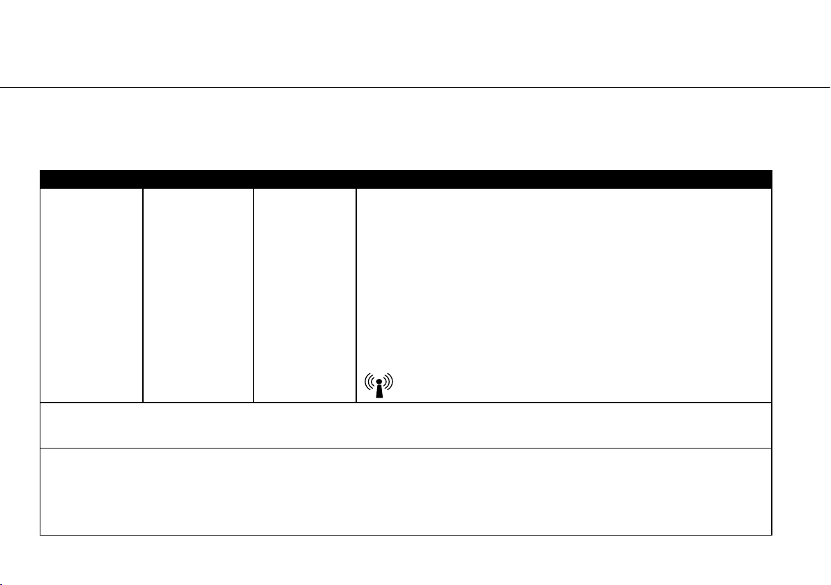
Immunity Test IEC 60601-Level Compliance Level Electromagnetic Environment Guidance
Conducted RF
IEC 61000-4-6
rms
3 V
150 kHz to 80 MHz
(AR-300/600 only)
Radiated RF
IEC 61000-4-3
3 V/m
80 MHz to 2.5 GHz
Note 1: At 80 MHz and 800MHz, the higher frequency range applies.
Note 2: These guidelines may not apply in all situations. Electromagnetic propagation is affected by absorption and reflection from structures,
objects, people and animals.
a
Field strengths from fixed transmitters, such as base stations for radio (cellular/cordless) telephones and land mobile radios, amateur radio, AM
and FM radio broadcast and TV broadcast cannot be predicted theoretically with accuracy. To assess the electromagnetic environment due to
fixed RF transmitters, an electromagnetic site survey should be considered, if the measured field strength in the location in which the product
is used exceeds the applicable RF compliance level above, the product should be observed, additional measures may be necessary, such as
reorienting or relocating the product.
b
Over the frequency range 150 kHz to 80 MHz, field strengths should be less than 3 V/m.
3 Vrms
3 V/m
Portable and mobile RF communications equipment should be used no closer to
any part of the product, including cables, than separation distance calculated from
the equation applicable to the frequency of the transmitter.
Recommended separation distance:
d=1.2√P
d=1.2√Pfor80MHzto800MHz
d=1.2√Pfor800MHzto2.5GHz
where P is the maximum output power rating of the transmitter in Watt (W)
according to the transmitter manufacturer and d is the re-commended separation
distance in meters (m).
Field strengths from fixed RF transmitters, as determined by an electromagnetic
site survey
a
, should be less than the compliance level b in each frequency range.
Interference may occur in the vicinity of equipment marked with the
symbol described lateral.
11
Electromagnetic compatibility (EMC)
Manufacturer’s declaration – Electromagnetic Immunity III
The product is suitable for use in a specific electromagnetic environment. The customer and/or the user of the product
should assure that it is used in an electromagnetic environment as described below.
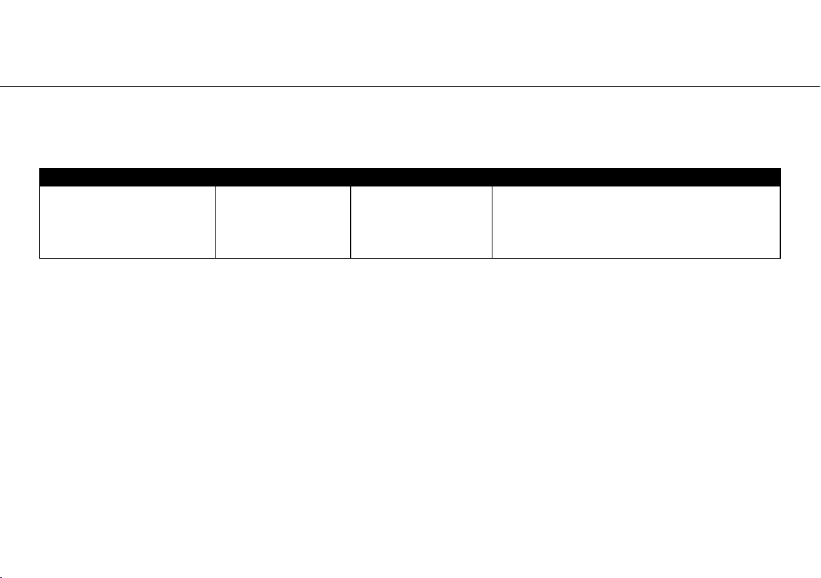
Immunity Test IEC 601-Level Compliance Level Electromagnetic Environment Guidance
Variations of power frequency
and voltage according to
IEC 601-1, Clause 10.2.2. a
(AR-300/600 only)
Nominal frequency up to
100 Hz: variation of ± 1
Hz of nominal frequency;
Variation of ± 10 % of
nominal voltage
Nominal frequency up to
100 Hz: variation of ± 1
Hz of nominal frequency;
Variation of ± 10 % of
nominal voltage
Mains power quality should be that of a typical
commercial and/or hospital environment
12
Electromagnetic compatibility (EMC)
Manufacturer’s declaration – Recommended Separation Distances between portable and mobile
HF- communications equipment and the product (Table 206, EN 60601-1-2)
The product is intended for use in an electromagnetic environment in which radiated RF disturbances are controlled. The
customer or the user of the product can help prevent electromagnetic interference by maintaining a minimum distance
between portable and mobile RF communications equipment (transmitters) and the product – according on output power
and frequency of the communications equipment – as recommended in the following table.
Rated maximum output power
of transmitter in watts (W)
0,01 0,12 0,12 0,23
0,1 0,38 0,38 0,73
1 1,2 1,2 2,3
10 3,8 3,8 7,3
100 12 12 23
For transmitters rated at a maximum output power not listed above, the recommended separation distance d in meters (m) can be estimated using
the equation applicable to the frequency of the transmitter, where P is he maximum output power rating of the transmitter in watts (W) according to
the transmitter manufacturer.
Note 1: At 80 MHz and 800MHz, the higher frequency range applies.
Note 2: These guidelines may not apply in all situations. Electromagnetic propagation is affected by absorption and reflection from structures,
objects, people and animals.
Separation distance according to the frequency of transmitter in meter (m)
150 kHz to 80 MHz
d=1.2√P
80 MHz to 800 MHz
d=1.2√P
800 MHz to 2.5 GHz
d=2.3√P
HF communication equipment
Do not use any portable and mobile HF communication equipment (e.g. mobile telephones) during operation.
These may affect medical electrical equipment.
13
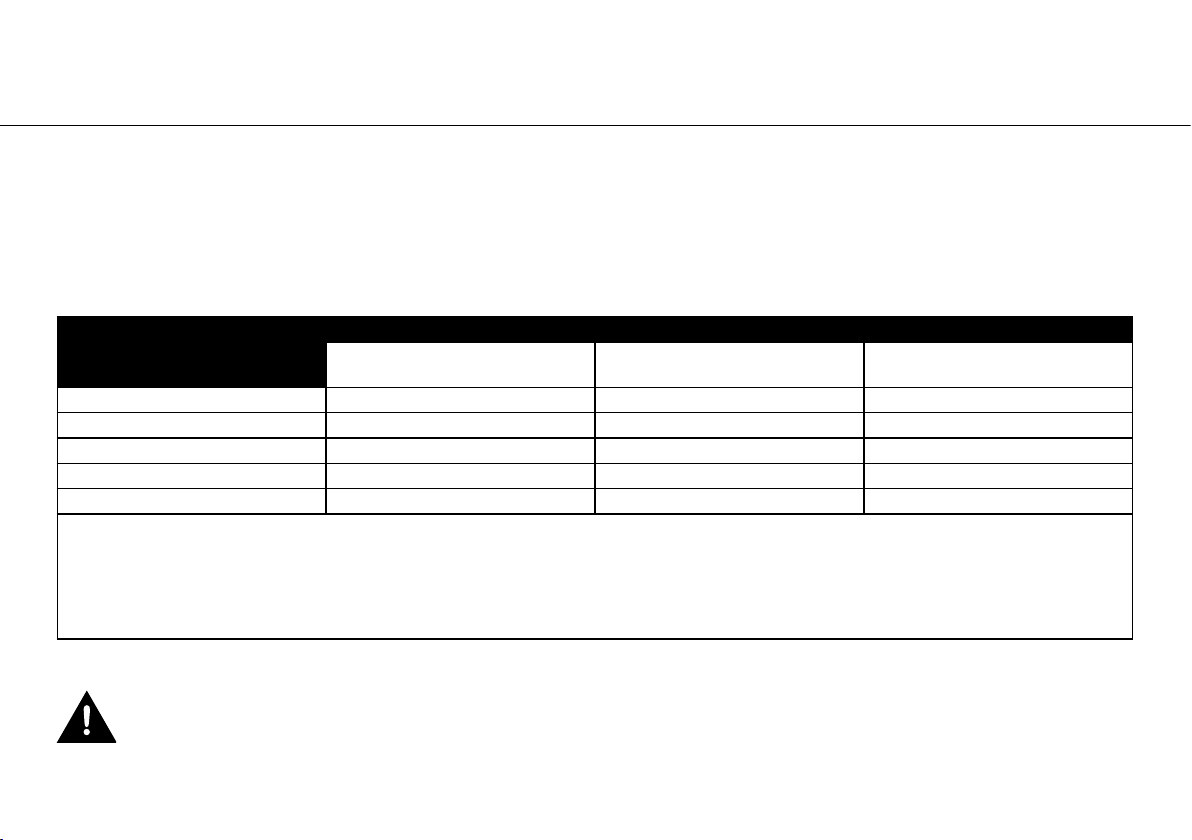
3. System overview
14
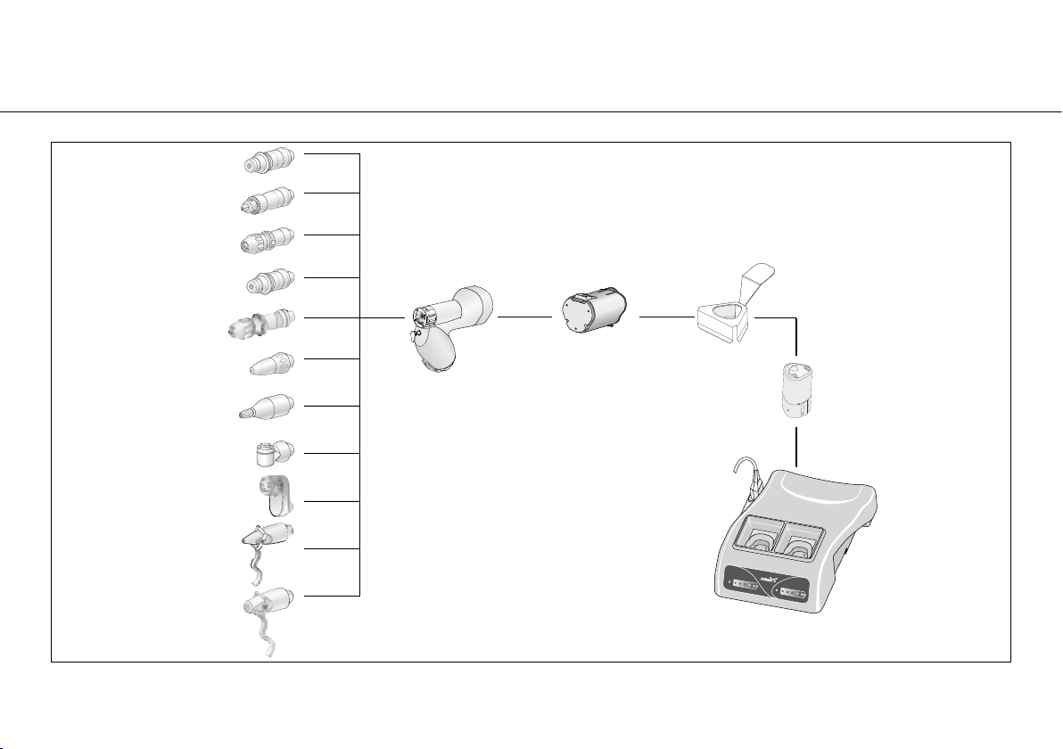
4. System components CE certification according to notified body displayed on packaging
AR-300
Arthrex 300 Handpiece
AR-300L
Battery Pack, Unsterile,
Li-Ion for AR-300
AR-300LBH
Battery Housing
AR-300ATK
Aseptic Transfer Kit
for AR-300
AR-300 / 600
Charging Station
AR-300 / AR-600 Batteries
• Incl. flex (Europa)
• Incl. flex (USA, CAN, J)
• optional flex (UK, IRL)
• optional flex (AUS, NZ)
• optional flex (CH)
• Incl. flex (BR)
15
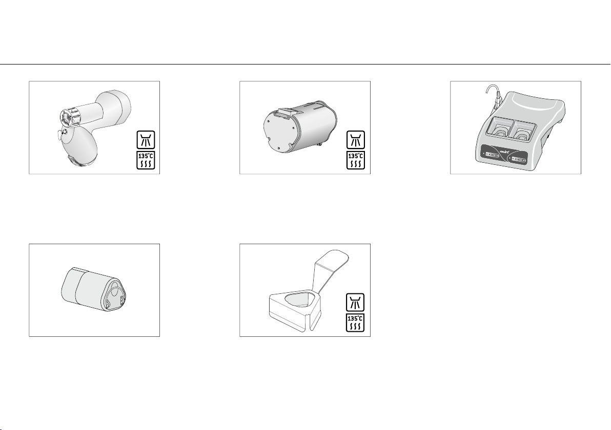
System components CE certification according to notified body displayed on packaging
Saw Attachment -
Sagittal
Drill Attachment -
Style AO
Drill Jacobs Chuck
0-4.0 mm
16
AR-300SAG
Technical data:
Speed/frequency
0-15,000 cpm
AR-300DAO-1
Technical data:
Speed / frequency
0-2,750 rpm
AR-300DJ
Technical data:
Speed / frequency
0-1,300 rpm
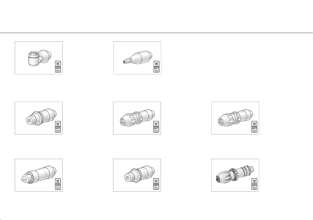
Saw Attachment -
Reciprocating
Drill Keyless Chuck
0-3.0 mm
Drill Attachment -
Style AO
AR-300SR
Technical data:
Speed / frequency
0-15,000 cpm
Travel 2.5 mm
AR-300DK30
Technical data:
Speed / frequency
0-2,750 rpm
AR-300DAO-2
Technical data:
Speed / frequency
0-1,300 rpm
AR-300DK45
Technical data:
Speed / frequency
0-2,750 rpm
Drill Keyless Chuck
2.0-4.5 mm
AR-300DJH
Technical data:
Speed / frequency
0-1,300 rpm
Drill Jacobs Chuck
Hybrid 0-5.0 mm
 Loading...