

Page 1
950-0078-00, Rev. A English
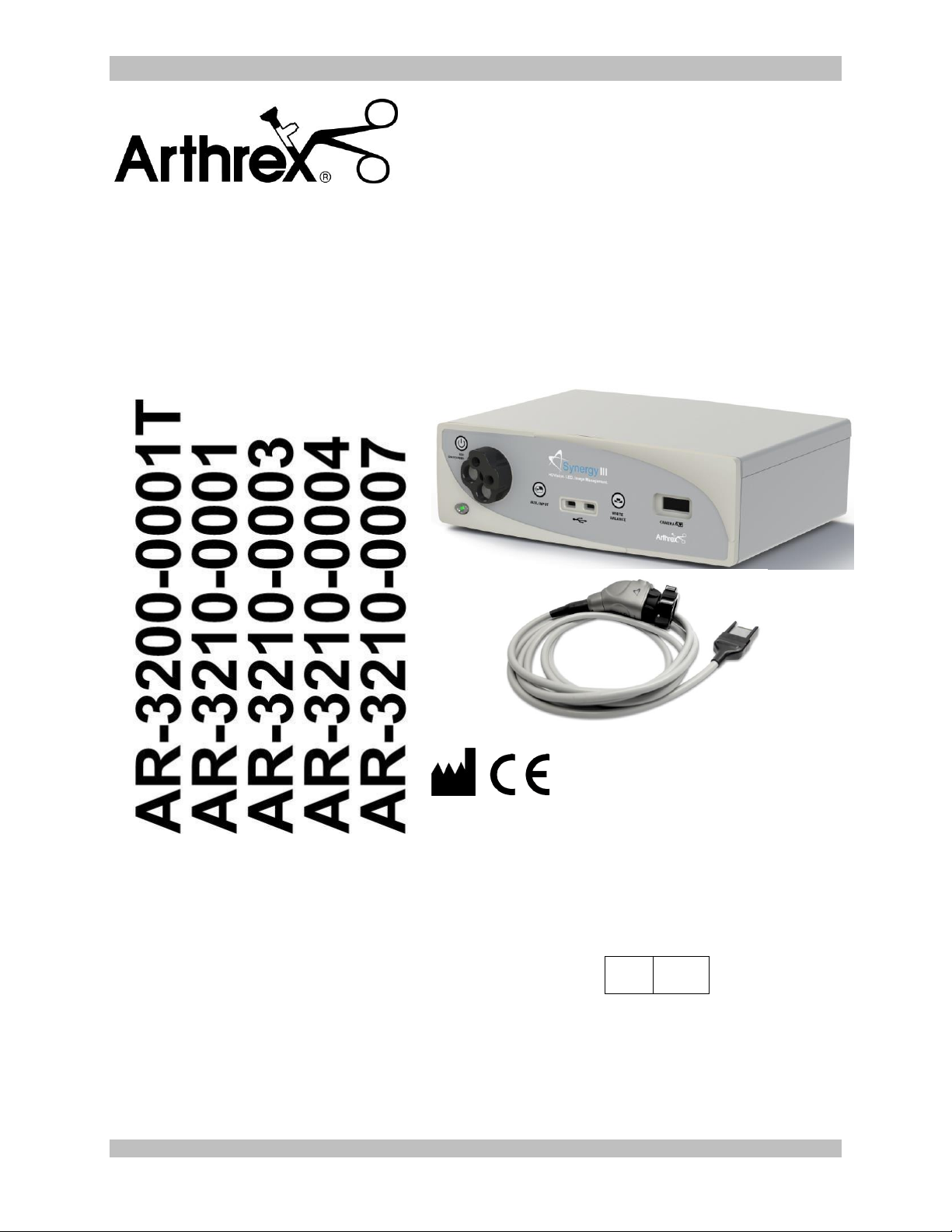
Synergy
HD3
System
Service Manual
The Arthrex Synergy
HD3
System Camera Controller and
Camera Head User’s Guide provides important information
for the safe operation of all components of the Synergy
HD3
Camera System, including accessories. Read this User’s
Guide thoroughly prior to using this system and keep it in
an easily accessible place for use by all operating
personnel. Read and follow all safety warnings, cautions
and precautions.
Arthrex, Inc.
1370 Creekside Blvd.
Naples, FL 34108, USA
+1 (800) 934-4404
Technical Support
1-888-420-9393
EC
REP
Arthrex GmbH
Erwin-Hielscher-Strasse 9
81249 München, Germany
+49 89 909005-0
950-0078-00 A 1 of 69
Page 2

950-0078-00, Rev. A English
This is not a warranty document. For all warranty information, including disclaimers, exclusions,
terms, conditions and related provisions, refer to the “Arthrex U.S. Product Warranty” section of
the Arthrex, Inc. website, found at www.arthrex.com whose provisions are incorporated herein by
reference.
950-0078-00 A 2 of 69
Page 3

950-0078-00, Rev. A English
Table of Contents
3.0 Introduction ................................................................................................................................................ 4
3.1 Intended Use ............................................................................................................... 4
3.2 Contraindications ......................................................................................................... 4
3.3 Warnings and Precautions ........................................................................................... 4
3.4 Symbol Definitions ....................................................................................................... 9
3.5 End of Life, Environmental Directives..........................................................................11
3.6 Initial Use of the Device ..............................................................................................11
3.7 Unpacking and Inspecting the Device .........................................................................12
3.8 Returning the Device ..................................................................................................13
3.9 System Indicators .......................................................................................................14
4.0 System Installation and Operation with Data Input Device ...................................................................... 18
4.1 Installation ..................................................................................................................18
4.2 Accessories for Intended Use .....................................................................................19
4.3 System Setup Facility and Surgeon Settings...............................................................20
4.4 Scheduling and Starting Cases ...................................................................................29
4.5 System Operation without Tablet Data Input Device ...................................................35
4.6 Picture in Picture Operation ........................................................................................37
5.0 Theory of Operation ................................................................................................................................. 39
6.0 Maintenance ............................................................................................................................................. 48
6.1 Life Expectancy ..........................................................................................................48
6.2 Periodic Maintenance .................................................................................................48
6.3 Cleaning and Sterilizing ..............................................................................................48
6.4 Troubleshooting ................................................................ ..........................................51
6.5 Recommended Annual Camera Control Unit Maintenance Requirements ..................53
8.0 Troubleshooting (Tests) ........................................................................................................................... 54
9.0 Technical Information ............................................................................................................................... 59
10.0 APPENDIX [Detailed EMC Information] ................................................................................................... 62
11.0 APPENDIX [SW Version access] ............................................................................................................. 67
950-0078-00 A 3 of 69
Page 4
950-0078-00, Rev. A English
WARNING: The safety and/or health of
the patient, user, or a third party is at
risk. Comply with this warning to avoid
injury to the patient, user, or third party.
PRECAUTION: This contains
information concerning the intended
use of the device or accessory.
Damage to the equipment is possible if
these instructions are not followed.
1.0 Introduction
It is recommended that personnel study this
manual before attempting to operate, clean,
and/or sterilize the Arthrex Synergy
System and accessories. The safe and
effective use of this equipment requires the
understanding of and compliance with all
warnings, precautionary notices, and
instructions marked on the product, and
included in this manual.
The Arthrex Synergy
of:
AR-3200 Console with Wolf Light
Guide Port.
AR-3210-0001 Camera Head with
Integrated Optics
AR-3210-0003 Camera Head, C-
Mount.
AR-3210-0004 Camera Head, C-
Mount 20 foot.
AR-3210-0007 Camera Head, C-
Mount, Zero Degree
NOTE: the AR-3200T Synergy
identical to the AR-3200 except that it
incorporates a Turret Light Guide Adapter
which accepts various light guides.
HD3
System is comprised
1.1 Intended Use
This system is designed for use by
physicians and surgeons and is intended for
endoscopic camera use in a variety of
endoscopic surgical procedures, including
but not limited to, orthopedic, laparoscopic,
urologic, sinuscopic and plastic surgical
procedures. It is also intended to be used as
an accessory for microscopic surgery.
1.2 Contraindications
Do not use the device if endoscopic surgery
is contraindicated.
Do not use the device if the environmental
conditions for use do not meet the standards
or regulations defined in the accompanying
documents.
HD3
HD3
Console is
1.3 Warnings and Precautions
The words WARNING, PRECAUTION, and
NOTE carry special meanings and they should
be read carefully.
NOTE: A note is added to provide additional,
focused, information.
1.3.1 WARNINGS
This equipment is designed for use
by medical professionals completely
familiar with the required techniques
and instructions for use of the
equipment. Prior to using the device,
read and follow all warning and
precautionary notices and
instructions marked on the product
and included in this manual. Become
familiar with the operation and
function of this device and
associated accessories. Failure to
follow these instructions can lead to:
Life-threatening injuries to the patient
Severe injuries to the surgical team,
nursing or service personnel, or
Damage or malfunction of the device
or accessories.
1. Do not open or attempt to service
this system, as this may void your
warranty. There are no userserviceable parts inside.
Removing the cover may
introduce an electric shock
hazard by exposing you to dangerous
high voltages or other risks. If the
system malfunctions, return it for service
immediately.
950-0078-00 A 4 of 69
Page 5
950-0078-00, Rev. A English
2. For the protection of the patient it is
recommended that a back-up camera system
for the Arthrex Synergy
HD3
video system be
maintained, sterilized, and ready to be
implemented.
3. For the protection of the patient it is essential
that the endoscopic video system
interconnection is complete and produces a
viable color picture on the surgical monitor
PRIOR to administration of patient
anesthesia.
4. Disconnect camera head from patient prior to
applying cardiac defibrillation to patient.
5. Only the physician can evaluate the clinical
factors involved with each patient and
determine if the use of this device is
indicated. The physician must determine the
specific technique and procedure that will
accomplish the desired clinical effect.
6. This device and its accessories are to be
used only by physicians and medical
assistants under the direction of a physician
with appropriate technical qualifications.
7. This device shall only be used with original
and manufacturer’s accessories and
replacement parts. Use of other parts or
materials may degrade safety.
8. Do not use in the presence of
flammable anesthetics, gases,
disinfecting agents, cleaning
solutions, or any material susceptible to
ignition due to electrical sparking.
9. Equipment grounding is vital for safe
operation. Plug the power cord into a properly
earthed mains supply outlet whose voltage
and frequency characteristics are compatible
with those listed on the unit or in this manual.
Do not use plug adapters or extension cords;
such devices defeat the safety ground and
could cause injury.
10. This equipment should not share an electrical
outlet or grounding with life supporting or life
sustaining equipment.
11. If one or more mains powered units are
connected simultaneously to one socket by
the means of a distribution box, the sum of
the individual leakage currents may exceed
the tolerated limits.
12. The scope light guide tip can get extremely
hot as result of high intensity light, giving
rise to high temperatures in front of the light
emission window which may cause severe
burns. Always keep the light source in the
STANDBY mode when not in use.
13. Before each use, the outer surface of the
portions of the Endoscope and any
Endoscopically Used Accessory, which are
intended to be inserted into the patient, should
be checked to ensure there are no unintended
rough edges, sharp edges or protrusions which
may cause a safety hazard.
14. Safety hazards to patients may result from
gas embolism caused by, for example, overinsufflation of air or inert gas prior to high
frequency surgery or laser assist gas
15. The leakage current through the patient
could increase using endoscopes with
powered accessories.
16. When Endoscopes are used with Energized
Endoscopically Used Accessories, the
Patient Leakage Currents may be additive.
This is particularly true if a CF Applied Part
is used, in which case a Type CF
Endoscopically Used Accessory should be
used to minimize total Patient Leakage
Current.
17. Explosive gas concentrations inside the
patient can cause hazards while using HighFrequency Endoscopically Used
Accessories.
18. For the protection of service personnel, and
for safety during transportation, all devices
and accessories that are returned for repair
must be prepared for shipment as described
in “Returning the Device” of this manual.
The manufacturer has the right to refuse to
carry out repairs if the product is
contaminated.
19. This equipment/system is intended for use
by healthcare professionals only. This
equipment/system may cause radio
interference or may disrupt the operation of
nearby equipment. It may be necessary to
take mitigation measures, such as reorienting or relocating the Synergy
HD3
Video
System or shielding the location.
20. NOT for use in an Oxygen Rich Environment.
21. Applied Parts of other ME Equipment used
within the configuration for Endoscopic
950-0078-00 A 5 of 69
Page 6
950-0078-00, Rev. A English
Application shall be type BF or CF Applied
Parts.
22. NO Modifications of this equipment is
allowed.
23. Connecting any equipment that has not been
supplied as part of this ME System to Multiple
Socket Outlets may result in increased
leakage currents. Use an IEC Approved
Isolation Transformer to isolate any such
interconnections from the ME System.
24. Before each use or after changing viewing
modes/settings the Operator should check to
ensure that the view observed through the
Endoscope provides a live image (rather than
a stored one) and has the correct image
orientation.
25. Risk of burns!
Light sources emit large amounts of light
energy and thermal energy. As a result:
Surface temperatures of the insertion
portion of the endoscope as well as light
guide connectors on the CCU and the
endoscope rise during use. This can
cause the temperature of the body
tissue to rise to 106 °F (41°C).
Potential Thermal injury to the patient’s
tissue (e.g. from prolonged exposure to
the intense illumination in small cavities,
or if the endoscope’s distal end is
placed in close proximity with the tissue)
may result, as well as burns to the
patient’s or user’s skin. Burns or thermal
damage to surgical equipment may also
result.
Avoid prolonged exposure to intense
illumination.
Use the minimum level of illumination
necessary to satisfactorily illuminate the
target area.
Do not place the endoscope’s distal end
or light guide connector on the patient’s
skin, on flammable materials or on heat
sensitive materials.
Turn the light source off when detaching
the endoscope from the light guide
cable.
Allow the endoscope and light guide
cable to cool down after use.
26. High Frequency [HF] electrical surgical
instruments may lead to severe patient
injuries and/or damage to the endoscope.
Please take caution to insure that the working
element is kept within field of view to prevent
accidental burns. A sufficient distance from
the tip of the endoscope to other conductive
accessories and instruments should be
maintained (10 mm) before activating the HF
output to prevent burns and damage to the
endoscope. Refer to the HF Surgical Device
Instructions for proper and safe use.
27. HF surgical Instruments may interfere with
video images. To prevent such interference,
HF equipment and video imaging equipment
should be connected to different power
supply circuits.
28. Use of Lasers in surgery may result in Eye
Damage or damage to the endoscope from
reflected laser energy. Refer to the Laser
Device Instructions for proper and safe use.
When using a laser always wear
protective glasses designed for the
laser’s wavelength.
Cover the patient’s eyes, or use
protective glasses designed for the
laser’s wavelength.
To prevent damage to the
Endoscope, the Laser should be
activated only after the tip of the laser
can be seen thought the endoscope.
1.3.2 PRECAUTIONS
1. United States Federal law restricts sale of
this device to or on the order of a physician.
2. Do not use the camera with incompatible
equipment or accessories that are not
authorized by Arthrex. Doing so may void
certifications and/or warranties.
3. The warranty becomes void and the
manufacturer is not liable for direct or
resulting damage if:
The device or the accessories are
improperly used, prepared or
maintained;
The instructions in the manual are not
adhered to;
950-0078-00 A 6 of 69
Page 7

950-0078-00, Rev. A English
Non-authorized persons perform
repairs, adjustments or alterations to the
device
Non-authorized persons open the
device.
NOTE: Receipt of technical documentation
from the manufacturer does not authorize
individuals to perform repairs, adjustments,
or alterations to the device or accessories.
Only authorized service personnel may
perform repairs, adjustments or alterations
on the device and accessories. Any violation
will void the manufacturer’s warranty.
Authorized service technicians are trained
and certified only by the manufacturer. The
Manufacturer will make available on request
circuit diagrams, component part lists,
descriptions, calibration instructions and
other information required for service to any
Arthrex Authorized Service Center.
4. This device should only be used in
compliance with its intended use.
5. Prior to each use, the CCU and all
associated equipment must be inspected for
proper operation. Visually inspect lenses to
assure there are no scratches, chips or
cracks.
6. To carry out safe operation, it is absolutely
necessary to carry out proper care and
maintenance of the device and accessories.
See “Maintenance” section of this manual.
7. Ensure that the available mains voltage
matches the mains voltage data on the rear
of the device which is located near the
appliance inlet module.
8. This device may only be connected to
endoscopes which, in their intended use and
technical specifications, are appropriate for
use with the device for the intended medical
procedure. The endoscopes must comply
with the latest version of DIN EN 60601-2-18
and ISO 8600.
9. This equipment has been tested and found
to comply with Class A limits of EN 60601-12:2002. These limits are designed to provide
reasonable protection against harmful
interference in a typical medical installation.
However, if interference does occur with
other equipment, it may be corrected by one
or more of the following measures;
Reorient or relocate this
equipment, the other
equipment, or both;
Increase the distance between
the different pieces of
equipment;
Consult a biomedical engineer.
10. Do not expose the Camera Control Unit
[CCU] to moisture, or operate it in a wet
area, or store liquids above the CCU.
11. Do not excessively bend or kink instrument
power cord or camera head cable.
12. Handle all equipment carefully. If the CCU or
camera head is dropped or damaged in any
way, return it immediately for service.
13. If the camera head or camera head cable
are damaged in any way, or cable or
connector jacket are cut, do not autoclave
camera head, or immerse camera head in
liquid (water, chemical disinfectants or
sterilants, etc.). Notify your Arthrex Sales
Representative. If it is necessary to return
the camera head to Arthrex for service,
disinfect the camera head before shipping
and reference “Returning the Device”.
14. Store camera head and all accessories in a
protective container to prevent damage
during storage. Do not store CCU where it
will be exposed to temperatures in excess of
140°F (+ 60°C).
15. Additional equipment connected to medical
electrical equipment must comply with the
respective IEC or ISO standards (e.g. 60950
for data processing equipment).
Furthermore all configurations shall comply
with the requirements for medical electrical
systems (see IEC 60601-1 or clause 16 or
the 3rd edition of IEC 60601-1, respectively).
Anybody connecting additional equipment to
medical electrical equipment configures a
medical system and is therefore responsible
that the system complies with the
requirements for medical electrical systems.
Attention is drawn to the fact that local laws
take priority over the above mentioned
requirements. If in doubt, consult your local
representative, or the technical department.
950-0078-00 A 7 of 69
Page 8

950-0078-00, Rev. A English
16. Any person who connects external
equipment to signal input and signal output
ports or other connectors has formed a
system and is therefore responsible for the
system to comply with the requirements of
IEC 60601-1-1. If in doubt, contact a
qualified Biomedical technician or your local
representative.
17. This equipment has been tested and found
to comply with the Class A limits for medical
devices to the EN 60601-1 and EN60601-12:2002. These limits are designed to provide
reasonable protection against harmful
interference in a typical medical installation.
This equipment generates uses and can
radiate radio frequency energy and, if not
installed and used in accordance with the
instructions, may cause harmful interference
to other device(s) in the vicinity. However,
there is no guarantee that interference will
not occur in a particular installation. If this
equipment does cause harmful interference
to other devices, which can be determined
by turning the equipment off and on, the
user is encouraged to try to correct the
interference by one or more of the following
measures:
(a) Reorient or relocate the receiving
device.
(b) Increase the separation between the
equipment.
(c) Connect the equipment into an outlet on
a circuit different from that to which the
other devices are connected.
(d) Consult the manufacturer or field service
technician for help.
This unit was not evaluated for use with
electrosurgical devices which access the
site via the same endoscope as the light
source and camera. The unit must be reevaluated prior to use with electrosurgical
devices when they will operate through the
same endoscope as the light source and
camera.
18. After each use, thoroughly clean unit and
accessories (See “Cleaning and
Sterilizing”).
NOTES:
1. Observe all national waste management
regulations.
2. Do not dispose of WEEE as unsorted
municipal waste.
950-0078-00 A 8 of 69
Page 9
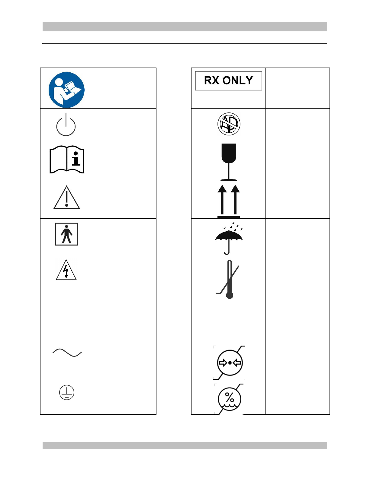
950-0078-00, Rev. A English
Safety Sign
Follow Operating
Instructions
Caution: Federal
Law Restricts this
device to sale by or
on the order of a
Physician.
Power Standby/On
Not for use in the
Presence of
Flammable
Anesthetics.
Attention, Consult
Accompanying
Documents
Fragile
Precaution of
Warning Notice
This Side Up
Type BF Equipment
Keep Dry
Electrical Hazard,
Dangerous
Voltages are
Present. Never
attempt to repair
the equipment.
Only Trained
Service Personnel
may remove the
cover, or obtain
access to system
components.
Temperature Limits
for Storage and
Transport
Alternating Current
Pressure Limits for
Storage and
Transport
Protective Earth
[Ground]
Humidity Limits for
Storage and
Transport
1.4 Symbol Definitions
950-0078-00 A 9 of 69
Page 10
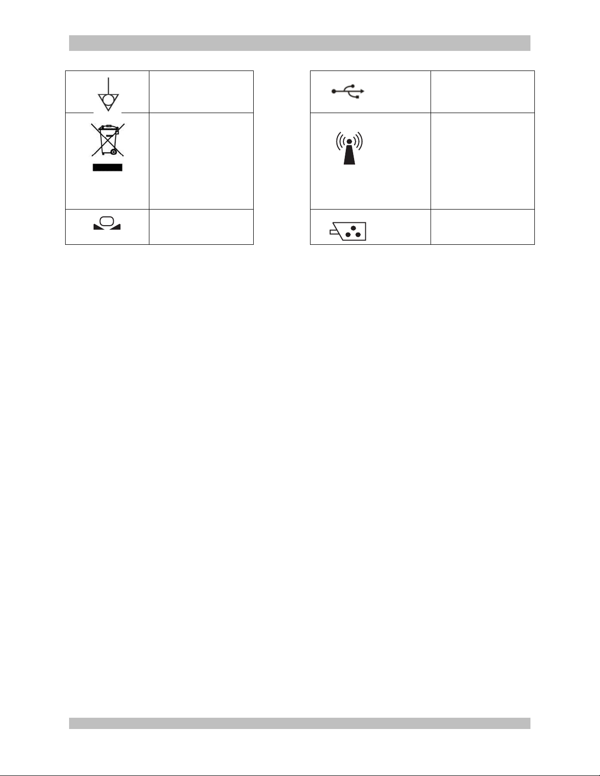
950-0078-00, Rev. A English
Equipotential
[Equipment
Potential]
Universal Serial
Bus
WEEE [Waste
Electronics and
Electrical
Equipment]
Symbol. Regarding
European Union
End-of-Life of
Product.
RF Symbol. Non-
ionizing
Electromagnetic
Radiation
White Balance
Symbol
Color Video
Camera
950-0078-00 A 10 of 69
Page 11
950-0078-00, Rev. A English
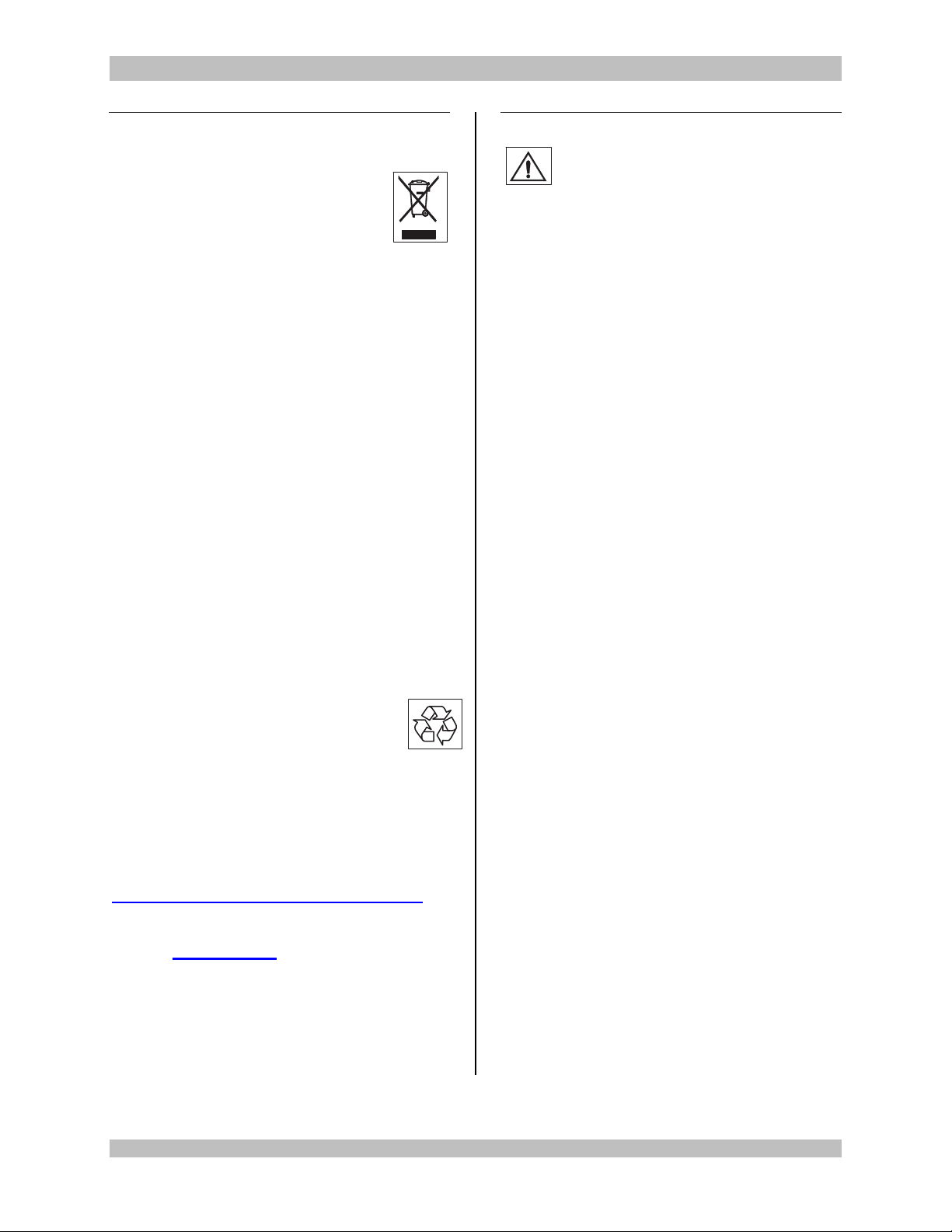
1.5 End of Life, Environmental
Directives
WEEE Directive [2002/96/EC] on
Waste Electrical and Electronic
Equipment
The Directive on Waste Electrical and Electronic
Equipment obliges manufacturers, importers,
and/or distributors of electronic equipment to
provide for recycling of the electronic equipment
at the end of its useful life.
Do not dispose of WEEE in unsorted municipal
waste.
The WEEE symbol on the product or its
packaging indicates that this product must not
be disposed of with other waste. Instead, it is
your responsibility to dispose of your waste
equipment by handing it over to a designated
collection point for the recycling of Waste
Electrical and Electronic Equipment. The
separate collection and recycling of your waste
equipment at the time of disposal will help
conserve natural resources and ensure that it is
recycled in a manner that protects human health
and the environment. For more information
about where you can drop off your medical
endoscopic video equipment at the end of its
useful life for recycling, please contact Arthrex
Customer Service Department.
The Camera Controller contains a
Lithium Coin BATTERY. The BATTERY
must be recycled or disposed of
properly.
NOTE for State of California, USA:
State of California Requirement: Lithium
Batteries contain Perchlorate Material -special
handling may apply. See
www.dtsc.ca.gov/HazardousWaste/Perchlorate
In the US a list of recyclers in your area can be
found at www.eiae.org/
1.6 Initial Use of the Device
WARNINGS:
1. The device is only completely isolated
from the mains if the power plug is
disconnected from the device’s power
inlet module.
2. The electrical installation of the operating
room where the device is used must
comply with applicable national
requirements.
3. Loss of the Mains Voltage may result in
an unacceptable risk due to loss of
Essential Performance. An
Uninterruptable Power Supply [UPS] is
recommended to mitigate this risk.
4. The device is not intended for use in
areas of explosion hazards. If explosive
nitrous gases are used the Camera
Control Unit may not be operated in the
danger zone.
4. Do not simultaneously touch the Camera
Control Unit and the patient. Camera
Control Unit is intended to be used
outside the Patient Vicinity.
6. Additional peripheral equipment
connected as part of the Endoscopic
Video System must meet the
requirements of the following
specifications:
EN 60950 for Information Technology
Equipment.
EN 60601-2-18 for endoscopic
devices.
EN 60601-1 for electro medical
devices.
7. All final Endoscopic Video Systems must
meet the requirements of EN 60601-1-1.
8. Whoever connects additional equipment
to signal input or signal output is
obligated to meet the requirements of the
EN 60601-1-1 standard.
950-0078-00 A 11 of 69
Page 12

950-0078-00, Rev. A English
CAUTION: Do not install the device
in a location near heat sources such
as air ducts or radiators and do not
expose the device to direct sunlight,
excessive dust, or mechanical vibration.
1.7 Unpacking and Inspecting the
Device
Upon receipt, carefully unpack the Synergy
Controller Unit (CCU) and accessories. Ensure
contents are complete and are free from
damage. If any damage is noted contact your
Arthrex Customer Service. Contact the
Manufacturer for Return Authorization PRIOR to
shipping your device for service. Save ALL
packaging materials; they may be needed to
verify any claims of damage by the shipper.
HD3
950-0078-00 A 12 of 69
Page 13

950-0078-00, Rev. A English
1.8 Returning the Device
If it becomes necessary to return the device,
always use the original packaging. The
manufacturer does not take responsibility for
damage that has occurred during transportation
if the damage was caused by inadequate
transport packaging. Please make sure that all
required information has been supplied. Call
Arthrex for a RMA Number for the device return
for service.
Owner’s Name
Owner’s Address
Owner’s Daytime Telephone Number
Device type and model.
Serial Number
Detailed explanation of the damage.
NOTE:
1. The CCU shall be cleaned per
section Cleaning and
Sterilization prior to returning for
service.
2. The Camera Head shall be
cleaned and Sterilized per
Cleaning and Sterilization prior
to returning for service. Camera
Head shall be clearly labeled as
“Sterile.”
Arthrex shall not implement repairs on
equipment which is not returned cleaned and
sterile
950-0078-00 A 13 of 69
Page 14
950-0078-00, Rev. A English
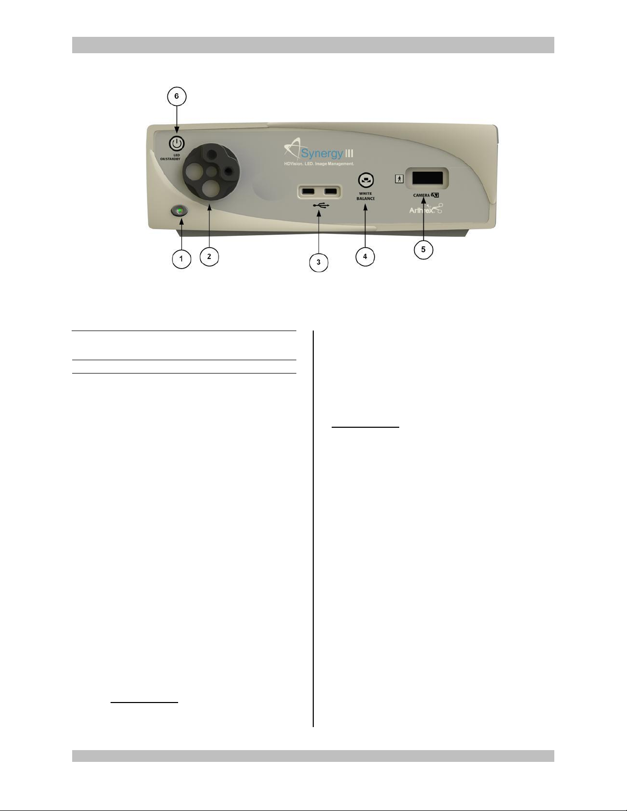
Figure 1- Synergy
HD3
Front Panel [AR-3200-0001T]
1.9 System Indicators
1.9.1 Synergy
1. On/Standby Switch — The On/Standby
switch toggles the (CCU) between ON
[operational mode], and STANDBY. The
Green LED will illuminate when the CCU is
in the ON mode. Press and HOLD the
switch to toggle between ON and
STANDBY.
2. Light Guide Turret [xxx]- Turret for Light
Guide input
3. USB Ports [2x] — Connect USB devices
here.
4. “WHITE BALANCE” Button — Press to
initiate camera white balance.
HD3
Front Panel
5. “CAMERA” Input Connection — Insert
the camera head connector here. The
camera head connector and receptacle are
specially keyed to prevent the camera head
from being improperly connected. Ensure
that the “UP” label on the camera head
connector is facing upwards when the
camera head connector is inserted.
PRECAUTION: Ensure camera head
contacts are clean and dry and cool
15 minutes prior to insertion.
6. Light Source On/Standby Switch — The
Light Source On/Standby Switch toggles
the Light Source between ON [Operational
Mode], and STANDBY.
PRECAUTION:
1. Use Only FUSED Light Guides to ensure
proper operation of LED Engine.
2. LED Engine Cleaning Requirements.
Allow LED Engine to cool for ½ hour
before cleaning.
Dampen one end of a cotton swab with
isopropyl alcohol.
Clean any residue from optic using
circular motion.
Use the DRY END of the cotton swab to
dry the face of the optics.
Inspect the optics for residue or cotton
fibers and clean as required.
Allow to AIR DRY for 5 minutes prior to
use.
950-0078-00 A 14 of 69
Page 15
950-0078-00, Rev. A English
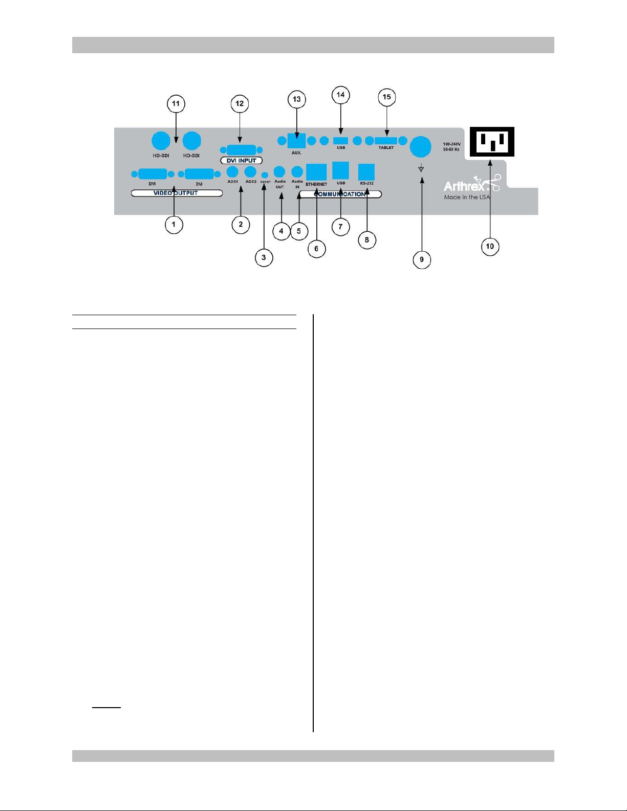
Figure 2- Synergy
HD3
Rear Panel
1.9.2 Rear Panel
1. “DVI” Video Output Connectors —
Supplies a digital video signal output in DVID format.
2. Accessory Ports (Inputs/Outputs - 2X
mini Stereo-Phone Connectors) —
Accessory ports allow for control of the
Camera Control Unit (CCU) with a
footswitch, or for the CCU to control external
devices through the camera head buttons.
3. Reset Button — Resets CCU to factory
Defaults.
4. Audio Out- Line Level audio output to
Medical Grade devices.
the various Medical Electrical [ME]
equipment which make up a Medical
Electrical system, or to reduce differences of
potential which can occur during operation
between the bodies of the Medical Electrical
devices and conductive parts of other
objects. The Potential Equalization
Connector may be connected directly
between any ME Devices, or to a common
busbar of the electrical installation.
Reference IEC 60601-1 for ME Systems.
10. IEC 320 Power Inlet Module (100-240V~,
50/60 Hz) — The CCU is equipped with a
switching power supply that automatically
adjusts to the line voltage being used.
Accepts the supplied hospital grade power
cord.
5. Audio IN-Line Level audio input for
Microphone
6. Ethernet Connector- Isolated-10/100
MB/Sec.
7. USB Connector - Connect USB devices
here.
8. RS-232 Connector-Isolated-connection to
devices requiring Serial Control.
9. Potential Equalization Connector (POAG)
— Potential Equalization Connector per DIN
42801.
NOTE: The purpose of the Potential
Equalization Connector is to equalize the
potentials between different metal parts of
950-0078-00 A 15 of 69
11. HDSDI- 3G Serial Video Output
12. DVI Input – 1080P/60 input from other
medical devices
13. AUX-Ethernet connection
14. USB – USB Connection
15. USB TABLET CONNECTION– Connect
Tablet Data Input device here. Provides for
data interchange and tablet charging.
Page 16
950-0078-00, Rev. A English
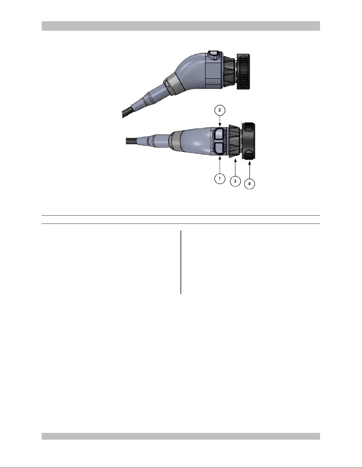
Figure 3-AR-3210-0001 3 CCD Camera Head with Integrated Optics
1.9.3 AR-3210-0001 Camera Head with Integrated Optics
1. Button 1 — A programmable button
that can activate various functions of the
camera. See “Optional Tablet Data Input
Device” for programming information.
2. Button 2 — A programmable button
that can activate various functions of the
camera. See “Optional Tablet Data Input
Device” for programming information.
3. Focus Ring — Used to sharpen, or
bring into focus, the image detail.
4. Grasping Mechanism — Accepts and
locks into place the compatible scope.
DIN 58105 compliant endoscope
interface.
950-0078-00 A 16 of 69
Page 17
950-0078-00, Rev. A English
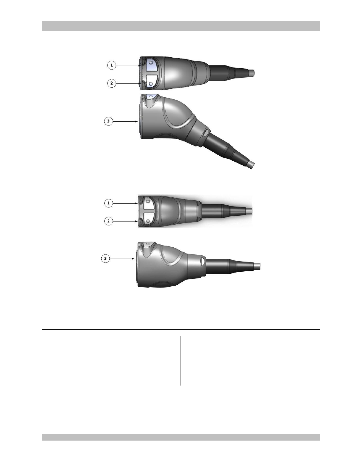
Figure 4-AR-3210-0003 [C-MT], AR-3210-0004 [C-MT, 20 Foot]
Figure 5-AR-3210-0007 [C-MT, Zero Angle]
1.9.4 C-Mount Camera Heads
1. Button 1 — A programmable button
that can activate various functions of the
camera. See “Optional Tablet Data Input
Device” for programming information.
2. Button 2 — A programmable button
that can activate various functions of the
camera. See “Optional Tablet Data Input
Device” for programming information.
3. C-Mount Threads — Accepts standard
C-Mount Optical Couplers.
950-0078-00 A 17 of 69
Page 18

950-0078-00, Rev. A English
2.0 System Installation
and Operation with
Data Input Device
2.1 Installation
NOTE:
1. Your Synergy
indicate which software configuration is
enabled at boot up, on the Video Monitor’s
Splash screen.
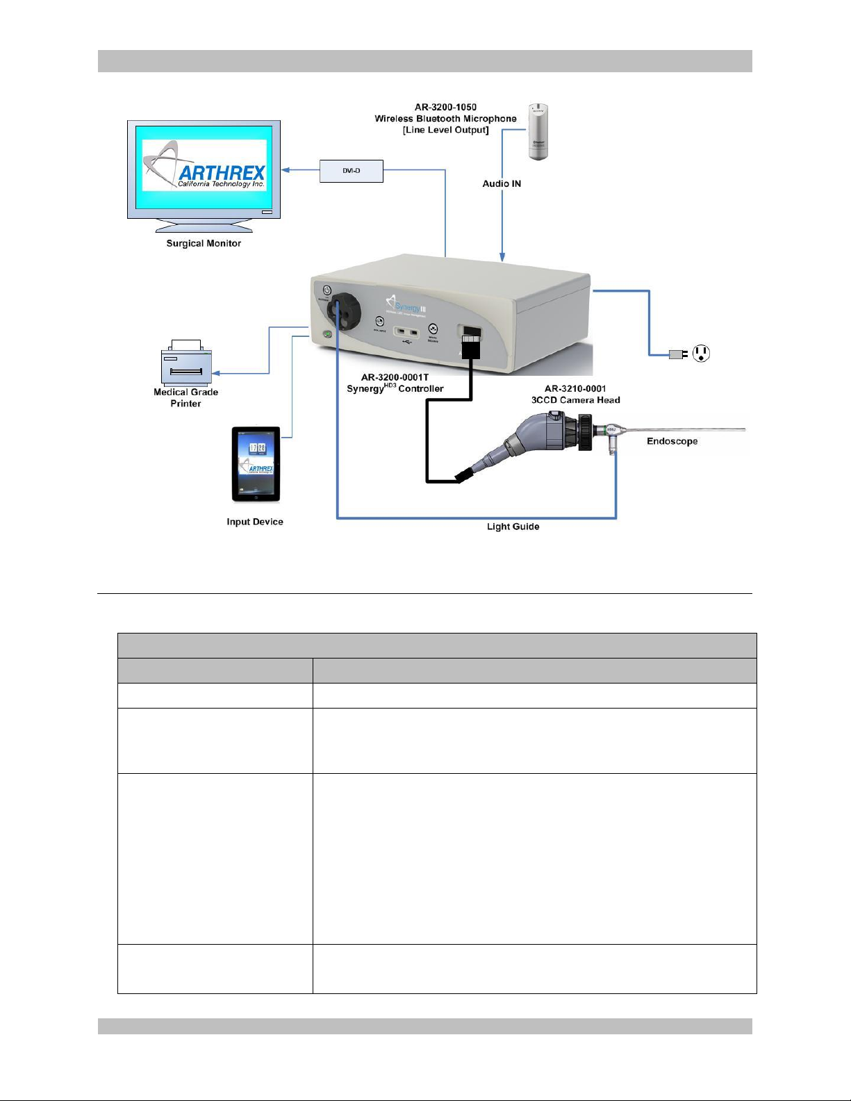
2.1.1 Typical System Installation
NOTE: See “Typical System Interconnect
Diagram, Figure 6
1. Place Synergy
shelf.
2. Attach monitor to the tower and connect
monitor DC power cable to the rear panel of
the monitor as shown.
3. Attach Synergy
secondary tower arm. Connect the cable
from the docking cable to the connector
labeled “tablet” on the back of the
Synergy
4. Connect a DVI cable to the DVI output on
the rear panel of the Synergy
Connect the other end of the DVI cable to
HD3
console.
HD3
Camera Control Unit will
HD3
console (CCU) on tower
HD3
Tablet docking station to
HD3
console.
the DVI input of the display monitor. (An
HD-SDI cable may be used instead of DVI).
5. If using a printer, connect printer cable to
USB connector on the rear panel of the
Synergy
printer cable to the printer.
6. Plug the AC power cord into the Synergy
HD3
console. Connect other end of
HD3
power inlet module and a standard
grounded AC Mains outlet (100-240 V˜, 5060Hz).
7. Insert the card edge connector the
SynergyHD3 camera head into the camera
receptacle on the front of the console.
NOTE: Ensure the camera head connector
contacts are clean and dry prior to
insertion.
8. Connect the Light Guide cable into the Light
Guide receptacle on the front panel of the
Synergy
HD3
console. Attach the other end of
the Light Guide cable to the endoscope.
10. Insert the endoscope into the Synergy
HD3
camera head grasping mechanism.
11. Press the Light Source On/Standby Switch
to activate LED light engine.
NOTE: If there is no Light Guide cable
connected to the Synergy
HD3
console,
pressing the On/Standby Switch will not
activate the LED light engine until one is
connected.
950-0078-00 A 18 of 69
Page 19
950-0078-00, Rev. A English
Figure 6- Synergy
HD3
Typical Interconnect Diagram With OPTIONAL Tablet Data Input Device
Arthrex Synergy
HD3
System Accessories
Part Number
Description
AR-3200-1004
Tablet Computer Data Input Device
SONY UP-PR80MD
SONY UP-PR80MD with
upDR80MD/NKIT
Medical Grade Printers
AR-3250-2601
AR-3250-2602
AR-3250-2603
AR-3250-3201
AR-3250-3203
AR-3250-3204
Medical Grade Surgical Monitor 26”
Medical Grade Surgical Monitor 25”
Medical Grade Surgical Monitor 26”
Medical Grade Surgical Monitor 32”
Medical Grade Surgical Monitor 32”
Medical Grade Surgical Monitor 32”
AR-3240-3527
AR-3240-5027
Light Guide 3.5mm x 274cm
Light Guide 5.0mm x 274cm
2.2 Accessories for Intended Use
950-0078-00 A 19 of 69
Page 20
950-0078-00, Rev. A English
Arthrex Synergy
HD3
System Accessories
Part Number
Description
AR-3240-5040
Light Guide 5.0mm x 400cm
AR-3200-1050
Bluetooth Wireless Microphone
AR-3210-0005
C-Mount Optical Zoom Coupler
AR-3210-1005
Video Input/Output Converter
2.3 System Setup Facility and Surgeon Settings
NOTE: Facility, surgeon, and procedural settings are made from the SynergyHD3’s tablet Data Input
Device.
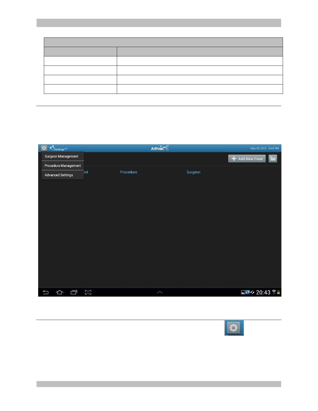
2.3.1 System Set-Up can be accessed by pressing the Maintenance Icon on the
Synergy
950-0078-00 A 20 of 69
Figure 7-System Maintenance
HD3
Tablet Data Input Device and then selecting “Advanced Settings”
Page 21
950-0078-00, Rev. A English
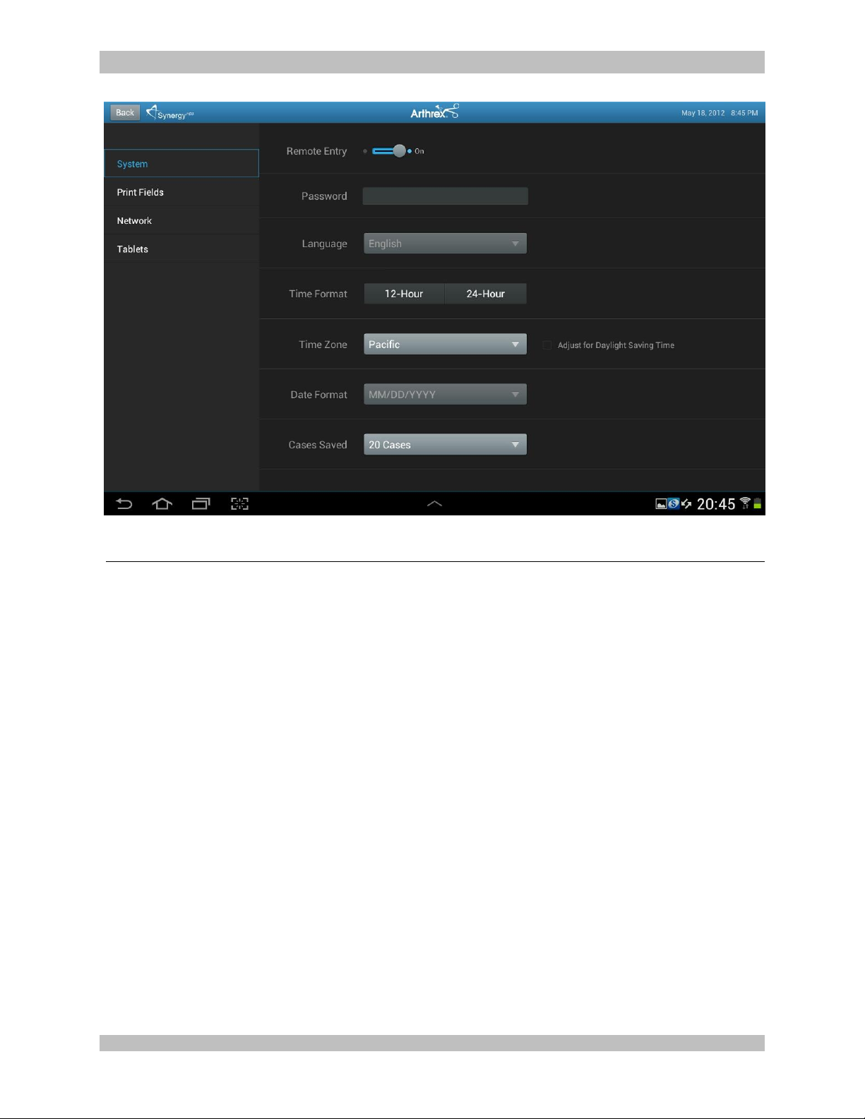
Figure 8-System Maintenance Screen
2.3.2 Selecting “System” button enables several facility preferences to be setup;
“Remote Entry” enables users that have networked the Synergy
patients from a networked computer.
“Password Access” can be set to on or off. On will require a password in order to enter
add patients remotely.
Users can also select “language, time format, Date format, the number of cases saved.
HD3
system to add
950-0078-00 A 21 of 69
Page 22
950-0078-00, Rev. A English
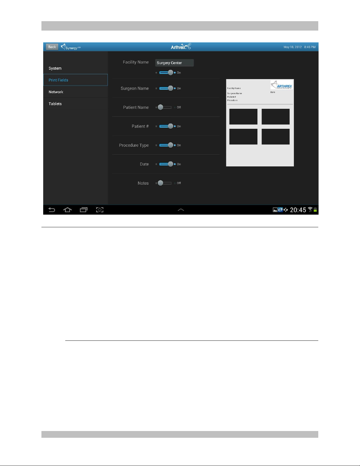
Figure 9-System Maintenance Print Fields
2.3.3 Selecting “Print Fields” allows facilities preferences to be setup for the fields that will be
included on a print. Available Fields are;
Facility Name
Surgeon Name
Patient Name
Patient I.D.#
Procedure Type
Date
Notes
Note: It should be noted that “Print Fields” are also selectable as surgeon preferences,
although any conflict between facility preference and surgeon preference would be reconciled
to facility preference.
950-0078-00 A 22 of 69
Page 23
950-0078-00, Rev. A English
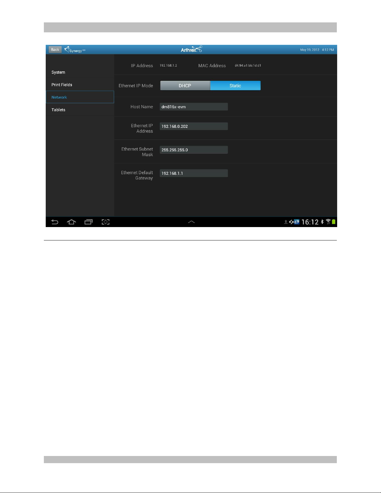
Figure 10-System Maintenance Network
2.3.4 Selecting “Network” allows for connecting the Synergy
are:
Ethernet IP Mode
Host Name
Ethernet IP Address
Ethernet Subnet Mask
Ethernet Default Gateway
HD3
system to a facility network. Fields
950-0078-00 A 23 of 69
Page 24
950-0078-00, Rev. A English
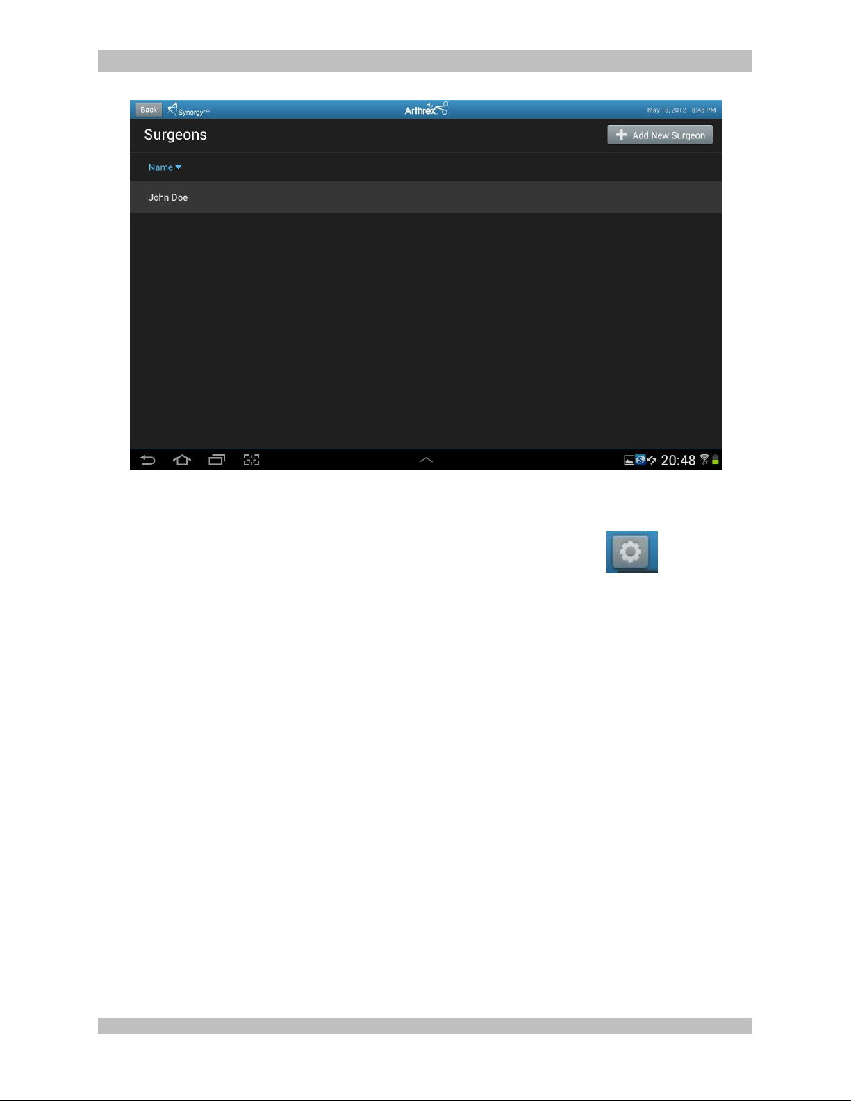
Figure 11-Surgeon Management List
2.3.5 Surgeons can be added to the Synergy
2.3.6 To add surgeons and their preferences, press the maintenance icon on the
Synergy
HD3
Tablet Data Input Device and then select Surgeon Management. A list of
HD3
with their own system preferences.
surgeons will appear.
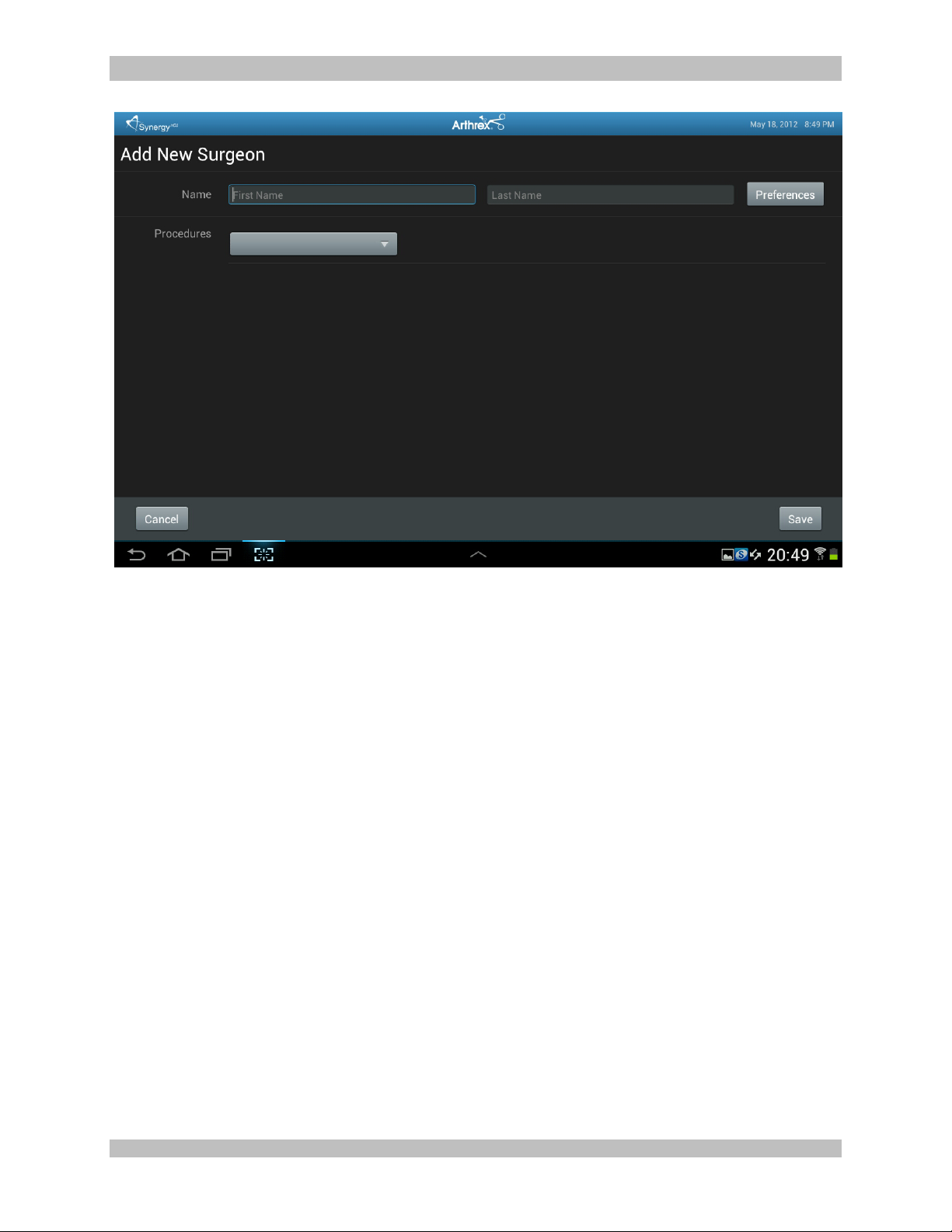
2.3.7 To add a surgeon, press the “+ Add New Surgeon” button, enter the first and last name of a
surgeon, then press the “Preferences” button
950-0078-00 A 24 of 69
Page 25
950-0078-00, Rev. A English
Figure 12-Surgeon Management Preferences
950-0078-00 A 25 of 69
Page 26
950-0078-00, Rev. A English
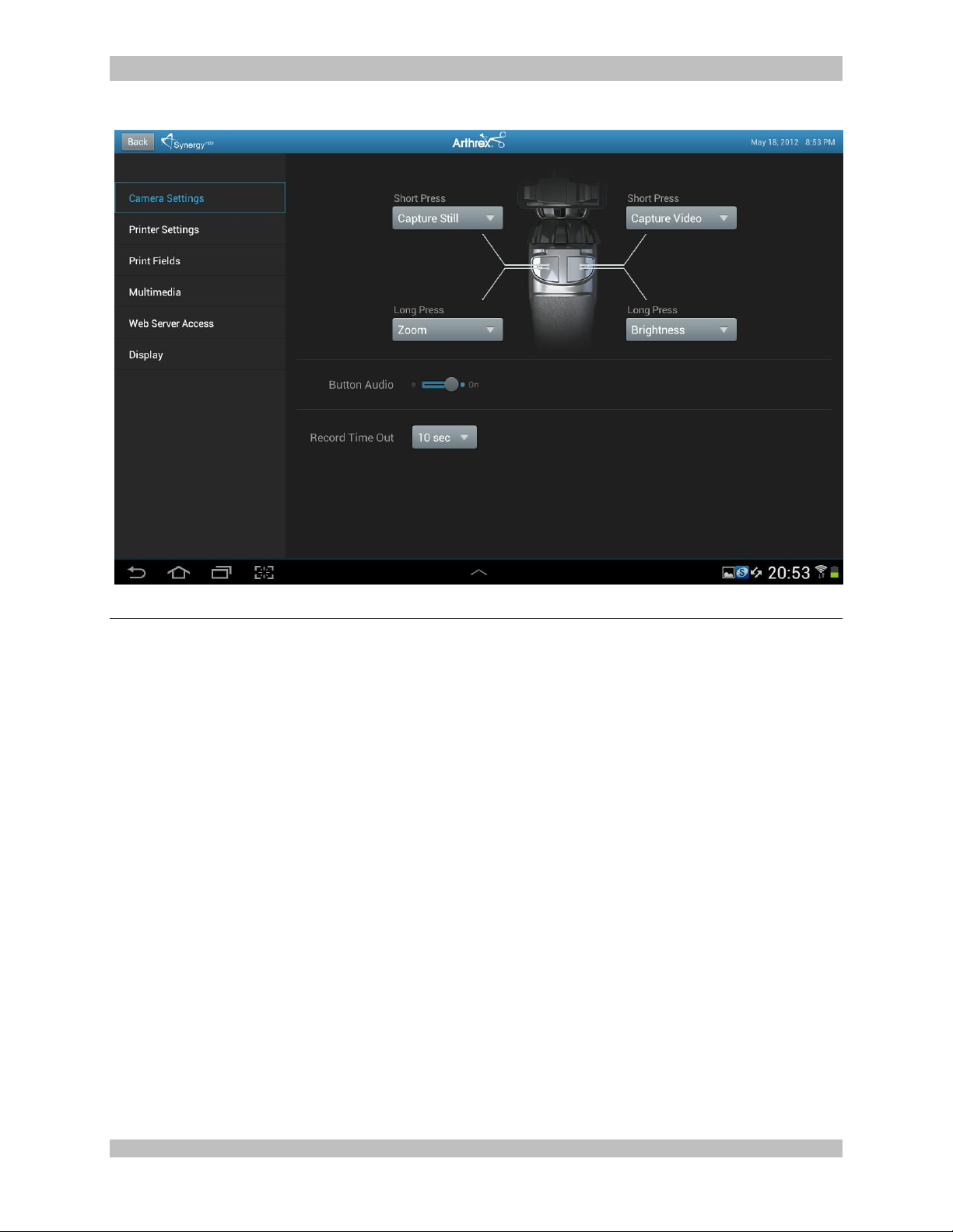
Figure 13-Surgeon Preferences Settings
2.3.8 Surgeon preferences can be defined for the following:
Camera Settings (including
camera head button setup)
Printer Settings
Print Fields
Multimedia
Web Server Access
Display
950-0078-00 A 26 of 69
Page 27
950-0078-00, Rev. A English
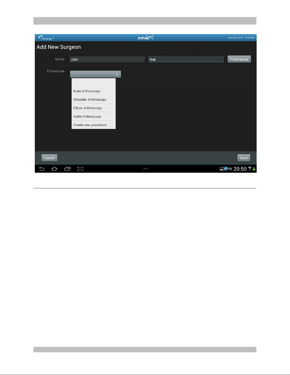
Figure 14-Surgeon Management Procedures Select
2.3.9 Procedure preferences can be added to individual surgeon preferences. On the surgeon
management list, select a surgeon, and a list of procedures will appear
2.3.10 Select the appropriate Procedure for the Surgeon. If the procedure is not currently in the list,
select the “Create New Procedure” from the Procedures drop down list, and enter the name of
the new procedure.
950-0078-00 A 27 of 69
Page 28
950-0078-00, Rev. A English
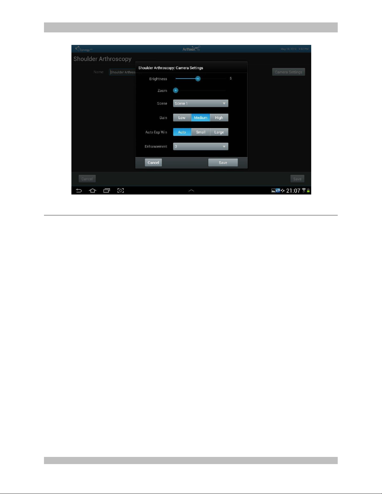
Figure 15-Surgeon Preferences Camera Settings
2.3.11 After entering Procedure Name, select “Camera Settings”. Surgeon preferences may be
entered for:
Brightness
Zoom
Scene
Gain
Auto Exposure Window
Enhancement
NOTE: If a surgeon performs multiple types of procedures and it is necessary to add additional
procedures, press the “Add Procedure” icon.
950-0078-00 A 28 of 69
Page 29
950-0078-00, Rev. A English
2.4 Scheduling and Starting Cases
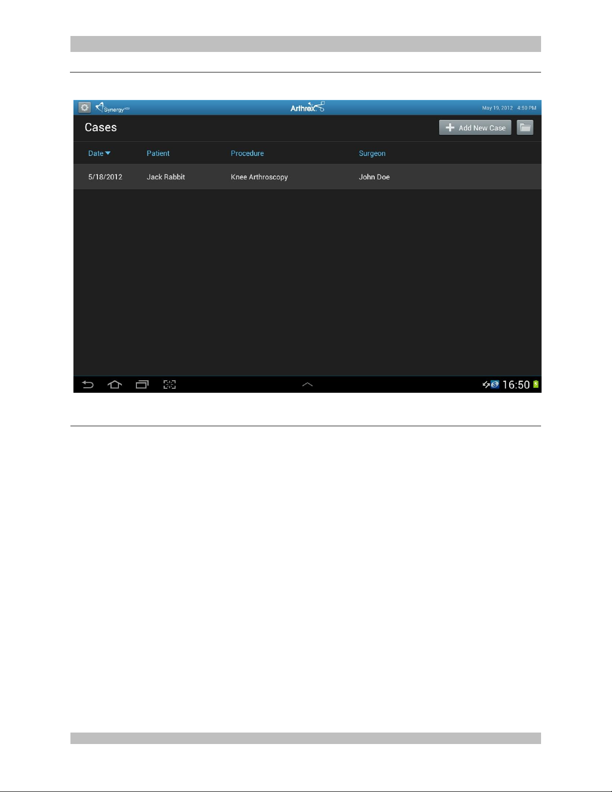
Figure 16-Scheduling a case
2.4.1 To schedule a case, press the “+ Add New Case” icon
950-0078-00 A 29 of 69
Page 30
950-0078-00, Rev. A English
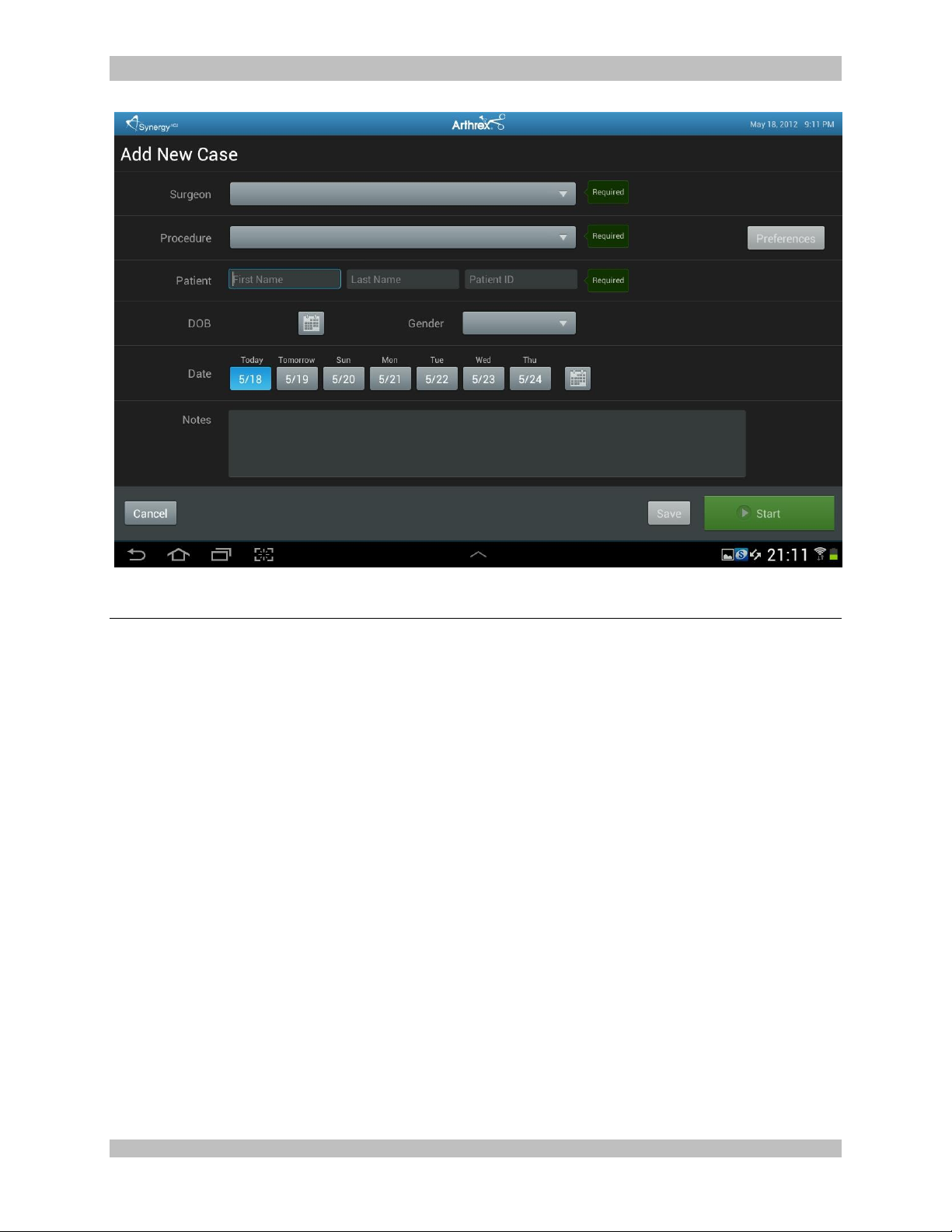
Figure 17-Scheduling a Case
2.4.2 Select the “Surgeon” and/or “Procedure,” and enter data in the following required fields.
Patient First Name
Patient Last Name
Patient I.D. #
2.4.3 Press the “Save” icon
950-0078-00 A 30 of 69
Page 31
950-0078-00, Rev. A English
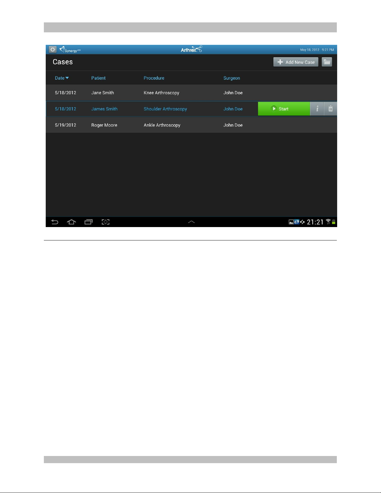
Figure 18-Starting a Case
2.4.4 To start a case, select the case/patient from the Case List and press the “Start” icon
NOTE: Cases may also be started from the “Add Case” screen by entering the required fields
and pressing the “Start” icon.
950-0078-00 A 31 of 69
Page 32
950-0078-00, Rev. A English
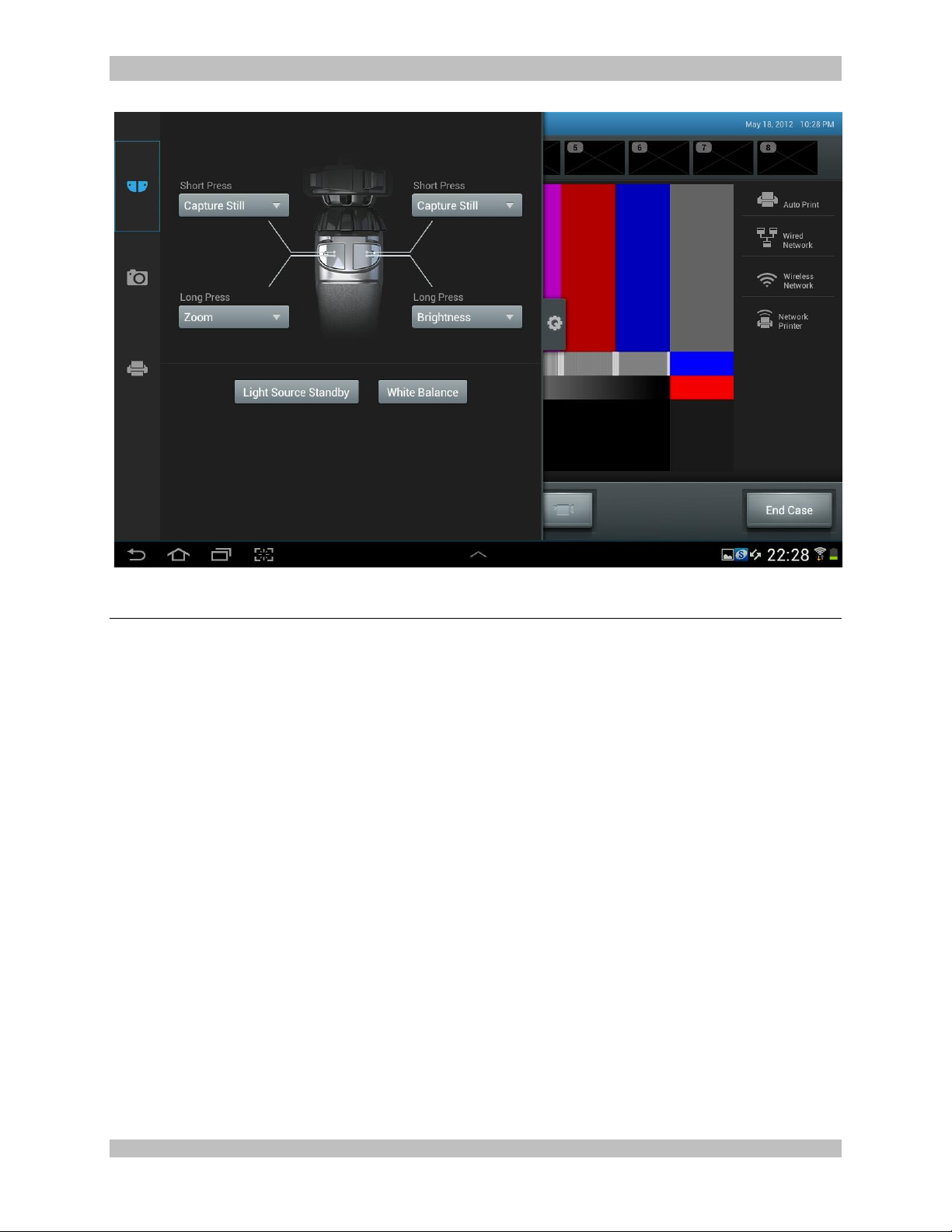
Figure 19-Camera Head Button Change; During Case
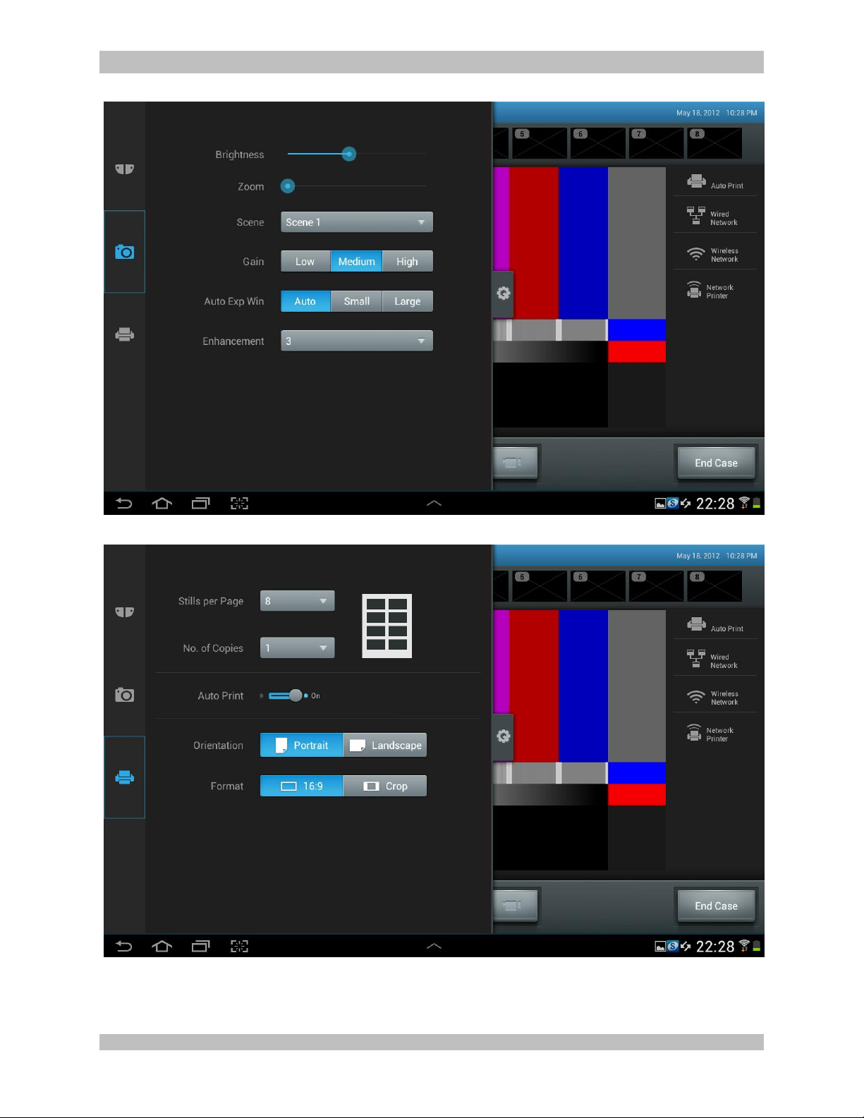
2.4.5 Changes to SETTINGS may be made during the procedure by pressing the “Maintenance
Icon”. Changes may be made to the following:
Camera Head Button Functions
Camera Settings
Print Settings
950-0078-00 A 32 of 69
Page 33
950-0078-00, Rev. A English
Figure 20-Camera Change; During Case
Figure 21-Print Changes; During Case
950-0078-00 A 33 of 69
Page 34
950-0078-00, Rev. A English
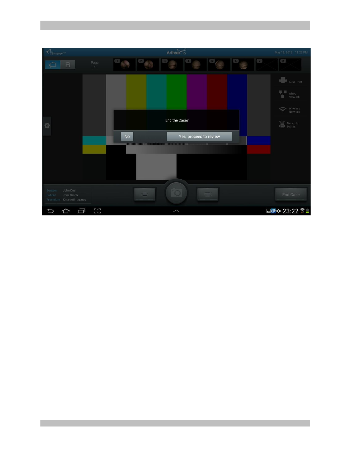
Figure 22-Ending a case
2.4.6 Ending a Case; to end a case, press the “End Case” Icon.
NOTE: An “End Case” confirmation message will appear. If confirmed, the case will end and the
Synergy
HD3
Tablet Data Input Device will transition to the case review screen.
950-0078-00 A 34 of 69
Page 35
950-0078-00, Rev. A English
2.5 System Operation without Tablet
Data Input Device
1. Connect the Synergy
“Typical System Installation”, Figure 6.
HD3
System per
2. The camera will take approximately 3040 seconds to fully load its boot
software. When the software has fully
loaded you will see the Synergy
HD3
Initial
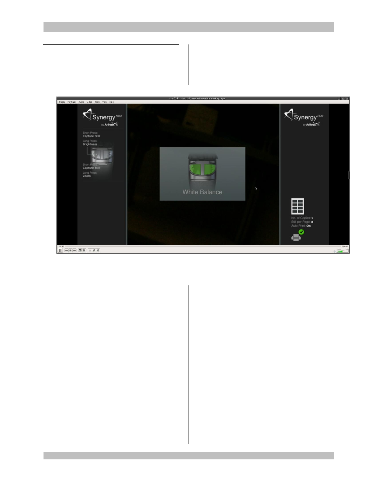
Screen shown below in Figure 23
Figure 23- Synergy
3. The Synergy
HD3
Initial Screen will indicate
the Factory Default settings for the Camera
Head Button programming.
4. Both buttons SHORT presses will capture
Still Images.
5. Long Press on the LEFT BUTTON will
control Brightness.
After a LONG press on the LEFT
BUTTON, pressing the Right Button will
INCREASE Brightness.
After a LONG press on the LEFT
BUTTON, pressing the Left Button will
DECREASE Brightness.
6. Long Press on the RIGHT BUTTON will
control Digital Zoom.
After a LONG PRESS on the RIGHT
BUTTON, pressing the RIGHT Button
will INCREASE ZOOM.
HD3
Initial Screen
After a LONG PRESS on the RIGHT
BUTTON, pressing the LEFT Button will
DECREASE ZOOM.
7. The Synergy
HD3
Initial Screen will also
indicate that the Printer is Active and that it
is set to 8 prints per page.
8. The center screen of the Synergy
HD3
Initial
Screen shows that Both Buttons are now set
to White Balance, and that a White Balance
Operation is required to initialize the
Synergy
HD3
use.
9. Turn on the LED Light Source.
10. Using a stack of 4 x 4 white gauze, hold the
tip of the Endoscope approximately 1 inch
away from the gauze until the gauze image
fills the screen completely.
11. Press either of the Camera Head buttons to
start the White Balance Operation.
950-0078-00 A 35 of 69
Page 36
950-0078-00, Rev. A English
12. The Surgical monitor will display one of the
following.
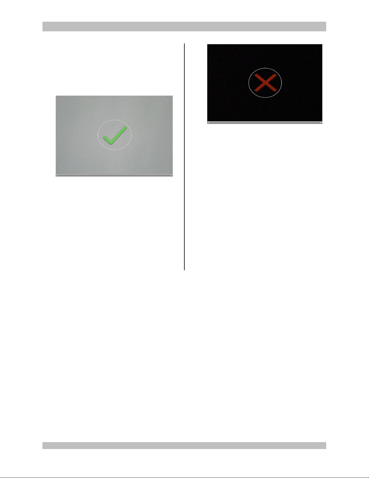
When the White Balance has been
completed successfully, a Green Check
Mark with WHITE BALANCE below will
be shown on screen.
Figure 24-White Balance OK
When the White Balance has not been
completed successfully, a Red X with
WHITE BALANCE below will be shown
on screen.
Figure 25-White Balance Fail
13. If the White Balance Operation has
been successful, the camera will enter
the Surgical Ready Mode and be ready
for surgical operation.
14. If the White Balance Operation has not
been successful, you must move the Tip
of the Endoscope closer or farther from
the White Gauze until the operation can
be completed successfully.
15. Once the White Balance Operation has
been successfully completed, the
Camera Head buttons will function as
defined on the Synergy
HD3
Initial Screen
Figure 23.
950-0078-00 A 36 of 69
Page 37
950-0078-00, Rev. A English
2.6 Picture in Picture Operation
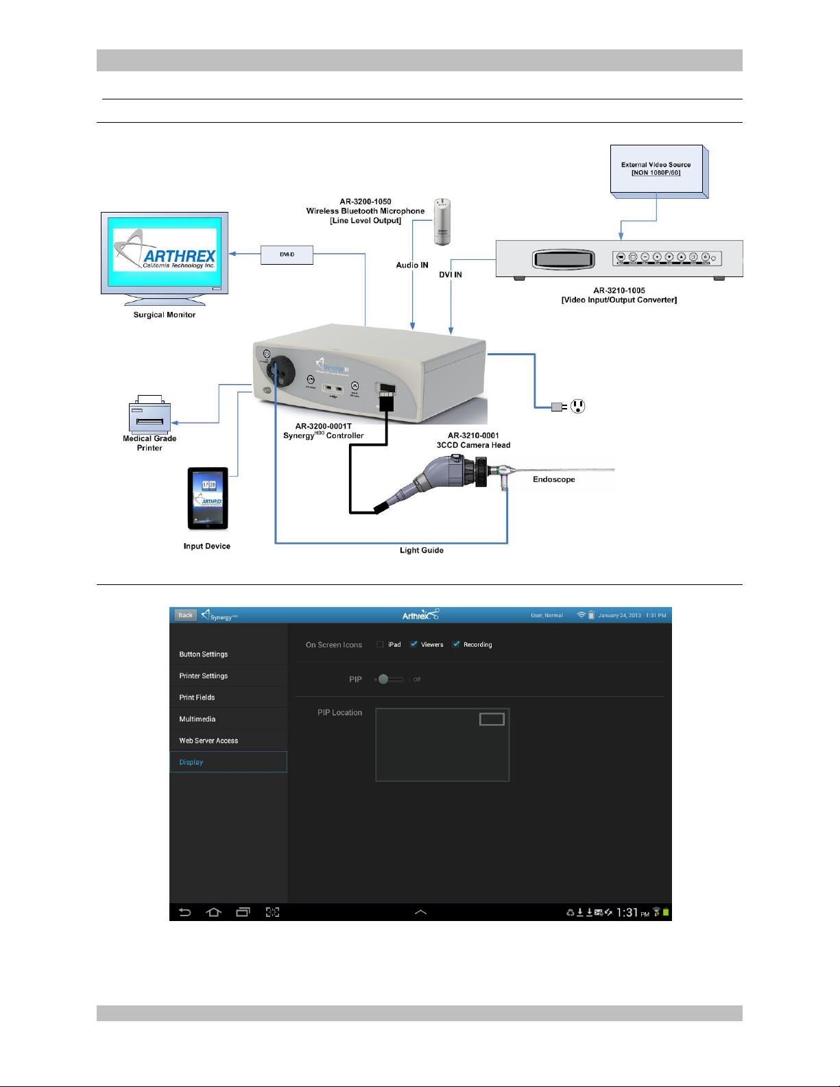
Figure 26-Picture in Picture System Set Up
Figure 27-Tablet PIP Control
950-0078-00 A 37 of 69
Page 38

950-0078-00, Rev. A English
2.6.1 The Synergy HD3 Camera Controller [AR-3200 and AR-3200T] can be used
in the Picture in Picture Mode to display a Picture in Picture [PIP] on the
surgical monitor.
2.6.2 Second video source for PIP is connected to the Camera Controller’s DVI
Input.
2.6.3 The Synergy HD3 Camera Controller [AR-3200 and AR-3200T] will accept
ONLY DVI 1080P/60 video.
2.6.3.1 This can be accomplished by connecting a DVI 1080P/60 VIDEO
SOURCE directly to the Camera Controller’s DVI Input, or by
using the optional AR-3210-1005 Video Input/Output Converter.
2.6.3.2 The AR-3210-1005 Video Input/Output Converter is connected to
the Camera Controller DVI Input, and the NON 1080P/60 video
source is connected to the AR-3210-1005, which will convert the
source to the needed 1080P/60 video format for PIP.
2.6.4 The Tablet Data Input Device is utilized to configure PIP.
2.6.4.1 PIP Enable/Disable
2.6.4.2 PIP Location
2.6.4.3 Still Capture from External Source
2.6.4.4 Streaming Video Capture from External Source
950-0078-00 A 38 of 69
Page 39
950-0078-00, Rev. A English
Surgical Monitor
Medical Grade
Printer
Capture-3.0™
Camera Controller
Endoscope
Light Guide
AR-3200
Synergy
HD3
Controller
AR-3210
3CCD Camera Head
Input Device
Power
3.0 Theory of Operation
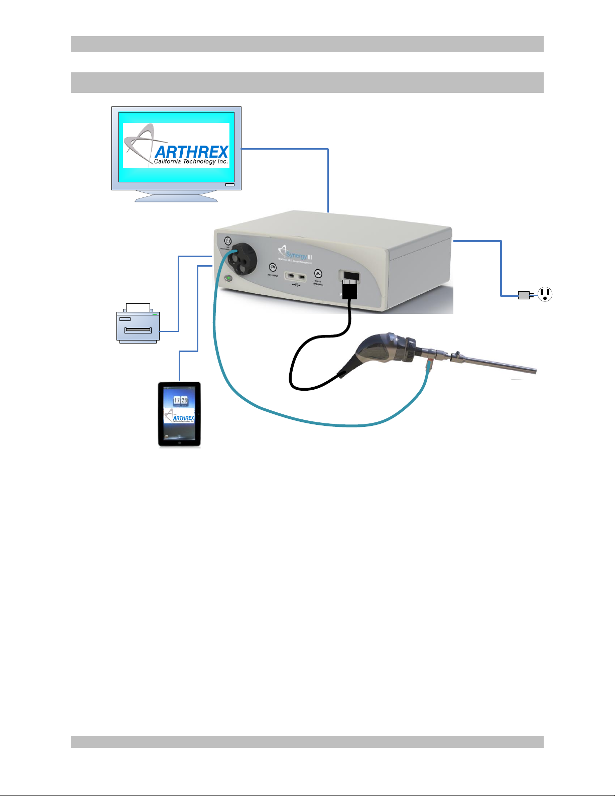
Figure 28 – Typical Synergy HD3 System and Peripherals
3.1 Scope
This document covers the theory of operation of the Synergy HD3 camera system. It includes the
CCD camera Head, its connection and synchronization to the Camera Control Unit, and Video
Processing to create High Definition video outputs.
This is a high level overview; refer to Software and Firmware Requirements documents for
detailed descriptions of those operations.
3.2 General Design Goals
Considerations in the design of this system fall into one of two categories, Essential Performance
and everything else.
3.2.1 Essential Performance
950-0078-00 A 39 of 69
Should all else fail, it is essential that the camera system make a viable color image on
the surgical monitor.
This is without undue interruption in image quality or disruption to the surgical procedure
due to a malfunction.
Page 40

950-0078-00, Rev. A English
In this regard, the signal path from CCD to video output can operate independently of any
software or microprocessor functionality. This also includes control and operation of the
integrated LED light source.
Additional Goals are:
A camera system optimized for Endoscopic Surgery
A synergy of High Definition Camera, LED light source, and Image Management
functionality
High quality and low noise video images
Ease of operation and user interface
Versatility for various procedures and environments
Appropriate cost of manufacture
Design Stability and ease of manufacture
The following design features are incorporated to achieve these goals:
Progressive scan Three-Chip CCD and prism
Powerful digital signal processing to enhance image quality
No unit-to-unit adjustments or calibrations
Interchangeable camera Heads without adjustment
Exclusive use of differential signaling to and from camera Head
Electrical isolation and safety independent of camera Head
3.2.2 Peripherals
The camera system is intended for use with a variety of peripherals as follows. See
Figure 28 for a typical setup and also refer to the SynergyHD3 operating manual.
Video monitors or recording devices utilizing DVI or HDSDI connections and a 1080p
format
Medical grade printers utilizing USB connections
USB memory and mass storage devices
Tablet computer devices as a user interface connected to a dedicated USB port
Ethernet communication and networking
Legacy accessory devices such as foot pedals
Auxiliary DVI video input device for picture-in-picture functions
3.3 Camera Control Unit
The CCU is intended to sit on a rack outside of the patient’s sterilized field. It provides power and
connection to the Camera Head and all peripherals.
3.3.1 CCU Sections
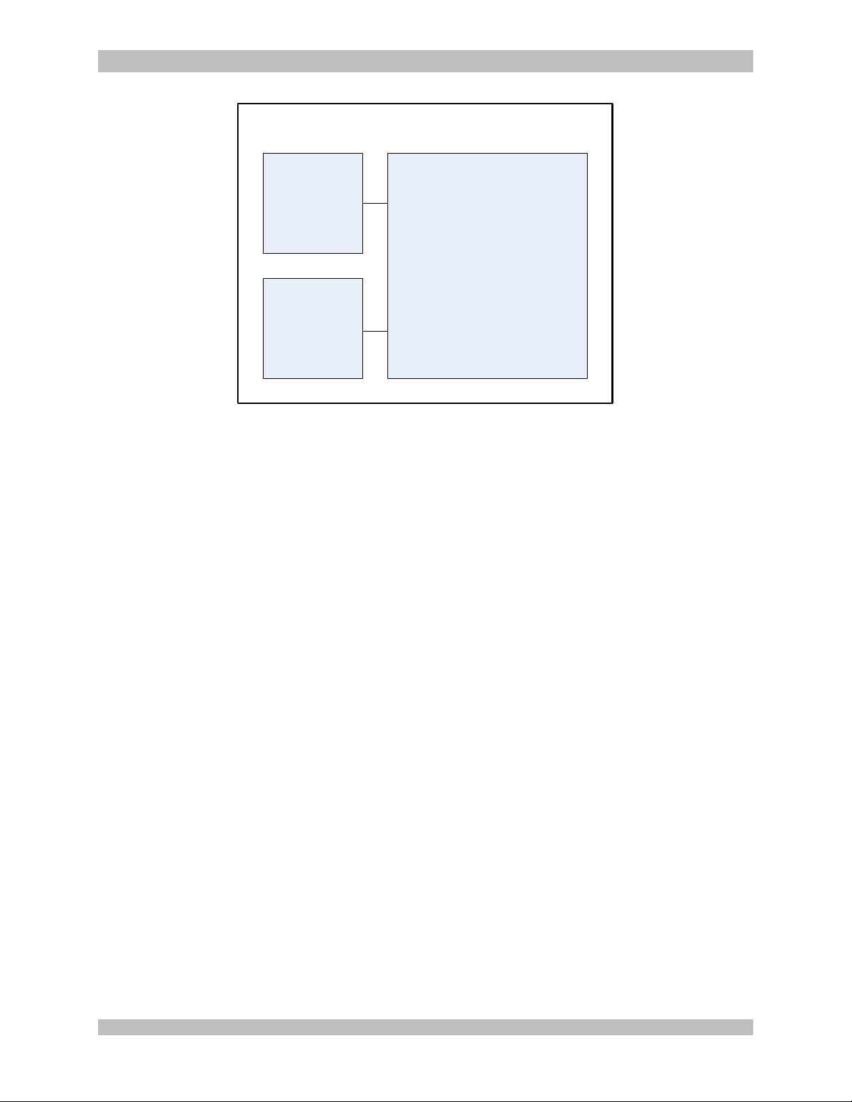
There are three major sections within a CCU chassis. The power supply, Light Engine,
and camera circuitry which consist of several boards mounted to a metal riser plate.
950-0078-00 A 40 of 69
Page 41
950-0078-00, Rev. A English
Power
Supply
Light
Engine
Camera
Circuitry
Camera Control Unit
The power supply section accepts universal AC input voltages for use in international
user environments. It provides +12V power for the entire system. This power is active
whenever AC is supplied, and is then switched On and Off by the camera circuitry in
response to the front power switch or software. Power defaults to On when AC is first
supplied.
The Light Engine consists of a high power LED and related control circuitry. It is
activated by camera control circuitry. This section also contains a cooling fan for the light
engine and entire chassis. The Light Engine is defaulted to Standby when AC power is
first applied to the CCU.
The Camera Circuitry handles all image processing and control functions, as described
below.
3.3.2 Overall CCU Circuitry
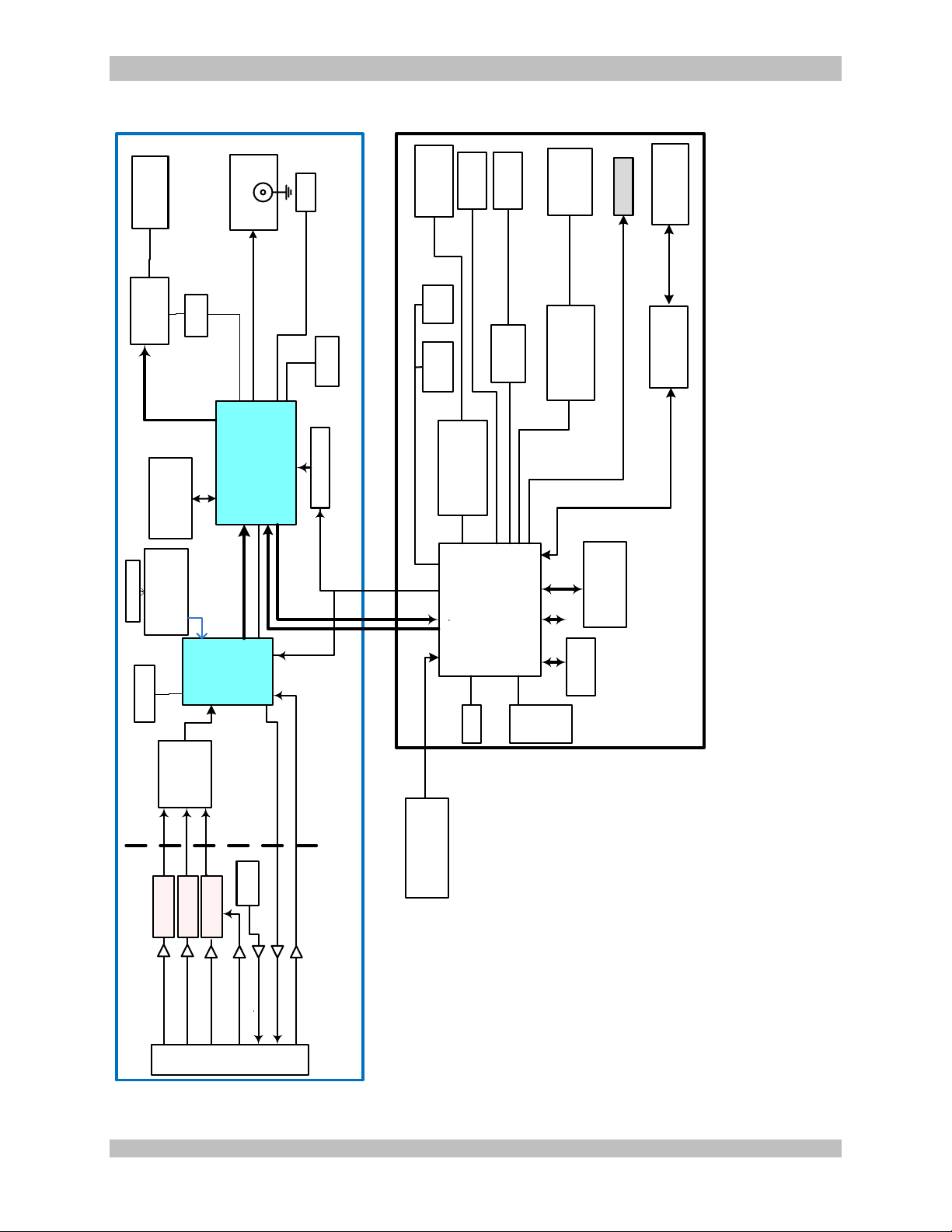
Figure 30 depicts the camera circuitry with those blocks providing Essential Performance
shown at its left. This is further discussed below, presented as a signal flow from CCD
sensor to a video monitor.
Blocks depicted in the right side of Figure 30 are under software control. They provide
for the user interface from a Tablet computer, recording of video stills and clips, and
printouts. Refer to Software Requirements documents for further details.
Software can also overlay information onto the main video image, along with (picture-inpicture) video images from the DVI input port. This functionality is defeated should there
be a software timeout error.
A membrane panel on the front of the CCU provides for control buttons and LED
indicators. These are split between the essential section (for Light Engine control and
White Balance) and the software section (for USB activity).
Figure 29 – CCU Sections
950-0078-00 A 41 of 69
Page 42
950-0078-00, Rev. A English
DaVinci DM8165
MPEG Encoder and embedded
controller running Linux
27MHZ Top Clock
Camera
Processing
FPGA
ECP3
HD
VID
I²C
GPIO
SATA/
SD Ports
PCIe
DDR 3
Memory
1GB
32MB NAND Flash
Memory
U-BOOT (OS on SD)
DDR
GPMC
Ethernet1
Ethernet Phy
Micrel
KSZ9051MLL
25MHz Crystal
USB
Connector (4)
Front/Rear
UARTS
Formatter FPGA ECP3
Scale, overlay and still capture
Clocks:
148.00MHz (Memory and GPMC)
148.00MHz (DVI)
3G HD-SDI Outputs
Dual
FPGA I²C
Option
Overlay Interface
GPMC (Header)
16 Bit
GPMC
JTAG Chain
and header
DDR3
Memory to support
scaling, overlay and
processing
USB 2.0 Hub
Pericom
PI7C9X440SL
Ethernet
Connector
Rear Panel 10/100
DVI
Silicon Image
SiI 164
DVI-I Outputs
Dual
CDS and FPGA
24-bit @ 148MHz
60 FPS
Progressive RGB
30/60 fps 1080P In/Out
Return 1X Clk
Up-Link/JTAG Shared
Dn-link/JTAG Shared
Oscillator
Pixel Clock
4x CLK
Deep Color
TMDS/DVI
12-bit Data X3
CDS and FPGA
CDS and FPGA
SPI
DDR3
Port
Red
Green/JTAG Shared
Blue/JTAG Shared
Camera Head
Input Connector
I²C To
Devices
GPIO
Header
and 4
GPIOs to
Formatter
FPGA
Isolated Camera Input
Module Section—See MM
block Diagram
GPMC
Pixel Clock 46.2MHz
24 bit @
108MHz RGB
16 Bits @ 108 MHz
32 Bits @ 400 MHz
Clock Generator
Lattice ISP5610 and
SiLabs Clock Cleaner
148.35/5 MHz,
Main Oscillator
RS232 to
Rear panel
(Isolated)
Acc Ports
HD-SDI
HD VID
Audio Connectors
(Mic and Line out)
Front/Rear
Video Input Board
DVI
GIG-E Ethernet
Connector
(Internal)
Ethernet
GIG-E PHY
Micrel KSZ9021GN
25MHz Crystal
Ethernet0
HDMI Output
Audio Support
A/D and D/As
TLV320AIC3106
Non-Isolated Camera
Input Section
Isolation
Barrier
DDR3
Memory
16 Bits @ 400 MHz
RS232
Debug
Port
USB
Connector (2)
Internal
DVI Receiver
Silicon Image
SiI 1161
ESSENTIAL PERFORMANCE
Figure 30 – CCU Circuitry Block Diagram
950-0078-00 A 42 of 69
Page 43
950-0078-00, Rev. A English
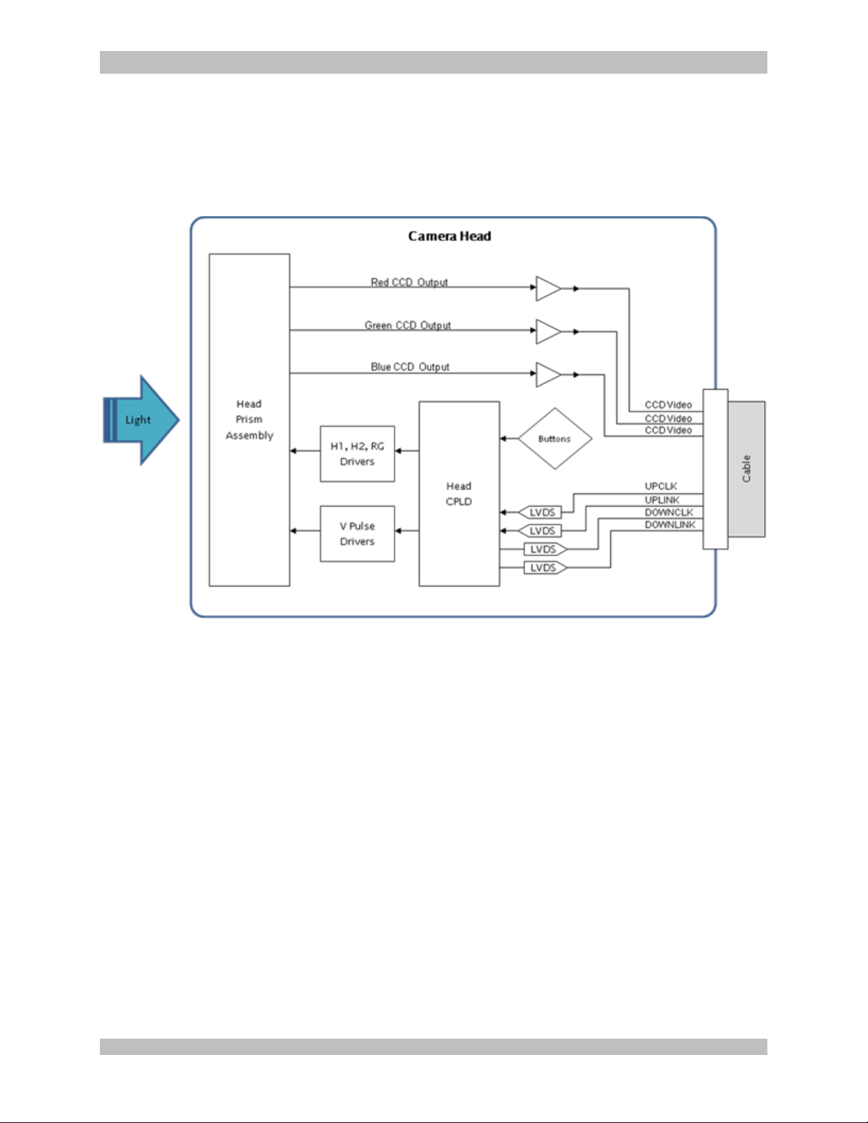
3.4 Camera Head
The Camera Head is a hand held device intended for use within the sterile field and contact with
a patient. It connects to the front panel of a CCU through a cable. The grasping mechanism then
couples to an endoscope and light guide for imaging.
Figure 31 – Camera Head Circuitry Block Diagram
3.4.1 Power
Power is supplied to the Head in the form of four voltages which are further regulated
within the Head. This secondary regulation offers enhanced noise reduction, immunity to
EMI such as cautery noise, and correction for cable loss. Regulated voltages include
+12V, +5V, +3.3V, and -5.5V distributed through several LDOs which also serve to
separate noise sensitive areas of the circuitry.
Sequencing within he CCU insures that the negative supply is not applied until the Head
is connected and operating, to avoid damage to the CCD. Sequencing within the Head
also insures that the +12V supply is not activated until +3.3V is up and running, to protect
the CCD. Plug contacts are also at staggered lengths to engage ground and power
before signals.
3.4.2 Timing and Synchronization
The CCU provides a clock (UPCLK) and data signal (UPLINK) for synchronizing and
communicating with the Head. UPCLK provides a means for qualifying the data in
UPLINK as well as providing a master clock for the Head. UPLINK is a serial data stream
containing vertical sync information for synchronizing the head. UPLINK also contains
data for setting exposure time.
950-0078-00 A 43 of 69
Page 44

950-0078-00, Rev. A English
Both UPCLK and UPLINK are transmitted up the cable to the head via LVDS transmitters
and twisted-pairs in the cable. The LVDS signals are received in the head with LVDS
receivers and then sent directly to the head CPLD.
3.4.3 CCD Control
Three CCD sensors are attached to a prism assembly with color separation into Red,
Green, and Blue spectrums. These sensors are driven by a complete timing generator
within the CPLD. Horizontal signals are sent through drivers for H1, H2, HL, and RG
pulses for each sensor. Vertical clocks V1, V2, V3, V4 and shutter pulses are sent
through a shutter pulse driver for each sensor.
3.4.4 CCD Video Output
The analog signal from each CCD is then buffered with a wide bandwidth emitter
follower. The buffered signal is AC coupled into a high speed differential amplifier which
provides 2X gain. These differential CCD video signals are then driven down a twisted
pair cable and received by the CCU.
3.4.5 Return Clock and Data
The Head provides the CCU with a clock (DOWNCLK) and data (DOWNLINK) for
returned information. This DOWNCLK is at the CCD pixel rate and is used by the CCU
circuitry to synchronize video data conversion. Data from the Head is encoded into the
DOWNLINK path which is qualified by the DOWNCLK.
Both DOWNCLK and DOWNLINK are transmitted down the cable to the CCU via LVDS
transmitters and twisted-pairs in the cable. The LVDS signals are received in the CCU
with LVDS receivers and then sent directly to its FPGA.
3.4.6 Buttons
The Head CPLD detects the movement of two Hall-effect buttons through the use of an
ADC converter. This position information is continuously sent down the DOWNLINK for
interpretation by the CCU.
3.5 Head Interface
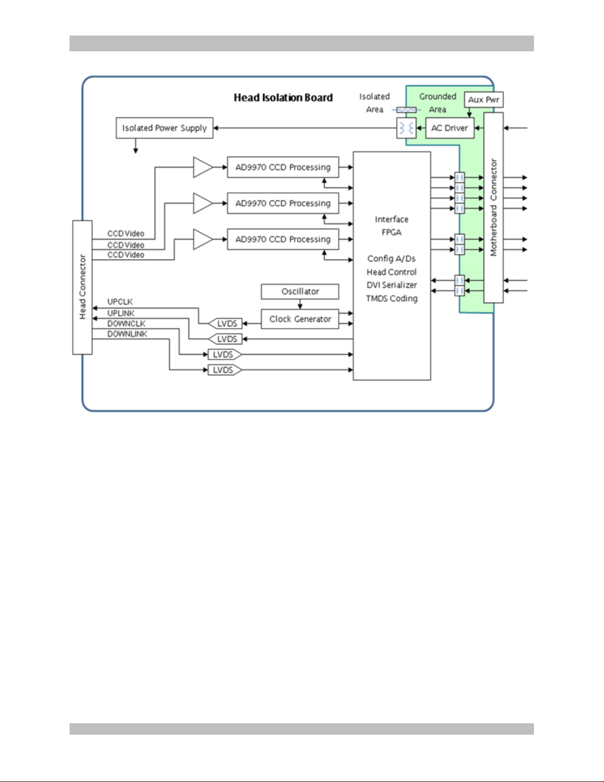
Within the CCU is a receptacle for the Head cable and interface circuitry for the Head. The Head
Isolation Board provides this interface. Camera Heads are interchangeable and can be
connected and disconnected at any time.
950-0078-00 A 44 of 69
Page 45
950-0078-00, Rev. A English
Figure 32 – Head Isolation Board Circuitry Block Diagram
3.5.1 Power
Regulated power is supplied to the head at voltages high enough to accommodate cable
losses and LDO dropout voltages within the Head. The FPGA has control of the negative
voltage rail which is held off until a DOWNCLK is detected.
3.5.2 Clocking
A crystal oscillator on the Isolation board provides the reference clock to a clock
synthesizer chip. This synthesizer can then generate any desired frequency to drive the
Head UPCLK and CCD. This UPCLK also is used to clock UPLINK data.
3.5.3 Data
Data and clock from the Head is received by differential receivers and sent directly to the
FPGA circuitry.
3.5.4 Video Input
Differential video signals from the Head are received and converted to digital form by
high speed ADC converters which incorporate Correlated Double Sampling (CDS) front
ends. Each of the three colors is converted to two serial data streams and an associated
data clock for conveyance to the FPGA. This FPGA includes a timing generator driving
950-0078-00 A 45 of 69
Page 46

950-0078-00, Rev. A English
the CDS with VD and HD pulses synchronized to the DOWNCLK. ADC conversion
timing is driven directly by the DOWNCLK.
The ADC internally generates CDS video sampling pulses (SHP, SHD) which can be
adjusted through its SPI interface to the FPGA.
3.6 Isolation
Patient safety is provided by an isolation barrier within the CCU. In the event that a
patient or camera Head inadvertently becomes electrically energized, the CCU will not
provide a path to ground. In the event that the patient becomes grounded, the CCU will
not induce unsafe leakage currents to that ground.
3.6.1 Power
The isolation board provides up to 10W of isolated power for its circuitry and the Head.
3.6.2 Control
Communication with the remaining camera circuitry is isolated through data transformers.
This provides synchronization and control of the Head and reading of button presses.
3.6.3 Video Data
Video signals from the Head receive preliminary processing within the isolation board
Interface FPGA and is serialized for transmission across the isolation barrier through data
transformers. This serialization utilizes DVI protocols with 12 bit deep color data
encoding.
3.7 Motherboard
The CCU motherboard forms a hub of connectivity and control for the entire system, as
shown in Figure 30.
3.7.1 Power
The single +12V power supplied to the motherboard is switched on and off in response to
the front panel push button. It is then regulated and distributed further.
3.7.2 Video Processing
Video from the isolation board is received and deserialized on the motherboard and fed
to the Video Processing FPGA.
A White Balance block provides independent gain for the red, green, and blue data
values. The white balance system averages the red, green, and blue pixel values within a
window in the center of the active image. The color with the highest average has its
corresponding gain set to 1. The system then calculates the gain for the remaining two
colors, which will each be greater than 1. This operation is performed in response to
pressing the front panel White Balance button or a Head button so programmed.
A gamma correction block consists of three lookup tables for each of the RGB channels.
Each table contains the same gamma function, which is designed to provide the most
natural looking image without excessive gain in the dark areas of the image.
950-0078-00 A 46 of 69
Page 47

950-0078-00, Rev. A English
The RGB data is colorspace-converted to YCrCb for the purpose of edge enhancement.
There are three components to the edge enhancement block. The luminance (Y)
component is passed through a convolution kernel which has a zero DC component
(Laplace). This kernel is designed for accentuating mid spatial frequencies. The resulting
edge information is multiplied by a constant, and the result is added back in to the original
Y data. The degree of edge enhancement is controlled by the multiplication constant.
3.7.3 Video Formatting
Data from the Video Processing FPGA is then sent to the Formatting FPGA to drive video
outputs to a monitor. Data is passed through a scaler to expand the image size to 1080p.
The YCrCb data is serialized and passed to an HDSDI driver to provide two serial video
outputs.
Data is converted back to RGB space and passed to the DVI Driver. The Formatter
FPGA also provides the sync signals to the DVI driver. Two DVI drivers output the DVI
signals to the DVI connectors on the back panel of the CCU.
The entire system frame rate, from the Head down, is synchronized to this DVI output
formatting.
3.8 Programming
Proper functioning of the camera system relies on programming of software and firmware.
3.8.1 Head
When plugged into a special version of the isolation board, the camera Head goes into
programming mode. The UPLINK and DOWNLINK lines are switched over to JTAG lines
when +12V in not present. This allows for JTAG connection to the CPLD for
programming.
3.8.2 Isolation FPGA
A JTAG cable must be connected to the isolation board during manufacturing in order to
program its FPGA.
3.8.3 Motherboard FPGAs
A JTAG cable connected to the motherboard during manufacturing allows for
programming both the Processor and Formatter FPGAs.
3.8.4 Software
An SD Card inserted into the motherboard provides software for the operation of its CPU.
950-0078-00 A 47 of 69
Page 48

950-0078-00, Rev. A English
4.0 Maintenance
Regular and proper maintenance of your
Synergy
the best ways to protect your investment and
avoid non-warranty repairs.
Recommended care and handling of the
Synergy
camera head includes proper day-to-day
operation, cleaning, and sterilization which are
extremely important to ensure safe and efficient
operation. It is important to visually inspect the
camera head, cable and card edge before each
use.
Your authorized Arthrex service department is
the most knowledgeable about the Arthrex
Medical Camera Systems and/or camera heads
and will provide competent and efficient service.
Any services and/or repairs done by any
unauthorized repair facility may result in reduced
performance of the instruments or instrument
failure.
4.1 Life Expectancy
The standard warranty for this product is twelve
months. Life expectancy for the product is
expected to meet and exceed this period for
approximately 5 years under normal use and
standard of care.
4.2 Periodic Maintenance
The product should be inspected prior to and
after each use to ensure that the camera head,
cable, strain relief, overmold, or connector
contacts are not damaged or worn. If it becomes
necessary to return the camera head to Arthrex
for service, please sterilize the camera head
before shipping.
4.3 Cleaning and Sterilizing
Follow universal precautions for protective
apparel when handling and cleaning
contaminated instruments.
HD3
and/or AR-3210 Camera Heads are
HD3
Camera Control Unit (CCU) and
4.3.1 Cleaning the Camera Control Unit
(CCU)
1. Turn the CCU power off. Disconnect
the power cord from the electrical
power source and from the rear of the
CCU.
2. Remove the camera head from
the CCU.
3. Wipe the CCU with a clean, soft cloth
dampened with a mild, pH- balanced
detergent.
4. Wipe the CCU again with Tap or
sterilized water.
5. Dry the CCU with a clean, soft cloth.
CAUTION: Do not sterilize the CCU or
immerse it in liquids or disinfectant solution.
950-0078-00 A 48 of 69
Page 49
950-0078-00, Rev. A English
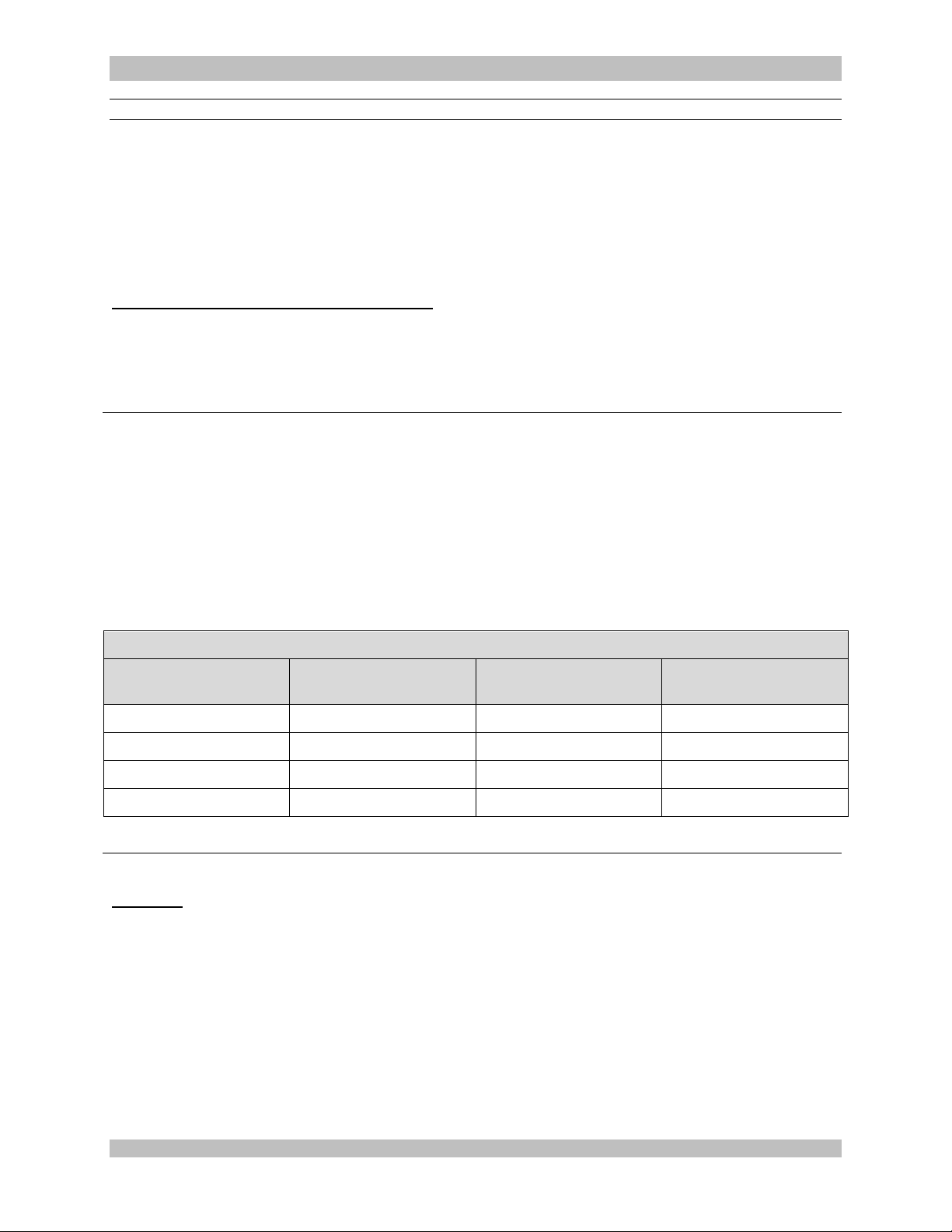
Automatic Washer Cycle Definition
Phase
Recirculation Time
(Minutes)
Temperature
Detergent Type and
Concentration.
Pre-Wash 1
02:00
Cold Tap Water
NA
Enzyme Wash
03:00
Hot tap water
Enzol® 1oz/gallon
Rinse 1
00:15
Hot tap Water 60oC
NA
Drying
06:00
90oC
NA
4.3.2 Cleaning the Camera Head
CAUTIONS:
If the camera head is dented or damaged, or if the connector jacket is cut, DO NOT
autoclave or immerse in liquid (water, chemical disinfectants or sterilants, etc.). Notify
your Arthrex Sales Representative.
Do not place the camera head or accessories in an ultrasonic cleaner or washer/sterilizer.
Preparation for Cleaning and Sterilization
Immediately after use, place the camera head assembly in a container and soak with neutral pH (PH 6.0 –
8.0) enzymatic cleaning solution (e.g. Enzol, Metrizyme or equivalent diluted to proper concentrations per
manufacturer’s instructions), in order to prevent blood, protein and other contaminants from drying onto the
camera head.
4.3.2.1 Automated Cleaning
Use only washers according to the International Standard ISO 15883.
Refer to the washer’s instruction manual.
1. Transfer the camera had into the washer for processing.
2. Make sure that the camera head has been securely fixed to the unit’s trays or baskets. Make sure
that the camera head does not touch other instruments.
3. Do not overload the washer.
4. Remove the camera heads immediately after the automatic procedure has stopped.
5. Set up washer for the wash cycle listed below.
4.3.2.2 Manual Cleaning
CAUTION: Wear protective gloves, clothing and face mask for cleaning of contaminated equipment.
1. Immediately after use, Rinse the camera head under cool running tap water to remove the gross
2. Prepare a neutral enzymatic detergent, such as Enzol®, using tap water at 1 oz/gallon.
3. Fully immerse the camera head in the prepared solution and allow it to soak for a minimum of 10
4. After soaking, use a soft bristled nylon brush to remove all visible evidence of debris and soil. Pay
950-0078-00 A 49 of 69
soil. Use a soft bristled brush to aid in the removal of soil paying particular attention to hard-toclean areas.
minutes. Flush hard to reach areas to ensure all soil is removed. While soaking activate movable
parts.
close attention to the card edge connector.
Page 50
950-0078-00, Rev. A English
Sterilization Protocols Validated
PRECAUTION: After sterilization, set the AR-3210 Camera Heads aside for 15 minutes to allow equipment to cool before
connecting to the CCU or attaching to a scope.
Sterilization
Protocol
Details
Steris Systems
AR-3210-XXXX Camera Heads are validated for Sterilization Assurance using the Steris systems listed
below, and following the manufacturer’s instructions.
V-PRO 1 Plus [Non-Lumen Cycle]
V-PRO maX [Non-Lumen Cycle]
V-PRO 1
Sterrad System 100S
Sterrad System NX
Sterrad System 100NX
AR-3210 Camera Heads are validated for Sterilization Assurance using the Sterrad System 100S,
System NX and System 100NX. Follow the Sterrad Instructions for use.
STEAM STERILIZATION PARAMETERS
Method
Cycle
Minimum
Exposure
Temperature
Exposure Time
Dry Time
Steam (Wrapped)
Pre-vacuum
132° C (270° F)
4 Minutes
30 Minutes
Steam (Wrapped)
Gravity
132° C (270° F)
15 Minutes
30 Minutes
Steam (Un-Wrapped)
Gravity
132° C (270° F)
10 Minutes
NA
5. Rinse the camera head by immersing it in a basin of warm tap water. Allow the camera head to
sit in the water for a minimum of 1 minute, while soaking activate movable parts. .
a. Repeat step 5 two additional times using fresh warm tap water each time.
b. Rinse under running tap water to ensure water reaches hard to reach areas. Activate
while rinsing until all visible evidence of detergent is removed.
6. Visually inspect the camera head for visible soil and remove if required.
7. Dry the equipment with a lint-free soft cloth. Wipe the card edge connector with 70% isopropyl
alcohol to remove any residual detergent.
a. Do not allow exposed glass windows to air dry. 70% isopropyl alcohol may be
applied to glass surfaces with a soft cotton applicator to prevent streaks and
spots. Dry the surfaces thoroughly with a cotton applicator after applying the
alcohol.
8. After cleaning, inspect the camera head assembly and camera head cable for cleanliness and
damage.
9. CAUTION: Inspect the camera head cable for breaks and cuts. Camera heads with damaged
cables should not be sterilized or disinfected. Return camera heads with damaged cables to
Arthrex for repair.
10. Before sterilization and/or disinfection, coil the camera head cable into loops at least six inches in
diameter. Do not kink or twist the cable.
4.3.3 Sterilization of the AR-3210 Camera Heads
950-0078-00 A 50 of 69
Page 51
950-0078-00, Rev. A English
Symptom
Possible Cause
Corrective Action
Camera does not
power up. Standby
LED does not
illuminate.
Power cord is unplugged.
Suspect power cord.
Plug power cord into CCU and/or a
properly grounded receptacle.
Replace power cord.
Intermittent picture.
Verify camera head connector
card edge is fully inserted into
the CCU camera receptacle.
Suspect video and/or power
cables.
Suspect camera head or cable.
Reinsert camera head connector card
edge.
Flex video and power cables. If picture
is affected, inspect cables and replace
as necessary.
Flex camera cable. If picture is
affected, return to factory for repair or
replacement.
Camera will not white
balance.
Too much light.
Too little light.
Wrong Color Temperature
light.
If monitor indicates “White Balance
Fail”, move the scope further away
from the white gauze when you white
balance, or turn down the light source
brightness.
IF this does not resolve the problem,
If monitor indicates “White Balance
Fail”, move the scope closer to the
white gauze when you white balance,
or turn up the light source brightness.
Camera Head Buttons
do not function as
programmed.
Incorrect camera head button
programming.
Reprogram camera head buttons.
NOTE: Tablet Data Input device option
only.
4.3.4 Material Compatibilities
In addition to the Sterilization chemicals listed above, the AR-3210 camera heads are Material
Compatible with Cidex OPA. No SAL claims are made with Cidex OPA.
WARNING: Use of Sterilants or Chemicals other than those listed in the Cleaning and
Sterilization section may result in the compromise of the device’s safety and effectiveness. Use
of Sterilants or Chemicals other than those listed in the “Cleaning and Sterilization” section shall
void the product’s warranty.
4.4 Troubleshooting
950-0078-00 A 51 of 69
Page 52

950-0078-00, Rev. A English
Symptom
Possible Cause
Corrective Action
No video image on monitor.
CCU and/or monitor are not
ON and/or plugged in.
Equipment is not connected
properly or cable(s) damaged.
Suspect camera head and/or
cable.
Camera head cable connector
not inserted correctly or
completely.
Plug CCU and/or monitor in
and/or turn power ON.
Confirm cable connections
and reroute video cables, if
necessary per interconnect
diagram. Check video cables
for damage, replace as
necessary.
Replace the camera head
with a working unit and verify
image on monitor. If image is
now viewed, the original
camera head and/or cable
were faulty, return them to
Arthrex for repair.
Insert camera head cable
connector completely into the
console’s camera head
receptacle on the front panel.
Check monitor using color
bars from the CCU.
Try the CCU on a different
monitor.
Poor color reproduction.
White Balance Issues.
White Balance camera head
Check monitor settings using
color bars from the CCU.
Try the CCU on a different
monitor.
950-0078-00 A 52 of 69
Page 53
950-0078-00, Rev. A English
Test Type
Test Value
Ground Impedance
ZG < 100 mOhm from the ground pin on the power inlet module to
the Camera Control Unit’s exposed metal parts. *
Test Chassis Leakage Currents
IL < 100 uA in NORMAL Condition.
IL < 500 uA in Single Fault Conditions [300 uA US deviation] *
Test Earth Leakage Currents
IL < 500 uA NORMAL Condition [300 uA US deviation]
IL < 1 mA Single Fault Condition *
Test Dielectric Withstand
Test Line and Neutral to Ground @ V = 1500 V~, no breakdown *
* See IEC 60601-1 for test methods.
4.5 Recommended Annual Camera Control Unit Maintenance Requirements
Recommended Annual Camera Control Unit Maintenance Requirements
950-0078-00 A 53 of 69
Page 54

950-0078-00, Rev. A English
Required Equipment
Monitor and Power Cord
DVI or SDI Cable
Arthrex Tablet Kit (Part Number AR-3200-1004, AR-3200-1006, or AR-3200-1008)
Light Guide (Wolf)
Arthrex Camera (Part Number 983-0002-XX)
Printer and Power Cord
Printer Paper
Printer Ribbon
USB-A to USB-B Cord (for Sony Printer)
iPad with the most recent iTunes release of the Synergy HD3 Surgeon Application installed and
iOS6
iPad to USB Cable
USB Stick
Endoscope
Ethernet Cable
Wireless Router and Power Cord
5.0 Troubleshooting (Tests)
5.1 Physical Check
5.1.1 Place CCU on testing work bench
5.1.2 Check the CCU for external damage, including damage to the USB ports, the
rear panel connections and the camera head receptacle.
5.1.3 Verify the LED ON/STANDBY and White Balance buttons can be pressed
and will return to their original starting position.
5.2 CCU Set Up
5.2.1 Take a complete tablet set (Docking Station, Exoskeleton, Cord, and Tablet)
and plug the USB Cord from the Tablet into the Tablet USB Port in the back
of the CCU.
5.2.2 Plug the Printer USB Cord into the bottom USB port on the back of the CCU.
5.2.3 Plug a DVI, or SDI Cable into the back of the CCU. Make sure the monitor is
correctly connected. Power the Tablet on and apply power to the CCU.
The printer icon on the monitor will show a green bar below. (Note: Older
models will show a green circle with a black check mark in the circle.)
950-0078-00 A 54 of 69
Page 55

950-0078-00, Rev. A English
a. If the Tablet is in Kiosk Mode:
AR-3200-1008 (12” Tablet) only: If Tablet is in Kiosk Mode, double tap
on the tablet screen (anywhere other than login fields) and tap
‘Advanced Options’. A few options will display on the screen. Tap
‘Toggle Kiosk Mode’. Enter ‘synergy’ as password.
All other Tablets: If tablet is in ”Kiosk” mode press and hold the top left
button on the tablet, then tap device options, enter “1111” for the pin, and
tap “ok”
b. If the CCU is in Rescue Mode, indicated by alternately flashing blue front
membrane LEDs, restart the CCU to get it out of Rescue Mode.
The following steps may also be used (for CCUs with v1.5 or v3.5 or
previous software versions) to exit rescue mode via a wireless router.
Ensure router is plugged in and on. Connect an Ethernet cable from the
Ethernet port on the router to the Ethernet port on the back panel of the
CCU. Navigate to the 192.168.1.2 URL on the iPad using the Safari
browser. Tap the ‘exit rescue mode’ button. Wait for the message,
“Rescue Mode disabled…” and restart the CCU. Confirm the system is
not in rescue mode and is ready for use.
5.3 Verify Tablet Charges
5.3.1 Navigate to the home screen of the tablet, if you are not already there.
5.3.2 If not at home screen of the tablet, hit the home button in the lower left corner
of the tablet.
5.3.3 Tap the “Settings” icon, which looks like a “gear wheel” or sprocket.
5.3.4 Scroll to and tap “Battery”. Verify tablet is charging.
5.4 Force quit the Arthrex Controller Application manager
5.4.1 Scroll down to “Applications manager”.
5.4.2 Tap “Applications manager”.
5.4.3 Tap “Arthrex Controller” on the right side of the tablet.
5.4.4 Tap “Force stop”.
5.4.5 Tap “OK”.
5.4.6 Tap “Clear data”
.
5.4.7 Tap “OK”.
5.5 Enter “Kiosk” mode
5.5.1 CCUs with 1.x or 3.5 or previous software versions
a. Tap the home button.
950-0078-00 A 55 of 69
Page 56

950-0078-00, Rev. A English
b. Tap the App icon (16 white squares).
c. Tap “KioskMode”.
d. Tap “OK”.
5.5.2 For all other CCUs
a. Tap the home button.
b. Tap the App Icon (16 white squares).
c. Navigate and select “Arthrex Controller” icon.
d. Double tap on the tablet screen (anywhere but the login fields).
e. Tap on “Advanced Options”.
f. Tap on “Toggle Kiosk Mode”.
g. Enter password, ‘synergy’.
5.6 Light guide and green LED check
5.6.1 Plug the light guide into the CCU. Press light guide button and make sure the
light guide illuminates and a green LED light lights up on the button.
5.6.2 Verify a green LED light is lit on the power button.
5.7 Image Check
5.7.1 Install the endoscope onto Camera.
5.7.2 Attach Light Guide to Scope.
5.7.3 Insert the Camera Head plug into the CCU.
5.7.4 Verify a live picture is present on the monitor.
5.8 Connectivity Check
5.8.1 Restart the CCU.
5.8.2 Press and hold power button on CCU for about five seconds.
5.8.3 Press the power button to turn on.
5.8.4 Verify the Tablet reconnects to the CCU.
Note: Tap the tablet to reconnect if necessary.
5.8.5 Verify banners appear on both side of the monitor after approximately one
minute from power on.
950-0078-00 A 56 of 69
Page 57

950-0078-00, Rev. A English
5.9 Test Case Check
5.9.1 Verify the “Cases” screen is shown.
5.9.2 Tap the “Add New Case” button.
5.9.3 Tap surgeon drop down bar and select “Surgeon”.
5.9.4 Tap procedure drop down bar and select any procedure.
5.9.5 Tap Patient “First Name” and insert the serial number of the CCU.
5.9.6 Tap “Start” and “Start” again.
5.9.7 Tap the “gear wheel” on the left side.
5.9.8 Tap the printer icon.
5.9.9 Select “No. of Copies” to 1.
5.9.10 Tap the “gear wheel” icon again to remove preference settings screen.
5.10 White balance CCU
5.10.1 Make sure the Light Engine is on.
5.10.2 Take a white object and place it in front of camera.
5.10.3 Click one of the camera buttons to white balance.
5.10.4 Verify, “White balance OK”.
5.10.5 Take one still by pressing the left camera button one time.
5.10.6 Take one video, approximately ten seconds in length, by pressing the right
camera button to start, and again to stop.
5.10.7 Verify the video and still are present in the above thumb nails on the tablet
Note: Tap picture icon to view still.
5.10.8 Tap the “End Case” button in the lower right corner.
5.10.9 Tap “Yes, proceed to review”.
Note: The captured still will be auto printed at this time (print may take up to
one minute to start). Verify that the CCU serial number is on the print.
5.10.10 Insert a USB stick and an iPad cord (connected to an iPad) in the front USB
ports on the CCU.
Note: Tap “Trust” on iPad if prompted.
5.11 On the tablet, tap “Export” and two options appear
5.11.1 Select the USB icon and verify the LED above the USB stick on the CCU
begins to blink.
950-0078-00 A 57 of 69
Page 58

950-0078-00, Rev. A English
5.11.2 When the LEDs stop blinking, remove the USB stick and verify that there is
one JPEG, one MPEG4, and one PDF file on the USB stick.
5.11.3 Tap “Export” button again, and this time select the “Apple” icon.
5.11.4 Verify export progress bar completes.
5.11.5 If application isn’t running, navigate to the home screen of the iPad and
select the Arthrex Surgeon icon.
5.11.6 On the Patient List, select the CCU Serial Number.
5.11.7 Verify the one still image and the video are present on iPad.
5.12 Tap “Finish Review” on Tablet
5.13 Delete the finished case in the archive file
5.13.1 Tap User Normal.
5.13.2 Tap the folder icon in the upper right corner, next to the “Add New Case”
button.
5.13.3 Type password: synergy (if prompted).
5.13.4 Tap “OK” (if prompted).
5.13.5 Click on the case and two buttons appear on the right side, a “Review” and
trash can icon
5.13.6 Select the trash can icon
5.13.7 Tap “Yes” to confirm delete.
5.13.8 Tap Log Out.
5.14 Final Check
5.14.1 Power cycle the CCU, by holding down the power button 3-5 seconds and
make sure the tablet becomes paired with the CCU. Wait for the banners to
be displayed on the monitor, which indicates software is loaded, for each
power cycle. Tap the tablet to reconnect if necessary
5.14.2 Disconnect the iPad.
5.14.3 Shut down the CCU.
5.14.4 Shut down the Tablet by pressing and holding power button on tablet
5.14.5 Unplug the power cord, printer, video cable, tablet cable, light guide, and
Camera from the CCU.
950-0078-00 A 58 of 69
Page 59
950-0078-00, Rev. A English
Parameter
Parameter Value
System Classification
FDA Class
Class II
EU Class
Class I
Health Canada Class
Class II
Safety Certifications
Domestic Certification
UL 60601-1:2003
ANSI/AAMI ES60601-1:2005
Canadian Certification
CAN/CSA-C22.2 No. 601.1-M90
CAN/CSA C22.2 No. 60601-2-18-01
CAN/CSA-C22.2 No. 60601-1:2008
CAN/CSA-C22.2 No. 60601-2-18:2011
EU Certification
CAN/CSA-C22.2 No. 601.1-M90 [IEC
60601-1 2nd Edition with Canadian
Deviations]
CAN/CSA C22.2 No. 60601-2-18-01 [IEC
60601-2-18 2nd Edition with Canadian
Deviations]
CAN/CSA-C22.2 No. 60601-1:2008 [IEC
60601-1 3rd Edition with Canadian
Deviations]
CAN/CSA-C22.2 No. 60601-2-18:2011
[IEC 60601-2-18 3rd Edition with
Canadian Deviations]
EMC Certifications
CISPR 11 EMC Class
Class A
CISPR 11 EMC Group
Group 1 [un-intentional radiator]
EMC Certification
Certification to EN 60601-1-2 Class A
Safety Certification Marking
CE Marking
CE Marking for MDD 93/42/EEC
6.0 Technical Information
NOTE: Technical data is subject to modification, revision and improvement without notice.
Table 3: Safety, EMC and Regulatory Requirements
950-0078-00 A 59 of 69
Page 60
950-0078-00, Rev. A English
Classification of Equipment
Parameter Value
According to protection against electric shock.
Class I [Grounded]
According to degree of protection against
electric shock.
Applied part is Type BF
According to Degree of protection against
harmful ingress of water.
Camera Control Units are Ordinary [IPX-0] no
protection.
Camera Head is IXP-7 [Protected against
temporary immersion in water]
According to the degree of safety in the
presence of Flammable Anesthetics
Equipment is NOT suitable for use in the
presence of flammable anesthetics.
According to the mode of operation.
Continuous
Parameter
Parameter Value
Power Requirements
Rated Voltage: 100 – 240 V~
Supply Frequency: 50-60 Hz
Power Input: 140 VA
Fuses: No user serviceable fuses
Video Outputs
3G-SDI [1080P] Video: 59.94 Hz, Progressive, SMPTE 425 Standard
DVI [1080P]: 1920 X 1080 Pixels Progressive Scan [1080P]
Vertical Scanning
Frequency
59.94 Hz
Signal to Noise Ratio
> 50 -dB
White Balance Range;
Integrated Optics Head
2000 to 10,000 K
White Balance Range
:C-Mount Head
3053 to 10,000 K
CCU Dimensions
Approximately: 16” [W] x 5” [H] x 13.5” [D]
40.6 cm [W] x 12.7 cm [H] x 34.3 cm [D]
CCU Weight
Approximately: 18 pounds
Camera Head
Dimensions
AR-3210-0001
Approximately
4.75” [L] x 2.0” [W], x 2.0 [H]
12 cm [L] x 5 cm [W] x 5 cm [H]
AR-3210-0003
Approximately:
3.125” [L] x 1.5” [W], x 2.0 [H]
8 cm [L] x 4 cm [W] x 5 cm [H]
AR-3210-0004
Approximately:
3.125” [L] x 1.5” [W], x 2.0 [H]
8 cm [L] x 4 cm [W] x 5 cm [H]
AR-3210-0007
3.125” [L] x 1.5” [W], x 2.0 [H]
Table 4: Safety, Classifications
Table 5: Specifications
950-0078-00 A 60 of 69
Page 61
950-0078-00, Rev. A English
Parameter
Parameter Value
Approximately:
8 cm [L] x 4 cm [W] x 5 cm [H]
Camera Head Weight
AR-3210-0001
Approximately: 18.7 ounces
C-MT Heads
Approximately: 16 ounces
Transport & Storage
Conditions
Ambient Temperature: -40°F to 122°F [-40°C to 50°C]
Relative Humidity: 10% to 90%, non-condensing
Atmospheric Pressure: 500 hPa to 1060 hPa
Operating Conditions
Ambient Temperature: +50°F to 95°F [10°C to 35°C]
Relative Humidity: 30% to 75%, non-condensing
Atmospheric Pressure: Altitudes ≤ 3000 m
Parameter
Parameter Value
LED Light Source
Specifications
Light output
≥ 1350 Lumens
Color Temp
7000 K Nominal
LED Life
> 30,000 hours
Light Guide Port
Wolf™ Standard
Light Guide Port
Turret
ACMI™ Standard, Storz™, Wolf™ and
Olympus™
DICOM Statement
DICOM Compatible with installation of AR-3200-1020 DICOM Key
Table 6: Light Source Specifications
Table 7: DICOM Specifications
950-0078-00 A 61 of 69
Page 62

950-0078-00, Rev. A English
7.0 APPENDIX [Detailed
EMC Information]
DETAILED EMC INFORMATION
NOTE: CE marked equipment has been tested
and found to comply with the EMC limits for the
Medical Device Directive 93/42/EEC [EN 55011
Class A and EN 60601-1-2]. These limits are
designed to provide reasonable protection
against harmful interference in a typical medical
installation.
The Equipment generates and can radiate radio
frequency energy and, if not installed and used in
accordance with the instructions, may cause
harmful interference to other devices in the vicinity.
However, there is no guarantee that interference
will not occur in a particular installation. If this
equipment does cause harmful interference with
other devices, which can be determined by turning
the equipment off and on, the user is encouraged to
try to correct the interference by one or more of the
following measures:
Reorient or relocate the receiving device.
Increase the separation between the
equipment.
Connect the equipment to an outlet on a
circuit different from that to which the other
device(s) is connected.
Consult the manufacturer or a field service
technician for assistance.
NOTE: The EMC tables and other guidelines that
are included in the Instruction Manual provide
information to the customer or user that is
essential in determining the suitability of the
Equipment or System for the Electro-magnetic
Environment of use, and in managing the
Electromagnetic Environment of use to permit
the Equipment or System to perform its
intended use without
disturbing other Equipment and Systems or
non-medical electrical equipment.
NOTE: Medical Electrical Equipment needs
special precautions regarding EMC and needs
to be installed and put into service according to
the EMC information provided in the
Accompanying Documents.
WARNINGS:
1. Portable and mobile RF communications
equipment can affect Medical Electrical
Equipment.
2. Use of accessories, transducers, and cables
other than those specified, with the
exception of transducers and cables sold by
the manufacturer of the equipment as
replacement parts for internal components,
may result in increased emissions and
decreased immunity of the equipment or
system.
3. The video equipment / system should not be
used adjacent to or stacked with other
equipment, and that if adjacent or stacked
use is necessary, the equipment or system
should be observed to verify normal
operation in the configuration in which it is
intended to be used.
4. Under extreme conditions of primary power
voltage sag [Primary voltage less than 60%
of mains] the device may require operator
intervention to recover lost image. Device
may have to be restarted by pressing
On/Standby Switch.
950-0078-00 A 62 of 69
Page 63
950-0078-00, Rev. A English
IEC 60601-1-2 Table 1
Guidance and manufacturer’s declaration – electromagnetic emissions
The Arthrex HD3 Video System is intended for use in the electromagnetic environment specified below. The customer or
the user of the Arthrex HD3 Video System should assure that it is used in such an environment.
Emissions Test
Compliance
Electromagnetic environment- guidance
RF emissions
CISPR 11
Group 1
The Arthrex HD3 Video System uses RF energy only for its
internal function. Therefore its RF emissions are very low and
not likely to cause any interference in nearby equipment.
RF emissions
CISPR 11
Class A
The Arthrex HD3 Video System is suitable for use
in all establishments other than domestic, and may be
used in domestic establishments and those directly
connected to the public low-voltage power supply
network that supplies buildings used for domestic
purposes, provided the following warning is heeded:
Warning: This equipment/system is intended for
use by healthcare professionals only. This
equipment/ system may cause radio interference or
may disrupt the operation of nearby equipment. It
may be necessary to take mitigation measures,
such as re-orienting or relocating the
Arthrex HD3 Video System or shielding the location.
.
Harmonic Emissions
IEC 61000-3-2
Class A
Voltage fluctuations /
flicker emissions
IEC 61000-3-3
Complies
Table System Cables
Type
Use
Shielded?
Ferrite?
Maximum Length
Power Cord
Supply Line Power to
the Box
No
No
2 M
BNC to BNC
Composite Video Out to
Monitor
Yes
No
1.8 M
4 Pin Mini DIN
Y/C Video Out to
Monitor
Yes
No
1.8 M
DVI
DVI Video Out to
Monitor
Yes
No
1.8 M
3 pin mini Stereo
Accessory Port
Yes
No
1.8 M
Ethernet
CCU to Computer
Yes
No
5 M
USB
CCU to Printer
Yes
No
1.8 M
950-0078-00 A 63 of 69
Page 64
950-0078-00, Rev. A English
IEC 60601-1-2 Table 2
Guidance and manufacturer’s declaration – electromagnetic immunity
The ARTHREX HD3Video System is intended for use in the electromagnetic environment specified below. The customer or user of the
ARTHREX HD3 Video System should assure that it is used in such an environment.
Immunity Test
IEC 60601 test level
Compliance Level
Electromagnetic environment - guidance
Electrostatic discharge [ESD]
IEC 61000-4-2
± 6 kV contact
± 8 kV air
± 6 kV contact
± 8 kV air
Floors should be wood, concrete or ceramic tile. If
floors are covered by synthetic material the relative
humidity should be at least 30%.
Electrical fast transient / burst
IEC 61000-4-4
± 2 kV differential mode
± 1 kV for input / output
lines
± 2 kV differential mode
± 1 kV for input / output
lines
Mains power should be that of a typical commercial
or hospital environment.
Surge
IEC 61000-4-5
± 1 kV differential
mode.
± 2 kV common mode.
± 1 kV differential
mode.
± 2 kV common mode.
Mains power should be that of a typical commercial
or hospital environment.
Voltage dips, short interruptions
and voltage variations on power
supply input lines
IEC 61000-4-11
< 5% UT
[> 95% dip in UT] for
0.5 cycle.
40% U
T
[60% dip in UT] for 5
cycles.
70% U
T
[30% dip in UT] for 25
cycles.
< 5% UT
[> 95% dip in UT] for 5
seconds.
< 5% UT
[> 95% dip in UT] for
0.5 cycle.
40% U
T
[60% dip in UT] for 5
cycles.
70% U
T
[30% dip in UT] for 25
cycles.
< 5% UT
[> 95% dip in UT] for 5
seconds.
Mains power should be that of a typical commercial
or hospital environment. If the user of the
ARTHREX HD3 Video System requires continued
operation during power mains interruptions, it is
recommended that the ARTHREX HD3 Video
System be powered from an uninterruptible power
supply or a battery.
Power Frequency [50/60 Hz]
magnetic field.
IEC 61000-4-8
3 A/m
3 A/m
Power frequency magnetic fields should be at levels
characteristic of a typical location in a typical
commercial or hospital environment.
NOTE: UT is the a.c. mains voltage prior to application of the test level.
950-0078-00 A 64 of 69
Page 65
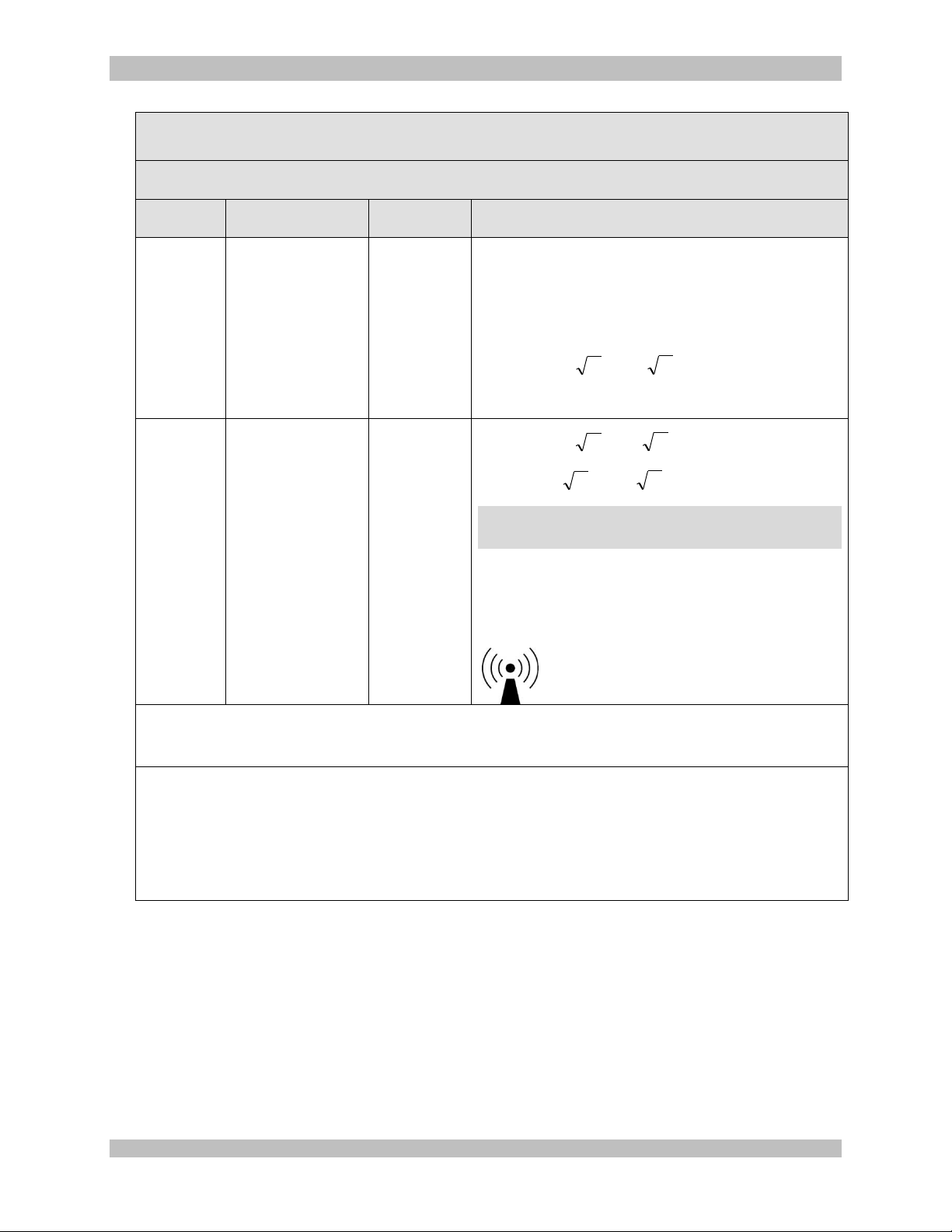
950-0078-00, Rev. A English
IEC 60601-1-2 Table 4
Guidance and manufacturer’s declaration – electromagnetic immunity
The ARTHREX HD3 is intended for use in the electromagnetic environment specified below. The customer or user of the
ARTHREX HD3 should assure that it is used in such an environment.
Immunity
Test
IEC 60601 test level
Compliance
level
Electromagnetic environment – guidance
Portable and mobile RF communications equipment should be
used no closer to any part of the ARTHREX HD3 Video System,
including cables, than the recommended separation distance
calculated from the equation applicable to the frequency of the
transmitter.
Recommended separation distance
Conducted
RF
IEC 61000-
4-6
3 Vrms
150 kHz to 80 MHz
V1=3 Volt
PVd 1/5.3
= 1.17
P
Radiated RF
IEC 61000-
4-3
3 V/m
80 MHz to 2.5 GHz
E1= 3 V/m
PVd 1/5.3
=1.17
P
80 MHz to 800 MHz
PEd 1/7
= 2.33
P
800 MHz to 2.5 GHz
Where P is the maximum output power rating of the transmitter in
watts [W] according to the transmitter manufacturer and d is the
recommended separation in meters [m].
Field strengths from fixed RF transmitters, as determined by an
electromagnetic site survey,a should be less that the compliance
level in each frequency range.
b
Interference may occur in the vicinity of equipment marked with
the following symbol:
NOTE 1: At 80 MHz and 800 MHz, the higher frequency range applies.
NOTE 2: These guidelines may not apply in all situations. Electromagnetic propagation is affected by absorption and
reflection by structures, objects and people.
a
Field strengths from fixed transmitters, such as base stations for radio [cellular/cordless] telephones and land mobile
radios, amateur radio, AM and FM radio broadcast and TV broadcast cannot be predicted theoretically with accuracy. To
access the electromagnetic environment due to fixed RF transmitters, and electromagnetic site survey should be
considered. If the measured field strength in the location in which the ARTHREX HD3 Video System is used exceeds the
applicable RF compliance level, above, the ARTHREX HD3 Video System should be observed to verify normal operation.
If abnormal performance is observed, additional measures may be necessary, such as reorienting or relocating the
ARTHREX HD3 Video System.
b
Over the frequency range 150 kHz to 80 MHz, field strengths should be less than 3 V/m.
950-0078-00 A 65 of 69
Page 66
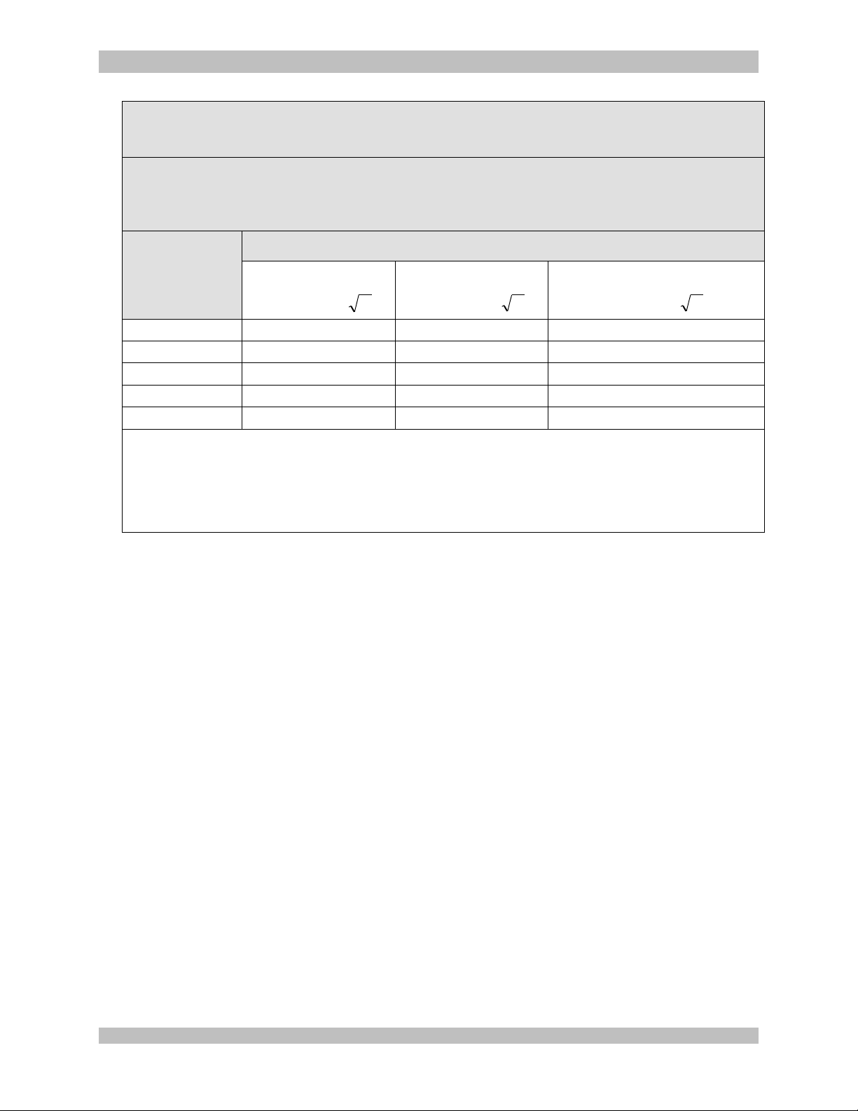
950-0078-00, Rev. A English
IEC 60601-1-2 Table 6
Recommended separation distances between portable and mobile RF communications equipment and the ARTHREX
HD3 Video System
The ARTHREX HD3 Video System is intended for use in an electromagnetic environment in which radiated RF disturbances
are controlled. The customer or the user of the ARTHREX HD3 Video System can help prevent electromagnetic interference
by maintaining a minimum distance between portable and mobile RF communications equipment [transmitters] and the
ARTHREX HD3 Video System as recommended below, according to the maximum output power of the communications
equipment.
Rated maximum
output power of
transmitter [W]
Separation distance according to frequency of transmitter [m]
150 kHz to 80 MHz
80 MHz to 800 MHz
PEd 1/5.3
800 MHz to 2.5 GHz
PEd 1/7
0.01
0.12
0.12
0.23
0.1
0.37
0.37
0.74
1
1.17
1.14
2.33
10
3.70
3.70
7.37
100
11.70
11.70
23.3
For transmitters rated at a maximum output power not listed above, the recommended separation distance [d] in meters [m]
can be estimated using the equation applicable to the frequency of the transmitter, where P is the maximum output rating of
the transmitter in watts [W] according to the transmitter manufacturer.
NOTE 1: At 80 MHz and 800 MHz, the separation distance for the higher frequency applies.
NOTE 2: These guidelines may not apply in all situations. Electromagnetic propagation is affected by absorption and
reflection from structures, objects, and people.
PVd 1/5.3
950-0078-00 A 66 of 69
Page 67
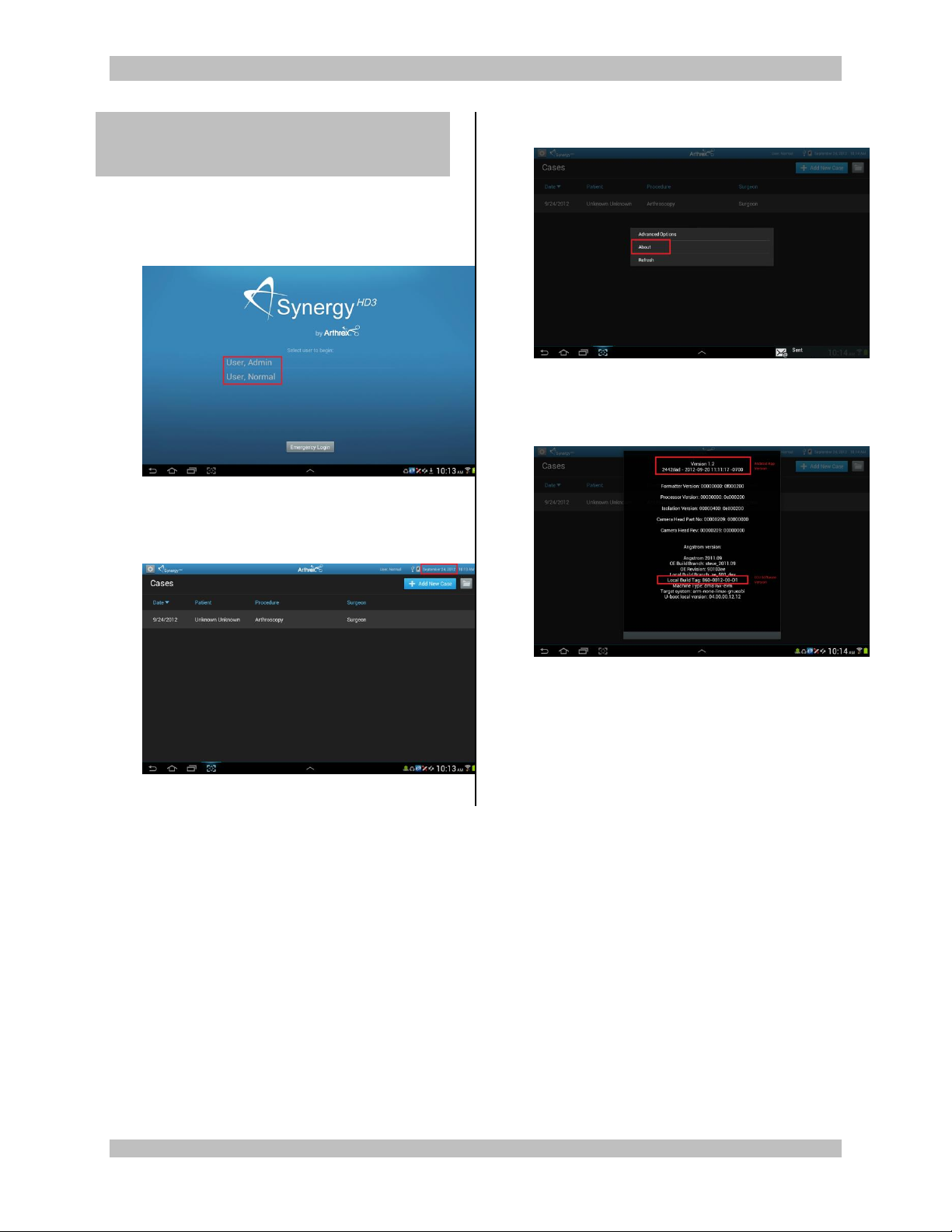
950-0078-00, Rev. A English
8.0 APPENDIX [SW
Version access]
ACCESS to SW Version on Synergy HD3
1. Login to the Android application
Figure 33-Logging on to Android
2. Tap and hold the date field to bring up the
Admin Options
3. Tap About
Figure 35-Tap ABOUT
4. Tablet and CCU software version are
displayed
Figure 34-Tap and Hold DATE FIELD
Figure 36-SW Version Information
950-0078-00 A 67 of 69
Page 68

950-0078-00, Rev. A English
This page intentionally left blank.
950-0078-00 A 68 of 69
Page 69
950-0078-00, Rev. A English
Arthrex GmbH
Erwin-Hielscher-Strasse 9
81249 München, Germany
+49 89 909005-0
Arthrex, Inc.
1370 Creekside Blvd.
Naples, FL 34108, USA
Customer Service
866-267-9138
All rights reserved. Printed in USA
950-0078-00 A 69 of 69
 Loading...