

Page 1
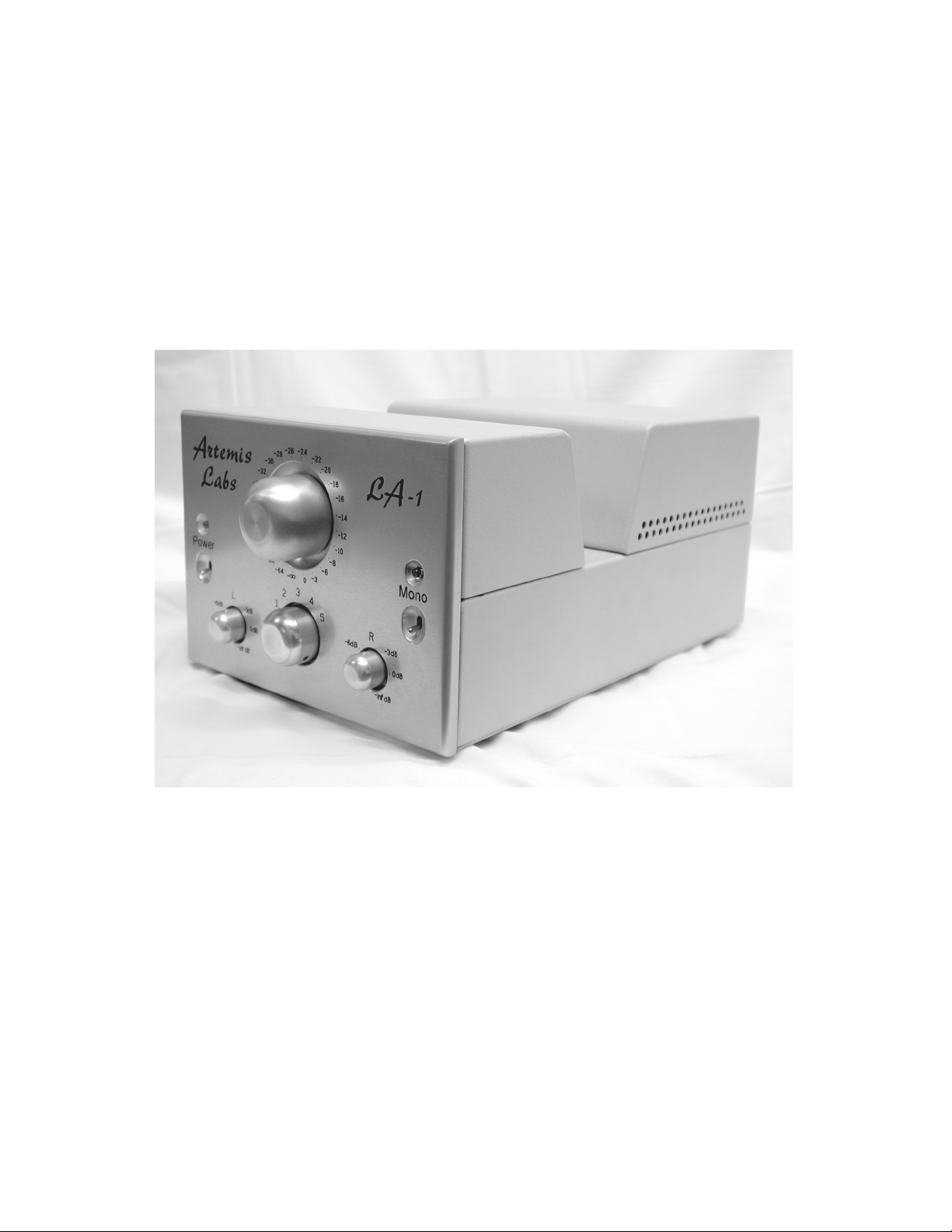
Artemis Labs LA-1
Operating Manual
Page 2
Important Safety Instructions
CA UT IO N
RIS K OF ELEC TRIC SHO CK
DO N O T O PEN
AT TE NT IO N
RISQU E DE CHOC ELECT RIQUE
NE P A S O UVRI R
1. Read these instructions.
2. Keep these instructions.
3. Heed all warnings.
4. Follow all instructions.
5. Do not use this apparatus near water.
6. Clean only with a dry cloth.
7. Do not block any ventilation openings. Install in accordance with the manufacturer’s instructions.
8. Do not install near any heat sources such as radiators, heat registers, stoves, or other apparatus (including amplifiers).
9. Do not defeat the safety purpose of the grounding-type plug. A grounding-type plug has two
blades and a third grounding prong. The third prong is provided for your safety. If the provided
plug does not fit into your outlet, consult an electrician for replacement of the obsolete outlet.
10. Protect the power cord from being walked on or pinched particularly at plugs, convenience
receptacles, and the point where they exit from the apparatus.
11. Only use attachments/accessories specified by the manufacturer.
12. Unplug this apparatus during lightning storms or when unused for long periods of time.
13. Refer all servicing to qualified service personnel. Servicing is required when the apparatus
has been damaged in any way, such as if the power-supply cord or plug is damaged, liquid has
been spilled inside the appliance or it has been exposed to moisture, the appliance does not
operate normally, or has been dropped.
14. WARNING: To reduce the risk of fire or electric shock, do not expose this apparatus to rain
or moisture.
Explanation of Safety Symbols:
CAUTION: To reduce the risk of electric shock, do not remove the covers.
No user-serviceable parts inside.
Refer Servicing to qualified service
personnel.
This symbol is intended to alert the user to the presence of
uninsulated “dangerous voltage” within the product’s enclosure
that may be of sufficient magnitude to constitute a risk of electric shock to persons.
Page 2
This symbol is intended to alert the user to the presence of
important operating and maintenance (servicing) instruction in
the literature accompanying the appliance.
Page 3

INTRODUCTION & SPECIFICATIONS
The Artemis Labs LA-1 Line Amplifier combines the clean, accurate sound of a purist single-triode line
amplifier with the convenience and reliability of a solid, well-built product. Special care is taken with all
parts in the audio path, from the Goldpoint™ stepped attenuator to the Swedish output chokes by Lundahl.
All aspects of the design were done by John Atwood of One Electron™.
The LA-1 is conservatively designed and is built to last for many years. The only maintenance needed is
the occasional replacement of tubes, and even this has been reduced by the use of Cool-Swap™ technology.
Please read this entire user’s manual so that you can understand all the features and get the most from the
LA-1. The Warranty is on a separate card. Read it and send it in to get full warranty coverage.
SPECIFICATIONS:
Maximum Gain (47K load, 1KHz): 12dB +/- 1.5dB
Frequency Response & Distortion
Worst-case Loading (8K ohms, 1000pF):
Worst-case settings (Input Attenuator and Balance both at -6dB):
Frequency Response: < 10Hz – 32KHz +/- 0.5dB
Average settings (Input Attenuator at -16dB, Balance at -1.5dB):
Frequency Response: < 10Hz – 40KHz +/- 0.5dB
THD+N at 1KHz, 2Vrms output: < 0.12%
Average Loading (47K ohms, 250pF):
Worst-case settings (Input Attenuator and Balance both at -6dB):
Frequency Response: < 10Hz – 45KHz +/- 0.5dB
Average settings (Input Attenuator at -16dB, Balance at -1.5dB):
Frequency Response: < 10Hz – 60KHz +/- 0.5dB
THD+N at 1KHz, 2Vrms output: < 0.05%
Maximum output voltage (47K load, 1KHz, 0.5% THD): 40Vrms
Output Noise (grounded input, 47K load, rms detector):
22Hz - 30KHz: < -82dB below 2Vrms output
“A-weighted”: < -85dB below 2Vrms output
Crosstalk
1KHz: < -75dB
20KHz: < -45dB
Effective Output Impedance: approx. 750 ohms (1KHz)
:
:
Input Impedance: 30K to 50K ohms, depending on Input Attenuator and Balance control settings.
Mains Voltage: Wired at factory for one of the following voltages: 100, 110, 120, 220, 230, 240V, 50 to 60Hz.
Power Consumption (rms) : 30 Watts nominal, 38 Watts maximum.
5
Size: 6 ½" (165 mm) Height, 8 ½" (216 mm) Width, 14
Mass: 22 lbs. (10Kg)
Note: These specifications are subject to change at any time.
⁄8 " (371 mm) Depth
Page 3
Page 4
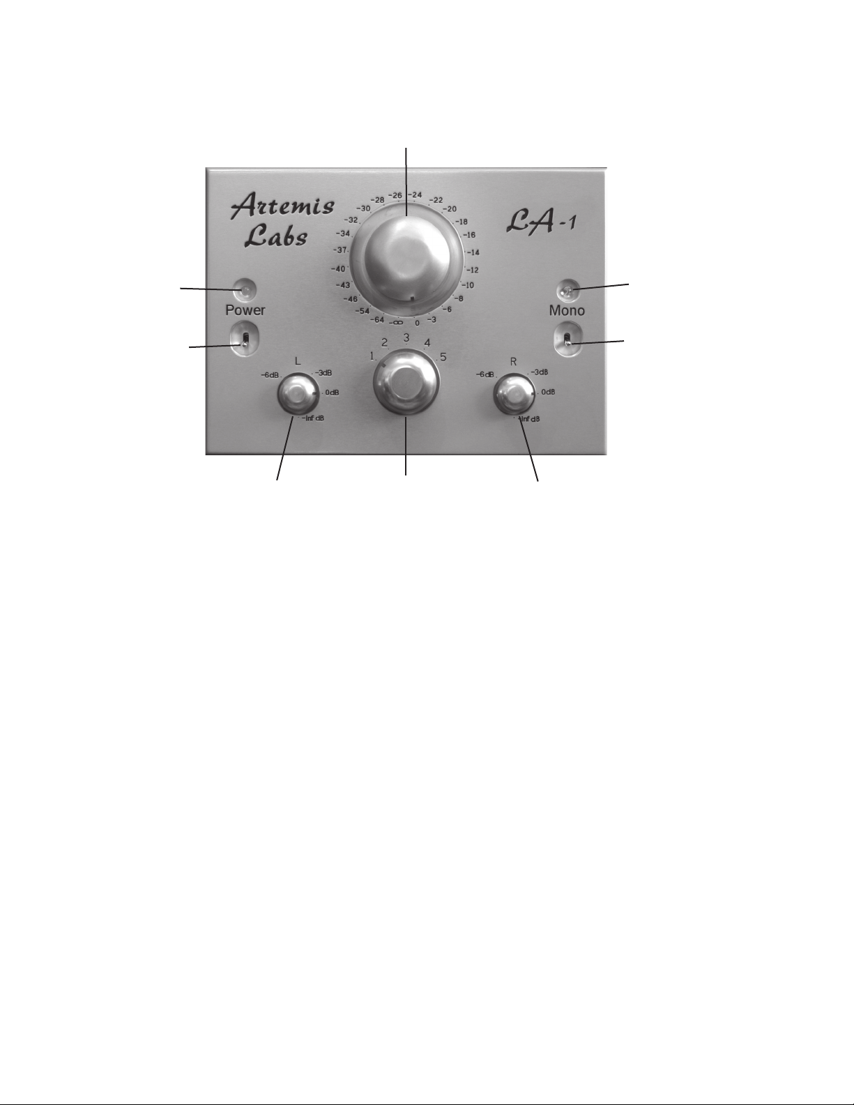
FRONT PANEL
Input Attenuator
Power
Indicator
Power Switch
Left Balance
The Power Switch applies power when flipped up. The Power Indicator will glow red while
the tubes warm up, then after approximately 40 seconds, will glow green. About 4 second after
that a faint click will be heard, indicating the muting relay turning off. The LA-1 is now ready
for use. If the power is removed, even briefly, then restored, the warm-up time delay process
will start over again.
Input
Selector
Right Balance
Mono
Indicator
Mono Switch
Page 4
The Input Attenuator serves as the “Volume Control”. In the full clockwise position, the
output of the LA-1 is at a maximum. Each step counter-clockwise reduces the level to the
amount (in decibels) marked on the front panel. At the full counter-clockwise position, the
output is reduced to zero.
The Input Selector chooses which of the five stereo inputs on the rear panel is used.
The Right Balance
right and left channels, respectively. They should normally be set in their fully clockwise position.
If signal level balancing is required, the louder channel can be reduced by turning its balance
control counter-clockwise.
The Mono Switch, when flipped up, merges the two channels after the Input Attenuator but
before the balance controls. The Mono Indicator glows yellow when the Mono Switch is on.
and Left Balance controls provide an infinite-resolution adjustment of the
Page 5
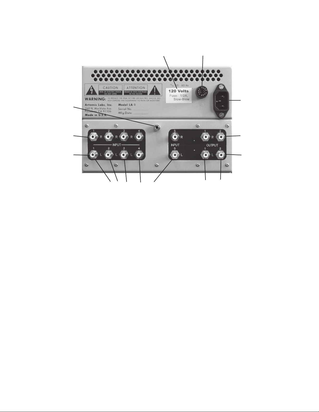
REAR PANEL
Ground
Terminal
Right Inputs
Left Inputs
Voltage Rating
Inputs 1 through 5
Fuse
IEC Power
Connector
Right Outputs
Left Outputs
Outputs 1 and 2
Make sure that the Voltage Rating of your LA-1 matches the power mains voltage at your loca-
tion. The voltage can be changed by internal rewiring, which can be done by Artemis Labs or
by a qualified technician. The Fuse is a 1" x 1¼" “3AG” Slow-blow type. Its value is given on
the Voltage Rating sticker.
A power cord is supplied with each unit. If the mains plug does not match your socket, con
tact your dealer to exchange it for the correct type. The power cord plugs into the IEC Power
Connector. If the power cord is frayed or damaged, replace it with a new one. Use only power
cords that meet the safety standards of your location.
The Ground Terminal is used to connect the chassis of the LA-1 to other equipment in your
system to help minimize hum and noise. Experiment with different connections for the best
results.
Signals are brought into the LA-1 through Inputs 1 through 5. The Right Inputs are on the
top and the Left Inputs are on the bottom. The input number corresponds to the number on
the Input Selector on the front panel.
There are two pairs of outputs: Outputs 1 and 2. These are essentially in parallel, separated by
low-value resistors. This allows the preamp outputs to drive another device in addition to the
power amplifier, such as a digital processor, subwoofer, etc. The Right Outputs are on top and
the Left Outputs are on the bottom.
-
Page 5
Page 6
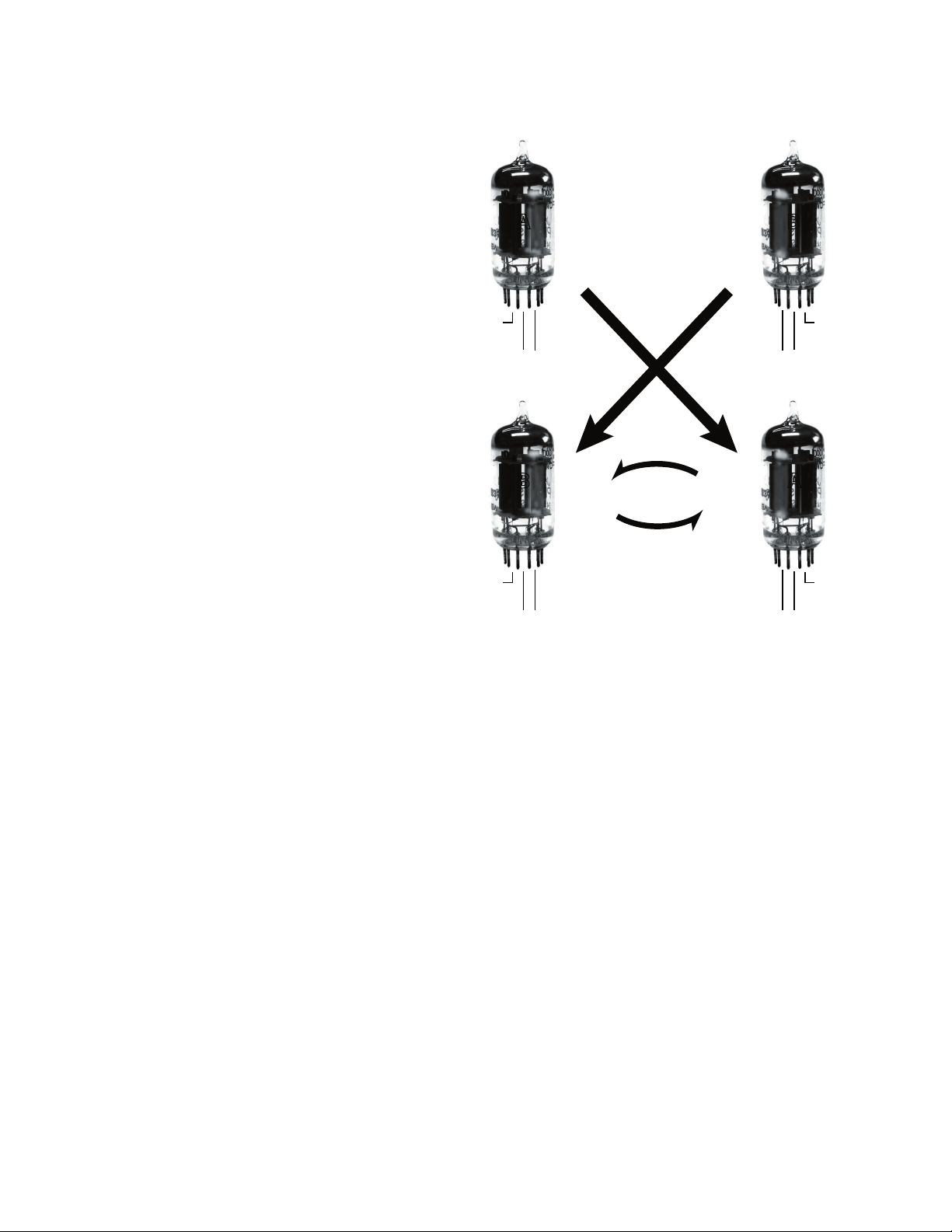
The LA-1 uses Cool-Swap™ technology to let
6 Volts6 Volts
No
Co
nnectio n
No
Connection
A B
B
A
6 Volts6 Volts
No
Co
nnectio n
No
Connection
Cool-
Swap
TM
Left Right
the tubes run cooler and provide a built-in
spare.
Many dual triodes, including the 5687, have
split heaters, allowing them to run from either
6.3V or 12.6V. This heater set-up allows only
one of the two triodes to be heated. In the
Cool-swap configuration, one tube is used
for each channel, each with one half heated.
The right channel uses triode #1 and the left
channel uses triode #2. Since the main failure
mode in modern tubes is cathode wear-out,
the unused triode in each tube is essentially a
spare. By swapping the two tubes, the unused
spare is brought into use. Thus Cool-Swap
effectively doubles tube life, and since only
half the tube is heated, the tube runs cooler,
an important factor in the normally hot-run
ning 5687. A side benefit is reduced cross-talk
between channels, since each channel has its
own tube.
TUBES
One effect of the Cool-Swap technology is that
only one half of each tube will be “lit-up”. This
is normal in the LA-1.
How often you have to swap tubes, or replace
them with new tubes if already swapped,
depends on how you use the LA-1. The
5687WB tubes supplied with the LA-1 should
last several thousand hours of active use. Signs
that the tubes are weak include: less gain than
usual, a “flabby” sound, excess noise, and a
weak reading on a tube tester.
Since the LA-1 uses a soft heater turn-on and
delayed application of high voltage, tube life
time is not degraded by power cycling. Thus,
it is recommended that the LA-1 not be left
on all the time, but only be turned-on when
needed, with perhaps a one-half hour warmup time, if desired.
Tube Types: The tube manufacturer and tube
type will have an effect on the sound of audio
equipment. The LA-1 was designed for the
American 5687 tube, originally developed by Tung-Sol (the
same manufacturer that developed the 5881 and 6550). This
tube is no longer manufactured, but large quantities are still
available as “N.O.S.” (New Old Stock). The 5687 was used in
industrial and military equipment and as a result, nearly all
tubes available are built to higher quality and reliability standards than tubes for consumer equipment. The 5687WA and
5687WB are later versions with tighter control of their characteristics.
Although not identical in characteristics to the 5687, the fol
lowing tubes can also be used in the LA-1: 6900, 7044, 7119,
and E182CC. If you try these, listen carefully to the sound,
and only use the types that sound the best. The LA-1 was
optimized for the 5687, however.
Warning: Do not use any other types of dual triodes. The
pin connections of all other dual triodes are different and
damage to both the tube and the LA-1 will occur if used.
Artemis Labs is not responsible for damage caused by using
incorrect tubes!
-
Page 6
Page 7
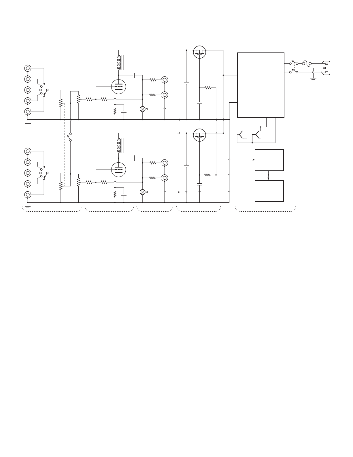
TECHNICAL FEATURES
2
1
3
V1
1/2 56 87
V1
V2
Rig ht
Inp uts
Right
Balan ce
Vo
lume
Input
Selec tor
Mono
Power
Rig ht
Out put s
1
2
4
5
3
2
1
50K
steppe d
atten.
5
4
8
5
4
8
+160V +250V
+250V
+6V
+163V reference
Muting relay
contro l
100K
lin
Lundah l
500H
choke
Power Supp ly
(unre gulat ed)
40 se cond
Delay
4 sec ond
Delay
Lin e v olt age s
ava ila ble :
100 V
,
110V
,
120 V
,
220 V,
230 V
,
240 V
50 or 60H z
Fea tur es:
- E lec tro sta tic all yshi eld ed tra nsf orm er
- H igh -sp eed re cti fie rs
- Hig h-t emp era tur e
(10 5°C ) e lec tro lyt ics
7
9
6
V2
1/2 56 87
Lef t
Inp uts
Left
Balan ce
Lef t
Out put s
1
2
4
5
3
2
1
50K
steppe d
atten.
+160V
100K
lin
Lundah l
500H
choke
Input Co ntrol Gain Muting & Ou tput Low -Gain Regulati on Power Supply & Ti me Delays
LA-1 Line Am plifier
Simplified Schematic
Artemis Labs
Single-triode gain stage with choke loading
Experience has shown that the best audio quality
is achieved with the minimum number of active
devices in the signal path. Each amplifying device
has its own “transfer characteristic” and when
these are multiplied together in a complex design,
the result is an overall transfer characteristic with
high-order distortion products - the worst-sounding ones. The Artemis Labs LA-1 uses a single 5687
medium-mu, low resistance triode as the amplifying device for each channel. The 5687 has excellent
linearity. Its low plate resistance allows it to drive
heavy loads without the use of a cathode follower
stage.
The use of an inductor (choke) load instead of a
conventional plate resistor offers several significant
advantages to the LA-1 design. A good-quality
audio choke is essentially a perfect current source,
allowing the triode to operate into an infiniteresistance load, giving the lowest distortion.
Unlike semiconductor constant-current devices,
an inductor is an energy-storage device. This
allows the plate voltage to swing 100% above the
B+ plate supply voltage, doubling the “head-room”
and allowing a lower B+ supply voltage to be used,
reducing power consumption. This large headroom
permits output of over 40 volts rms before clipping.
The audio chokes used in the LA-1 are made by
Lundahl, a Swedish firm that uses a proprietary core
material that has low distortion. Two windings are
used on a common “C-core”, which reduces pick-up
of hum and noise.
Modest feedback stabilizes gain without hurting
sonic quality
About 4dB of feedback is used across the singletriode amplifying stage. This stabilizes the gain and
makes the frequency response less sensitive to load
ing. The inherent distortion of the 5687 with choke
loading is already very low, so the high-order har
-
monics that can be generated by excessive feedback
are minimal.
Can drive 8K ohm (aggregate) or higher loads
Despite the lack of a cathode-follower output stage,
Page 7
Page 8

the LA-1 can drive loads as low as 8K while still
meeting specifications. This is important when
driving certain solid-state amplifiers or pro audio
equipment which can have input impedances as low
as 10 or 15K ohms.
is hot enough to build-up a protective space charge
around the cathode.) This helps extend tube life. A
muting relay shorts the audio outputs until about
4 seconds after the high voltage is applied. This
allows start-up transients to die away.
High-Quality Conductive-Plastic Balance pots
Since a stepped attenuator allows only discrete level
steps, the balance controls are conductive plastic
pots by Spectrol®, which have a minimum impact
on the sound. By using a separate pot for each channel, the default position (fully clockwise) permits
full gain from the preamp.
Each channel individually voltage regulated
Each channel has its own MOSFET source-follower
low-gain regulator. This insures there is no coupling
between the two channels through the power supply.
The source follower regulator gives good regulation
without the “transistor sound” typical of high gain
regulators using op-amps. Protection resistors and
diodes help prevent burn-out of the MOSFETs.
True voltage regulation minimizes noises and
changed operating conditions due to power line
shifts. Since the impedance of the power supply,
as seen by the amplifier, is low and flat, the bass
response is even and solid.
DC heater supply
A well-filtered DC heater supply helps keep hum
low and allows the use of tubes that would otherwise have too much hum in AC-heated systems.
No troublesome integrated circuits
All time delay and regulation circuits use timeproven, simple discrete semiconductor devices.
Critical audio circuits point-to-point wired with
military-style terminal boards
Conventional fiber-glass PC boards are used for
the power supply and for the rear panel jacks and
switching. All critical circuits in the audio path use
point-to-point wiring on military-style terminal
boards using silver-plated turrets. This technique
minimizes the sonic effects of PC boards and allows
easy component replacement.
High-quality, high temperature capacitors
All electrolytic capacitors are high-quality 105°Crated Panasonic® types for best reliability. All film
capacitors in the signal path are either polypropylene or silvered-mica types.
High-speed rectifiers and electrostatically-shielded
power transformer
Power supply noise is kept to a minimum by the use
of a custom power transformer with electrostatic
shielding between the primary and secondaries.
High speed rectifiers are used for both the plate and
heater supplies.
Delayed high-voltage with delayed muting relay
The high voltage plate supply is applied to the
tubes after a delay of about 40 seconds. This gives
the tubes ample chance to warm-up without the
chance of “cathode stripping” (degradation of the
cathode by bombardment by positive ions before it
Artemis Labs products
are distributed by:
AYDN Vacuum Tube Audio
679 Easy Street, Unit E
Simi Valley, California 93065 USA
Page 8
Available mains voltages (wired at factory): 100V,
110V, 120V, 220V, 230V, 240V, 50 or 60Hz
Virtually all the power systems of the world can be
accommodated by the LA-1 transformer connections. These are set at the factory or can be re-wired
by a qualified technician.
www.aydn.com
Tel: +1 818 216-7882
email: [email protected]
rev 1.0 11/04
 Loading...