

Page 1
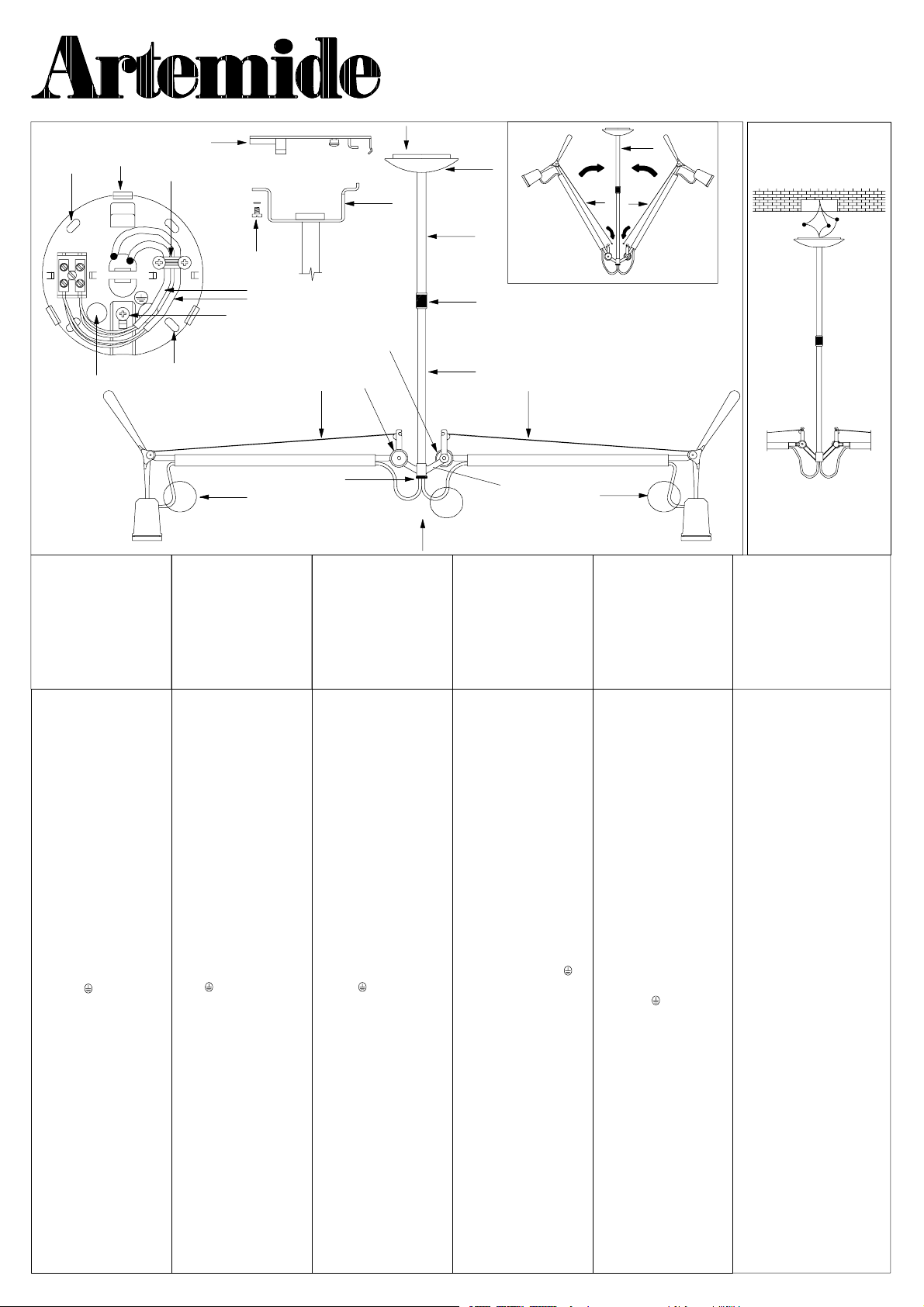
TOLOMEO SOSPENSIONE DIFFUSO RE
CL I - - IP 20
Design: Michele De Lucchi - - Giancarlo Fassina
H
F
G
Avvertenze:
Primadiognioperazione
sull’apparecchio disinserire la
tensione di rete.
Attenzione:
Usareesclusivamentelelampadine del tipoe potenzaindicateneidatiditarga.
M
F
N
L
H
Z
Avis:
Déconnecter la tension de
réseau avant toute opération
sur l’appareil.
Attention:
Employer exsclusivement les
ampoules du type et de la
puissance indiquée sur la plaque de l ’appa reil.
Q
F
R
S
S
P
Z
Note:
Prior to any work on the fixture
always switch off the mains.
Attention:
Onlyusebulbsofthetypeand
wattage indicated on the rating
plate.
E
B
A
C
OO
D
Vorsicht:
Vor jedem Eingriff an dem
Gerät die Netzspannung unterbrechen.
Achtung:
Ausschließlich Lampen verwenden, die dem auf dem a uf
dem Geräteschild angegebenen Typ und Wert entsprechen.
B
O
O
Z
Advertencia:
Desconectar la tensión de red
antes de cualquier operación
sobre el a parado
Atención:
Utilizar exclusivamente las
bombillas del tipo y potencia
indicada en la placa del aparado.
Only for
USA--CANADA
Note:
Prior to any work on the fixture always
switch off the mains.
Avis:
Déconnecter la tension de réseau
avant toute opération sur l’appareil.
Istruzioni di montaggio.
Svitare completamente la
ghiera A. Tenendo ferma con
una mano l’asta B avvitare la
prolunga C sullo snodo D.
Avvitare la ghiera P. Aggan-
ciare i cavetti in acciaio O allo
snodo D. Per agevolare questa operazione si consiglia di
avvicinare i due bracci all’asta
B come descritto in figura.
Separare il coprifondello E dal
fondello F con l’aiuto di un
cacciavite. Far passare i cavi
provenienti dal soffitto nel foro
G e fissare il fondello F
mediantele asole H.Svitarela
vite Q per separare la squadretta R dal fondello F.Ese-
guire i collegamenti elettrici
all’apposito morsetto collegandoilcavodimessaaterra
alla vite L contrassegnata dal
simbolo . Ri montare la
squadretta R ed avvitare la
vite Q. Regolare l’altezza e la
direzione della lampada svitando la ghiera A. Se necessario, allentare il pressacavo M
edaccorciareicavidialimentazione N. Attenzione:
lasciare comunque una lunghezza di cavi sufficiente per
poter muovere la lampada in
tutte le sue posizioni (le zone
indicate con la lettera Z
devono avere una certa
abbondanza di cavo). Riposizionare il coprifondello E.
Agire sulle ghiere S per
aumentare o diminuire la rigidità dei movimenti dell’apparecchio.
Instructions de
montage.
Dévisser complètement le
collier de serrage A.Entenant bien ferme la tige B par la
main visser la rallonge C sur
l’articulation D. Visser le collier de serrage P. Accrocher
lespetitscâblesd’acierO à
l’articulation D. Pour faciliter
cette opération on conseille
d’approcher les deux bras à
la tige B comme décrit dans la
figure. Séparer le couvre- culot F avec un tournevis.
Fairepasser les câbles provenants du plafond dans le trou
G et fixer le culot F par les
boutonnières H. Dévisser la
vis Q pour séparer l’équerreR
du culot F.Brancherles
câbles à la borne en connectantlecâbledemiseàlaterre
àlavisL marquée par le symbole . Remonter l’équerre
R et visser la vis Q. Dévisser le
collier de serrage A et régler
la hauteuret la direction de la
lampe. Si on nécessite, desserrer la bloque- -câbles M et
raccourcir les câbles d’alimentati on N. Attention:
laisser, en tout cas, une longueurdecâblessuffisantede
manière à pouvoir bouger la
lampe dans toutes ses positions (les zones indiquées par
la lettre Z doivent avoir une
certaine abondance de
câble).Mettredenouveaule
couvre- -culot E.Agirsurles
douilles S pour rendre les
mouvements de l’appareil
plus ou moins rigides.
Assembly instructions.
Completely unscrew the
locking ring A. Keeping the
rod B with a hand screw the
extensioncable C on the joint
D.ScrewthelockingringP.
Couple up steel cables O to
joint D. In order to facilitate
this operation i t is advisable
to bring the two arms near rod
B as described in figure. Separate bottom plate cover E
from bottom plate F with a
screwdriver. Pass cables proceding from ceiling through
hole G and fix bottom plate F
by loops H. Untighten the
screw Q to separate the
square R from the bottom
plate F. Carry out electrical
connections to terminal strip
by connecting earthing cable
to screw L marked with the
symbol . Reassemble the
square R and tighten the
screw Q. Unscrew locking
ring A and adjust lamp height
and direction. If necessary,
loose cable- -clamp M and
shorten feeding cables N.
Attention: keep a cable
length enough to move the
lamp in all its positions (the
zones with the letter Z should
have a certain cable extension). Reposition bottom
plate cover E.Adjustthelock
rings S to increase or decrease the device movement
stiffness.
Aufbaueinleitung
Den Ring A ganz lockern. Die
Stange B mit der Hand festhalten und die Verlängerung C auf
dem Gelenk D festschrauben.
Den Ring P anziehen. Die
Stahlkabel O an das Gelenk D
anhaken. Um diese Aktion zu
erleichtern, rat man die zwei
Arme an die Stange B nähern,
wie es im Bild angezeigen ist.
Das B asisstück F von seinem
Schutz E mittels eines Schraubenziehers trennen. Die aus
der Decke kommenden Kabel
in die BohrungG einführen und
das Basisstück F durch die
Ösen H befestigen. Die
Schraube Q lockern, um die
Halterung R vom Boden F zu
trennen. Die elektrischen
Schaltungen an die entsprechende Klemme vornehmen,
indem man da s Erdungskabel
an die Schraube L verbindet,
die mit dem Symbol
angezeichnete ist. Die Halterung R wieder einbauen und die
Schraube Q befestigen. Die
Höhe und die Richtung der
Lampe durch Auf schrauben
der Zwinge A einstellen. Wenn
nötig, die kabelpresse M lösen
und die Speisekabel N künzen.
Achtung: immer lassen eine
genügende Länge der Kabel,
so ka nn man die Lampe in alle
ihre Stellungen bewegen (die
Zonen, die mit dem Buchstabe
Z angezeichneten sind, mus-
sen einen gewissen Überfluß
anKabel haben).Die Dekung E
das Basisstükes F wieder an
ihre Stelle setzen. Das
Leuchtmittel anschrauben. Auf die Nutmuttern
S wirken, um die Steifigkeit der Bewegungen
desGerätszuerhöhen
oder zu vermindern.
Instrucci one s para
el montaje.
Destornillar completamente la
virola A.Mantenerfirmecon
una mano la varilla B yatornillar la prolongación C sobre la
articulación D. Atornillar la
virola P. Enganchar los cables
de acero O a la “articulación
D”. Para volver más fácil esta
operaciónse aconseja acercar
los dos brazos a la varilla B
como muestra la figura. Separar el cubre- -placa E de la
placa F conundestornillador.
Hacer pasar los cables procedentes del techo en el orificio
G y fijar la placa de fijación F
mediante los ojales H.Destornillar el tornillo Q para separar
la escuadretaR de la pla ca de
fijación F. Conectar los cables
al borne conectando el cable
de puesta a la tierra al tornillo
L contramarcada con el
símbolo . Volver a
montar la escuadreta R yatornillar el tornillo Q. Destornillar
la virola A y regular la altura y
la dirección de la lámpara. Si
necesita, aflojar el sujeta- cables M y acortar los cables
alimentadoresN. Atención:de
cualquier modo dejar un trozo
de cables suficiente para
poder mover la lámpara en
todas sus posiciones (en las
zonas indicadas con la letra Z
debe queda r una cantidad de
cable abundante). Volver a
posicionar el cubre- -placa de
fijaciónE. Actuar sobre las
tuercas anulares S para
aumentar o reducir la
rigidez de los
movimientos del
aparato.
Instructionsfor mounting to wall
box:
Completely unscrew the locking ring A.
Keeping t he rod B with a hand screw the
extension cable C on the joint D.Screw
the locking ring P. Couple up steel cables
O to joint D. In order to facilitate this
operation it is advisable to bring the two
arms near rod B as described in figure.
Separate bottom plate cover E from bottom plate F wi th a screwdriver. Make the
electrical connections by connecting the
WHITEwire from the fixture to the WHITE
wire from the wall box and the fixture
BLACK wi re to the BLACK wi re. Also connect the GREEN wire f rom plate to the
system ground conductor. Fix rose to
wall box. Unscrew locki ng ring A and
adjust lamp height and direction. If
necessary, loose cable- -clamp M and
shorten feedin g cables N. Attention:
keep a cable len gth enou gh to move the
lamp in all its positions (the zones with
the letter Z should have a cert ain cable
extension). Reposition bottom plate
cover E . Insert bulbs.
Instructions de montage sur la
prise à mur
Dévisser c omplètemen t le collier de serrageA. EntenantbienfermelatigeBpar
la main visser la rallongeC sur l’artic ulation D. Visser le col lier de serrage P.
Accrocher les petits câbles d’acier O au
rotule D. Pour f aciliter cette opération on
conseille d’approcher les deux bras à l a
tige B comme décrit dans la fi gure.Séparer l e couvre- -culot F avec un tournevis. Connecter le câble BLANC de l’installation au câble B LANC de la prise à mu r
el le câbleNOIR de l’installationau câble
NOIR. Connecter en outre le câble VERT
de la plaque au conducteur de terre du
système.Fi xer la rosace à la pr ise à mur.
Dévisser l e col lier de serrage A et régler
la hauteur et la direction de la lampe. Si
on nécessite, desserrer la bloque- câbles M et raccourcir les câbles d’alimentation N. Attention: lai sser, en tout
cas, unelongueurdecâbles suffisante de
manière à pouvoi r bouger la lampe dans
toutesses positions (les zones indiquées
par la lettre Z doivent avoir une certaine
abondancedecâble).Mettre denouveau
le couvre- -culot E. Insér er les ampoules.
Page 2

Per il montaggio del diffusore T svitare la ghiera V , posizionare il diffusore T e riavvitare la ghiera V. Avvitare
la lampadina. Attenzione: per la pulizia di questo diffusore utilizzare esclusivamente una spazzola. In
nessun caso utilizzare acqua o detergenti.
Pour le montage du diffuseur T de sserrer la douille V,positionner le diffuseur T et serrer de nouveau la douille
V. Serrer la lampe.Attention: pour le nettoyage de ce diffuseur, seulement utiliser une brosse. En aucun
cas n’utiliser de l’eau ou de détergents.
T
V
Lampadine:
2x150W IAA E27
2x150W IAG E27
2x150W HSG E27
To install the diffuser T, loosen the lock ring V. Install the diffuser T and re- -tighten the lock ring V.Tighten
the bulb. Note: use a brush to clean the diffuser. Do not use water or detergents.
Fürdie Montage des DiffusorsT die Nutmutter V abschrauben, den Diffusor T positionieren und die Nutmutter V wieder anschrauben. Achtung: für die Reinigung von diesem Diffusor ausschließlich eine Bürste
verwenden. In keinem Fall Wasser oder Reinigungsmittel verwenden.
Para montar el difusor T desenroscar la tuerca anular V, colocar el difusor T y enroscar de nuevo la tuerca
anular V. Enroscar la bombilla. Atención: para limpiar esta pantalla usar exclusivamente un cepillo.
Bajo ninguna circunstancia usar agua o detergentes.
Ampoules:
2x150W IAA E27
2x150W IAG E27
2x150W HSG E27
Bulbs:
2x150W IAA E27
2x150W IAG E27
2x150W HSG E27
For USA and
Canada only:
2x150W
type A—G—T10
Glühlampen:
2x150W IAA E27
2x150W IAG E27
2x150W HSG E27
Bombillas:
2x150W IAA E27
2x150W IAG E27
2x150W HSG E27
E26
Il simbolo indica l’idoneitá degli apparecchi al montaggio diretto su superficinor-
F
ARTEMIDE s.p.a. non si assume alcuna responsabilità per prodotti modificati senza preventiva autorizzazione.
ARTEMIDE spa décline toute responsabilité pour les produits modifiés sans autorisation préalable.
ARTEMIDE spa not shoulder any responsibilities should products be modified without prior authorisation.
ARTEMIDE s.p.a. nimmt keine Verantwortung für ohne Vorgenehmigung geänderte Produkte an.
ARTEMIDE spa no se asume ninguna responsabilidad ante productos modificados sin autorización.
Attenzione: La sicurezza elettrica di questo apparecchio è garantita con l’uso appropriato di queste istruzioni. Pertanto è necessario conservarle.
Attention: La securitè de l’appareil n’est garantie que si les instructions sont convenablement suivies.Il est donc necessaire de les conserver.
Attention: This equipment is guaranteed only when used as indicated in these instructions. Therefore they should be kept for future reference.
Achtung: Die Sicherheit der Leuchte wird nur bei sachgerechtem Gebrauch gemäss Anweisungen gewährleistet. Bitte bewahren Sie diese sorgfältig auf.
Atencion: La seguridad del aparato está garantizada solo con el uso apropriado de las instrucciones. Por lo tanto es necesario conservarlas.
malmente infiammabili. Gli apparecchi privi del suddetto simbolo sono ido nei ad
essere installati esclusivamente su superfici non combustibili.
Le symbole indique que les appareils sont indiqués pour être montés directement
sur des surfacesnormalement i nflammables.Les appareils ne portantpas ce symbole peuvent être montés exsclusivement sur des surfaces non combustibles.
The symbol indicates the suitabily of fixtures to be mounted directly on normaly
inflammable surfaces. Fixtures without the above symbol are only suitable for
installation on non- -inflammable surfaces.
DasSymbol zeigt an, ob die Geräte dazu geeignet sind,auf normalentflammbaren
Oberflächen angebracht zu werden. Geräte ohne dieses Symbol sind ausschließlich dazu geeignet, auf nicht entflammbaren Oberflächen angebracht zu
werden.
El símbolo indica que los aparatos son aptos para ser montados directamente
sobre superficies normalmente inflamables. Los aparatos desprovistos de dicho
símbolo pueden ser instalados exsclusivamente sobre superficies no combustibles.
Tuttii prodotti ARTEMIDE che rientrano nell’ambito di applicazione della direttiva europea
bassa tensione B .T. 73/23 e successiva modifica 93/68, soddisfano ai requisiti richiesti e
recano la marcatura ” ”.
To u s l e s pr o d u i t s ARTEMIDE appartenants au champ d’application de la directive
européennebasse tension B.T. 73/23 et modification sucessive93/ 68, remplissentles conditions prévues et portent le marquage ” ”.
All ARTEMIDE products falling withinthe range of application of the European low vo l tage
directive B.T. 73/23 and subsequent amendment 93/68, meet the required specifications
and bear ” ” labelling.
Alle Produkte von ARTEMIDE, die unter das Anwendungsgebiet der europäischen Richtlinie der Niederspannung B.T.73/23 und nachfolgende Änderung 93/68 fallen, entsprechen
den erforderlichen Eigenschaften und tragen das ” ”- -Kennzeichen.
Todos los productos ARTEMIDE que pertenencen al ámbito de aplicación de la di rectiva
europea baja tensión B.T. 73/ 23 i modificación 93/68, cumplen los requisitos correspondientes y ll e va n el marcado ” ”.
In caso di reclamo citare il numero
En cas de réclamation, veuillez citer le numéro
In case of complaint, please quote number
Bei jeder Reklamation geben Sie, bitte folgende Nummer an
En caso de reclamación indicar el número
cod. Y503001050
via Bergamo, 18- -20010 Pregnana Milanese (Milano)- -ITALIA
tel:93.51.81- -(a ricerca automatica)
telefax 02/93.59.02.54- -93.59.04.96
sito internet http://www.ARTEMIDE.COM
codice fiscale e partita I.V.A. 00846890150
 Loading...