

Artema Cardio-Aid 200 Service manual
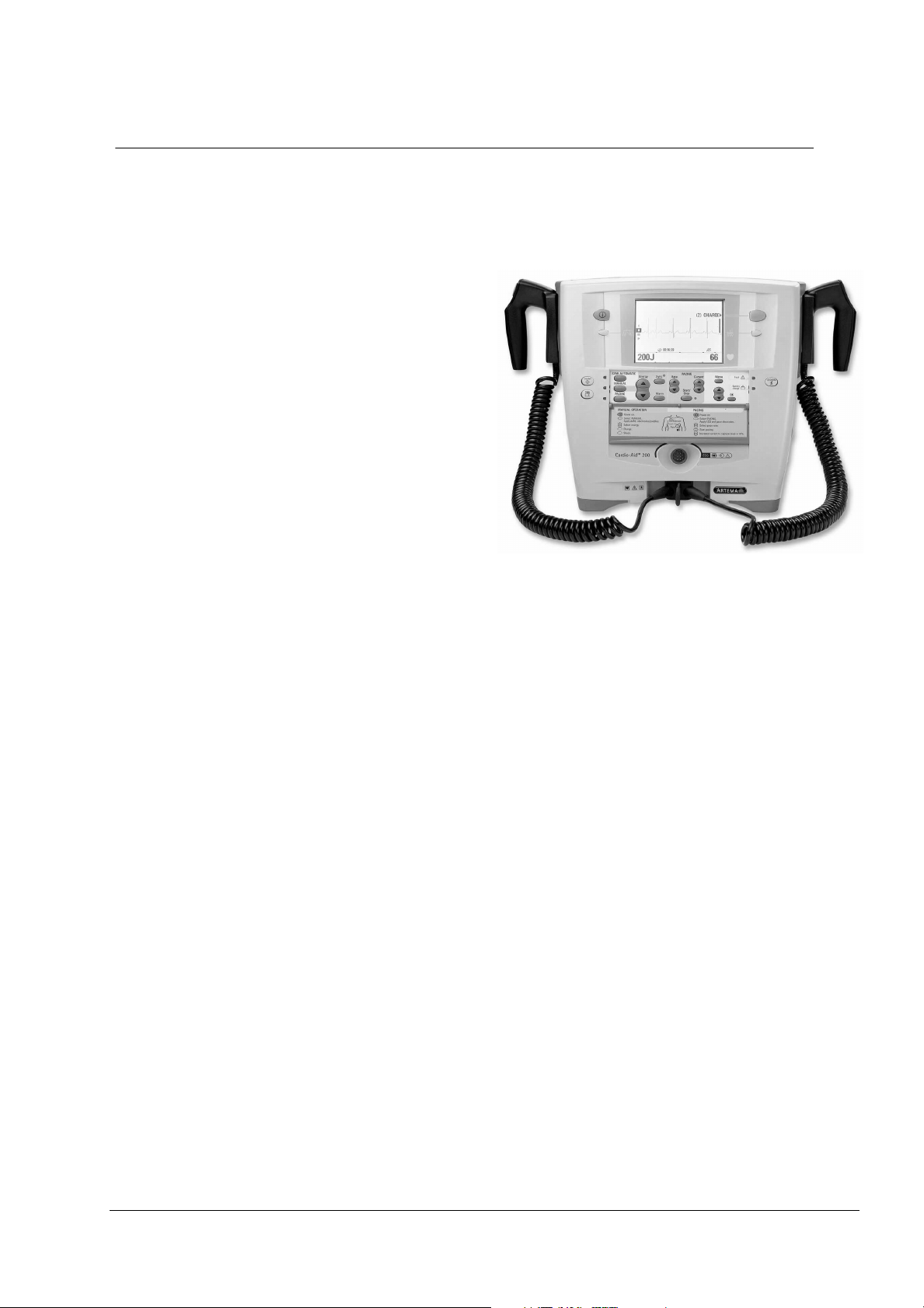
Cardio-Aid® 200
Service Manual
Contents:
Introduction.
Logbook. 2
Technical description. 3
Interconnections. 4
Dismantling & re-assembly. 5
Trouble shooting. 6
Verification and Test. 7
Maintenance. 8
Defi program. 9
1
Spare parts. 10
Service News. 11
Index. 12

Artema MEC. A/S CA200, Service manual No. 95900-B Page 2

Table of contents
1. Introduction. . . . . . . . . . . . . . . . . . . . . . . . . . . . 1
1.1. Service policy. . . . . . . . . . . . . . . . . . . . . . . . . . . . . . . . . . . . . . . . . . . . . . . . . . . . . . . .2
1.2. The product. . . . . . . . . . . . . . . . . . . . . . . . . . . . . . . . . . . . . . . . . . . . . . . . . . . . . . . . . .3
1.2.1. Philosophy of the Cardio-Aid‚. . . . . . . . . . . . . . . . . . . . . . . . . . . . . . . . . . . .3
1.2.1.1 The first responder. . . . . . . . . . . . . . . . . . . . . . . . . . . . . . . . . . . . . . . .3
1.2.1.2 The experienced . . . . . . . . . . . . . . . . . . . . . . . . . . . . . . . . . . . . . . . . . .3
1.2.2. Semi automatic mode. . . . . . . . . . . . . . . . . . . . . . . . . . . . . . . . . . . . . . . . . . .4
1.2.3. Manual mode. . . . . . . . . . . . . . . . . . . . . . . . . . . . . . . . . . . . . . . . . . . . . . . . . .4
1.2.4. Pacer. . . . . . . . . . . . . . . . . . . . . . . . . . . . . . . . . . . . . . . . . . . . . . . . . . . . . . . . .4
1.2.5. Test mode. . . . . . . . . . . . . . . . . . . . . . . . . . . . . . . . . . . . . . . . . . . . . . . . . . . . .4
1.2.6. Service and Configuration menus. . . . . . . . . . . . . . . . . . . . . . . . . . . . . . . . .5
1.2.7. General user interface principle. . . . . . . . . . . . . . . . . . . . . . . . . . . . . . . . . . .5
1.2.8. The Cardio-Aid‚ design. . . . . . . . . . . . . . . . . . . . . . . . . . . . . . . . . . . . . . . . . .5
1.2.9. Memory card. . . . . . . . . . . . . . . . . . . . . . . . . . . . . . . . . . . . . . . . . . . . . . . . . .6
1.2.10. Printer (optional). . . . . . . . . . . . . . . . . . . . . . . . . . . . . . . . . . . . . . . . . . . . . .6
1.2.11. Pads. . . . . . . . . . . . . . . . . . . . . . . . . . . . . . . . . . . . . . . . . . . . . . . . . . . . . . . .7
1.2.12. External paddles. . . . . . . . . . . . . . . . . . . . . . . . . . . . . . . . . . . . . . . . . . . . . .7
1.2.13. Internal paddles. . . . . . . . . . . . . . . . . . . . . . . . . . . . . . . . . . . . . . . . . . . . . . .8
1.3. Installation. . . . . . . . . . . . . . . . . . . . . . . . . . . . . . . . . . . . . . . . . . . . . . . . . . . . . . . . . .8
1.3.1. Trolley mount. . . . . . . . . . . . . . . . . . . . . . . . . . . . . . . . . . . . . . . . . . . . . . . . . .8
1.3.2. Wall mount. . . . . . . . . . . . . . . . . . . . . . . . . . . . . . . . . . . . . . . . . . . . . . . . . . .9
1.3.3. Bed mount. . . . . . . . . . . . . . . . . . . . . . . . . . . . . . . . . . . . . . . . . . . . . . . . . . .10
1.3.4. Bag. . . . . . . . . . . . . . . . . . . . . . . . . . . . . . . . . . . . . . . . . . . . . . . . . . . . . . . . .10
2. Logbook. . . . . . . . . . . . . . . . . . . . . . . . . . . . . . 11
2.1. Logbook. . . . . . . . . . . . . . . . . . . . . . . . . . . . . . . . . . . . . . . . . . . . . . . . . . . . . . . . . . . .11
2.2. Goods to repair. . . . . . . . . . . . . . . . . . . . . . . . . . . . . . . . . . . . . . . . . . . . . . . . . . . . . .12
2.3. Complaint form. . . . . . . . . . . . . . . . . . . . . . . . . . . . . . . . . . . . . . . . . . . . . . . . . . . . .13
3. Technical description.. . . . . . . . . . . . . . . . . . . 15
3.1. Block description. . . . . . . . . . . . . . . . . . . . . . . . . . . . . . . . . . . . . . . . . . . . . . . . . . . .16
3.1.1. Power management. . . . . . . . . . . . . . . . . . . . . . . . . . . . . . . . . . . . . . . . . . .17
3.1.1.1 Power Supply board. . . . . . . . . . . . . . . . . . . . . . . . . . . . . . . . . . . . . .17
3.1.1.2 Battery-pack. . . . . . . . . . . . . . . . . . . . . . . . . . . . . . . . . . . . . . . . . . . .18
3.1.2. Defi board. . . . . . . . . . . . . . . . . . . . . . . . . . . . . . . . . . . . . . . . . . . . . . . . . . .18
3.1.3. Multi output converter. . . . . . . . . . . . . . . . . . . . . . . . . . . . . . . . . . . . . . . . .19
3.1.4. Battery fast-charge and energy monitoring. . . . . . . . . . . . . . . . . . . . . . . .19
3.1.5. Defi Controller and safety logic. . . . . . . . . . . . . . . . . . . . . . . . . . . . . . . . . .19
3.1.6. Shock gate. . . . . . . . . . . . . . . . . . . . . . . . . . . . . . . . . . . . . . . . . . . . . . . . . . .19
3.1.7. High Voltage Generator. . . . . . . . . . . . . . . . . . . . . . . . . . . . . . . . . . . . . . . .20
3.1.8. ECG interface. . . . . . . . . . . . . . . . . . . . . . . . . . . . . . . . . . . . . . . . . . . . . . . . .20
3.1.9. Processor board. . . . . . . . . . . . . . . . . . . . . . . . . . . . . . . . . . . . . . . . . . . . . . .21
3.1.10. Flash PROM and RAM. . . . . . . . . . . . . . . . . . . . . . . . . . . . . . . . . . . . . . . . .21
3.1.11. Controller for Liquid Crystal Display. . . . . . . . . . . . . . . . . . . . . . . . . . . . .21
3.1.12. Real Time Clock. . . . . . . . . . . . . . . . . . . . . . . . . . . . . . . . . . . . . . . . . . . . . .22
3.1.13. Voice and sound generator. . . . . . . . . . . . . . . . . . . . . . . . . . . . . . . . . . . . .22
3.1.14. Watchdog. . . . . . . . . . . . . . . . . . . . . . . . . . . . . . . . . . . . . . . . . . . . . . . . . .22
Artema MEC. A/S CA200, Service manual No. 95900-B, Page 1

3.1.15. Defi controller interface. . . . . . . . . . . . . . . . . . . . . . . . . . . . . . . . . . . . . . 22
3.1.16. ECG and Printer interface. . . . . . . . . . . . . . . . . . . . . . . . . . . . . . . . . . . . . 22
3.1.17. PCMCIA interface. . . . . . . . . . . . . . . . . . . . . . . . . . . . . . . . . . . . . . . . . . . 22
3.1.18. Keyboard interface. . . . . . . . . . . . . . . . . . . . . . . . . . . . . . . . . . . . . . . . . . 23
3.2. Defi Test board. . . . . . . . . . . . . . . . . . . . . . . . . . . . . . . . . . . . . . . . . . . . . . . . . . . . . 23
3.3. The ECG amplifiers. . . . . . . . . . . . . . . . . . . . . . . . . . . . . . . . . . . . . . . . . . . . . . . . . . 23
3.3.1. Cable ECG board. . . . . . . . . . . . . . . . . . . . . . . . . . . . . . . . . . . . . . . . . . . . . 23
3.3.2. Paddle ECG board. . . . . . . . . . . . . . . . . . . . . . . . . . . . . . . . . . . . . . . . . . . . 23
3.4. Printer (optional). . . . . . . . . . . . . . . . . . . . . . . . . . . . . . . . . . . . . . . . . . . . . . . . . . . 24
3.5. Pacer (optional). . . . . . . . . . . . . . . . . . . . . . . . . . . . . . . . . . . . . . . . . . . . . . . . . . . . 24
3.5.1. Boost regulator. . . . . . . . . . . . . . . . . . . . . . . . . . . . . . . . . . . . . . . . . . . . . . 24
3.5.2. Pace generator. . . . . . . . . . . . . . . . . . . . . . . . . . . . . . . . . . . . . . . . . . . . . . . 24
3.5.3. Pace security system. . . . . . . . . . . . . . . . . . . . . . . . . . . . . . . . . . . . . . . . . . 25
4. Interconnections.. . . . . . . . . . . . . . . . . . . . . . . 27
4.1. Interconnections. . . . . . . . . . . . . . . . . . . . . . . . . . . . . . . . . . . . . . . . . . . . . . . . . . . . 27
4.2. External connectors. . . . . . . . . . . . . . . . . . . . . . . . . . . . . . . . . . . . . . . . . . . . . . . . . 28
4.2.1. Signal type definition. . . . . . . . . . . . . . . . . . . . . . . . . . . . . . . . . . . . . . . . . 28
4.2.2. Front connectors. . . . . . . . . . . . . . . . . . . . . . . . . . . . . . . . . . . . . . . . . . . . . 28
4.2.2.1 ECG connector. . . . . . . . . . . . . . . . . . . . . . . . . . . . . . . . . . . . . . . . . . 29
4.2.2.2 HV socket. . . . . . . . . . . . . . . . . . . . . . . . . . . . . . . . . . . . . . . . . . . . . . 30
4.2.3. PCMCIA connector. . . . . . . . . . . . . . . . . . . . . . . . . . . . . . . . . . . . . . . . . . . 30
4.2.3.1 RS 232 card serial link to PC. . . . . . . . . . . . . . . . . . . . . . . . . . . . . . 31
4.2.3.2 Requirements: . . . . . . . . . . . . . . . . . . . . . . . . . . . . . . . . . . . . . . . . . 31
4.3. Internal connectors. . . . . . . . . . . . . . . . . . . . . . . . . . . . . . . . . . . . . . . . . . . . . . . . . 32
4.3.1. Defi board connectors. . . . . . . . . . . . . . . . . . . . . . . . . . . . . . . . . . . . . . . . . 32
4.3.1.1 J4001 – POWER input from mains supply. . . . . . . . . . . . . . . . . . . 32
4.3.1.2 J4002 – HIGH VOLTAGE - output to HV relay. . . . . . . . . . . . . . . . 33
4.3.1.3 J4003 - HIGH VOLTAGE RELAY-coil. . . . . . . . . . . . . . . . . . . . . . . . 33
4.3.1.4 J4005 – VSYS RTN. . . . . . . . . . . . . . . . . . . . . . . . . . . . . . . . . . . . . . 33
4.3.1.5 J4006 – HV - shield. . . . . . . . . . . . . . . . . . . . . . . . . . . . . . . . . . . . . 33
4.3.1.6 J4100 - Communication and supply for the Processor board. . . . 33
4.3.1.7 J4101 – Paddles control. . . . . . . . . . . . . . . . . . . . . . . . . . . . . . . . . . 35
4.3.1.8 J4102 – Defi HV-test and supply. . . . . . . . . . . . . . . . . . . . . . . . . . . 35
4.3.1.9 J4103 – Communication for CABLE ECG board. . . . . . . . . . . . . . . 35
4.3.1.10 J4104 – Communication and supply for PACER board (Option). 35
4.3.1.11 J4107 – Supply for the PADDLE ECG board. . . . . . . . . . . . . . . . . 36
4.3.1.12 J4108 – Supply for the CABLE ECG board. . . . . . . . . . . . . . . . . . 37
4.3.1.13 J4109 – Communication for the PADDLE ECG board. . . . . . . . . 37
4.3.1.14 J4110 – Paddle ECG signals to the PADDLE ECG board. . . . . . . . 37
4.3.1.15 J4111 – Patient impedance signals for the PADDLE ECG board. 37
4.3.1.16 J4112 – ECG Apex paddles. . . . . . . . . . . . . . . . . . . . . . . . . . . . . . 37
4.3.1.17 J4114 – ECG Sternum paddles. . . . . . . . . . . . . . . . . . . . . . . . . . . 38
4.3.1.18 J4405 – Battery power input and printer supply. . . . . . . . . . . . . 38
4.3.1.19 E4101, E4102, E4103, E4104 – EMC shield. . . . . . . . . . . . . . . . . 38
4.3.2. ECG connector board. . . . . . . . . . . . . . . . . . . . . . . . . . . . . . . . . . . . . . . . . . 38
4.3.2.1 J801 – ECG Input. . . . . . . . . . . . . . . . . . . . . . . . . . . . . . . . . . . . . . . 38
4.3.2.2 E801 – ECG Input. . . . . . . . . . . . . . . . . . . . . . . . . . . . . . . . . . . . . . . 39
4.3.2.3 J802 – ECG signal for Cable ECG board. . . . . . . . . . . . . . . . . . . . . 39
4.3.3. Printer board connectors. . . . . . . . . . . . . . . . . . . . . . . . . . . . . . . . . . . . . . 39
4.3.3.1 J701 – Printer, data bus and supply. . . . . . . . . . . . . . . . . . . . . . . . 40
4.3.4. Processor board connectors. . . . . . . . . . . . . . . . . . . . . . . . . . . . . . . . . . . . 41
4.3.4.1 J3004 – LCD, Data for display. . . . . . . . . . . . . . . . . . . . . . . . . . . . . 43
Page 2, Artema MEC. A/S CA200, Service manual No. 95900-B

4.3.4.2 J3005 - LCD CCFL, backlight power. . . . . . . . . . . . . . . . . . . . . . . . .43
4.3.4.3 J3006 - Keyboard, User interface. . . . . . . . . . . . . . . . . . . . . . . . . . .43
4.3.4.4 J3008 – Printer, Communication. . . . . . . . . . . . . . . . . . . . . . . . . . . .44
4.3.4.5 J3010 – EMC shield. . . . . . . . . . . . . . . . . . . . . . . . . . . . . . . . . . . . . .44
5. Dismantling & re-assembly. . . . . . . . . . . . . . 45
5.1. Dismantling & re-assembly. . . . . . . . . . . . . . . . . . . . . . . . . . . . . . . . . . . . . . . . . . . .45
5.1.1. Replacing Paddles or Pads holder. . . . . . . . . . . . . . . . . . . . . . . . . . . . . . . .46
5.1.2. Replacing the battery. . . . . . . . . . . . . . . . . . . . . . . . . . . . . . . . . . . . . . . . . .47
5.1.3. Replacing the printer. . . . . . . . . . . . . . . . . . . . . . . . . . . . . . . . . . . . . . . . . .48
5.1.4. Removing front- and rear covers. . . . . . . . . . . . . . . . . . . . . . . . . . . . . . . . .49
5.1.5. Replacing the keyboard pcb and keypad panel. . . . . . . . . . . . . . . . . . . . . .50
5.1.6. The Service position, open and closed. . . . . . . . . . . . . . . . . . . . . . . . . . . . .51
5.1.7. Replacing the Processor board . . . . . . . . . . . . . . . . . . . . . . . . . . . . . . . . . .52
5.1.8. Replacing the LCD display . . . . . . . . . . . . . . . . . . . . . . . . . . . . . . . . . . . . . .53
5.1.9. Replacing the Power supply board . . . . . . . . . . . . . . . . . . . . . . . . . . . . . . .54
5.1.10. Replacing the ECG connector board . . . . . . . . . . . . . . . . . . . . . . . . . . . . .55
5.1.11. Replacing the ECG paddle amplifier board . . . . . . . . . . . . . . . . . . . . . . .56
5.1.12. Replacing the ECG cable amplifier board . . . . . . . . . . . . . . . . . . . . . . . . .57
5.1.13. Replacing the Printer connection board . . . . . . . . . . . . . . . . . . . . . . . . .58
5.1.14. Replacing the Defi board . . . . . . . . . . . . . . . . . . . . . . . . . . . . . . . . . . . . . .59
5.1.15. Replacing the optional Pacer board. . . . . . . . . . . . . . . . . . . . . . . . . . . . . .60
5.1.16. Replacing the Defi test board . . . . . . . . . . . . . . . . . . . . . . . . . . . . . . . . . .61
5.1.17. Replacing the HV Capacitor. . . . . . . . . . . . . . . . . . . . . . . . . . . . . . . . . . . .62
5.1.18. Replacing keyboard cover (flap). . . . . . . . . . . . . . . . . . . . . . . . . . . . . . . . .63
5.1.19. Replacing the handle. . . . . . . . . . . . . . . . . . . . . . . . . . . . . . . . . . . . . . . . .64
6. Trouble shooting. . . . . . . . . . . . . . . . . . . . . . . 65
6.1. Self-test. . . . . . . . . . . . . . . . . . . . . . . . . . . . . . . . . . . . . . . . . . . . . . . . . . . . . . . . . . .65
6.2. Self-test (Power ON). . . . . . . . . . . . . . . . . . . . . . . . . . . . . . . . . . . . . . . . . . . . . . . . .65
6.3. Wake-up self-test. . . . . . . . . . . . . . . . . . . . . . . . . . . . . . . . . . . . . . . . . . . . . . . . . . .65
6.4. Status indicator. . . . . . . . . . . . . . . . . . . . . . . . . . . . . . . . . . . . . . . . . . . . . . . . . . . . .66
6.5. Error-log. . . . . . . . . . . . . . . . . . . . . . . . . . . . . . . . . . . . . . . . . . . . . . . . . . . . . . . . . . .67
6.5.1. Error log table. . . . . . . . . . . . . . . . . . . . . . . . . . . . . . . . . . . . . . . . . . . . . . . .68
6.6. Error messages. . . . . . . . . . . . . . . . . . . . . . . . . . . . . . . . . . . . . . . . . . . . . . . . . . . . . .77
6.6.1. Error messages and which impact they may have. . . . . . . . . . . . . . . . . . .77
6.7. Fault finding procedure. . . . . . . . . . . . . . . . . . . . . . . . . . . . . . . . . . . . . . . . . . . . . . .79
6.7.1. Flowcharts A1 for power systems faults. . . . . . . . . . . . . . . . . . . . . . . . . . .80
6.7.2. Flowcharts A2 for power systems faults. . . . . . . . . . . . . . . . . . . . . . . . . . .81
6.7.3. Flowcharts A3 for power systems faults. . . . . . . . . . . . . . . . . . . . . . . . . . .82
6.7.4. Flowchart B for high voltage defibrillator faults. . . . . . . . . . . . . . . . . . . .83
6.7.5. Flowchart C for display fault. . . . . . . . . . . . . . . . . . . . . . . . . . . . . . . . . . . .84
6.7.6. Flowchart D for Cable ECG fault. . . . . . . . . . . . . . . . . . . . . . . . . . . . . . . . .85
6.7.7. Flowchart E for printer fault. . . . . . . . . . . . . . . . . . . . . . . . . . . . . . . . . . . . .86
6.7.8. Flowchart F for memory card fault. . . . . . . . . . . . . . . . . . . . . . . . . . . . . . .87
6.7.9. Flowchart G for Paddles ECG fault. . . . . . . . . . . . . . . . . . . . . . . . . . . . . . . .88
6.7.10. Flowchart H for pacer fault. . . . . . . . . . . . . . . . . . . . . . . . . . . . . . . . . . . .89
6.7.11. Flowchart I for fault in the internal defi-test unit. . . . . . . . . . . . . . . . . .90
6.8. Measurement details at the Defi Board. . . . . . . . . . . . . . . . . . . . . . . . . . . . . . . . . .91
6.8.1. Voltage limits for TP2 . . . . . . . . . . . . . . . . . . . . . . . . . . . . . . . . . . . . . . . . .91
Artema MEC. A/S CA200, Service manual No. 95900-B, Page 3

6.8.2. Voltage limits for TP5 . . . . . . . . . . . . . . . . . . . . . . . . . . . . . . . . . . . . . . . . . 91
6.8.3. Voltage limits for J107 . . . . . . . . . . . . . . . . . . . . . . . . . . . . . . . . . . . . . . . . 91
6.8.4. Voltage limits for J108 . . . . . . . . . . . . . . . . . . . . . . . . . . . . . . . . . . . . . . . . 91
6.8.5. Defi board test point indentification. . . . . . . . . . . . . . . . . . . . . . . . . . . . . 92
6.8.6. Processor board test point identtification. . . . . . . . . . . . . . . . . . . . . . . . . 93
6.8.7. Power suply board test point identtification. . . . . . . . . . . . . . . . . . . . . . . 93
6.8.8. Defi test board test point identtification. . . . . . . . . . . . . . . . . . . . . . . . . . 94
7. Verification and Test. . . . . . . . . . . . . . . . . . . . 95
7.1. Jumper & DIL switch settings. . . . . . . . . . . . . . . . . . . . . . . . . . . . . . . . . . . . . . . . . 96
7.2. Configuration menu. . . . . . . . . . . . . . . . . . . . . . . . . . . . . . . . . . . . . . . . . . . . . . . . . 97
7.3. Service menu. . . . . . . . . . . . . . . . . . . . . . . . . . . . . . . . . . . . . . . . . . . . . . . . . . . . . . 99
7.4. The Self test menu. . . . . . . . . . . . . . . . . . . . . . . . . . . . . . . . . . . . . . . . . . . . . . . . . 100
7.4.1. Recommended position. . . . . . . . . . . . . . . . . . . . . . . . . . . . . . . . . . . . . . . 102
7.4.2. Battery system. . . . . . . . . . . . . . . . . . . . . . . . . . . . . . . . . . . . . . . . . . . . . . 102
7.4.3. Resetting the battery monitor. . . . . . . . . . . . . . . . . . . . . . . . . . . . . . . . . 103
7.5. Test procedure. . . . . . . . . . . . . . . . . . . . . . . . . . . . . . . . . . . . . . . . . . . . . . . . . . . . 104
7.5.1. Calibration the Pacer board. . . . . . . . . . . . . . . . . . . . . . . . . . . . . . . . . . . 104
7.5.2. Adjusting and testing the LCD display. . . . . . . . . . . . . . . . . . . . . . . . . . . 105
7.5.3. Testing the Battery charge system. . . . . . . . . . . . . . . . . . . . . . . . . . . . . . 105
7.5.4. Adjusting and testing the defi processor board. . . . . . . . . . . . . . . . . . . 105
7.5.5. Adjusting and testing the ECG amplifiers. . . . . . . . . . . . . . . . . . . . . . . . 106
7.5.6. Retrofitting printer option. . . . . . . . . . . . . . . . . . . . . . . . . . . . . . . . . . . . 107
7.6. Final test of the Cardio-Aid‚ . . . . . . . . . . . . . . . . . . . . . . . . . . . . . . . . . . . . . . . . . 107
7.6.1. Safety test. . . . . . . . . . . . . . . . . . . . . . . . . . . . . . . . . . . . . . . . . . . . . . . . . 107
7.6.2. Battery test. . . . . . . . . . . . . . . . . . . . . . . . . . . . . . . . . . . . . . . . . . . . . . . . 107
7.7. ECG cable amplifier test. . . . . . . . . . . . . . . . . . . . . . . . . . . . . . . . . . . . . . . . . . . . 108
7.7.1. Noise Zero line. . . . . . . . . . . . . . . . . . . . . . . . . . . . . . . . . . . . . . . . . . . . . . 108
7.7.2. ECG gain. . . . . . . . . . . . . . . . . . . . . . . . . . . . . . . . . . . . . . . . . . . . . . . . . . . 108
7.7.3. Heart Rate read out at 60bpm. . . . . . . . . . . . . . . . . . . . . . . . . . . . . . . . . 108
7.7.4. QRS beep. . . . . . . . . . . . . . . . . . . . . . . . . . . . . . . . . . . . . . . . . . . . . . . . . . 108
7.7.5. Volume. . . . . . . . . . . . . . . . . . . . . . . . . . . . . . . . . . . . . . . . . . . . . . . . . . . . 108
7.7.6. Inop. . . . . . . . . . . . . . . . . . . . . . . . . . . . . . . . . . . . . . . . . . . . . . . . . . . . . . . 108
7.7.7. VF detector. . . . . . . . . . . . . . . . . . . . . . . . . . . . . . . . . . . . . . . . . . . . . . . . . 108
7.7.8. Lead P. . . . . . . . . . . . . . . . . . . . . . . . . . . . . . . . . . . . . . . . . . . . . . . . . . . . . 109
7.7.9. External ECG. . . . . . . . . . . . . . . . . . . . . . . . . . . . . . . . . . . . . . . . . . . . . . . 109
7.8. ECG paddle amplifier test. . . . . . . . . . . . . . . . . . . . . . . . . . . . . . . . . . . . . . . . . . . 109
7.8.1. Noise zero line. . . . . . . . . . . . . . . . . . . . . . . . . . . . . . . . . . . . . . . . . . . . . . 109
7.8.2. ECG gain. . . . . . . . . . . . . . . . . . . . . . . . . . . . . . . . . . . . . . . . . . . . . . . . . . . 109
7.8.3. Heart Rate read out 60bpm. . . . . . . . . . . . . . . . . . . . . . . . . . . . . . . . . . . 109
7.8.4. QRS beep. . . . . . . . . . . . . . . . . . . . . . . . . . . . . . . . . . . . . . . . . . . . . . . . . . 110
7.8.5. Electrode “short”. . . . . . . . . . . . . . . . . . . . . . . . . . . . . . . . . . . . . . . . . . . . 110
7.8.6. Electrodes “open”. . . . . . . . . . . . . . . . . . . . . . . . . . . . . . . . . . . . . . . . . . . 110
7.8.7. Paddle ECG signal. . . . . . . . . . . . . . . . . . . . . . . . . . . . . . . . . . . . . . . . . . . 110
7.9. Defibrillator part test. . . . . . . . . . . . . . . . . . . . . . . . . . . . . . . . . . . . . . . . . . . . . . . 110
7.9.1. Sync mode. . . . . . . . . . . . . . . . . . . . . . . . . . . . . . . . . . . . . . . . . . . . . . . . . 110
7.9.2. Sync-delay. . . . . . . . . . . . . . . . . . . . . . . . . . . . . . . . . . . . . . . . . . . . . . . . . 110
7.10. External Paddles test. . . . . . . . . . . . . . . . . . . . . . . . . . . . . . . . . . . . . . . . . . . . . . 111
7.10.1. Discharge in open air. . . . . . . . . . . . . . . . . . . . . . . . . . . . . . . . . . . . . . . 111
7.10.2. Defi tester. . . . . . . . . . . . . . . . . . . . . . . . . . . . . . . . . . . . . . . . . . . . . . . . 111
7.10.3. Sound check. . . . . . . . . . . . . . . . . . . . . . . . . . . . . . . . . . . . . . . . . . . . . . . 111
7.10.4. Defibrillator safety. . . . . . . . . . . . . . . . . . . . . . . . . . . . . . . . . . . . . . . . . 111
Page 4, Artema MEC. A/S CA200, Service manual No. 95900-B

7.10.5. Accuracy of delivered energy. . . . . . . . . . . . . . . . . . . . . . . . . . . . . . . . . 112
7.10.6. Defi Ready time-out. . . . . . . . . . . . . . . . . . . . . . . . . . . . . . . . . . . . . . . . 112
7.10.7. Disarm. . . . . . . . . . . . . . . . . . . . . . . . . . . . . . . . . . . . . . . . . . . . . . . . . . . 112
7.10.8. Max. charge time on mains supply. . . . . . . . . . . . . . . . . . . . . . . . . . . . 112
7.10.9. Max. charge time on battery (@25deg.C). . . . . . . . . . . . . . . . . . . . . . 112
7.11. Internal paddles test. . . . . . . . . . . . . . . . . . . . . . . . . . . . . . . . . . . . . . . . . . . . . . 113
7.12. Test of the SEMI Automatic function. . . . . . . . . . . . . . . . . . . . . . . . . . . . . . . . . 113
7.13. Printer test (optional). . . . . . . . . . . . . . . . . . . . . . . . . . . . . . . . . . . . . . . . . . . . . 114
7.13.1. Printer offset. . . . . . . . . . . . . . . . . . . . . . . . . . . . . . . . . . . . . . . . . . . . . . 114
7.13.2. Printer gain. . . . . . . . . . . . . . . . . . . . . . . . . . . . . . . . . . . . . . . . . . . . . . . 114
7.13.3. Serial number. . . . . . . . . . . . . . . . . . . . . . . . . . . . . . . . . . . . . . . . . . . . . 114
7.14. Memory card, format and delete data. . . . . . . . . . . . . . . . . . . . . . . . . . . . . . . . 114
7.14.1. Delete data from memory card. . . . . . . . . . . . . . . . . . . . . . . . . . . . . . . 114
7.14.2. Format the memory card. . . . . . . . . . . . . . . . . . . . . . . . . . . . . . . . . . . . 114
7.15. Final check sheet. . . . . . . . . . . . . . . . . . . . . . . . . . . . . . . . . . . . . . . . . . . . . . . . . 115
8. Maintenance. . . . . . . . . . . . . . . . . . . . . . . . . 119
8.1. Operator's inspection after use. . . . . . . . . . . . . . . . . . . . . . . . . . . . . . . . . . . . . . . 119
8.1.1. Cleaning. . . . . . . . . . . . . . . . . . . . . . . . . . . . . . . . . . . . . . . . . . . . . . . . . . . 119
8.1.2. Visual checks. . . . . . . . . . . . . . . . . . . . . . . . . . . . . . . . . . . . . . . . . . . . . . . 119
8.1.3. Functional test of paddle version. . . . . . . . . . . . . . . . . . . . . . . . . . . . . . . 119
8.1.4. Functional test of pads version. . . . . . . . . . . . . . . . . . . . . . . . . . . . . . . . 120
8.1.5. Pacer test. . . . . . . . . . . . . . . . . . . . . . . . . . . . . . . . . . . . . . . . . . . . . . . . . . 120
8.2. Routine inspection. . . . . . . . . . . . . . . . . . . . . . . . . . . . . . . . . . . . . . . . . . . . . . . . . 121
8.2.1. Daily. . . . . . . . . . . . . . . . . . . . . . . . . . . . . . . . . . . . . . . . . . . . . . . . . . . . . . 121
8.2.2. Every two weeks. . . . . . . . . . . . . . . . . . . . . . . . . . . . . . . . . . . . . . . . . . . . 121
8.2.3. Complete annual inspection. . . . . . . . . . . . . . . . . . . . . . . . . . . . . . . . . . . 121
8.3. Updates and modifications. . . . . . . . . . . . . . . . . . . . . . . . . . . . . . . . . . . . . . . . . . 121
8.4. Software updates. . . . . . . . . . . . . . . . . . . . . . . . . . . . . . . . . . . . . . . . . . . . . . . . . . 122
8.5. Hardware changes. . . . . . . . . . . . . . . . . . . . . . . . . . . . . . . . . . . . . . . . . . . . . . . . . 122
9. Defi program. . . . . . . . . . . . . . . . . . . . . . . . . 123
9.1. Introduction. . . . . . . . . . . . . . . . . . . . . . . . . . . . . . . . . . . . . . . . . . . . . . . . . . . . . . 123
9.2. Equipment needed. . . . . . . . . . . . . . . . . . . . . . . . . . . . . . . . . . . . . . . . . . . . . . . . . 124
9.3. Installation. . . . . . . . . . . . . . . . . . . . . . . . . . . . . . . . . . . . . . . . . . . . . . . . . . . . . . . 125
9.4. Setting up the equipment. . . . . . . . . . . . . . . . . . . . . . . . . . . . . . . . . . . . . . . . . . . 125
9.5. Defitest Help program. . . . . . . . . . . . . . . . . . . . . . . . . . . . . . . . . . . . . . . . . . . . . . 130
9.6. Reporting a failure or call for service. . . . . . . . . . . . . . . . . . . . . . . . . . . . . . . . . . 130
9.7. Verification. . . . . . . . . . . . . . . . . . . . . . . . . . . . . . . . . . . . . . . . . . . . . . . . . . . . . . . 130
10. Spare parts.. . . . . . . . . . . . . . . . . . . . . . . . . 131
10.1. Printed Circuit boards. . . . . . . . . . . . . . . . . . . . . . . . . . . . . . . . . . . . . . . . . . . . . 132
10.2. Cables. . . . . . . . . . . . . . . . . . . . . . . . . . . . . . . . . . . . . . . . . . . . . . . . . . . . . . . . . . 133
10.3. Electrical components. . . . . . . . . . . . . . . . . . . . . . . . . . . . . . . . . . . . . . . . . . . . . 134
10.4. Mechanical items. . . . . . . . . . . . . . . . . . . . . . . . . . . . . . . . . . . . . . . . . . . . . . . . . 135
Artema MEC. A/S CA200, Service manual No. 95900-B, Page 5

10.5. Labels. . . . . . . . . . . . . . . . . . . . . . . . . . . . . . . . . . . . . . . . . . . . . . . . . . . . . . . . . . 136
10.5.1. Front part labels. . . . . . . . . . . . . . . . . . . . . . . . . . . . . . . . . . . . . . . . . . . 136
10.5.2. Rear part label kit. . . . . . . . . . . . . . . . . . . . . . . . . . . . . . . . . . . . . . . . . . 137
10.5.3. List of all available labels. . . . . . . . . . . . . . . . . . . . . . . . . . . . . . . . . . . . 137
10.6. Accessories. . . . . . . . . . . . . . . . . . . . . . . . . . . . . . . . . . . . . . . . . . . . . . . . . . . . . . 138
10.6.1. Accessory and reorder information. . . . . . . . . . . . . . . . . . . . . . . . . . . . 138
11. Service News. . . . . . . . . . . . . . . . . . . . . . . .139
12. Index . . . . . . . . . . . . . . . . . . . . . . . . . . . . . .141
Page 6, Artema MEC. A/S CA200, Service manual No. 95900-B

Chapter 1 – Introduction.
This manual covers service and maintenance procedures for the Cardio-Aid®
200. This manual is written for service personnel having the proper training,
experience, access to original spare parts, proper tools and tests equipment.
We provide this service manual to customer’s for their convenience and for
the general information purposes only.
The D.F.U. (Directions for Use) contain important notes and warnings, which
are intended for the user but are also relevant for service personnel. The
technician must be fully acquainted with the operation of the Cardio-Aid®
defibrillator prior to any service or calibration of the device.
Artema Monitoring & Emergency Care A/S reserves the right to improve or
change our products and manuals. Therefore, certain data is subject to
change without notice. This manual reflects the state of the Cardio-Aid®
defibrillators at the time of publication. Artema will update earlier production models, if there is a design or production fault, which will have a direct
bearing on the safety of the patient or cause a product malfunction. Changes
affecting this manual are described in issues of Artema Service News.
See Chapter 11 – Service News., reserved for the purpose
Artema assumes full responsibility for safety, reliability, and performance of
this equipment if:
1. Assembly, modifications, or repairs have been carried out by personnel
authorized by Artema and the parts and components used are approved
by Artema.
2. Electrical installations satisfy local requirements.
3. The equipment is used by qualified personnel in accordance with the
Directions for Use.
Artema MEC. A/S CA200, Service manual No. 95900-B, Page 1

Chapter 1 – Introduction.
Service policy.
1.1 Service policy.
The Cardio-Aid® defibrillator line sets a new standard for serviceability. The
objective is to exploit a distributed service strategy, where extended servicing
of the defibrillator can be handled by either the certified distributor or the
biomedical department in the hospital, or by the possibility of remote trouble
shooting and downloading of software directly from Artema.
®
The service policy for the Cardio-Aid
levels:
1. Field service (at hospital):
Replacement of the battery.
Software and voice prompt update from memory card.
Calibration via the built-in Service Menu.
2. Service by authorized and certified distributor.
defibrillator can be divided into three
Software update from memory card, servicing, fault finding and calibration from the built-in Service Menu or remotely from a PC.
Replacement of spare parts and main components.
Upgrading with optional features.
3. Factory service.
Full service at the Artema factory.
The range of service products includes:
1. A PC service kit for certified distributors, for remote servicing, calibration
and fault finding. The kit includes software and the necessary hardware
for connecting a PC to the defibrillator, see Chapter 9 – Defi program. and
Chapter 10 – Spare parts.
2. Memory card for download of software and voice prompts updates.
3. All printed circuit boards, cables, main components, labels and essential
cabinet parts. See Chapter 10 – Spare parts..
4. Service kits for updating the defibrillator with the optional printer or
change of the defibrillation means (Pads or Paddles)
5. Tools and test equipment that is to be used when servicing the defibrillator. See Chapter 10 – Spare parts.
Thus this manual is developed to support diagnostics and support at system
and printed circuit board levels. The distributor and authorized service dealer
should keep appropriate stock of spare parts to support this principle. Printed
circuit boards, which need repairs, must be returned to Artema.
Page 2, Artema MEC. A/S CA200, Service manual No. 95900-B

Chapter 1 – Introduction.
The product.
1.2 The product.
The Cardio-Aid® is a defibrillator intended for use inside a hospital.
Primary use for emergency situations by inexperienced defibrillator operators
but also to be used by experienced users for defibrillation, monitoring, inhospital transport and cardio version.
The Cardio-Aid® is typically mounted on a shelf, emergency trolley or hanging on a wall mount device or at the end of a hospital bed during transport.
®
The Cardio-Aid
modes.
The Cardio-Aid® can be delivered in two different version.
V1.0 Manual/Semi automatic defibrillator with pads
V1.1 Manual/Semi automatic defibrillator with paddles
incorporates semi-automatic and manual defibrillation
The Cardio-Aid® has a built-in main power supply and an internal battery for
full operation when disconnected from the main supply.
The Cardio-Aid
®
has a PCMCIA slot for:
PC remote control via a serial card.
Software update via a memory card.
Storing event logs on a memory card (in the future).
Cardio-Aid® includes also (optional):
A built-in thermal paper printer for generation of paper strip documentation,
A build-in Pacer module for external pacing.
The accessories for the Cardio-Aid® include internal paddles (spoons),
defibrillation electrodes/pads, printer paper, PCMCIA memory cards,
accessory bag, Bed hook, Trolley mount, ECG cables, Service kit etc.
1.2.1 Philosophy of the Cardio-Aid®.
The philosophy of the Cardio-Aid® is to fulfil the requirements from two different user groups.
1.2.2 The first responder.
Typically a less experienced person in the resuscitation process e.g. a nurse,
hospital technician or other non medical staff. The less experienced users,
only trained in basic life support and how to use an AED, need an extremely
easy to use defibrillator giving as much guidance and safety as possible.
1.2.3 The experienced
Users from the anesthesiology or cardiology dept. joining the resuscitation
team at a later stage of the process. The experts need the more advanced
Artema MEC. A/S CA200, Service manual No. 95900-B, Page 3

Chapter 1 – Introduction.
The product.
functions as manual selection of energy levels, synchronized defibrillation for
cardioversion, monitoring and external pacing.
The operation is optimized for the two types of users based on the 1-2-3 step
approach accepted in the market today.
1.2.4 Semi automatic mode.
Semi automatic mode is intended for the first responder, who will be guided
through the resuscitation process using the Cardio-Aid®. This is done
through short advisory messages shown in the display assisted by voice
prompts. The ECG-signal from the patient is analyzed by the Cardio-Aid®,
and the result is presented to the user. The user is guided through the
sequence of shocking, checking for signs of circulation and performing CPR.
To use the Cardio-Aid® in Semi automatic mode, the user will only need to
press the Power On/Off key (1) to turn the Cardio-Aid
(2+3) key to analyze and deliver the shock. See the D.F.U. (Directions for Use)
for details.
®
on and the Action
1.2.5 Manual mode.
Manual mode is intended for the experienced user. The ECG signal is analyzed in the Cardio-Aid® and the result is presented to the user. The user can
act on the analysis results, or make a defibrillation whenever it is needed. To
use the basic functions of the Cardio-Aid
®
in manual mode, the user will
only need to do the following. Press the Power On/Off (1) key to turn the Car-
®
dio-Aid
on, open the cover covering the expert keyboard to get access to
the energy selection keys and to select manual mode with the Manual key if
not already selected in the configuration menu. Select the desired energy
with the Energy up/down on the expert keyboard or on the paddles. Activate
the Charge key (2) and the Shock keys (3) on the paddles or the Action (2+3)
keys if pads are used to charge and deliver the shock. See the D.F.U. (Directions for Use) for details.
1.2.6 Pacer.
The user will be able to pace the patient externally by placing defibrillation
electrodes/pads on the chest of the patient. The ECG is still analyzed by the
Cardio-Aid® and a message is presented to the user if a shockable rhythm is
detected. To use the Cardio-Aid
press the Pacing key to enter pace mode, adjust pace rate with the Pace rate
keys, adjust the pacing current with the Pace Current key and start the pacer
output with the Pacer On/Off key. The pace mode (fixed or demand) can be
selected in the user menu. See the D.F.U. (Directions for Use) for details.
®
in Pace mode, the user will only need to
1.2.7 Test mode.
Test mode is for the daily check of the Cardio-Aid®. The test can be performed in either semi- automatic mode or in manual mode. The user will
Page 4, Artema MEC. A/S CA200, Service manual No. 95900-B

Chapter 1 – Introduction.
The product.
shock internally in the Cardio-Aid® and the delivered energy is measured,
compared with the selected energy, and a record is printed.
Furthermore a simulated ECG signal can be shown on the display for demonstration and training purposes. Access to the simulated ECG signal is protected with a secret key to be activated during power on. See the D.F.U.
(Directions for Use) for details.
1.2.8 Service and Configuration menus.
The configuration and service menus are dedicated to the technician in
equipment set-up and service situations. The configuration and service menu
are not used in the resuscitation process.
Accesses to the menus are protected with a secret key to be activated during
power on. See the D.F.U. (Directions for Use) and Chapter 7 – Verification and
Test. for details.
1.2.9 General user interface principle.
To keep the user interface extremely simple for the inexperienced users, the
advanced functions like: Mode selection, Manual energy selection, Alarm
system, Synchronization, Pacemaker functions and User set-up menus are
hidden underneath a plastic cover. To access the functions the cover is easily
opened.
®
The keys on the Cardio-Aid
are dedicated keys and have only a single function. The Print key can, however, be used in conjunction with Lead key to
activate the lead scan function and together with the Event key to make an
event report printout. Keys that control parameters with several settings toggle through the possible values, and wraps around when pressed with the
last setting of the sequence showed. The menu function is entered and exited
through the same key.
1.2.10 The Cardio-Aid® design.
The Cardio-Aid® consists of a cabinet housing the mechanical and electrical
parts. The front encompasses a display, a keyboard, High Voltage connector
and ECG connector. Display and keyboard are used for implementing the
®
interaction between the user and the Cardio-Aid
grated sound and voice-prompt system. The paddle holders with integrated
test connection are placed on each side, making access to the paddles easy.
The printer is placed on the left side of the cabinet. A PC card slot is placed
on the right side of the cabinet. The internal battery compartment is placed
behind the sternum paddle holders on the left side. A mains supply connector
which includes the mains fuses is placed on the rear of the cabinet. An
accessory bag can be mounted on the rear of the cabinet.
supported by an inte-
The handle can be folded down into the top of the cabinet. An integrated
hook for bed mounting can optionally be attached on the rear of the cabinet.
Artema MEC. A/S CA200, Service manual No. 95900-B, Page 5
Chapter 1 – Introduction.
The product.
1.2.11 Memory card.
The memory card (also called a PC card) is a is a standard PCMCIA type I
SRAM memory card.
The memory card stores (future option) all resuscitation data recorded in the
Cardio-Aid®. The data can later be reviewed, displayed, printed and extra
notes added via a PC based Windows program like the CodeLog from Artema.
The memory card is also used to contain software and voice prompt updates.
See Chapter 9 – Defi program.
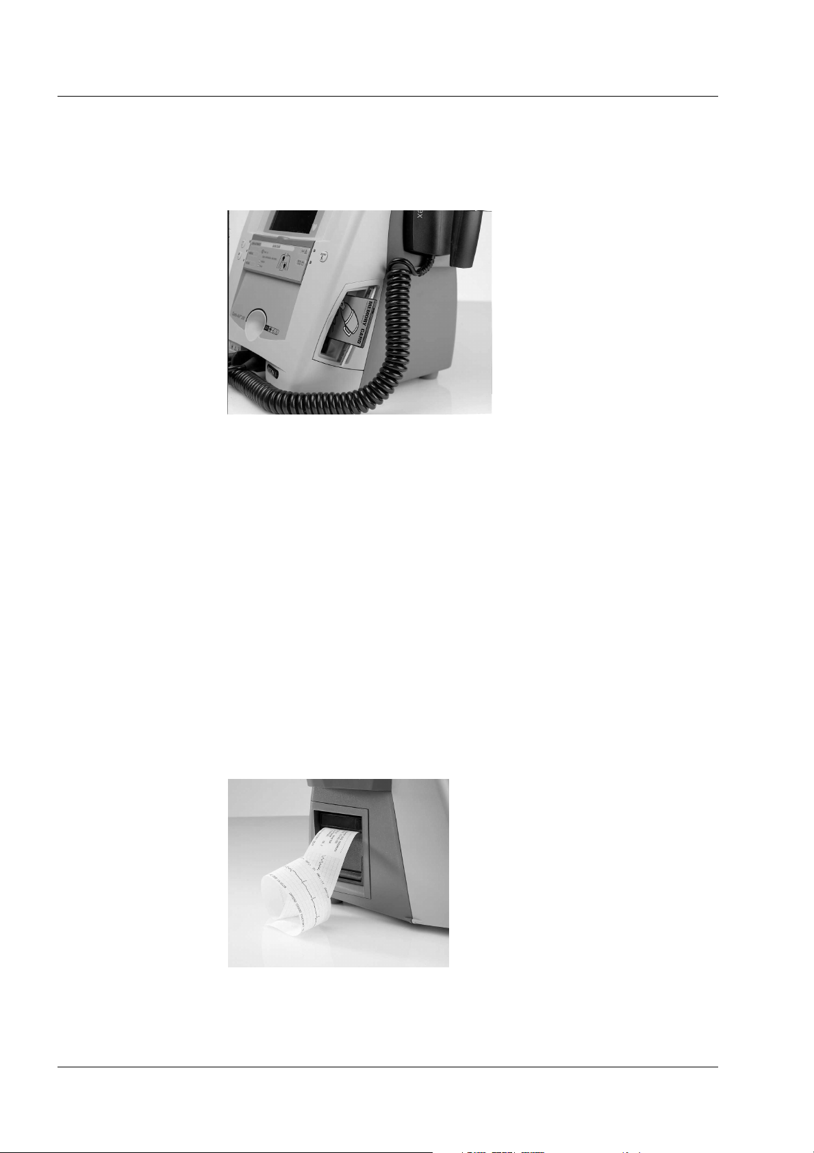
1.2.12 Printer (optional).
The printer provides an instant paper record of the ECG trace, or print a
record of other data such as the event report, settings or test results. It is an
OEM thermal printer containing an Artema character set to allow all specified languages to be printed.
The printer speed is 25/50 mm per second and the width is 50mm.
The ECG trace occupies 40mm.
Page 6, Artema MEC. A/S CA200, Service manual No. 95900-B
Chapter 1 – Introduction.
The product.
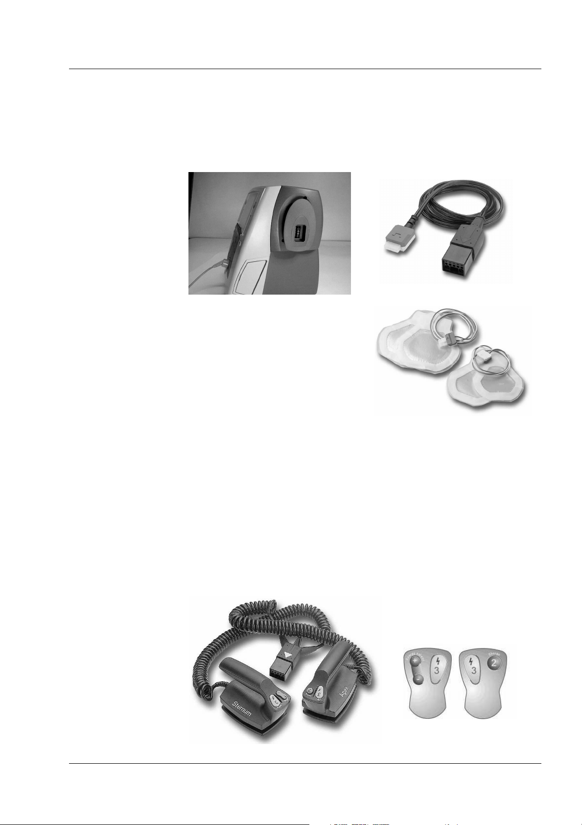
1.2.13 Pads.
The Cardio-Aid® can detect when pads are connected rather than paddles.
The instruction label on the cover (visible when closed) indicates where the
pads should be placed on the patient.
For test mode the pad connector can
be inserted into the Pad Test Socket
located on centre of the right pad
holder. (Only available on the variants with pads holders).
1.2.14 External paddles.
The right (Apex) paddle contains the Charge and one Shock key. The Charge
key is labelled ‘2’ and is referred to on the screen as “key 2”. The shock key is
labelled ‘3’ and is again referred to on the screen.
The Left (Sternum) paddle contains a Shock key labelled with ‘3’. There are
also plus and minus buttons, labelled ‘Energy’ The keys are only active in
Manual mode. These keys will change the energy level up or down and the
actual value can be seen at the display. If either is pressed, in manual mode,
while the unit is charging or is ready to shock, the unit will disarm.
Artema MEC. A/S CA200, Service manual No. 95900-B, Page 7
Chapter 1 – Introduction.
Installation.
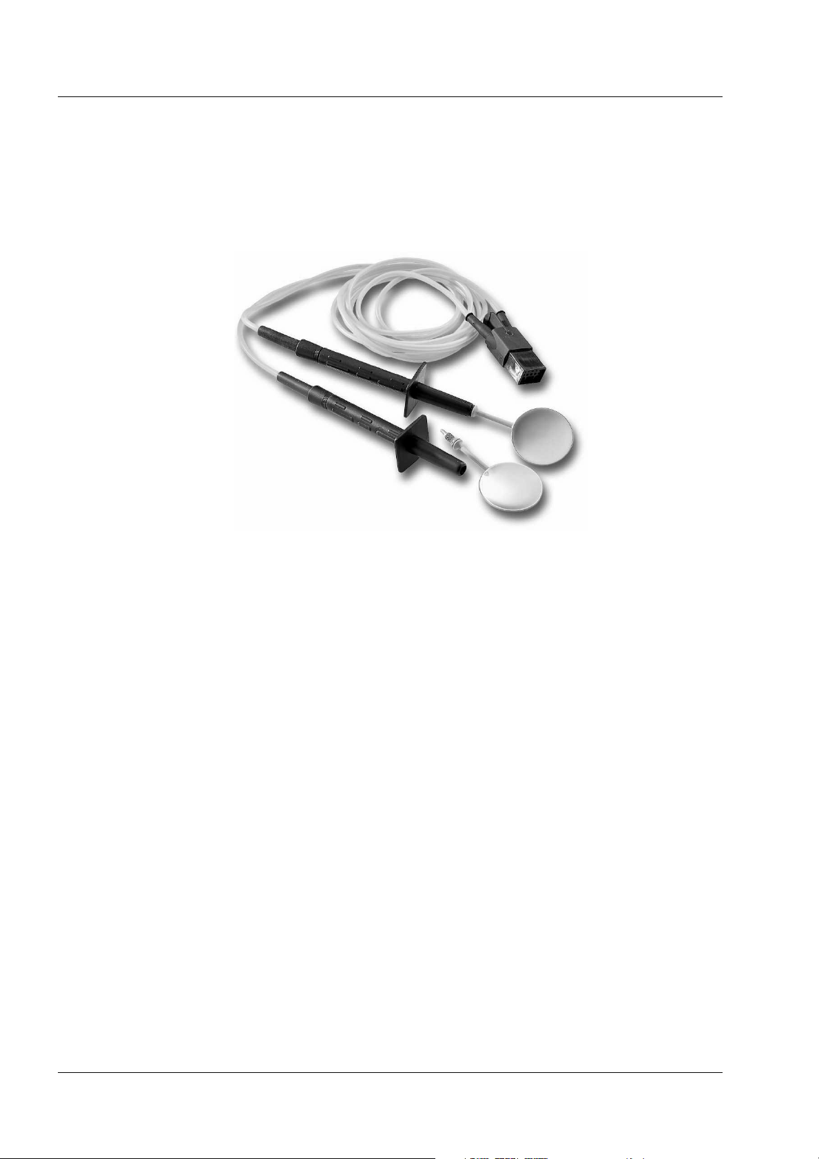
1.2.15 Internal paddles.
Similar to pads, the unit will be able to detect when internal paddles are
connected. The energy level will default to a lower value (configured in the
service menu). Inserting internal paddles will force the Cardio-Aid
manual mode.
®
into
1.3 Installation.
The Cardio-Aid® is intended for In-hospital use. To support the installation of
the defibrillator in different environments within the hospital a number of
suitable applications are made available to ease the mounting process.
The development of the Cardio-Aid® was not only aimed at a functional
design but also on a mechanical well balanced construction that can be used
as is. However, in order to provide the user with suitable mountings solutions
there has been developed a Trolley, Wall and Bed mount.
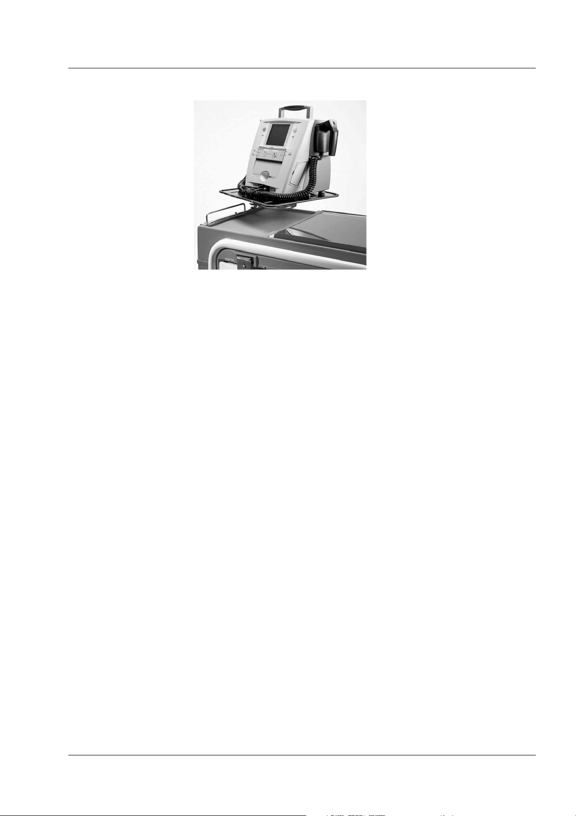
1.3.1 Trolley mount.
Basically 3 types of standard mounting scenarios are seen for mounting a
defibrillator on a trolley.
1. On a defibrillator swing arm, that is “raised” approximately 20-30 cm
above the main chassis of the emergency trolley.
2. On the top work base of an emergency trolley.
3. On the top plate of an equipment trolley.
Page 8, Artema MEC. A/S CA200, Service manual No. 95900-B
Chapter 1 – Introduction.
Installation.
Requirements:
It is important that the defibrillator can be secured properly from sliding,
tilting or dropping on the floor, while leaving the defibrillator controls unobstructed. Furthermore, it must be easy to detach the defibrillator from the
trolley.
Solution:
An easy to use metal plate that can be mounted on any flat surface. When
properly mounted the Cardio-Aid® slides onto the plate and uses the cut-
away sections for the positioning of the four feet.
1.3.2 Wall mount.
The Cardio-Aid® must be positioned in an upright position as close to the
wall as possible.
The wall mount is identical to the trolley mount, without any mechanical or
electrical connections. The wall mount will secure the Cardio-Aid
tor from sliding, tilting and dropping on the floor.
®
defibrilla-
Artema MEC. A/S CA200, Service manual No. 95900-B, Page 9
Chapter 1 – Introduction.
Installation.
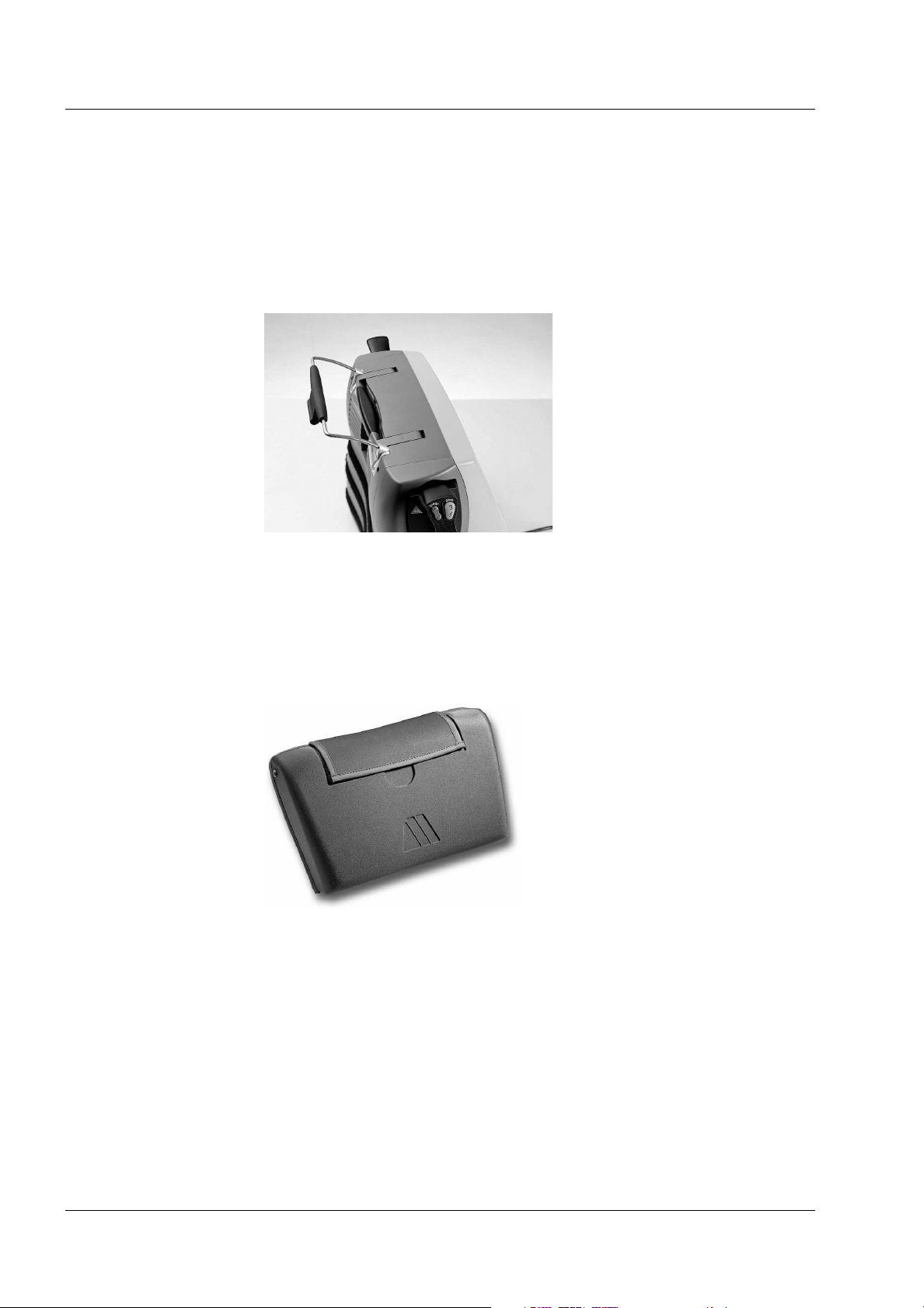
1.3.3 Bed mount.
A bed hook is integrated in the Cardio-Aid®‚by means of an optional bracket
that can be mounted next to the standard handle without obscuring the use
of this. By simply place the handle over the bed rail the Cardio-Aid® is
secured, leaving the controls unobstructed and the Cardio-Aid®‚ready for
immediate use during in-hospital transport situations.
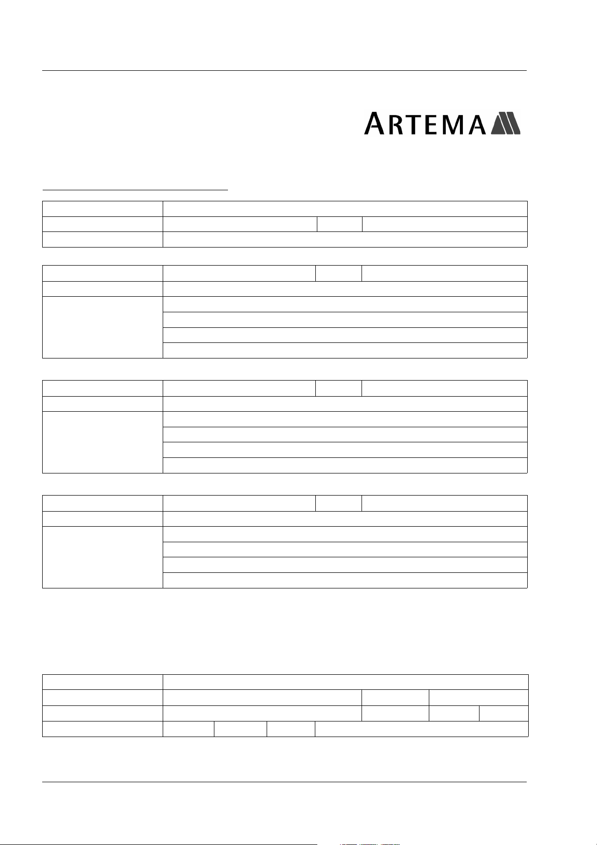
1.3.4 Bag.
To facilitate the use of the Cardio-Aid®‚a bag is made available (option) fulfilling multiple purposes such as easy storage of accessories and protection
of the device.
Page 10, Artema MEC. A/S CA200, Service manual No. 95900-B

Chapter 2 – Logbook.
Logbook.
Chapter 2 – Logbook.
2.1 Logbook.
This Artema Cardio-Aid® should be tested and, if necessary, serviced every 12 months from the date of
delivery. This service logbook is included for your convenience.
Date Initials Remark
Artema MEC. A/S CA200, Service manual No. 95900-B, Page 11
Chapter 2 – Logbook.
Goods to repair.
2.2 Goods to repair.
Goods to be repaired by Artema Monitoring and Emergency Care A/S
Date:
Company name:
Your ref.: Page of
Signature:
Part no.:
Serial no.:
Fault description: (please always indicate to secure quick repair)
Part no.:
Serial no.:
Fault description: (please always indicate to secure quick repair)
Part no.:
Serial no.:
Fault description: (please always indicate to secure quick repair)
Cat no.
Cat no.
Cat no.
Please ship to: Dan Transport A/S, Stenholm 19, DK-9400 Noerresundby, Denmark
Notify: Artema Monitoring and Emergency Care A/S, Aabybro
Destination: Aalborg Airport
To be fil l e d i n by Ar t e m a
Goods received on
Customer no. Original packing Yes No
Condition of goods Good Fair Poor
Page 12, Artema MEC. A/S CA200, Service manual No. 95900-B
Initials
Chapter 2 – Logbook.
Complaint form.
2.3 Complaint form.
This form is intended for problem reporting and is to be completed by authorized Artema MEC A/S representatives or distributors, and sent
to the:
Complain Manager Artema MEC A/S
Herstedvang 8
DK-2620 Albertslund
Phone +45 4386 7474
Fax +45 4362 1001
e-mail: artema@artema.dk
Product: Serial no.:
Software version: PCB/Module serial no.:
Operating hours: No of discharges:
Medical Consequence:
Tag as appropriate
Customer name:
Address:
User name:
Contact name:
Fax/Telex: Telephone:
Form completed by:
Company:
Signature: Date:
Was the unit applied or connected to a patient?
if Yes tag off one of the following statements
Cannot determine Medical Consequence from User Information
No Medical Consequence reported by user
Minor injury reported by User (give details under ‘Nature of problem’)
Death/serious injury reported by User. (give details under ‘Nature of problem’)
User believes death/serious injury could result if problem/incident reoccurs*
* if YES to this question please give the Users name and provide details of User’s concern under ‘Nature
of problem’
Yes No
Nature of problem:
For Artema’ internal use only Complaint no.:
Received: Signature:
Artema MEC. A/S CA200, Service manual No. 95900-B, Page 13

Chapter 2 – Logbook.
Complaint form.
Page 14, Artema MEC. A/S CA200, Service manual No. 95900-B
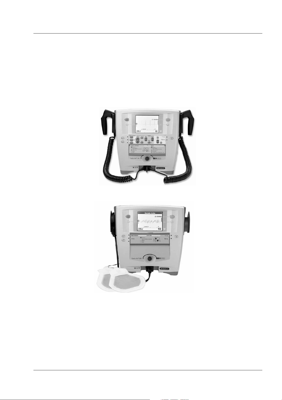
Chapter 3 – Technical description.
There are two basic standard versions available of the Cardio-Aid® defibrillator.
The only differences between the two versions are the cable/paddle holders
mounted on each side of the Cardio-Aid® defibrillator. The remaining part of
internal hardware and user interface are common for both versions.
.
Chapter 3 – Technical description.
Paddles version.
Pads version.
As an optional feature the Cardio-Aid® also may be equipped with a thermal
printer, as well as build-in pacer module for external pacing.
Artema MEC. A/S CA200, Service manual No. 95900-B, Page 15
Chapter 3 – Technical description.
Block description.
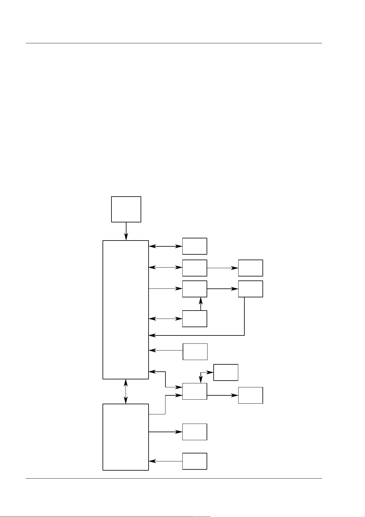
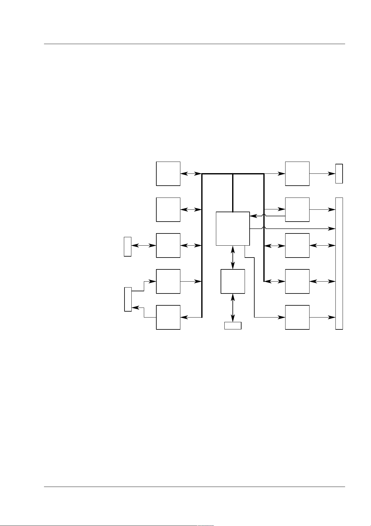
3.1 Block description.
The Cardio-Aid® electronics is build of the following circuits' boards:
Cables and board-to-board connectors make interconnections between the
different boards and all boards and wiring harness are assembled onto the
moulded inner chassis.
Processor board.
Defi controller board.
Paddle and cable ECG boards.
Power supply board.
Defi test boards.
Printer connection board.
Pacer board.
Cable ECG connector board.
Keyboard.
Power Supply
board
Defi board
(Defi Processor)
Paddle ECG
board
Cable ECG
board
High
Voltage
harness
Option:
Pacer board
HV-Test
board
Cable ECG
Connector
board
HV Socket
Battery Pack
Processor board
(Main Pro cessor)
Page 16, Artema MEC. A/S CA200, Service manual No. 95900-B
Printer
connection
board
Display
(LCD)
Keyboard
Option:
Printer unit
Chapter 3 – Technical description.
Block description.
3.1.1 Power management.
The internal Power distribution in the Cardio-Aid® takes place in two ways:
From the AC inlet placed on the rear side.
From a built in battery pack.
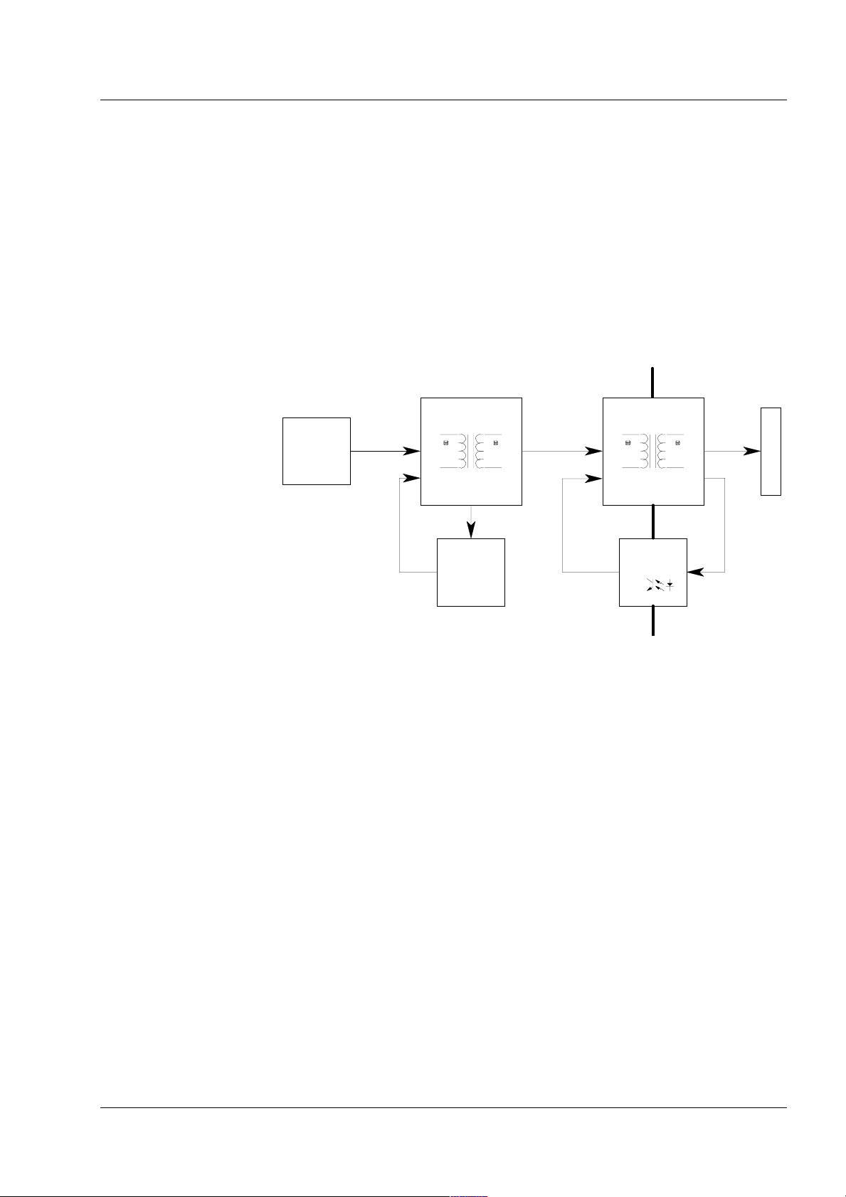
3.1.1.1 Power Supply board.
The Power Supply is a combined power factor controller and DC/DC converter.
The Power supply is designed to accept inputs levels from 100-240VAC and
to deliver a constant output power up to 60W and a peak power up to 200W.
J2
Mains inlet
connector,
fuses &
filtering
Power Factor
Corection
Power
Factor
regulation
Power Converter
400VDC 19VDC
PWM
voltage
regulation
Primary // secondary
isolation
The AC from the inlet is feed via the input filter network to the AC/DC converter, which is a combined power factor controller and rectification circuit.
The converted DC voltage supplies an isolated DC/DC converter, which delivers a regulated 19VDC-output voltage, used as system supply for the differ-
ent circuits' board inside the Cardio-Aid®.
The Power supply is protected against overload by help of two high breaking
capacity fuses placed into the AC inlet connector onto the rear side of the
®
Cardio-Aid
.
Output of the converter is electronically overload and overheat protected. If
an over-voltage is detected, the unit automatically will close down. Normal
operation is restored when the main voltage has been disconnected from the
AC inlet for a few seconds.
Artema MEC. A/S CA200, Service manual No. 95900-B, Page 17
Chapter 3 – Technical description.
Block description.
3.1.1.2 Battery-pack.
The battery pack are special designed for the Cardio-Aid
of 1,7Ah.
The battery pack comprises 10 accumulator-cells, delivering a total battery
voltage of 12 VDC. The cells temperature is readable by an internally thermistor, used by the charge controller placed onto the Defi board.
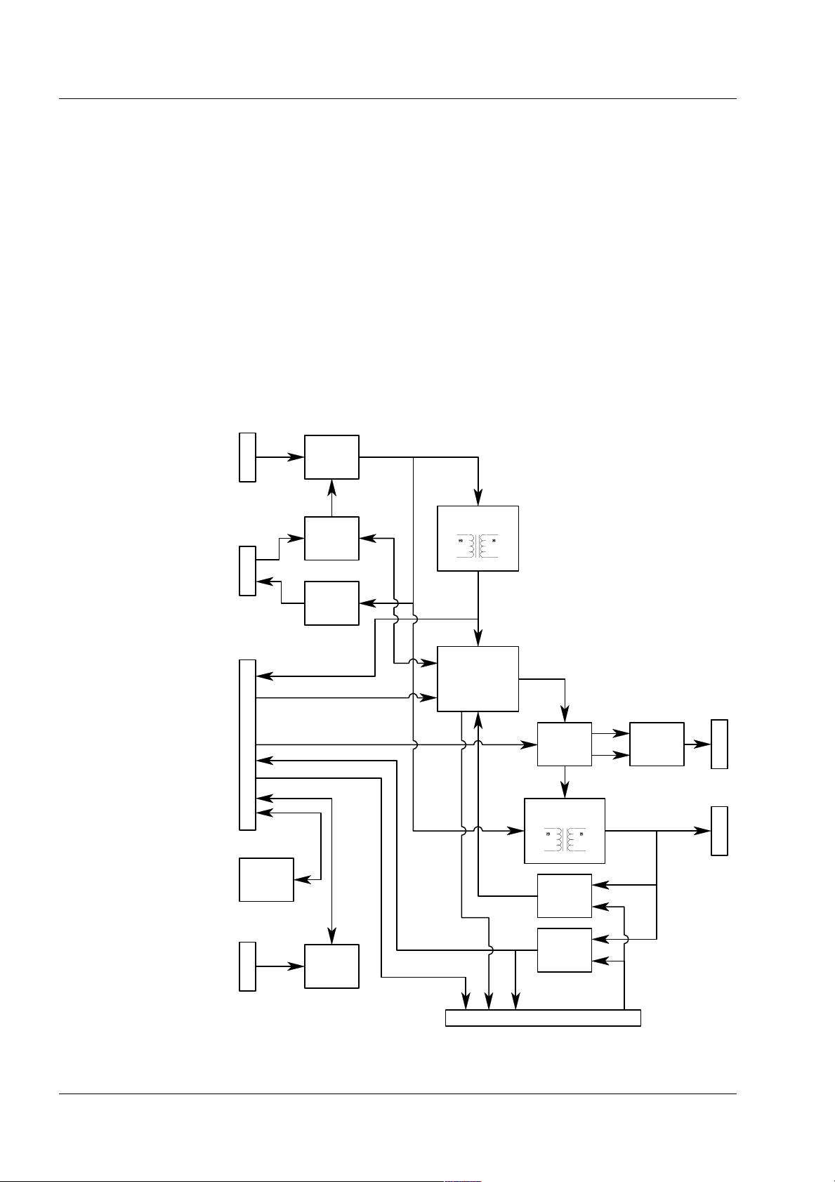
3.1.2 Defi board.
The Defi board includes following main functions:
®
and has a capacity
A multi-output converter.
A battery charger and monitor system for the built in battery.
Defi controller and safety control logic.
A high voltage generator.
Drain circuit for internal high voltage discharge.
J1
Power
merge
circuit
J405
J100
Cabl e
ECG-board
Pace trig
Battery
monitoring
Battery fast
charge
Multioutput
Converter
Defi Controller
Safety logic
High Voltage
Converter
Defi A/D
Converter
J3
Shock
Gate
J2
J112/J114
Paddle
ECG-board
Page 18, Artema MEC. A/S CA200, Service manual No. 95900-B
Processor
Converter
To Pacer opti on
A/D
J104

Chapter 3 – Technical description.
Block description.
3.1.3 Multi output converter.
The system or battery voltage from the merging circuits supplying the converter.
The converter outputs' supplying the different circuits locally on the Defi
board as well the Processor board with following voltages:
+5V dc.
+12V dc.
-28V dc.
2 x ±15V dc.
+ 13V dc. (only used for the printer).
The 15VDC outputs are galvanic isolated from the other outputs to ensure
the patient isolation between the ECG amplifier modules and other circuits.
The converter is over voltage protected and will latch the converter off in
fault conditions.
3.1.4 Battery fast-charge and energy monitoring.
The charging circuit ensures a comprehensive control of the battery charging
process to secure long lifetime for the battery. The circuit controls the charge
time and monitor the temperature in the accumulator-cells during charging.
The Defi controller monitors the actual energy supplied to and from the battery pack and data is used to inform the user about battery capacity.
A two-colored LED indicates the battery charge status on the front of the
Cardio-Aid®. Green indicates that the battery is fully charged and yellow
indicates battery is charging.
3.1.5 Defi Controller and safety logic.
The Defi controller and safety logic is for safety reasons designed as a twochannel system, where the Defi board controls the primary channel and the
Processor board the secondary channel.
The Defi controller is based on a single chip processor, which include serial
ports for communication locally onto the Defi board, parallel ports for interfacing to the processor board and other digital controls.
Any safety critical parameter analogue as well digital is monitored by the
two-channel system. If any of these parameters is exceeding defined limits,
the limits is brought into a safe state and an error message will be shown at
the display.
3.1.6 Shock gate.
The high voltage relay is switching between charging of the high voltage
capacitor and discharging energy to the patient. Both the relay and the
capacitor are placed outside the Defi board into the moulded inner chassis.
To control the relay the shock gate merges the shock control signals from the
two channels.
Artema MEC. A/S CA200, Service manual No. 95900-B, Page 19

Chapter 3 – Technical description.
Block description.
For executing a shock discharge both signals must be present at the same
time, which secure that both channels must be fully functional to deliver a
discharge.
3.1.7 High Voltage Generator.
The system voltage from the power merge circuit supplies the high Voltage
Generator, which is controlled by the safety logic.
In monitoring mode the generator is disabled and the high voltage capacitor
is shortened by a discharge/drain resistor placed onto the Defi board.
When a high voltage charging sequence is initiated, the primary channel
enables the generator and controls the voltage charging of the capacitor. The
second channel acts as a safety processor during the whole defibrillation
process.
3.1.8 ECG interface.
The Cardio-Aid® has two ECG modules placed onto the Defi board.
The Defi board acts only as a gateway for the serial communication between
ECG modules and the processor board. The communication takes place by
help of opto-coupler, to secure the patient isolation.
Page 20, Artema MEC. A/S CA200, Service manual No. 95900-B
Chapter 3 – Technical description.
3.1.9 Processor board.
The processor board includes the following main functions:
Microprocessor.
Flash memory and RAM.
Graphics circuit for a LCD.
Real Time Clock circuit.
Voice and sound generator.
Watchdog and reset circuit.
Interface for the Defi board.
ECG boards.
Printer, Memory card and Keyboard.
Memory
Flash &
RAM
Block description.
J4, J5
Display &
Graphics
inteface
J7
Real Time
Clock
Microprocessor
J3
PCMCIA
interface
J6
Keyboard
interface
Voice &
Sound
interface
(MC68340)
Printer
interface
J8
Watchdog
&Reset
circuit
ECG_Cab le_Tx
Serial
interface
for ECG
modules
Defi
Processor
interface
Defi safety
logic
interface
3.1.10 Flash PROM and RAM.
The boot software, programs code and Voice Data are stored in Flash PROM.
The program data is stored into static RAM with power back up during stand
by mode for data retention.
3.1.11 Controller for Liquid Crystal Display.
The LCD controller consists of a graphics microprocessor with separate video
memory. The display resolution is 320X240 pixels.
Communication to the graphic processor is controlled by the main processor
and the external display is directly connected to the graphic processor output. Contrast regulation circuitry and power supply for the display is also
included on the processor board.
Artema MEC. A/S CA200, Service manual No. 95900-B, Page 21

Chapter 3 – Technical description.
Block description.
3.1.12 Real Time Clock.
The real time clock is an integrated circuit which also contains a lithium battery and crystal clock. The lifetime of the lithium battery is more than 10
years.
The real time clock is integrated with an intelligent controller, which may
initiate a “Wake Up Test” by itself, if specified in the Cardio-Aid® configura-
tion menu.
3.1.13 Voice and sound generator.
The voice table for the voice processor is transferred via the Main processor
DMA channel. The converted voice data is merged together with volume and
sound data by an electronic potentiometer and fed to the loudspeaker.
3.1.14 Watchdog.
A watchdog circuit ensures that the program execution on the Cardio-Aid®
is fail-safe, by supervising the processor.
The processor must address a specific memory location in a certain interval
and if not, the Watch dog will time out and generate a global reset to several
®
circuits of the Cardio-Aid
A Watch-dog reset caused by an error will power off the Cardio-Aid
.
®
and an
error code may appear in the display next time the Cardio-Aid® is powered
on. After an error occurs, a fault LED placed on the front is flashing as well as
a piezo speaker will start beeping.
3.1.15 Defi controller interface.
To communicate with the defi processor, the processor sends and receives
command data via an eight-bit bi-directional port. A few additional safetycontrolling lines are fed separately to the Defi board.
3.1.16 ECG and Printer interface.
Communications to and from the Paddle and Cable ECG amplifier is implemented as serial signals via the Defi board.
The communication signals are feed to the processor via a separate UART on
the board and ECG signals processing takes place by the processor.
3.1.17 PCMCIA interface.
The interface is primarily used for storing obtained patient data onto a memory card.
The interface is also used when updating the Main and Basic software by
downloading either from a memory card. See also 4.2.3 PCMCIA connector.,
and 9.2 Equipment needed..
Page 22, Artema MEC. A/S CA200, Service manual No. 95900-B
 Loading...