

Page 1
MANUAL
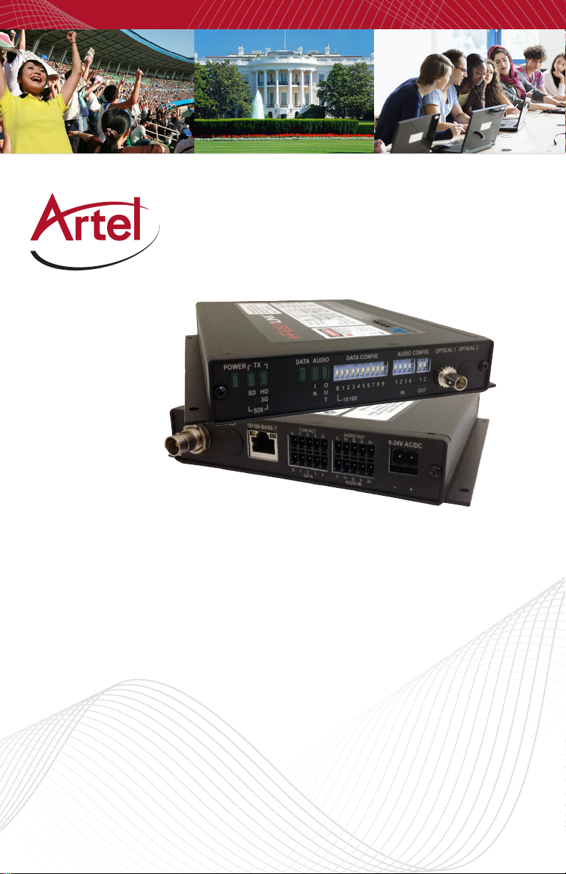
FiberLink
3390 Series
One-Way 3G/HD/SD-SDI
Transmission with two way audio,
data, 10/100 Ethernet & contact
closure over one or two fibers
Installation and Operations
Manual
WWW.ARTEL.COM
Page 2

FiberLink 3390Series
Contents
Contents
Model Part Number Specification ............................................... 4
General Specifications. . . . . . . . . . . . . . . . . . . . . . . . . . . . . . . . . . . . . . . . . . . . . . . . . . . . . . . . . . 4
Data Specifications ............................................................. 4
Audio Specifications ...........................................................5
Ethernet Specifications ......................................................... 5
Contact Closure Specifications .................................................6
Fiberlink 3390 Series Transmitter Specifications .................................6
Fiberlink 3391 Series Receiver Specifications ....................................7
Operating Loss Budget .........................................................8
Maximum Useable Distance ....................................................8
Installation Instructions ........................................................8
Installation Instructions (cont.) .................................................9
Audio Wiring - Inputs. . . . . . . . . . . . . . . . . . . . . . . . . . . . . . . . . . . . . . . . . . . . . . . . . . . . . . . . . . 10
Audio Wiring - Outputs ........................................................10
Reference Photos - Box Front/Rear ............................................10
Audio Input Switch Settings For Box Versions ..................................11
Audio Output Switch Settings For Box Versions ................................11
Data Configuration For Box Versions ...........................................11
Ethernet Configurations For Box Versions ......................................12
Baud Rate Configuration For Box Versions ......................................12
Data Wiring For Box Versions ..................................................13
Contact Closure Wiring For Box Versions .......................................13
Reference Photos - Card ......................................................14
Audio Input Switch Settings For Card Version ..................................14
Audio Output Switch Settings For Card Version ................................15
Data Configuration For Card Version ...........................................15
Data Baud Rate Configuration For Card Versions ...............................16
Ethernet Configurations For Card Version ......................................17
Data Wiring For Card Versions .................................................17
Contact Closure Wiring For Card Versions ......................................17
Alarm Switch Settings & Options ..............................................18
Alarm Switch Settings (Card Version Only) .....................................18
Indicator LEDs ................................................................19
Operating Pointers ............................................................20
Troubleshooting ..............................................................20
Maintenance and Repairs .....................................................21
Accessories and Related Products .............................................22
Page 2 FiberLink 3390 Series User’s Manual
Page 3

FiberLink 3390 Series
Welcome | Features | Package Contents
Welcome
Thank you for purchasing Artel Video Systems’ FiberLink 3390 Series. The 3390 Series is used
to transmit or receive 3G/HD/SD-SDI with two-way audio, 10/100 Ethernet, serial data, and
contact closure over one or two bers. The Fiberlink 3390 series is compatible with single
mode or multimode ber. The system delivers noise-free transmission that retains all of the
signals’ initial parameters. The 3390 Series also provides immunity to video pathological
signals over the entire link budget and operating temperature range.
Features
• Transmit (3390/3392) or Receive (3391/3393) 1 SDI channel
• Transmit and Receive 4 channels of audio (two each way)
• Transmit and Receive 1 channel of RS-Type data
• Transmit and Receive 10/100 Base-T Ethernet
• Transmit and Receive 1 channel of contact closure
• All channels are independent and available simultaneously
• SDI signal is equalized and re-clocked prior to ber optic transmission
• Receiver features a re-clocked SDI output
• Immunity to pathological patterns over entire link budget and operating
temperature range
• Compliant with SMPTE 259M-2006, 292-2006, 424M-2006, 276M
• Supports single mode and multimode ber
• One ber and two ber versions available
• Supports 3G/HD/SD-SDI inputs with or without embedded audio and data
• 14 dB Optical Link Budget @ 2.97 Gbps
• Wide operating temperature range: -10º C to +50º C
• Available in Box and Card versions
• ST or LC connectors available
• Designed and Manufactured in the USA by Artel
Package Contents
• One FiberLink Unit (3390, 3391, 3392, 3393)
• This User’s Manual
• One Ethernet Crossover Cable
Page 3FiberLink 3390 Series User’s Manual
Page 4
FiberLink 3390Series
Technical Specications
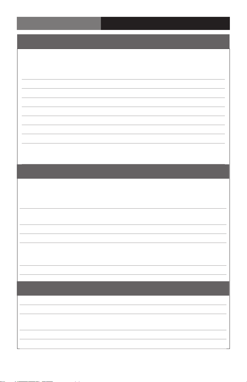
Model Part Number Specication
Unit Type Part Number
Box Card
Transmitter (1 Fiber, MM) 3390-B3z 3390-C3z
Transmitter (1 Fiber, SM) 3390-B7z 3390-C7z
Receiver (1 Fiber, MM) 3391-B3z 3391-C3z
Receiver (1 Fiber, SM) 3391-B7z 3391-C7z
Transmitter (2 Fibers, MM) 3392-B3S 3392-C3S
Transmitter (2 Fibers, SM 3392-B7S 3392-C7S
Receiver (2 Fibers, MM) 3393-B3z 3393-C3z
Receiver (2 Fibers, SM) 3393-B7z 3393-C7z
NOTE: “z” = variable to indentify the optical connector installed in the unit. We oer LC
and ST connectors. The part number will indicate each by replacing “z” with “L” or “S”.
General Specications
Indicators
Audio Activity, RS-Data Activity
Ethernet LEDs on RJ-45 Connector
Alarm (card version only)
Box Version Dimensions 6.5 W x 1.15 H x 8 L (inches)
165 W x 29 H x 203 L (mm)
Weight approx. 1 lb.; 0.45 kg
Number of slots in 6000A card cage 2
Power 9-24 volts, AC or DC
3390/92: 7.5 watts, 25.6 BTU/Hr
3391/93: 7.5 watts, 25.6 BTU/Hr
Operating Temperature -10ºC to +50ºC
Power, SDI TX, SDI RX,
Data Specications
Data Channels 1 Channel, Bi-Directional
Data Bandwidth DC to 115 Kb/sec, max.
Control Format Switch selectable RS-232, RS-422
& RS-485 (4 wire or 2 wire)
Protocols NRZ, NRZI, RZ, Manchester, Bi-phase
Signal Connector Removable terminal block
Page 4 FiberLink 3390 Series User’s Manual
Page 5
FiberLink 3390 Series
Technical Specications
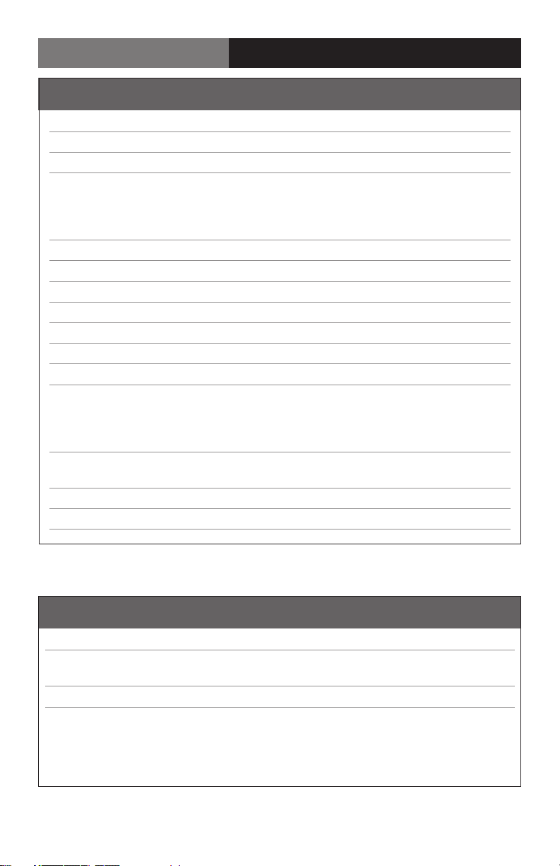
Audio Specications
Number of Audio Channels 2, balanced or unbalanced, bi-directional
Bits per sample/ Sampling Rate 24 bits, 78 kHz
Audio Connector Removable terminal block
Switches • Select input termination
• Balanced or unbalanced
input/output, selectable on a
per-channel basis
Frequency Response +0/-0.5 dB, 20 Hz - 20 kHz
Maximum Audio Level +10 dBu
Signal-to-Noise Ratio (A-weighted) 95 dB referenced full scale (balanced)
THD 0.002%, 20Hz - 20 kHz, full scale
Channel Phase Dierential ±0.1º
Crosstalk -100 dB (1kHz)
Audio Noise Level -85 dBm
System Gain Unity Gain, ±3%, input: balanced
600 ohms, 50 ohms source
impedance ; output: balanced into
600 ohms.
Input Impedance 600 Ohms terminated,
>24K ohms unterminated
Output Impedance 50 Ohms nominal
Audio to Video Di. Delay (skew) <300 usec
Ethernet Specications
Port 10/100 Base-T, Congured as MDI
Speed 10 Mbps & 100 Mbps Ethernet,
Switch Selectable
Ethernet Connector RJ-45
Page 5FiberLink 3390 Series User’s Manual
Page 6
FiberLink 3390Series
Technical Specications
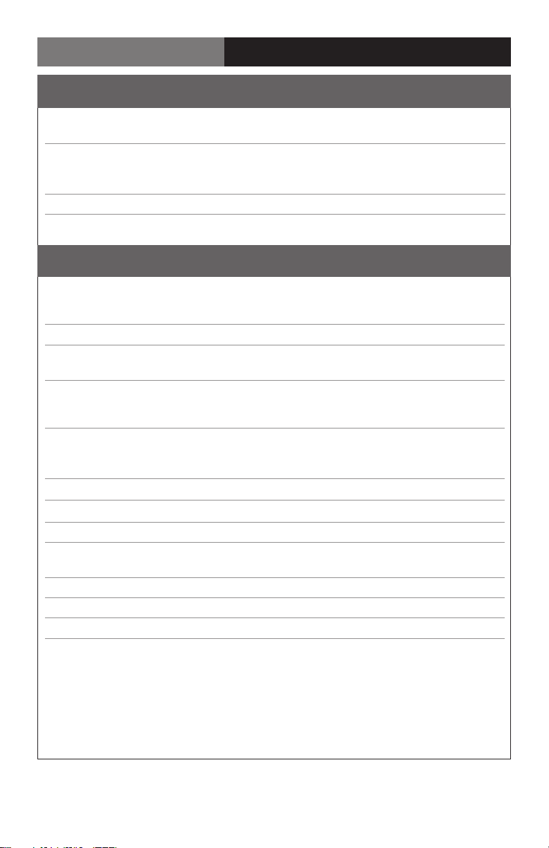
Contact Closure Specications
Contact Closure Input Dry contact or
TTL level referenced to GND
Contact Closure Output Isolated reed relay contacts;
115 Volts AC; 50/60 Hz @ 0.2 A or
24 Volts DC @ 1 A
Contact Closure Connectors Removeable terminal block
Fiberlink 3390 Series Transmitter Specications
Serial Video BNC Input Specications
Number of Inputs 1
Data Bandwidth 19.4 Mbps to 2.97 Gbps
Supported Standards SMPTE 259M, 292, 424M-2006, 305M
344M, DVB-ASI
Reclocked Data Rates
1.485 Gbps (SMPTE 292),
2.97 Gbps (SMPTE 424M-2006)
Equalization Automatic up to 100m of Belden
1694A at 2.97 Gbps, 200m at
1.485 Gbps and 350m at 270 Mbps
Return Loss >10dB up to 2.97 Gbps
Fiber Optic Output Specications
Connector LC or ST
Wavelengths Used 2-Fibers: 1310nm, 1490nm, 1550nm
Wavelengths Used 1-Fiber: 1510nm, 1530nm, 1550nm, 1570nm
Emmiter Type Laser
Output Power (nominal) -3.0 dBm
SDI Re-clocking At 270 Mbps, 1.485 Gbps & 2.97 Gbps
270 Mbps (SMPTE 259M, DVB-ASI-270),
Page 6 FiberLink 3390 Series User’s Manual
Page 7
FiberLink 3390 Series
Technical Specications
Fiberlink 3391 Series Receiver Specications
Serial Video BNC Output Specications
Number of Outputs 1
Signal Level 800mV ± 10%
DC Oset 0V ± 0.5V
Rise/Fall Time < 135 ps at 2.97 Gbps per SMPTE 424M;
< 270 ps at 1.485 Gbps per SMPTE 292;
0.4 ns to 1.5 ns at 270 Mbps
per SMPTE 259M
Overshoot < 10% of amplitude
Timing Jitter < 0.2 UI at 270 Mbps; < 1.0 UI at
1.485 Gbps; < 2.0 UI at 2.97 Gbps
with color bar signal
Alignment Jitter < 0.2 UI at 270 Mbps; < 0.2 UI at
1.485 Gbps; < 0.3 UI at 2.97 Gbps
with color bar signal
Re-clocking At 270 Mbps, 1.485 Gbps & 2.97 Gbps
Fiber Optic Input Specications
Connector LC or ST
Wavelength 1100 - 1620 nm
Minimum Input Sensitivity -17 dBm at 2.97 Gbps;
-19 dBm at 1.485 Gbps
-19 dBm at 270 Mbps;
Maximum Input Power 0 dBm
Page 7FiberLink 3390 Series User’s Manual
Page 8

FiberLink 3390Series
Operating Loss Budget | Maximum Useable Distance
Operating Loss Budget
Single Mode Fiber 0-14 dB at 2.97 Gbps
0-16 dB at 1.485 Gbps
0-16 dB at 270 Mbps
Multimode Fiber (62.5u) 0-14 dB at 2.97 Gbps
0-16 dB at 1.485 Gbps
0-16 dB at 270 Mbps
Multimode Fiber (50u) 0-14 dB at 2.97 Gbps
0-16 dB at 1.485 Gbps
0-16 dB at 270 Mbps
Maximum Useable Distance
Single Mode Fiber 30 km at 2.97 Gbps
40 km at 1.485 Gbps
40 km at 270 Mbps
Multimode Fiber (62.5u) 0.8 km at 2.97 Gbps
1 km at 1.485 Gbps
2.5 km at 270 Mbps
Multimode Fiber (50u) 1 km at 2.97 Gbps
1.3 km at 1.485 Gbps
3 km at 270 Mbps
*Distance specications are approximate, based upon connecting a 3390 Transmitter to a 3391 Receiver, and are not guaranteed.
Artel cannot estimate or guarantee operating loss budgets when the 3390 Series is used with other, non-Fiberlink devices.
Operating loss budget must not be exceeded
Installation Instructions
The FiberLink 3390 Series of ber optic transmission systems are ready for
immediate use and do not require any special tools or equipment.
The following instructions describe the typical installation procedure:
1) Connect the video source to the video input BNC connector on the transmitter unit.
2) Connect the video output cable to the video output BNC connector on the
receiver unit.
3) Congure the audio and data preferences as described in the appropriate sections
of this manual.
4) Connect the data connections as described in the Data Wiring section of this manual.
5) The Ethernet port is congured as an MDI port. If you are not connecting
the 3390 Series to an auto-crossover Ethernet port, you may need to use the Ethernet
crossover cable supplied with the unit to connect to another MDI port.
6) Connect the audio wiring as described in the Audio Wiring section of this manual.
Page 8 FiberLink 3390 Series User’s Manual
Page 9
FiberLink 3390 Series
Installation Instructions
Installation Instructions (cont.)
7) Connect the contact closure wiring as described in the Contact Closure Wiring section
of this manual.
8) Connect the ber optic cable(s) to the transmitter and receiver units.
Note: when using the two-ber version, you must connect transmitter “A” Optical
1 to receiver “B” Optical 1 and transmitter “A” Optical 2 to receiver “B” Optical 2.
9) Connect the Universal Power Supply to the transmitter and receiver units.
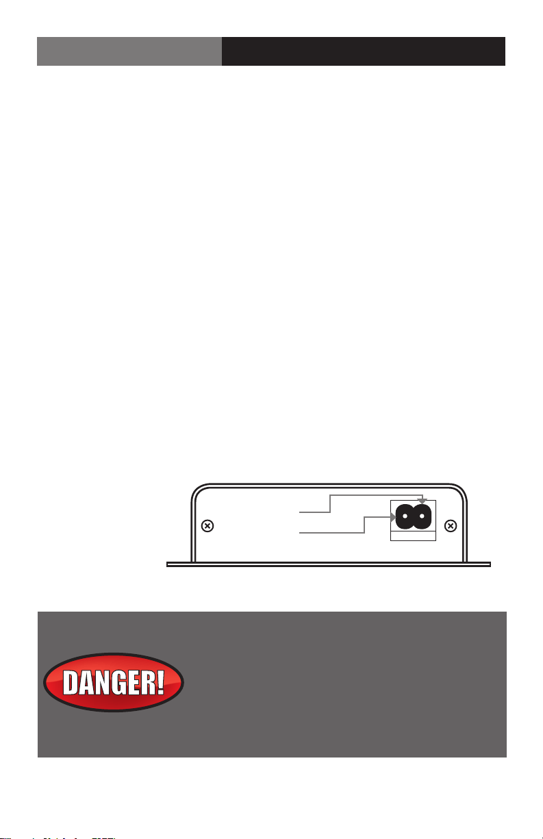
For box versions using DC power, please refer to gure 1.
10) When power is applied, the green POWER LED should illuminate, indicating the
presence of operating power. The 3G/HD/SD RATE, audio, and data LEDs will
give an indication as described in the Indicator LED’s and Alarm Circuitry section
of this manual.
11) The system should now be operational.
Note: The Rack Card version has an additional red LED for indicating the presence of an alarm
condition (loss of signal). Refer to Indicator LED’s and Alarm Circuitry sections of this manual.
Figure 1:
Power Connector
DC Input Polarity
(+) Positive
( - ) Negative
9-24 Volts
AC or DC
The transmitting element in the FiberLink 3390 transmitter
unit contains a solid state Laser Diode located in the optical
connector. This device emits invisible infrared electromagnetic radiation which can be harmful to human eyes. The
radiation from this optical connector, if viewed at close
range with no ber optic cable connected to the optical
connector, may be sucient intensity to cause
instantaneous damage to the retina of the eye. Direct
viewing of this radiation should be avoided at all times!
Page 9FiberLink 3390 Series User’s Manual
Page 10
FiberLink 3390Series
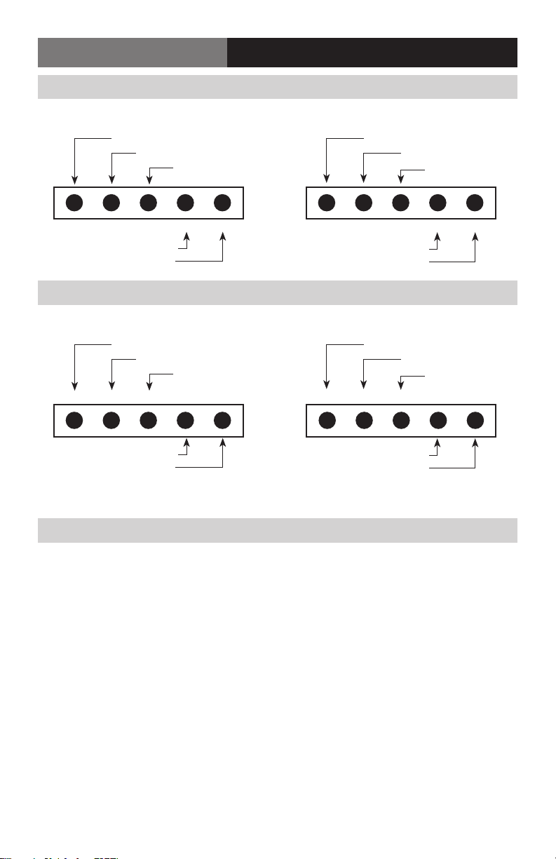
Audio Wiring - Inputs
Audio Wiring(All Versions)
Balanced
Channel 1 Input (-)
Channel 1 Input (+)
Ground (Shield)
1- 2-1+ 2+G
Channel 2 Input (-)
Channel 2 Input (+)
1- 2-1+ 2+G
Channel 2 Ground (-)
Audio Wiring - Outputs
Balanced
Channel 1 Output (-)
Channel 1 Output (+)
Ground (Shield)
1- 2-1+ 2+G 1- 2-1+ 2+G
Channel 2 Output (-)
Channel 2 Output (+)
Channel 2 Ground (-)
Un-Balanced
Channel 1 Ground (-)
Channel 1 Signal (+)
Shield
Channel 2 Signal (+)
Un-Balanced
Channel 1 Ground (-)
Channel 1 Signal (+)
Shield
Channel 2 Signal (+)
Reference Photos - Box Front/Rear
Page 10 FiberLink 3390 Series User’s Manual
Page 11
FiberLink 3390 Series
Data Switch Settings (Box Version)
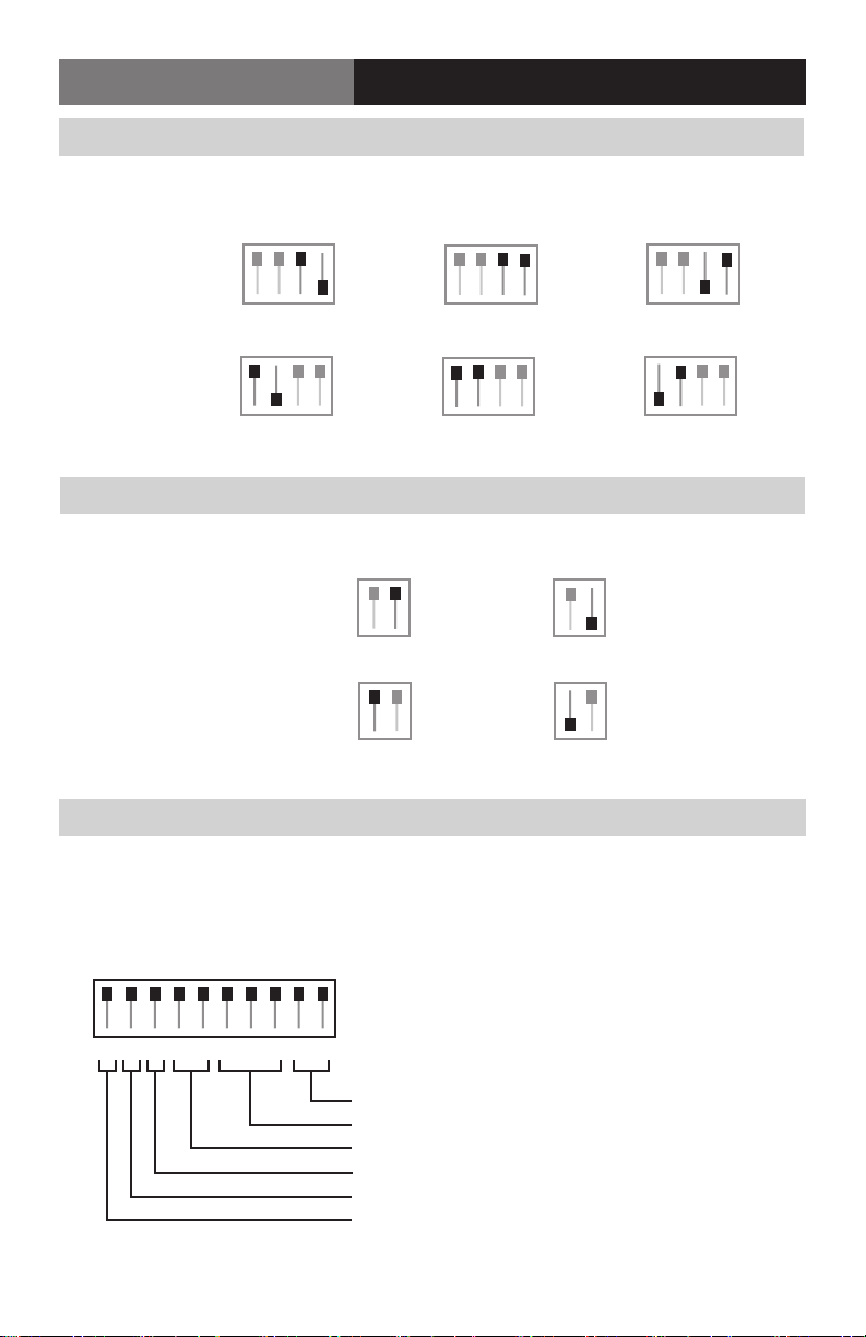
Audio Input Switch Settings For Box Versions
Channel # Balanced Balanced Unbalanced
(600 Ohms) (24k Ohms) (24k Ohms)
Channel 1
(controlled by
Switches 3 & 4)
1234 1234
1234
Channel 2
(controlled by
Switches 1 & 2)
1234
1234
1234
Audio Output Switch Settings For Box Versions
Channel # Balanced Unbalanced
Channel 1
(controlled by Switch 2)
12
12
Channel 2
(controlled by Switch 1)
12 12
Data Conguration For Box Versions
The Fiberlink 3390 Series box units have three switch blocks; one 10 position, one 4 posi-
tion, and one 2 position. The rst block, “Data Cong”, represents the Ethernet and RS
Channel congurations.
DATA CONFIG
E123456789
Data Mode
Baud Rate
2 Wire/4 Wire Mode
Input Termination (Up = Unterminated; Down=120 ohm)
Output Termination (Up = Unterminated; Down=120 ohm)
Ethernet
Page 11FiberLink 3390 Series User’s Manual
Page 12
FiberLink 3390Series
Data Conguration (Box Version)
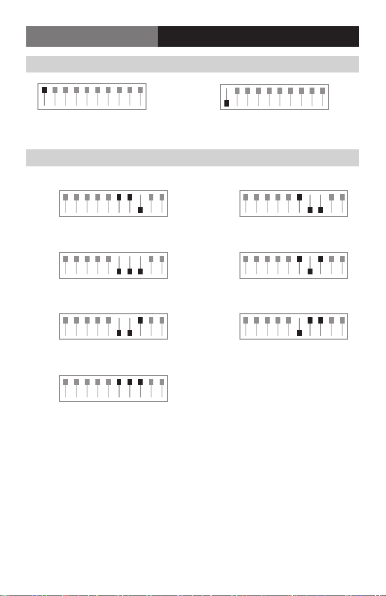
Ethernet Congurations For Box Versions
DATA CONFIG
100 Base-T Ethernet 10 Base-T Ethernet
DATA CONFIG
E123456789E123456789
Baud Rate Conguration For Box Versions
2400
9600
38.4k
76.8k
DATA CONFIG
E123456789
E123456789
DATA CONFIG
E123456789
DATA CONFIG
E123456789
DATA CONFIG
4800
E123456789
DATA CONFIGDATA CONFIG
19.2k
E123456789
DATA CONFIG
57.6k
E123456789
Page 12 FiberLink 3390 Series User’s Manual
Page 13
FiberLink 3390 Series
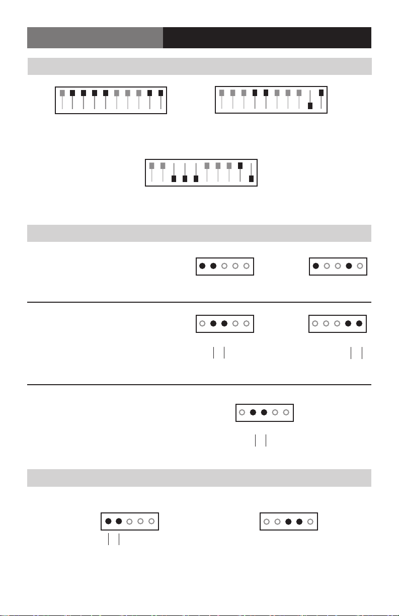
RS-Data Conguration For Box Versions
DATA CONFIG
Data Wiring (Box Version)
DATA CONFIG
E123456789
RS-232
E123456789
Data Wiring For Box Versions
RS-232
RS-422/485 - 4 Wire
DATA CONFIG
RS-485 - 2 Wire
Input
G1234
Input
G1234
E123456789
RS-422/485 - 4 Wire
Output
Output
+ –
G1234
G1234
+ –
RS-485 - 2 Wire
Input/ Output
Contact Closure Wiring For Box Versions
G123G
Input
+ –
G1234
+ –
G123G
Output
Page 13FiberLink 3390 Series User’s Manual
Page 14
FiberLink 3390Series
Reference Photos - Card
Images Coming Soon
Audio Conguration (Card Version)
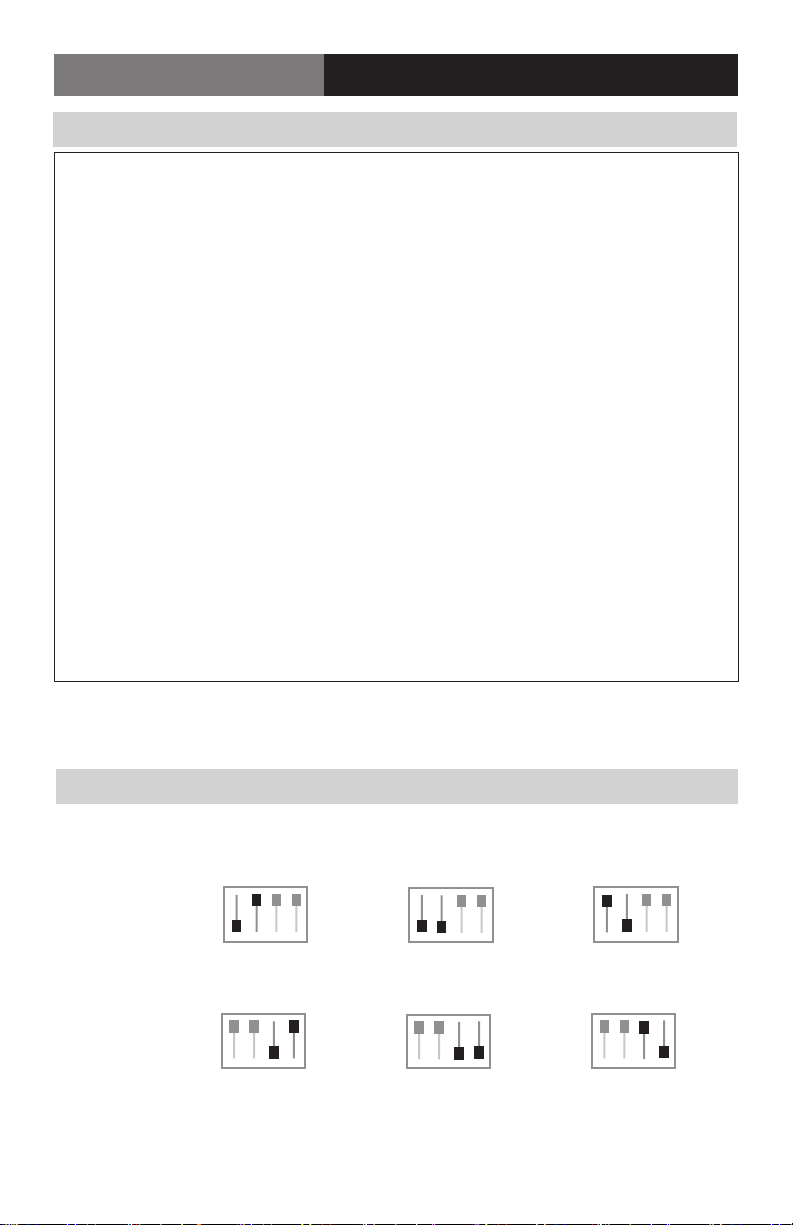
Audio Input Switch Settings For Card Version
Channel # Balanced Balanced Unbalanced
(600 Ohms) (24k Ohms) (24k Ohms)
Channel 1
(controlled by
Switches 1 & 2)
1234
1234
1234
Channel 2
(controlled by
Switches 3 & 4)
Page 14 FiberLink 3390 Series User’s Manual
1234
1234
1234
Page 15
FiberLink 3390 Series
Data Conguration Settings (Card Version)
Audio Output Switch Settings For Card Version
Channel # Balanced Unbalanced
Channel 1
(controlled by Switch 1)
12 12
Channel 2
(controlled by Switch 2)
12 12
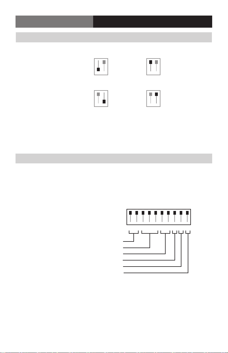
Data Conguration For Card Version
The Fiberlink 3390 Series card units have three switch blocks; one 10 position, one 4 posi-
tion, and one 2 position. The rst block, “Data Cong”, represents the Ethernet and RS
Channel congurations.
Data Mode
Baud Rate
2 Wire/4 Wire Mode
Input Termination (Down = Unterminated; Up =120 ohm)
Output Termination (Down = Unterminated; Up =120 ohm)
Ethernet
DATA CONFIG
12345678910
Page 15FiberLink 3390 Series User’s Manual
Page 16
FiberLink 3390Series
Data Conguration (Card Version)
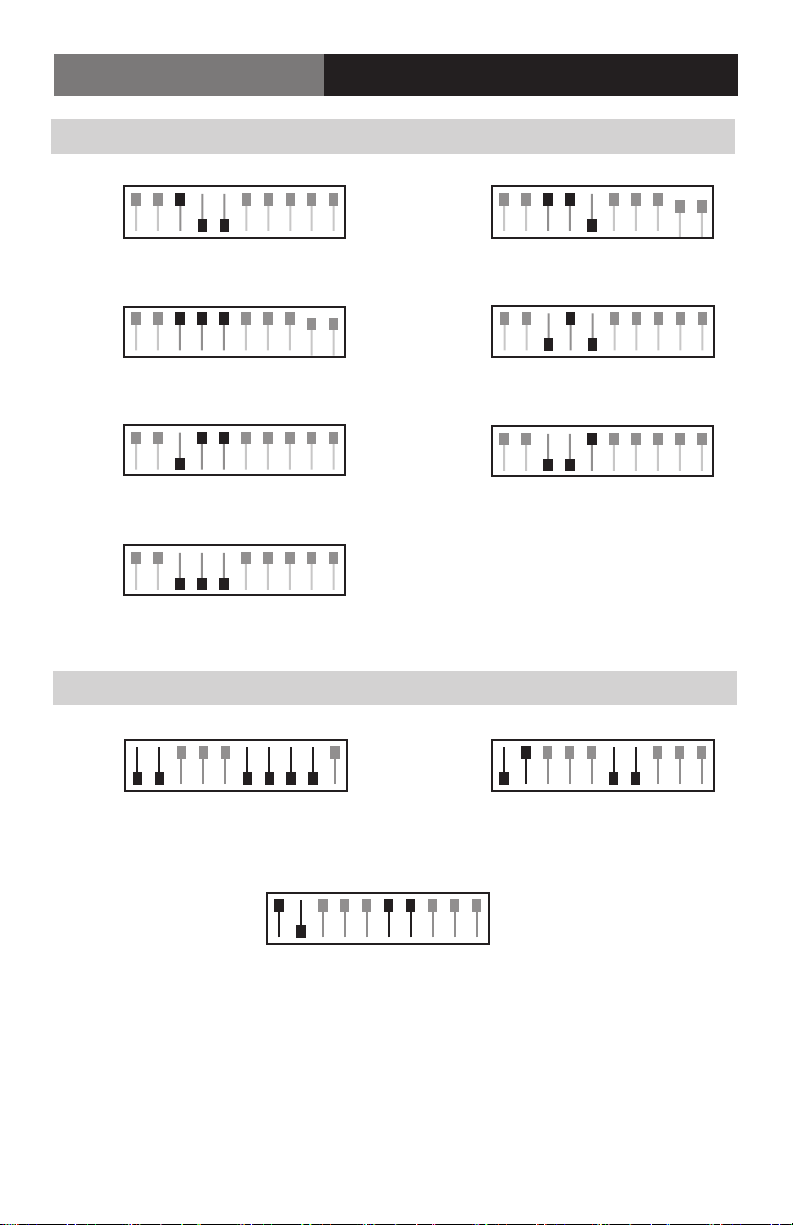
Data Baud Rate Conguration For Card Versions
DATA CONFIG
2400
12345678910
4800
12345678910
DATA CONFIG
9600
12345678910
19.2k
12345678910
DATA CONFIG
38.4k
12345678910
57.6k
12345678910
DATA CONFIG
76.8k
12345678910
Data Conguration Switch Settings for Card Versions
DATA CONFIG
DATA CONFIG
DATA CONFIG
DATA CONFIGDATA CONFIG
12345678910
RS-232
12345678910
RS-422/485 - 4 Wire
DATA CONFIG
12345678910
RS-485 - 2 Wire
Page 16 FiberLink 3390 Series User’s Manual
Page 17
FiberLink 3390 Series
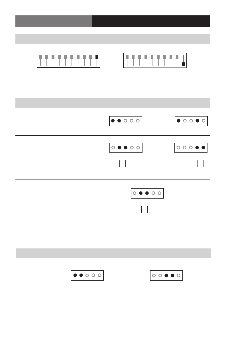
Ethernet Congurations For Card Version
Data Conguration (Card Version)
DATA CONFIG
12345678910
10 Base-T Ethernet 100 Base-T Ethernet
Data Wiring For Card Versions
RS-232
RS-422/485 - 4 Wire
Input Output
Input Output
RS-485 - 2 Wire
G1234 G1234
G1234
+ –
Input/ Output
DATA CONFIG
12345678910
G1234
+ –
G1234
Contact Closure Wiring For Card Versions
G123G
Input
+ –
+ –
G123G
Output
Page 17FiberLink 3390 Series User’s Manual
Page 18

FiberLink 3390Series
Alarm Switches (Card Version Only)
Alarm Switch Settings & Options
The Rack Card version of this product has an additional red indicator LED that illuminates
when an alarm condition exists.
The rack card unit also provides an output to drive a model 6020A Alarm Sensing Module
which provides an audible tone and activates a set of contacts for external signaling
purposes.
Alarm Switch Settings (Card Version Only)
Switch Position Alarm Indication Up Down
1 Loss of “Optical 1” Enabled Disabled
for 1 Fiber Version
2 Loss of “Optical 2” Enabled Disabled
for 2 Fiber Version
3 Loss of Receive Video Enabled Disabled
4 Loss of Transmit Video Enabled Disabled
Page 18 FiberLink 3390 Series User’s Manual
Page 19

FiberLink 3390 Series
Indicator LEDs
Indicator LEDs
The FiberLink 3390 Series has several indicator LEDs that are used to monitor the state of
the unit. Card versions have an additional Alarm LED.
3390, 3391, 3392, 3393 LED Denitions
LED Status Denition
Power On Indicates that correct power has been applied.
HD/3G TX O Indicates no HD/3G-SDI data rate lock (electrical)
On Indicates HD/3G-SDI data rate lock at 1.485 Gbps
or 2.97 Gbps
HD/3G RX O Indicates no HD/3G-SDI data rate lock (optical)
On Indicates HD/3G-SDI data rate lock at 1.485 Gbps
or 2.97 Gbps
SD TX O Indicates no SD-SDI data rate lock (electrical)
On Indicates SD-SDI data rate lock at 270 Mbps
SD RX O Indicates no SD-SDI data rate lock (optical)
On Indicates SD-SDI data rate lock at 270 Mbps
Audio In O Indicates no audio detected (electrical)
Blink Indicates audio detected (electrical)
Audio Out O Indicates no audio detected (optical)
Blink Indicates audio decected (optical)
Data O Indicates no data detected (electrical or optical)
Blink Indicates data detected (electrical or optical)
Alarm On Alarm Condition.
(See Alarm Settings section, page 18)
Note: The 3G, HD and SD LEDs indicators are o when a non-standard signal is applied.
Page 19FiberLink 3390 Series User’s Manual
Page 20

FiberLink 3390Series
Operating Pointers | Troubleshooting
Operating Pointers
Remember to check attenuation of the ber optic cable. The system will only operate
properly if these specications fall within the range of the system’s loss budget.
Note: If no electrical signals are applied to the Transceiver inputs, no optical power will be
present on the Transceiver’s optical output.
Troubleshooting
Multimode ber optic cable contains an optical ber with a light carrying “core” that is
only .0025 inches (62.5 microns) in diameter. Single mode ber optic cable has an even
smaller “core,” only .00032 to .0004 inches (8-10 microns). This is smaller than a human hair!
Therefore, any minute particles of dirt or dust can easily block the ber from accepting or
radiating light. To prevent this from happening, always use the provided dust caps when
ever optical connectors are exposed to air. It is also a good idea to gently clean the tip of an
optical connector with a lint-free cloth moistened with alcohol whenever dust is suspected.
The status of the LEDs should provide the rst clue as to the origin of any operational
failure. If these are o, it usually means that the ber is broken or has too much attenuation.
Next, be certain that the input and output signal connections are correct.
An optical power meter, such as the FiberLink 6650, a visible light source, such as the
FiberLink 6656, and a Two Wavelength Light Source, such as the FiberLink 6652/6654, can
greatly assist and expedite troubleshooting of ber optic transmission systems and are
recommended tools all installers should have available.
Finally, although multimode and single mode devices may look the same, they will not
operate properly together. Using the wrong device or ber can easily add more attenuation
than specied, resulting in poor overall performance. It should be noted that some of our
ber optic products support both single mode and multimode ber in the same unit.
If, after reviewing the above possibilities, the system is still not operating, please contact
the Customer Service Department for further assistance. If you suspect your problem is
caused by the optics or the ber optic cable, and you have an optical power meter, please
take the appropriate measurements prior to contacting support.
Page 20 FiberLink 3390 Series User’s Manual
Page 21

FiberLink 3390 Series
Maintenance and Repairs | Certications
Maintenance and Repairs
The FiberLink 3390 Series has been manufactured using the latest semiconductor devices
and techniques that electronic technology has to oer. They have been designed for long,
reliable and trouble-free service and are not normally eld repairable.
Should diculty be encountered, Artel Video Systems maintains a complete
service facility to render accurate, timely and reliable service of all products.
The only maintenance that can be provided by the user is to ascertain that optical
connectors are free of dust or dirt that could interfere with light transmission and that
electrical connections are secure and accurate. Please see the Troubleshooting section of
this manual for additional information.
An optical power meter, such as the FiberLink 6650, a visible light source, such as the
FiberLink 6656, and a Two Wavelength Light Source, such as the FiberLink 6652/6654, can
greatly assist and expedite troubleshooting of ber optic transmission systems and are
recommended tools all installers should have available.
All other questions or comments should be directed to our Customer Service Department.
It should be noted that many “problems” can easily be solved by a simple telephone call.
If you suspect your problem is caused by the optics or the ber optic cable, and you have
an optical power meter, please take the appropriate measurements prior to contacting
support.
Certications
Page 21FiberLink 3390 Series User’s Manual
Page 22
FiberLink 3390Series
Accessories and Related Products
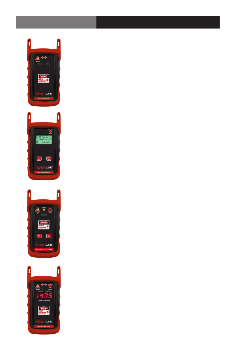
FiberLink 6656 Visible Light Source
The Fiberlink 6656 is a light-weight, hand-held tool used to
quickly troubleshoot faults in the continuity of both singlemode and multimode bers. High-intensity visible laser allows
for visible fault location of breaks and microbends in both
single-mode and multimode bers
FiberLink 6650 Optical Power Meter
The Fiberlink 6650 Optical Power Meter is a high accuracy, high
resolution, microprocessor controlled optical power meter. 65
dB dynamic range; calibrated to measure 850, 1300, 1310 and
1550nm. Works with multimode and single mode ber. Graphical LCD display with intuitive user interface with simple 2-key
operation.
FiberLink 6652/6654 Light Sources
The FiberLink Light Source oers a laser output at selectable
wavelengths, allowing for convenient, on-site testing of ber
networks during construction and maintenance procedures.
FiberLink 6658
The FiberLink Optical Length Meter measures the length of both
single mode and multimode ber with accuracy of ± 2.5 meters.
Generates a pulsed signal for use with ber identiers. Easy-toread bright red 7-segment LED display. Comes equipped with
industry preferred ST connectors.
Page 22 FiberLink 3390 Series User’s Manual
Page 23

FiberLink 3390 Series
Page 23FiberLink 3390 Series User’s Manual
Page 24
Proven Products, Unrivaled
Service, and Great Support
• High performance plug and play products
• Stand alone and card cage versions available
• Solutions for most video, audio, and data formats
• Multimode and single mode versions
• Designed and manufactured in the USA
• Training and installation support available
• 24x7x365 technical support available
Artel Video Systems Corp.
5B Lybert y Way,
Westford, MA 01886 USA
T: 978-263-5775
F: 978-263-9755
[email protected]
[email protected]
www.artel.com
All specifications subjec t to
change without notice.
©2016
Updated 02/16/2016
CS200-130182-00_D
 Loading...