

Page 1

AROTA-VQ100™
USER’S MANUAL
Page 2

Table of Contents
1 INTRODUCTION..........................................................................................................................................6
1.1 O
1.2 P
1.3 N
VERVIEW ..............................................................................................................................................6
RODUCT SUMMARY ..............................................................................................................................6
ETWORK CONFIGURATION ...................................................................................................................7
2 SYSTEM INSTALLATION..........................................................................................................................8
2.1 P
2.2 I
2.3 C
2.3.1 C
2.3.2 C
ACKAGE INSPECTION............................................................................................................................8
NSTALLATION..........................................................................................................................................9
ABLE CONNECTION ............................................................................................................................12
ABLES AND CONNECTOR SPECIFICATION......................................................................................12
ABLE INSTALLATION........................................................................................................................13
3 POWERING UP SYSTEM........................................................................................................................15
4 SYSTEM OPERATION.............................................................................................................................17
4.1 GUI
4.1.1 S
4.1.2 S
4.1.3 M
4.2 D
4.3 A
INSTALLATION................................................................................................................................17
ET UP A DRIVER...............................................................................................................................17
TARTING GUI..................................................................................................................................20
AIN FUNCTIONS..............................................................................................................................21
EFAULT VALUES..................................................................................................................................26
LARM FUNCTIONS...............................................................................................................................30
4.3.1 OMU................................................................................................................................................. 30
4.3.2 MODULES ......................................................................................................................................32
4.4 D
ESCRIPTION OF THE VALUE STATE......................................................................................................33
4.4.1 OMU................................................................................................................................................. 33
4.4.2 MODULES ......................................................................................................................................34
4.5 CONTROL
4.5.1 AGC
4.5.2 AGC
4.5.3 U
PPER AND LOWER LIMITS IN PD INPUT POWER..............................................................................37
4.5.4 GAIN
4.5.5 HPA
4.6.6 XCVR
4.6.7 MANUAL
4.6.8 MANUAL
4.6.9 A
UTOMATIC SHUT DOWN..................................................................................................................43
FUNCTIONS.......................................................................................................................35
ON...........................................................................................................................................35
OFF.........................................................................................................................................36
OFFSET................................................................................................................................38
ON/OFF...................................................................................................................................39
ON/OFF...............................................................................................................................40
SHUT DOWN ON.............................................................................................................41
SHUT DOWN OFF ...........................................................................................................42
4.6.10 FILTERS..........................................................................................................................................44
4.7 SUB
FUNCTIONS..................................................................................................................................46
4.7.1 DOWNLOAD...................................................................................................................................47
4.7.1.1 D
4.7.1.2 D
OWNLOAD SCREEN ....................................................................................................................47
OWNLOADING .............................................................................................................................48
4.7.2 DEBUG............................................................................................................................................51
5. PRODUCT DESCRIPTION......................................................................................................................52
5.1 S
5.2 P
5.3 U
5.3.1 S
5.3.1.1 PSU
5.3.1.2 MUX(M
5.3.1.3 A
5.3.1.4 W
5.3.1.5 B
YSTEM ARCHITECTURE ......................................................................................................................52
RODUCT VIEWS AND PHYSICAL DIMENSIONS ....................................................................................53
NIT DESCRIPTION...............................................................................................................................57
HELF ...............................................................................................................................................60
(POWER SUPPLY UNIT) .......................................................................................................61
ULTIPLEXER)....................................................................................................................63
LARM MONITORING UNIT............................................................................................................64
IRELESS MODEM .......................................................................................................................65
ACK BOARD ................................................................................................................................66
2
Page 3

AROTA-VQ100™ User Manual
5.3.1.6 GROUND .......................................................................................................................................67
5.3.2 OMU(O
5.3.3 FEU(F
5.3.4 XCVR
5.3.5 HPA
6 SYSTEM SPECIFICATIONS.................................................................................................................... 72
PERATING AND MANAGEMENT UNIT)...................................................................................68
RONT END UNIT)...................................................................................................................69
S(TRANSCEIVERS).................................................................................................................70
S(HIGH POWER AMPLIFIERS) ...................................................................................................70
6.1 G
6.1.1 T
ENERAL SPECIFICATIONS...................................................................................................................72
X/RX FREQUENCIES .......................................................................................................................72
6.1.1.1 LTE...............................................................................................................................................72
6.1.1.2 C
ELLULAR.....................................................................................................................................72
6.1.1.3 PCS..............................................................................................................................................72
6.1.1.4 AWS .........................................................................오류!
6.1.2 G
6.2 E
6.2.1 C
6.2.1.1 DL
6.2.1.2 DL
6.2.1.3 UL
ENERAL SPECIFICATIONS...............................................................................................................73
LECTRICAL SPECIFICATIONS ..............................................................................................................73
ELLULAR.........................................................................................................................................73
& UL COMMON SPECIFICATIONS ............................................................................................73
SPECIFICATIONS......................................................................................................................73
SPECIFICATIONS......................................................................................................................74
책갈피가 정의되어 있지 않습니다.
6.2.2 PCS..................................................................................................................................................74
6.2.2.1 DL
6.2.2.2 DL
6.2.2.3 UL
& UL COMMON SPECIFICATIONS ............................................................................................74
SPECIFICATIONS......................................................................................................................74
SPECIFICATIONS......................................................................................................................75
6.2.3 LTE...................................................................................................................................................75
6.2.3.1 DL
6.2.3.2 DL
6.2.3.3 UL
6.3 LED
6.4 M
6.4.1 M
6.4.2 E
& UL COMMON SPECIFICATIONS ............................................................................................75
SPECIFICATIONS......................................................................................................................75
SPECIFICATIONS......................................................................................................................76
& ALARM SPECIFICATIONS ...........................................................................................................77
ECHANICAL AND ENVIRONMENTAL SPECIFICATION ...........................................................................78
ECHANICAL SPECIFICATIONS.........................................................................................................78
NVIRONMENTAL ..............................................................................................................................78
7 TROUBLESHOOTING..............................................................................................................................79
7.1 G
7.2 D
7.3 U
ENERAL ..............................................................................................................................................79
OWNLINK ............................................................................................................................................79
PLINK..................................................................................................................................................80
8 GLOSSARIES............................................................................................................................................82
9 THE PREVION MVENTION MMEANMEANS OF SANS OATURATION
Table of Figures
FIGURE 1 NETWORK CONFIGURATION ...................................................................................................7
FIGURE 2 PACKAGING AND CONTENTS ..................................................................................................8
FIGURE 3 INDIVIDUAL PACKAGING AND CONTENTS...........................................................................9
FIGURE 4 SPACE CONSIDERATION FOR SHELF INSTALLATION.....................................................10
FIGURE 5 RACK GUIDE BAR INSTALLATION.........................................................................................10
FIGURE 6 MOVING AND INSTALLING THE REPEATER .......................................................................11
FIGURE 7 PLUGGING IN MODULES.........................................................................................................11
FIGURE 8 ILLUSTRATION OF FULLY EQUIPPED SHELF ....................................................................12
FIGURE 9 CABLE CONNECTION ( FRONT OF SHELF)........................................................................14
FIGURE 10 CABLE CONNECTION (BACK OF SHELF)..........................................................................14
FIGURE 11 INSTALLATION FILES..............................................................................................................17
FIGURE 12 MAIN WINDOW.........................................................................................................................20
FIGURE 13 SHELF MODULE SELECTION SCREEN .............................................................................21
FIGURE 14 STATUS MODE SCREEN........................................................................................................22
FIGURE 15 CONTROL MODE .....................................................................................................................23
FIGURE 16 CONTROL MODE SCREEN WITH NEW VALUES..............................................................24
3
Page 4

FIGURE 17 PCS DEFAULT VALUES..........................................................................................................26
FIGURE 18 CELLULAR BAND DEFAULT VALUE SCREEN...................................................................27
FIGURE 19 LTE-C BAND DEFAULT VALUE SCREEN............................................................................28
FIGURE 20 LTE A/B BAND DEFAULT VALUE SCREEN.........................................................................29
FIGURE 21 OMU SCREEN...........................................................................................................................30
FIGURE 22 MODULE SCREEN...................................................................................................................32
FIGURE 23 AGC ON......................................................................................................................................35
FIGURE 24 AGC OFF....................................................................................................................................36
FIGURE 25 SETTING UPPER AND LOWER LIMITS...............................................................................37
FIGURE 26 GAIN OFFSET...........................................................................................................................38
FIGURE 27 HPA ON/OFF..............................................................................................................................39
FIGURE 28 XCVR ON/OFF ..........................................................................................................................40
FIGURE 29 MANUAL SHUT DOWN ON..................................................................................................... 41
FIGURE 30 MANUAL SHUT DOWN OFF...................................................................................................42
FIGURE 31 SETTING UP ASD FOR OVERPOWER................................................................................43
FIGURE 32 FILTER SELECTION ................................................................................................................44
FIGURE 33 MAIN WINDOW (SUB SUB FUNCTIONS)............................................................................46
FIGURE 34 DOWNLOAD SCREEN ............................................................................................................47
FIGURE 35 DEBUG SCREEN......................................................................................................................51
FIGURE 36 SHELF FRONT SIDE CARDS.................................................................................................52
FIGURE 37 SYSTEM DIMENSION..............................................................................................................53
FIGURE 38 SHELF: FRONT.........................................................................................................................54
FIGURE 39 SHELF: BACK SIDE .................................................................................................................55
FIGURE 40 SHELF: TOP ..............................................................................................................................55
FIGURE 41 SHELF: SIDES...........................................................................................................................56
FIGURE 42 SHELF: BOTTOM......................................................................................................................57
FIGURE 43 SHELF CASE.............................................................................................................................60
FIGURE 44 SHELF: EQUIPPING MODULE CARDS ...............................................................................60
FIGURE 45 SHELF: FULLY EQUIPPED.....................................................................................................61
FIGURE 46 PSU .............................................................................................................................................62
FIGURE 47 MUX.............................................................................................................................................63
FIGURE 48 ALARM MONITORING UNIT...................................................................................................65
FIGURE
FIGURE 50 BACK BOARD ...........................................................................................................................67
FIGURE 51 GROUND CONNECTOR .........................................................................................................67
FIGURE 52 OMU ............................................................................................................................................68
FIGURE 53 FEU..............................................................................................................................................69
FIGURE 54 XCVR ..........................................................................................................................................70
FIGURE 55 HPA..............................................................................................................................................70
TABLES
TABLE 1 SYSTEM SUMMARY.......................................................................................................................6
TABLE 2 PACKAGING AND CONTENTS.....................................................................................................9
TABLE 3 FRONT CONNECTOR DESCRIPTIONS...................................................................................13
TABLE 4 REAR SIDE CONNECTOR DESCRIPTION..............................................................................13
TABLE 5 GENERAL ALARM.........................................................................................................................30
TABLE 6 UL ALARM.......................................................................................................................................30
TABLE 7 DL ALARM.......................................................................................................................................31
TABLE 8 OMU ALARM...................................................................................................................................31
TABLE 9 TEMPERATURE.............................................................................................................................31
TABLE 10 MODULES ON THE FRONT OF SHELF.................................................................................52
TABLE 11 UNITS.............................................................................................................................................57
TABLE 12 POWER CONSUMPTION PER UNIT.......................................................................................59
TABLE 13 PSU CAPACITY ...........................................................................................................................61
TABLE 14 PSU PIN MAP...............................................................................................................................62
TABLE 15 ALARM LED..................................................................................................................................69
TABLE 16 HPA ................................................................................................................................................71
49 WIRELESS MODEM.................................................................................................................66
4
Page 5

AROTA-VQ100™ User Manual
IMPORTANT NOTE:
FCC RF Radiation Exposure Statement:
This equipment complies with FCC RF radiation exposure limits set forth for an
uncontrolled environment. This equipment should be installed and operated with a
minimum distance of 20 centimeters between the radiator and your body.This
transmitter must not be co-located or operating in conjunction with any other antenna
or transmitter.
5
Page 6

AROTA-VQ100™
AROTA-VQ100(ARTECH Over The Air - Verizon Wireless Quad-band 100k square
feet System)
1 Introduction
1.1 Overview
AROTA-VQ100K is a quad-band OTA repeater for Verizon Wireless to offer in-building
coverage up to 100K sq. ft. The system provides the digital filter technology enabling the
customer to have a flexible sub-band frequency selection.
The repeater system is designed for modular architecture with rack mountable structure so
that the customer can equip the particular radio module(s) based upon the market demand.
The system supports the following frequency bands and OTA technologies:
700Mhz for LTE,
850MHz for CDMA CELLULAR,
1900Mhz for CDMA PCS .
Each band can be supported by simply plugging in individual modules
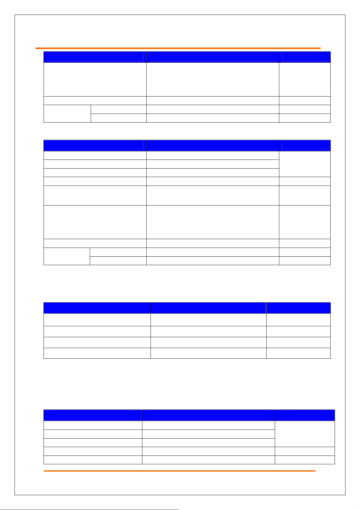
1.2 Product Summary
Item Specification Remarks
Type Shelf (Standard 19” Rack Mountable)
Size(mm, W x H x D)
Weight 61kg(Full equipped except for AWS)
Input Power AC120V/A
Power consumption 700W(Full mounted)
Power Connector Terminal Block 3P
RF IN/OUT Port Location SMA, N-Type/FEU(F ront End Unit)
482.8(19″) X 355(8U) X560
Circumstance -5 ~ 50 (Operating Temperature)℃℃
Table 1 System Summary
6
Page 7

AROTA-VQ100™ User Manual
1.3 Network Configuration
The in-building repeater system provides coverage to shadow areas in the building. The
network configuration is illustrated in Figure 1. In general, the configuration consists of
Donor antenna~ Shelf ~ Directional coupler ~ 2 or 3 way splitter ~ Indoor omni-antenna.
Figure 1 Network Configuration
7
Page 8

2 System Installation
1. Ensure the installation site is appropriate in terms of temperature and humidity.
2. Install a standard 19 inch rack if necessary.
3. Mount the repeater shelf on the rack with screws.
4. Connect ground cable to the repeater shelf.
5. Plug a power cable into the AC input connector on the FEU unit .
6. Connect a RJ-45 jack to Ethernet Port on the front of OMU unit for communication
with NOC.
2.1 Package Inspection
Visually inspect the repeater unit and other accessories for any damage.
.
Figure 2 Packaging and Contents
8
Page 9

AROTA-VQ100™ User Manual
Package Item Qty Unit Remarks
BOX1
BOX2
(FEU Unit Included)
Installation guideline 1 Copy
OMU, XCVR & HPA UNITs 1 Set
MOUNTING BRACKET 1 Set
Shelf
Power Cable 1 EA AC Supply
User Manual 1 Copy
Inspection Sheet 1 Copy
Table 2 Packaging and Contents
1 Set
[BOX1 : SHELF] [BOX2 : XCVR & HPA UNITs]
Figure 3 Individual Packaging and Contents
2.2 Installation
The installation procedures are described in this section. Please carefully follow the
instructions below when installing the repeater unit.
Check the rack and shelf location
1. Prepare a 19 inch standard rack.
2. Choose a location considering air flowing inside the shelf. (An inner Fan is making air
blowing downward from top to bottom)
3. Install the shelf securing 1U~2U free space for stability and effective heat dissipation
system on the device.
9
Page 10

Figure 4 Space Consideration for Shelf Installation
Installing a guide in the rack
1. Check the rack whether a guide bar is already installed to support the weight of the
shelf.
2. If there is not, Use guide bar from the package and install it in the rack as shown in
Figure 5.
Figure 5 Rack Guide Bar Installation
10
Page 11

AROTA-VQ100™ User Manual
Moving and installing the Repeater Shelf
1. A two-person team should carry the shelf for safety.
2. Put the shelf on the bracket of 19” rack and push it into the end of the rack to mount.
3. Fasten both sides of the shelf with screws in the rack.
Figure 6 Moving and Installing the Repeater
Module Installation
1. Inspect the shelf to ensure the shelf is securely mounted in the rack.
2. Ensure FEU unit is located at the leftmost slot and mount other modules to the shelf..
3. Insert OMU unit into the top horizontal slot first and then, tighten up 2 captive screw
on the both sides.
4. Before inserting modules, compare all names of modules printed on the bottom of
OMU unit with each name that is also printed on every front side of unit. Then,
secure the modules by fastening the screws..
11
Figure 7 Plugging in Modules
Page 12

Complete installation of a shelf (Fully Equipped)
1. Insert all modules into the proper slots as shown in Figure 8.
2. Double-check the modules with their each name printed on the front side of OMU unit.
Figure 8 Illustration of Fully Equipped Shelf
2.3 Cable Connection
2.3.1 Cables and Connector Specification
The connectors used for the repeater are described below.
12
Page 13

AROTA-VQ100™ User Manual
Num Name Connection Connector Ty pe
① DONOR1(LTE/CELL) Donor ANT1 for LTE/CELL UL/DL_N Type Female
② DONOR1 MON Donor Monitoring Port SMA Male
③ DONOR2(PCS/AWS) Donor ANT2 for PCS/AWS UL/DL_N Type Female
④ DONOR2 MON Port of measuring instrument SMA Male
⑤ COVERAGE Coverage ANT for ALL UL/DL_N T ype Female
⑥ COVERAGE MON
⑦ AC INPUT(110V) AC (110V) Outlet
⑧ DEBUG USB port of PC USB Type-B Female
⑨ GUI Network port of PC RJ-45
Table 3 Front Connector Descriptions
Num Name Connection Connector Type
1 GROUND Ground Cable Ground Cable Connector
Table 4 Rear Side Connector Description
2.3.2 Cable Installation
Cable Length
Before installing antenna cables, ensure that the lengths of the antenna cables are
proper so that the cable loss will not affect optimal service.
SHELF Cable Connection on the Front Panel
Monitoring Port for Coverage
Ant.
SMA Male
1. Check for types of service required for the installation site. (e.g. LTE C band)
2. Confirm the names of the connectors on the front panel as shown in Figure 9.
3. Connect the cable for DONOR1 (LTE/CELL) to a topmost port on FEU Card.
4. Connect the cable for DONOR2 (PCS/AWS) to port located at the second from the
top port on FEU Card.
5. Terminate ports that will not be in service with 50Ohm terminator
6. Connect the cable for Coverage Antenna to port located at the third from the top port
on FEU Card.
7. Connect 120V AC power cable to the bottom port.
13
Page 14

Figure 9 Cable Connection (Front of Shelf)
Cable Connection on the rear panel
Connect a ground cable to the ground connector on the rear panel as shown in Figure
10. The ground connection should be made according to the safety the regulation.
Figure 10 Cable Connection (Back of shelf)
14
Page 15

AROTA-VQ100™ User Manual
3 Powering Up System
When the normal operation conditions such as cable connections, shelf installation,
input power level, communication with NOC are met, power up the system following the
procedures below.
SW ON
1. Make sure all switches are on OFF position.
2. Locate switches for each modules as shown below..
- MAIN S/W : Bottom of Front FEU Card.
- HPA S/Ws : Bottom of each HPA’s.
3. Turn ON MAIN switch as in figure .①
4. Turn ON HPA switch as in figure ②
5. Make sure to turn OFF the switch when removing HPA card from the shelf..
15
Page 16

Verifying ALARM LED
When the system is operating normally
after power-up, the LED’s should be all
GREEN. After verifying the LED’s are all
green, the next steps can be followed. If
any of the LED’s does display GREEN,
please refer to Chapter 7, Troubleshooting
and Recovery
.
GUI Installation and Operation
Refer to section 4.1 for procedures to download, install and use the GUI..
GUI Default Values
1. AGC OUTPUT LEVEL is set to be the maximum output power possible by default.
Please refer to [4.6.1 AGC ON Setup] and adjust AGC OUTPUT LEVEL to a desired
level.
2. Default status of XCVR is OFF. Please turn it ON while referring to [4.6.1 XCVR
ON/OFF Setting].
3. Default status of HPA is OFF. Please turn it ON while referring to [4.6.5 XCVR ON/OFF
Setting].
16
Page 17

AROTA-VQ100™ User Manual
4 System Operation
4.1 GUI Installation
The GUI program of AROTA_VQ100 contains installation files in Figure 11.
Figure 11 Installation Files
4.1.1 Set up a driver
When a USB port is connected to a PC, the set-up message will pop up as below. Set
an installation path as the directory containing GUI first and then start to install a driver.
17
Driver Setup 1
Page 18

Driver Setup 2
Driver Setup 3
18
Page 19

AROTA-VQ100™ User Manual
Driver Setup 4
19
Driver Setup 5
Page 20

4.1.2 Starting GUI
When you run AROTA_VQ100, a pop-up to select communication method with main
board will come on.
- If the port cannot be connected, error message will be shown up as below.
- Check the USB connection and try again if “Port Open Failed” message appears.
Note. 1
Port Fail
Note. 2
Note. 3
Note. 4
Figure 12 Main Window
20
Page 21

AROTA-VQ100™ User Manual
Note. Description
1
2
3
4
Display the version of GUI
Reset all modules and systems including main board
Displays communication status with main board.
Show communication connection with main board
-Tx: The red light comes on during data transmission from GUI to the main board.
-Rx: The red light comes on during data transmission from GUI to the main board.
4.1.3 Main Functions
If you move your mouse to the location showing each module on front shelf, the
green- line border will turn up to the screen around the module in Figure.14.
You can check the status of LED
lamp on the repeater
Figure 13 Shelf module Selection Screen
If any part of a module is
clicked, the screen will show
Status/Control of the module.
21
Page 22

Basic setup of modules
The interface and input method of all modules excluding OMU, FEU and AWS are identical.
Step 1 Shows Status-Mode
screen.
Closes current status
display
Figure 14 Status Mode Screen
22
Page 23

AROTA-VQ100™ User Manual
Step 2. If the control window
shows up, values can be changed.
Figure 15 Control Mode
23
Page 24

Step 3. If any value has
changed, ”Apply” button will appear.
When clicked, new values will be
made effective and the screen returns
to Status-Mode.
* * If there is no need to
enter a value, just click it. It
will go back to the status
mode as in Figure. 14.
Figure 16 Control Mode Screen with New Values
- When “Apply” button is pressed or “Enter” key is pressed after changing a value, a
confirmation window will appear as below.
- If “Yes” is clicked, the window below will appear while change is being made effective from
the modules.
24
Page 25

AROTA-VQ100™ User Manual
Control Command Execution Window
- If there is no response from the modules, the commands will be timed out and no change
will be applied..
Timeout Window
25
Page 26

4.2 Default Values
Figure 17 PCS Band Default Values Screen
26
Page 27

AROTA-VQ100™ User Manual
27
Figure 18 Cellular Band Default Value Screen
Page 28

Figure 19 LTE-C Band Default Value Screen
28
Page 29

AROTA-VQ100™ User Manual
29
Figure 20 LTE A/B Band Default Value Screen
Page 30

4.3 Alarm Functions
4.3.1 OMU
Table 9.
Table 5.
Table 6.
Table 8.
Table 7.
Figure 21 OMU Screen
Power Supply out of range Problem with power supply
Tamper detected Not used
Communication failure Communication problem with high rank center
Heartbeat Not used
Field replaceable module failure Replaceable module failure
Reset alarm Reset is activated
Manual shut down alarm Manual shutdown is activated
Power Supply out of range Problem with power supply
Table 5 General Alarm
Oscillation detected Problem with oscillation detected
Hardware failure Hardware abnormal
Synthesizer failure PLL unlock detected
Software failure Software abnormal
Power at coverage port too high Input power at coverage port too high
Out of band out of emission spec Filter rejection abnormal
Table 6 UL Alarm
30
Page 31

AROTA-VQ100™ User Manual
Donor power too high/low Input power at donor port too high/low
Hardware failure Hardware abnormal
Low isolation Problem with low oscillation detected
Software failure Software abnormal
Synthesizer failure PLL unlock detected
Spurious emissions out of spec Spurious emissions out of FCC limits
Interfered power exceeded Filter rejection abnormal
Table 7 DL Alarm
LINK Communication problem with modules
PSU Power Supply abnormal
FAN A,B Fan abnormal
Alarm Mon Unit H/W Failure Alarm monitoring unit hardware abnormal
Table 8 OMU Alarm
HIGH Temperature is above upper threshold
LOW Temperature is below lower threshold
Table 9 Temperature
31
Page 32

4.3.2 MODULES
Note. 1 Note. 2
Note. 4
Note. 5
Note. 3
Note. 6 Note. 7
Figure 22 Module Screen
Note.
1
2
3
4
5
6
7
Communication Problem with MAIN CONTROL BOARD
Description
Module Equipped
PLL LOCK Status
Below Lower Threshold
Above Upper Threshold
XCVR H/W Abnormal
OUTPUT OVER POWER
32
Page 33

AROTA-VQ100™ User Manual
4.4 Description of the value state
4.4.1 OMU
Note. 1
Note. 2
Note. 3
Note. 4
Note.
1
2
3
4
Displays the version of SNMP board
Displays the version of main board
Displays real time of main board
Displays temperature of shelf
Description
33
Page 34

4.4.2 MODULES
Note. 1
Note. 3
Note. 2
Note.
1
2
3
Description
Output Power
Reason for Shutdown
Input Power
34
Page 35

AROTA-VQ100™ User Manual
4.5 CONTROL Functions
4.5.1 AGC ON
Step. 4
Step. 1
Step. 2
Step. 2
Step. 3
Step. 3
Figure 23 AGC ON
STEP
1.
2.
3.
4.
Click “Control” to change mode to control-mode
Enter the level that you need.
Set the AGC Mode ON.
Click Apply
35
Page 36

4.5.2 AGC OFF
Step. 1 Step. 3
Step. 2 Step. 2
* If AGC OFF, AGC
UL/DL ATTEN can be
manually set.
Figure 24 AGC OFF
STEP
1.
2.
3
Once you click ‘Status’ on the first window, it will be changed
to ’Control’ as in above picture.
Set the AGC mode ‘OFF’.
Click “Apply”
36
Page 37

AROTA-VQ100™ User Manual
4.5.3 Upper and lower limits in PD input power
Step. 3
Step. 2
Step. 2
Step. 1
37
1.
2.
3.
Figure 25 Setting Upper and Lower Limits
STEP
Click on “Control” to change mode to Control
When changing a high or low limit is needed, enter each value.
Click ‘Apply’.
Page 38
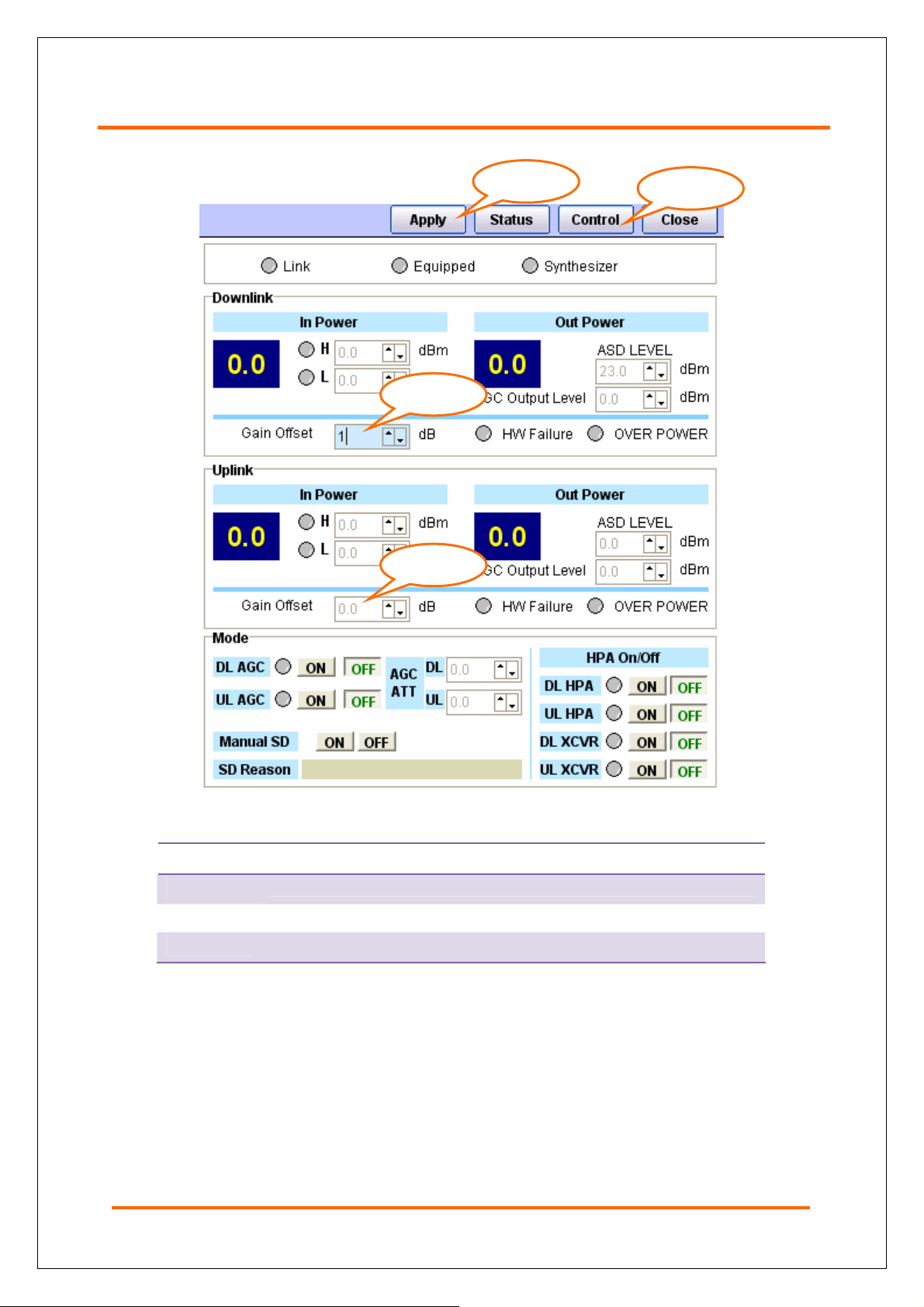
4.5.4 GAIN OFFSET
Step. 2
Step. 2
Step. 3
Step. 1
Figure 26 Gain Offset
STEP
1.
2.
3.
Click on “Control” to change mode to Control.
Enter a value (-3 dB ~ 3dB)
Click ‘Apply’.
38
Page 39

AROTA-VQ100™ User Manual
4.5.5 HPA ON/OFF
Step. 3
Step. 1
Step. 2-1
Step. 2-2
Figure 27 HPA ON/OFF
STEP
1.
2-1.
2-2.
3.
Click on “Control” to change mode to Control.
Click the ‘ON’ or ‘OFF’ button if you need to set DL of HPA ON or OFF.
Click the ‘ON’ or ‘OFF’ button if you need to set UL of HPA ON or OFF.
(*The green LED turns on when you set it ‘ON’.)
Click ‘Apply’.
39
Page 40

4.6.6 XCVR ON/OFF
Step. 1 Step. 3
Step. 2-1
Figure 28 XCVR ON/OFF
Step. 2-2
STEP
1.
2-1.
2-2.
3.
Click on “Control” to change mode to Control.
Click ON or OFF to change if you need to set DL of XCVR on or off.
Click ON or OFF to change if you need to set DL of XCVR on or off.
(*The green LED turns on when you set it ‘ON’.)
Click ‘Apply’.
40
Page 41

AROTA-VQ100™ User Manual
4.6.7 MANUAL Shut Down ON
Step. 1
Step. 2
Figure 29 Manual Shut Down On
STEP
1.
2.
When manual shutdown is on, DL HPA, UL HPA, DL XCVR and UL XCVR are all
changed to the ‘ON’ state.
Click on “Control” to change mode to Control.
Click the button to set it ‘ON’.
41
Page 42
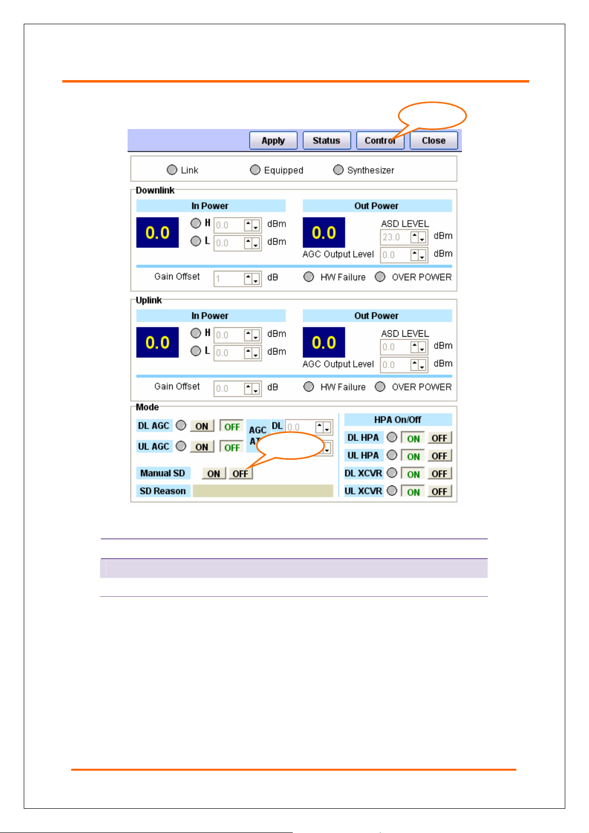
4.6.8 MANUAL Shut Down OFF
Step. 1
Step. 2
Figure 30 Manual Shut Down Off
STEP
1.
2.
Click on “Control” to change mode to Control.
Click the button to set it ‘ON’.
When manual shutdown is on, DL HPA, UL HPA, DL XCVR and UL XCVR are all
changed to the ‘ON’ state.
42
Page 43
AROTA-VQ100™ User Manual
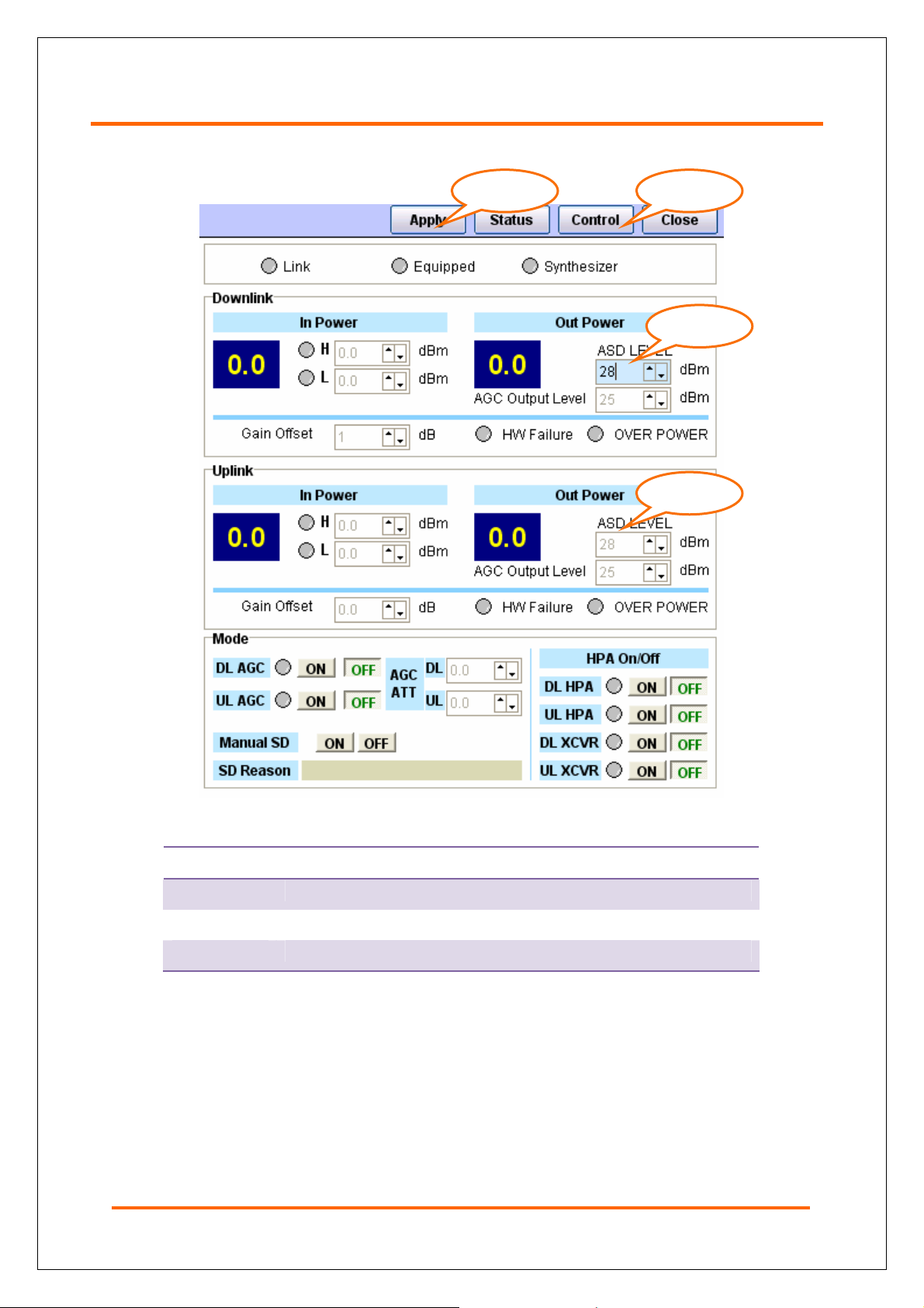
4.6.9 Automatic Shut Down
Step. 3 Step. 1
Step. 2
Step. 2
Figure 31 Setting Up ASD for Overpower
STEP
1.
2.
3.
Click on “Control” to change mode to Control.
Set ASD level.
Click ‘Apply’.
If there is any condition for shutdown, shutdown will be activated and the reason for
ASD will be displayed. (Oscillation Detected, Spurious Emission)
If the device is in permanent shutdown mode, reset the device or turn the manual
shutdown only after resolving the issue that caused shutdown.
2 dB Hysteresis needs to be met before shutdown is deactivated to prevent the unit
from ping-ponging between ON and OFF.
43
Page 44

4.6.10 FILTERS
- If you click each module, the section for setting a filter will be displayed as below.
1) PCS
Step. 3 Step. 1
Step. 2
Figure 32 Filter Selection
STEP
1.
2.
3.
Click on “Control” to change mode to Control.
Select desired band(s).
Click ‘Apply’.
44
Page 45
AROTA-VQ100™ User Manual
2) Cellular
3) LTE-C
4) LTE-A&B
45
Page 46

4.7 SUB Functions
Note. 1
Note. 2
Note. 3
Figure 33 Main Window (Sub Functions)
Note. Description
1
2
3
If you click ‘Download’, a pop-up will come on to upgrade a firmware of each
module and main board.
If you click ‘Debug’, a pop-up will come on to check the status of communication
link between GUI and main board.
If you click ‘Serial’ or ‘USB’ as a connection method of GUI and press ‘Port Open’,
communication will starts with main board.
46
Page 47

AROTA-VQ100™ User Manual
4.7.1 DOWNLOAD
4.7.1.1 Download Screen
It describes each function to upgrade a firmware in each module.
Note. 1
Note. 10
Note. 9
Note. 8
Note. 7
Note. 3 Note. 2
Note. 6
Note. 5 Note. 4
Figure 34 Download Screen
Note. Description
1
Select a module for downloading
47
2
3
4
5
6
7
8
9
10
The button to start downloading the selected binary file into the module
The button to stop downloading
Display the percentage of download progress
Display estimated time for finishing download.
Display time elapsed for download
Display filename of selected binary file.
Display downloading progress
Display Status
The button to choose a binary file to download
Page 48

4.7.1.2 Downloading
1. Download File Open
Step. 1
1.
2.
3.
Step. 2
Step. 3
Download File Open
STEP
Click “Download File Open”.
Select a file.
Press the ‘Open’ button.
48
Page 49

AROTA-VQ100™ User Manual
2. Download Start
Step. 1
Step. 2
1.
2.
Once you select a file, the download Start button will be active. If you click it, it will start
downloading.
It shows the file name of selected download file.
Description of downloading
progress
Note. 1
Download Start
STEP
Note. 2
49
Note. 3
Download Progress
Page 50

Note. Description
1
2
3
If you start downloading, the progress will be displayed in the ‘Status’ section..
If you want to stop downloading, press the ‘Download Stop’ button.
Elapsed time, estimated time and the percentage of progress to download are
displayed on the bottom status bar.
- If you click the ‘Download Stop’ button, the pop-up will be come out in below Figure..
Download stop message
- If download is completed, there will be appeared like below window.
Download Success message
50
Page 51

AROTA-VQ100™ User Manual
4.7.2 DEBUG
It is a screen to debug AIDs in communication link between GUI and main board.
Note. 3
Figure 35 Debug Screen
Note. Description
Note. 2 Note. 1
Note. 4
1
2
3
4
The checkbox which stops updating during communication
Delete all contents on the list.
The list which shows the packets between GUI and main board. If you click
some content, details about it are displayed as in section No 4.
The list which shows separated AID contents of the packet selected in No 3.
51
Page 52

5. Product Description
5.1 System Architecture
The system is designed to be installed in a standard 19” rack with easy handling,
assembly, and installation. For simple maintenance and configuration, the modules can be
inserted and removed from the front side without using any tool.
The system modules are shown below.
①
③ ④ ⑤ ⑥
Figure 36 Shelf Front Side Cards
Table 10 Modules on the Front of SHELF
Num Name Num Name
① Shelf ⑧ LTE A/B XCVR
② OMU ⑨ LTE A/B HPA
③ FEU ⑩ LTE C XCVR
④ PCS XCVR ⑪ LTE C HPA
⑤ PCS HPA ⑫ AWS XCVR
⑥ Cellular XCVR ⑬ AWS HPA
⑦ Cellular HPA
⑦ ⑧ ⑨ ⑩
②
⑪
⑫
⑬
52
Page 53

AROTA-VQ100™ User Manual
5.2 Product Views and Physical Dimensions
[View of top]
53
[View of front] [View of side]
[View of rear]
Figure 37 System Dimension
Page 54

Front Front Interior
Figure 38 Shelf: Front
On the back side of the shelf, 2-hole ground lug is equipped for 18㎟ ground cable.
Back Back Side Interior
54
Page 55

AROTA-VQ100™ User Manual
Figure 39 Shelf: Back Side
Top
Top
Figure 40 Shelf: Top Side
55
Page 56

Left Side Right Side
Figure 41 Shelf: Sides
56
Page 57

AROTA-VQ100™ User Manual
Bottom
Figure 42 Shelf: Bottom Side
5.3 Unit Description
The table below describes each modules in the system.
Table 11 Units
Num Unit Name Illustration Modules
1 Shelf
2 OMU
3 FEU
Chassis/Panels /Cables
MUX
Back Board Assembly
PSU
Alarm Monitoring Unit
Weight : 31.15Kg(Including FEU)
Housings/Panels /Cables
NMS board
Wireless Modem
Alarm LED
Fan
Weight : 1.44Kg
Housings/Panels/ Connectors/Cables
Couplers
Arrestor
57
Page 58

Num Unit Name Illustration Modules
Housings/Panels
4 PCS XCVR
RF Transceiver
DSP board
Weight : 2.79Kg
Housings/Panels
5 PCS HPA
HPA
Weight : 3.01Kg
Housings/Panels
6
Cellular
XCVR
RF Transceiver
DSP board
Weight : 2.82Kg
7 Cellular HPA
LTE A/B
8
XCVR
9 LTE A/B HPA
Housings/Panels
HPA
Weight : 2.83Kg
Housings/Panels
RF Transceiver
DSP board
Weight : 2.83Kg
Housings/Panels
HPA
Weight : 3.01Kg
58
Page 59

AROTA-VQ100™ User Manual
Num Unit Name Illustration Modules
Housings/Panels
10 LTE C XCVR
11 LTE C HPA
12 AWS XCVR TBD
13 AWS HPA TBD
Table 12 Power Consumption Per Unit
RF Transceiver
DSP board
Weight : 2.82Kg
Housings/Panels
HPA
Weight : 3.01Kg
Housings/Panels
RF Transceiver
DSP board
Weight : TBD
Housings/Panels
HPA
Weight : TBD
Item Currents Condition
Shelf 884 mA
PCS 1256 mA
Cellular 566 mA
LTE C 1016 mA
LTE AB 996 mA
Total Current 4718 mA
Power Consumption 518.98 W Input: AC110V
Max Gain.
59
Page 60

5.3.1 Shelf
Figure 43 Shelf Case
Figure 44 Shelf: Equipping Module Cards
60
Page 61

AROTA-VQ100™ User Manual
Figure 45 Shelf: Fully Equipped
5.3.1.1 PSU (Power Supply Unit)
The PSU supplies +29V, +12V, +6V and +4V to each modules by converting 110V AC.
The PSU also includes ON/OFF switch as well as a fuse to protect from a surge. LED for
status indication and monitoring port for DC output levels are provided.
Table 13 PSU Capacity
Output
Voltage
+29V 16A HPA
+12V 1.5A Wireless MODEM, FAN
+6V 23A RF Transceiver Board, Alarm Monitoring Unit,
+4 20A DSP Board
PSU and its pin maps are shown below.
Max.
Current
Usage Power
Consumption
700W
DSP Board, NMS, SNMP, LED Board
61
Page 62

외관도 PSU Location
I/O Voltage
INPUT AC110V
+29V
+12V
OUTPUT
+6V
Figure 46 PSU
Table 14 PSU Pin Map
Pin Map
Remarks
1. AC_L
2. AC_N
3. F.G
G: Ground
G : Ground
A : Alarm
G: Ground
+4
G: Ground
62
Page 63

AROTA-VQ100™ User Manual
5.3.1.2 MUX(Multiplexer)
MUX filters out the out of band signals. For the uplink, MUX filters out signals from HPA
to antenna so that the system would transmit any RF to other bands. For downlink, it
suppresses out of band signals other than air-coupled signals from the donor base stations.
The main function of Multiplexer and interface diagram between Arrester and
Coupler are as below.
63
Figure 47 MUX
Page 64

1. UL Multiplexer
- Consists of a block to multiplex RF signal in LTE A/B Band, LTE C-Band, and
Cellular Band and another Block to multiplex RF signals from PCS and AWS.
- Wireless MODEM Connection Port.
2. DL Multiplexer Block
- Multiplexes Cellular & PCS, LTE A/B, LTE C, and AWS Band.
5.3.1.3 Alarm Monitoring Unit
64
Page 65

AROTA-VQ100™ User Manual
Figure 48 Alarm Monitoring Unit
The unit includes various detection circuits that generate alarm and status monitoring
signals. A built-in OCXO module provides 10MHz reference signal. The Alarm
Monitoring Unit consists of two functional parts of alarm monitoring and generation and
distributing 10MHz reference signal.
1. Alarm Monitoring and Generation Part
Monitors the following items and issues alarms if it goes out of specifications.
- UL : Out-of-band emission out of spec
- DL : Low Isolation, Spurious emission out of spec, Interferer power exceeded
2. 10MHz Clock Distribution Part
Distributes 10MHz Reference Clock to XCVR.
5.3.1.4 Wireless Modem
65
Wireless Modem
Page 66

Figure 49 Wireless MODEM
The wireless modem installed is Sierra Wireless AirLinkTM Raven. The location of the
wireless modem is within OMU Unit as shown in Figure 49.
5.3.1.5 Back Board
The back board collects control and monitoring signals from the modules and sends them
to NMS. It also supplies DC power from PSU to each modules.
Front Back
66
Page 67

AROTA-VQ100™ User Manual
Front Back
Location Picture
Figure 50 Back Board
5.3.1.6 Ground
For grounding, 14SQ Copper connector is available on the back side of the shelf.
Figure 51 Ground Connector
67
Page 68

5.3.2 OMU(Operating and Management Unit)
Figure 52 OMU
OMU is responsible for monitoring and controlling the system as NMS. It connects to an
upper management system such as NOC using the installed wireless modem.
The physical connection with a PC is done via USB Port on the OMU. It also provides
RJ-45 port. For visual monitoring purposes LED’s are located on the front side of OMU.
OMU also houses 2 fans for cooling the system..
DEBUG : USB Connection with a PCS for NMS Control and GUI Connection.
GUI : Ethernet Port for an upper management system such as NOC. It can also be
used to access wireless modem with internally wired D-Sub 9-pin connector.
ALARM LED : The LED’s on the front side are described in the table below.
68
Page 69

AROTA-VQ100™ User Manual
Table 15 ALARM LED
Category Item Description
OSC
SD
TD Not used
GENERAL
DONOR
COVERAG
E
BITF
RMF
AGC
RESET
CF
DPTL
CF
5.3.3 FEU(Front End Unit)
: Normal
: Oscillation Alarm
: Normal
: Shut Down Alarm
: Normal
: Built-in Module Fail
: Normal
: Replaceable Module Fail
Toggle : AGC Status
: AGC OFF
: Normal
: RESET
: Normal
: Down Link Circuitry Fail
: Normal
: Down Link Power too low
: Normal
: Up Link Circuitry Fail
Figure 53 FEU
FEU is directly connected to antennas. It consists of an arrester, coupler, and EMI filter.
69
Page 70

5.3.4 XCVRs(Transceivers)
Figure 54 XCVR
5.3.5 HPAs(High Power Amplifiers)
Figure 55 HPA
70
Page 71

AROTA-VQ100™ User Manual
The HPA amplifies RF signal from the RF board to a maximum output power. The HPA
has a separate power switch for shutting it down in necessary.
The HPA unit houses both downlink and uplink amplifiers.
Table 16 HPA
Category Item Remarks
DL : Over Power Alarm, Shutdown Alarm,
LTE/CELL/
PCS
Alarm
Fault Detect
Connector
UL : Over Power Alarm, Shutdown Alarm,
DL Fault Alarm, UL Fault Alarm
Alarm Generation for Abnormal HW condition
- Detect : Temperature Sensing + Current
Sensing
RF : Trumpet (Male)
Power and Digital : D_Sub 9Pin (Male)
71
Page 72

6 System Specifications
6.1 General Specifications
6.1.1 Tx/Rx Frequencies
6.1.1.1 LTE
6.1.1.2 Cellular
6.1.1.3 PCS
72
Page 73

AROTA-VQ100™ User Manual
6.1.2 General Specifications
Category Specifications Remarks
Antenna Port
Carrier
Composite Output
Power
Local GUI Interface RJ-45
Debug Port USB
Characteristic
Impedance
Donor ANT Port : 2 (LTE & Cellular, PCS & AWS)
Coverage ANT Port : 1 (Quad Band)
LTE : 1x10MHz and 2x5MHz
Cellular : 15 Continuous Carrier in A1-A2 & B1-B2
PCS : 15 Continuous Carrier in 20MHz
AWS : TBD
LTE : 27dBm @ANT Port
Cellular : 25dBm @ANT Port
PCS : 30dBm @ANT Port
50 ohm
Total Carrier
6.2 Electrical Specifications
6.2.1 Cellular
6.2.1.1 DL & UL Common Specifications
Category Specification Remarks
System Time Delay
Gain Offset
AGC Dynamic Range 30dB
AGC Error/Control Step Reference ± 2.0 dB/1dB Step
6.2.1.2
Output Power/Tolerance 25dBm @ANT Port/±2dB Max.
Input Power Range -60dBm ~ -30dBm @ANT Port
Gain Control Range 55 ~ 85dB
Flatness 5dB p-p Max.
Out-of-Band
Rejection
Spurious Emission Limit -13dBm/1KHz @9KHz~150KHz Total Carrier,
DL Specifications
Category Specification Remarks
Sub-band
Selectivity
A2 Band Rejection 30dBc Min. @890.25MHz & 891.25MHz
Max. 6㎲ @each filter
3dB
45dBc Min @±1.5MHz from each cellular sub-
band edge
Out-of-Band
Rejection
73
Page 74

Category Specification Remarks
-13dBm/10KHz @150KHz~30MHz
-13dBm/100KHz @30MHz~1GHz
-13dBm/1MHz @1GHz~12.75GHz
ITU Category A
Noise Figure.
EVM
1x 17.5% Max
EVDO 14.75% Max.
7.0dB 이하 @Max Gain & each freq block
6.2.1.3 UL Specifications
Category Specification Remarks
Output Power/Tolerance 25dBm @ANT Port/±2dB Max.
Input Power Range -60dBm ~ -30dBm @ANT Port
Gain Control Range 55 ~ 85dB
Flatness 5dB p-p Max.
Out-of-band
Rejection
Spurious Emission Limit
Noise Figure. 7.0dB Max. @ Max Gain & each freq block
EVM
Sub-band
selection
A2 Band Rejection 30dBc Min. @845.25MHz & 846.25MHz
1x 17.5% Max
EVDO 17.5% Max
45dBc Min. @±1.5MHz from each cellular
sub-band edge
-13dBm/1KHz @9KHz~150KHz
-13dBm/10KHz @150KHz~30MHz
-13dBm/100KHz @30MHz~1GHz
-13dBm/1MHz @1GHz~12.75GHz
6.2.2 PCS
6.2.2.1 DL & UL Common Specifications
Category Specification Remarks
Out-of-band
Rejection
Total Carrier,
ITU Category A
System Time Delay
Gain Offset
AGC Dynamic Range 30dB
AGC Error/Control Step Reference ± 2.0 dB/1dB Step
6㎲ Max. @each filter
3dB
6.2.2.2 DL Specifications
Category Specification Remarks
Output Power/Tolerance 30dBm @ANT Port/±2.0dB Max.
Input Power Range -70dBm ~ -40dBm @ANT Port
Gain Control Range 70 ~ 100dB
Flatness 5dB p-p Max.
Out-of-Band Rejection
45dBc Min. @±2.0MHz from each PCS sub-
band edge
Sub-band
selectivity
74
Page 75
AROTA-VQ100™ User Manual
Category Specification Remarks
-13dBm/1KHz @9KHz~150KHz
Spurious Emission Limit
Noise Figure. 7.0dB Max. @Max Gain & each freq block
EVM
1x 17.5% Max
EVDO 14.75% Max.
-13dBm/10KHz @150KHz~30MHz
-13dBm/100KHz @30MHz~1GHz
-13dBm/1MHz @1GHz~12.75GHz
6.2.2.3 UL Specifications
Category Specification Remarks
Output Power/Tolerance 30dBm @ANT Port±2.0dB Max.
Input Power Range -70dBm ~ -40dBm @ANT Port
Gain Control Range 70 ~ 100dB
Flatness 5dB p-p Max.
Out-of-Band Rejection
Spurious Emission Limit
Noise Figure. 7.0dB Max. @ Max Gain & each freq block
EVM
1x 17.5% Max
EVDO 17.5% Max
45dBc Min. @±2.0MHz from each PCS sub-
band edge
-13dBm/1KHz @9KHz~150KHz
-13dBm/10KHz @150KHz~30MHz
-13dBm/100KHz @30MHz~1GHz
-13dBm/1MHz @1GHz~12.75GHz
Total Carrier,
ITU Category A
Sub-band
selectivity
Total Carrier,
ITU Category A
6.2.3 LTE
6.2.3.1 DL & UL Common Specifications
Category Specification Remarks
System Time Delay
Uplink Gain Offset -2dB relative to the downlink gain
AGC Dynamic Range 30dB
AGC Error/Control Step Reference ± 2.0 dB/1dB Step
6.2.3.2 DL Specifications
Category Specification Remarks
Output Power/Tolerance 27dBm @ANT Port/±2dB Max.
Input Power Range -66dBm ~ -36dBm @ANT Port
Gain Control Range 63 ~ 93dB
Flatness 1dB p-p Max.
Out-of-Band Rejection 45dBc Min. @±1MHz from each LTE sub-
6㎲ Max. @each filter
Sub-band Selectivity
75
Page 76

Category Specification Remarks
band edge
-13dBm/1KHz @9KHz~150KHz
-13dBm/10KHz @150KHz~30MHz
Spurious Emission Limit
Noise Figure. 7.0dB Max. @Max Gain & each freq block
-46dBm/6.5KHz @763MHz~775MHz
-13dBm/100KHz @30MHz~1GHz
-13dBm/1MHz @1GHz~12.75GHz
EVM 12.5% Max.
6.2.3.3 UL Specifications
Category Specification Remarks
Output Power/Tolerance 27dBm @ANT Port/±2dB Max.
Input Power Range -66dBm ~ -36dBm @ANT Port
Gain Control Range 63 ~ 93dB
Flatness 1dB p-p Max.
Out-of-Band Rejection
Spurious Emission Limit
Noise Figure. 7.0dB Max. @Max Gain & each freq block
EVM 17.5% Max.
45dBc Min. @±1MHz from each LTE sub-
band edge
-13dBm/1KHz @9KHz~150KHz
-13dBm/10KHz @150KHz~30MHz
-46dBm/6.5KHz @793MHz~805MHz
-13dBm/100KHz @30MHz~1GHz
-13dBm/1MHz @1GHz~12.75GHz\
Sub-band selectivity
76
Page 77

AROTA-VQ100™ User Manual
6.3 LED & Alarm Specifications
Category Specification Remarks
LED
Alarm
Tamper detected
Built-in test failure
Replaceable module failure
General
AGC active
Reset engaged
Oscillation detected
Shutdown
Donor Issues
Circuitry failure
Donor power too low
Coverage Issues Circuitry failure
Tamper detected
Power supply out of range
Communication failure
General
Field replaceable module failure
Reset alarm
Manual shutdown alarm
Heartbeat
Oscillation detected
Power at coverage port too high
Uplink
Synthesizer failure
Hardware failure
Software failure
Out of band emission of spec
Donor power too high/low
Low isolation
Synthesizer failure
Downlink
Hardware failure
Software failure
Spurious emission out of spec
Interferer power exceeded
77
Page 78

6.4 Mechanical and Environmental Specification
6.4.1 Mechanical Specifications
Category Specification Remarks
Installation Indoor
Cooling Forced Convection (FAN)
Shelf Size
Weight 61kg(Fully equipped except for AWS)
RF Connector
Ethernet Port RJ45 GUI Port
Power Connector Circular Type (3pin)
6.4.2 Environmental
Category Specification Remarks
Temperature Operational Temperature : -5~50OC
19” Rack Mount,
Height (8U), Depth (559mm)
Donor ANT Port : N(Female) – 2port
Coverage ANT Port : N(Female) – 1port
Monitor Port : SMA(Female) – 3port
Monitoring Port : 30dB2dB
Humidity 40% relative humidity at 50OC
waterproof IP40
78
Page 79

AROTA-VQ100™ User Manual
7 Troubleshooting
7.1 General
Power supply out of range
Cause : Faulty Main Power Supply
Remedy : Check Input AC power. If AC Power is ok, replace PSU.
Field replaceable Module fail
Cause : Issues with XCVR or HPA
Remedy : Check which band is having trouble from GUI.
Turn off HPA Power Switch and Replace the HPA.
Replace XCVR if alarm persists after HPA replacement.
7.2 Downlink
Donor Power too high/low
Cause : Input Power level to donor antenna is too high.
Remedy : Check input power level to donor and thresholds for alarm for proper
threshold setting.
Check all connectors to/from donor antenna.
Check donor base-station is operating normally.
Low Isolation
Cause : Low Isolation between Donor Antenna and Service Antenna
Remedy : Reseat XCVR and HPA. Make sure captive panel screw is well tightened.
Check for unintended changes in donor or coverage antenna.
Adjust Antennas for good isolation between Donor and Service Ant.
Synthesizer Failure
Cause : Faulty Frequency Synthesizer.
Remedy : Check Sysnthesizer from which band is issuing the alarm.
Replace the XCVR.
If alarms are on for all XCVR, replace the shelf.
Hardware Failure
Cause : Faulty PSU or Alarm Monitoring unit
Remedy : Replace Shelf
79
Page 80

Software Failure
Cause : Software Download Failure
Remedy : SW Reboot
Download Software again.
Replace the shelf.
Spurious emissions out of spec
Cause : Spurious emissions exceed FCC limit
Remedy : Check for any failure for each band.
Repleace HPA for the band in alarm
Replace shelf if HPA replacement does not remove the alarm.
Interferer power exceeded
Cause : Interference level is too high.
Remedy : Confirm interference by connecting spectrum analyzer to monitoing port of
FEU. Identify and remove interference source.
7.3 Uplink
Oscillation Detected
Cause : Low Isolation between Donor Antenna and Service Antenna
Remedy : Reseat XCVR and HPA. Make sure captive panel screw is well tightened.
Check for unintended changes in donor or coverage antenna.
Adjust Antennas for good isolation between Donor and Service Ant.
Power at coverage port too high
Cause : Input power to coverage antenna is too high Oscillation detected
Remedy : From GUI, check if Uplink Input Power Upper Threshold value is set at a
proper level.
Consider re-locating coverage antenna.
Please refer to troubleshooting guide for Oscillation Dectected.
Synthesizer Failure
Cause : Faulty Frequency Synthesizer.
Remedy : Check Sysnthesizer from which band is issuing the alarm.
Replace the XCVR.
If alarms are on for all XCVR, replace the shelf.
Hardware Failure
Cause : Faulty PSU or Alarm Monitoring unit
Remedy : Replace Shelf
80
Page 81

AROTA-VQ100™ User Manual
Software Failure
Cause : Software Download Failure
Remedy : SW Reboot
Download Software again.
Replace the shelf.
Out of band emissions out of spec
Cause : Out of Band emission level exceeds the specification around service band.
Remedy : From GUI, check which band is at fault.
Replace XCVR with alarm
81
Page 82

8 Glossaries
ACLR : Adjacent Channel Leakage Ratio
AGC : Automatic Gain Control
ASD : Automatic Shut Down
ATT : Attenuation
B/D : Board
BITF : Built-In Test Failure
CF : Communication Failure
CRC : Cyclic Redundancy Check
CW : Continuous Wave
DC : Direct Current
DL : Down Link
DPTL : Donor Power Too Low
EVM : Error Vector Magnitude
FEU : Front End Unit
FW : Firm Ware
GUI : Graphic User Interface
H/W : Hardware
HPA : High Power Amplifier
MUX : Multiplexer
NOC : Network Operating Center
OMU : Operating and Management Unit
OSC : Oscillation
PA : Power Amplifier
PD : Photo Diode
PSU : Power Supply Unit
PWR : Power
RF : Radio Frequency
RMF : Replaceable Module Failure
RX : Receiver
S/W : Switch
SD : Shut Down
SNMP : Simple Network Management Protocol
TD : Tamper detected
TX : Transmitter
UL : Up Link
Ver : Version
XCVR : Transceiver
82
Page 83

p
T
S
i
v
o
i
v
M
M
n
a
ThePre
ention
eansofS
turation
Ap
end
x
he
Pre
ent
on
ea
s o
f
atu
rati
n
- 1 -
Page 84

v
c
p
.2.
h
h
i
a
d
O
n
-
-
-
-
A
m
d
t
e
s
n
t
A
m
v
o
o
p
b
k
P
v
d
u
r
m
m
m
m
u
l
v
n
d
d
9 9 8
0
v
f
l
e
n
O
M
t
C
e
D
x
e
r
a
a
p
r
w
o
a
C
m
D
0302833
r
r
r
o
l
r
.
D
ThePre
ention
eansofS
turation
1. O
2. O
This
oper
devi
2
erview
device
ation. W
e protect
eration
1 Linear
It is
operat
maxim
as an
en satura
on and
Operatio
possible
ion. The
um input
SD(Auto
tion or o
ake spuri
n Range
range f
evice ap
power in
atic Sh
er-modu
us emissi
r the de
lies AGC
elow tab
tDown)
ation occ
on not to
ice to o
so that
le.
unction
urs, ASD
exceed F
perarte n
inear op
o maint
will be a
C standa
ormally
ration w
in linea
plied fo
d.
ith linea
rks up t
Band
LTE AB
LTE C
Cellular
PCS
2 Satura
When
such a
device
Accor
operat
Input
(Linear
Ra
Under
Under
Under
Under
tion Poin
linear op
s pulsed
protectio
ingly, Sa
ing. The
Power
peration
ge)
36dBm
36dBm
30dBm
40dBm
ration is
ignal that
and ma
uration
SD level
Rate
Outp
Powe
27dB
27dB
25dB
30dB
out of ra
is entere
e spuriou
oint is
alues are
t
1
ge, caus
to the d
s emissio
efined a
shown be
Ma
x Gain
3dB
3dB
5dB
0dB
d by ove
evice, AS
not to e
s ASD l
low.
ver Powe
Alarm
29dBm
29dBm
27dBm
32dBm
rpower in
will be
ceed FC
vel to
AS
(Sat
put signa
pplied fo
standard
ake AS
Level
uration
P
oint)
3
dBm
dBm
dBm
dBm
- 2 -
Page 85

S
.
.
m
A
p
3
o
e
n
.
a
D
h
o
r
n
o
o
n
E
)
o
s
t
s
a
o
t
s
m
w
O
o
v
n
a
b
M
C
e
t
e
a
s
s
s
d
ThePre
ention
eansofS
turation
3. A
D(Auto
3
1 ASD
When
will be
arises
conditi
At this
device,
atic Sh
lgorithm
ower out
operating
times, c
n, it goes
time, if y
it will be c
utDown
of range
within 4
eck again
permanen
u control
leared.
Opera
r spuriou
econds an
after 30
ly shutdo
the On/
ion
emission
d recheck
inutes. In
n.
ff, reset a
exceeds F
after 10 s
this case,
d manual
C limits,
conds. If
if it is in
shutdown
hutdown
hutdown
hutdown
parts of
3
2 Notic
During
checki
service
and st
※
AS
-
-
e-checki
g values
If ASD c
rt to reche
conditio
Oscillatio
Spurious
g proces
f ASD par
ndition is
ck.
n
mission
, if ASD
meter sh
satisfied a
ut of FCC
condition
uld be cle
gain, go
limit
is not sa
ed and t
ack to th
isfied, all
hen provi
first chec
previous
e normal
king step
- 3 -
 Loading...