


ART TUBEOPTO8 User manual

Tubeopto 8™
8-CHANNEL TUBE MICROPHONE
PREAMPLIFIER / OPTICAL INTERFACE
USER’S GUIDE

IMPORTANT
alerts you to the presence of uninsulated you to important operating and maintenance
dangerous voltage inside the enclosure. Voltage instructions in the accompanying literature.
that may be sufficient to constitute a risk of shock. Please read manual.
Read instructions:
Retain these safety and operating instructions for future reference. Heed all warnings printed here and on the equipment.
Follow the operating instructions printed in this user guide.
Do not open:
Aside from four vacuum tubes, there are no user serviceable parts inside. Refer any service work to qualified technical
personnel only.
Power sources:
Only connect the unit to mains power of the type marked on the rear panel. The power source must provide a good
ground connection.
Power cord:
Use the power cord with sealed mains plug appropriate for your local mains supply as provided with the equipment. If the
provided plug does not fit into your outlet consult your service agent. Route the power cord so that it is not likely to be
walked on, stretched or pinched by items placed upon or against.
Grounding:
Do not defeat the grounding and polarization means of the power cord plug. Do not remove or tamper with the ground
connection on the power cord.
Ventilation:
Do not obstruct ventilation or position the unit where the air required for ventilation is impeded. If the unit is to be operated
in a rack, case or other furniture, ensure that it is constructed to allow adequate ventilation.
Moisture:
To reduce the risk of fire or electrical shock do not expose the unit to rain, moisture or use in damp or wet conditions. Do
not place a container of liquid on it, which may spill into any openings.
Heat:
Do not locate the unit in a place close to excessive heat or direct sunlight, as this could be a fire hazard. Locate the unit
away from any equipment, which produces heat such as: power supplies, power amplifiers and heaters.
Environment:
Protect from excessive dirt, dust, heat, and vibration when operating and storing. Avoid tobacco ash, drink spillage and
smoke, especially that associated with smoke machines.
Handling:
To prevent damage to the controls and cosmetics avoid rough handling and excessive vibration. Protect the controls from
damage during transit. Use adequate padding if you need to ship the unit. To avoid injury to yourself or damage to the
equipment take care when lifting, moving or carrying the unit.
Servicing:
Switch off the equipment and unplug the power cord immediately if it is exposed to moisture, spilled liquid, objects fallen
into opening, or the power cord or plug becomes damaged during a lightning storm or if smoke odor or noise is noted.
Refer servicing to qualified technical personnel only.
Installation:
Install the unit in accordance with the instructions printed in the user guide.
II
This symbol, wherever it appears, This symbol, wherever it appears, alerts
SAFETY INSTRUCTIONS – READ FIRST

The ART Tubeopto 8™
8-Channel Tube Microphone Preamplifier Optical Interface
IMPORTANT SAFETY INSTRUCTIONS – READ FIRST .............................................. II
INTRODUCTION.......................................................................................................... 1
INSTALLATION...........................................................................................................1
AC Power Hookup..................................................................................................................................................................................1
Analog Audio Connections .....................................................................................................................................................................1
CONTROLS and JACKS..............................................................................................2
FRONT PANEL......................................................................................................................................................................................2
Instrument Input ..................................................................................................................................................................................... 2
Gain Control...........................................................................................................................................................................................2
Pad Switch .............................................................................................................................................................................................2
+48V Switches........................................................................................................................................................................................3
Phase Switch..........................................................................................................................................................................................3
Low Cut Switch.......................................................................................................................................................................................3
LED Meter..............................................................................................................................................................................................3
Output Control........................................................................................................................................................................................3
Sample Rate/Sync Switch......................................................................................................................................................................3
Sample Rate LEDs.................................................................................................................................................................................4
Power Switch..........................................................................................................................................................................................4
REAR PANEL.........................................................................................................................................................................................4
Balanced Input Jacks – XLR & 1/4” TRS Combo Jacks.........................................................................................................................4
Balanced Output Jacks...........................................................................................................................................................................4
Output Level Switch ...............................................................................................................................................................................4
Wordclock Input and Thru Jacks............................................................................................................................................................5
ADAT Jacks............................................................................................................................................................................................5
HARDWARE OPERATION............................................................................................6
How to adjust the preamplifier controls for the lowest noise...................................................................................................................6
How to set the Output Level switch (on the rear panel)..........................................................................................................................6
Changing the sample rate ......................................................................................................................................................................6
Using the wordclock input.......................................................................................................................................................................7
APPLICATIONS...........................................................................................................8
Typical applications................................................................................................................................................................................8
Troubleshooting......................................................................................................................................................................................9
SERVICE...................................................................................................................11
Tubeopto 8™ SPECIFICATIONS ...............................................................................12
List of Figures
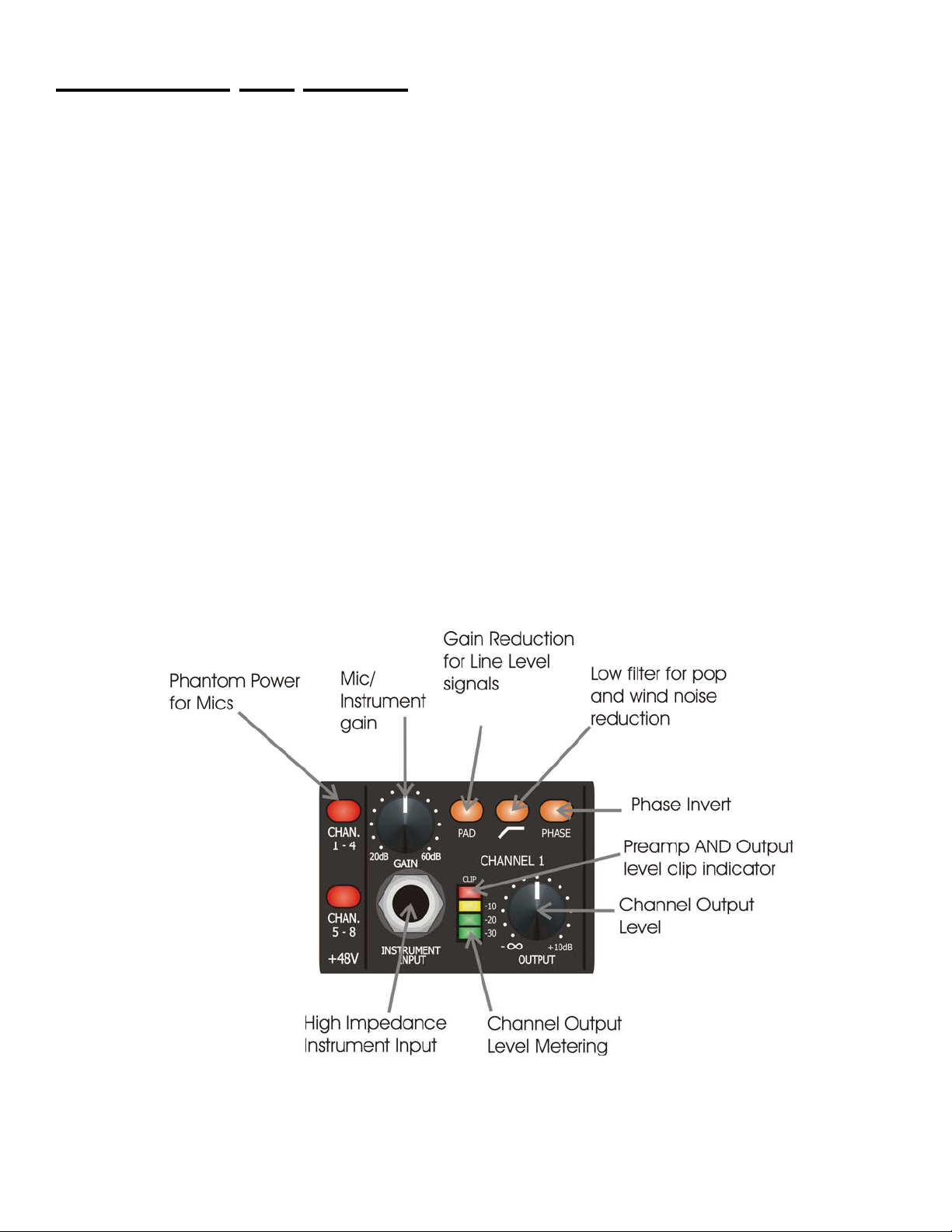
FIGURE 1 - Input Channel....................................................................................................................................2
FIGURE 2 - Sample Rate Section........................................................................................................................3
FIGURE 3 - Rear Panel........................................................................................................................................4
FIGURE 4 - Block Diagram...................................................................................................................................5
FIGURE 5 - Wordclock Connections....................................................................................................................7
III

INTRODUCTION
The Tubeopto 8™ is the ideal Eight Channel input/output expander for any ADAT Lightpipe equipped audio
interface, direct-to-disc recorder or DAW. Eight high quality second-generation discrete class–A vacuum tube
microphone preamps are packaged in a single rack space unit with eight channel 24-bit digital I/O. The mic
preamps drive internal high quality A/D converters and a standard ADAT Lightpipe digital interface. ADAT
digital input is coupled to internal high quality D/A converters that drive eight balanced 1/4” outputs.
Every input on the Tubeopto 8™ offers full control of the signal path with pad, phase and low frequency rolloff switches. Input gain and variable output level control of each channel allows up to 70dB of clean gain with
incredible sonic transparency and the tube stage can be dialed in for warming effects and soft clipping. Each
channel has wide range LED meters that monitor the preamp output levels to the A/D while clip indicators
monitor preamplifier peak levels. Balanced 1/4" phone or XLR inputs are available on each channel and high
impedance 1/4” instrument inputs are available on channels 1 and 2.
ADAT Lightpipe I/O handles eight channels of 24-bit audio input and output at 44.1KHz, 48KHz, or externally
set sample rates. Wordclock in and thru-puts allow multiple Tubeopto 8’s to be synced in complex system
configurations.
INSTALLATION
The Tubeopto 8™ may be used in a wide variety of applications and environments. In a rack-mountable, allsteel enclosure, the unit is designed for continuous professional use. Mounting location is not critical. However,
for greater performance reliability we recommend that you not place the unit on top of power amps or other
sources of heat, or strong magnetic fields. The tube circuitry needs about a minute to “warm up” and stabilize
from a cold power up.
AC Power Hookup
The Tubeopto 8™ has an internal power supply. Only connect the unit to mains power of the type marked on
the rear panel. The power source must provide a good ground connection, and the ground pin on the mains
plug should never be defeated.
Analog Audio Connections
Audio connections to and from the Tubeopto 8™ are:
Rear balanced combo input: [XLR] Pin 2 = Hot (+), Pin 3 = Cold (-), Pin 1 = Ground
[1/4”] Tip = Hot (+), Ring = Cold (-), Sleeve = Ground
Rear balanced 1/4” output: Tip = Hot (+), Ring = Cold (-), Sleeve = Ground
Front 1/4” instrument input: Tip = Hot (+), Ring = Cold (-), Sleeve = Ground
CONTROLS and JACKS
FRONT PANEL
Instrument Input
The 1/4” TS jack on the front panel provides a high impedance unbalanced input, and when used,
automatically switches off the mic pre-amp section. (The rear combo jack’s 1/4” TRS balanced input is lower
impedance and is part of the mic pre-amp. The rear jack is not intended to be used with high impedance
microphones or instruments.) NOTE: The PAD switch is disabled and DOES NOT affect gain when using the
Instrument input.
Gain Control
This control adjusts both the mic pre-amp gain as well as the instrument input gain. The gain markings apply
to the mic pre-amp without the Pad switch depressed. (The instrument input gain is lower than the markings.)
Please refer to the HARDWARE OPERATION section to learn how to optimize the gain control for low noise
operation.
Pad Switch
This switch reduces the mic pre-amp gain to prevent clipping when high-level microphone or line level signals
are applied to the rear panel XLR / 1/4” TRS combo jack input. This switch does NOT affect the instrument
input.
FIGURE 1 - Input Channel
2