

Page 1
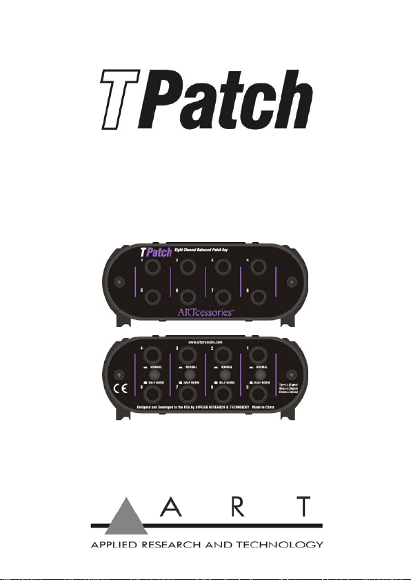
Eight Point Balanced Patch Bay
Artcessories
User's Manual
Page 2

IMPORTANT SAFETY INSTRUCTION – READ FIRST
This symbol, whenever it appears,
alerts you to the presence of
uninsulated dangerous voltage
inside enclosure-voltage that may be
sufficient to constitute risk of shock.
Read Instructions: Retain safety and operating instructions for
future reference. Heed all warnings printed here and on the
equipment. Follow the operating instructions printed in this us er
guide.
Do not open: There are no user serviceable parts inside. Refer
any service work to qualified technical personnel only.
Grounding: Only connect the unit to equipment with properly
grounded mains power. Do not defeat the grounding and
polarization means of the power cord plug of the connected
equipment. Do not remove or tamper with the ground
connection on the power cord of the connected equipment.
Environment: Protect from excessive dirt, dust, heat, and
vibration when operating and stori ng. Avoid tobacco as h, drink
spillage and smoke, especially that associated with smoke
machines.
Handling: Protect the controls from damage during trans i t. Us e
adequate padding if you need to ship the unit. To avoid injury to
yourself or damage to the equipment, take care when lifting,
moving or carrying the unit.
Servicing: Refer servicing to qualified technical personnel.
This symbol, whenever it appears,
alerts you to important operating
and maintenance instructions in
the accompanying literature.
Please read the manual.
Page 3

Installation: Install the uni t in accordance with the instructions
printed in the user guide.
Page 4

INTRODUCTION:
Thanks for purchasing Applied Research and
Technology’s TPatch. The ART TPatch Eight Point
Balanced Patch Bay is a deceptively simple, yet
surprisingly useful addition to any serious collection of
audio equipment.
A patch bay organizes your cables and provides a
convenient, easily accessible central location to make all
of your audio connections.
It also saves wear and tear on the connectors of your
audio equipment because all connections are now made
and changed at your patch bay.
Application settings include use in professional or home
recording studios, installed audio including PA, AV and
home theater, and live sound.
The compact black-anodized all aluminum case and it’s
passive design allow the TPatch to provide years of
trouble free service. It’s full feature set and rugged
construction make the ART TPatch the obvious choice.
Page 5

FEATURES:
• Eight points of balanced direct signals
• Four channels of linked input/output pairs
• Switchable half normal and normal modes of
operation (with through type connections)
• 1/4" TRS phone jack connectors
• Rugged extruded aluminum case
Page 6

A B C D
Page 7

USING A PATCH BAY:
Although the ART TPatch, like all patch bays, is
conceptually a simple device, there is a lot in the
terminology and usage conventions that can potentially
cause confusion. Each vertical grouping of two jacks on
the front of the unit and the corresponding two jacks and
switch on the rear of the unit comprise a module and
provides one channel of linked input/output audio
connections. For example, the jacks labeled 1 and 5 on
the front panel and the jacks labeled 1 and 5 on the rear
panel, along with the associated switch, are one
module. All four modules are identical and each may be
individually configured for Half Normal or Normal
operation. Read on to find out what this means.
INPUT OUTPUT
OUTPUT INPUT
Page 8

All connections start at the rear of the unit. By
convention, the top jacks are inputs and are connected
to audio sources or sends and the bottom jacks are
outputs and are connected to audio destinations or
receives (see left diagram above). With no connections
at the front of the unit, the vertical pair of rear panel
jacks are connected together internally. An audio signal
will flow from the top jack to the bottom jack without any
patch cords plugged in at the front in what is known as a
normalled connection, shown in case A in the Half
Normal and Normal diagrams above.
So far we've connected audio outputs to audio inputs,
which we could have done with just cables. But using
the jacks on the front of the unit is when things get
interesting. The convention on the front of a patch bay is
that the top jacks are outputs and the bottom jacks are
inputs (see right diagram above). This is just the
opposite of the rear connections, but makes sense if you
think of signals flowing through the patch bay.
With the rear panel pushbutton in the out position (Half
Norm), the Half Normal mode is selected (refer to the
Half Normal diagram above). This is the patch bay mode
most commonly used. In this mode we can plug a cable
into the top jack and take out or monitor the signal
flowing through the rear jacks by sending it to an
amplifier input or a set of headphones. This is shown in
case B. However, if we plug a cable into the bottom
jack, we break the connection between the rear jacks.
Thus we can put in or patch a signal that replaces the
Page 9

signal coming into the top rear jack, as shown in case C.
Finally, we can plug into both front jacks and get two
independent through signal paths where the original
source goes to a new destination and the original
destination gets a new source as shown in case D.
With the rear panel pushbutton pushed in (Normal), the
Normal mode is selected (refer to the Normal diagram
above). If you compare the two mode diagrams, you'll
notice that they're pretty similar. Only case B is different.
Now plugging a cable into the top jack breaks the
connection between the rear jacks just like plugging a
cable into the bottom jack does. Plugging a cable into
either (or both) jack(s) breaks the normalled connection.
All other aspects of the Normal mode are the same as
for the Half Normal mode.
A normalled connection is desirable for many
applications, but not all. For example, be careful not to
connect a signal processor's output and input to the
same module. Here a normalled connection would
create a feedback loop which is definitely not what you
want. Instead, use two separate modules, one for the
output and one for the input.
Page 10

SPECIFICATIONS:
Connectors: 1/4" TRS balanced
phone jacks
CMRR: > -90 dB (typical)
Isolation: > -80 dB (typical)
Dimensions HxWxD (in): 1.85 x 4.6 x 3.9
HxWxD (mm): 47 x 117 x 99
Weight ( lbs/kg): 0.84 / 0.38
Page 11

WARRANTY INFORMATION:
Limited Warranty (USA only)
Applied Research and Technology will provide warranty
and service for this unit in accordance with the following
warrants:
Applied Research and Technology, (ART) warrants to
the original purchaser that this product and the
components thereof will be free from defects in
workmanship and materials for a period of three years
from the date of purchase. Applied Research and
Technology will, without charge, repair or replace, at its
option, defective product or component parts upon
prepaid delivery to the factory service department or
authorized service center, accompanied by proof of
purchase date in the form of a valid sales receipt.
Exclusions
This warranty does not apply in the event of misuse or
abuse of the product or as a result of unauthorized
alterations or repairs. This warranty is void if the serial
number is altered, defac ed, or remov ed.
ART reserves the right to make changes in design or
make additions to or improvements upon this product
without any obligation to install the same on products
previously manufactured.
ART shall not be liable for any consequential damages,
including without limitation damages resulting from loss
of use. Some states do not allow limitations of incidental
Page 12

or consequential damages, so the above limitation or
exclusion may not apply to you. This warranty gives you
specific rights and you may have other rights, which
vary, from state to state. The warranty terms listed
above are only valid within the United States of America.
For units purchased outside the United States, an
authorized distributor of Applied Research and
Technology will provide service. For information on
warranty and service policies outside of the U.S., please
contact your local distributor.
Please fill in the following information for your reference:
Date of purchase: _________________________
Purchased from: _________________________
Page 13

SERVICE:
The following information is provided in the unlikely
event that your unit requires service.
1. Be sure that the unit is the cause of the problem.
Check to make sure that the unit has power
supplied, that all cables are connected correctly,
and that the cables themselves are in working
condition. You may want to consult with your dealer
for assistance in troubleshooting or testing your
particular configuration.
2. If you believe that the ART unit is at fault, go to
www.artproaudio.com. Select "Support", then
"Return Authorization Request" to request a return
authorization number.
3. If you are returning the unit for service, pack the
unit in its original carton or a reasonable substitute.
The original packaging may not be suitable as a
shipping carton, so consider putting the packaged
unit in another box for shipping. Print the RA
number clearly on the outside of the shipping box.
Print your return shipping address on the outside of
the box.
4. Include with your unit: a note with the RA number
and your contact information, including a return
shipping address (we cannot ship to a P.O. box)
and a daytime phone number, and a description of
the problem, preferably attached to the top of the
unit. Also include a copy of your purchase receipt.
 Loading...