

Page 1

APPLIED RESEARCH AND TECHNOLOGY
SERVICE MANUAL
STOMPWATCH
www.artproaudio.com
E-mail: support@artproaudio.com
© 2016 Applied Research & Technology • Yorkville Sound
RM5
SMT Disclaimer
Due to the complex nature of the use of SMT installed components
in Yorkville equipment, we highly caution all service technicians in
attempting to repair or replace SMT factory installed components.
Printed in Canada
Printed in Canada
Many of these components may be glued prior to initial soldering.
Replacing SMT components requires expensive
specialized de-soldering equipment and training.
Yorkville Sound will repair and replace defective SMT components
to ensure proper quality assurance and installation is maintained.
Manual-Service-ART-RM5-00-1v0 • August 20, 2018
Page 2
This lightning flash with arrowhead symbol, within
an equilateral triangle, is intended to alert the user to the presence of
uninsulated “dangerous voltage” within the product’s enclosure that may be
Ce symbole d’éclair avec tête de flèche dans un triangle équilatéral est prévu pour alerter
l’utilisateur de la présence d’un «voltage dangereux» non-isolé à proximité de l’enceinte du
produit qui pourrait être d’ampleur suffisante pour présenter un risque de choque électrique.
of sufficient magnitude to constitute a risk of electric shock to persons.
FOLLOW ALL INSTRUCTIONS SUIVEZ TOUTES LES INSTRUCTIONS
IMPORTANT SAFETY INSTRUCTIONS
CAUTION: HOT SURFACE
ATTENTION: SURFACE CHAUDE
IEC 60417-5041
Instructions pertaining to a risk of fire, electric shock, or injury to a person
CAUTION: TO REDUCE THE RISK OF ELECTRIC SHOCK,
DO NOT REMOVE COVER (OR BACK).
NO USER SERVICEABLE PARTS INSIDE.
REFER SERVICING TO QUALIFIED SERVICE PERSONNEL.
THIS DEVICE IS FOR INDOOR USE ONLY!
Read Instructions: The Owner’s Manual should be read and understood before operation of your unit. Please, save these
instructions for future reference and heed all warnings.
Clean only with dry cloth.
Packaging: Keep the box and packaging materials, in case the unit needs to be returned for service.
Warning: To reduce the risk or fire or electric shock, do not expose this apparatus to rain or moisture. Do not
use this apparatus near water!
Warning: When using electric products, basic precautions should always be followed, including the following:
Power Sources
Your unit should be connected to a power source only of the voltage specified in the owners manual or as marked on the
unit. This unit has a polarized plug. Do not use with an extension cord or receptacle unless the plug can be fully inserted.
Precautions should be taken so that the grounding scheme on the unit is not defeated. An apparatus with CLASS I
construction shall be connected to a Mains socket outlet with a protective earthing ground. Where the MAINS plug or an
appliance coupler is used as the disconnect device, the disconnect device shall remain readily operable.
Hazards
Do not place this product on an unstable cart, stand, tripod, bracket or table. The product may fall, causing serious personal
injury and serious damage to the product. Use only with cart, stand, tripod, bracket, or table recommended by the
manufacturer or sold with the product. Follow the manufacturer’s instructions when installing the product and use mounting
accessories recommended by the manufacturer. Only use attachments/accessories specified by the manufacturer
Note: Prolonged use of headphones at a high volume may cause health damage on your ears.
The apparatus should not be exposed to dripping or splashing water; no objects filled with liquids should be
placed on the apparatus.
Terminals marked with the “lightning bolt” are hazardous live; the external wiring connected to these terminals require
installation by an instructed person or the use of ready made leads or cords.
Ensure that proper ventilation is provided around the appliance. Do not install near any heat sources such as radiators,
heat registers, stoves, or other apparatus (including amplifiers) that produce heat.
No naked flame sources, such as lighted candles, should be placed on the apparatus.
Power Cord
Do not defeat the safety purpose of the polarized or grounding-type plug. A polarized plug has two blades with one wider than the
other. A grounding type plug has two blades and a third grounding prong. The wide blade or the third prong are provided for your
safety. If the provided plug does not fit into your outlet, consult an electrician for replacement of the obsolete outlet. The AC supply
cord should be routed so that it is unlikely that it will be damaged. Protect the power cord from being walked on or pinched particularly
at plugs. If the AC supply cord is damaged DO NOT OPERATE THE UNIT. To completely disconnect this apparatus from the AC
Mains, disconnect the power supply cord plug from the AC receptacle. The mains plug of the power supply cord shall remain readily
operable.
Unplug this apparatus during lightning storms or when unused for long periods of time.
Service
The unit should be serviced only by qualified service personnel. Servicing is required when the apparatus has been damaged in
any way, such as power-supply cord or plug is damaged, liquid has been spilled or objects have fallen into the apparatus, the
apparatus has been exposed to rain or moisture, does not operate normally, or has been dropped.
IMPORTANT SAFETY INSTRUCTIONS (UL60065)
The Lightning Flash with arrowhead symbol within an equilateral triangle, is intended to alert the user to the presence of uninsulated
"dangerous voltage" within the product enclosure that may be of sufficient magnitude to constitute a risk of shock to persons
The exclamation point within an equilateral triangle is intended to alert the user to the presence of important operating and maintenance
(servicing) instructions in the literature accompanying the product
The exclamation point within an equilatereal triangle is intended to alert the
user to the presence of important operating and maintenance (servicing)
instructions in the literature accompanying the appliance.
Le point d’exclamation à l’intérieur d’un triangle équilatéral est prévu pour alerter
S2125A
l’utilisateur de la présence d’instructions importantes dans la littérature accompagnant
l’appareil en ce qui concerne l’opération et la maintenance de cet appareil.
Instructions relatives au risque de feu, choc électrique, ou blessures aux personnes
AVIS: AFIN DE REDUIRE LES RISQUE DE CHOC ELECTRIQUE, N’ENLEVEZ PAS LE COUVERT
(OU LE PANNEAU ARRIERE)
NE CONTIENT AUCUNE PIECE REPARABLE PAR L’UTILISATEUR.
CONSULTEZ UN TECHNICIEN QUALIFIE POUR L’ENTRETIENT
CE PRODUIT EST POUR L’USAGE À L’INTÉREUR SEULEMENT
Veuillez Lire le Manuel: Il contient des informations qui devraient êtres comprises avant l’opération de votre appareil.
Conservez. Gardez S.V.P. ces instructions pour consultations ultérieures et observez tous les avertissements.
Nettoyez seulement avec le tissu sec.
Emballage: Conservez la boite au cas ou l’appareil devait être retourner pour réparation.
Avertissement: Pour réduire le risque de feu ou la décharge électrique, n'exposez pas cet appareil à la pluie ou à l'humidité.
N’utilisez pas cet appareil près de l’eau!
Attention: Lors de l’utilisation de produits électrique, assurez-vous d’adhérer à des précautions de bases incluant celle qui suivent:
Alimentation
L’appareil ne doit être branché qu’à une source d’alimentation correspondant au voltage spécifié dans le manuel ou tel
qu’indiqué sur l’appareil. Cet appareil est équipé d’une prise d’alimentation polarisée. Ne pas utiliser cet appareil avec un
cordon de raccordement à moins qu’il soit possible d’insérer complètement les trois lames. Des précautions doivent êtres
prises afin d’eviter que le système de mise à la terre de l’appareil ne soit désengagé. Un appareil construit selon les normes
de CLASS I devrait être raccordé à une prise murale d’alimentation avec connexion intacte de mise à la masse. Lorsqu’une
prise de branchement ou un coupleur d'appareils est utilisée comme dispositif de débranchement, ce dispositif de
débranchement devra demeurer pleinement fonctionnel avec raccordement à la masse.
Risque
Ne pas placer cet appareil sur un chariot, un support, un trépied ou une table instables. L’appareil pourrait tomber et blesser
quelqu’un ou subir des dommages importants. Utiliser seulement un chariot, un support, un trépied ou une table
recommandés par le fabricant ou vendus avec le produit. Suivre les instructions du fabricant pour installer l’appareil et utiliser
les accessoires recommandés par le fabricant. Utilisez seulement les attachements/accessoires indiqués par le fabricant
Note: L'utilisation prolongée des écouteurs à un volume élevé peut avoir des conséquences néfastes sur la santé
sur vos oreilles. .
Il convient de ne pas placer sur l’appareil de sources de flammes nues, telles que des bougies allumées.
L’appeil ne doit pas être exposé à des égouttements d’eau ou des éclaboussures et qu’aucun objet rempli de liquide tel
que des vases ne doit être placé sur l’appareil.
Assurez que lappareil est fourni de la propre ventilation. Ne procédez pas à l’installation près de source de chaleur tels
que radiateurs, registre de chaleur, fours ou autres appareils (incluant les amplificateurs) qui produisent de la chaleur.
Les dispositifs marqués d’une symbole “d’éclair” sont des parties dangereuses au toucher et que les câblages
extérieurs connectés à ces dispositifs de connection extérieure doivent être effectivés par un opérateur formé ou en
utilisant des cordons déjà préparés.
Cordon d’Alimentation
Ne pas enlever le dispositif de sécurité sur la prise polarisée ou la prise avec tige de mise à la masse du cordon d’alimentation.
Une prise polarisée dispose de deux lames dont une plus large que l’autre. Une prise avec tige de mise à la masse dispose de
deux lames en plus d’une troisième tige qui connecte à la masse. La lame plus large ou la tige de mise à la masse est prévu
pour votre sécurité. La prise murale est désuète si elle n’est pas conçue pour accepter ce type de prise avec dispositif de
sécurité. Dans ce cas, contactez un électricien pour faire remplacer la prise murale. Évitez d’endommager le cordon
d’alimentation. Protégez le cordon d’alimentation. Assurez-vous qu’on ne marche pas dessus et qu’on ne le pince pas en
particulier aux prises. N’UTILISEZ PAS L’APPAREIL si le cordon d’alimentation est endommagé. Pour débrancher
complètement cet appareil de l’alimentation CA principale, déconnectez le cordon d’alimentation de la prise d’alimentation
murale. Le cordon d’alimentation du bloc d’alimentation de l’appareil doit demeurer pleinement fonctionnel.
Débranchez cet appareil durant les orages ou si inutilisé pendant de longues périodes.
Service
Consultez un technicien qualifié pour l’entretien de votre appareil. L'entretien est nécessaire quand l'appareil a été endommagé de
quelque façon que se soit. Par exemple si le cordon d’alimentation ou la prise du cordon sont endommagés, si il y a eu du liquide
qui a été renversé à l’intérieur ou des objets sont tombés dans l'appareil, si l'appareil a été exposé à la pluie ou à l'humidité, si il ne
fonctionne pas normalement, ou a été échappé.
Le symbole représentant un éclair avec une flèche à l’intérieur d’un triangle équilatéral est utilisé pour prévenir l’utilisateur de la
présence d’une tension électrique dangereuse non isolée à l’intérieur de l’appareil. Cette tension est d’un niveau suffisamment
élevé pour représenter un risque d’électrocution
Le symbole représentant un point d’exclamation à l’intérieur d’un triangle équilatéral, signale à l’utilisateur la présence d’instructions
importantes relatives au fonctionnement et à l’entretien de l’appareil dans cette notice d’installation
1. Read these instructions.
2. Keep these instructions.
3. Heed all warnings.
4. Follow all instructions.
5. Do not use this apparatus near water.
6. Clean only with dry cloth.
7. Do not block any ventilation openings. Install in accordance with the manufacturer’s instructions.
8. Do not install near any heat sources such as radiators, heat registers, stoves, or other apparatus (including amplifiers) that produce heat.
9. Do not defeat the safety purpose of the polarized or grounding-type plug. A polarized plug has two blades with one wider than the other. A
grounding type plug has two blades and a third grounding prong. The wide blade or the third prongs are provided for your safety. If the provided
plug does not fit into your outlet, consult an electrician for replacement of the obsolete outlet.
10. Protect the power cord from being walked on or pinched particularly at plugs, convenience receptacles, and the point where they exit
from the apparatus.
11. Only use attachments/accessories specified by the manufacturer.
12. Use only with the cart, stand, tripod, bracket, or table specified by the manufacturer, or sold with the apparatus. When a cart is used, use caution
when moving the cart/apparatus combination to avoid injury from tip-over.
13. Unplug this apparatus during lightning storms or when unused for long periods of time.
14. Refer all servicing to qualified service personnel. Servicing is required when the apparatus has been damaged in any way, such as
power-supply cord or plug is damaged, liquid has been spilled or objects have fallen into the apparatus, the apparatus has been exposed to rain or
moisture, does not operate normally, or has been dropped.
WARNING:
• To reduce the r isk of fire or electric shock, do not expose this apparatus to rain or moisture and objects filled with liquids, such as vases, should not be
placed on this apparatus.
• To completely disconnect this apparatus from the ac mains, disconnect the power supply cord plug from the ac receptacle.
• The mains plug of the power supply cord or appliance coupler shall remain readily accessible.
CAUTION
TO PREVENT ELECTRIC SHOCK HAZARD,
DO NOT CONNECT TO MAINS POWER SUPPLY
WHILE GRILLE IS REMOVED.
DOC-Safety-5v0+UL60065-00-1v2 • May 31, 2018
1. Lisez ces instructions.
2. Conservez ces instructions.
3. Respecter tous les avertissements.
4. Suivez toutes les instructions.
5. N'utilisez pas l'appareil près de l'eau.
6. Nettoyer uniquement avec chiffon sec.
7. Ne bloquez pas les ouvertures de ventilation. Installer en suivant les instructions du fabricant.
8. Ne pas installer près des sources de chaleur telles que radiateurs, bouches de chaleur, four ou autres appareils (y compris les amplificateurs)
produisant de la chaleur.
9. N'annulez pas l'objectif sécuritaire de la fiche polarisée ou de la tige de mise à la terre. Une fiche polarisée possède deux lames avec une plus
large que l'autre. Une prise avec mise à la terre possède deux lames et une troisième tige. La lame large ou la troisième tige sont fournis pour
votre sécurité. Si la fiche n'entre pas dans votre prise, consultez un électricien pour remplacer la prise obsolète.
10. Protéger le cordon d'alimentation des piétinements ou pincements en particulier près des fiches, des prises de courant et au point de
sortie de l'appareil.
11. Utilisez uniquement les accessoires spécifiés par le fabricant.
12. Utiliser uniquement avec un charriot, stand, trépied ou une table spécifiée par le fabricant, ou vendus avec l'appareil.
13. Débranchez l'appareil durant un orage ou lorsqu'il reste inutilisé pendant de longues périodes de temps.
14. Confiez toute réparation à un technicien qualifié. Une réparation est nécessaire lorsque l'appareil a été endommagé de quelque façon que ce
soit; comme lorsque le cordon d'alimentation ou la fiche est endommagé, lorsque du liquide a été renversé ou des objets sont tombés à l'intérieur,
lorsque l'appareil a été exposé à la pluie ou l'humidité, ne fonctionne pas normalement, ou est tombé.
AVERTISSEMENT:
• Pour réduire les risques d'incendie ou de choc électrique, ne pas exposer cet appareil à la pluie ou à l'humidité et ne placez pas d’objets contenant
des liquides, tels que des vases, sur l’appareil.
• Pour isoler totalement cet appareil de l'alimentation secteur, débranchez totalement son cordon d'alimentation du réceptacle CA.
• La prise du cordon d’alimentation ou du prolongateur, si vous en utilisez un comme dispositif de débranchement, doit rester facilement accessible
AVIS
POUR PRÉVENIR LES RISQUES D'ÉLECTROCUTION,
NE PAS RACCORDER A L’ALIMENTATION ÉLECTRIQUE ALORS
QUE LA GRILLE EST RETIRÉE.
Page 3
APPLIED RESEARCH AND TECHNOLOGY
APPLIED RESEARCH AND TECHNOLOGY
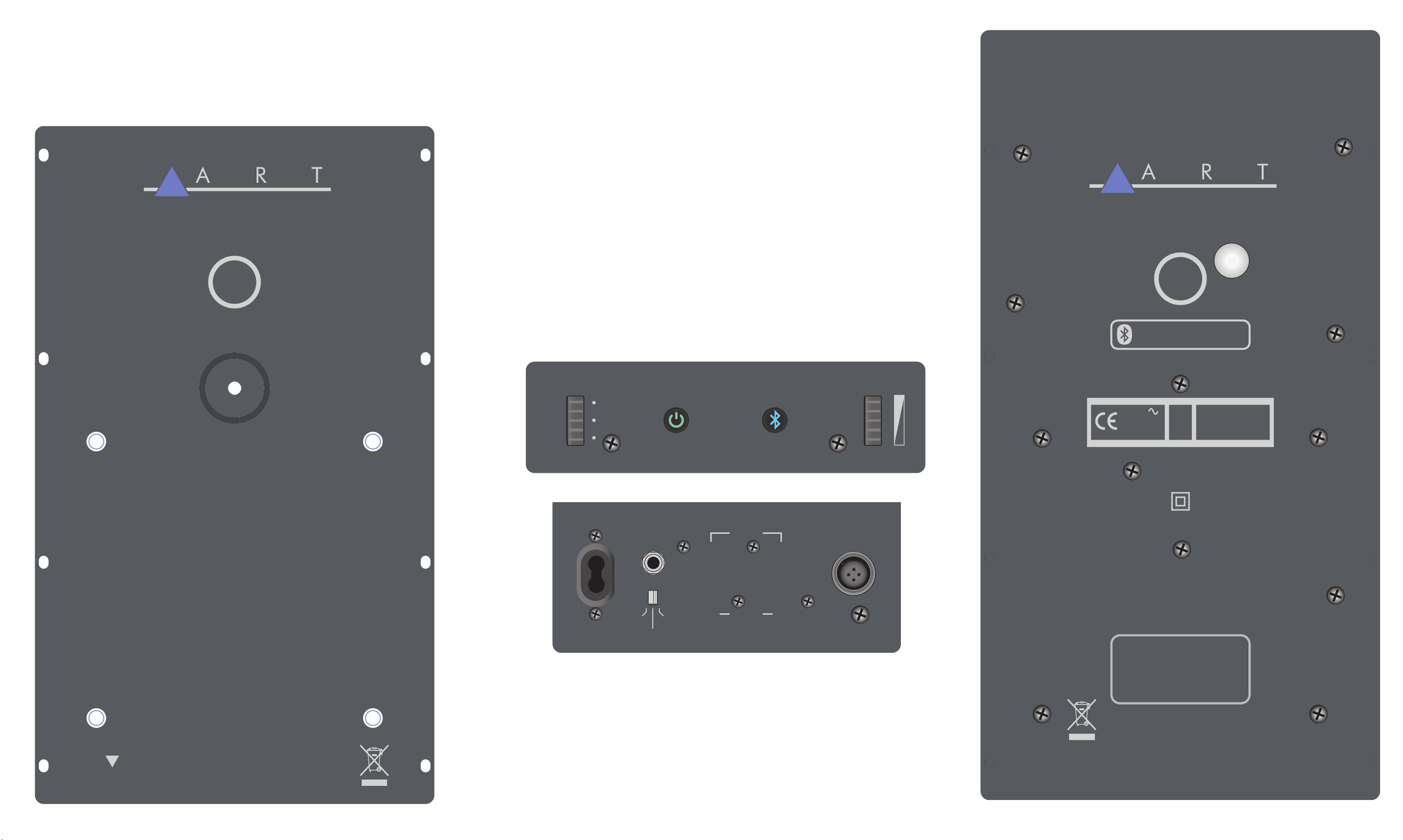
RM5
L
Theatre
Hi Fi
Ref.
AUX IN INPUTS
Stereo
TO LEFT
SPEAKER
RM5
R
Pairing: Hold four seconds
On/Off: Single Press
RM5
230V
50Hz
0,6A
DISCONNECT POWER BEFORE SERVICING!
DEBRANCHER L’APPEREIL AVANT D’ENLEVER LES COUVERCLES!
60Hz 1.2A
A-Z1396 / 2v0
120VAC
FROM RIGHT
SPEAKER
1/4
Space
1/2 Space
Full
Space
XLR /
Phone
Contains Transmitter Module FCC ID: A8TBM23SPKXYC2A
This device complies with Part 15 of the FCC Rules.
Operation is subject to the following two conditions: (1) this
device may not cause harmful interference, and (2) this
LeftRight
AC
device must accept any interference received, including
interference that may cause undesired operation.
DESIGNED & MANUFACTURED BY
YORKVILLE SOUND • TORONTO, CANADA
TO LEFT
SPEAKER
Page 4

SPECIFICATIONS
System Type Active 2-Way Stereo
Program Power (Watts) 300 W
Max SPL (dB) 109
Frequency Response (Hz +/- 3dB) 45-22,000
Crossover Frequency (Hz) 2200
HF Driver(s)
HF Program Power (Watts) 25W (x 2)
LF Program Power (Watts) 125W (x 2)
LF Protection Thermal / Peak (X-max)
Inputs
Mode Controls
Level Controls Master Level
Cabinet Material Aluminum Unibody Design
Power Supply USA – 105 to 125 VAC /60HZ
Bass Principal Dual Opposing Passive Radiator
Dimensions (H, W, D) 12.4-inch x 7.6-inch x 3.6-inch each speaker
High Resolution Ring Radiator
Center Plug to Improve Off Axis Response
refoow etisopmoC xaM-X hgiH hcni-5 )s(revirD FL
2 x XLR & ¼-inch TRS Balanced Combi-Jacks (Left/Right),
Stereo 1/8-inch TRS Jack / Bluetooth™ Wireless Streaming
Reference, HiFi, and Theatre Room Compensation
1/4 Space, 1/2 Space and Full Space
rekaeps hcae mm9 x mm91 x mm13
)riaP( gk9 / sbl02 thgieW
noitanitsed fo yrtnuoc rof derugifnoc era stinu tropxE
ART maintains a policy of constant product improvement. ART reserves the right to make changes in design,
or make additions to, or improvements upon, this product without any obligation to install same on products
previously manufactured. Therefore, specifications are subject to change without notice.
88
Page 5
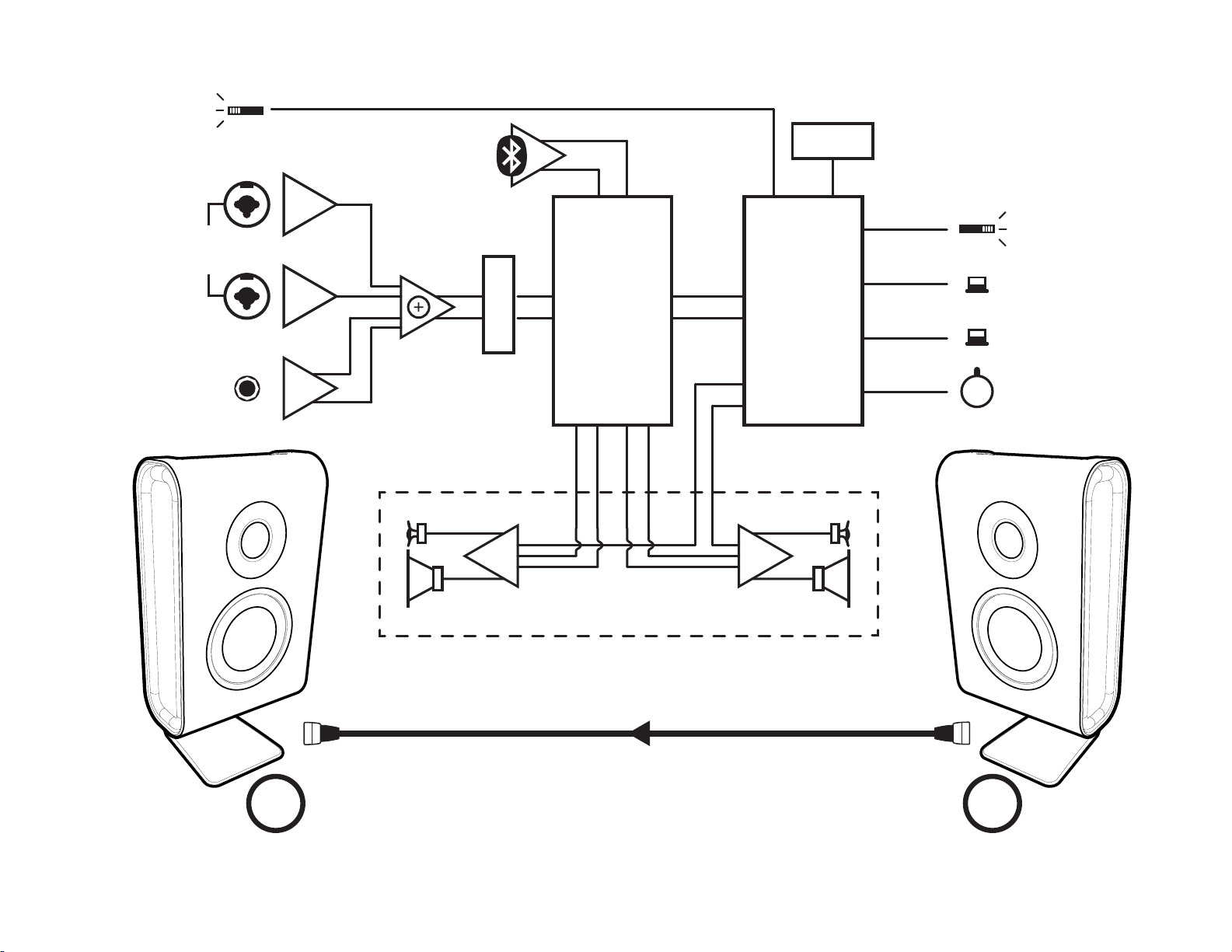
1/4 Space
1/2 Space
Full Space
Bluetooth
TM
Timer
Sleeper
INPUTS
XLR /
Phone
AUX IN
Stereo
L
Pre Amp
ADC
R
L
R
Biamp
L
DSP Control
Processor
Amp
Mute
Biamp
R
Theatre
Hi Fi
Reference
Power
Bluetooth
Level
TM
RIGHT RM5
RL
Page 6

ART RM5 PARTS Parts List 8/20/2018
YS # Description Qty. YS # Description Qty. YS # Desc ription Qty.
6451 __4N7 250V 20%CAP BLK 'Y' 10MM AC 1 8256 FERRITE BEAD 600R @100MHZ 0805 SMT 3
5635 1000U 35V 20%CAP BLK RADIAL ELECT 1 8318 ADAU1401 28/56 DSP 2AD4DA SMT IC 2
5863 6800U 25V 20%CAP BLK 16X40MM EL 4 7918 LM1117 REGULATOR 5V0 SMT SOT223 2
4453 _50K B LIN 12MM 4PIN HORZ DT P40 1 8285 BM23 BLUETOOTH DIGITAL SMT MOD 1
9102 RM5 MONITOR FOOT PAD 3 7661 LM393D DUAL COMPARATOR SMT SO-8 2
3465 WIRE TO BOARD CRIMP 16-18 AWG TIN 4 7817 33078 DUAL OPAMP SMT SO-8 4
4186 3.5MM JCK PCB MT VERT ST 1 7817 33078 DUAL OPAMP SMT SO-8 4
4194 2X2 3 MM MICRO MATE-N-LOK VRT 1 7883 26 PIN 25SQ 100 PIN SIL SMT 1
4090 1/4IN &XLR PCB MT VERT COMBO NCJ6-V 2 5998 BL/RD LED 2V1 20MA 0805 SMT 5
2370 7 CIR PH-HEADER 2MM 2 6692 11.2896MHZ CRYSTAL 4-PIN SMT 1
3121 04 20AWG 06 R-B,Y-B MATENLOK-BARREL 1 4512 _10K 25% ACP KAP TRIM POT SMT T&R 4
3118 04 18AWG 08 R-B,Y-B TWPR FSTON-156 1 7882 W250 0R 1206 SMT RES 2
3119 04 18AWG 12 R-B,Y-B TWPR FSTON-BARL 1 7998 W750 0R 1% 2010 SMT JMP 5
3115 PATCH 07 22AWG 3.0 PH 1 7868 1W00 0R047 5% 2512 SMT RES 12
3126 BARREL CONNECTOR KIT FOR RM5 1 4615 W250 4R7 5% 1206 SMT RES 1
2337 4 CIR XH-HEADER 0.098IN 2 7821 W125 10R0 1% 0805 SMT RES 14
2327 6 CIR XH-HEADER 0.098IN 2 8131 W500 10R 5% 1210 SMT RES 8
2381 09 CIR XH-HEADER RA 0.098IN 2 7923 W333 33R 5% 1210 SMT RES 10
3065 PATCH 04 22AWG 08.0 XH 1 7854 W125 47R 5% 0805 SMT RES 20
3117 PATCH 09 22AWG 13.0 XH 1 7854 W125 47R 5% 0805 SMT RES 16
3044 PATCH 06 22AWG 07.0 XH FLAT 1 7624 W100 100R 1% 0805 SMT RES 4
8554 SQUARE PROFILE O RING .5"ID 70 DURO 4 7624 W100 100R 1% 0805 SMT RES 11
2493 FUSE T3.15A 300V RAD SLOW T&R 1 7709 W100 301R 1% 0805 SMT RES 4
WEDGEKIT WEDGE SPACER KIT FOR RM SERIES 1 8213 W250 330R 5% 1206 SMT RES 16
7582 _4 OHM .75" PEERLESS RING RADIATOR 2 7856 W125 470R 5% 0805 SMT RES 4
3810 4" NYLON CABLE TIE 3 7673 W100 475R 1% 0805 SMT RES 2
4210 RECEPTACLE 2 PRONG IEC 1 7621 W100 1K0 1% 0805 SMT RES 4
RM5KIT RM5 UNIBODY/PASSIVES/STAND PAIR 1 7621 W 100 1K0 1% 0805 SMT RES 4
6535 HEADER SIL (FEMALE) 26 SOCKET 1 7859 W125 2K2 5% 0805 SMT RES 4
3538 24 PIN BREAKAWAY LOCK .156 0.167 7859 W125 2K2 5% 0805 SMT RES 2
4162 2 PIN POWER PIN HEADER MALE POLZED 1 7633 W100 2K74 1% 0805 SMT RES 4
4163 5 PIN POWER PIN HEADER MALE POLZED 1 7678 W125 3K92 1% 0805 SMT RES 4
9089 KNOB RM SERIES BUTTON IO 5 7795 W 063 4K02 1% 0603 SMT RES 8
3472 8' 18AWG IEC 320 2 PRONG LINE CORD 1 7642 W100 4K75 1% 0805 SMT RES 6
9985 4-40 NYLON INSERT LOK NUT 2 7679 W100 4K99 1% 0805 SMT RES 13
8788 1/4-20 KEPS NUT ZINC 2 8192 W125 5K76 1% 0805 SMT RES 6
4155 RELAY 1A 10AMP DC05 040MA PC-S HC 1 7680 W 100 6K98 1% 0805 SMT RES 1
9145 .100" 48X96 UTILITY ALUMINUM 0.667 7625 W100 10K0 1% 0805 SMT RES 18
9001 4-40X5/16 PAN PH MS ZN W/STAR WASHR 8 8257 W125 11K0 1% 0805 SMT RES 2
8729 #4 X 3/8 FLAT QUAD TYPE A/B TBZ 4 7628 W100 15K0 1% 0805 SMT RES 10
9975 #4 X 1/2 PAN PHILIP TYPE A/B TBZ 26 7823 W100 18K2 1% 0805 SMT RES 2
8808 4-40X3/4 FLAT PHIL MS B.O.& WA 3 7900 W 125 30K 0.5% 0805 SMT RES 8
8831 6-32X1/4 PAN PHIL TAPTITE ZINC CLEA 8 8135 W125 47K 5% 0805 SMT RES 8
8713 6-32X5/8 FL QD MS ZINC 4 5088 W125 49K9 1% 0805 SMT RES 4
8779 1/4-20X2X1/2 CARRIAGE BOLT ZINC 1 4963 W125 64K9 1% 0805 SMT RES 3
9093 #6 X 3/8 PAN PHILIP PLASTITE TBZ 2 8222 W100 1K02 1% 0603 SMT RES 7
7730 __2.2UH COIL SMT 1 8233 W100 19K6 1% 0603 SMT RES 4
2910 120.0UH COIL SR4018T 1R6 SMT 1 7866 W 125 1M 5% 0805 SMT RES 2
8143 _27P 50V 5%CAP 0805 SMT NPO 2 7834 _10K 5% THERMISTOR NTC 0603 SMT 1
7748 _47P 100V 5%CAP 0805 SMT NPO 2 7837 MMBT5401 PNP SOT-23 SMT 5
7813 _47P 50V 5%CAP 0805 SMT NPO 1 8022 MMBTA64LT1G PNP DARL SOT-23 SMT 20
7927 100P 50V 10%CAP 0805 SMT NPO 2 7806 MMBF4391LT1 NCH JFET SOT-23 SMT T&R 4
8272 220P 100V 10%CAP 0805 SMT X7R 7 7840 IRF530NS N CH MFET D2PAK SMT TS 4
7602 330P 50V 5%CAP 0805 SMT NPO 2 8002 TEST POINT MINIATURE SMT 8
7871 470P 50V 5%CAP 0603 SMT NPO 6 3752 1/4 SNAP IN SPACER RICHCO 4
7693 __1N 50V 5%CAP 0805 SMT NPO 14 2335 #4X500MIL NYLON STANDOFF NUT 3
8277 __1N8 50V 5%CAP 0805 SMT NPO 4 9079 4-40X7/16 ALU M HEX SPACER 1
7694 __3N3 25V 5%CAP 0805 SMT NPO 1 8505 4-40X1/2 ALUM HEX SPACER 1
7799 __5N6 50V 5%CAP 0805 SMT C0G 6 3858 #4X3/4 PLASTIC HEX SPACER 2
7737 _10N 50V 10%CAP 0805 SMT X7R 1 8681 4-40 X .940" ALUMINUM HEX SPACER 1
8176 _47N 100V 10%CAP 1206 SMT X7R 4 2380 10-32X3/8 BLND PEM THRD SPCR BZ 4
5979 100N 50V 5%CAP 0805 SMT X7R 4 7581 5.25" 8R 160WPGM WOOFER CUS DUSTCAP 2
7767 100N 16V 10%CAP 0603 SMT X7R 26 9044 0.500XOD1.5XID0.397 WASHER NATURAL 1
7601 220N 50V 10%CAP 1206 SMT X7R 1 8852 #6 INTERNAL TOOTH LOCKWASHER 8
7769 __1U 50V 20%CAP 4.3X3.9 SMT ELC 7 8947 1.250ODX1/4ID FENDER W ASHER ZINC CL 1
7879 __1U 50V 20%CAP 3.3MM SMT ELE 2 6548 2P3T SLID SW PCMT V 1
7886 __4U7 25V 20%CAP 4X5.5 SMT ELC 1 4200 SP3T ROTA SW PCMT H RS1201 1
7780 _10U 16V 20%CAP SMT ELC 8 3439 DPDT MINI PC VERT MOMENTARY 1
7916 _10U 25V 20%CAP 5X5.4 SMT EL 10 3522 DPDT MINI PC VERT SNP ALT 1
8140 _15U 35V 10%CAP 6032 SMT TNT 1 3958 BLK 18AW G 36STND WIRE DOU/INS 1.25
8139 _22U 25V 20%CAP 1210 SMT X7R 4 1254 1VA 16V XFMR 36X31X25MM 115/230 1
7880 _47U 35V 20%CAP 6.3MM SMT ELE 2 CH1345 XFMR:RM5 1
8141 100U 10V 20%CAP 3528 SMT TNT 2 8425 1357 2MM X .29" 150 FEET WITH ADHES 17.25
8510 220U 16V 20%CAP 8X6.5 SMT ELE 8
7893 MBRA340T3 40V 3A SHTKY 403D SMT 25
7984 BAS21L 250V 200MA SOT23 SMT 20
7700 5237B 8V2 0W2 SOT-23 SMT ZEN 2
7830 MM3Z12VT1G 12V0 0W2 5% SMT ZEN 8
7831 MM3Z15VT1G 15V0 0W2 5% SMT ZEN 6
7832 MM3Z18VT1G 18V0 0W2 5% SMT ZEN 1
Page 7

M1494 REF Parts Reference List 8/17/2018
REF YS # Description REF YS # Description REF YS # Description REF YS # Description REF YS # Description
Q4
7014 MJD127 PNP DARL DPAK3 SMT R153B 7628 W100 15K0 1% 0805 SMT RES U8B 7817 33078 DUAL OPAMP SMT SO-8
C1A
7799 __5N6 50V 5%CAP 0805 SMT C0G
C1B
7799 __5N6 50V 5%CAP 0805 SMT C0G
C2A
7799 __5N6 50V 5%CAP 0805 SMT C0G
C2B
7799 __5N6 50V 5%CAP 0805 SMT C0G
C3A
7693 __1N 50V 5%CAP 0805 SMT NPO
C3B
7693 __1N 50V 5%CAP 0805 SMT NPO
C4A
7780 _10U 16V 20%CAP SMT ELC
C4B
7780 _10U 16V 20%CAP SMT ELC
C5
7879 __1U 50V 20%CAP 3.3MM SMT ELE
C6A
7693 __1N 50V 5%CAP 0805 SMT NPO
C6B
7693 __1N 50V 5%CAP 0805 SMT NPO
C7
7879
C38A
C38B
C49A
C49B
C50A
C50B
C51A
C51B
C52A
C52B
C53A
C53B
C59A
C59B
C60A
C60B
C62A
C62B
C64A
C64B
C65A
C65B
C66A
C66B
C67A
C67B
C68A
C68B
C69A
C69B
C70A
C70B
C71A
C71B
C72A
C72B
C95A
C95B
D1
D2
D24A
D24B
D30A
D30B
D32A
D32B
D33A
D33B
D34A
D34B
D35A
D35B
D37A
D37B
D38A
D38B
D41A
D41B
D42A
D42B
P2A
P2B
P3A
P3B
Q1
Q2
Q3
__1U 50V 20%CAP 3.3MM SMT ELE
8510 220U 16V 20%CAP 8X6.5 S MT ELE
8510 220U 16V 20%CAP 8X6.5 S MT ELE
5979 100N 50V 5%CAP 0805 SMT X7R
5979 100N 50V 5%CAP 0805 SMT X7R
7693 __1N 50V 5%CAP 0805 SMT NPO
7693 __1N 50V 5%CAP 0805 SMT NPO
8510 220U 16V 20%CAP 8X6.5 S MT ELE
8510 220U 16V 20%CAP 8X6.5 S MT ELE
7693 __1N 50V 5%CAP 0805 SMT NPO
7693 __1N 50V 5%CAP 0805 SMT NPO
8143 _27P 50V 5%CAP 0805 SMT NP O
8143 _27P 50V 5%CAP 0805 SMT NP O
7799 __5N6 50V 5%CAP 0805 SMT C0G
7799 __5N6 50V 5%CAP 0805 SMT C0G
7780 _10U 16V 20%CAP SMT ELC
7780 _10U 16V 20%CAP SMT ELC
7927 100P 50V 10%CAP 0805 SMT NP O
7927 100P 50V 10%CAP 0805 SMT NP O
7780 _10U 16V 20%CAP SMT ELC
7780 _10U 16V 20%CAP SMT ELC
7693 __1N 50V 5%CAP 0805 SMT NPO
7693 __1N 50V 5%CAP 0805 SMT NPO
8510 220U 16V 20%CAP 8X6.5 S MT ELE
8510 220U 16V 20%CAP 8X6.5 S MT ELE
5979 100N 50V 5%CAP 0805 SMT X7R
5979 100N 50V 5%CAP 0805 SMT X7R
7693 __1N 50V 5%CAP 0805 SMT NPO
7693 __1N 50V 5%CAP 0805 SMT NPO
7748 _47P 100V 5%CAP 0805 SMT NP O
7748 _47P 100V 5%CAP 0805 SMT NP O
7693 __1N 50V 5%CAP 0805 SMT NPO
7693 __1N 50V 5%CAP 0805 SMT NPO
7780 _10U 16V 20%CAP SMT ELC
7780 _10U 16V 20%CAP SMT ELC
8510 220U 16V 20%CAP 8X6.5 S MT ELE
8510 220U 16V 20%CAP 8X6.5 S MT ELE
7602 330P 50V 5%CAP 0805 SMT NP O
7602 330P 50V 5%CAP 0805 SMT NP O
7830 MM3Z12VT1G 12V0 0W2 5% S MT ZEN
7830 MM3Z12VT1G 12V0 0W2 5% S MT ZEN
7984 BAS21L 250V 200MA SOT23 SMT
7984 BAS21L 250V 200MA SOT23 SMT
7750 CDSF4148 75V 0A15 1005 SMT
7750 CDSF4148 75V 0A15 1005 SMT
7984 BAS21L 250V 200MA SOT23 SMT
7984 BAS21L 250V 200MA SOT23 SMT
7984 BAS21L 250V 200MA SOT23 SMT
7984 BAS21L 250V 200MA SOT23 SMT
7984 BAS21L 250V 200MA SOT23 SMT
7984 BAS21L 250V 200MA SOT23 SMT
7848 MURA240T3 400V 2A DIO 403D SMT
7848 MURA240T3 400V 2A DIO 403D SMT
7848 MURA240T3 400V 2A DIO 403D SMT
7848 MURA240T3 400V 2A DIO 403D SMT
7750 CDSF4148 75V 0A15 1005 SMT
7750 CDSF4148 75V 0A15 1005 SMT
7984 BAS21L 250V 200MA SOT23 SMT
7984 BAS21L 250V 200MA SOT23 SMT
7984 BAS21L 250V 200MA SOT23 SMT
7984 BAS21L 250V 200MA SOT23 SMT
4512 _10K 25% ACP KAP TRIM POT SMT T&R
4512 _10K 25% ACP KAP TRIM POT SMT T&R
4512 _10K 25% ACP KAP TRIM POT SMT T&R
4512 _10K 25% ACP KAP TRIM POT SMT T&R
7015 MJD122 NPN DARL DPAK3 SMT
7838 MMBT3904 NPN SOT-23 SMT
7837 MMBT5401 PNP SOT-23 SMT
Q21A
7015 MJD122 NPN DARL DPAK3 SMT
Q21B
7015 MJD122 NPN DARL DPAK3 SMT
Q23A
8022 MMBTA64LT1G PNP DARL SOT-23 S MT
Q23B
8022 MMBTA64LT1G PNP DARL SOT-23 S MT
Q24A
7806 MMBF4391LT1 NCH JFET SOT-23 SMT T&R
Q24B
7806 MMBF4391LT1 NCH JFET SOT-23 SMT T&R
Q25A
7014 MJD127 PNP DARL DPAK3 SMT
Q25B
7014 MJD127 PNP DARL DPAK3 SMT
Q26A
7840 IRF530NS NCH MFET D2PAK SMT TS
Q26B
7840 IRF530NS NCH MFET D2PAK SMT TS
Q27A
7015 MJD122 NPN DARL DPAK3 SMT
Q27B
7015 MJD122 NPN DARL DPAK3 SMT
Q28A
7015 MJD122 NPN DARL DPAK3 SMT
Q28B
7015 MJD122 NPN DARL DPAK3 SMT
Q29A
8022 MMBTA64LT1G PNP DARL SOT-23 S MT
Q29B
8022 MMBTA64LT1G PNP DARL SOT-23 S MT
Q30A
7806 MMBF4391LT1 NCH JFET SOT-23 SMT T&R
Q30B
7806 MMBF4391LT1 NCH JFET SOT-23 SMT T&R
Q31A
7014 MJD127 PNP DARL DPAK3 SMT
Q31B
7014 MJD127 PNP DARL DPAK3 SMT
Q32A
7014 MJD127 PNP DARL DPAK3 SMT
Q32B
7014 MJD127 PNP DARL DPAK3 SMT
Q33A
7839 IRF9530NS PCH MFET D2PAK SMT TS
Q33B
7839 IRF9530NS PCH MFET D2PAK SMT TS
R1A
7854 W125 47R 5% 0805 SMT RE S
R1B
7854 W125 47R 5% 0805 SMT RE S
R2A
7854 W125 47R 5% 0805 SMT RE S
R2B
7854 W125 47R 5% 0805 SMT RE S
R3
7821 W125 10R0 1% 0805 SMT RE S
R4
7709 W100 301R 1% 0805 SMT RE S
R5
7628 W100 15K0 1% 0805 SMT R ES
R6A
7882 W250 0R 1206 SMT RES
R6B
7882 W250 0R 1206 SMT RES
R7
7821 W125 10R0 1% 0805 SMT RE S
R8
7709 W100 301R 1% 0805 SMT RE S
R9
7628 W100 15K0 1% 0805 SMT R ES
R10
7821 W125 10R0 1% 0805 SMT RE S
R11A
7821 W125 10R0 1% 0805 SMT RE S
R11B
7821 W125 10R0 1% 0805 SMT RE S
R12
7821 W125 10R0 1% 0805 SMT RE S
R13A
5084 W125 33R 5% 0805 SMT RE S
R13B
5084 W125 33R 5% 0805 SMT RE S
R45A
7854 W125 47R 5% 0805 SMT RE S
R45B
7854 W125 47R 5% 0805 SMT RE S
R46A
8213 W250 330R 5% 1206 SMT RE S
R46B
8213 W250 330R 5% 1206 SMT RE S
R47A
8213 W250 330R 5% 1206 SMT RE S
R47B
8213 W250 330R 5% 1206 SMT RE S
R48A
7854 W125 47R 5% 0805 SMT RE S
R48B
7854 W125 47R 5% 0805 SMT RE S
R64A
7633 W100 2K74 1% 0805 SMT R ES
R64B
7633 W100 2K74 1% 0805 SMT R ES
R98A
7821 W125 10R0 1% 0805 SMT RE S
R98B
7821 W125 10R0 1% 0805 SMT RE S
R99A
7923
R99B
R102A
R102B
R114A
R114B
R115A
R115B
R116A
R116B
R118A
R118B
R119A
R119B
R141A
R141B
R143A
R143B
R144A
R144B
R145A
R145B
R146A
R146B
R153A
W333 33R 5% 1210 SMT RES
7923 W333 33R 5% 1210 SMT RE S
7900 W125 30K 0.5% 0805 S MT RES
7900 W125 30K 0.5% 0805 S MT RES
7709 W100 301R 1% 0805 SMT RE S
7709 W100 301R 1% 0805 SMT RE S
7868 1W00 0R047 5% 2512 SMT RE S
7868 1W00 0R047 5% 2512 SMT RE S
7900 W125 30K 0.5% 0805 S MT RES
7900 W125 30K 0.5% 0805 S MT RES
7859 W125 2K2 5% 0805 SMT R ES
7859 W125 2K2 5% 0805 SMT R ES
8192 W125 5K76 1% 0805 SMT R ES
8192 W125 5K76 1% 0805 SMT R ES
7868 1W00 0R047 5% 2512 SMT RE S
7868 1W00 0R047 5% 2512 SMT RE S
7856 W125 470R 5% 0805 SMT RE S
7856 W125 470R 5% 0805 SMT RE S
5088 W125 49K9 1% 0805 SMT R ES
5088 W125 49K9 1% 0805 SMT R ES
7821 W125 10R0 1% 0805 SMT RE S
7821 W125 10R0 1% 0805 SMT RE S
7923 W333 33R 5% 1210 SMT RE S
7923 W333 33R 5% 1210 SMT RE S
7628 W100 15K0 1% 0805 SMT R ES
R156A
7628 W100 15K0 1% 0805 SMT RES
R156B
7628 W100 15K0 1% 0805 SMT RES
R162A
7854 W125 47R 5% 0805 SMT RES
R162B
7854 W125 47R 5% 0805 SMT RES
R166A
7621 W100 1K0 1% 0805 SMT RES
R166B
7621 W100 1K0 1% 0805 SMT RES
R190A
8213 W250 330R 5% 1206 SMT RES
R190B
8213 W250 330R 5% 1206 SMT RES
R196A
8213 W250 330R 5% 1206 SMT RES
R196B
8213 W250 330R 5% 1206 SMT RES
R197A
7854 W125 47R 5% 0805 SMT RES
R197B
7854 W125 47R 5% 0805 SMT RES
R199A
8213 W250 330R 5% 1206 SMT RES
R199B
8213 W250 330R 5% 1206 SMT RES
R200A
8213 W250 330R 5% 1206 SMT RES
R200B
8213 W250 330R 5% 1206 SMT RES
R223A
7624 W100 100R 1% 0805 SMT RES
R223B
7624 W100 100R 1% 0805 SMT RES
R224A
7633 W100 2K74 1% 0805 SMT RES
R224B
7633 W100 2K74 1% 0805 SMT RES
R225A
7854 W125 47R 5% 0805 SMT RES
R225B
7854 W125 47R 5% 0805 SMT RES
R226A
8192 W125 5K76 1% 0805 SMT RES
R226B
8192 W125 5K76 1% 0805 SMT RES
R227A
7900 W125 30K 0.5% 0805 SMT RES
R227B
7900 W125 30K 0.5% 0805 SMT RES
R228A
7821 W125 10R0 1% 0805 SMT RES
R228B
7821 W125 10R0 1% 0805 SMT RES
R229A
7923 W333 33R 5% 1210 SMT RES
R229B
7923 W333 33R 5% 1210 SMT RES
R230A
7854 W125 47R 5% 0805 SMT RES
R230B
7854 W125 47R 5% 0805 SMT RES
R231A
7859 W125 2K2 5% 0805 SMT RES
R231B
7859 W125 2K2 5% 0805 SMT RES
R232A
8192 W125 5K76 1% 0805 SMT RES
R232B
8192 W125 5K76 1% 0805 SMT RES
R233A
7868 1W00 0R047 5% 2512 SMT RES
R233B
7868 1W00 0R047 5% 2512 SMT RES
R234A
7868 1W00 0R047 5% 2512 SMT RES
R234B
7868 1W00 0R047 5% 2512 SMT RES
R235A
7900 W125 30K 0.5% 0805 SMT RES
R235B
7900 W125 30K 0.5% 0805 SMT RES
R236A
7868 1W00 0R047 5% 2512 SMT RES
R236B
7868 1W00 0R047 5% 2512 SMT RES
R237A
7868 1W00 0R047 5% 2512 SMT RES
R237B
7868 1W00 0R047 5% 2512 SMT RES
R240A
7628 W100 15K0 1% 0805 SMT RES
R240B
7628 W100 15K0 1% 0805 SMT RES
R242A
5088 W125 49K9 1% 0805 SMT RES
R242B
5088 W125 49K9 1% 0805 SMT RES
R243A
7856 W125 470R 5% 0805 SMT RES
R243B
7856 W125 470R 5% 0805 SMT RES
R244A
7821 W125 10R0 1% 0805 SMT RES
R244B
7821 W125 10R0 1% 0805 SMT RES
R245A
7923 W333 33R 5% 1210 SMT RES
R245B
7923 W333 33R 5% 1210 SMT RES
R246A
7621 W100 1K0 1% 0805 SMT RES
R246B
7621 W100 1K0 1% 0805 SMT RES
R247A
7854 W125 47R 5% 0805 SMT RES
R247B
7854 W125 47R 5% 0805 SMT RES
R248A
7628 W100 15K0 1% 0805 SMT RES
R248B
7628 W100 15K0 1% 0805 SMT RES
R249A
7854 W125 47R 5% 0805 SMT RES
R249B
7854 W125 47R 5% 0805 SMT RES
R250A
8213 W250 330R 5% 1206 SMT RES
R250B
8213 W250 330R 5% 1206 SMT RES
R251A
8213 W250 330R 5% 1206 SMT RES
R251B
8213 W250 330R 5% 1206 SMT RES
R252A
7624 W100 100R 1% 0805 SMT RES
R252B
7624 W100 100R 1% 0805 SMT RES
TP1A
8002 TEST POINT MINIATURE SMT
TP1B
8002 TEST POINT MINIATURE SMT
TP2A
8002 TEST POINT MINIATURE SMT
TP2B
8002 TEST POINT MINIATURE SMT
TP3A
8002 TEST POINT MINIATURE SMT
TP3B
8002 TEST POINT MINIATURE SMT
TP4A
8002 TEST POINT MINIATURE SMT
TP4B
8002 TEST POINT MINIATURE SMT
U8A
7817 33078 DUAL OPAMP SMT SO-8
U23A
7817 33078 DUAL OPAMP SMT S O-8
U23B
7817 33078 DUAL OPAMP SMT S O-8
W1
7883 26 PIN 25SQ 100 PIN SIL SMT
ZD1A
7830 MM3Z12VT1G 12V0 0W2 5% SMT ZEN
ZD1B
7830 MM3Z12VT1G 12V0 0W2 5% SMT ZEN
ZD2A
7830 MM3Z12VT1G 12V0 0W2 5% SMT ZEN
ZD2B
7830 MM3Z12VT1G 12V0 0W2 5% SMT ZEN
ZD3A
7831 MM3Z15VT1G 15V0 0W2 5% SMT ZEN
ZD3B
7831 MM3Z15VT1G 15V0 0W2 5% SMT ZEN
ZD4A
7830 MM3Z12VT1G 12V0 0W2 5% SMT ZEN
ZD4B
7830 MM3Z12VT1G 12V0 0W2 5% SMT ZEN
ZD5A
7831 MM3Z15VT1G 15V0 0W2 5% SMT ZEN
ZD5B
7831 MM3Z15VT1G 15V0 0W2 5% SMT ZEN
ZD6A
7831 MM3Z15VT1G 15V0 0W2 5% SMT ZEN
ZD6B
7831 MM3Z15VT1G 15V0 0W2 5% SMT ZEN
Page 8

M1705 Parts Reference List 8/17/2018
REF YS # Description REF YS # Description REF YS # Description REF YS # Description REF YS # Description
C112
7871 470P 50V 5%CAP 0603 SMT NPO
R25
8135 W125 47K 5% 0805 SMT RES
R119
7624 W100 100R 1% 0805 SMT RES
C1
7916 _10U 25V 20%CAP 5X5.4 SMT EL
C2
6451 __4N7 250V 20%CAP BLK 'Y' 10MM AC
C3
5863 6800U 25V 20%CAP BLK 16X40MM EL
C4
5863 6800U 25V 20%CAP BLK 16X40MM EL
C5
5863 6800U 25V 20%CAP BLK 16X40MM EL
C6
7767 100N 16V 10%CAP 0603 SMT X7R
C7
7819 _10U 10V 10%CAP 1206 SMT X5R
C8
7767 100N 16V 10%CAP 0603 SMT X7R
C9
7767 100N 16V 10%CAP 0603 SMT X7R
C10
7767 100N 16V 10%CAP 0603 SMT X7R
C11
7819 _10U 10V 10%CAP 1206 SMT X5R
C12
C13
C14
C15
C16
C17
C18
C19
C20
C21
C22
C23
C24
C25
C26
C27
C28
C29
C30
C31
C32
C33
C34
C35
C36
C37
C38
C39
C40
C41
C42
C43
C44
C49
C50
C51
C52
C53
C54
C55
C56
C57
C59
C60
C61
C74
C75
C76
C77
C81
C82
C83
C84
C85
C86
C87
C88
C89
C90
C91
C96
C97
C99
C100
C102
C103
C110
C111
100N 16V 10%CAP 0603 SMT X7R
7767
7767 100N 16V 10%CAP 0603 SMT X7R
7819 _10U 10V 10%CAP 1206 SMT X5R
7767 100N 16V 10%CAP 0603 SMT X7R
7694 __3N3 25V 5%CAP 0805 SMT NPO
7601 220N 50V 10%CAP 1206 SMT X7R
7819 _10U 10V 10%CAP 1206 SMT X5R
7767 100N 16V 10%CAP 0603 SMT X7R
7819 _10U 10V 10%CAP 1206 SMT X5R
7811 100U 25V 20%CAP 8X5.4 SMT ELE
7767 100N 16V 10%CAP 0603 SMT X7R
7819 _10U 10V 10%CAP 1206 SMT X5R
7767 100N 16V 10%CAP 0603 SMT X7R
8272 220P 100V 10%CAP 0805 SMT X7R
7769 __1U 50V 20%CAP 4.3X3.9 SMT ELC
7769 __1U 50V 20%CAP 4.3X3.9 SMT ELC
7769 __1U 50V 20%CAP 4.3X3.9 SMT ELC
7767 100N 16V 10%CAP 0603 SMT X7R
7767 100N 16V 10%CAP 0603 SMT X7R
7767 100N 16V 10%CAP 0603 SMT X7R
7767 100N 16V 10%CAP 0603 SMT X7R
7767 100N 16V 10%CAP 0603 SMT X7R
5979 100N 50V 5%CAP 0805 SMT X7R
7767 100N 16V 10%CAP 0603 SMT X7R
7769 __1U 50V 20%CAP 4.3X3.9 SMT ELC
7767 100N 16V 10%CAP 0603 SMT X7R
5863 6800U 25V 20%CAP BLK 16X40MM EL
7886 __4U7 25V 20%CAP 4X5.5 SMT ELC
7769 __1U 50V 20%CAP 4.3X3.9 SMT ELC
7880 _47U 35V 20%CAP 6.3MM SMT ELE
7737 _10N 50V 10%CAP 0805 SMT X7R
7880 _47U 35V 20%CAP 6.3MM SMT ELE
8140 _15U 35V 10%CAP 6032 SMT TNT
8141 100U 10V 20%CAP 3528 SMT TNT
7819 _10U 10V 10%CAP 1206 SMT X5R
7813 _47P 50V 5%CAP 0805 SMT NPO
8176 _47N 100V 10%CAP 1206 SMT X7R
8176 _47N 100V 10%CAP 1206 SMT X7R
8176 _47N 100V 10%CAP 1206 SMT X7R
8176 _47N 100V 10%CAP 1206 SMT X7R
7769 __1U 50V 20%CAP 4.3X3.9 SMT ELC
5979 100N 50V 5%CAP 0805 SMT X7R
7769 __1U 50V 20%CAP 4.3X3.9 SMT ELC
7819 _10U 10V 10%CAP 1206 SMT X5R
5979 100N 50V 5%CAP 0805 SMT X7R
8277 __1N8 50V 5%CAP 0805 SMT NPO
8272 220P 100V 10%CAP 0805 SMT X7R
8139 _22U 25V 20%CAP 1210 SMT X7R
8277 __1N8 50V 5%CAP 0805 SMT NPO
8272 220P 100V 10%CAP 0805 SMT X7R
8139 _22U 25V 20%CAP 1210 SMT X7R
8277 __1N8 50V 5%CAP 0805 SMT NPO
8272 220P 100V 10%CAP 0805 SMT X7R
8139 _22U 25V 20%CAP 1210 SMT X7R
7871 470P 50V 5%CAP 0603 SMT NPO
7871 470P 50V 5%CAP 0603 SMT NPO
5979 100N 50V 5%CAP 0805 SMT X7R
5979 100N 50V 5%CAP 0805 SMT X7R
5979 100N 50V 5%CAP 0805 SMT X7R
8277 __1N8 50V 5%CAP 0805 SMT NPO
5979 100N 50V 5%CAP 0805 SMT X7R
5979 100N 50V 5%CAP 0805 SMT X7R
7871 470P 50V 5%CAP 0603 SMT NPO
8272 220P 100V 10%CAP 0805 SMT X7R
7871 470P 50V 5%CAP 0603 SMT NPO
8272 220P 100V 10%CAP 0805 SMT X7R
7871 470P 50V 5%CAP 0603 SMT NPO
8272 220P 100V 10%CAP 0805 SMT X7R
C117
8139 _22U 25V 20%CAP 1210 SMT X7R
C134
5979 100N 50V 5%CAP 0805 SMT X7R
C145
5635 1000U 35V 20%CAP BLK RADIAL ELECT
C195
7916 _10U 25V 20%CAP 5X5.4 SMT EL
D1
7889 ES3D 200V 3A0 D214 SMT SMC
D2
7889 ES3D 200V 3A0 D214 SMT SMC
D3
7889 ES3D 200V 3A0 D214 SMT SMC
D4
7889 ES3D 200V 3A0 D214 SMT SMC
D5
7889 ES3D 200V 3A0 D214 SMT SMC
D6
7750 CDSF4148 75V 0A15 1005 SMT
D7
7889 ES3D 200V 3A0 D214 SMT SMC
D8
7889 ES3D 200V 3A0 D214 SMT SMC
D9
7889 ES3D 200V 3A0 D214 SMT SMC
D10
7750 CDSF4148 75V 0A15 1005 SMT
D11
7750 CDSF4148 75V 0A15 1005 SMT
D12
7893 MBRA340T3 40V 3A SHTKY 403D SMT
D13
7832 MM3Z18VT1G 18V0 0W2 5% SMT ZEN
D14
7750 CDSF4148 75V 0A15 1005 SMT
D15
7750 CDSF4148 75V 0A15 1005 SMT
D17
7750 CDSF4148 75V 0A15 1005 SMT
D18
7750 CDSF4148 75V 0A15 1005 SMT
D19
7750 CDSF4148 75V 0A15 1005 SMT
D20
7750 CDSF4148 75V 0A15 1005 SMT
D21
7700 5237B 8V2 0W2 SOT-23 SMT ZEN
D22
7750 CDSF4148 75V 0A15 1005 SMT
D23
7750 CDSF4148 75V 0A15 1005 SMT
D24
7700 5237B 8V2 0W2 SOT-23 SMT ZEN
D25
7750 CDSF4148 75V 0A15 1005 SMT
D26
7750 CDSF4148 75V 0A15 1005 SMT
D27
7750 CDSF4148 75V 0A15 1005 SMT
D28
7750 CDSF4148 75V 0A15 1005 SMT
D29
7750 CDSF4148 75V 0A15 1005 SMT
F1
2493 FUSE T3.15A 300V RAD SLOW T&R
J1
4090 1/4IN &XLR PCB MT VERT COMBO NCJ6-V
J2
4210 RECEPTACLE 2 PRONG IEC
J3
4090 1/4IN &XLR PCB MT VERT COMBO NCJ6-V
J4
4186 3.5MM JCK PCB MT VERT ST
K1
4155 RELAY 1A 10AMP DC05 040MA PC-S HC
L1
7730 __2.2UH COIL SMT
L2
8256 FERRITE BEAD 600R @100MHZ 0805 SMT
L3
8256 FERRITE BEAD 600R @100MHZ 0805 SMT
L4
8256 FERRITE BEAD 600R @100MHZ 0805 SMT
L5
2910 120.0UH COIL SR4018T 1R6 SMT
LD2
5997 RD/GN LED 2V1 20MA 0805 SMT
LD3
5997 RD/GN LED 2V1 20MA 0805 SMT
LD4
5998 BL/RD LED 2V1 20MA 0805 SMT
LD8
5998 BL/RD LED 2V1 20MA 0805 SMT
LED1
5997 RD/GN LED 2V1 20MA 0805 SMT
M1203
7998 W750 0R 1% 2010 SMT JMP
M1705
7998 W750 0R 1% 2010 SMT JMP
P1
4453 _50K B LIN 12MM 4PIN HORZ DT P40
Q1
7805 MMBT3906LT1 PNP SOT-23 SMT T&R
Q2
6692 11.2896MHZ CRYSTAL 4-PIN SMT
Q3
7837 MMBT5401 PNP SOT-23 SMT
Q4
7701 MMBTA14 NPN DARL SOT-23 SMT
Q6
7837 MMBT5401 PNP SOT-23 SMT
Q11
7837 MMBT5401 PNP SOT-23 SMT
R1
7673 W100 475R 1% 0805 SMT RES
R2
7673 W100 475R 1% 0805 SMT RES
R3
7621 W100 1K0 1% 0805 SMT RES
R4
8131 W500 10R 5% 1210 SMT RES
R5
7854 W125 47R 5% 0805 SMT RES
R7
7854 W125 47R 5% 0805 SMT RES
R8
7854 W125 47R 5% 0805 SMT RES
R9
7823 W100 18K2 1% 0805 SMT RES
R10
7854 W125 47R 5% 0805 SMT RES
R11
7621 W100 1K0 1% 0805 SMT RES
R12
7854 W125 47R 5% 0805 SMT RES
R13
7859 W125 2K2 5% 0805 SMT RES
R14
7795 W063 4K02 1% 0603 SMT RES
R15
7625 W100 10K0 1% 0805 SMT RES
R16
8233 W100 19K6 1% 0603 SMT RES
R17
8233 W100 19K6 1% 0603 SMT RES
R19
7998 W750 0R 1% 2010 SMT JMP
R20
7859 W125 2K2 5% 0805 SMT RES
R21
7854 W125 47R 5% 0805 SMT RES
R22
7854 W125 47R 5% 0805 SMT RES
R23
7678 W125 3K92 1% 0805 SMT RES
R24
7624 W100 100R 1% 0805 SMT RES
R26
7854 W125 47R 5% 0805 SMT RES
R27
7624 W100 100R 1% 0805 SMT RES
R28
7795 W063 4K02 1% 0603 SMT RES
R29
7866 W125 1M 5% 0805 SMT RES
R30
7625 W100 10K0 1% 0805 SMT RES
R31
7625 W100 10K0 1% 0805 SMT RES
R32
7678 W125 3K92 1% 0805 SMT RES
R33
7624 W100 100R 1% 0805 SMT RES
R34
8135 W125 47K 5% 0805 SMT RES
R35
7795 W063 4K02 1% 0603 SMT RES
R36
7678 W125 3K92 1% 0805 SMT RES
R37
7624 W100 100R 1% 0805 SMT RES
R38
8135 W125 47K 5% 0805 SMT RES
R39
7795 W063 4K02 1% 0603 SMT RES
R40
7625 W100 10K0 1% 0805 SMT RES
R41
7678 W125 3K92 1% 0805 SMT RES
R42
7624 W100 100R 1% 0805 SMT RES
R43
7823 W100 18K2 1% 0805 SMT RES
R44
8135 W125 47K 5% 0805 SMT RES
R45
8135 W125 47K 5% 0805 SMT RES
R46
8222 W100 1K02 1% 0603 SMT RES
R47
7866 W125 1M 5% 0805 SMT RES
R48
4615 W250 4R7 5% 1206 SMT RES
R49
7998 W750 0R 1% 2010 SMT JMP
R51
8222 W100 1K02 1% 0603 SMT RES
R54
7795 W063 4K02 1% 0603 SMT RES
R55
7679 W100 4K99 1% 0805 SMT RES
R60
4963 W125 64K9 1% 0805 SMT RES
R61
7795 W063 4K02 1% 0603 SMT RES
R62
7679 W100 4K99 1% 0805 SMT RES
R65
8222 W100 1K02 1% 0603 SMT RES
R67
7679 W100 4K99 1% 0805 SMT RES
R68
4963 W125 64K9 1% 0805 SMT RES
R69
8233 W100 19K6 1% 0603 SMT RES
R70
7679 W100 4K99 1% 0805 SMT RES
R71
7795 W063 4K02 1% 0603 SMT RES
R72
7679 W100 4K99 1% 0805 SMT RES
R73
8222 W100 1K02 1% 0603 SMT RES
R74
7998 W750 0R 1% 2010 SMT JMP
R75
4963 W125 64K9 1% 0805 SMT RES
R76
7625 W100 10K0 1% 0805 SMT RES
R77
7795 W063 4K02 1% 0603 SMT RES
R78
7679 W100 4K99 1% 0805 SMT RES
R79
7625 W100 10K0 1% 0805 SMT RES
R80
R81
R82
R83
R84
R85
R86
R87
R88
R89
R90
R91
R92
R93
R94
R95
R96
R97
R98
R99
R100
R101
R102
R103
R104
R105
R106
R107
R108
R110
R111
R112
R116
R117
R118
W100 19K6 1% 0603 SMT RES
8233
7679 W100 4K99 1% 0805 SMT RES
7679 W100 4K99 1% 0805 SMT RES
7679 W100 4K99 1% 0805 SMT RES
8131 W500 10R 5% 1210 SMT RES
7625 W100 10K0 1% 0805 SMT RES
7625 W100 10K0 1% 0805 SMT RES
8131 W500 10R 5% 1210 SMT RES
8131 W500 10R 5% 1210 SMT RES
7624 W100 100R 1% 0805 SMT RES
7625 W100 10K0 1% 0805 SMT RES
8131 W500 10R 5% 1210 SMT RES
7679 W100 4K99 1% 0805 SMT RES
8131 W500 10R 5% 1210 SMT RES
7642 W100 4K75 1% 0805 SMT RES
8131 W500 10R 5% 1210 SMT RES
8131 W500 10R 5% 1210 SMT RES
7834 _10K 5% THERMISTOR NTC 0603 SMT
7625 W100 10K0 1% 0805 SMT RES
8222 W100 1K02 1% 0603 SMT RES
7624 W100 100R 1% 0805 SMT RES
8257 W125 11K0 1% 0805 SMT RES
7625 W100 10K0 1% 0805 SMT RES
8257 W125 11K0 1% 0805 SMT RES
7625 W100 10K0 1% 0805 SMT RES
7642 W100 4K75 1% 0805 SMT RES
7625 W100 10K0 1% 0805 SMT RES
7642 W100 4K75 1% 0805 SMT RES
7625 W100 10K0 1% 0805 SMT RES
7854 W125 47R 5% 0805 SMT RES
7621 W100 1K0 1% 0805 SMT RES
7625 W100 10K0 1% 0805 SMT RES
7642 W100 4K75 1% 0805 SMT RES
7854 W125 47R 5% 0805 SMT RES
8135 W125 47K 5% 0805 SMT RES
R120
7624 W100 100R 1% 0805 SMT RES
R121
7625 W100 10K0 1% 0805 SMT RES
R122
7745 W125 0R 5% 0805 SMT RES
R123
7745 W125 0R 5% 0805 SMT RES
R124
7642 W100 4K75 1% 0805 SMT RES
R125
7625 W100 10K0 1% 0805 SMT RES
R126
8135 W125 47K 5% 0805 SMT RES
R127
8135 W125 47K 5% 0805 SMT RES
R128
7625 W100 10K0 1% 0805 SMT RES
R129
7642 W100 4K75 1% 0805 SMT RES
R130
7680 W100 6K98 1% 0805 SMT RES
R137
7621 W100 1K0 1% 0805 SMT RES
R150
7854 W125 47R 5% 0805 SMT RES
R151
7854 W125 47R 5% 0805 SMT RES
R154
7854 W125 47R 5% 0805 SMT RES
R155
7854 W125 47R 5% 0805 SMT RES
R164
7854 W125 47R 5% 0805 SMT RES
R169
7624 W100 100R 1% 0805 SMT RES
R213
8222 W100 1K02 1% 0603 SMT RES
R214
8222 W100 1K02 1% 0603 SMT RES
R215
7624 W100 100R 1% 0805 SMT RES
R216
7679 W100 4K99 1% 0805 SMT RES
R221
7679 W100 4K99 1% 0805 SMT RES
R222
7679 W100 4K99 1% 0805 SMT RES
R274
7854 W125 47R 5% 0805 SMT RES
S1
4200 SP3T ROTA SW PCMT H RS1201
S2
3522 DPDT MINI PC VERT SNP ALT
S3
3439 DPDT MINI PC VERT MOMENTARY
S4
6548 2P3T SLID SW PCMT V
T4
1254 1VA 16V XFMR 36X31X25MM 115/230
U1
7918 LM1117 REGULATOR 5V0 SMT SOT223
U2
8318 ADAU1401 28/56 DSP 2AD4DA SMT IC
U3
8173 MKL15Z64VLH4 48MHZ MCU SMT LQFP64
U4
7661 LM393D DUAL COMPARATOR SMT SO-8
U5
7890 LM2671 3V3 REG 0A5 SMT SO8
U6
7661 LM393D DUAL COMPARATOR SMT SO-8
U12
7817 33078 DUAL OPAMP SMT SO-8
U13
8285 BM23 BLUETOOTH DIGITAL SMT MOD
U14
7817 33078 DUAL OPAMP SMT SO-8
U16
7817 33078 DUAL OPAMP SMT SO-8
U18
7668 MC33079D QUAD OPAMP SMT SO14
W1
6535 HEADER SIL (FEMALE) 26 SOCKET
W3
2337 4 CIR XH-HEADER 0.098IN
W3_
2337 4 CIR XH-HEADER 0.098IN
W4
3465 WIRE TO BOARD CRIMP 16-18 AWG TIN
W4_
3465 WIRE TO BOARD CRIMP 16-18 AWG TIN
W6
4162 2 PIN POWER PIN HEADER MALE POLZED
W7
4163 5 PIN POWER PIN HEADER MALE POLZED
W8
2327 6 CIR XH-HEADER 0.098IN
W8_
2327 6 CIR XH-HEADER 0.098IN
W9
3465 WIRE TO BOARD CRIMP 16-18 AWG TIN
W9_
3465 WIRE TO BOARD CRIMP 16-18 AWG TIN
W10
2358 9 CIR XH-HEADER 0.098IN
W10_
2381 09 CIR XH-HEADER RA 0.098IN
W11
4018 10 CIR WAFER DIL VT 0.1
W13
3538 24 PIN BREAKAWAY LOCK .156
W14
2370 7 CIR PH-HEADER 2MM
W14_
2370 7 CIR PH-HEADER 2MM
W15
4194 2X2 3 MM MICRO MATE-N-LOK VRT
Page 9
1
1
2
2
3
3
4
4
5
5
6
6
7
7
8
8
9
9
10
10
11
11
12
12
13
13
14
14
15
15
16
16
17
17
K K
J J
I I
H H
G G
F F
E E
D D
C C
B B
A A
Product(s):
8009 1 10Sheet OfPCB#: Rev#: V02
Powered Studio Monitor
Description:
RM5
Yorkville Sound Ltd.
550 Granite Court
Pickering, ON
Canada L1W 3Y8
www.yorkville.com
EML Rev#: 01
To Sheet.SchDocModified: File:21-J -18 Tmp Rev: V031
9
9
W10 I
SPI_CLK
SPI_MISO
SS_DSP
SPI_MOSI
/RESET_DSP
BT_EN
MCLK
Standby_
WakeSig
BT_UART_RX
BT_UART_TX
BT_UART_TX_IND
BT_P0_4
Space_Sw_B
Space_Sw_A
BT_Switch
Mute_Switch
Mode_Switch_A
Mode_Switch_B
PowerLED
Level_T
Level_W
Level_B
Microco troller
PSgnd_
BT_RST_N
HotLimit_
Microcontroller
Microcontroller.SchDoc
ASSEMBLY NOTES
Assembly.SchDoc
Pa elParts
ECO.SchDoc
DESIGN HISTORY
History.SchDoc
PSgnd
+44V_
-44V_
Standby
SBv+
+22V_
-22V_
AmpMute
AmGnd
SBv-
HotLimit
PowerSupply
PowerSupply.SchDoc
12V
BT_SDATA_OUT
BT_LRCLK
BT_BCLK
BT_EN
BT_P0_4
BT_RST_N
BT_UART_TX
BT_UART_RX
BT_UART_TX_IND
BluTth
BT
Bluetooth_BM23.SchDoc
Left_LO_SENS
Right_LO_SENS
WakeSig
Space_Sw_A
Space_Sw_B
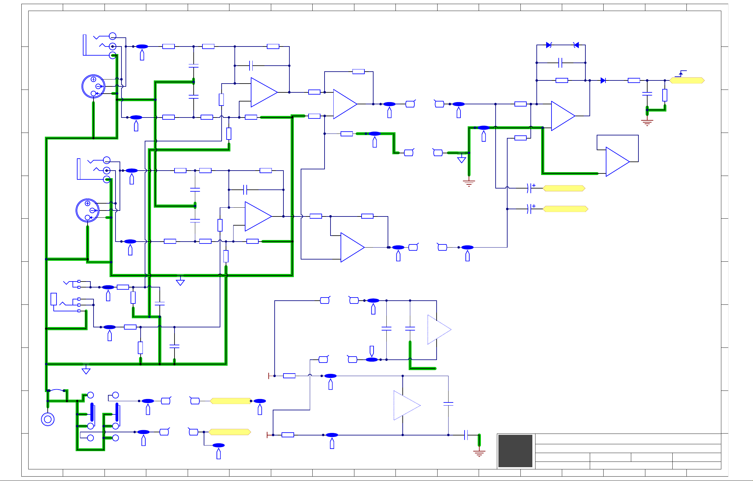
Preamp
Preamp.SchDoc
Left_LO_SENS
/RESET_DSP
SPI_MOSI
SPI_MISO
SPI_CLK
SS_DSP
MCLK
R_HI
L_HI
R_LO
L_LO
Right_LO_SENS
BT_Data
LRCLK
BCLK
DSP
DSP.SCHDOC
L_LO_SIG
R_LO_SIG
R_HI_SIG
L_HI_SIG
R_HI
L_HI
R_LO
L_LO
AmpGND
Output
Output.SchDoc
BT_EN
BT_UART_RX
BT_UART_TX
BT_RST_N
BT_UART_TX_IND
BT_P0_4
BT_EN
BT_UART_RX
BT_UART_TX
BT_RST_N
BT_UART_TX_IND
BT_P0_4
-12V
L_HI_SIG_
L_LO_SIG_
AmpGND_
R_HI_SIG_
R_LO_SIG_
-44V_
+22V_
-22V_
CDSF4148
D1005
D6
BT Ctrl
MOMENTARY
2PDT MINI
UPDOWN
3439
S3A
BT Ctrl
MOMENTARY
2PDT MINI
UPDOWN
3439
S3B
UPDOWN
3522
Po er
S2A
UPDOWN
3522
Po er
S2B
91W10A 9
1
W10 A
9
2
W10B 9
2
W10 B
9
8
W10H 9
8
W10 H
9
6
W10F 9
6
W10 F
9
5
W10E 9
5
W10 E
W100
100R
0805
R215
4200
2
4
53
S1A
Mo e
S1B
1
S1C
W100
100R
0805
R169
BLU
Bl Tth
5998
LD8A
RED
Bl Tth
5998
LD8B
93W10C 9
3
W10 C
9
4
W10D 9
4
W10 D
B
50K
4453
TB
Le el
P1A
100N
0603
16V
C32
97W10G 9
7
W10 G
9
9
W10I
Co trol PCB
BluTth
P1B
6
1
W8 A61W8A
6
2
W8 B62W8B
6
3
W8 C63W8C
6
5
W8 E65W8E
6
6
W8 F66W8F
4
3
W3 C43W3C
4
4
W3 D44W3D
4
2
W3 B42W3B
6
4
W8 D64W8D
-12V
12V
-12V
12V
1
4W13A
2
4 W13B
3
4W13C
4
4 W13D
5997
RED
Po er
LD2A
5997
GRN
Po er
LD2B
EC1
LT+LT-_
LW+
LW-_
RT+RT-_
RW+
RW-_
41W15A
4
2
W15B
4
3
W15C
4
4
W15D
W500
10R
1210
R95
W500
10R
1210
R96
100V47N
1206
C52
100V47N
1206
C55
W500
10R
1210
R84
W500
10R
1210
R4
W500
10R
1210
R88
W500
10R
1210
R87
100V47N
1206
C54
100V47N
1206
C53
W500
10R
1210
R93
W500
10R
1210
R91
26
12V A
W1A
26
-12V A
W1B
26
22V
W1C
26
RT
W1D
26
LT
W1E
26
RT
W1F
26
LT
W1G
26
-22V
W1H
26
AMPGND
W1I
26
R HI SIG
W1J
26
L HI SIG
W1K
26
R LO SIG
W1L
26
L LO SIG
W1M
26
AMPMUTE
W1N
26
22V
W1O
26
44V
W1P
26
44V
W1Q
26
RW
W1R
26
LW
W1S
26
RW
W1T
26
LW
W1U
26
RW
W1V
26
LW
W1W
26
-44V
W1
26
-44V
W1Y
26
-22V
W1Z
AmpMute
W100
10K0
0805
R40
HiFi_
Theater_
HiFi
Theater
CDSF4148
D1005
D29
+12V_A
W100
100R
0805
R119
5997
GRN
Po er
LD3B
W100
100R
0805
R120
BLU
Bl Tth
5998
LD4A
RED
Bl Tth
5998
LD4B
5997
RED
Po er
LD3A
CON HOLE 125
1
HC1
CHASSIS
LW-
LT-
RW-
RT-
N6
N8
N10
N12
N15 N16
N13
N11
N9
N7
N21 N22
N28
N32
N29
N33
N26
N30
N34
N36
N38
N27
N37
N31
N35
N18
N20
N23
N24
N25
N39
N41
N43
N45
N47
N49
N51 N52
N50
N48
N46
N44
N42
N40
N53
N56
N55
N54
N19
N14
N17
D1005
CDSF4148
D23
D1005
CDSF4148
D26
+44V_
CON HOLE 125
0
HC3
-12V_A
PsGND
N5
N57
HotLimit_
HotLimit
M te
LimitForHiTem
Sta by
W750
0R
2010
M1203
W750
0R
2010
M1705
4
1
W3 A41W3A
35V47U
6 6mm
C41
35V47U
6 6mm
C43
C41 and C43 are
placed to prevent
S1 and P1 from
tilting.
COHC1
PIN501
CON5
PIR4001 PIR4002
PIN601
PIW805
CON6
PIN801
PIW802
CON8
PIN1001
PIW804
CON10
PIN1201
PIW806
CON12
PIN1501
PIW803
CON15
PIN2101
PIW801
CON21
COR40
PIW302
PIN2501
PIW301
CON25
PIN2801
PIW303
CON28
PIN3201
PIW304
CON32
CON47
CON49
CON51
PIN5601
CON56
COW8E
COW80E
COW8B
COW80B
COW8D
COW80D
COW8F
COW80F
COW8C
COW80C
COW8A
COW80A
COW3B
COW3A
COW3C
COW3D
PIN3901
PIW1002
COW10B
CON39
PIN4101
PIW1003
CON41
CON43
CON45
PIN4701
PIN4901
PIN5101
PIN5301
CON53
PIW1009
COW10C
PIN4301
PIW1001
COW10A
PIN4501
PIW1004
COW10D
PIW1008
COW10H
PIW1005
COW10E
PIW1007
COW10G
PIW1006
COW10F
COW10I
COW30B
COW30A
COW30C
COW30D
COW100I
COW100H
COW100G
COW100F
PIHC101
PIW8005
PIW8002
PIW8004
PIW8006
PIW8003
COW1N
PIW8001
PIW3002
PIW3001
PIW3003
PIW3004
COW100B
COW100C
COW100A
COW100D
COW100E
PIR1801 PIR1802
COR18
PIN701
CON7
PIN901
CON9
PIN1101
CON11
PIN1301
CON13
PIN1601
CON16
PIN2201
CON22
PIN2601
CON26
PIN2901
CON29
PIN3301
CON33
PIW10002
PIW10003
PIW10001
PIW10004
PIW10008
PIW10005
PIW10007
PIN5401
PIW10006
CON54
PIN5501
PILD801 PILD802
PIW10009
COEC1
PIW1011
PIW1013
PIW109
PIW1010
PIW1012
PIN1901
PIW1014
CON19
PIN4001
CON40
PIN4201
CON42
PIN4401
CON44
PIN4601
CON46
PIN4801
CON48
PIN5001
CON50
PIN5201
CON52
CON55
COLD8A
COW1K
COW1M
COW1I
COW1J
COW1L
CON57
PIN5701
COW1P
COW1Q
COW1X
COW1Y
COW1C
COW1O
COW1H
COW1Z
PIP101
PIP104
PIP102
COP1A
PIP103
COLD4A
PILD401 PILD402
PIN3001
PIW1016
CON30
PIN3401
CON34
PIN3601
CON36
PIN3801
CON38
COS2B
PILD204
PILD203
COC32
PIS206
COLD2B
PIW1017
PIW1024
PIW1025
PIW103
PIW1015
PIW108
PIW1026
PIC3201
PIC3202
PIR21502
COR215
PIR21501
COR169
PIR16901PIR16902
CO=XBrd1
PIM170501
PIM170502
CO=XBrd2
PIM120301
PIM120302
PIS204PIS205
PIR12001PIR12002
PILD304
PILD303
PIR11902
PIR11901
COP1B
PIP105
PILD201
COLD2A
PILD202
COR120
COD6
PID601PID602
PIR5201
PIR5202
PIR5301
COR52
PIR5601
PIR5602
COR53
PIR601
PIR602
COR56
COR6
PIR5701
PIR5702
COR57
PIR5801
PIR5802
COR58
PIC5402
PIR5901
PIR5902
COR59
PIR6301
PIR6302
COR63
PIS104
PIS103
PIS102
PILD301
COLD3A
PILD302
COLD3B
COR119
PIS301
PIS302
PIS303
COS3A
COD23
PID2301PID2302
PIR5302
COC52
PIC5201PIC5202
COC53
PIC5301PIC5302
COC54
COC55
PIC5501PIC5502
COS1A
PIS105
PIS201
PIS202
PIS203
COS2A
COS3B
PIN1801
CON18
PIN2001
CON20
PIN2301
CON23
CON24
PIN2401
COR4
PIR401 PIR402
COR87
PIR8701 PIR8702
PIR9101
PIC5401
COR95
PIR9501 PIR9502
PIS106
PIS101
PIS304
PIS305
PIS306
COD29
PID2901
PID2902
PIW1501
COW15A
PIW1304
COW13D
PIW1302
PIW1503
COW15C
COR84
PIR8401 PIR8402
COR88
PIR8801 PIR8802
COR91
PIR9102
COR93
PIR9301 PIR9302
COR96
PIR9601 PIR9602
COS1B
COS1C
COHC3
PIHC300
COD26
PID2601PID2602
COW13B
PILD804
COLD8B
PILD803
COW13C
COW13A
COW15D
COW15B
PIN1401
PIW101
CON14
PIN1701
PIW102
CON17
PIW1303
PIN3101
CON31
PIW1301
PIN3501
CON35
PIW1504
PIN3701
CON37
PIW1502
PILD404
COLD4B
PILD403
COC41
PIC4101PIC4102
COC43
PIC4301PIC4302
PIN2701
PIW104
CON27
PIW106
PIW1018
PIW1020
PIW1022
PIW105
PIW107
PIW1019
PIW1021
PIW1023
COW1A
COW1B
COW1D
COW1F
COW1R
COW1T
COW1V
COW1E
COW1G
COW1S
COW1U
COW1W
Page 10
1
1
2
2
3
3
4
4
5
5
6
6
7
7
8
8
9
9
10
10
11
11
12
12
13
13
14
14
15
15
16
16
17
17
K K
J J
I I
H H
G G
F F
E E
D D
C C
B B
A A
Preamp
Section:
Product(s):
Pream .SchDoc
8009 2 10
Sheet OfPCB#: Rev#:
Modified:
V02
File:
21-J -18
RM5
EML Rev#: 01
Tmp Rev:
V031
Le t LO SENS
3
SH
2
1
1 4
NCJ6FAV-0
LR-PHONE
BAL LINE IN-L
4090
J1A
T
R
S
S
T
R
NCJ6FAV-0
LR-PHONE
BAL LINE IN-L
4090
J1B
1K02
W100
0603
R65
1K02
W100
0603
R73
W100
10K0
0805
R86
0603
50V470P
C86
SO14
MC33079D
7668
3
2
1
-
U18A
4186
Stereo I
3.5mm JCK
3
1
4
T
S
R
2
5
J4
12V
-12V
100N
0805
50V
C88
100N
0805
50V
C57
100N
0805
50V
C89
100N
0805
50V
C90
W125
47R
0805
R150
W125
47R
0805
R151
+15V_2
-15V_2
IGND
W100
10K0
0805
R125
0603
50V470P
C87
Ri ht LO SENS
3
SH
2
1
1 4
NCJ6FAV-0
LR-PHONE
BAL LINE IN-R
J3A
4090
T
R
S
S
T
R
NCJ6FAV-0
LR-PHONE
BAL LINE IN-R
J3B
4090
1K02
W100
0603
R213
1K02
W100
0603
R214
SO14
MC33079D
7668
5
6
7
-
U18B
IGND
W100
100R
0805
R89
W100
100R
0805
R100
SO14
MC33079D
7668
12
13
14
-
U18D
SO14
MC33079D
7668
10
9
8
-
U18C
W100
4K99
0805
R55
W100
4K99
0805
R72
W100
4K99
0805
R78
0603
50V470P
C110
0603
50V470P
C112
0603
50V470P
C99
0603
50V470P
C102
220P
0805
100V
C100
220P
0805
100V
C111
3
2
1
-
SO8
MC33078
7817
U16A
5
6
7
-
SO8
MC33078
7817
U16B
W063
4K02
0603
R54
W063
4K02
0603
R61
W063
4K02
0603
R71
W063
4K02
0603
R77
W100
4K99
0805
R83
W100
4K99
0805
R82
W100
4K99
0805
R216
W100
4K99
0805
R92
Cli 5Vrms
W100
4K99
0805
R70
W125
64K9
0805
R68
220P
0805
100V
C103
W100
4K99
0805
R81
AGND
4
8
SO8
MC33078
7817
U16C
SO14
MC33079D
7668
V
4
V-
11
U18E
7
1
W14A
7
1
W14 A
7
4
W14D
7
4
W14 D
7
2
W14B
7
2
W14 B
7
5
W14E
75W14 E
7
7
W14G 7
7
W14 G
7
3
W14C
7
3
W14 C
7
6
W14F 7
6
W14 F
W100
4K99
0805
R221
W100
4K99
0805
R222
1 4 - 1 2 - F ll
COM
MR
L
2P3T SLID
6548
S4A
1 4 - 1 2 - F ll
COM
MR
L
2P3T SLID
6548
S4B
S4C
S ace S A
S ace S B
D1005
CDSF4148
D15
Wa eSi
100N
0805
50V
C34
W125
1M
0805
R47
IGND2
IGND3
IGND
AGND
CON HOLE 125
1
HC2
W100
10K0
0805
R102
FullSpace_
1/4Space_
W100
4K99
0805
R67
1K02
W100
0603
R51
1K02
W100
0603
R99
SOT-23
8V2
D21
SOT-23
8V2
D24
GND DSP
50V1U
4 4 mm
C56
50V1U
4 4 mm
C59
TST11
TST8
TST14
TST15
TST18
TST20
TST9 TST10
TST13
TST12
TST17TST16
TST23
TST25
TST24
TST27
TST26
TST22
TST19
TST21
W125
11K0
0805
R101
W125
11K0
0805
R103
Wa e
COJ1B
COJ1A
COJ3B
COJ3A
COJ4
COS4C
PIS409
PIHC201
COHC2
PIS4010PIS4011 PIS4012
PIJ403
PIJ402
PIJ405
PIJ404
PIJ401
PIR11301 PIR11302
COR113
PIJ10R
PIJ10T
PIJ10T2
PIJ10S
PIJ10X2
PIJ10X3
PIJ10X1
PIJ10SH
PIJ30R
PIJ30T
PIJ30T2
PIJ30S
PIJ30X2
PIJ30X3
PIJ30X1
PIJ30SH
PIR8901 PIR8902
PITST1801
COTST18
PITST2001
COTST20
PIS401
PIS402
PIS403
PIS404
COS4A
PIS405
PIS406
PIS407
PIS408
COS4B
PITST801
COTST8
PITST1101
COTST11
PITST1401
COTST14
PITST1501
COTST15
COR89
PIR12502
COR125
PIR12501
COR100
PIR10001 PIR10002
PITST2501
PIR5401 PIR5402
PIR6101 PIR6102
PIR7701 PIR7702
PIC8701
PIC8702
PIR8602
COR86
PIW1407
COTST23
PIW1406
PIR8601
PITST2301
COTST25
COR54
COR213
PIR21301 PIR21302
PIC9901
COC99
PIC9902
PIC10201
COR61
PIR7101
COR71
COC102
PIC10202
COR214
PIR21401 PIR21402
COR65
PIR6501
PIR7102
PIC11001
COC110
PIC11002
PIC11201
COR77
PIR5001 PIR5002
COR50
COC87
PIC8601
COC86
COC112
PIC11202
COR73
PIR7301
PIC8602
COW140G
COW140F
PIW14007
PIW14006
COW14F
COW14G
PIC10002
PIU1806
PIR5102
COR51
PIU1805
PIR5101
PIR6502
PIR9902
PIR9901
PIR7302
COR221
PIR22101 PIR22102
PIR10102
COR101
PIR10101
COC111
PIC11102
PIU1802
COR99
PIU1803
PIR22201
PIR10302
COR103
PIR10301
POSPACE0SW0A
POSPACE0SW0B
PITST2701
COTST27
COC100
PIC10001
COR72
PIR7201 PIR7202
PIC11101
COU18A
COR222
PIR22202
PITST2401
COTST24
COR55
PIR5501
PIU1807
COU18B
PIU1801
PIR15101 PIR15102
PIR5502
PIR8201 PIR8202
PIR9201
COR150
PIR15001 PIR15002
COR151
COR82
COR78
COR92
PIW14005
PIW14004
PIU1809
PIR7801PIR7802
PIU18010
PIR9202
PIU18013
PIU18012
COW140E
COW140D
PITST2201
COTST22
PITST2601
COTST26
COR83
PIR8301 PIR8302
COR67
PIR6701PIR6702
COW14E
COW14D
PIU1808
COU18C
COR216
PIR21601 PIR21602
PIW1405
PIW1404
PITST901
PIW1401
PITST1301
PIU18014
COU18D
PITST1901
COTST9
COTST13
PIW1402
PITST1601
COTST16
COTST19
PIC5701
COTST21
COC57
PIC5702
PITST2101
COW140A
COW14A
COW140B
COW14B
PIW1403
COW140C
COW14C
PIC8801
COC88
PIC8802
COU16C
PIU1608
PIU1604
PITST1001
PIW14001
COTST10
PIR11501
PIW14002
PIR11502
COR115
PITST1701
PIW14003
COTST17
PIU1804
COU18E
PIU18011
PIC8901
COC89
PIC8902
PIC9001
COC90
PIC9002
PITST1201
COTST12
COR70
PIR7001 PIR7002
COR81
PIR8101 PIR8102
PIC5602
PIC5902
COC56
PIC5601
COC59
PIC5901
COD21
PID2101PID2102
PIR6801 PIR6802
PIU1606
PIU1605
COC103
PIC10301PIC10302
COR68
COU16B
COD24
PID2401
PID2402
PIU1607
COD15
PID1501PID1502
PIU1602
PIU1603
COR102
PIR10201 PIR10202
COU16A
PIU1601
POWAKESIG
PIR4702
PIC3401
PIC3402
COC34
PIR4701
COR47
POLEFT0LO0SENS
PORIGHT0LO0SENS
Page 11

1
1
2
2
3
3
4
4
5
5
6
6
7
7
8
8
9
9
10
10
11
11
12
12
13
13
14
14
15
15
16
16
17
17
K K
J J
I I
H H
G G
F F
E E
D D
C C
B B
A A
Bluetooth
Section:
Product(s):
Bl etooth BM23.SchDoc
8009 3 10
Sheet OfPCB#: Rev#:
Modified:
V02
File:21-J -18
RM5
EML Rev#:
01
Tmp Rev: V031
BT EN
BT SDATA OUT
BT UART T
BT UART R
W125
47R
0805
R164
100N
0805
50V
C134
10U
ELE 5mm
25V
C195
W125
47R
0805
R274
BT LRCLK
W125
47R
0805
R110
BT BCLK
BT UART T IND
DR0
5
DT0
6
P0 4
7
EAN
8
MIC1 P
9
MIC1 N
10
MIC BIAS
11
VDDA
12
AIR
13
AIL
14
BAT IN
23
P1 5
20
VDDIO
19
BK OUT
26
MFB
27
LED1
28
LED2
29
P2 4
30
P0 2
31
P0 1
21
RST N
16
ADAP IN
22
NC24SYS PWR
25
NC
18
NC
17
SLK0
4
TFS0
3
P0 3
32
HCI T D
33
P0 0
1
GND
15
P2 0
37
RFS0
2
HCI R D
34
GND
40
P2 0
39
P3 0
38
P0 5
35
P2 7
36
13.5 26mm SMT Mo le
BM23
8285
U13
1206
10V10U
C60
W125
DNS
0805
R114
BT RST N
AGND
AGND
AGND
AGND
BT_RST_N
BT_EN
W125
47R
0805
R117
4K75
W100
0805
R116
BT P0 4
1
2
3
4
5
6
W2
BT P m
AGND
5997
RED
BT St
LED1A
100N
0805
50V
C61
BT_EN
+5V_PROG
Bl Tth
W100
10K0
0805
R121
MMBT5401
7837
SOT-23
Q6
5997
GRN
BT St
LED1B
5VBT
IN
REF
OUT
SOT-223
LM1117-5
7918
U1
AGND
12V
ELE 5mm
10U 25V
C1
5VBT
TST35
TST37
TST36
TST39
TST38
D1005
CDSF4148
D27
POBT0UART0TX0IND
PIU1301
COR110
POBT0LRCLK
POBT0BCLK
POBT0SDATA0OUT
POBT0P004
PIR11001
COR114
PIR11401 PIR11402
PIR27401 PIR27402
PIC6001
PIC6002
PIR11002
COR274
COC60
PIU1302
PIU1303
PIU1304
PIU1305
PIU1306
PIU1307
PIU1308
PIU1309
PIU13010
PIU13011
PIU13012
PIU13013
PIU13014
PIU13015
COU13
PIU13040
PIU13039
PIU13038
PIU13037
PIU13036
PIU13035
PIU13034
PIU13033
PIU13032
PIU13031
PIU13030
PIU13029
PIU13028
PIU13027
PIU13026
COR116
PIR11601 PIR11602
COR164
PIR16401 PIR16402
PITST3801
COTST38
PITST3701
COTST37
POBT0EN
PITST3501
COTST35
POBT0UART0RX
POBT0UART0TX
COR117
PIR11701 PIR11702
PILED103
COLED1B
PILED104
COTST36
PITST3601
PILED102
PILED101
COLED1A
PIU102
COU1
PIU103
PIU101
COD27
PID2701PID2702
PIC101
COC1
PIC102
COW2
PIW201
PIW202
PIW203
PIW204
PIW205
PIW206
POBT0RST0N
PIU13016
PIU13017 PIU13018 PIU13019
PIU13020 PIU13021 PIU13022 PIU13023 PIU13024 PIU13025
COC195
PIC19501PIC19502
COC134
PIC13401PIC13402
PITST3901
COTST39
COQ6
PIC6101
COC61
PIC6102
POBLUTTH
PIQ602
PIQ603
PIQ601
COR121
PIR12101 PIR12102
Page 12

1
1
2
2
3
3
4
4
5
5
6
6
7
7
8
8
9
9
10
10
11
11
12
12
13
13
14
14
15
15
16
16
17
17
K K
J J
I I
H H
G G
F F
E E
D D
C C
B B
A A
ADC/DSP
Section:
Product(s):
DSP.SCHDOC
8009 4 10
Sheet OfPCB#: Rev#:
Modified:
V02
File:
21-J -18
RM5
EML Rev#:
01
Tmp Rev:
V031
3N3
0805
25V
C16
MMBT3906LT1
7805
SOT23
Q1
+1V8 SUPPLY
ADAU1701
8318
LQFP-48
RESETB
5
SELFBOOT
6
ADDR0
7
CLATCH/WP21SDA/COUT
22
MP011MP4
8
MP926MP328MP827MP615MP714MP11
19
PVDD
34
DVDD
13
VDRIVE
17
DGND
12
IOVDD
18
AVDD
36
AGND
42
AGND
37
MODE139MODE0
38
PLL_LF
35
MCLKI
32
RSVD
30
ADC_RES
3
ADC1
2
ADC0
4
VOUT3
43
VOUT1
45
FILTD
41
ADDR1 CDATA WB
20
FILTA
47
SCL/CCLK
23
MP1
10
MP5
9
MP2
29
MP10
16
VOUT0
46
VOUT2
44
CM
40
DVDD
24
AGND
1
DGND
25
AVDD
48
PGND
33
OSCO
31
1.8V Re
Reset
Mo e
Select
8-Bit
A
ADC
PLL
28 56-BIT, 50 MH
AUDIO PROCESSOR CORE
40 ms DELAY MEMORY
CLK
OSC
8-CH
Di ital
I t
8-CH
Di ital
O t t
I t O t t Matri
GPIO
Co trol
I ter ace
a
Sel boot
U2
3V3 DSP
3V3 DSP
AGND
AGND
AGND
AGND
AGND
1K0
W100
0805
R3
W100
475R0
0805
R2
1206
10V10U
C7
1206
10V10U
C20
1206
10V10U
C11
1206
10V10U
C14
Ri ht LO SENS
1206
10V10U
C23
W100
18K2
0805
R9
AGND
RESET DSP
MCLK
LRCLK
BCLK
SPI MOSI
SPI MISO
SPI CLK
SS DSP
100N
0603
16V
C13
100N
0603
16V
C12
100N
0603
16V
C24
100N
0603
16V
C19
100N
0603
16V
C10
100N
0603
16V
C9
100N
0603
16V
C8
100N
0603
16V
C6
100N
0603
16V
C15
10
1
W11A
10
2
W11B
10
3
W11C
10
4
W11D
10
5
W11E
10
6
W11F
10
7
W11G
10
8
W11H
10
9
W11I
10
10
W11J
USBi headerAGND
3V3
W125
47R
0805
R12
F0805
600R
L2
OSCILLATOR
11.2896
6692
OUT
3
E D
1
GND
2
V
4
Q2
AGND
220N
1206
50V
C17
3V3
F0805
600R
L3
1206
10V10U
C18
AGND
R HI
L HI
R LO
L LO
Le t LO SENS
BT Data
0R0
W125
0805
0R0
W125
0805
W125
47R
0805
R8
W125
47R
0805
R10
W125
47R
0805
R5
W125
47R
0805
R7
/RESET_DSP
SPI_MISO
SPI_CLK
GND DSP
INPUT_BCLK
INPUT_LRCLK
W125
64K9
0805
R60
W125
64K9
0805
R75
PIC1301
COC13
PIC1302
PIC1201
COC12
PIC1202
POLEFT0LO0SENS
PORIGHT0LO0SENS
PIC1401
COC14
PIC1402
COR60
PIR6001 PIR6002
COR75
PIR7501 PIR7502
PIQ103
PIQ102
PIR302
PIR902
COR9
PIR901
PIR10901 PIR10902
COR109
PIQ101
COR3
PIC2301
PIC2302
PO0RESET0DSP
COQ1
PIR301
COC23
PIC2401
COC24
PIC2402
PIU202
PIU204
PIU203
PIU2047
PIU2030
POSPI0MOSI
POSS0DSP
POSPI0MISO
POSPI0CLK
PIW1106
PIW1107
PIW1108
PIW1109
PIW11010
COW11F
COW11G
COW11H
COW11I
COW11J
PIC801
COC8
PIC802
PIU2013
PIU2017 PIU2018
PIU205
PIU206 PIU207
COW11A
COW11B
COW11C
COW11D
COW11E
PIU2012
PIU2024 PIU2025
PIU2021 PIU2022
PIW1101
PIW1102
PIW1103
PIW1104
PIW1105
PIU2023
PIR1201
COR12
PIR1202
PIC901
COC9
PIC902
PIU2048
PIU2010 PIU2011
PIU201
PIU208
PIU209
PIR801
COR8
PIR802
PIC1001
COC10
PIC1002
PIU2042
PIR1001
PIR1002
PIU2026
PIU2029
COR123
PIR12301
COR10
COL2
PIL201PIL202
PIC1101
COC11
PIC1102
COU2
PIU2031
PIU2033PIU2034
PIU2035PIU2036 PIU2037 PIU2038PIU2039
PIU2027PIU2028
COR122
PIR12201 PIR12202
PIR12302
PIU2032
PIU2040
PIU2014PIU2015
PIU2016
PIU2019PIU2020
POBT0DATA
POBCLK
POLRCLK
PIU2041
PIU2046
PIU2045
PIU2044
PIU2043
PIC601
PIC602
PIC701
COC6
COC7
PIC702
COR5
PIR501
PIR502
POR0HI
POL0HI
POR0LO
POL0LO
PIQ203
PIQ201
PIR202
COR2
PIR201
PIC1501
COC15
PIC1502
COQ2
COR7
PIR701
PIR702
PIC1801
PIC1802
PIC1601
COC16
PIC1602
POMCLK
PIC1901
COC18
PIQ204
COC19
PIC1902
COL3
PIC1701
COC17
PIC1702
PIQ202
PIC2001
COC20
PIC2002
PIL301PIL302
Page 13
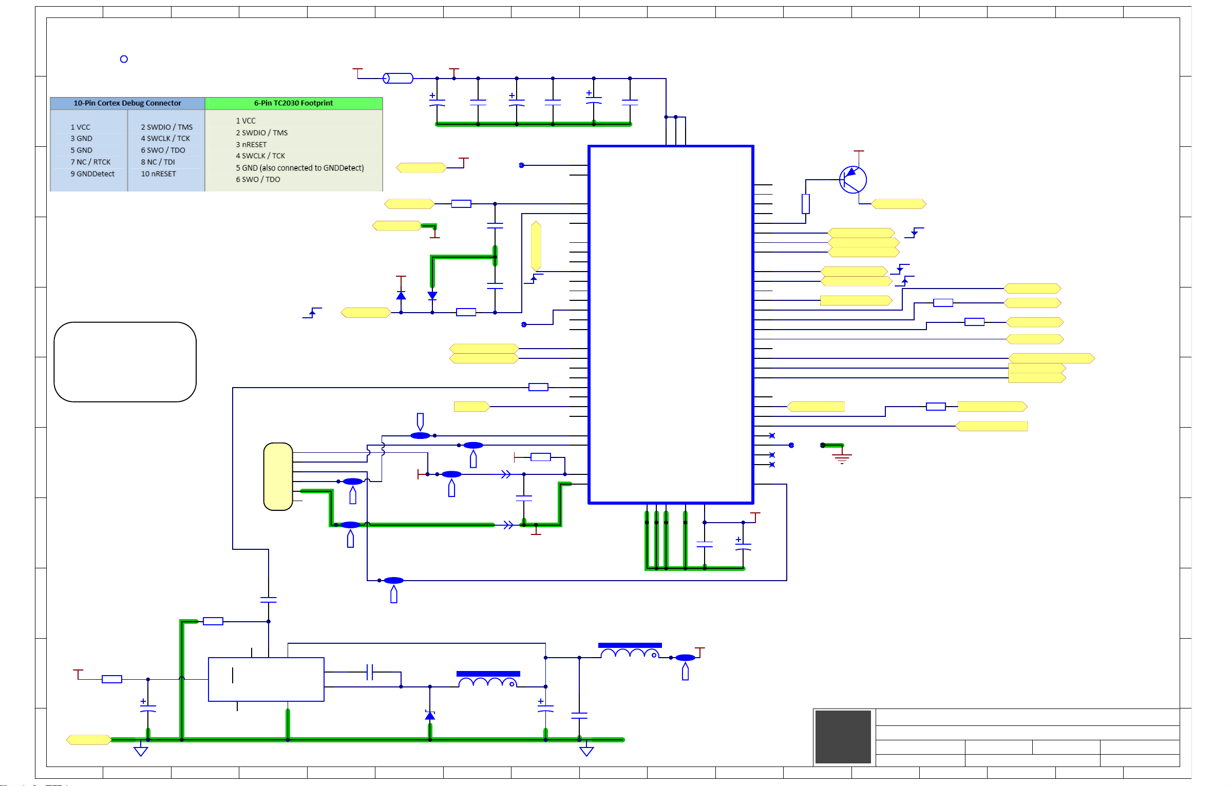
1
1
2
2
3
3
4
4
5
5
6
6
7
7
8
8
9
9
10
10
11
11
12
12
13
13
14
14
15
15
16
16
17
17
K K
J J
I I
H H
G G
F F
E E
D D
C C
B B
A A
Microcontroller
Section:
Product(s):
Microco troller.SchDoc
8009 5 10
Sheet OfPCB#: Rev#:
Modified:
V02
File:
21-J -18
RM5
EML Rev#: 01
Tmp Rev:
V031
LQFP64
MKL15Z64VLH4
8173
VDD
48
SWD DIO PTA3
25
PTB2
37
PTC5
50
PTC7
52
PTD6
63
PTE1
2
VREFH
14
PTA5
27
PTB16
39
PTC1
44
VSS
31
PTB1
36
PTB0
35
RESET b
34
PTA19
33
PTE31
19
PTE30
18
PTE24
20
PTA2
24
PTE23
12
PTE20
9
PTE17
6
VDD
3
PTE25
21
VDD
30
PTA13
29
VREFL
15
PTE21
10
PTE18
7
VSS
4
PTE29
17
VSSA
16
PTC0
43
PTA18
32
SWD CLK PTA0
22
PTA1
23
PTC9
54
PTD7
64
PTC8
53
PTD1
58
PTD0
57
PTC11
56
PTC10
55
PTD3
60
PTD2
59
PTA12
28
PTC3
46
VSS
47
PTB17
40
PTB19
42
PTB18
41
PTE22
11
PTE19
8
PTE16
5
PTD4
61
PTC4
49
PTC6
51
PTD5
62
PTE0
1
VDDA
13
PTA4
26
PTB3
38
PTC2
45
U3
3V3 C
3V3 C
1
2
100N
0603
16V
C30
100N
0603
16V
C31
1U
4.3 3 .9
50V
C28
1U
4.3 3 .9
50V
C26
1U
4.3 3 .9
50V
C36
SPI CLK
SPI MISO
SS DSP
SPI MOSI
VREFH
RESET DSP
BT UART R
BT UART T
VREFL
VREFH
3V3 C
MASTER
MCLK
VCC
1
DIO
2
RST
3
CLK
4
GND
5
SWO
6
W5
Micro_Pgm
100N
0603
16V
C29
1U
4.3 3 .9
50V
C27
100N
0603
16V
C33
W100
100R
0805
R27
100N
0603
16V
C35
100N
0603
16V
C37
Connect N1 & N2 for I2C when using USBi
3V3
W125
47R
0805
R26
W125
47R
0805
R21
W125
47R
0805
R22
F0805
600R
L4
MMBT5401
7837
SOT-23
Q11
1K0
W100
0805
R137
AGND
AGND
AGND
AGND
AGND
Sta by
Wa eSi
1K0
W100
0805
R11
100N
0603
16V
C22
AGND
S ace S A
S ace S B
N1 N2
475R0
W100
0805
R1
Mo e S itch B
Mo e S itch A
M te S itch
BT S itch
Po erLED
W100
10K0
0805
R15
3V3 C
Le el T
Le el W
Le el B
VREFL
SO8
ON OFF
5
SS
2
SYNC
3
GND
6
FB
4
VIN
7
CB
1
VSW
8
LM2671
7890
U5
120 H
2910
L5
15U
6032
35V
C44
10N
0805
50V
C42
100U
3528
10V
C49
403D
MBRA340T3
D12
10U
1206
10V
C50
2.2UH
7730
L1
W250
4R7
1206
R48
W125
2K2
0805
R20
0805
50V 47P
C51
12V
3 3
PS
AGND
D1005
CDSF4148
D19
D1005
CDSF4148
D18
3V3 C
FullSpace
1/4Space
HiFi
Theater
Both A and B high = Reference
Both A and B high = 1/2 Space
Microco troller
N3
N4
UART1_TX
Sleep
BT P0 4
BT EN
BT RST N
BT UART T IND
3v3Sync
TST6
TST3
TST4
TST5
TST2
TST1
TST7
Touch N4 to DGND to reset sleep timer to 2 sec. *
Momentarily connecting N4 to
DGND will zero the timout clock
and set the sleep timeout to 2 sec.
The sleep timeout will remain 2
seconds until the power switch is
cycled. It will then revert to 30
minutes.
HotLimit
Limit4HiTem
Sta by
Presse
Presse
Wa e
COR20
PIR2001 PIR2002
PIU507
PIU505 PIU506
COR48
PIR4801 PIR4802
POPSGND0
PIC4401
COC44
PIC4402
PIR22001 PIR22002
COR220
COW5
PIU502 PIU503 PIU504
PIW501
PIW502
PIW503
PIW504
PIW505
PIW506
COC51
PIC5102
PIC5101
COL4
POLEVEL0B
POWAKESIG
PIL401PIL402
POLEVEL0T
POLEVEL0W
PID1802
COD18
PID1801
PIC2701
COC27
PIC2702
COR137
PIR13701
PID1901
PID1902
COD19
COR11
PIR1101 PIR1102
POSPACE0SW0A
POSPACE0SW0B
POMCLK
PITST101
PIU501
PIU508
PITST401
COTST4
PITST501
COTST5
COU5
PIC4202
PITST601
COTST6
COC42
PIC4201
COTST1
PITST201
COTST2
PITST301
COTST3
COL5
PIL502
PID1202
COD12
PID1201
PIC2901
PIC2902
PIR13702
PIC2801
COC29
PIC2802
PIC3301
COC33
PIC3302
PIC2201
COC22
PIC2202
CON4
PIX101 PIX102
COX1
PIX201 PIX202
COX2
PIL501
PIC3001
COC28
PIC3002
PIN301
CON3
POHOTLIMIT0
PIN401
COR1
PIR101 PIR102
COR27
PIR2701 PIR2702
PIC3501
COC35
PIC3502
PIC4901
PIC4902
PIC2601
COC30
PIU301
PIU302
PIU305
PIU306
PIU307
PIU308
PIU309
PIU3010
PIU3011
PIU3012
PIU3020
PIU3021
PIU3017
PIU3018
PIU3019
PIU3023
PIU3024
PIU3026
PIU3027
PIU3028
PIU3029
PIU3032
PIU3033
PIU3022
PIU3025
PIU3014
PIU3015
COC49
COC26
PIC2602
COL1
PIC5001
COC50
PIC5002
PIR6401 PIR6402
COR64
PIC3101
COC31
PIC3102
PIU304
PIU3031
COU3
PIU303
PIU3030
PIU3048
PIU3013
PIU3016
PIU3047
PIC3701
PIC3702
PIL101PIL102
PITST701
COTST7
COC37
PIU3064
PIU3063
PIU3062
PIU3061
PIU3060
PIU3059
PIU3058
PIU3057
PIU3056
PIU3055
PIU3054
PIU3053
PIU3052
PIU3051
PIU3050
PIU3049
PIU3046
PIU3045
PIU3044
PIU3043
PIU3042
PIU3041
PIU3040
PIU3039
PIEC201
PIU3038
COEC2
PIU3037
PIEC301
PIU3036
COEC3
PIEC401
PIU3035
COEC4
PIU3034
PIC3601
COC36
PIC3602
PIR1502
COR15
PIR1501
POBT0P004
PIN101
CON1
PIQ1102
PIQ1101
POBT0SWITCH
POMODE0SWITCH0A
POMODE0SWITCH0B
POMUTE0SWITCH
POSTANDBY0
PO0RESET0DSP
PIN201
CON2
COQ11
PIQ1103
POPOWERLED
COR21
PIR2102
COR26
POSPI0MISO
PIR2101
COR22
PIR2601PIR2602
POBT0UART0RX
POSPI0MOSI
PIR2201PIR2202
POBT0UART0TX
POSPI0CLK
POSS0DSP
POBT0UART0TX0IND
POBT0EN
POBT0RST0N
Page 14
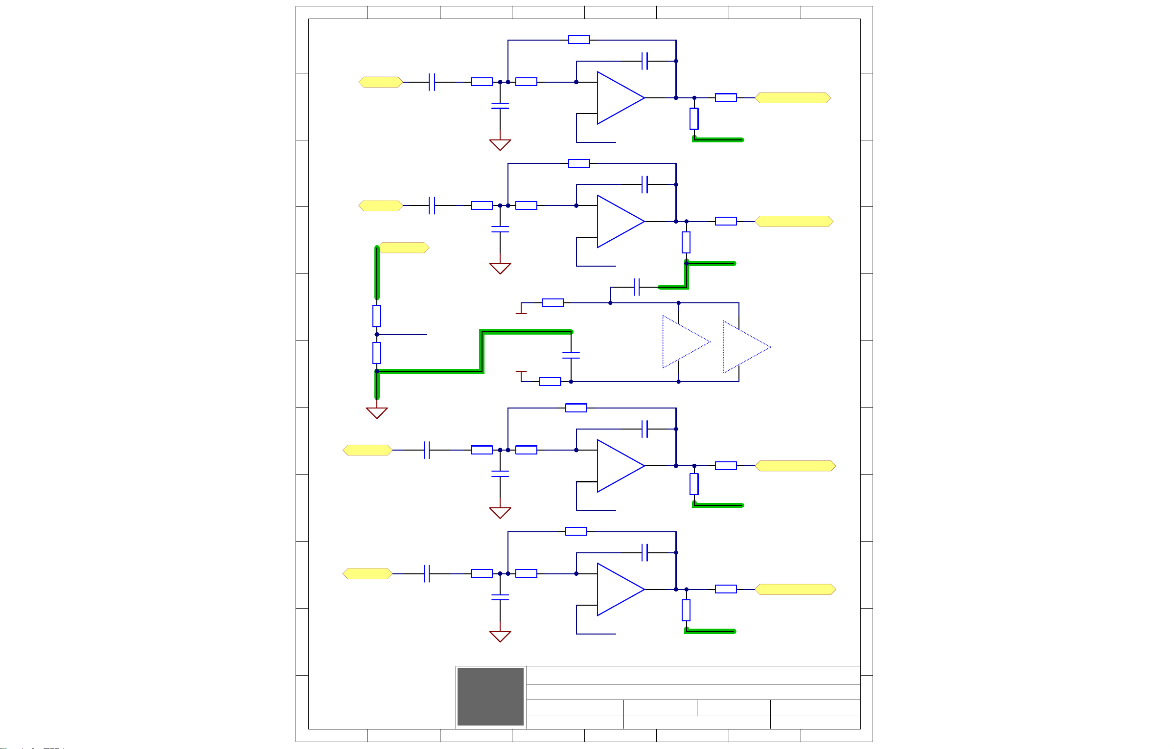
1
1
2
2
3
3
4
4
5
5
6
6
7
7
8
8
K K
J J
I I
H H
G G
F F
E E
D D
C C
B B
A A
DAC Output
Section:
Product(s):
O t t.SchDoc
8009 6 10
Sheet OfPCB#: Rev#:
Modified:
V02
File:21-J -18
RM5
EML Rev#:
01
Tmp Rev: V031
3
2
1
-
SO8
MC33078
7817
U12A
5
6
7
-
SO8
MC33078
7817
U12B
3
2
1
-
SO8
MC33078
7817
U14A
5
6
7
-
SO8
MC33078
7817
U14B
WOOFER OUTPUT
HORN OUTPUT
AGND
AGND
V
8
V-
4
SO8
MC33078
7817
U14C
L LO SIG
R LO SIG
R HI SIG
L HI SIG
12V
-12V
V
8
V-
4
SO8
MC33078
7817
U12C
100N
0805
50V
C97
22U
1210
25V
C117
100N
0805
50V
C96
W125
47R
0805
R154
W125
47R
0805
R155
+15V_4
-15V_4
R HI
L HI
R LO
L LO
Am GND
W125
3K92
0805
R23
W063
4K02
0603
R14
1N8
0805
50V
C74
220P
0805
100V
C25
W125
47K
0805
R25
W100
100R
0805
R24
AGND
22U
1210
25V
C76
W125
3K92
0805
R32
W063
4K02
0603
R28
1N8
0805
50V
C77
220P
0805
100V
C75
W125
47K
0805
R34
W100
100R
0805
R33
AGND
W125
3K92
0805
R36
W063
4K02
0603
R35
1N8
0805
50V
C83
220P
0805
100V
C81
W125
47K
0805
R38
W100
100R
0805
R37
AGND
W125
3K92
0805
R41
W063
4K02
0603
R39
1N8
0805
50V
C91
220P
0805
100V
C84
W125
47K
0805
R44
W100
100R
0805
R42
22U
1210
25V
C82
22U
1210
25V
C85
W100
19K6
0603
R16
W100
19K6
0603
R17
W100
19K6
0603
R69
W100
19K6
0603
R80
OutGnd
OutGnd
OutGnd
OutGnd
OutGnd
1K02
W100
0603
R46
W100
4K99
0805
R62
AmpGND
AmpGND
AmpGND
AmpGND
AmpGND
POR0LO
POL0LO
POR0HI
POL0HI
PIR6202
PIR6201
PIR4602
PIR4601
COC117
PIC11701PIC11702
COR23
PIR2301
COR14
PIR1401
PIR2302
PIR1402
PIC7401
COC74
PIC7402
POAMPGND
COC76
PIC7601PIC7602
COR32
PIR3201
COR62
COR46
COC82
PIC8201PIC8202
COR36
PIR3601
COC85
PIC8501PIC8502
COR41
PIR4101
COR28
PIR2801
PIR3202
PIR2802
PIC7701
COC77
PIC7702
PIR15401
PIR15501
COR35
PIR3501
PIR3602
PIR3502
PIC8301
COC83
PIC8302
COR39
PIR3901
PIR4102
PIR3902
PIC9101
COC91
PIC9102
PIR1601
PIR1701
COR154
PIR15402
COR155
PIR15502
COR69
PIR6901 PIR6902
COR80
PIR8001 PIR8002
COR16
PIR1602
PIU1202
PIU1203
COC25
PIC2501PIC2502
PIU1201
COU12A
COR17
PIR1702
PIU1206
PIU1205
COC75
PIC7501PIC7502
PIU1207
COU12B
COC97
PIC9701 PIC9702
PIC9601
COC96
PIC9602
COC81
PIC8101PIC8102
PIU1402
PIU1401
PIU1403
PIU1406
PIU1405
COU14A
COC84
PIC8401PIC8402
PIU1407
COU14B
COR24
PIR2502
COR25
PIR2501
COR33
PIR3402
COR34
PIR3401
PIU1408
COU14C
PIU1404
COR37
PIR3802
COR38
PIR3801
COR42
PIR4402
COR44
PIR4401
PIR2401PIR2402
POR0HI0SIG
PIR3301PIR3302
POL0HI0SIG
COU12C
PIU1208
PIU1204
PIR3701PIR3702
POR0LO0SIG
PIR4201PIR4202
POL0LO0SIG
Page 15

1
1
2
2
3
3
4
4
5
5
6
6
7
7
8
8
9
9
10
10
11
11
12
12
13
13
14
14
15
15
16
16
17
17
K K
J J
I I
H H
G G
F F
E E
D D
C C
B B
A A
Power Supply
Section:
Product(s):
Po erS ly.SchDoc
8009 7 10
Sheet OfPCB#: Rev#:
Modified:
V02
File:21-J -18
RM5
EML Rev#:
01
Tmp Rev:
V031
Sta by
4155
RELAY 1A
K1A
1254
2 6
1
7
5
84
3
T4
GND
GND
1000U
RADIAL
35V
C145
D1005
CDSF4148
D22
D1005
CDSF4148
D25
SB
PSgnd
5
5
W7E
5
3
W7C
5
1
W7A
5
4
W7D
5
2
W7B
S3D
DO-214AB
D4
S3D
DO-214AB
D3
S3D
DO-214AB
D1
S3D
DO-214AB
D2
S3D
DO-214AB
D7
S3D
DO-214AB
D5
S3D
DO-214AB
D8
S3D
DO-214AB
D9
GND
GRY
GRY
YEL
RED
RED
NA CH1345
120V
0V
120V
0V
WHT
BLK
BLU
GRY
GRY
RED
RED
YEL
250V 4N7
C2
CHASSIS
5
4
2
1
3
4163
-20V UNMUTE
CDSF4148
D1005
D11
W125
1M
0805
R29
18V0
SOD-323
D13
W100
10K0
0805
R30
MUTE OFF
CDSF4148
D1005
D10
W125
2K2
0805
R13
MMBT5401
7837
SOT-23
Q3
1U
4.3 3.9
50V
C40
4U7
Elec
25V
C39
Am M te
W100
18K2
0805
R43
SOT-23
MMBTA14LTIG
7701
Q4
W125
47K
0805
R45
4155
RELAY 1A
K1B
W100
10K0
0805
R31
CDSF4148
D1005
D14
+7v
+7v
-22V
22V
-44V
44V
1
2 W6A
2
1
4093
2
2 W6B
.
.
W1000
TERMINAL
7.5 BLK 18AWG 36STND D I 2 3465
W9
.
.
W1000
TERMINAL
7.5 BLK 18AWG 36STND D I 2 3465
W4
PS
3A15
2493
F1
AmG
.
.
W1000
TERMINAL
W4
.
.
W1000
TERMINAL
W9
10K0
W100
0805
R108
IEC RECT-2 i
4210
J2
W750
0R
2010
R74
W750
0R
2010
R49
W750
0R
2010
R19
TST30
TST29
TST28
TST32
TST33
TST31
8 8mm
25V100U
C21
SB -
TST40
D1005
CDSF4148
D17
D1005
CDSF4148
D20
W100
10K0
0805
R76
W100
10K0
0805
R79
W100
10K0
0805
R85
W100
10K0
0805
R90
CDSF4148
D1005
D28
10K0
W100
0805
R98
FOR NA STUFF R19 AND R74
FOR CE STUFF R49
NA
NA
CE
W063
R97
10K
4K75
W100
0805
R124
1K0
W100
0805
R111
4K75
W100
0805
R94
W125
47K
0805
R127
10K0
W100
0805
R106
4K75
W100
0805
R107
4K75
W100
0805
R129
W125
47K
0805
R126
10K0
W100
0805
R104
4K75
W100
0805
R105
HotLimit
10K0
W100
0805
R112
10K0
W100
0805
R128
W100
6K98
0805
R130
+7v+7v
SO8
LM393D
7661
1
3
2
-
U4A
LM393D
7661
7
5
6
-
U4B
SO8
V
8
V-
4
U4C
SO8
LM393D
7661
1
3
2
-
U6A
LM393D
7661
7
5
6
-
U6B
SO8
V
8
V-
4
U6C
LimitForHiTem
Sta by
M te
TST34
TST42
TST41
TST43
W125
47K
0805
R118
25V
6800U
16 35MM
C3
25V
6800U
16 35MM
C4
25V
6800U
16 35MM
C5
25V
6800U
16 35MM
C38
CE CH1345E
PIW901
COW9
COF1
PIF101 PIF102
COW90
PIW9001
PIJ201
PIW4001
PIJ202
COW40
COJ2
PIW401
COW4
COK1A
PIK102PIK103
PIW602
COW6B
PIW601
COW6A
PIC201
COC2
PIC202
PIR6601 PIR6602
COR66
COR19
PIR1901 PIR1902
COR74
PIR7401 PIR7402
PIR4902
COR49
PIR4901
COT4
PIT401
PIT402
PIT403
PIT404
COW7E
COW7D
COW7C
COW7A
COW7B
PIT405
PIT406
PIT407
PIT408
PIW705
PIW704
PIW703
PIW701
PIW702
PIR9802
COR98
COR45
PIR9801
PIU403
PIU402
PIR11102
COR111
PIR11101
PIR4501PIR4502
COU4A
PIU401
PIR12402
COR124
PIR12401
PITST3401
COTST34
PIQ401
COK1B
PIQ403
COQ4
PIQ402
PIK105
PID1402
COD14
PID1401
PIK101
PIR11201
COR112
PIR11202
PIU408
PIU405
PIU406
PIU404
PIR12801
COR128
PIR12802
COU4C
COU4B
PIU407
COU6B
COU6C
PIR10402
COR104
PIR10401
COR130
PIR13002
PIR13001
PIR9402
COR94
PIR9401
PITST4301
COTST43
PIR9701
PIR9702
COR97
PIR10602
COR106
COR127
PIR10601
PIU603
PIR12701PIR12702
PIU602
PIR12902
COR129
PIR12901
COU6A
PIU601
POSTANDBY
PIR10702
COR107
PIR10701
PITST4201
COTST42
PID2801PID2802
COD28
COR108
PIR10801 PIR10802
PIR10502
COR105
COR118
COTST41
PIR10501
PIR11801 PIR11802
PITST4101
PIU607
PIR4302
COR43
PIR4301
PIR3102
COR31
PIR3101
POHOTLIMIT
COR126
PIR12601 PIR12602
PIU608
PIU605
PIU606
PIU604
COD22
PID2201PID2202
COD17
PID1701PID1702
COD20
COD25
PID2001PID2002
PID2501PID2502
PITST2801
PIC14501
COC145
PIC14502
PIC2101
PIC2102
COD1
PID101PID102
COD3
PID301PID302
COC21
COD2
PID202
COD4
PID401
COTST28
PITST4001
COTST40
PID201
PID402
COD10
PID1001
PID1002
COD11
PID1101PID1102
POSBV0
PITST2901
COTST29
COC3
PIC301
PIC302
PIC3802
PIR1301 PIR1302
COR76
PIR7601 PIR7602
COR79
PIR7901 PIR7902
PID501PID502
COD5
COD8
COR85
PIR8501 PIR8502
COR90
PIR9001 PIR9002
COC38
PIC3801
COR13
PID1301
PID1302
PID701PID702
COD7
COD9
PID801PID802
PID901PID902
PITST3201
COTST32
PIC4002
COD13
COC40
PIC4001
PITST3001
COTST30
COR29
PIR2901
PIR3001
COR30
PIR3002
PO022V0PO044V0
PIC401
COC4
PIC402
PIC501
COC5
PIC502
PIR2902
POPSGND
PITST3101
COTST31
PIQ301
PIC3902
COC39
PIC3901
PIQ303
COQ3
PIQ302
POAMGND
PITST3301
COTST33
POAMPMUTE
Page 16

1
1
2
2
3
3
4
4
5
5
6
6
7
7
8
8
9
9
10
10
11
11
12
12
13
13
14
14
15
15
16
16
17
17
K K
J J
I I
H H
G G
F F
E E
D D
C C
B B
A A
Design Information And History
Section:
Product(s):
History.SchDoc
8009 8 10
Sheet OfPCB#: Rev#:
Modified:
V02
File:21-J -18
RM5
EML Rev#:
01
Tmp Rev: V031
CHANGE HISTORY
DESIGN HISTORY AND INFORMATION
THIS SHEET CONTAINS A CHANGE HISTORY LOG, A LIST OF THE POTS & KNOBS AND A LEADS & PINS REFERENCE SECTION.
.V01 RELEASED FOR PRODUCTION
Thermal circ it mo s. Cha e W8 9- i to 6- i l s W3 4- i or HotLimit si al to micro.
U ate layo t PDF art mbers or C3, C4, C5 a C38 to YS#5863.
.
.
.
.
.
.
.
.
.
.
V02 1
V02
.
.
.
.
.
.
.
.
.
.
07-APR-2017
13
10
7
4
1
9
11
12
8
#
2
3
5
6
VER#DATE DESCRIPTION OF CHANGE
.
.
.
.
.
.
.
.
.
01-SEP-2017
12-JUN-2018
.
PC#
.
9242
.
.
.
.
.
.
.
.
.
.
.. .
.
.
.
.
.
.
.
.
.
.
.
.
.
.
.
.
.
.
.
.
.
.
.
.
.
13
10
7
4
1
9
11
12
8
#
2
3
5
6
VER#DATE DESCRIPTION OF CHANGE
.
.
.
.
.
.
.
.
.
.
.
.
PC#
.
.
.
.
.
.
.
.
.
.
.
.
.. .
.
.
.
.
.
.
.
.
.
.
.
.
.
.
.
.
.
.
.
.
.
.
.
.
.
13
10
7
4
1
9
11
12
8
#
2
3
5
6
VER#DATE DESCRIPTION OF CHANGE
.
.
.
.
.
.
.
.
.
.
.
.
PC#
.
.
.
.
.
.
.
.
.
.
.
.
Page 17

1
1
2
2
3
3
4
4
5
5
6
6
7
7
8
8
9
9
10
10
11
11
12
12
13
13
14
14
15
15
16
16
17
17
K K
J J
I I
H H
G G
F F
E E
D D
C C
B B
A A
Assembly Documentation
Section:
Product(s):
Assembly.SchDoc
8009 9 10
Sheet OfPCB#: Rev#:
Modified:
V02
File:21-J -18
RM5
EML Rev#:
01
Tmp Rev: V031
THIS SHEET CONTAINS SPECIAL PRODUCTION NOTES AND A LIST OF PCB HARDWARE PARTS REQUIRED FOR THE BUILD.
SCREWS AND BOLTS STANDOFFSNUTS
PCB HARDWARESPECIAL PRODUCTION NOTES
MISCELLANEOUS
PCB ASSEMBLY DOCUMENTATION
1. Do ot be tra s ormer lea s o T1 YS# 1254.
2. A ly RTV to all tall ca s a a ro riate areas.
3. For North America (M1705) st R19 a R74.
For CE (M1203) st R49 a o ot st R19 a R74.
4. Use i a c tter here ossible to se arate cb rom a el.
POTENTIOMETERS AND KNOBS
"STYLE_P32"
P1
S1
S2
S3
90864453
4200
3522
3439
.
.
.
.
.
.
.
.
9086
9089
9088
.
.
.
.
.
.
.
.
LEVEL
REF POT/SW YS#FUNCTION KNOB#
POTENTIOMETERS/SWITCHES AND KNOBS
BT Mo e
.
.
.
.
.
.
.
.
MODE
O O
.. .
.
.
.
.
.
.
.
.
.
STYLE
P40
ROT3
.
.
.
.
.
.
.
.
.
.
9089
9088
Cannot open file D:\RM5 IP RTV.jpg
Cannot open file D:\RM5 AC RTV.jpg
Page 18

1
1
2
2
3
3
4
4
5
5
6
6
7
7
8
8
9
9
10
10
11
11
12
12
13
13
14
14
15
15
16
16
17
17
K K
J J
I I
H H
G G
F F
E E
D D
C C
B B
A A
ECAD Incidentals
Section:
Product(s):
ECO.SchDoc
8009 10 10
Sheet OfPCB#: Rev#:
Modified:
V02
File:21-J -18
RM5
EML Rev#:
01
Tmp Rev: V031
PANEL PARTS
Corners
Panel Fiducials
Tooling Holes
Clinch Origin
BEC LOC
TLH1
TLH2 TLH3
Insert Origin
TLH4
TLH5
CNR1 CNR2 CNR3 CNR4
PF1 PF2 PF3 PF4
CRG1
M1203 RM5CE
INS1
Bla Si e - 285.000mm 152.000mm(11220 5984)
VCD 2 HOLE
INS2
See PcbDoc for default clearance rules.
Note: You must define your own rules for -HI and +HI.
PCB Title
Ste & Re eat 1 1.234Y1 123.4
1
1.234
1
123.4
HW17
2335
HW18
2335
HW20
2335
HW19
2335
HW22
HW10
HW12
HW21
HW24
2335
HW23
2335
HW25
2335
PCB
AI-ASSY
DOCUMENTATION
Blank PCB
AI Sub-Assembly
Fi ePitchU8
Room1
Fi ePitchU10
Room2
I oreAC
Room3
I oreAC 1
Room4
BRK1
BRK2
BEC1
COCNR1
COCNR2
COPF1 COPF2 COPF3 COPF4
COCNR3 COCNR4
COTLH2 COTLH3 COTLH4
COTLH1
COCRG1
COINS1
COTLH5
COINS2
COBRK2
COBRK1
COPCB
COAI0ASSY
COHW22
COHW10
COHW12
COHW21
COHW17
CORoom3
COHW23
COHW24
COHW25
CORoom1
CORoom2
CORoom4
COHW19
COBEC1
COHW20
COHW18
Page 19

Score
Score
6800U 25V
C5
6800U 25V
C4
W1 3
R90
10K0
5863
5863
3 5 3 8
R85
10K0
5863
6800U 25V
C3
6800U 25V
10K0
R79
10K0
R76
5863
C38
D5
D8
4162
S3D
10K0
R30
C39
S3D
D13
18V0
4U7
W6
D3
D1
7837
Q3
W7
D10
4148
4148
2K2
1M
D11
R13
R29
4148
47K
R45
R128
HC3
K1
4155
7701
1K0
LM393D
10K0
Q4
D14
10K
4K75
10K0
U4
R111
R97
R88
D9
D4
4163
S3D S3D
D7
S3D S3D
D2
S3D S3D
1U
C40
R49
0R
Match -F
i mbers
to these # s
D17
R106
D25
10K0
4K75
10R
10R
R84
4148
C21
R104
10K0
4K75
R105
U6
R94
D28
47N
C54
C52
47N
R4
8 7 6 5
100U
R118
R126
R130
47K
47K
6K98
LM39 3D
47K
R127
4K75
4148
10R
R93
10R
R91
C55
47N
R124
R98
R87
10K0
R112
10R
10R
4148
R107
C53
47N
1254
C145
D6
R31
R43
10K0
18K2
R129
4K75
R108
10K0
R96
1000U 35V
5635
D29
4148
4148
2337
R95
10R
10R
C41
W1000
3A15
F1
W9
W4
W1000
645 1
4N7 250V
C2
T4
4148
4148
D22
D20
W1
D23
4148
4148
D26
0R0
M1203RM5CE
BT Ctrl
Bl Th
Pot T
Pot W
STBY
Bl Th
Mo e B
Mo e A
M teS
Po er
R169
100R
LED
GND
LED
LD2
Bl T th
LD8
SW
Po er
100R
Mo e
S1
P1
S2
R215
47U
100N
C32
2381
3522
T ist Le .
4200
T ist Le .
Le el
Bl T th
3439
S3
W1 0
LD3
Po er
100R
R119
4453
R44
R42
R38
R37
R62
R33
R34
W8
100R
R155
LD4
47R
R151
R120
R150
U16
C89
47R
MC33078
100N
100N
C90
2337
W1 4
47U
C43
W3
W8
BT St
U13
47R
47R
2370
R154
C56
W3
100N
100N
LED1
2327
100R
R70
W1 0
2358
R121 C59
C61
R24
4K99
1U
1U
C34
10K0
C103
100N
1M
R47
100R
100R
4K99
100R
R68
64K9
220P
C134
47K
47K
47K
C97
7837
BM23
47R
2327
6535
4194
W15
R164
R116
4K75
C96
100N
4K02
1N8
19K6
19K6
1N8
MC33 078
220P
1K02
R28
R14
R60
64K9
64K9
R8
10K0
Q11
1U
MC33 078
R32
C77
C74
R23
C24
47R
47R
R40
7837
R11
1U
C36
C23
R10
C76
C117
R123
C14
19K6
19K6
0R0
R3
R15
10K0
R137
100N
100N
1K0
C37
1K0
220P 220P
220P
18K2
10U
L2
R27
4K02
4K02
1N8
1N8
4K02
R80
R69
10U
100N
R9
0R0
C12
100N
Q1
600R
C 3 3
C 2 2
100N
100R
7805
C35
U14
R46
100N
47K
R25
U12
C75
R17
R16
C25
D24
8V2
D21
8V2
R75
4K99
R81
R122
4148
D15
10K0
R102
D18
C26
4148
4148
D19
Slee
Q6
C60
10U
10U
C195
R274
47R
DNS
R114
47R
R110
3K92
3K92
3K92
3K92
R41
R39
C84
C91
C83
R36
C81
R35
C20
C19
C9
C10
U2
ADAU1701
100N
1K0
220N
C17
U3
UART1 T
C31
100N
MKL15Z64VLH4
100N
Micro
R117
47R
22U
22U
22U
22U
C85
C82
100N
100N
C6
600R
Q2
W2
L3
11.2896
D27
R48
D12
C18
10U
10U
100N
C13
47R
R12
BT
4148
4R7
MBRA340
120 H
L5
10U
C50
100U
C49
10U
475R0
3N3
100N
100N
C16
R5
R7
R21
47R
C30
100N
C7
10U
100N
C8
47R
47R
475R0
C44
15U
C42
U5
10N
LM26 71
2K2
C51
47P
R20
L1
2.2UH
C11
R2
C15
DNS
R22
47R
C29
1U
100N
47R
1U
C1
10U
W11
LM111 7-5
600R
L4
U1
C27
R26
N 1
N 2
C28
R1
W5
C87
J4
J1
4K02
R77
R54
R61
R71
4K02
4K02
4K02
470P
4090
J3
4090
R51
1K02
R89
100R 10K0
100R
10K0
R125
R100 R86
470P
C86
1K02
470P
11K0
11K0
R99
R101
R103
4186
Stereo I
J2
6548
C99
470P
C102
4K99
R221
1K02
R214
BAL LINE IN-L
1K02
R213
R55
4K99
C100
220P
MC33079D
4K99
R82
4K99
R83
100N
C57
BAL LINE IN-R
C88
100N
2370
S4
C110
4K99
R78
4K99 4K9 9
R67
4210
470P
470P
1K02
1K02
4K99
220P
4K99
4K99
R216
C112
R222
R73
R65
R72
C111
U18
R92
W14
W9
W1000
W1000
W4
Score
2mm Ra - 4 Places
Score
Score
Score
Score
Page 20

1
SPECIA
PRODUCTION NOTES
A A
2
3
4
5
6
7
8
9
10
11
12
13
14
15
16
17
PCB ASSEMBLY DOCUMENTATION
Cannot open file D:\RM5 AC RTV.jpg
B B
PCB HARDWARESPECIAL PRODUCTION NOTES
1. Do ot be tra s ormer lea s o T1 YS# 1254.
SCREWS AND BOLTS STANDOFFSNUTS
MISCELLANEOUS
2. A ly RTV to all tall ca s a a ro riate areas.
C C
3. For North America (M1705) st R19 a R74.
For CE (M1203) st R49 a o ot st R19 a R74.
4. Use i a c tter here ossible to se arate cb rom a el.
D D
E E
Cannot open file D:\RM5 IP RTV.jpg
F F
9089
POTENTIOMETERS AND KNOBS
POTENTIOMETERS/SWITCHES AND KNOBS
G G
H H
P1
S1
S2
S3
.
.
.
.
.
.
.
.
LEVEL
MODE
O O
BT Mo e
.
.
.
.
.
.
.
.
4200
3522
3439
.
.
.
.
.
.
.
.
.
I I
REF POT/SW YS#FUNCTION KNOB#
STYLE
P40
ROT3
.
.
.
.
.
.
.
.
.
.
90864453
9086
9089
9088
.
.
.
.
.
.
.
.
.. .
9088
"STYLE_P32"
J J
Section:
K K
Product(s):
THIS SHEET CONTAINS SPECIAL PRODUCTION NOTES AND A LIST OF PCB HARDWARE PARTS REQUIRED FOR THE BUILD.
1
2
3
4
5
6
7
8
9
10
11
12
13
Modified:
14
Assembly Documentation
RM5
8009 1 9
15
V02
Assembly.SchDoc
File:12-J -18
EML Rev#:
16
01
Sheet OfPCB#: Rev#:
Tmp Rev: V031
17
Page 21

1
A A
2
3
4
5
6
7
8
9
10
11
12
13
14
15
16
17
DESIGN HISTORY AND INFORMATION
B B
CHANGE HISTORY
C C
D D
E E
F F
G G
07-APR-2017
1
2
01-SEP-2017
3
12-JUN-2018
4
.
5
.
6
.
7
.
8
.
9
.
10
.
11
.
12
.
13
.
#
.
1
2
.
3
.
4
.
5
.
6
.
7
.
8
.
9
.
10
.
11
.
12
.
13
.
#
.
1
2
.
3
.
4
#
10
11
12
13
.
5
.
6
.
7
.
8
.
9
.
.
.
.
.
H H
I I
VER#DATE DESCRIPTION OF CHANGE
PC#
.V01 RELEASED FOR PRODUCTION
V02 1
.
V02
9242
.
.
.
.
.
.
.
.
.
.
.
.
.
.
.
.
.
.
.
.
VER#DATE DESCRIPTION OF CHANGE
PC#
Thermal circ it mo s. Cha e W8 9- i to 6- i l s W3 4- i or HotLimit si al to micro.
U ate layo t PDF art mbers or C3, C4, C5 a C38 to YS # 5 8 6 3 .
.
.
.
.
.
.
.
.
.
.
.. .
.
.
.
.
.
.
.
.
.
.
.
.
.
.
.
.
.
.
.
.
.
.
.
.
VER#DATE DESCRIPTION OF CHANGE
PC#
.
.
.
.
.
.
.
.
.
.
.
.
.. .
.
.
.
.
.
.
.
.
.
.
.
.
.
.
.
.
.
.
.
.
.
.
.
.
.
.
.
.
.
.
.
.
.
.
.
.
J J
Section:
THIS SHEET CONTAINS A CHANGE HISTORY LOG, A LIST OF THE POTS & KNOBS AND A LEADS & PINS REFERENCE SECTION.
K K
1
2
3
4
5
6
7
8
9
10
11
12
13
Product(s):
Modified:
14
Design Information And History
RM5
8009 9 9
15
History.SchDoc
File:12-J -18
V02
EML Rev#:
16
01
Sheet OfPCB#: Rev#:
Tmp Rev: V031
17
Page 22

1
1
2
2
3
3
4
4
5
5
6
6
7
7
8
8
9
9
10
10
11
11
12
12
13
13
14
14
15
15
16
16
17
17
K K
J J
I I
H H
G G
F F
E E
D D
C C
B B
A A
Product(s):
M1494 1 6Sheet OfPCB#: Rev#: V02
Powered Studio Monitor
Description:
RM5
Yorkville Sound Ltd.
550 Granite Court
Pickering, ON
Canada L1W 3Y8
www.yorkville.com
EML Rev#: 01
To Sheet.SchDoc
Modified: File:
2018-02-06
Tmp Rev:
V031
ASSEMBLY NOTES
Assembly.SchDoc
DESIGN HISTORY
History.SchDoc
AmpMute
-44V_
+44V_
TWT-Out+
WFR-Out+
SGnd
TWT-In+
WFR-In+
-22V_
+22V_
-22VT
+22VT
A
A
Power_Amp.SCHDOC
LT+
LW+
2620W1 20
26
18
W1 18
26
19
W1 19
26
21
W1 21
26
22
W1 22
26
23
W1 23
26
24
W1 24
26
26
W1 26
-12Vout
+12Vout
+22V
-22V
PAmpGnd
LV
LV_PowerSupply.SchDoc
AmpMute
-44V_
+44V_
TWT-Out+
WFR-Out+
SGnd
TWT-In+
WFR-In+
-22V_
+22V_
-22VT
+22VT
B
B
Power_Amp.SCHDOC
RT+
RW+
26
17
W1 17
26
16
W1 16
-22VT
+22VT
26
11
W1 11
26
8
W1 8
26
12
W1 12
26
14
W1 14
26
13
W1 13 267W1 7
26
15
W1 15
26
25
W1 25
26
9
W1 9
26
10
W1 10
26
6
W1 6
26
4
W1 4
26
5
W1 5
26
3
W1 3
26
2
W1 2
26
1
W1 1
+12Vout
-12Vout
RM5 Am li ier - To Sheet
PIW1026
PIW1024
PIW1025
PIW1016
PIW1017
PIW1015
PIW101
PIW102
COW1:1
COW1:2
PIW103
PIW108
COW1:3
COW1:8
COW1:26
COW1:24
PIW109
COW1:9
COW1:25
COW1:16
COW1:17
COW1:15
PIW1014
PIW1011
PIW1013
PIW106
PIW104
PIW1022
PIW1020
PIW1018
COW1:6
COW1:4
COW1:22
COW1:20
COW1:18
PIW1010
PIW1012
COW1:10
PIW107
PIW105
PIW1023
PIW1021
PIW1019
COW1:23
COW1:21
COW1:19
COW1:7
COW1:5
COW1:12
COW1:14
COW1:11
COW1:13
Page 23

1
1
2
2
3
3
4
4
5
5
6
6
7
7
8
8
K K
J J
I I
H H
G G
F F
E E
D D
C C
B B
A A
LV Power Supply
Section:
Product(s):
LV Po erS ly.SchDoc
M1494 1 6
Sheet OfPCB#: Rev#:
Modified:
V02
File:2018-02-06
RM5
EML Rev#:
01
Tmp Rev:
V031
15K0
W100
0805
R5
SOD-323
12V0
D1
DPAK-3
MJD122
7015
Q1
-12Vo t
12Vo t22V
-22V
15K0
W100
0805
R9
SOD-323
12V0
D2
10R0
W125
0805
R3
10R0
W125
0805
R12
DPAK-3
MJD127
7014
Q4
i
NetClass
Gro s
PAm G
MMBT5401
SOT-23
7837
Q3
SOT-23
MMBT3904
7838
Q2
W100
301R
0805
R4
W100
301R
0805
R8
50V1U
3.3mm
C7
50V1U
3.3mm
C5
10R0
W125
0805
R7
10R0
W125
0805
R10
LV Po er S ly
PO022V
POPAMPGND
COR5
PIR501 PIR502
COR9
PIR901 PIR902
PIC501
PIC502
COQ1
PIQ102
PIQ103
PIQ101
PIQ203
COC5
PIQ202
PIQ302
PIC701
COC7
PIC702
PIQ303
PIQ401
PIQ402 PIQ403
COQ4
COQ2
PIQ201
COQ3
PIQ301
PIR701
PIR301
PID102
COD1
PID101
PIR402
COR4
PIR401
PIR802
COR8
PIR801
PIR1001
PID202
COD2
PID201
PIR1201
COR7
PIR702
COR3
PIR302
COR10
PIR1002
COR12
PIR1202
PO012VOUT
Page 24

1
1
2
2
3
3
4
4
5
5
6
6
7
7
8
8
9
9
10
10
11
11
12
12
13
13
14
14
15
15
16
16
17
17
K K
J J
I I
H H
G G
F F
E E
D D
C C
B B
A A
Power Amp
Section:
Product(s):
Po er Am .SCHDOC
M1494 2 6
Sheet OfPCB#: Rev#:
Modified:
V02
File:
2018-02-06
RM5
EML Rev#: 01
Tmp Rev:
V031
W125
5K76
0805
R232
W125
0805
30K0
R102
50V
100P
C62
50V
27P
C53
W125
10R0
R98
250V
SOT-23
D41
W333
33R
R99
W125
0805
30K0
R227
W125
2K2
R231
W125
2K2
R118
W125
5K76
0805
R119
50V
330P
C95
W100
1K0
R246
100V
47P
C69
MC33078
SO8
3
2
1
-
U23 1
W100
1K0
R166
MC33078
SO8
3
2
1
-
U8 1
W100
2K74
R64
50V
100N
0805
C67
W125
47R
R230
50V
100N
0805
C49
W125
47R
R45
W100
15K0
R248
50V1N
0805
C65
W125
10R0
R228
W100
15K0
R156
W125
47R
R197
50V1N
0805
C3
50V1N
0805
C50
W125
30K0
0805
R116
W125
49K9
0805
R144
W250
1206
330R
R251
25V100U
ELE 8mm
C66
W333
33R
R229
W250
1206
330R
R200
250V
SOT-23
D34
W250
1206
330R
R190
25V100U
ELE 8mm
C51
15V0
SOD-323
ZD6
W125
47R
R247
1W00
0R047
2512
R237
1W00
0R047
2512
R234
15V0
SOD-323
ZD3
50V
5N6
C59
W125
47R
R48
16V10U
Elec
C71
16V10U
Elec
C60
W100
2K74
R224
50V1N
0805
C70
W125
10R0
R244
W125
49K9
0805
R242
W125
10R0
R145
25V100U
ELE 8mm
C72
W333
33R
R245
25V100U
ELE 8mm
C38
W333
33R
R146
W125
47R
R225
50V
5N6
C2
W125
47R
R162
16V10U
Elec
C4
16V10U
Elec
C64
50V
1N
C68
50V
1N
C52
W100
100R
R252
12V0
SOD-323
ZD4
MC33078
SO8
84
V
V-
U23 3
15V0
SOD-323
ZD5
250V
SOT-23
D33
W100
100R
R223
250V
SOT-23
D32
MC33078
SO8
5
6
7
-
U8 2
12V0
SOD-323
ZD1
12V0
SOD-323
ZD2
SOT-23
MMBTA64
8022
Q23
MC33078
SO8
84
V
V-
U8 3
250V
SOT-23
D24
MURA240T3
403D
D37
MURA240T3
403D
D35
1W00
0R047
2512
R115
1W00
0R047
2512
R141
W100
15K0
R240
W100
15K0
R153
W125
47R
R249
250V
SOT-23
D42
W125
470R
R243
MC33078
SO8
5
6
7
-
U23 2
W125
470R
R143
MJD127
DPAK-3
7014
Q32
MJD122
DPAK-3
7015
Q28
MJD122
DPAK-3
7015
Q21
MJD127
DPAK-3
7014
Q25
IRF530NS
D2PAK
7840
G
D
S
Q26
IRF9530NS
D2PAK
7839
G
D
S
Q33
NET00035
W250
1206
330R
R47
W250
1206
330R
R46
W250
1206
330R
R196
W250
1206
330R
R199
W250
1206
330R
R250
CDSF4148
D1005
D30
CDSF4148
D1005
D38
SOT-23
MMBF4391LT1
7806
S
D
Q30
SOT-23
MMBF4391LT1
7806
S
D
Q24
301R
W100
0805
R114
5K76
W125
0805
R226
TP3
TP4
Desi ator
TP1
TP2
Horn Bias Set to 1.5mV
Woofer Bias Set to 1.5mV
Between TP1Ch and TP2Ch
Woofer Amp
Tweeter Amp
SOT-23
MMBTA64
8022
Q29
B
10K
Bias
4512
P2
B
10K
Bias
4512
P3
1W00
0R047
2512
R236
MJD127
DPAK-3
7014
Q31
MJD122
DPAK-3
7015
Q27
1W00
0R047
2512
R233
-44V
Am M te
44V
TWT-I
WFR-I
WFR-O t
TWT-O t
SG
22V
-22V
-22V
-44V
+22V
+44V
AmpMute
WFR-In+
TWT-In+
W125
47R
R1
W125
47R
R2
0R
W250
R6
22VT
-22VT
Po er Am
Ch Amps
10R0
W125
0805
R11
Between TP3Ch and TP4Ch
W125
30K0
0805
R235
SGND
SGND
SGND
SGND
SGND
5N6
0805
50V
C1
1N
0805
50V
C6
W125
33R
0805
R13
COR114
POTWT0IN0
PIR11401 PIR11402
PIQ2403
PIQ2402
PIQ2401
COQ24
COC4
PIC401PIC402
PIR11902
PIR11901
POSGND
POWFR0IN0
POAMPMUTE
COR11
PIR1101 PIR1102
PIQ3002
PIQ3003
PIQ3001
COC64
PIC6401PIC6402
COQ30
COR102
PIR10201
COR119
PIC6002
COR226
PIR22601
PIR23202
COR232
PIR23201
PIR10202
PIR11802
COR118
PIR11801
COC52
COC60
PIC6001
PIC5201PIC5202
COR153
PIR15301 PIR15302
COR227
PIR22602
PIR22701
PIC7102
PIR22702
COC71
PIC7101
PIR23102
COR231
PIR23101
COC68
COR240
PIR24001 PIR24002
PIC6801PIC6802
PIU805
PIU806
PIR6401
PIC5302
PIC6202
PIU2305
PIU2306
COR64
PIR6402
COU8:2
COC53
PIC5301
COR166
PIR16601
PIR16602
COC62
PIC6201
COR224
PIR22401 PIR22402
COU23:2
COC69
PIC6902
COR246
PIR24601
COC95
PIU807
PIC6901
PIR24602
PIC9501PIC9502
COR45
PIR4501 PIR4502
PIC4901
PIC4902
COC49
PIQ2302
COQ23
PIQ2303
PIU803
COD30
PID3002
PID3001
PIU802
PIQ2301
PIR14302
COR143
PIR14301
COC1
PIU2307
PIC101PIC102
COR230
PIR23001 PIR23002
COC67
PIQ2902
COQ29
PIC6701
PIC6702
PIQ2903
PIR24302
PIR24301
PIU2303
COD38
PID3802
PID3801
PIU2302
PIP201
PIP202
PIP203
PIR11602
PIR11601
PIR14402
PIR14401
COU8:1
PIP302
PIQ2901
COR243
COP2
COR116
COR144
COR156
PIR15601PIR15602
COR197
PIR19701 PIR19702
PIU801
PIP301
COP3
PIP303
PIR23502
COR235
PIR23501
PIR24202
COR242
COR248
PIR24201
COU23:1
PIU2301
COR98
PIR9801 PIR9802
PIC301
COC3
PIC302
PIC5001
COC50
PIC5002
COR145
PIR14501
PIR22801 PIR22802
PIC6501
PIC6502
PIC7001
PIC7002
PIR24401 PIR24402
PIR24801PIR24802
COR249
PIR24901 PIR24902
COR228
COC65
COC70
COR244
PIR14502
PID2402
COD24
PID2401
COR99
PIR9901 PIR9902
PIU808
PIU804
COU8:3
COR146
PIR14601 PIR14602
COD32
PID3202
PID3201
COD33
PID3302
PID3301
COR229
PIR22901 PIR22902
PIU2308
COU23:3
PIU2304
COR245
PIR24501
PIR24502
COD42
PID4202
PID4201
COR46
PIR4601
PIC3801
COC38
PIC3802
PIC5101
COC51
PIC5102
COR199
PIR19901 PIR19902
COD34
PID3401PID3402
PIC6601
COC66
PIC6602
PIC7201
COC72
PIC7202
PID4101
PID4102
COD41
COR250
PIR25001
PIZD102
COZD1
PIZD101
PIZD202
COZD2
PIZD201
COR190
PIR19001
PIR19002
COR200
PIR20001 PIR20002
COR1
PIR101
COR225
PIR22501 PIR22502
PIZD402
COZD4
PIZD401
PIZD502
COZD5
PIZD501
COR247
PIR24701
COR2
PIR201
COR251
PIR25002
PIR25101
COR48
PIR4801 PIR4802
COC2
PIC202
COC59
PIC5902
COR162
PIR16201 PIR16202
COR196
PIR19601
COR223
PIR22301 PIR22302
PIR102
COQ27
PIR24702
PIR202
PIR25102
PIR25201
PIR4602
PIC201
PIC5901
PIR19602
PIQ2701
PIQ3101
COR252
PIR25202
COR47
PIR4701
PIR4702
PIQ2101
PIQ2501
PIC601 PIC602
PIZD302
COZD3
PIZD301
PIQ2702
PIQ2703
PITP301
COTP3
PIR23302
COR233
PIR23301
PIR23602
COR236
PIR23601
PITP401
COTP4
PIQ3103
COQ31
PIQ3102
PIZD602
COZD6
PIZD601
PO022VT
PIQ2102
COQ21
PIQ2103
PITP101
COTP1
PIR11502
COR115
PIR11501
PIR14102
COR141
PIR14101
PITP201
COTP2
PIQ2503
COQ25
PIQ2502
PIR1302
COC6
PIR1301
PIQ2601
COR13
PIQ2801
PIQ3201
PIQ3301
PIQ2602
PIQ2603
PID3502
PIQ2802
PIQ2803
PIR23402
COR234
PIR23401
PIR23702
COR237
PIR23701
PIQ3203
PIQ3202
PIQ3303
PIQ3302
COQ26
COD35
PID3501
COQ28
COQ32
COD37
PID3701PID3702
COQ33
POTWT0OUT0
PO044V0
PO022V0
POWFR0OUT0
COR6
PIR601
Page 25

1
1
2
2
3
3
4
4
5
5
6
6
7
7
8
8
9
9
10
10
11
11
12
12
13
13
14
14
15
15
16
16
17
17
K K
J J
I I
H H
G G
F F
E E
D D
C C
B B
A A
Design Information And History
Section:
Product(s):
History.SchDoc
M1494 1 6
Sheet OfPCB#: Rev#:
Modified:
V02
File:
2018-02-07
RM5
EML Rev#: 01
Tmp Rev:
V031
CHANGE HISTORY POTENTIOMETERS AND KNOBS
DESIGN HISTORY AND INFORMATION
THIS SHEET CONTAINS A CHANGE HISTORY LOG, A LIST OF THE POTS & KNOBS AND A LEADS & PINS REFERENCE SECTION.
.V01 RELEASED V01
FOR DETAILS SEE PC AND ASSEMBLY PAGE
PC IMPLEMENTED ON BOARD
.
.
.
.
.
.
.
.
.
.
.
V02
.
.
.
.
.
.
.
.
.
.
13-APR-2017
13
10
7
4
1
9
11
12
8
#
2
3
5
6
VER#DATE DESCRIPTION OF CHANGE
.
.
.
.
.
.
.
.
.
22-JAN-2018
06-FEB-2018
.
PC#
9151
9151
.
.
.
.
.
.
.
.
.
.
.. .
.
.
.
.
.
.
.
.
.
.
.
.
.
.
.
.
.
.
.
.
.
.
.
.
.
13
10
7
4
1
9
11
12
8
#
2
3
5
6
VER#DATE DESCRIPTION OF CHANGE
.
.
.
.
.
.
.
.
.
.
.
.
PC#
.
.
.
.
.
.
.
.
.
.
.
.
.. .
.
.
.
.
.
.
.
.
.
.
.
.
.
.
.
.
.
.
.
.
.
.
.
.
.
13
10
7
4
1
9
11
12
8
#
2
3
5
6
VER#DATE DESCRIPTION OF CHANGE
.
.
.
.
.
.
.
.
.
.
.
.
PC#
.
.
.
.
.
.
.
.
.
.
.
.
REF POT/SW YS#FUNCTION KNOB#
POTENTIOMETERS/SWITCHES AND KNOBS
STYLE
Page 26

TP4B
TP3 B
TP2 B
TP1 B
TP1A
TP2A
TP3 A
TP 4A
Bias
P3A
Bias
P2A
Bias
P2B
Bias
P3B
3
2
1
TP4B
TP3 B
TP2 B
TP1 B
TP1A
TP2A
TP3 A
TP 4A
Bias
P3A
Bias
P2A
Bias
P2B
Bias
P3B
3
2
1
C72A
C66A
C51A
C38A
C38B
C51B
C66B
C72B
D38A
R13B
R13A
C6B
C6A
R11B
R11A
R6A
R6B
D30A
U23B
D38B
C7
C5
R12
R9
R8
R5
R4
R3
Q4
Q3
Q1
D2
D1
ZD6B
ZD5B ZD4B
ZD3B
ZD2B
ZD1B
U8B
R252B
R251B
R250B
R249B
R248B
R247B
R246B
R245B
R244B
R243B
R242B
R240B
R237B
R236B
R235B
R234B
R233B
R232B
R231B
R230B
R229B
R228B
R227B R226B
R225B
R224B
R223B
R200B
R199B
R197B
R196BR190B
R166B
R162B
R156B
R153B
R146B
R145B
R144B
R143B
R141B
R119B
R118B
R116B
R115B
R114B
R102B
R99B
R98B
R64B
R48B
R47BR46B
R45B
Q33B
Q32BQ31B
Q30B
Q29B
Q28BQ27B
Q25B
Q24B
Q23B
Q21B
D42B
D41B
D37B
D35B
D34B
D33B
D32B
D24B
C95B
C71B
C70B
C69B
C68B
C67B
C65B
C64B
C62B
C60B
C59B
C53BC52B
C50B
C49B
C4B
C3B
C2B
C2A
C3A
C4A
C49A
C50A
C52A
C53A
C59A
C60A
C62A
C64A
C65A
C67A
C68A
C69A
C70A
C71A
C95A
D24A
D33A
D34A
D35A
D37A
D41A
D42A
Q21A
Q23A
Q24A
Q25A
Q26A
Q27A
Q28A
Q29A
Q30A
Q31AQ32A
Q33A
R45A
R46AR47A
R48A
R64A
R98A
R99A
R102A
R114A
R115A
R116A
R118A
R119A
R141A
R143A
R144A
R145A
R146A
R153A
R156A
R162A
R166A
R190AR196A
R197A
R199A
R200A
R223A
R224A
R225A
R226AR227A
R228A
R229A
R230A
R231A
R232A
R233A
R234A
R235A
R236A
R237A
R240A
R242A
R243A
R244A
R245A
R246A
R247A
R248A
R249A
R250A
R251A
R252A
U8A
U23A
ZD1A
ZD2A
ZD3A
ZD4A
ZD5A
ZD6A
R1B
R1A
R2B
R2A
Q26B
D32A
R7
R10
C1A
C1B
Q2
D30B
7883
220U
220U
220U
220U
220U
220U
220U
220U
4148
33R
33R
1N
1N
10R0
10R0
0R
0R
4148
MC33078
4 1 4 8
1U
1U
10R0
15K 0
301R
15K0
301R
10R0
MJD127
T5401
MJD122
12V0
12V0
15V0
15V0
12V0
15V0
12V0
12V 0
MC33078
TP
TP
TP TP
100R
330R
330R
47R
15K0
47R
1K0
33R
10R0
470R
49K9
15K0
0R047
0R047
30K0
0R047
0R047
5K76
2K2
47R
33R
10R0
30K0 5K76
47R
2K74
100R
330R
330R
47R
330R330R
1K0
47R
15K0
15K0
33R
10R0
49K9
470R
0R047
5K76
2K2
30K0
0R047
301R
30K0
33R
10R0
2K74
47R
330R330R
47R
IRF9530NS
MJD127
MJD127
439 1LT1
MMBTA64
MJD122
MJD122
MJD127
439 1LT1
MMBTA64
MJD122
250 V
250V
240T3
240T3
250V
250V
250V
250V
330P
10U
1N
47P
1N
100N
1N
10U
100P
10U
5N6
27P
1N
1N
100N
10U
1N
5N6
5N6
1N
10U
100N
1N
1N
27P
5N6
10U
100P
10U
1N
100N
1N
47P
1N
10U
330P
250V
250 V
250 V
240T3
240T 3
250V
250 V
MJD122
MMBTA64
4391LT1
MJD127
IRF530NS
MJD122
MJD122
MMBTA64
439 1LT 1
MJD127
MJD127
IRF9530NS
47R
330R330R
47R
2K74
10R0
33R
30K0
301R
0R047
30K0
2K2
5K76
0R047
470R
49K9
10R0
33R
15K0
15K0
47R
1K0
330R330R
47R
330R
330R
100R
2K74
47R
5K7630K0
10R 0
33R
47R
2K2
5K76
0R047
0R047
30K0
0R047
0R047
15K0
49K 9
470 R
10R 0
33R
1K0
47R
15K0
47R
330R
330R
100R
TP
TP
TP
TP
MC33078
MC33078
12V0
12V0
15V0
12V0
15V0
15V0
47R
47R
47R
47R
IRF530NS
250 V
10R0
10R0
5N6
5N6
T3904
4148
Page 27

1
1
2
2
3
3
4
4
5
5
6
6
7
7
8
8
9
9
10
10
11
11
12
12
13
13
14
14
15
15
16
16
17
17
K K
J J
I I
H H
G G
F F
E E
D D
C C
B B
A A
Assembly Documentation
Section:
Product(s):
Assembly.SchDoc
M1494 1 6
Sheet OfPCB#: Rev#:
Modified:
V02
File:
2018-02-26
RM5
EML Rev#: 01
Tmp Rev:
V031
THIS SHEET CONTAINS SPECIAL PRODUCTION NOTES AND A LIST OF PCB HARDWARE PARTS REQUIRED FOR THE BUILD.
SCREWS AND BOLTS STANDOFFSNUTS
PCB HARDWARE
SPECIAL PRODUCTION NOTES
MISCELLANEOUS
PCB ASSEMBLY DOCUMENTATION
1. HAND PLACE CONNECTOR W1 (#7883) BEFORE THE REFLOW OVEN.
2. USE PIZZA CUTTER TO SEPERATE BOARDS FROM PANEL.
PCB
AI-ASSY
DOCUMENTATION
Blank PCB
AI Sub-Assembly
COPCB
COAI0ASSY
Page 28

1
1
2
2
3
3
4
4
5
5
6
6
7
7
8
8
9
9
10
10
11
11
12
12
13
13
14
14
15
15
16
16
17
17
K K
J J
I I
H H
G G
F F
E E
D D
C C
B B
A A
Design Information And History
Section:
Product(s):
History.SchDoc
M1494 1 6
Sheet OfPCB#: Rev#:
Modified:
V02
File:
2018-02-26
RM5
EML Rev#: 01
Tmp Rev:
V031
CHANGE HISTORY POTENTIOMETERS AND KNOBS
DESIGN HISTORY AND INFORMATION
THIS SHEET CONTAINS A CHANGE HISTORY LOG, A LIST OF THE POTS & KNOBS AND A LEADS & PINS REFERENCE SECTION.
.V01 RELEASED V01
FOR DETAILS SEE PC AND ASSEMBLY PAGE
PC IMPLEMENTED ON BOARD
CHANGE YS#7811 ON C38A, C51A, C66A, C72A,
C38B, C51B, C66B, C72B WITH YS#8510
.
.
.
.
.
.
.
.
.
V02
.
.
.
.
.
.
.
.
.
.
13-APR-2017
13
10
7
4
1
9
11
12
8
#
2
3
5
6
VER#DATE DESCRIPTION OF CHANGE
.
26-FEB-2018
.
.
.
.
.
.
.
22-JAN-2018
06-FEB-2018
.
PC#
9151
9151
.
9171
.
.
.
.
.
.
.
.
.. .
.
.
.
.
.
.
.
.
.
.
.
.
.
.
.
.
.
.
.
.
.
.
.
.
.
13
10
7
4
1
9
11
12
8
#
2
3
5
6
VER#DATE DESCRIPTION OF CHANGE
.
.
.
.
.
.
.
.
.
.
.
.
PC#
.
.
.
.
.
.
.
.
.
.
.
.
.. .
.
.
.
.
.
.
.
.
.
.
.
.
.
.
.
.
.
.
.
.
.
.
.
.
.
13
10
7
4
1
9
11
12
8
#
2
3
5
6
VER#DATE DESCRIPTION OF CHANGE
.
.
.
.
.
.
.
.
.
.
.
.
PC#
.
.
.
.
.
.
.
.
.
.
.
.
REF POT/SW YS#FUNCTION KNOB#
POTENTIOMETERS/SWITCHES AND KNOBS
STYLE
Page 29

1
1
2
2
3
3
4
4
5
5
6
6
7
7
8
8
9
9
10
10
11
11
12
12
13
13
14
14
15
15
16
16
17
17
K K
J J
I I
H H
G G
F F
E E
D D
C C
B B
A A
Product(s):
8009 1 10Sheet OfPCB#: Rev#: V02
Powered Studio Monitor
Description:
RM5
Yorkville Sound Ltd.
550 Granite Court
Pickering, ON
Canada L1W 3Y8
www.yorkville.com
EML Rev#: 01
To Sheet.SchDocModified: File:21-J -18 Tmp Rev: V031
9
9
W10 I
SPI_CLK
SPI_MISO
SS_DSP
SPI_MOSI
/RESET_DSP
BT_EN
MCLK
Standby_
WakeSig
BT_UART_RX
BT_UART_TX
BT_UART_TX_IND
BT_P0_4
Space_Sw_B
Space_Sw_A
BT_Switch
Mute_Switch
Mode_Switch_A
Mode_Switch_B
PowerLED
Level_T
Level_W
Level_B
Microco troller
PSgnd_
BT_RST_N
HotLimit_
Microcontroller
Microcontroller.SchDoc
ASSEMBLY NOTES
Assembly.SchDoc
Pa elParts
ECO.SchDoc
DESIGN HISTORY
History.SchDoc
PSgnd
+44V_
-44V_
Standby
SBv+
+22V_
-22V_
AmpMute
AmGnd
SBv-
HotLimit
PowerSupply
PowerSupply.SchDoc
12V
BT_SDATA_OUT
BT_LRCLK
BT_BCLK
BT_EN
BT_P0_4
BT_RST_N
BT_UART_TX
BT_UART_RX
BT_UART_TX_IND
BluTth
BT
Bluetooth_BM23.SchDoc
Left_LO_SENS
Right_LO_SENS
WakeSig
Space_Sw_A
Space_Sw_B
Preamp
Preamp.SchDoc
Left_LO_SENS
/RESET_DSP
SPI_MOSI
SPI_MISO
SPI_CLK
SS_DSP
MCLK
R_HI
L_HI
R_LO
L_LO
Right_LO_SENS
BT_Data
LRCLK
BCLK
DSP
DSP.SCHDOC
L_LO_SIG
R_LO_SIG
R_HI_SIG
L_HI_SIG
R_HI
L_HI
R_LO
L_LO
AmpGND
Output
Output.SchDoc
BT_EN
BT_UART_RX
BT_UART_TX
BT_RST_N
BT_UART_TX_IND
BT_P0_4
BT_EN
BT_UART_RX
BT_UART_TX
BT_RST_N
BT_UART_TX_IND
BT_P0_4
-12V
L_HI_SIG_
L_LO_SIG_
AmpGND_
R_HI_SIG_
R_LO_SIG_
-44V_
+22V_
-22V_
CDSF4148
D1005
D6
BT Ctrl
MOMENTARY
2PDT MINI
UPDOWN
3439
S3A
BT Ctrl
MOMENTARY
2PDT MINI
UPDOWN
3439
S3B
UPDOWN
3522
Po er
S2A
UPDOWN
3522
Po er
S2B
91W10A 9
1
W10 A
9
2
W10B 9
2
W10 B
9
8
W10H 9
8
W10 H
9
6
W10F 9
6
W10 F
9
5
W10E 9
5
W10 E
W100
100R
0805
R215
4200
2
4
53
S1A
Mo e
S1B
1
S1C
W100
100R
0805
R169
BLU
Bl Tth
5998
LD8A
RED
Bl Tth
5998
LD8B
93W10C 9
3
W10 C
9
4
W10D 9
4
W10 D
B
50K
4453
TB
Le el
P1A
100N
0603
16V
C32
97W10G 9
7
W10 G
9
9
W10I
Co trol PCB
BluTth
P1B
6
1
W8 A61W8A
6
2
W8 B62W8B
6
3
W8 C63W8C
6
5
W8 E65W8E
6
6
W8 F66W8F
4
3
W3 C43W3C
4
4
W3 D44W3D
4
2
W3 B42W3B
6
4
W8 D64W8D
-12V
12V
-12V
12V
1
4W13A
2
4 W13B
3
4W13C
4
4 W13D
5997
RED
Po er
LD2A
5997
GRN
Po er
LD2B
EC1
LT+LT-_
LW+
LW-_
RT+RT-_
RW+
RW-_
41W15A
4
2
W15B
4
3
W15C
4
4
W15D
W500
10R
1210
R95
W500
10R
1210
R96
100V47N
1206
C52
100V47N
1206
C55
W500
10R
1210
R84
W500
10R
1210
R4
W500
10R
1210
R88
W500
10R
1210
R87
100V47N
1206
C54
100V47N
1206
C53
W500
10R
1210
R93
W500
10R
1210
R91
26
12V A
W1A
26
-12V A
W1B
26
22V
W1C
26
RT
W1D
26
LT
W1E
26
RT
W1F
26
LT
W1G
26
-22V
W1H
26
AMPGND
W1I
26
R HI SIG
W1J
26
L HI SIG
W1K
26
R LO SIG
W1L
26
L LO SIG
W1M
26
AMPMUTE
W1N
26
22V
W1O
26
44V
W1P
26
44V
W1Q
26
RW
W1R
26
LW
W1S
26
RW
W1T
26
LW
W1U
26
RW
W1V
26
LW
W1W
26
-44V
W1
26
-44V
W1Y
26
-22V
W1Z
AmpMute
W100
10K0
0805
R40
HiFi_
Theater_
HiFi
Theater
CDSF4148
D1005
D29
+12V_A
W100
100R
0805
R119
5997
GRN
Po er
LD3B
W100
100R
0805
R120
BLU
Bl Tth
5998
LD4A
RED
Bl Tth
5998
LD4B
5997
RED
Po er
LD3A
CON HOLE 125
1
HC1
CHASSIS
LW-
LT-
RW-
RT-
N6
N8
N10
N12
N15 N16
N13
N11
N9
N7
N21 N22
N28
N32
N29
N33
N26
N30
N34
N36
N38
N27
N37
N31
N35
N18
N20
N23
N24
N25
N39
N41
N43
N45
N47
N49
N51 N52
N50
N48
N46
N44
N42
N40
N53
N56
N55
N54
N19
N14
N17
D1005
CDSF4148
D23
D1005
CDSF4148
D26
+44V_
CON HOLE 125
0
HC3
-12V_A
PsGND
N5
N57
HotLimit_
HotLimit
M te
LimitForHiTem
Sta by
W750
0R
2010
M1203
W750
0R
2010
M1705
4
1
W3 A41W3A
35V47U
6 6mm
C41
35V47U
6 6mm
C43
C41 and C43 are
placed to prevent
S1 and P1 from
tilting.
COHC1
PIN501
CON5
PIR4001 PIR4002
PIN601
PIW805
CON6
PIN801
PIW802
CON8
PIN1001
PIW804
CON10
PIN1201
PIW806
CON12
PIN1501
PIW803
CON15
PIN2101
PIW801
CON21
COR40
PIW302
PIN2501
PIW301
CON25
PIN2801
PIW303
CON28
PIN3201
PIW304
CON32
CON47
CON49
CON51
PIN5601
CON56
COW8E
COW80E
COW8B
COW80B
COW8D
COW80D
COW8F
COW80F
COW8C
COW80C
COW8A
COW80A
COW3B
COW3A
COW3C
COW3D
PIN3901
PIW1002
CON39
PIN4101
PIW1003
CON41
PIN4301
PIW1001
CON43
PIN4501
PIW1004
CON45
PIN4701
PIW1008
PIN4901
PIW1005
PIN5101
PIW1007
PIN5301
PIW1006
CON53
PIW1009
COW30B
COW30A
COW30C
COW30D
COW10B
COW10C
COW10A
COW10D
COW10H
COW10E
COW10G
COW10F
COW10I
COW100I
COW100H
COW100G
COW100F
PIHC101
PIW8005
PIW8002
PIW8004
PIW8006
PIW8003
COW1N
PIW8001
PIW3002
PIW3001
PIW3003
PIW3004
COW100B
COW100C
COW100A
COW100D
COW100E
PIR1801 PIR1802
COR18
PIN701
CON7
PIN901
CON9
PIN1101
CON11
PIN1301
CON13
PIN1601
CON16
PIN2201
CON22
PIN2601
CON26
PIN2901
CON29
PIN3301
CON33
PIW10002
PIW10003
PIW10001
PIW10004
PIW10008
PIW10005
PIW10007
PIN5401
PIW10006
CON54
PIN5501
PILD801 PILD802
PIW10009
COEC1
PIW1011
PIW1013
PIW109
PIW1010
PIW1012
PIN1901
PIW1014
CON19
PIN4001
CON40
PIN4201
CON42
PIN4401
CON44
PIN4601
CON46
PIN4801
CON48
PIN5001
CON50
PIN5201
CON52
CON55
COLD8A
COW1K
COW1M
COW1I
COW1J
COW1L
CON57
PIN5701
COW1P
COW1Q
COW1X
COW1Y
COW1C
COW1O
COW1H
COW1Z
PIP101
PIP104
PIP102
COP1A
PIP103
COLD4A
PILD401 PILD402
PIN3001
PIW1016
CON30
PIN3401
CON34
PIN3601
CON36
PIN3801
CON38
COS2B
PILD204
PILD203
COC32
PIS206
COLD2B
PIW1017
PIW1024
PIW1025
PIW103
PIW1015
PIW108
PIW1026
PIC3201
PIC3202
PIR21502
COR215
PIR21501
COR169
PIR16901PIR16902
CO=XBrd1
PIM170501
PIM170502
CO=XBrd2
PIM120301
PIM120302
PIS204PIS205
PIR12001PIR12002
PILD304
PILD303
PIR11902
PIR11901
COP1B
PIP105
PILD201
COLD2A
PILD202
COR120
COD6
PID601PID602
PIR5201
PIR5202
PIR5301
COR52
PIR5601
PIR5602
COR53
PIR601
PIR602
COR56
COR6
PIR5701
PIR5702
COR57
PIR5801
PIR5802
COR58
PIC5402
PIR5901
PIR5902
COR59
PIR6301
PIR6302
COR63
PIS104
PIS103
PIS102
PILD301
COLD3A
PILD302
COLD3B
COR119
PIS301
PIS302
PIS303
COS3A
COD23
PID2301PID2302
PIR5302
COC52
PIC5201PIC5202
COC53
PIC5301PIC5302
COC54
COC55
PIC5501PIC5502
COS1A
PIS105
PIS201
PIS202
PIS203
COS2A
COS3B
PIN1801
CON18
PIN2001
CON20
PIN2301
CON23
CON24
PIN2401
COR4
PIR401 PIR402
COR87
PIR8701 PIR8702
PIR9101
PIC5401
COR95
PIR9501 PIR9502
PIS106
PIS101
PIS304
PIS305
PIS306
COD29
PID2901
PID2902
PIW1501
COW15A
PIW1304
COW13D
PIW1302
PIW1503
COW15C
COR84
PIR8401 PIR8402
COR88
PIR8801 PIR8802
COR91
PIR9102
COR93
PIR9301 PIR9302
COR96
PIR9601 PIR9602
COS1B
COS1C
COHC3
PIHC300
COD26
PID2601PID2602
COW13B
PILD804
COLD8B
PILD803
COW13C
COW13A
COW15D
COW15B
PIN1401
PIW101
CON14
PIN1701
PIW102
CON17
PIW1303
PIN3101
CON31
PIW1301
PIN3501
CON35
PIW1504
PIN3701
CON37
PIW1502
PILD404
COLD4B
PILD403
COC41
PIC4101PIC4102
COC43
PIC4301PIC4302
PIN2701
PIW104
CON27
PIW106
PIW1018
PIW1020
PIW1022
PIW105
PIW107
PIW1019
PIW1021
PIW1023
COW1A
COW1B
COW1D
COW1F
COW1R
COW1T
COW1V
COW1E
COW1G
COW1S
COW1U
COW1W
Page 30

1
1
2
2
3
3
4
4
5
5
6
6
7
7
8
8
9
9
10
10
11
11
12
12
13
13
14
14
15
15
16
16
17
17
K K
J J
I I
H H
G G
F F
E E
D D
C C
B B
A A
Preamp
Section:
Product(s):
Pream .SchDoc
8009 2 10
Sheet OfPCB#: Rev#:
Modified:
V02
File:
21-J -18
RM5
EML Rev#: 01
Tmp Rev:
V031
Le t LO SENS
3
SH
2
1
1 4
NCJ6FAV-0
LR-PHONE
BAL LINE IN-L
4090
J1A
T
R
S
S
T
R
NCJ6FAV-0
LR-PHONE
BAL LINE IN-L
4090
J1B
1K02
W100
0603
R65
1K02
W100
0603
R73
W100
10K0
0805
R86
0603
50V470P
C86
SO14
MC33079D
7668
3
2
1
-
U18A
4186
Stereo I
3.5mm JCK
3
1
4
T
S
R
2
5
J4
12V
-12V
100N
0805
50V
C88
100N
0805
50V
C57
100N
0805
50V
C89
100N
0805
50V
C90
W125
47R
0805
R150
W125
47R
0805
R151
+15V_2
-15V_2
IGND
W100
10K0
0805
R125
0603
50V470P
C87
Ri ht LO SENS
3
SH
2
1
1 4
NCJ6FAV-0
LR-PHONE
BAL LINE IN-R
J3A
4090
T
R
S
S
T
R
NCJ6FAV-0
LR-PHONE
BAL LINE IN-R
J3B
4090
1K02
W100
0603
R213
1K02
W100
0603
R214
SO14
MC33079D
7668
5
6
7
-
U18B
IGND
W100
100R
0805
R89
W100
100R
0805
R100
SO14
MC33079D
7668
12
13
14
-
U18D
SO14
MC33079D
7668
10
9
8
-
U18C
W100
4K99
0805
R55
W100
4K99
0805
R72
W100
4K99
0805
R78
0603
50V470P
C110
0603
50V470P
C112
0603
50V470P
C99
0603
50V470P
C102
220P
0805
100V
C100
220P
0805
100V
C111
3
2
1
-
SO8
MC33078
7817
U16A
5
6
7
-
SO8
MC33078
7817
U16B
W063
4K02
0603
R54
W063
4K02
0603
R61
W063
4K02
0603
R71
W063
4K02
0603
R77
W100
4K99
0805
R83
W100
4K99
0805
R82
W100
4K99
0805
R216
W100
4K99
0805
R92
Cli 5Vrms
W100
4K99
0805
R70
W125
64K9
0805
R68
220P
0805
100V
C103
W100
4K99
0805
R81
AGND
4
8
SO8
MC33078
7817
U16C
SO14
MC33079D
7668
V
4
V-
11
U18E
7
1
W14A
7
1
W14 A
7
4
W14D
7
4
W14 D
7
2
W14B
7
2
W14 B
7
5
W14E
75W14 E
7
7
W14G 7
7
W14 G
7
3
W14C
7
3
W14 C
7
6
W14F 7
6
W14 F
W100
4K99
0805
R221
W100
4K99
0805
R222
1 4 - 1 2 - F ll
COM
MR
L
2P3T SLID
6548
S4A
1 4 - 1 2 - F ll
COM
MR
L
2P3T SLID
6548
S4B
S4C
S ace S A
S ace S B
D1005
CDSF4148
D15
Wa eSi
100N
0805
50V
C34
W125
1M
0805
R47
IGND2
IGND3
IGND
AGND
CON HOLE 125
1
HC2
W100
10K0
0805
R102
FullSpace_
1/4Space_
W100
4K99
0805
R67
1K02
W100
0603
R51
1K02
W100
0603
R99
SOT-23
8V2
D21
SOT-23
8V2
D24
GND DSP
50V1U
4 4 mm
C56
50V1U
4 4 mm
C59
TST11
TST8
TST14
TST15
TST18
TST20
TST9 TST10
TST13
TST12
TST17TST16
TST23
TST25
TST24
TST27
TST26
TST22
TST19
TST21
W125
11K0
0805
R101
W125
11K0
0805
R103
Wa e
COJ1B
COJ1A
COJ3B
COJ3A
COJ4
COS4C
PIS409
PIHC201
COHC2
PIS4010PIS4011 PIS4012
PIJ403
PIJ402
PIJ405
PIJ404
PIJ401
PIR11301 PIR11302
COR113
PIJ10R
PIJ10T
PIJ10T2
PIJ10S
PIJ10X2
PIJ10X3
PIJ10X1
PIJ10SH
PIJ30R
PIJ30T
PIJ30T2
PIJ30S
PIJ30X2
PIJ30X3
PIJ30X1
PIJ30SH
PIR8901 PIR8902
PITST1801
COTST18
PITST2001
COTST20
PIS401
PIS402
PIS403
PIS404
COS4A
PIS405
PIS406
PIS407
PIS408
COS4B
PITST801
COTST8
PITST1101
COTST11
PITST1401
COTST14
PITST1501
COTST15
COR89
PIR12502
COR125
PIR12501
COR100
PIR10001 PIR10002
PITST2501
PIR5401 PIR5402
PIR6101 PIR6102
PIR7701 PIR7702
PIC8701
PIC8702
PIR8602
COR86
PIW1407
COTST23
PIW1406
PIR8601
PITST2301
COTST25
COR54
COR213
PIR21301 PIR21302
PIC9901
COC99
PIC9902
PIC10201
COR61
PIR7101
COR71
COC102
PIC10202
COR214
PIR21401 PIR21402
COR65
PIR6501
PIR7102
PIC11001
COC110
PIC11002
PIC11201
COR77
PIR5001 PIR5002
COR50
COC87
PIC8601
COC86
COC112
PIC11202
COR73
PIR7301
PIC8602
COW140G
COW140F
PIW14007
PIW14006
COW14G
COW14F
PIC10002
PIU1806
PIR5102
COR51
PIU1805
PIR5101
PIR6502
PIR9902
PIR9901
PIR7302
COR221
PIR22101 PIR22102
PIR10102
COR101
PIR10101
COC111
PIC11101
PIC11102
PIU1802
COR99
PIU1803
PIR22201
PIR10302
COR103
PIR10301
POSPACE0SW0A
POSPACE0SW0B
PITST2701
COTST27
PIR5501
COC100
PIC10001
COR72
PIR7201 PIR7202
COU18A
COR222
PIR22202
PITST2401
COTST24
COR55
PIR5502
PIU1807
COU18B
PIU1801
PIR15001 PIR15002
PIR15101 PIR15102
COR150
COR151
COR82
PIR8201 PIR8202
COR78
COR92
PIR9201
PIU1809
PIR7801PIR7802
PIU18010
PIR9202
PIW14005
PIW14004
PITST2201
COTST22
PITST2601
COR67
PIU18013
PIU18012
COW140E
COW140D
COTST26
COR83
PIR8301 PIR8302
PIU1808
COU18C
PIR6701PIR6702
PIR21601 PIR21602
PIW1405
COR216
PITST901
PIW1401
PITST1301
PIU18014
COU18D
PITST1901
COTST9
COTST13
PIW1402
PITST1601
COTST16
PIW1403
COW14E
PIW1404
COTST21
COTST19
PIC5701
COC57
PIC5702
PITST2101
COW14D
PIU1608
PIU1604
PITST1001
COW14A
COW140A
PIW14001
COTST10
COW14B
COW140B
PIW14002
COW140C
COW14C
PIC8801
COC88
PIC8802
PIW14003
PIU1804
COU18E
PIU18011
COU16C
PIC8901
COC89
PIC8902
PIC9001
PIR11501
PIR11502
COR115
PITST1701
COTST17
COC90
PIC9002
PITST1201
COTST12
COR70
PIR7001 PIR7002
COR81
PIR8101 PIR8102
PIC5602
PIC5902
COC56
PIC5601
COC59
PIC5901
PID2101PID2102
PIU1606
PIU1605
COD21
PIR6801 PIR6802
COC103
PIC10301PIC10302
COR68
COU16B
COD24
PID2401
PID2402
PIU1607
COD15
PID1501PID1502
PIU1602
PIU1603
COR102
PIR10201 PIR10202
COU16A
PIU1601
POWAKESIG
PIR4702
PIC3401
PIC3402
COC34
PIR4701
COR47
POLEFT0LO0SENS
PORIGHT0LO0SENS
Page 31

1
1
2
2
3
3
4
4
5
5
6
6
7
7
8
8
9
9
10
10
11
11
12
12
13
13
14
14
15
15
16
16
17
17
K K
J J
I I
H H
G G
F F
E E
D D
C C
B B
A A
Bluetooth
Section:
Product(s):
Bl etooth BM23.SchDoc
8009 3 10
Sheet OfPCB#: Rev#:
Modified:
V02
File:21-J -18
RM5
EML Rev#:
01
Tmp Rev: V031
BT EN
BT SDATA OUT
BT UART T
BT UART R
W125
47R
0805
R164
100N
0805
50V
C134
10U
ELE 5mm
25V
C195
W125
47R
0805
R274
BT LRCLK
W125
47R
0805
R110
BT BCLK
BT UART T IND
DR0
5
DT0
6
P0 4
7
EAN
8
MIC1 P
9
MIC1 N
10
MIC BIAS
11
VDDA
12
AIR
13
AIL
14
BAT IN
23
P1 5
20
VDDIO
19
BK OUT
26
MFB
27
LED1
28
LED2
29
P2 4
30
P0 2
31
P0 1
21
RST N
16
ADAP IN
22
NC24SYS PWR
25
NC
18
NC
17
SLK0
4
TFS0
3
P0 3
32
HCI T D
33
P0 0
1
GND
15
P2 0
37
RFS0
2
HCI R D
34
GND
40
P2 0
39
P3 0
38
P0 5
35
P2 7
36
13.5 26mm SMT Mo le
BM23
8285
U13
1206
10V10U
C60
W125
DNS
0805
R114
BT RST N
AGND
AGND
AGND
AGND
BT_RST_N
BT_EN
W125
47R
0805
R117
4K75
W100
0805
R116
BT P0 4
1
2
3
4
5
6
W2
BT P m
AGND
5997
RED
BT St
LED1A
100N
0805
50V
C61
BT_EN
+5V_PROG
Bl Tth
W100
10K0
0805
R121
MMBT5401
7837
SOT-23
Q6
5997
GRN
BT St
LED1B
5VBT
IN
REF
OUT
SOT-223
LM1117-5
7918
U1
AGND
12V
ELE 5mm
10U 25V
C1
5VBT
TST35
TST37
TST36
TST39
TST38
D1005
CDSF4148
D27
POBT0UART0TX0IND
PIU1301
COR110
POBT0LRCLK
POBT0BCLK
POBT0SDATA0OUT
POBT0P004
PIR11001
COR114
PIR11401 PIR11402
PIR27401 PIR27402
PIC6001
PIC6002
PIR11002
COR274
COC60
PIU1302
PIU1303
PIU1304
PIU1305
PIU1306
PIU1307
PIU1308
PIU1309
PIU13010
PIU13011
PIU13012
PIU13013
PIU13014
PIU13015
COU13
PIU13040
PIU13039
PIU13038
PIU13037
PIU13036
PIU13035
PIU13034
PIU13033
PIU13032
PIU13031
PIU13030
PIU13029
PIU13028
PIU13027
PIU13026
COR116
PIR11601 PIR11602
COR164
PIR16401 PIR16402
PITST3801
COTST38
PITST3701
COTST37
POBT0EN
PITST3501
COTST35
POBT0UART0RX
POBT0UART0TX
COR117
PIR11701 PIR11702
PILED103
COLED1B
PILED104
COTST36
PITST3601
PILED102
COLED1A
PILED101
PIU102
COU1
PIU103
PIU101
COD27
PID2701PID2702
PIC101
COC1
PIC102
COW2
PIW201
PIW202
PIW203
PIW204
PIW205
PIW206
POBT0RST0N
PIU13016
PIU13017 PIU13018 PIU13019
PIU13020 PIU13021 PIU13022 PIU13023 PIU13024 PIU13025
COC195
PIC19501PIC19502
COC134
PIC13401PIC13402
PITST3901
COTST39
COQ6
PIC6101
COC61
PIC6102
POBLUTTH
PIQ602
PIQ603
PIQ601
COR121
PIR12101 PIR12102
Page 32

1
1
2
2
3
3
4
4
5
5
6
6
7
7
8
8
9
9
10
10
11
11
12
12
13
13
14
14
15
15
16
16
17
17
K K
J J
I I
H H
G G
F F
E E
D D
C C
B B
A A
ADC/DSP
Section:
Product(s):
DSP.SCHDOC
8009 4 10
Sheet OfPCB#: Rev#:
Modified:
V02
File:
21-J -18
RM5
EML Rev#:
01
Tmp Rev:
V031
3N3
0805
25V
C16
MMBT3906LT1
7805
SOT23
Q1
+1V8 SUPPLY
ADAU1701
8318
LQFP-48
RESETB
5
SELFBOOT
6
ADDR0
7
CLATCH/WP21SDA/COUT
22
MP011MP4
8
MP926MP328MP827MP615MP714MP11
19
PVDD
34
DVDD
13
VDRIVE
17
DGND
12
IOVDD
18
AVDD
36
AGND
42
AGND
37
MODE139MODE0
38
PLL_LF
35
MCLKI
32
RSVD
30
ADC_RES
3
ADC1
2
ADC0
4
VOUT3
43
VOUT1
45
FILTD
41
ADDR1 CDATA WB
20
FILTA
47
SCL/CCLK
23
MP1
10
MP5
9
MP2
29
MP10
16
VOUT0
46
VOUT2
44
CM
40
DVDD
24
AGND
1
DGND
25
AVDD
48
PGND
33
OSCO
31
1.8V Re
Reset
Mo e
Select
8-Bit
A
ADC
PLL
28 56-BIT, 50 MH
AUDIO PROCESSOR CORE
40 ms DELAY MEMORY
CLK
OSC
8-CH
Di ital
I t
8-CH
Di ital
O t t
I t O t t Matri
GPIO
Co trol
I ter ace
a
Sel boot
U2
3V3 DSP
3V3 DSP
AGND
AGND
AGND
AGND
AGND
1K0
W100
0805
R3
W100
475R0
0805
R2
1206
10V10U
C7
1206
10V10U
C20
1206
10V10U
C11
1206
10V10U
C14
Ri ht LO SENS
1206
10V10U
C23
W100
18K2
0805
R9
AGND
RESET DSP
MCLK
LRCLK
BCLK
SPI MOSI
SPI MISO
SPI CLK
SS DSP
100N
0603
16V
C13
100N
0603
16V
C12
100N
0603
16V
C24
100N
0603
16V
C19
100N
0603
16V
C10
100N
0603
16V
C9
100N
0603
16V
C8
100N
0603
16V
C6
100N
0603
16V
C15
10
1
W11A
10
2
W11B
10
3
W11C
10
4
W11D
10
5
W11E
10
6
W11F
10
7
W11G
10
8
W11H
10
9
W11I
10
10
W11J
USBi headerAGND
3V3
W125
47R
0805
R12
F0805
600R
L2
OSCILLATOR
11.2896
6692
OUT
3
E D
1
GND
2
V
4
Q2
AGND
220N
1206
50V
C17
3V3
F0805
600R
L3
1206
10V10U
C18
AGND
R HI
L HI
R LO
L LO
Le t LO SENS
BT Data
0R0
W125
0805
0R0
W125
0805
W125
47R
0805
R8
W125
47R
0805
R10
W125
47R
0805
R5
W125
47R
0805
R7
/RESET_DSP
SPI_MISO
SPI_CLK
GND DSP
INPUT_BCLK
INPUT_LRCLK
W125
64K9
0805
R60
W125
64K9
0805
R75
PIC1301
COC13
PIC1302
PIC1201
COC12
PIC1202
POLEFT0LO0SENS
PORIGHT0LO0SENS
PIC1401
COC14
PIC1402
COR60
PIR6001 PIR6002
COR75
PIR7501 PIR7502
PIQ103
PIQ102
PIR302
PIR902
COR9
PIR901
PIR10901 PIR10902
COR109
PIQ101
COR3
PIC2301
PIC2302
PO0RESET0DSP
COQ1
PIR301
COC23
PIC2401
COC24
PIC2402
PIU202
PIU204
PIU203
PIU2047
PIU2030
POSPI0MOSI
POSS0DSP
POSPI0MISO
POSPI0CLK
PIW1106
PIW1107
PIW1108
PIW1109
PIW11010
COW11F
COW11G
COW11H
COW11I
COW11J
PIC801
COC8
PIC802
PIU2013
PIU2017 PIU2018
PIU205
PIU206 PIU207
COW11A
COW11B
COW11C
COW11D
COW11E
PIU2012
PIU2024 PIU2025
PIU2021 PIU2022
PIW1101
PIW1102
PIW1103
PIW1104
PIW1105
PIU2023
PIR1201
COR12
PIR1202
PIC901
COC9
PIC902
PIU2048
PIU2010 PIU2011
PIU201
PIU208
PIU209
PIR801
COR8
PIR802
PIC1001
COC10
PIC1002
PIU2042
PIR1001
PIR1002
PIU2026
PIU2029
COR123
PIR12301
COR10
COL2
PIL201PIL202
PIC1101
COC11
PIC1102
COU2
PIU2031
PIU2033PIU2034
PIU2035PIU2036 PIU2037 PIU2038PIU2039
PIU2027PIU2028
COR122
PIR12201 PIR12202
PIR12302
PIU2032
PIU2040
PIU2014PIU2015
PIU2016
PIU2019PIU2020
POBT0DATA
POBCLK
POLRCLK
PIU2041
PIU2046
PIU2045
PIU2044
PIU2043
PIC601
PIC602
PIC701
COC6
COC7
PIC702
COR5
PIR501
PIR502
POR0HI
POL0HI
POR0LO
POL0LO
PIQ203
PIQ201
PIR202
COR2
PIR201
PIC1501
COC15
PIC1502
COQ2
COR7
PIR701
PIR702
PIC1801
PIC1802
PIC1601
COC16
PIC1602
POMCLK
PIC1901
COC18
PIQ204
COC19
PIC1902
COL3
PIC1701
COC17
PIC1702
PIQ202
PIC2001
COC20
PIC2002
PIL301PIL302
Page 33

1
1
2
2
3
3
4
4
5
5
6
6
7
7
8
8
9
9
10
10
11
11
12
12
13
13
14
14
15
15
16
16
17
17
K K
J J
I I
H H
G G
F F
E E
D D
C C
B B
A A
Microcontroller
Section:
Product(s):
Microco troller.SchDoc
8009 5 10
Sheet OfPCB#: Rev#:
Modified:
V02
File:
21-J -18
RM5
EML Rev#: 01
Tmp Rev:
V031
LQFP64
MKL15Z64VLH4
8173
VDD
48
SWD DIO PTA3
25
PTB2
37
PTC5
50
PTC7
52
PTD6
63
PTE1
2
VREFH
14
PTA5
27
PTB16
39
PTC1
44
VSS
31
PTB1
36
PTB0
35
RESET b
34
PTA19
33
PTE31
19
PTE30
18
PTE24
20
PTA2
24
PTE23
12
PTE20
9
PTE17
6
VDD
3
PTE25
21
VDD
30
PTA13
29
VREFL
15
PTE21
10
PTE18
7
VSS
4
PTE29
17
VSSA
16
PTC0
43
PTA18
32
SWD CLK PTA0
22
PTA1
23
PTC9
54
PTD7
64
PTC8
53
PTD1
58
PTD0
57
PTC11
56
PTC10
55
PTD3
60
PTD2
59
PTA12
28
PTC3
46
VSS
47
PTB17
40
PTB19
42
PTB18
41
PTE22
11
PTE19
8
PTE16
5
PTD4
61
PTC4
49
PTC6
51
PTD5
62
PTE0
1
VDDA
13
PTA4
26
PTB3
38
PTC2
45
U3
3V3 C
3V3 C
1
2
100N
0603
16V
C30
100N
0603
16V
C31
1U
4.3 3 .9
50V
C28
1U
4.3 3 .9
50V
C26
1U
4.3 3 .9
50V
C36
SPI CLK
SPI MISO
SS DSP
SPI MOSI
VREFH
RESET DSP
BT UART R
BT UART T
VREFL
VREFH
3V3 C
MASTER
MCLK
VCC
1
DIO
2
RST
3
CLK
4
GND
5
SWO
6
W5
Micro_Pgm
100N
0603
16V
C29
1U
4.3 3 .9
50V
C27
100N
0603
16V
C33
W100
100R
0805
R27
100N
0603
16V
C35
100N
0603
16V
C37
Connect N1 & N2 for I2C when using USBi
3V3
W125
47R
0805
R26
W125
47R
0805
R21
W125
47R
0805
R22
F0805
600R
L4
MMBT5401
7837
SOT-23
Q11
1K0
W100
0805
R137
AGND
AGND
AGND
AGND
AGND
Sta by
Wa eSi
1K0
W100
0805
R11
100N
0603
16V
C22
AGND
S ace S A
S ace S B
N1 N2
475R0
W100
0805
R1
Mo e S itch B
Mo e S itch A
M te S itch
BT S itch
Po erLED
W100
10K0
0805
R15
3V3 C
Le el T
Le el W
Le el B
VREFL
SO8
ON OFF
5
SS
2
SYNC
3
GND
6
FB
4
VIN
7
CB
1
VSW
8
LM2671
7890
U5
120 H
2910
L5
15U
6032
35V
C44
10N
0805
50V
C42
100U
3528
10V
C49
403D
MBRA340T3
D12
10U
1206
10V
C50
2.2UH
7730
L1
W250
4R7
1206
R48
W125
2K2
0805
R20
0805
50V 47P
C51
12V
3 3
PS
AGND
D1005
CDSF4148
D19
D1005
CDSF4148
D18
3V3 C
FullSpace
1/4Space
HiFi
Theater
Both A and B high = Reference
Both A and B high = 1/2 Space
Microco troller
N3
N4
UART1_TX
Sleep
BT P0 4
BT EN
BT RST N
BT UART T IND
3v3Sync
TST6
TST3
TST4
TST5
TST2
TST1
TST7
Touch N4 to DGND to reset sleep timer to 2 sec. *
Momentarily connecting N4 to
DGND will zero the timout clock
and set the sleep timeout to 2 sec.
The sleep timeout will remain 2
seconds until the power switch is
cycled. It will then revert to 30
minutes.
HotLimit
Limit4HiTem
Sta by
Presse
Presse
Wa e
COR20
PIR2001 PIR2002
PIU507
PIU505 PIU506
COR48
PIR4801 PIR4802
POPSGND0
PIC4401
COC44
PIC4402
PIR22001 PIR22002
COR220
COW5
PIU502 PIU503 PIU504
PIW501
PIW502
PIW503
PIW504
PIW505
PIW506
COC51
PIC5102
PIC5101
COL4
POLEVEL0B
POWAKESIG
PIL401PIL402
POLEVEL0T
POLEVEL0W
PID1802
COD18
PID1801
PIC2701
COC27
PIC2702
COR137
PIR13701
PID1901
PID1902
COD19
COR11
PIR1101 PIR1102
POSPACE0SW0A
POSPACE0SW0B
POMCLK
PITST101
PIU501
PIU508
PITST401
COTST4
PITST501
COTST5
COU5
PIC4202
PITST601
COTST6
COC42
PIC4201
COTST1
PITST201
COTST2
PITST301
COTST3
COL5
PIL502
PID1202
COD12
PID1201
PIC2901
PIC2902
PIR13702
PIC2801
COC29
PIC2802
PIC3301
COC33
PIC3302
PIC2201
COC22
PIC2202
CON4
PIX101 PIX102
COX1
PIX201 PIX202
COX2
PIL501
PIC3001
COC28
PIC3002
PIN301
CON3
POHOTLIMIT0
PIN401
COR1
PIR101 PIR102
COR27
PIR2701 PIR2702
PIC3501
COC35
PIC3502
PIC4901
PIC4902
PIC2601
COC30
PIU301
PIU302
PIU305
PIU306
PIU307
PIU308
PIU309
PIU3010
PIU3011
PIU3012
PIU3020
PIU3021
PIU3017
PIU3018
PIU3019
PIU3023
PIU3024
PIU3026
PIU3027
PIU3028
PIU3029
PIU3032
PIU3033
PIU3022
PIU3025
PIU3014
PIU3015
COC49
COC26
PIC2602
COL1
PIC5001
COC50
PIC5002
PIR6401 PIR6402
COR64
PIC3101
COC31
PIC3102
PIU304
PIU3031
COU3
PIU303
PIU3030
PIU3048
PIU3013
PIU3016
PIU3047
PIC3701
PIC3702
PIL101PIL102
PITST701
COTST7
COC37
PIU3064
PIU3063
PIU3062
PIU3061
PIU3060
PIU3059
PIU3058
PIU3057
PIU3056
PIU3055
PIU3054
PIU3053
PIU3052
PIU3051
PIU3050
PIU3049
PIU3046
PIU3045
PIU3044
PIU3043
PIU3042
PIU3041
PIU3040
PIU3039
PIEC201
PIU3038
COEC2
PIU3037
PIEC301
PIU3036
COEC3
PIEC401
PIU3035
COEC4
PIU3034
PIC3601
COC36
PIC3602
PIR1502
COR15
PIR1501
POBT0P004
PIN101
CON1
PIQ1102
PIQ1101
POBT0SWITCH
POMODE0SWITCH0A
POMODE0SWITCH0B
POMUTE0SWITCH
POSTANDBY0
PO0RESET0DSP
PIN201
CON2
COQ11
PIQ1103
POPOWERLED
COR21
PIR2102
COR26
POSPI0MISO
PIR2101
COR22
PIR2601PIR2602
POBT0UART0RX
POSPI0MOSI
PIR2201PIR2202
POBT0UART0TX
POSPI0CLK
POSS0DSP
POBT0UART0TX0IND
POBT0EN
POBT0RST0N
Page 34

1
1
2
2
3
3
4
4
5
5
6
6
7
7
8
8
K K
J J
I I
H H
G G
F F
E E
D D
C C
B B
A A
DAC Output
Section:
Product(s):
O t t.SchDoc
8009 6 10
Sheet OfPCB#: Rev#:
Modified:
V02
File:21-J -18
RM5
EML Rev#:
01
Tmp Rev: V031
3
2
1
-
SO8
MC33078
7817
U12A
5
6
7
-
SO8
MC33078
7817
U12B
3
2
1
-
SO8
MC33078
7817
U14A
5
6
7
-
SO8
MC33078
7817
U14B
WOOFER OUTPUT
HORN OUTPUT
AGND
AGND
V
8
V-
4
SO8
MC33078
7817
U14C
L LO SIG
R LO SIG
R HI SIG
L HI SIG
12V
-12V
V
8
V-
4
SO8
MC33078
7817
U12C
100N
0805
50V
C97
22U
1210
25V
C117
100N
0805
50V
C96
W125
47R
0805
R154
W125
47R
0805
R155
+15V_4
-15V_4
R HI
L HI
R LO
L LO
Am GND
W125
3K92
0805
R23
W063
4K02
0603
R14
1N8
0805
50V
C74
220P
0805
100V
C25
W125
47K
0805
R25
W100
100R
0805
R24
AGND
22U
1210
25V
C76
W125
3K92
0805
R32
W063
4K02
0603
R28
1N8
0805
50V
C77
220P
0805
100V
C75
W125
47K
0805
R34
W100
100R
0805
R33
AGND
W125
3K92
0805
R36
W063
4K02
0603
R35
1N8
0805
50V
C83
220P
0805
100V
C81
W125
47K
0805
R38
W100
100R
0805
R37
AGND
W125
3K92
0805
R41
W063
4K02
0603
R39
1N8
0805
50V
C91
220P
0805
100V
C84
W125
47K
0805
R44
W100
100R
0805
R42
22U
1210
25V
C82
22U
1210
25V
C85
W100
19K6
0603
R16
W100
19K6
0603
R17
W100
19K6
0603
R69
W100
19K6
0603
R80
OutGnd
OutGnd
OutGnd
OutGnd
OutGnd
1K02
W100
0603
R46
W100
4K99
0805
R62
AmpGND
AmpGND
AmpGND
AmpGND
AmpGND
POR0LO
POL0LO
POR0HI
POL0HI
PIR6202
PIR6201
PIR4602
PIR4601
COC117
PIC11701PIC11702
COR23
PIR2301
COR14
PIR1401
PIR2302
PIR1402
PIC7401
COC74
PIC7402
POAMPGND
COC76
PIC7601PIC7602
COR32
PIR3201
COR62
COR46
COC82
PIC8201PIC8202
COR36
PIR3601
COC85
PIC8501PIC8502
COR41
PIR4101
COR28
PIR2801
PIR3202
PIR2802
PIC7701
COC77
PIC7702
PIR15401
PIR15501
COR35
PIR3501
PIR3602
PIR3502
PIC8301
COC83
PIC8302
COR39
PIR3901
PIR4102
PIR3902
PIC9101
COC91
PIC9102
PIR1601
PIR1701
COR154
PIR15402
COR155
PIR15502
COR69
PIR6901 PIR6902
COR80
PIR8001 PIR8002
COR16
PIR1602
PIU1202
PIU1203
COC25
PIC2501PIC2502
PIU1201
COU12A
COR17
PIR1702
PIU1206
PIU1205
COC75
PIC7501PIC7502
PIU1207
COU12B
COC97
PIC9701 PIC9702
PIC9601
COC96
PIC9602
COC81
PIC8101PIC8102
PIU1402
PIU1401
PIU1403
PIU1406
PIU1405
COU14A
COC84
PIC8401PIC8402
PIU1407
COU14B
COR24
PIR2502
COR25
PIR2501
COR33
PIR3402
COR34
PIR3401
PIU1408
COU14C
PIU1404
COR37
PIR3802
COR38
PIR3801
COR42
PIR4402
COR44
PIR4401
PIR2401PIR2402
POR0HI0SIG
PIR3301PIR3302
POL0HI0SIG
COU12C
PIU1208
PIU1204
PIR3701PIR3702
POR0LO0SIG
PIR4201PIR4202
POL0LO0SIG
Page 35

1
1
2
2
3
3
4
4
5
5
6
6
7
7
8
8
9
9
10
10
11
11
12
12
13
13
14
14
15
15
16
16
17
17
K K
J J
I I
H H
G G
F F
E E
D D
C C
B B
A A
Power Supply
Section:
Product(s):
Po erS ly.SchDoc
8009 7 10
Sheet OfPCB#: Rev#:
Modified:
V02
File:21-J -18
RM5
EML Rev#:
01
Tmp Rev:
V031
Sta by
4155
RELAY 1A
K1A
1254
2 6
1
7
5
84
3
T4
GND
GND
1000U
RADIAL
35V
C145
D1005
CDSF4148
D22
D1005
CDSF4148
D25
SB
PSgnd
5
5
W7E
5
3
W7C
5
1
W7A
5
4
W7D
5
2
W7B
S3D
DO-214AB
D4
S3D
DO-214AB
D3
S3D
DO-214AB
D1
S3D
DO-214AB
D2
S3D
DO-214AB
D7
S3D
DO-214AB
D5
S3D
DO-214AB
D8
S3D
DO-214AB
D9
GND
GRY
GRY
YEL
RED
RED
NA CH1345
120V
0V
120V
0V
WHT
BLK
BLU
GRY
GRY
RED
RED
YEL
250V 4N7
C2
CHASSIS
5
4
2
1
3
4163
-20V UNMUTE
CDSF4148
D1005
D11
W125
1M
0805
R29
18V0
SOD-323
D13
W100
10K0
0805
R30
MUTE OFF
CDSF4148
D1005
D10
W125
2K2
0805
R13
MMBT5401
7837
SOT-23
Q3
1U
4.3 3.9
50V
C40
4U7
Elec
25V
C39
Am M te
W100
18K2
0805
R43
SOT-23
MMBTA14LTIG
7701
Q4
W125
47K
0805
R45
4155
RELAY 1A
K1B
W100
10K0
0805
R31
CDSF4148
D1005
D14
+7v
+7v
-22V
22V
-44V
44V
1
2 W6A
2
1
4093
2
2 W6B
.
.
W1000
TERMINAL
7.5 BLK 18AWG 36STND D I 2 3465
W9
.
.
W1000
TERMINAL
7.5 BLK 18AWG 36STND D I 2 3465
W4
PS
3A15
2493
F1
AmG
.
.
W1000
TERMINAL
W4
.
.
W1000
TERMINAL
W9
10K0
W100
0805
R108
IEC RECT-2 i
4210
J2
W750
0R
2010
R74
W750
0R
2010
R49
W750
0R
2010
R19
TST30
TST29
TST28
TST32
TST33
TST31
8 8mm
25V100U
C21
SB -
TST40
D1005
CDSF4148
D17
D1005
CDSF4148
D20
W100
10K0
0805
R76
W100
10K0
0805
R79
W100
10K0
0805
R85
W100
10K0
0805
R90
CDSF4148
D1005
D28
10K0
W100
0805
R98
FOR NA STUFF R19 AND R74
FOR CE STUFF R49
NA
NA
CE
W063
R97
10K
4K75
W100
0805
R124
1K0
W100
0805
R111
4K75
W100
0805
R94
W125
47K
0805
R127
10K0
W100
0805
R106
4K75
W100
0805
R107
4K75
W100
0805
R129
W125
47K
0805
R126
10K0
W100
0805
R104
4K75
W100
0805
R105
HotLimit
10K0
W100
0805
R112
10K0
W100
0805
R128
W100
6K98
0805
R130
+7v+7v
SO8
LM393D
7661
1
3
2
-
U4A
LM393D
7661
7
5
6
-
U4B
SO8
V
8
V-
4
U4C
SO8
LM393D
7661
1
3
2
-
U6A
LM393D
7661
7
5
6
-
U6B
SO8
V
8
V-
4
U6C
LimitForHiTem
Sta by
M te
TST34
TST42
TST41
TST43
W125
47K
0805
R118
25V
6800U
16 35MM
C3
25V
6800U
16 35MM
C4
25V
6800U
16 35MM
C5
25V
6800U
16 35MM
C38
CE CH1345E
PIW901
COW9
COF1
PIF101 PIF102
COW90
PIW9001
PIJ201
PIW4001
PIJ202
COW40
COJ2
PIW401
COW4
COK1A
PIK102PIK103
PIW602
COW6B
PIW601
COW6A
PIC201
COC2
PIC202
PIR6601 PIR6602
COR66
COR19
PIR1901 PIR1902
COR74
PIR7401 PIR7402
PIR4902
COR49
PIR4901
COT4
PIT401
PIT402
PIT403
PIT404
COW7E
COW7D
COW7C
COW7A
COW7B
PIT405
PIT406
PIT407
PIT408
PIW705
PIW704
PIW703
PIW701
PIW702
PIR9802
COR98
COR45
PIR9801
PIU403
PIU402
PIR11102
COR111
PIR11101
PIR4501PIR4502
COU4A
PIU401
PIR12402
COR124
PIR12401
PITST3401
COTST34
PIQ401
COK1B
PIQ403
COQ4
PIQ402
PIK105
PID1402
COD14
PID1401
PIK101
PIR11201
COR112
PIR11202
PIU408
PIU405
PIU406
PIU404
PIR12801
COR128
PIR12802
COU4C
COU4B
PIU407
COU6B
COU6C
PIR10402
COR104
PIR10401
COR130
PIR13002
PIR13001
COR97
PIR9402
COR94
PIR9401
PITST4301
COTST43
PIR9701
PIR9702
PIR10602
COR106
COR127
PIR10601
PIU603
PIR12701PIR12702
PIU602
PIR12902
COR129
PIR12901
PIU601
COU6A
PIR10702
COR107
PIR10701
PITST4201
COTST42
POSTANDBY
COD28
PID2801PID2802
COR108
PIR10801 PIR10802
PIR10502
COR105
COR118
COTST41
PIR10501
PIR11801 PIR11802
PITST4101
PIU607
PIR4302
COR43
PIR4301
PIR3102
COR31
PIR3101
POHOTLIMIT
COR126
PIR12601 PIR12602
PIU608
PIU605
PIU606
PIU604
COD22
PID2201PID2202
COD17
PID1701PID1702
COD20
COD25
PID2001PID2002
PID2501PID2502
PITST2801
PIC14501
COC145
PIC14502
PIC2101
PIC2102
COD1
PID101PID102
COD3
PID301PID302
COC21
COD2
PID202
COD4
PID401
COTST28
PITST4001
COTST40
PID201
PID402
COD10
PID1001
PID1002
COD11
PID1101PID1102
POSBV0
PITST2901
COTST29
COC3
PIC301
PIC302
PIC3802
PIR1301 PIR1302
COR76
PIR7601 PIR7602
COR79
PIR7901 PIR7902
PID501PID502
COD5
COD8
COR85
PIR8501 PIR8502
COR90
PIR9001 PIR9002
COC38
PIC3801
COR13
PID1301
PID1302
PID701PID702
COD7
COD9
PID801PID802
PID901PID902
PITST3201
COTST32
PIC4002
COD13
COC40
PIC4001
PITST3001
COTST30
COR29
PIR2901
PIR3001
COR30
PIR3002
PO022V0PO044V0
PIC401
COC4
PIC402
PIC501
COC5
PIC502
PIR2902
POPSGND
PITST3101
COTST31
PIQ301
PIC3902
COC39
PIC3901
PIQ303
COQ3
PIQ302
POAMGND
PITST3301
COTST33
POAMPMUTE
Page 36

1
1
2
2
3
3
4
4
5
5
6
6
7
7
8
8
9
9
10
10
11
11
12
12
13
13
14
14
15
15
16
16
17
17
K K
J J
I I
H H
G G
F F
E E
D D
C C
B B
A A
Design Information And History
Section:
Product(s):
History.SchDoc
8009 8 10
Sheet OfPCB#: Rev#:
Modified:
V02
File:21-J -18
RM5
EML Rev#:
01
Tmp Rev: V031
CHANGE HISTORY
DESIGN HISTORY AND INFORMATION
THIS SHEET CONTAINS A CHANGE HISTORY LOG, A LIST OF THE POTS & KNOBS AND A LEADS & PINS REFERENCE SECTION.
.V01 RELEASED FOR PRODUCTION
Thermal circ it mo s. Cha e W8 9- i to 6- i l s W3 4- i or HotLimit si al to micro.
U ate layo t PDF art mbers or C3, C4, C5 a C38 to YS#5863.
.
.
.
.
.
.
.
.
.
.
V02 1
V02
.
.
.
.
.
.
.
.
.
.
07-APR-2017
13
10
7
4
1
9
11
12
8
#
2
3
5
6
VER#DATE DESCRIPTION OF CHANGE
.
.
.
.
.
.
.
.
.
01-SEP-2017
12-JUN-2018
.
PC#
.
9242
.
.
.
.
.
.
.
.
.
.
.. .
.
.
.
.
.
.
.
.
.
.
.
.
.
.
.
.
.
.
.
.
.
.
.
.
.
13
10
7
4
1
9
11
12
8
#
2
3
5
6
VER#DATE DESCRIPTION OF CHANGE
.
.
.
.
.
.
.
.
.
.
.
.
PC#
.
.
.
.
.
.
.
.
.
.
.
.
.. .
.
.
.
.
.
.
.
.
.
.
.
.
.
.
.
.
.
.
.
.
.
.
.
.
.
13
10
7
4
1
9
11
12
8
#
2
3
5
6
VER#DATE DESCRIPTION OF CHANGE
.
.
.
.
.
.
.
.
.
.
.
.
PC#
.
.
.
.
.
.
.
.
.
.
.
.
Page 37

1
1
2
2
3
3
4
4
5
5
6
6
7
7
8
8
9
9
10
10
11
11
12
12
13
13
14
14
15
15
16
16
17
17
K K
J J
I I
H H
G G
F F
E E
D D
C C
B B
A A
Assembly Documentation
Section:
Product(s):
Assembly.SchDoc
8009 9 10
Sheet OfPCB#: Rev#:
Modified:
V02
File:21-J -18
RM5
EML Rev#:
01
Tmp Rev: V031
THIS SHEET CONTAINS SPECIAL PRODUCTION NOTES AND A LIST OF PCB HARDWARE PARTS REQUIRED FOR THE BUILD.
SCREWS AND BOLTS STANDOFFSNUTS
PCB HARDWARESPECIAL PRODUCTION NOTES
MISCELLANEOUS
PCB ASSEMBLY DOCUMENTATION
1. Do ot be tra s ormer lea s o T1 YS# 1254.
2. A ly RTV to all tall ca s a a ro riate areas.
3. For North America (M1705) st R19 a R74.
For CE (M1203) st R49 a o ot st R19 a R74.
4. Use i a c tter here ossible to se arate cb rom a el.
POTENTIOMETERS AND KNOBS
"STYLE_P32"
P1
S1
S2
S3
90864453
4200
3522
3439
.
.
.
.
.
.
.
.
9086
9089
9088
.
.
.
.
.
.
.
.
LEVEL
REF POT/SW YS#FUNCTION KNOB#
POTENTIOMETERS/SWITCHES AND KNOBS
BT Mo e
.
.
.
.
.
.
.
.
MODE
O O
.. .
.
.
.
.
.
.
.
.
.
STYLE
P40
ROT3
.
.
.
.
.
.
.
.
.
.
9089
9088
Cannot open file D:\RM5 IP RTV.jpg
Cannot open file D:\RM5 AC RTV.jpg
Page 38

1
1
2
2
3
3
4
4
5
5
6
6
7
7
8
8
9
9
10
10
11
11
12
12
13
13
14
14
15
15
16
16
17
17
K K
J J
I I
H H
G G
F F
E E
D D
C C
B B
A A
ECAD Incidentals
Section:
Product(s):
ECO.SchDoc
8009 10 10
Sheet OfPCB#: Rev#:
Modified:
V02
File:21-J -18
RM5
EML Rev#:
01
Tmp Rev: V031
PANEL PARTS
Corners
Panel Fiducials
Tooling Holes
Clinch Origin
BEC LOC
TLH1
TLH2 TLH3
Insert Origin
TLH4
TLH5
CNR1 CNR2 CNR3 CNR4
PF1 PF2 PF3 PF4
CRG1
M1705 RM5
INS1
Bla Si e - 285.000mm 152.000mm(11220 5984)
VCD 2 HOLE
INS2
See PcbDoc for default clearance rules.
Note: You must define your own rules for -HI and +HI.
PCB Title
Ste & Re eat 1 1.234Y1 123.4
1
1.234
1
123.4
HW17
2335
HW18
2335
HW20
2335
HW19
2335
HW22
HW10
HW12
HW21
HW24
2335
HW23
2335
HW25
2335
PCB
AI-ASSY
DOCUMENTATION
Blank PCB
AI Sub-Assembly
Fi ePitchU8
Room1
Fi ePitchU10
Room2
I oreAC
Room3
I oreAC 1
Room4
BRK1
BRK2
BEC1
COCNR1
COCNR2
COPF1 COPF2 COPF3 COPF4
COCNR3 COCNR4
COTLH2 COTLH3 COTLH4
COTLH1
COCRG1
COINS1
COTLH5
COINS2
COBRK2
COBRK1
COPCB
COAI0ASSY
COHW22
COHW10
COHW12
COHW21
COHW17
CORoom3
COHW23
COHW24
COHW25
CORoom1
CORoom2
CORoom4
COHW19
COBEC1
COHW20
COHW18
Page 39

Score
Score
6800U 25V
C5
6800U 25V
C4
W1 3
R90
10K0
5863
5863
3 5 3 8
R85
10K0
5863
6800U 25V
C3
6800U 25V
10K0
R79
10K0
R76
5863
C38
D5
D8
4162
S3D
10K0
R30
C39
S3D
D13
18V0
4U7
7837
Q3
W6
D3
W7
D1
D10
4148
1M
4148
2K2
R45
D11
4155
R13
R29
7701
4148
47K
LM393D
R128
K1
10K0
3A15
4148
D22
4148
D20
W1000
W9
W4
T4
W1
W1000
645 1
4N7 250V
C2
P1
R169
100R
Bl T th
BT Ctrl
LD8
Bl Th
LED
GND
Pot T
Pot W
STBY
LED
Bl Th
SW
Mo e B
Mo e A
0R0
M teS
LD2
S2
M1705RM5
Po er
Po er
R215
100R
R19
0R
0R
R74
F1
1254
Match -F
i mbers
to these # s
4K75
10K0
1K0
10K0
U4
R112
R124
Q4
D14
R111
R98
4148
4148
D17
D25
C21
8 7 6 5
100U
C145
D6
1000U 35V
5635
4148
D29
D23
4148
4148
4148
D26
D9
D4
4163
S3D S3D
D7
S3D S3D
D2
S3D S3D
1U
C40
Mo e
S1
HC3
R104
R118
R31
R43
R126
R130
47K
47K
47K
4K75
4148
R93
R91
LM39 3D
10R
10R
47N
6K98
R127
C55
10K0
18K2
4K75
2337
R129
R108
10K0
W3
W8
2327
4194
R96
R95
10R
10R
6535
W15
10K0
4K75
R105
R106
10K0
4K75
R107
U6
R94
D28
47N
C54
C52
C53
47N
47N
R87
10R
10K
R97
10R
R88
R4
10R
10R
R84
4453
47U
100N
C32
2381
3522
T ist Le .
4200
T ist Le .
47U
C43
C41
Le el
Bl T th
3439
S3
R44
R42
R38
R37
R62
R33
R34
W8
100R
R155
LD4
47R
R151
R120
R150
U16
C89
47R
MC33078
100N
100N
C90
W1 0
2337
47R
47R
R154
C56
2327
100R
R70
R24
4K99
1U
1U
C34
C103
100N
1M
R47
47K
100R
47K
100R
4K99
100R
47K
C97
R68
64K9
220P
W3
LD3
Po er
W1 0
W1 4
2358
100R
R119
2370
7837
R121 C59
10K0
C61
100N
100N
C134
LED1
BT St
U13
BM23
47R
R164
R116
4K75
C96
100N
4K02
1N8
19K6
19K6
1N8
MC33 078
220P
1K02
R28
R14
R60
64K9
64K9
R8
10K0
Q11
1U
MC33 078
R32
C77
C74
R23
C24
47R
47R
R40
7837
R11
1U
C36
C23
R10
C76
C117
R123
C14
19K6
19K6
0R0
R3
R15
10K0
R137
100N
100N
1K0
C37
1K0
220P 220P
220P
18K2
10U
L2
R27
4K02
4K02
1N8
1N8
4K02
R80
R69
10U
100N
R9
0R0
C12
100N
Q1
600R
C 3 3
C 2 2
100N
100R
7805
1K0
UART1 T
C35
U14
R46
100N
47K
R25
U12
C75
R17
R16
C25
D24
8V2
D21
8V2
R75
4K99
R81
R122
4148
D15
10K0
R102
D18
C26
4148
4148
D19
Slee
Q6
C60
10U
10U
C195
R274
47R
DNS
R114
47R
R110
3K92
3K92
3K92
3K92
R41
R39
C84
C91
C83
R36
C81
R35
C20
C19
C9
C10
U2
ADAU1701
100N
220N
C17
U3
C31
100N
MKL15Z64VLH4
100N
Micro
R117
47R
22U
22U
22U
22U
C85
C82
100N
100N
C6
600R
Q2
W2
L3
11.2896
D27
R48
D12
C18
10U
10U
100N
C13
47R
R12
BT
4148
4R7
MBRA340
120 H
L5
10U
C50
100U
C49
10U
475R0
3N3
100N
100N
100N
C16
R5
R7
R21
47R
C30
100N
R20
C7
10U
C8
47R
47R
47R
C29
475R0
C42
L1
C11
C15
DNS
100N
1U
W5
C44
15U
U5
10N
LM26 71
2K2
C51
47P
2.2UH
R2
C1
10U
W11
LM111 7-5
600R
L4
R22
1U
47R
U1
C27
R26
N 1
N 2
C28
R1
C87
J4
J1
4K02
R77
R54
R61
R71
4K02
4K02
4K02
470P
4090
J3
4090
R51
1K02
R89
100R 10K0
100R
10K0
R125
R100 R86
470P
C86
1K02
470P
11K0
11K0
R99
R101
R103
4186
Stereo I
J2
6548
C99
470P
C102
4K99
R221
1K02
R214
BAL LINE IN-L
1K02
R213
R55
4K99
C100
220P
MC33079D
4K99
R82
4K99
R83
100N
C57
BAL LINE IN-R
C88
100N
2370
S4
C110
4K99
R78
4K99 4K9 9
R67
4210
470P
470P
1K02
1K02
4K99
220P
4K99
4K99
R216
C112
R222
R73
R65
R72
C111
U18
R92
W14
W9
W1000
W1000
W4
Score
2mm Ra - 4 Places
Score
Score
Score
Score
Page 40

1
PRODUCTION NOTES
A A
2
3
4
5
6
7
8
9
10
11
12
13
14
15
16
17
PCB ASSEMBLY DOCUMENTATION
Cannot open file D:\RM5 AC RTV.jpg
B B
PCB HARDWARESPECIAL PRODUCTION NOTES
1. Do ot be tra s ormer lea s o T1 YS# 1254.
SCREWS AND BOLTS STANDOFFSNUTS
MISCELLANEOUS
2. A ly RTV to all tall ca s a a ro riate areas.
C C
3. For North America (M1705) st R19 a R74.
For CE (M1203) st R49 a o ot st R19 a R74.
4. Use i a c tter here ossible to se arate cb rom a el.
D D
E E
Cannot open file D:\RM5 IP RTV.jpg
F F
9089
POTENTIOMETERS AND KNOBS
POTENTIOMETERS/SWITCHES AND KNOBS
G G
H H
P1
S1
S2
S3
.
.
.
.
.
.
.
.
LEVEL
MODE
O O
BT Mo e
.
.
.
.
.
.
.
.
4200
3522
3439
.
.
.
.
.
.
.
.
.
I I
REF POT/SW YS#FUNCTION KNOB#
STYLE
P40
ROT3
.
.
.
.
.
.
.
.
.
.
90864453
9086
9089
9088
.
.
.
.
.
.
.
.
.. .
9088
"STYLE_P32"
J J
Section:
K K
Product(s):
THIS SHEET CONTAINS SPECIAL PRODUCTION NOTES AND A LIST OF PCB HARDWARE PARTS REQUIRED FOR THE BUILD.
1
2
3
4
5
6
7
8
9
10
11
12
13
Modified:
14
Assembly Documentation
RM5
8009 1 9
15
V02
Assembly.SchDoc
File:12-J -18
EML Rev#:
16
01
Sheet OfPCB#: Rev#:
Tmp Rev: V031
17
Page 41

1
A A
2
3
4
5
6
7
8
9
10
11
12
13
14
15
16
17
DESIGN HISTORY AND INFORMATION
B B
CHANGE HISTORY
C C
D D
E E
F F
G G
07-APR-2017
1
2
01-SEP-2017
3
12-JUN-2018
4
.
5
.
6
.
7
.
8
.
9
.
10
.
11
.
12
.
13
.
#
.
1
2
.
3
.
4
.
5
.
6
.
7
.
8
.
9
.
10
.
11
.
12
.
13
.
#
.
1
2
.
3
.
4
#
10
11
12
13
.
5
.
6
.
7
.
8
.
9
.
.
.
.
.
H H
I I
VER#DATE DESCRIPTION OF CHANGE
PC#
.V01 RELEASED FOR PRODUCTION
V02 1
.
V02
9242
.
.
.
.
.
.
.
.
.
.
.
.
.
.
.
.
.
.
.
.
VER#DATE DESCRIPTION OF CHANGE
PC#
Thermal circ it mo s. Cha e W8 9- i to 6- i l s W3 4- i or HotLimit si al to micro.
U ate layo t PDF art mbers or C3, C4, C5 a C38 to YS # 5 8 6 3 .
.
.
.
.
.
.
.
.
.
.
.. .
.
.
.
.
.
.
.
.
.
.
.
.
.
.
.
.
.
.
.
.
.
.
.
.
VER#DATE DESCRIPTION OF CHANGE
PC#
.
.
.
.
.
.
.
.
.
.
.
.
.. .
.
.
.
.
.
.
.
.
.
.
.
.
.
.
.
.
.
.
.
.
.
.
.
.
.
.
.
.
.
.
.
.
.
.
.
.
J J
Section:
THIS SHEET CONTAINS A CHANGE HISTORY LOG, A LIST OF THE POTS & KNOBS AND A LEADS & PINS REFERENCE SECTION.
K K
1
2
3
4
5
6
7
8
9
10
11
12
13
Product(s):
Modified:
14
Design Information And History
RM5
8009 9 9
15
History.SchDoc
File:12-J -18
V02
EML Rev#:
16
01
Sheet OfPCB#: Rev#:
Tmp Rev: V031
17
Page 42

Printed In CANADA
DOC-YS-Green-00-1v0PR02 • July 14, 2014
Congratulations on your purchase of the ART RM5 advanced active studio monitors! Use this quick start guide to help you get up and
running so you can enjoy your music with the exceptional clarity and impact that the RM5’s will provide.
Mounting the Stands - (see image on reverse) Place the boxes face down on a soft surface to prevent scratching the front
face. If mounting the stand without the spacer, use 4 x short 10-32 screws for each stand. Positioning the spacer on the top 2 mounting
points will result in a monitor angle of 0 degrees.
Note: when using stand spacers, 2 long 10-32
screws must be used).
Balanced Left and Right Combi Jack Inputs
- The Combi Jack Inputs allow line level sources such as
passive mixer outputs, recording interface outputs or CD
players to be connected.
AUX in Stereo Input - The stereo 1/8-inch Input allows digital
media players (laptops, tablets and smart phones) to be connected.
Full Space, 1/2 Space, 1/4 Space Switch - This
feature compensates for possible low frequency re-enforcement
due to close proximity to walls. Place this switch in Full Space
mode if the RM5’s are not close to any walls. If the Monitors are
placed close to a back wall, place this switch in the 1/2 Space
mode. If the Monitors are placed close to both a back wall and a
side wall, place this switch in 1/4 Space mode.
Standby/Power Switch - To turn the unit on, press this
switch in, the green LED will illuminate.
Level - The level control adjusts the volume level of all inputs.
Mode Selector
Ref Mode - Measures flat across the frequency spectrum.
HiFi Mode - Boosted low end and enhanced highs make this mode ideal for general music listening.
Theatre Mode - Boosted low end and enhanced mids make this mode
representative of the movie theatre experience.
Bluetooth™ Operation - If connecting to the unit for the first time, press and
hold the Bluetooth™ switch for 4 seconds. Once you release, a new device will be
able to connect to the RM5. When turning the unit on, The RM5 is in Bluetooth™
Linkback mode by default, which attempts to connect to previously connected
devices. See the user manual for more detailed Bluetooth™ operation.
Auto Standby - If there is no signal on any of the inputs for more than 20
minutes, the unit will enter Standby Mode. Once signal is applied to any of the
inputs, including Bluetooth™, the unit will immediately wake up.
RM5
ADVANCED ACTIVE STUDIO MONITOR
What’s included
• 1 active RM5 unit
• 1 passive RM5 unit
• 2 aluminum Stands
• 1 IEC 8 foot Power Cable
• 1 four conductor 12 foot amp out cable
• 1 Allen key
• 8 short 10-32 screws (for mounting stands)
• 2 stand spacers (to change angle of stands)
• 4 long 10-32 screws (for use with spacers)
AUX IN INPUTS
Printed In CANADA
QuickStart-ART-RM5-1v2-CAN • March 13, 2018
Stereo
TO LEFT
SPEAKER
1/4
Space
Space
1/2 Space
Full
XLR /
Phone
LeftRight
Theatre
Hi Fi
Ref.
Designed & Distributed by: APPLIED RESEARCH AND TECHNOLOGY
Page 43

Designed & Distributed by: APPLIED RESEARCH AND TECHNOLOGY
To get the full Owner’s Manual please visit our website at
http://www.yorkville.com/manuals/ or, if you need a printed version call 905-837-8777
Page 44

Yorkville Sound
550 Granite Court
Pickering, Ontario
Canada L1W 3Y8
Auto Attend: (905) 837-8550 Fax: (905) 837-8746
www.yorkville.com
 Loading...