

Page 1
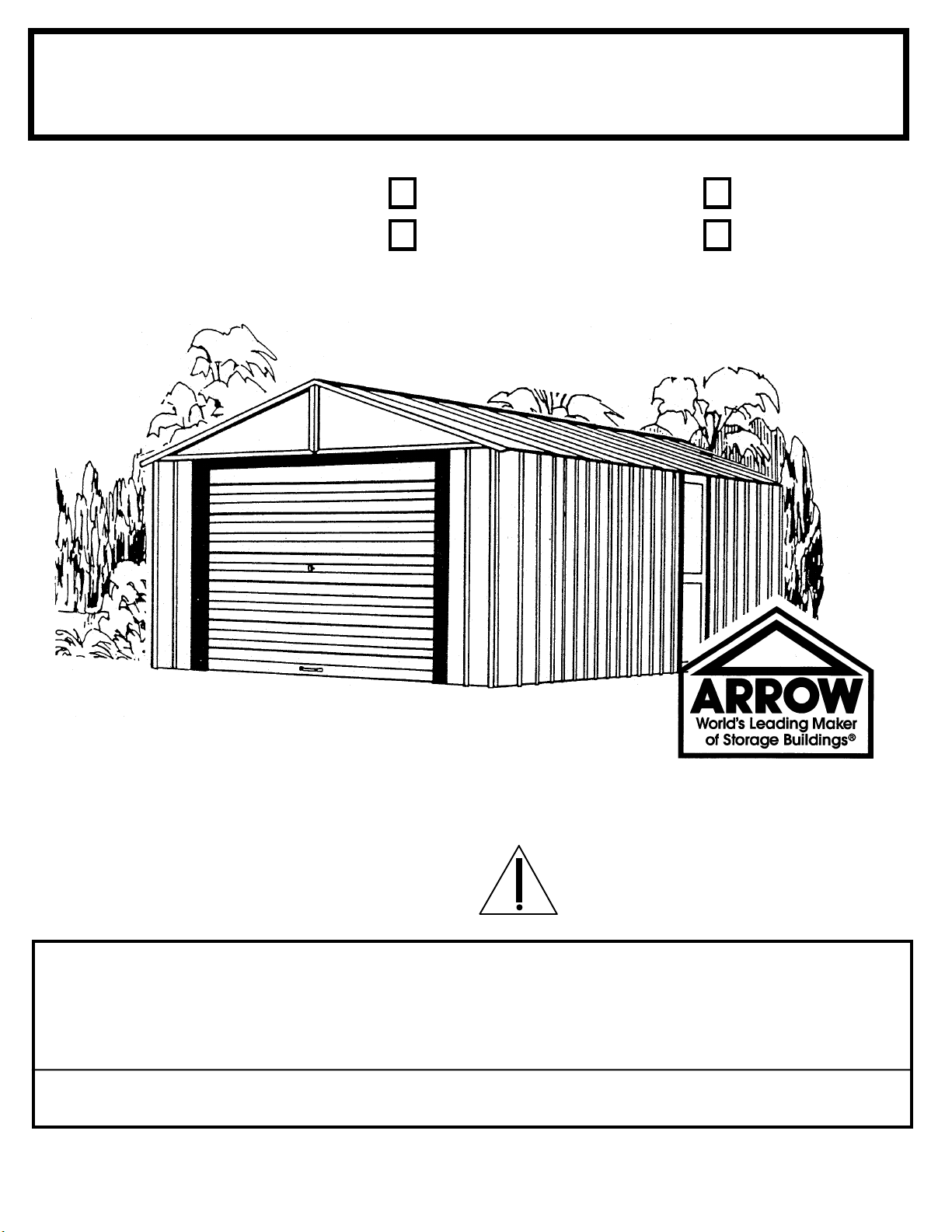
Owner's ManOwner's Man
Owner's Man
Owner's ManOwner's Man
BX1
ual & ual &
ual &
ual & ual &
AssembAssemb
Assemb
AssembAssemb
ll
y Instry Instr
l
y Instr
ll
y Instry Instr
uctionsuctions
uctions
uctionsuctions
Model No.Model No.
Model No.
Model No.Model No.
VT1421VT1421
VT1421
VT1421VT1421
VT1431VT1431
VT1431
VT1431VT1431
697.68889697.68889
697.68889
697.68889697.68889
697.68890697.68890
697.68890
697.68890697.68890
CAUTION: SOME PARTS HAVE SHARP EDGES. CARECAUTION: SOME PARTS HAVE SHARP EDGES. CARE
CAUTION: SOME PARTS HAVE SHARP EDGES. CARE
CAUTION: SOME PARTS HAVE SHARP EDGES. CARECAUTION: SOME PARTS HAVE SHARP EDGES. CARE
MUST BE TAKEN WHEN HANDLING THE VARIOUS PIECESMUST BE TAKEN WHEN HANDLING THE VARIOUS PIECES
MUST BE TAKEN WHEN HANDLING THE VARIOUS PIECES
MUST BE TAKEN WHEN HANDLING THE VARIOUS PIECESMUST BE TAKEN WHEN HANDLING THE VARIOUS PIECES
TO AVOID A MISHAP. FOR SAFETY SAKE, PLEASE READTO AVOID A MISHAP. FOR SAFETY SAKE, PLEASE READ
TO AVOID A MISHAP. FOR SAFETY SAKE, PLEASE READ
704910801
BUILDING DIMENSIONSBUILDING DIMENSIONS
BUILDING DIMENSIONS
BUILDING DIMENSIONSBUILDING DIMENSIONS
*Approx. Foundation Storage Area (Roof Edge to Roof Edge) (Wall to Wall) *Approx. Foundation Storage Area (Roof Edge to Roof Edge) (Wall to Wall)
*Approx. Foundation Storage Area (Roof Edge to Roof Edge) (Wall to Wall)
*Approx. Foundation Storage Area (Roof Edge to Roof Edge) (Wall to Wall) *Approx. Foundation Storage Area (Roof Edge to Roof Edge) (Wall to Wall)
Size Size Sq. Ft. Cu. Ft. Width Depth Height Width Depth Height Size Size Sq. Ft. Cu. Ft. Width Depth Height Width Depth Height
Size Size Sq. Ft. Cu. Ft. Width Depth Height Width Depth Height
Size Size Sq. Ft. Cu. Ft. Width Depth Height Width Depth Height Size Size Sq. Ft. Cu. Ft. Width Depth Height Width Depth Height
14' x 21' 164" x 255 1/2" 291 2527 169" 260 3/4" 116" 164" 255 1/2" 114 1/2"
14' x 31' 164" x 370 1/2" 422 3663 169" 375 3/4" 116" 164" 370 1/2" 114 1/2"
4,3m x 6,4m 4,17m x 6,49m 27,0m 71,6m 4,29m 6,62m 2,95m 4,17m 6,49m 2,91m
4,3m x 9,5m 4,17m x 9,41m 39,2m 103,7m 4,29m 9,54m 2,95m 4,17m 9,41m 2,91m
* Size rounded off to the nearest foot
Exterior Dimensions Interior Dimensions Exterior Dimensions Interior Dimensions
Exterior Dimensions Interior Dimensions
Exterior Dimensions Interior Dimensions Exterior Dimensions Interior Dimensions
23
23
TO AVOID A MISHAP. FOR SAFETY SAKE, PLEASE READTO AVOID A MISHAP. FOR SAFETY SAKE, PLEASE READ
SAFETY INFORMATION PROVIDED IN THIS MANUALSAFETY INFORMATION PROVIDED IN THIS MANUAL
SAFETY INFORMATION PROVIDED IN THIS MANUAL
SAFETY INFORMATION PROVIDED IN THIS MANUALSAFETY INFORMATION PROVIDED IN THIS MANUAL
BEFORE BEGINNING CONSTRUCTION. WEAR GLOVESBEFORE BEGINNING CONSTRUCTION. WEAR GLOVES
BEFORE BEGINNING CONSTRUCTION. WEAR GLOVES
BEFORE BEGINNING CONSTRUCTION. WEAR GLOVESBEFORE BEGINNING CONSTRUCTION. WEAR GLOVES
WHEN HANDLING METAL PARTS.WHEN HANDLING METAL PARTS.
WHEN HANDLING METAL PARTS.
WHEN HANDLING METAL PARTS.WHEN HANDLING METAL PARTS.
Page 2

BEFORE BEFORE
BEFORE
BEFORE BEFORE
A2
Owner's ManualOwner's Manual
Owner's Manual
Owner's ManualOwner's Manual
Before beginning construction, check local building codes regarding footings, location
and other requirements. Study and understand this owner's manual.
Important information and helpful tips will make your construction easier and more
enjoyable.
Assembly Instructions:Assembly Instructions:
Assembly Instructions: Instructions are supplied in this manual and contain all
Assembly Instructions:Assembly Instructions:
appropriate information for your building model. Review all instructions before you begin,
and during assembly, follow the step sequence carefully for correct results.
FF
oundaounda
F
ounda
FF
oundaounda
tion and tion and
tion and
tion and tion and
AncAnc
Anc
AncAnc
horhor
ing:ing:
hor
ing: Your storage building must be anchored to pre vent wind
horhor
ing:ing:
YY
OU BEGINOU BEGIN
Y
OU BEGIN
YY
OU BEGINOU BEGIN
........
....
........
damage. A foundation is also necessary as a base in order to construct a square and level
building. Anchoring and foundation materials are not included with your building. We
recommend the combined use of an
AncAnc
horing Kithoring Kit
Anc
horing Kit as an effective method of securing your building to the ground (Available
AncAnc
horing Kithoring Kit
by mail order or at your local dealer) or you may construct the foundation and anchoring
system of your choice. Your assembly instructions provide information on a few methods
commonly used to secure and level a storage building.
PP
arar
ts and Pts and P
P
ar
ts and P
PP
arar
ts and Pts and P
building.
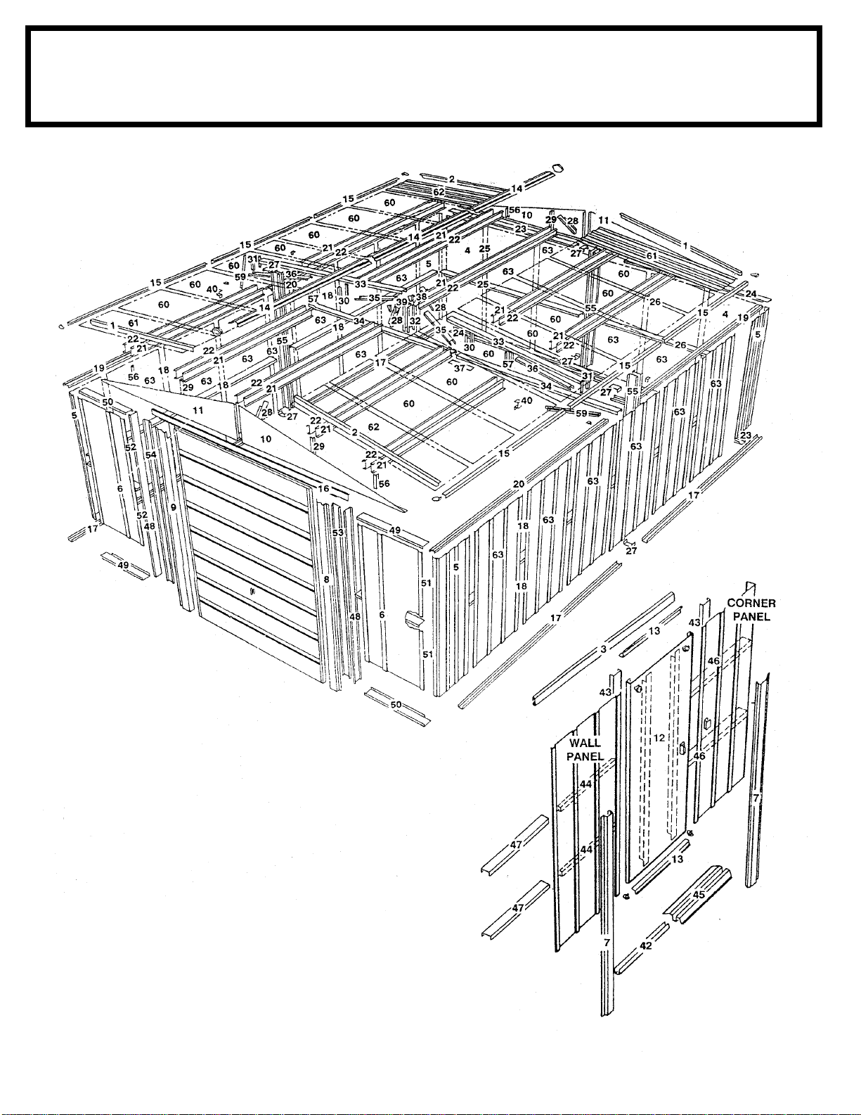
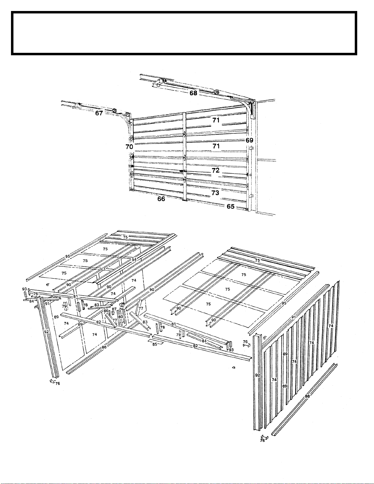
•All part numbers can be found on the parts. All of these numbers (before the -) must agree with the
numbers on the parts list. The parts list is located on page 12.
•If you find that a part is missing, include the model number of your building and contact:
Arrow Group Industries, Inc. Customer Service DepartmentArrow Group Industries, Inc. Customer Service Department
Arrow Group Industries, Inc. Customer Service Department
Arrow Group Industries, Inc. Customer Service DepartmentArrow Group Industries, Inc. Customer Service Department
Route 50 East Breese, Illinois 62230Route 50 East Breese, Illinois 62230
Route 50 East Breese, Illinois 62230
Route 50 East Breese, Illinois 62230Route 50 East Breese, Illinois 62230
arar
ts List:ts List:
ar
ts List: Check to be sure that y ou have all the necessary parts for your
arar
ts List:ts List:
Arrow Floor Foundation Kit Arrow Floor Foundation Kit
Arrow Floor Foundation Kit and an
Arrow Floor Foundation Kit Arrow Floor Foundation Kit
Arrow Arrow
Arrow
Arrow Arrow
1-800-851-10851-800-851-1085
1-800-851-1085
1-800-851-10851-800-851-1085
•Separate contents of the carton by the part number while reviewing parts list. The first few steps
show how to join related parts to make larger sub assemblies which will be used later.
•Familiarize yourself with the hardware and fasteners for easier use during construction. These are
packaged within the carton. Note that extra fasteners have been supplied for your convenience.
2
Page 3
PLAN PLAN
PLAN
PLAN PLAN
A3
WW
aa
tctc
W
WW
Do not attempt to assemble your building on a windy day. Be careful on wet or muddy
ground.
TT
T
TT
your building. One person can position parts or panels while the other is able to handle
the fasteners and the tools.
TT
T
TT
construction of your building. Decide which method of anchoring and the type of
foundation you wish to use in order to form a complete list of the materials you will need.
h the h the
a
tc
h the
aa
tctc
h the h the
eamweamw
eamw
eamweamw
ools and Maools and Ma
ools and Ma
ools and Maools and Ma
oror
or
oror
WW
eaea
ther:ther:
ea
ther:
eaea
ther:ther:
Whenever possible, two or more people should work together to assemble
terter
ter
terter
k:k:
k:
k:k:
W
WW
Be sure the day you select to install y our building is dry and calm.
ials:ials:
ials:
ials:ials:
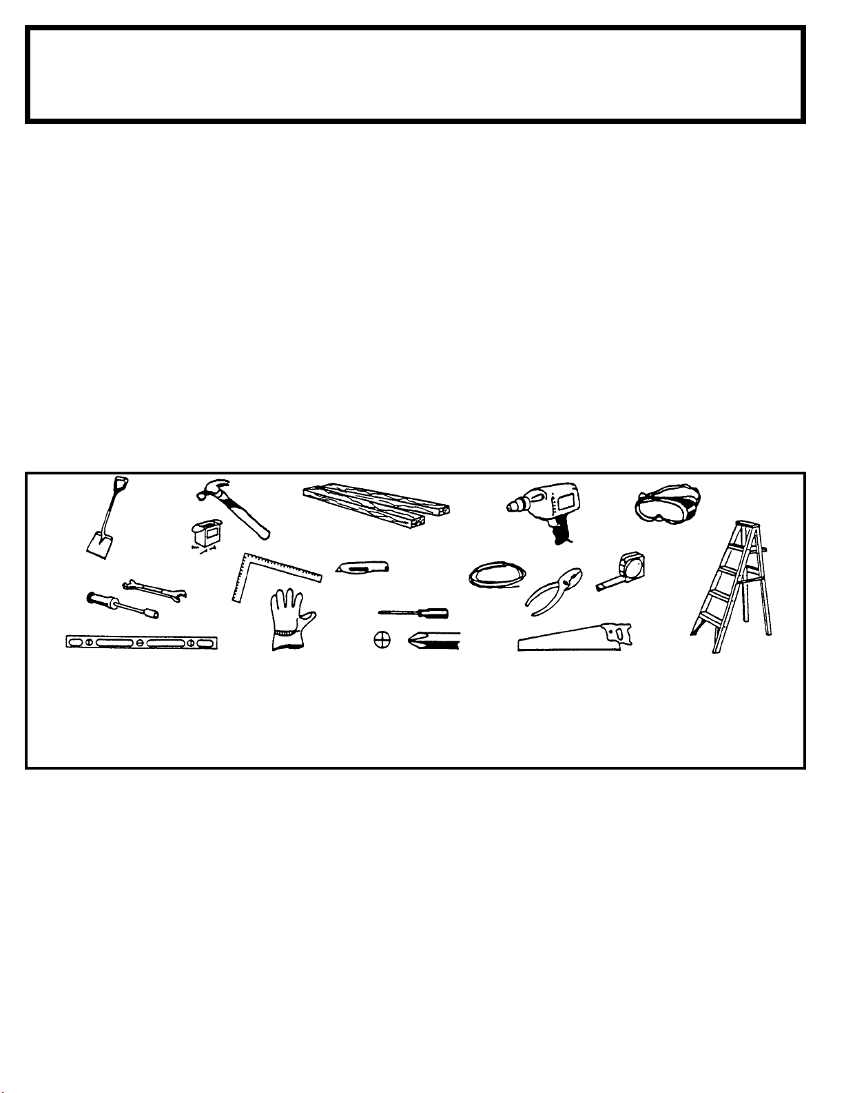
These are some basic tools and materials you will need for the
AHEADAHEAD
AHEAD
AHEADAHEAD
........
....
........
Required
• Eye Goggles
• No. 2 Phillips Screwdriver
(With Hardened Magnetic Tip)
Note: A power screwdriver or variable speed drill with Phillips-tip attachment can speed assembly by
as much as 40%.
Selecting and PrSelecting and Pr
Selecting and Pr
Selecting and PrSelecting and Pr
a location for your building. The best location is a level area with good drainage.
•Allow enough working space for ease of moving parts into position during assembly. Be sure there
will be enough space at entrance for doors to open fully and enough space around the building to
be able to fasten the panel screws from the outside.
•Before you begin the first steps in assembling your parts, a foundation should be constructed and
an anchoring system should be ready to use.
• Work Gloves
• Step Ladder
• Utility Knife / Scissors
• Pliers
• Carpenter's Level
• Tape Measure
ee
parpar
e
par
ee
parpar
Required
ing ing
ing
ing ing
YY
our Site:our Site:
Y
our Site:
YY
our Site:our Site:
Optional Time-Savers
• Wrench / Nut Driver
• Electric / Cordless Drill
• Square
• String (for squaring frame)
Before assembly, you will want to decide on
Foundation Preparation
• Hammer and Nails
• Spade or Shovel
• Hand Saw / Power Saw
• Lumber and/or Concrete
3
Page 4
SAFETY FIRSTSAFETY FIRST
SAFETY FIRST
SAFETY FIRSTSAFETY FIRST
A4
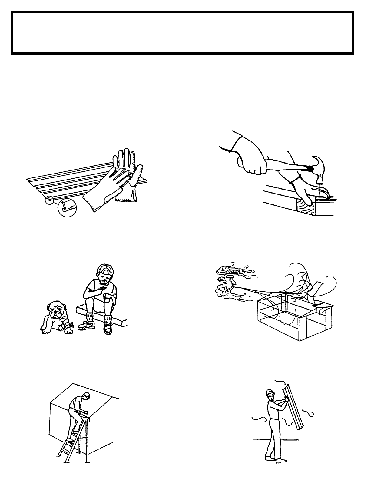
Safety precautions are important to follow throughout the construction of your building.Safety precautions are important to follow throughout the construction of your building.
Safety precautions are important to follow throughout the construction of your building.
Safety precautions are important to follow throughout the construction of your building.Safety precautions are important to follow throughout the construction of your building.
........
....
........
•Care must be taken when handling various
pieces of your building since some contain
sharp edges. Please wear work gloves, eye
protection and long sleeves when assembling
or performing any maintenance on your building.
safety edge
sharp edge
sharp edge
safety edge
•Keep children and pets away from worksite to
avoid distractions and any accidents which
may occur.
•Practice caution with the tools being used in the
assembly of this building. Be familiar with the
operation of all power tools.
•Do not attempt to assemble the building if parts
are missing because any building left partially
assembled may be seriously damaged by light
winds. Call 1-800-851-1085
•Never concentrate your total weight on the
roof of the building. When using a step ladder
make sure that it is fully open and on even
ground before climbing on it.
4
•Do not attempt to assemble the building on a
windy day, because the large panels acting as a
"sail", can be whipped about by the wind making
construction difficult and unsafe.
Page 5
CARE & MAINTENCARE & MAINTEN
CARE & MAINTEN
CARE & MAINTENCARE & MAINTEN
A5 Web
FF
inish:inish:
F
inish: For long lasting finish, periodically clean and wax the exterior surface. Touch-
FF
inish:inish:
up scratches as soon as you notice them on your unit. Immediately clean the area with
a wire brush; wash it and apply touch-up paint per manufacturer's recommendation.
ANCE....ANCE....
ANCE....
ANCE....ANCE....
Roof:Roof:
Roof:
Roof:Roof:
amounts of snow on roof can damage building making it unsafe to enter. In snow country,
Roof Strengthening Kits are available for most Arrow Buildings for added protection
against heavy snow accumulation.
DoorDoor
Door
DoorDoor
sliding easily. Lubricate door track annually with furniture polish or silicone spray. Keep
doors closed and locked to prevent wind damage.
FF
astenerastener
F
astener
FF
astenerastener
the metal from being scratched by scre ws. Regularly check your building f or loose scre ws ,
bolts, nuts, etc. and retighten them as necessary.
Moisture: Moisture:
Moisture: A plastic sheet (vapor barrier) placed under the entire floor area with good
Moisture: Moisture:
ventilation will reduce condensation.
Other Other
Other
Other Other
Keep roof clear of leaves and snow with long handled, soft-bristled broom. Heavy
s:s:
s:
Always keep the door trac ks clear of dirt and other debris that prevent them from
s:s:
s:s:
s:
Use all washers supplied to protect against weather infiltration and to protect
s:s:
TT
ips....ips....
T
ips....
TT
ips....ips....
• Wash off inked part numbers on coated panels with soap and water.
• Silicone caulking may be used for watertight seals throughout the building.
Do not store swimming pool chemicals in your building. Combustibles andDo not store swimming pool chemicals in your building. Combustibles and
Do not store swimming pool chemicals in your building. Combustibles and
Do not store swimming pool chemicals in your building. Combustibles andDo not store swimming pool chemicals in your building. Combustibles and
corrosives must be stored in air tight approved containers.corrosives must be stored in air tight approved containers.
corrosives must be stored in air tight approved containers.
corrosives must be stored in air tight approved containers.corrosives must be stored in air tight approved containers.
Keep this Owner's Manual and Assembly Instructions for future reference.Keep this Owner's Manual and Assembly Instructions for future reference.
Keep this Owner's Manual and Assembly Instructions for future reference.
Keep this Owner's Manual and Assembly Instructions for future reference.Keep this Owner's Manual and Assembly Instructions for future reference.
5
Page 6
AA
CCESSORIESCCESSORIES
A
CCESSORIES
AA
CCESSORIESCCESSORIES
A6 WEB
RR
OOF STRENGTHENING (heaOOF STRENGTHENING (hea
R
OOF STRENGTHENING (hea
RR
OOF STRENGTHENING (heaOOF STRENGTHENING (hea
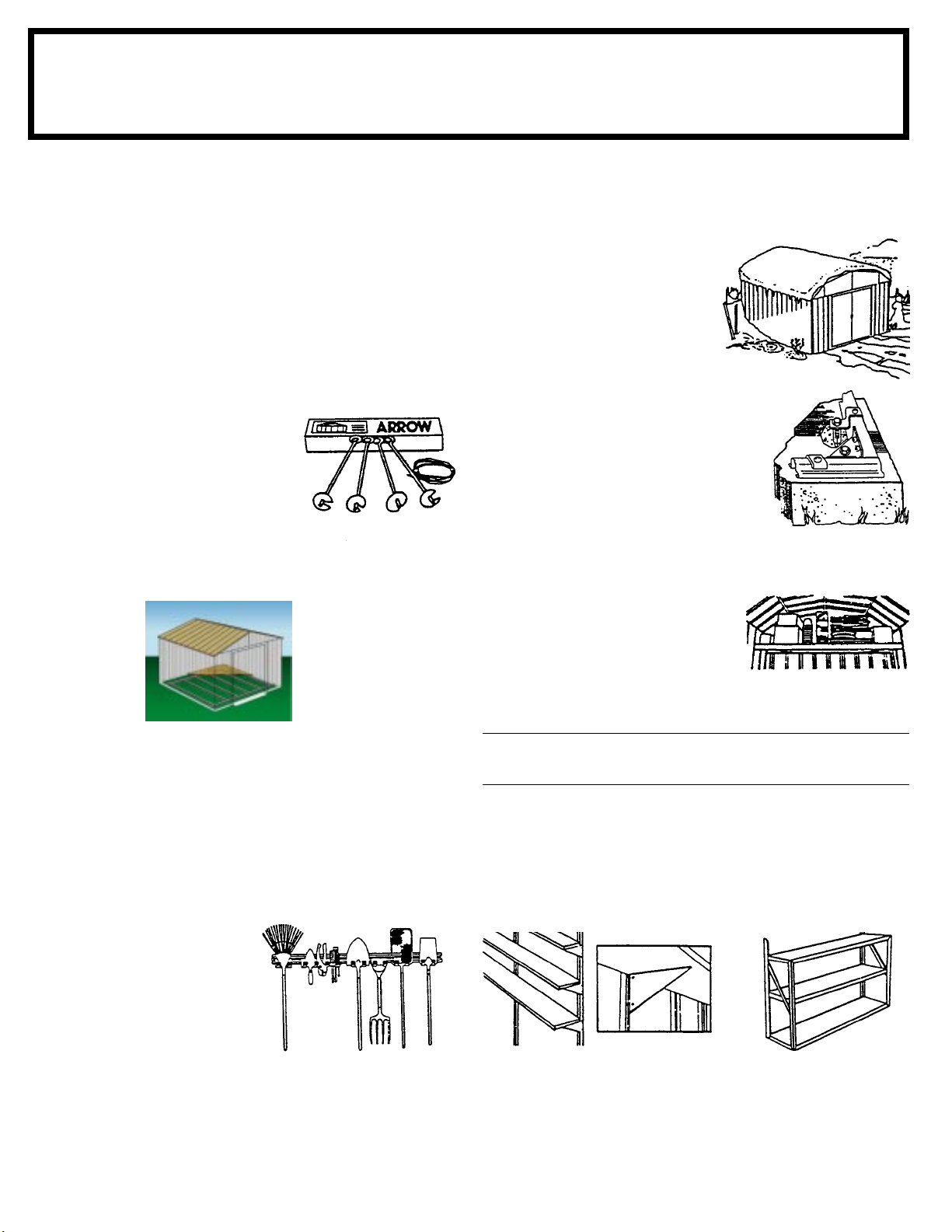
designed for added protection against heavy snow accumulation. Increases the strength of your roof by 50%.
ANCHOR KITANCHOR KIT
ANCHOR KIT
ANCHOR KITANCHOR KIT
Model No. AK4Model No. AK4
Model No. AK4
Model No. AK4Model No. AK4
Anchor Kit contains heavy-duty steel
augers, 60' (18m) of steel cable and 4 cable
clamps. No digging or concrete
pouring, just insert cable under roof,
over roof beams, into augers and twist
augers into the ground. For buildings
larger than 10'x9', use 2 kits.
vy snovy sno
vy sno
vy snovy sno
w load) KITSw load) KITS
w load) KITS Extra roof beams and gable braces
w load) KITSw load) KITS
ANCHOR KITANCHOR KIT
ANCHOR KIT
ANCHOR KITANCHOR KIT
Model No. AK100Model No. AK100
Model No. AK100
Model No. AK100Model No. AK100
New concrete anchor system permits
anchoring any size Arrow building
directly to a concrete slab. Each kit
contains heavy-duty, hot-dipped
galvanized steel corner gussets and
perimeter clips which fit over the floor
frame and lag bolt into a concrete slab.
Full assembly instructions and a 1/4"
masonary drill bit are included.
........
....
........
FLOOR FOUNDFLOOR FOUND
FLOOR FOUND
FLOOR FOUNDFLOOR FOUND
MODELS FB47410, FB5465, FB106-A
FB109-A, FB1010 AND FB1014-A
A simple new floor frame system made of heavy-duty, hot-dipped
galvanized steel. Use as foundation for plywood, sand or stone.
TT
OOL HANGING RAOOL HANGING RA
T
OOL HANGING RA
TT
OOL HANGING RAOOL HANGING RA
Model No. TH100Model No. TH100
Model No. TH100
Model No. TH100Model No. TH100
The perfect tool organizer. Twin
25 1/2" (65cm) steel channels
plus five heavy-duty snap-in
hangers and a small tool holder for
screwdrivers, pliers, etc. Holders
slide along channel for fully
adjustable spacing. Great for
garage, basement, or the back
of any door. Fits all Arrow
storage buildings.
6
AA
TION KITSTION KITS
A
TION KITS
AA
TION KITSTION KITS
CKCK
CK
CKCK
AA
TTIC KIT / TTIC KIT /
A
TTIC KIT /
AA
TTIC KIT / TTIC KIT /
Heavy-duty galvanized steel bars that
fit all 10' wide Arrow buildings. They
install quickly and easily to help
organize space and create more
useable space as an attic or
workbench. Will hold up to 250 lbs.
(113kg) evenly distributed.
Model No.Model No.
Model No.
Model No.Model No.
Must be drilled for use as workbench in Estator.
+ Even weight distribution.
SHELF UNITSSHELF UNITS
SHELF UNITS
SHELF UNITSSHELF UNITS
Heavy-duty, galvanized steel shelf units help organize storage
space. They easily mount on the wall or sit on the floor. Fits all
Arrow buildings.*
Model No. SS404
• Makes 8" to 12" (20-30cm)
wide shelves in any length.
• Brackets, braces,
hardware included.
Lumber is not included.
* Some drilling required to fit buildings without mid-wall bracing.
WW
ORKBENCH KITORKBENCH KIT
W
ORKBENCH KIT
WW
ORKBENCH KITORKBENCH KIT
FitsFits
Fits
FitsFits
10' Long, 250 lb. (113kg) load+
Fits all Arrow 10' wide buildings.
Model No. SS900-A
• Grey color
• 3 shelves
• Holds up to 85 lbs. (38kg)
(even weight distribution)
Shipping WeightShipping Weight
Shipping Weight
Shipping WeightShipping Weight
16 lbs. (7kg)AT101
Page 7

THIS
PAGE
WAS
LEFT
BLANK
INTENTIONALLY
7
Page 8

THIS
PAGE
WAS
LEFT
BLANK
INTENTIONALLY
8
Page 9
FF
oundaounda
F
ounda
FF
oundaounda
BX9
TT
he Fhe F
T
he F
TT
he Fhe F
Concrete SlabConcrete Slab
Concrete Slab
Concrete SlabConcrete Slab
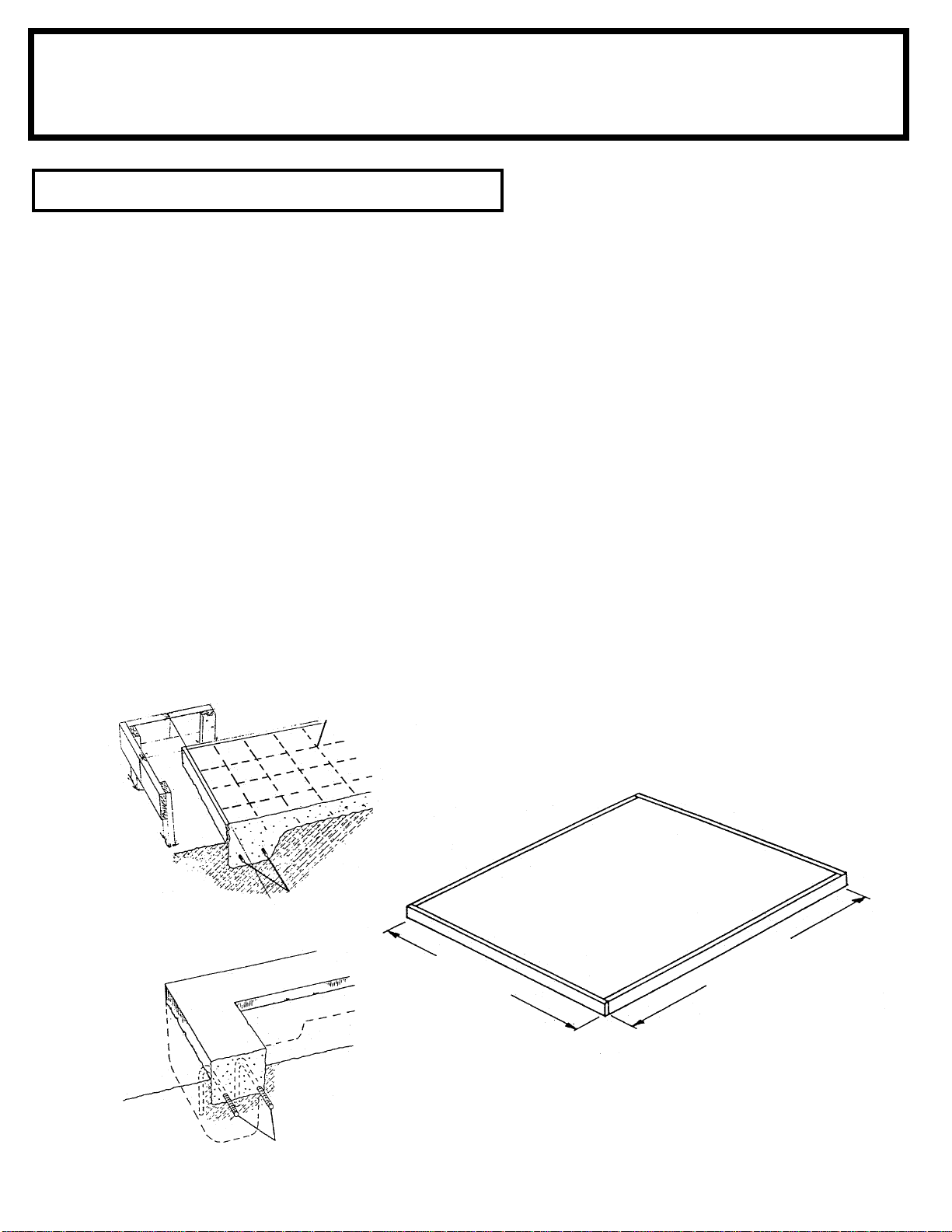
The slab should be at least 3" to 4" (8-10cm) thick. It must be level and flat to provide good support for the frame.The slab should be at least 3" to 4" (8-10cm) thick. It must be level and flat to provide good support for the frame.
The slab should be at least 3" to 4" (8-10cm) thick. It must be level and flat to provide good support for the frame.
The slab should be at least 3" to 4" (8-10cm) thick. It must be level and flat to provide good support for the frame.The slab should be at least 3" to 4" (8-10cm) thick. It must be level and flat to provide good support for the frame.
The following are the recommended materials for your foundation.The following are the recommended materials for your foundation.
The following are the recommended materials for your foundation.
The following are the recommended materials for your foundation.The following are the recommended materials for your foundation.
● 2 x 4's (5cm x 10cm) (will be removed once the concrete cures)
● Concrete ● Sheet of 6 mil plastic
● We recommend for a proper strength concrete to use a mix of:
1 part cement ● 3 parts pea sized gravel ● 2 1/2 parts clean sand
Prepare the Site/Construct a FoundationPrepare the Site/Construct a Foundation
Prepare the Site/Construct a Foundation
Prepare the Site/Construct a FoundationPrepare the Site/Construct a Foundation
1. Dig a square, 6" (15cm) deep into the ground (remove grass).
2. Fill up to 4" (10cm) in the square with gravel and tamp firm.
3. Cover gravel with a sheet of 6 mil plastic.
4. Construct a wood frame using four planks of 2x4 (5cm x 10cm)
lumber.
5. Pour in concrete to fill in the hole and the frame giving a
total of 4" (8-10cm) thick concrete. Be sure surface is level.
oundaounda
ounda
oundaounda
tion Ftion F
tion F
tion Ftion F
or or
or
or or
YY
our Buildingour Building
Y
our Building
YY
our Buildingour Building
tiontion
tion
tiontion
Allow 3 - 5 hours for construction and a week for concrete curing time.Allow 3 - 5 hours for construction and a week for concrete curing time.
Allow 3 - 5 hours for construction and a week for concrete curing time.
Allow 3 - 5 hours for construction and a week for concrete curing time.Allow 3 - 5 hours for construction and a week for concrete curing time.
Note: Before beginning construction, check local building codesNote: Before beginning construction, check local building codes
Note: Before beginning construction, check local building codes
Note: Before beginning construction, check local building codesNote: Before beginning construction, check local building codes
regarding footings, location and other requirements.regarding footings, location and other requirements.
regarding footings, location and other requirements.
regarding footings, location and other requirements.regarding footings, location and other requirements.
Welded Wire
Fabric
Reinforcing
Rods
Optional Footer Type of FoundationOptional Footer Type of Foundation
Optional Footer Type of Foundation
Optional Footer Type of FoundationOptional Footer Type of Foundation
FRONT (ROLL-UP DOOR)FRONT (ROLL-UP DOOR)
FRONT (ROLL-UP DOOR)
FRONT (ROLL-UP DOOR)FRONT (ROLL-UP DOOR)
164"164"
164"
164"164"
4,17m4,17m
4,17m
4,17m4,17m
21' - 255 1/2"21' - 255 1/2"
21' - 255 1/2"
21' - 255 1/2"21' - 255 1/2"
31' - 370 1/2"31' - 370 1/2"
31' - 370 1/2"
31' - 370 1/2"31' - 370 1/2"
6,49m6,49m
6,49m
6,49m6,49m
9,41m9,41m
9,41m
9,41m9,41m
Reinforcing
Rods
Note: Note:
Note: Finished Slab dimensions, with lumber removed.
Note: Note:
9
Page 10
AnchoringAnchoring
Anchoring
AnchoringAnchoring
A10
AncAnc
Anc
AncAnc
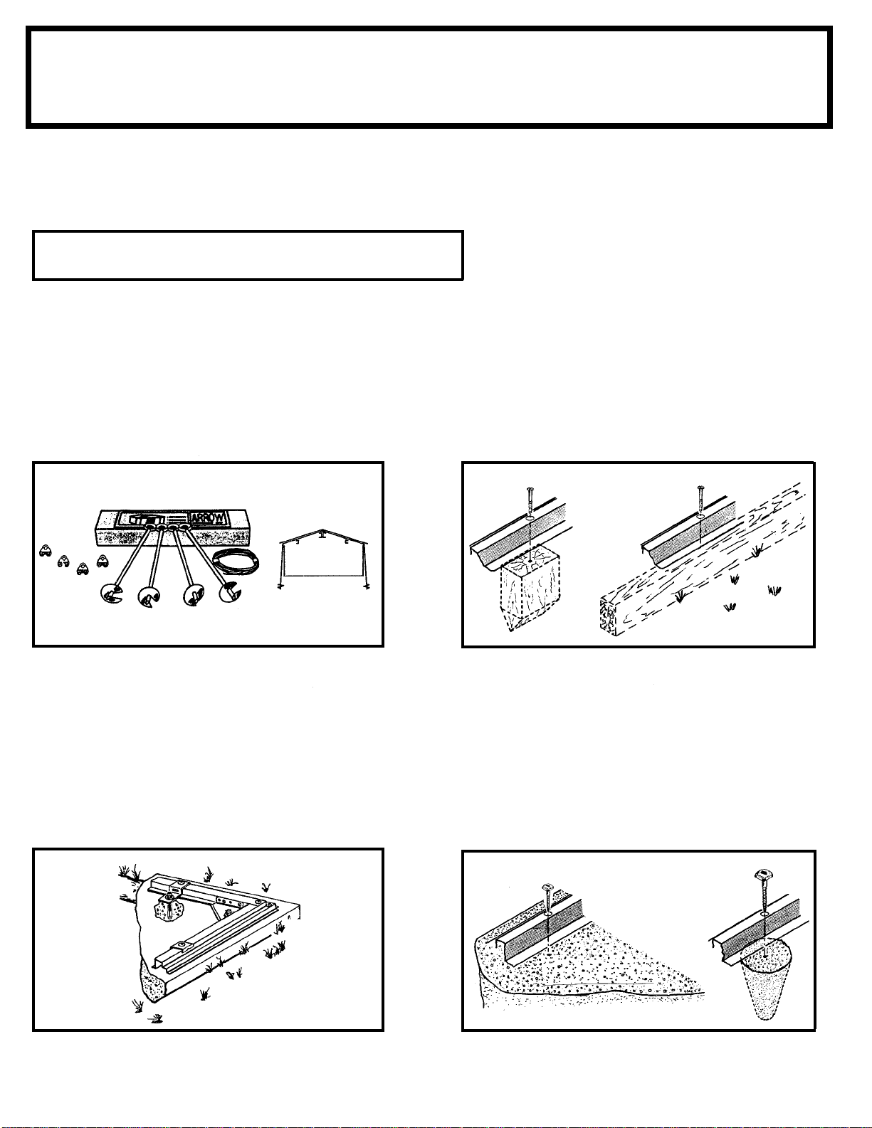
It is important that the entire floor frame be anchored after the building is erected.It is important that the entire floor frame be anchored after the building is erected.
It is important that the entire floor frame be anchored after the building is erected.
It is important that the entire floor frame be anchored after the building is erected.It is important that the entire floor frame be anchored after the building is erected.
Below are recommended ways of anchoring.
Arrow Anchoring Kit:Arrow Anchoring Kit:
Arrow Anchoring Kit:
Arrow Anchoring Kit:Arrow Anchoring Kit:
Recommended for use with
Contains: Contains:
Contains: 4 Anchors with Cable, Clamps and
Contains: Contains:
installation instruction.
horhor
hor
horhor
ing Doing Do
ing Do
ing Doing Do
wn wn
TT
wn
T
wn wn
TT
(Model No. AK4 or 60298)
any any
any suggested
any any
he Buildinghe Building
he Building
he Buildinghe Building
base.base.
base.
base.base.
Anchoring into Wood/Post:Anchoring into Wood/Post:
Anchoring into Wood/Post:
Anchoring into Wood/Post:Anchoring into Wood/Post:
Use 1/4" Wood Screws. There are 1/4" (0,63cm) dia.
holes provided in the frames for proper anchoring.
1. 2.
OVER THE BEAMS
AND INTO THE GROUND
Arrow Anchoring Kit:Arrow Anchoring Kit:
Arrow Anchoring Kit:
Arrow Anchoring Kit:Arrow Anchoring Kit:
Recommended for use with the
Contains: Contains:
Contains: Corner gussets, perimeter clips, hardware,
Contains: Contains:
1/4" masonary drill bit and installation instruction.
(Model No. AK100 or 68383)
concrete concrete
concrete foundation.
concrete concrete
Anchoring into Concrete:Anchoring into Concrete:
Anchoring into Concrete:
Anchoring into Concrete:Anchoring into Concrete:
1. For poured concrete slab or footing or patio blocks:
Use 1/4" x 2" Lag Screws.
2. For Anchor Post of Concrete poured after building is
erected: Use 1/4" x 6" Lag Screws.
1.
2.
10
Page 11
BX11
KIT 1KIT 1
KIT 1
KIT 1KIT 1
6510165101
65101
6510165101
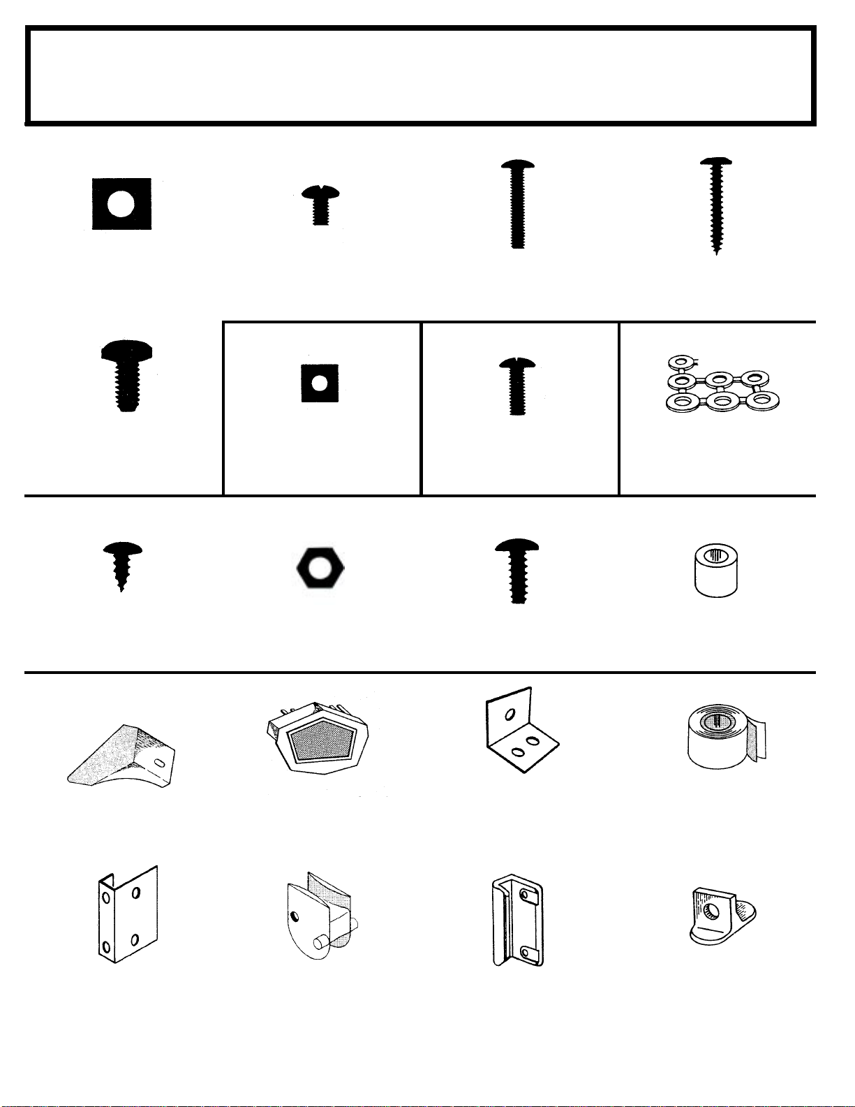
1/4-20 Square Nut1/4-20 Square Nut
1/4-20 Square Nut
1/4-20 Square Nut1/4-20 Square Nut
132 (14x21)132 (14x21)
132 (14x21)
132 (14x21)132 (14x21)
254 (14x31)254 (14x31)
254 (14x31)
254 (14x31)254 (14x31)
HarHar
Har
HarHar
dd
d
dd
#10-32x1/4" Bolts (3)#10-32x1/4" Bolts (3)
#10-32x1/4" Bolts (3)
#10-32x1/4" Bolts (3)#10-32x1/4" Bolts (3)
ww
w
ww
6540865408
65408
6540865408
arar
ar
arar
e fe f
e f
e fe f
or Buildingor Building
or Building
or Buildingor Building
6595865958
65958
6595865958
#8-32x7/8" Bolt (2)#8-32x7/8" Bolt (2)
#8-32x7/8" Bolt (2)
#8-32x7/8" Bolt (2)#8-32x7/8" Bolt (2)
6591465914
65914
6591465914
#6Ax7/8"Screw (4)#6Ax7/8"Screw (4)
#6Ax7/8"Screw (4)
#6Ax7/8"Screw (4)#6Ax7/8"Screw (4)
6598965989
65989
6598965989
1/4-20x1/2" Hex Head Bolt1/4-20x1/2" Hex Head Bolt
1/4-20x1/2" Hex Head Bolt
1/4-20x1/2" Hex Head Bolt1/4-20x1/2" Hex Head Bolt
132 (14x21)132 (14x21)
132 (14x21)
132 (14x21)132 (14x21)
254 (14x31)254 (14x31)
254 (14x31)
254 (14x31)254 (14x31)
HARDWARE SUB KITHARDWARE SUB KIT
HARDWARE SUB KIT
HARDWARE SUB KITHARDWARE SUB KIT
6500465004
65004
6500465004
#8Ax5/16" Screw#8Ax5/16" Screw
#8Ax5/16" Screw
#8Ax5/16" Screw#8Ax5/16" Screw
813 (14x21)813 (14x21)
813 (14x21)
813 (14x21)813 (14x21)
1092 (14x31)1092 (14x31)
1092 (14x31)
1092 (14x31)1092 (14x31)
REMAINING HARDWARE PIECESREMAINING HARDWARE PIECES
REMAINING HARDWARE PIECES
REMAINING HARDWARE PIECESREMAINING HARDWARE PIECES
#10-32 Square Nut#10-32 Square Nut
#10-32 Square Nut
#10-32 Square Nut#10-32 Square Nut
501 (14x21)501 (14x21)
501 (14x21)
501 (14x21)501 (14x21)
673 (14x31)673 (14x31)
673 (14x31)
673 (14x31)673 (14x31)
#8-32 Hex Nut (2)#8-32 Hex Nut (2)
#8-32 Hex Nut (2)
#8-32 Hex Nut (2)#8-32 Hex Nut (2)
KIT 2KIT 2
KIT 2
KIT 2KIT 2
6510665106
65106
6510665106
6510365103
65103
6510365103
KIT 3KIT 3
KIT 3
KIT 3KIT 3
6594365943
65943
6594365943
#10-32x7/16" Bolt#10-32x7/16" Bolt
#10-32x7/16" Bolt
#10-32x7/16" Bolt#10-32x7/16" Bolt
498 (14x21)498 (14x21)
498 (14x21)
498 (14x21)498 (14x21)
670 (14x31)670 (14x31)
670 (14x31)
670 (14x31)670 (14x31)
Remove from bag and saveRemove from bag and save
Remove from bag and save
Remove from bag and saveRemove from bag and save
for Step 24for Step 24
for Step 24
for Step 24for Step 24
65900A65900A
65900A
65900A65900A
#10Bx1/2" Black Screw (2)#10Bx1/2" Black Screw (2)
#10Bx1/2" Black Screw (2)
#10Bx1/2" Black Screw (2)#10Bx1/2" Black Screw (2)
WASHER KITWASHER KIT
WASHER KIT
WASHER KITWASHER KIT
6664666646
66646
6664666646
WasherWasher
Washer
WasherWasher
960 (14x21)960 (14x21)
960 (14x21)
960 (14x21)960 (14x21)
1400 (14x31)1400 (14x31)
1400 (14x31)
1400 (14x31)1400 (14x31)
6609866098
66098
6609866098
Plastic Spacer (6)Plastic Spacer (6)
Plastic Spacer (6)
Plastic Spacer (6)Plastic Spacer (6)
6644466444
66444
6644466444
Roof Trim CapRoof Trim Cap
Roof Trim Cap
Roof Trim CapRoof Trim Cap
(2 right & 2 left)(2 right & 2 left)
(2 right & 2 left)
(2 right & 2 left)(2 right & 2 left)
79727972
7972
79727972
Door Handle Lock Bracket (1)Door Handle Lock Bracket (1)
Door Handle Lock Bracket (1)
Door Handle Lock Bracket (1)Door Handle Lock Bracket (1)
66446 (Arrow Logo)66446 (Arrow Logo)
66446 (Arrow Logo)
66446 (Arrow Logo)66446 (Arrow Logo)
Peak Cap (2)Peak Cap (2)
Peak Cap (2)
Peak Cap (2)Peak Cap (2)
6624266242
66242
6624266242
Door Slide (2)Door Slide (2)
Door Slide (2)
Door Slide (2)Door Slide (2)
70227022
7022
70227022
Eave BracketEave Bracket
Eave Bracket
Eave BracketEave Bracket
4 (14x21)4 (14x21)
4 (14x21)
4 (14x21)4 (14x21)
8 (14x31)8 (14x31)
8 (14x31)
8 (14x31)8 (14x31)
6626066260
66260
6626066260
Handle (2)Handle (2)
Handle (2)
Handle (2)Handle (2)
Weather StrippingWeather Stripping
Weather Stripping
Weather StrippingWeather Stripping
67293 (1)67293 (1)
67293 (1)
67293 (1)67293 (1)
67545 (1 14x21) (2 14x31)67545 (1 14x21) (2 14x31)
67545 (1 14x21) (2 14x31)
67545 (1 14x21) (2 14x31)67545 (1 14x21) (2 14x31)
6638266382
66382
6638266382
Lower Door Guide (2)Lower Door Guide (2)
Lower Door Guide (2)
Lower Door Guide (2)Lower Door Guide (2)
11
Page 12
Parts ListParts List
Parts List
BX12
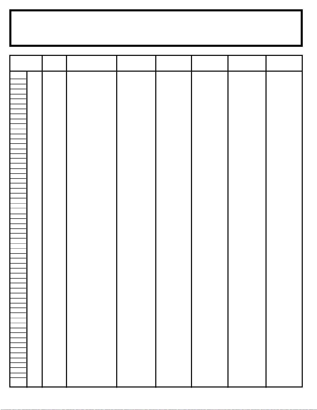
Carton #1 through #5 contains the VT1421. Carton 6 on Page 14 contains the Roll-up-Door for this building and parts for VT1431.
Assembly Part Part
Key No. Number Description Carton 1 Carton 2 Carton 3 Carton 4 Carton 5
1 7023 Left Roof Trim 2
2 7024 Right Roof Trim 2
3 7562 Track 1
4 9471 Wall Panel 2
5 9472 Corner Panel 4
6 9473 Front Wall Panel 2
7 9477 Door Jamb 2
8 9488 Right Door Jamb 1
9 9489 Left Door Jamb 1
10 9494 Right Gable 2
11 9495 Left Gable 2
12 9498 Door 1
13 9499 Horizontal Door Brace 2
14 9509 Ridge Cap 3
15 9510 Side Roof Trim 6
16 9474 Lintel 1
17 9475 Side Floor Frame 4
18 9476 Side Wall Channel 6
19 9484 Right Side Eave Channel 2
20 9485 Left Side Eave Channel 2
21 9502 Right Roof Beam 10
22 9503 Left Roof Beam 10
23 6938 Rear Frame 2
24 6939 Rear Frame 2
25 6942 Right Rear Wall Channel 2
26 6943 Left Rear Wall Channel 2
27 6947 Column Gusset 6
28 6954 Gable/Truss Strut 4
29 6955 Inner Gable Bracket 4
30 6958 Inner Truss Bracket 4
31 6959 Outer Truss Bracket 4
32 6962 Vertical Brace 2
33 6963 Upper Chord 2
34 6964 Lower Chord 2
35 6965 Inner Diagonal Brace 2
36 6966 Outer Diagonal Brace 2
37 6967 Splice Plate 1
38 7003 Left Shear Plate 2
39 7004 Right Shear Plate 2
40 7817 Spring Support Bracket 2
42 9464 Lower Door Track 1
43 9465 Support Column 2
44 9466 Wall Channel 2
45 9467 Ramp 1
46 9468 Corner Door Channel 2
47 9469 Side Door Channel 2
48 9478 Front Column 2
49 9480 Front Frame 2
50 9481 Front Frame 2
51 9482 Right Front Wall Channel 2
52 9483 Left Front Wall Channel 2
53 9486 Right Track Support 1
54 9487 Left Track Support 1
55 9490 Center Column 6
56 9496 Outer Gable Bracket 4
57 9497 Outer Truss Bracket 4
58 9500 Vertical Door Brace 2
59 9511 Track Strut 2
60 9491 Roof Panel 14
61 9492 Right Roof Panel 2
62 9493 Left Roof Panel 2
63 9470 Wall panel 17
Parts ListParts List
12
Page 13
AssembAssemb
Assemb
AssembAssemb
BX13
ll
y by b
l
y b
ll
y by b
y Ky K
y K
y Ky K
ee
y No. fy No. f
e
y No. f
ee
y No. fy No. f
or 14x21 Buildingor 14x21 Building
or 14x21 Building
or 14x21 Buildingor 14x21 Building
13
Page 14
BX14
PP
P
PP
arar
ts List fts List f
ar
ts List f
arar
ts List fts List f
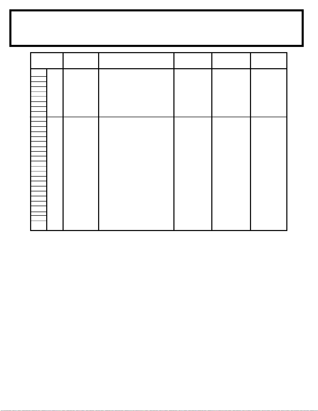
Assembly Part Part
Key No. Number Description Carton 6 Carton 7 Carton 8
65 9479 Bottom Angle 1
66 9504 Weather Strip 1
67 67475 Left Horizontal Track 1
68 67476 Right Horizontal Track 1
69 67666 Right Vertical Track 1
70 67667 Left Vertical Track 1
71 9506 Door Panel 2
72 9507 Door Panel Lock Section 1
73 9508 Door Panel Bottom Section 1
74 9470 Wall Panel 8
75 9491 Roof Panel 8
76 6947 Column Gusset 4
77 6954 Gable/Truss Strut 2
78 6958 Inner Truss Bracket 4
79 6959 Outer Truss Bracket 4
80 6962 Vertical Brace 2
81 6963 Upper Chord 2
82 6964 Lower Chord 2
83 6965 Inner Diagonal Brace 2
84 6966 Outer Diagonal Brace 2
85 6967 Splice Plate 1
86 7003 Left Shear Plate 2
87 7004 Right Shear Plate 2
88 9460 Side Floor Frame 2
89 9461 Side Wall Channel 4
90 9462 Roof Beam 10
91 9463 Side Eave Channel 2
92 9490 Center Column 4
93 9497 Outer Truss Bracket 4
94 9512 Ridge Cap 1
95 9513 Side Roof Trim 2
or Roll-Up-Door & or Roll-Up-Door &
or Roll-Up-Door &
or Roll-Up-Door & or Roll-Up-Door &
VT1431 or 697.68890VT1431 or 697.68890
VT1431 or 697.68890
VT1431 or 697.68890VT1431 or 697.68890
14
Page 15
AssembAssemb
Assemb
AssembAssemb
BX15
ll
y by b
l
y b
ll
y by b
y Ky K
y K
y Ky K
ee
y No. Roll-Up Door & 1431 Buildingy No. Roll-Up Door & 1431 Building
e
y No. Roll-Up Door & 1431 Building
ee
y No. Roll-Up Door & 1431 Buildingy No. Roll-Up Door & 1431 Building
15
Page 16
BX16
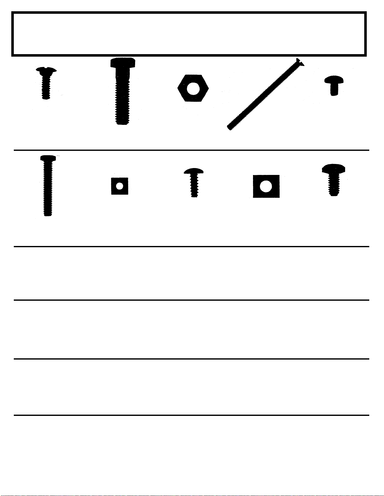
66431 (8)66431 (8)
66431 (8)
66431 (8)66431 (8)
1/4-20x5/8" Rib1/4-20x5/8" Rib
1/4-20x5/8" Rib
1/4-20x5/8" Rib1/4-20x5/8" Rib
Neck BoltNeck Bolt
Neck Bolt
Neck BoltNeck Bolt
HarHar
Har
HarHar
3/8-16x1 1/2" Hex3/8-16x1 1/2" Hex
3/8-16x1 1/2" Hex
3/8-16x1 1/2" Hex3/8-16x1 1/2" Hex
dd
ww
d
w
dd
ww
66432 (4)66432 (4)
66432 (4)
66432 (4)66432 (4)
Head BoltHead Bolt
Head Bolt
Head BoltHead Bolt
arar
ar
arar
e fe f
or Roll-Up-Dooror Roll-Up-Door
e f
or Roll-Up-Door
e fe f
or Roll-Up-Dooror Roll-Up-Door
66434 (2)66434 (2)
66434 (2)
66434 (2)66434 (2)
66433 (4)66433 (4)
66433 (4)
66433 (4)66433 (4)
3/8-16 Hex Nut3/8-16 Hex Nut
3/8-16 Hex Nut
3/8-16 Hex Nut3/8-16 Hex Nut
#10-32 x 2 1/2" Flat#10-32 x 2 1/2" Flat
#10-32 x 2 1/2" Flat
#10-32 x 2 1/2" Flat#10-32 x 2 1/2" Flat
Head BoltHead Bolt
Head Bolt
Head BoltHead Bolt
66441 (14)66441 (14)
66441 (14)
66441 (14)66441 (14)
#10-32x3/8" Bolt#10-32x3/8" Bolt
#10-32x3/8" Bolt
#10-32x3/8" Bolt#10-32x3/8" Bolt
66464 (2)66464 (2)
66464 (2)
66464 (2)66464 (2)
1/4-20x1 1/2" Hex Head1/4-20x1 1/2" Hex Head
1/4-20x1 1/2" Hex Head
1/4-20x1 1/2" Hex Head1/4-20x1 1/2" Hex Head
BoltBolt
Bolt
BoltBolt
6748367483
67483
6748367483
Cable LacerCable Lacer
Cable Lacer
Cable LacerCable Lacer
(2)(2)
(2)
(2)(2)
6748267482
67482
6748267482
Keyed CableKeyed Cable
Keyed Cable
Keyed CableKeyed Cable
(2)(2)
(2)
(2)(2)
6749267492
67492
6749267492
#3 Hinge#3 Hinge
#3 Hinge
#3 Hinge#3 Hinge
(2)(2)
(2)
(2)(2)
65106 (16)65106 (16)
65106 (16)
65106 (16)65106 (16)
#10-32 Square#10-32 Square
#10-32 Square
#10-32 Square#10-32 Square
NutNut
Nut
NutNut
6748467484
67484
6748467484
Spring ClevisSpring Clevis
Spring Clevis
Spring ClevisSpring Clevis
(2)(2)
(2)
(2)(2)
6748567485
67485
6748567485
Left BottomLeft Bottom
Left Bottom
Left BottomLeft Bottom
Bracket (1)Bracket (1)
Bracket (1)
Bracket (1)Bracket (1)
6749467494
67494
6749467494
Lift HandleLift Handle
Lift Handle
Lift HandleLift Handle
(2)(2)
(2)
(2)(2)
65900A (51)65900A (51)
65900A (51)
65900A (51)65900A (51)
#10Bx1/2" Black#10Bx1/2" Black
#10Bx1/2" Black
#10Bx1/2" Black#10Bx1/2" Black
Truss Head ScrewTruss Head Screw
Truss Head Screw
Truss Head ScrewTruss Head Screw
6748867488
67488
6748867488
3/16 x 1 5/16"3/16 x 1 5/16"
3/16 x 1 5/16"
3/16 x 1 5/16"3/16 x 1 5/16"
Heavy "S" HookHeavy "S" Hook
Heavy "S" Hook
Heavy "S" HookHeavy "S" Hook
(4)(4)
(4)
(4)(4)
6748667486
67486
6748667486
Right BottomRight Bottom
Right Bottom
Right BottomRight Bottom
Bracket (1)Bracket (1)
Bracket (1)
Bracket (1)Bracket (1)
6749667496
67496
6749667496
RollerRoller
Roller
RollerRoller
(10)(10)
(10)
(10)(10)
65101 (16)65101 (16)
65101 (16)
65101 (16)65101 (16)
1/4-20 Square Nut1/4-20 Square Nut
1/4-20 Square Nut
1/4-20 Square Nut1/4-20 Square Nut
6750367503
67503
6750367503
Stile SpacerStile Spacer
Stile Spacer
Stile SpacerStile Spacer
(2)(2)
(2)
(2)(2)
6749067490
67490
6749067490
#1 Hinge#1 Hinge
#1 Hinge
#1 Hinge#1 Hinge
(5)(5)
(5)
(5)(5)
6749767497
67497
6749767497
SheaveSheave
Sheave
SheaveSheave
(4)(4)
(4)
(4)(4)
65989 (6)65989 (6)
65989 (6)
65989 (6)65989 (6)
1/4-20x1/2" Hex1/4-20x1/2" Hex
1/4-20x1/2" Hex
1/4-20x1/2" Hex1/4-20x1/2" Hex
Head BoltHead Bolt
Head Bolt
Head BoltHead Bolt
6750467504
67504
6750467504
Inside Latch BarInside Latch Bar
Inside Latch Bar
Inside Latch BarInside Latch Bar
Spacer (1)Spacer (1)
Spacer (1)
Spacer (1)Spacer (1)
6749167491
67491
6749167491
#2 Hinge#2 Hinge
#2 Hinge
#2 Hinge#2 Hinge
(2)(2)
(2)
(2)(2)
6750067500
67500
6750067500
SpringSpring
Spring
SpringSpring
(2)(2)
(2)
(2)(2)
6751367513
67513
6751367513
Spring RestraintSpring Restraint
Spring Restraint
Spring RestraintSpring Restraint
Cable (2)Cable (2)
Cable (2)
Cable (2)Cable (2)
16
6752567525
67525
6752567525
Inside "T" HandleInside "T" Handle
Inside "T" Handle
Inside "T" HandleInside "T" Handle
(1)(1)
(1)
(1)(1)
6752667526
67526
6752667526
Locking HandleLocking Handle
Locking Handle
Locking HandleLocking Handle
(1)(1)
(1)
(1)(1)
67528 Latch Set67528 Latch Set
67528 Latch Set
67528 Latch Set67528 Latch Set
(1) Flat Latch Bar(1) Flat Latch Bar
(1) Flat Latch Bar
(1) Flat Latch Bar(1) Flat Latch Bar
(4) "S" Hooks(4) "S" Hooks
(4) "S" Hooks
(4) "S" Hooks(4) "S" Hooks
(2) Strikers(2) Strikers
(2) Strikers
(2) Strikers(2) Strikers
(2) Spring Latches(2) Spring Latches
(2) Spring Latches
(2) Spring Latches(2) Spring Latches
(2) Latch Chains(2) Latch Chains
(2) Latch Chains
(2) Latch Chains(2) Latch Chains
6766567665
67665
6766567665
Adjustable Top FixtureAdjustable Top Fixture
Adjustable Top Fixture
Adjustable Top FixtureAdjustable Top Fixture
(2)(2)
(2)
(2)(2)
Page 17
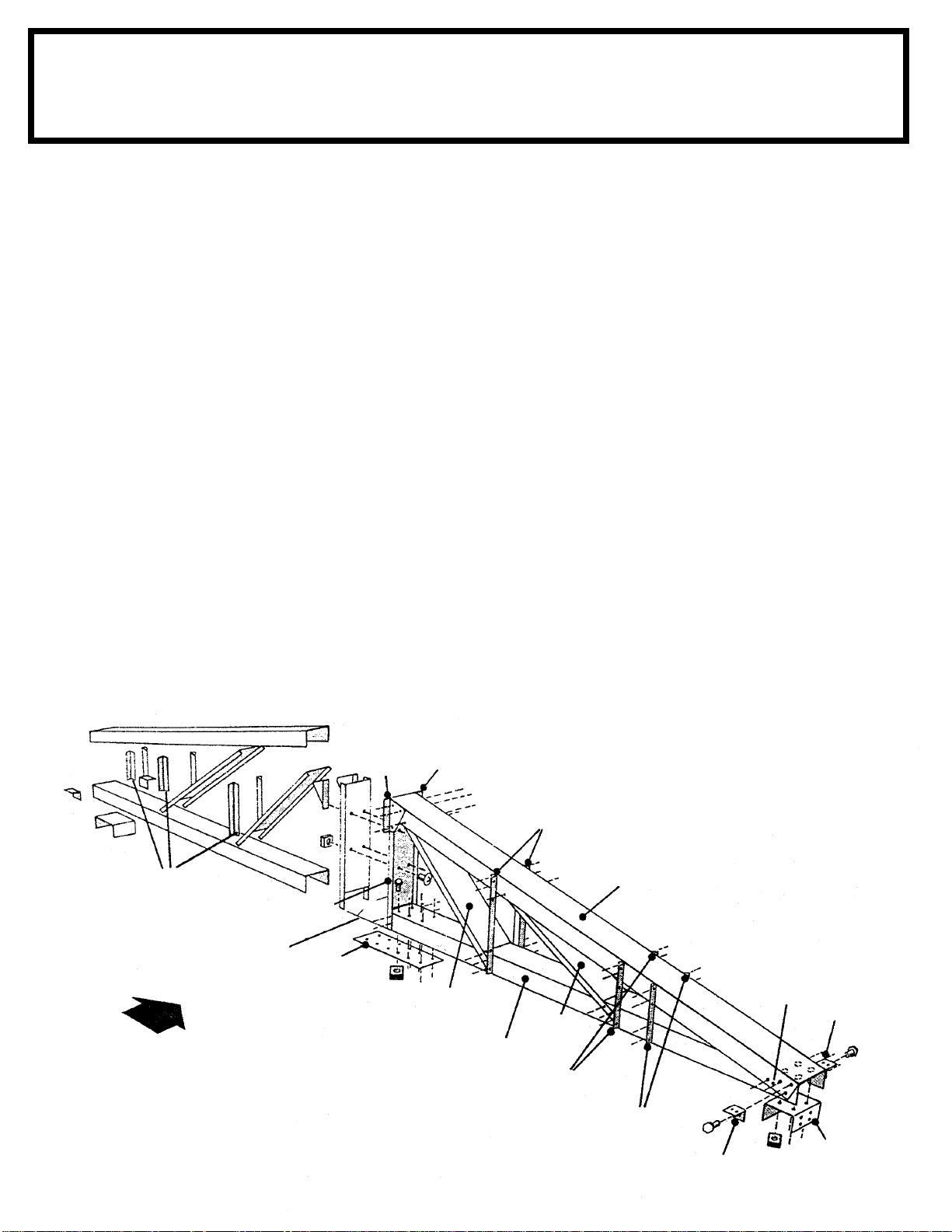
Step 1Step 1
Step 1
Step 1Step 1
BX17
● Parts Needed For ●
TT
rr
uss uss
T
TT
r
uss
rr
uss uss
AssembAssemb
Assemb
AssembAssemb
ll
yy
l
y
ll
yy
●●
6947 Column Gusset (2) 6947 Column Gusset (2)
●
6947 Column Gusset (2)
●●
6947 Column Gusset (2) 6947 Column Gusset (2)
●●
6964 Lower Chord (2) 6964 Lower Chord (2)
●
6964 Lower Chord (2)
●●
6964 Lower Chord (2) 6964 Lower Chord (2)
●●
6963 Upper Chord (2) 6963 Upper Chord (2)
●
6963 Upper Chord (2)
●●
6963 Upper Chord (2) 6963 Upper Chord (2)
●●
7022 Eave Bracket (4) 7022 Eave Bracket (4)
●
7022 Eave Bracket (4)
●●
7022 Eave Bracket (4) 7022 Eave Bracket (4)
●●
6962 Vertical Brace (2) 6962 Vertical Brace (2)
●
6962 Vertical Brace (2)
●●
6962 Vertical Brace (2) 6962 Vertical Brace (2)
●●
7004 Right Shear Plate (2) 7004 Right Shear Plate (2)
●
7004 Right Shear Plate (2)
●●
7004 Right Shear Plate (2) 7004 Right Shear Plate (2)
●●
7003 Left Shear Plate (2) 7003 Left Shear Plate (2)
●
7003 Left Shear Plate (2)
●●
7003 Left Shear Plate (2) 7003 Left Shear Plate (2)
●●
6965 Inner Diagonal Brace (2) 6965 Inner Diagonal Brace (2)
●
6965 Inner Diagonal Brace (2)
●●
6965 Inner Diagonal Brace (2) 6965 Inner Diagonal Brace (2)
●●
6958 Inner Truss Bracket (4) 6958 Inner Truss Bracket (4)
●
6958 Inner Truss Bracket (4)
●●
6958 Inner Truss Bracket (4) 6958 Inner Truss Bracket (4)
●●
6966 Outer Diagonal Brace (2) 6966 Outer Diagonal Brace (2)
●
6966 Outer Diagonal Brace (2)
●●
6966 Outer Diagonal Brace (2) 6966 Outer Diagonal Brace (2)
●●
6959 Outer Truss Bracket (4) 6959 Outer Truss Bracket (4)
●
6959 Outer Truss Bracket (4)
●●
6959 Outer Truss Bracket (4) 6959 Outer Truss Bracket (4)
●●
9497 Outer Truss Bracket (4) 9497 Outer Truss Bracket (4)
●
9497 Outer Truss Bracket (4)
●●
9497 Outer Truss Bracket (4) 9497 Outer Truss Bracket (4)
●●
6967 Splice Plate (1) 6967 Splice Plate (1)
●
6967 Splice Plate (1)
●●
6967 Splice Plate (1) 6967 Splice Plate (1)
1 1
1 Assemble 1/2 truss at a time. At-
1 1
column gusset column gusset
tach
column gusset to
column gusset column gusset
securely using #1/4-20x1/2" hex head
bolts and square nuts. All other connections are to be made loosely.
2 2
2 Fasten
2 2
chordchord
chord and
chordchord
chordchord
chord.
chordchord
3 3
3 Fasten
3 3
chordchord
chord.
chordchord
4 4
4 Fasten
4 4
shear plateshear plate
shear plate to
shear plateshear plate
upper chordupper chord
upper chord.
upper chordupper chord
5 5
5 Fasten
5 5
upper chord upper chord
upper chord and
upper chord upper chord
6 6
6 Fasten 2
6 6
upper chordupper chord
upper chord and
upper chordupper chord
inner diagonal braceinner diagonal brace
inner diagonal brace as shown.
inner diagonal braceinner diagonal brace
lower chordlower chord
lower chord to
lower chordlower chord
eave bracketeave bracket
eave bracket to
eave bracketeave bracket
vertical bracevertical brace
vertical brace to
vertical bracevertical brace
right shear plateright shear plate
right shear plate and
right shear plateright shear plate
vertical bracevertical brace
vertical brace and
vertical bracevertical brace
inner diagonal braceinner diagonal brace
inner diagonal brace to
inner diagonal braceinner diagonal brace
inner truss bracketsinner truss brackets
inner truss brackets to
inner truss bracketsinner truss brackets
lower chord lower chord
lower chord
lower chord lower chord
upperupper
upper
upperupper
upperupper
upper
upperupper
lowerlower
lower
lowerlower
leftleft
left
leftleft
lower chord lower chord
lower chord.
lower chord lower chord
lower chordlower chord
lower chord and
lower chordlower chord
7 7
7 Fasten
7 7
upper chord upper chord
upper chord and
upper chord upper chord
8 8
8 Fasten 2
8 8
upper chord, lower chordupper chord, lower chord
to
upper chord, lower chord and
upper chord, lower chordupper chord, lower chord
outer diagonal braceouter diagonal brace
outer diagonal brace.
outer diagonal braceouter diagonal brace
9 9
9 Fasten 2
9 9
upperupper
to
upper and
upperupper
10 10
10 Square up 1/2 truss, adjust and
10 10
tighten all fasteners.
1111
11Assemble the other half of truss.
1111
1212
12Splice both halves together with
1212
splice platesplice plate
the
splice plate and join the (4)
splice platesplice plate
#10-32x7/16" bolts and square nuts
through
Make 1 assembly for the 14x21.
Make 2 assemblies for the 14x31.
outer diagonal braceouter diagonal brace
outer diagonal brace to
outer diagonal braceouter diagonal brace
lower chord lower chord
lower chord.
lower chord lower chord
outer truss bracketsouter truss brackets
outer truss brackets
outer truss bracketsouter truss brackets
outer truss bracketsouter truss brackets
outer truss brackets
outer truss bracketsouter truss brackets
lower chordslower chords
lower chords.
lower chordslower chords
vertical bracevertical brace
vertical brace.
vertical bracevertical brace
Mounting Flange of Brackets
Must Face Towards Center
Of Truss Assembly
IMPORTANT:IMPORTANT:
IMPORTANT:
IMPORTANT:IMPORTANT:
Square Up
Half Truss
FRONTFRONT
FRONT
FRONTFRONT
6962
6967
7004
o
90
7003
6965
6964
6958
6966
6959
6963
9497
7022
Leave Hole On
This Side Open
For Track Strut
7022
6947
17
Page 18
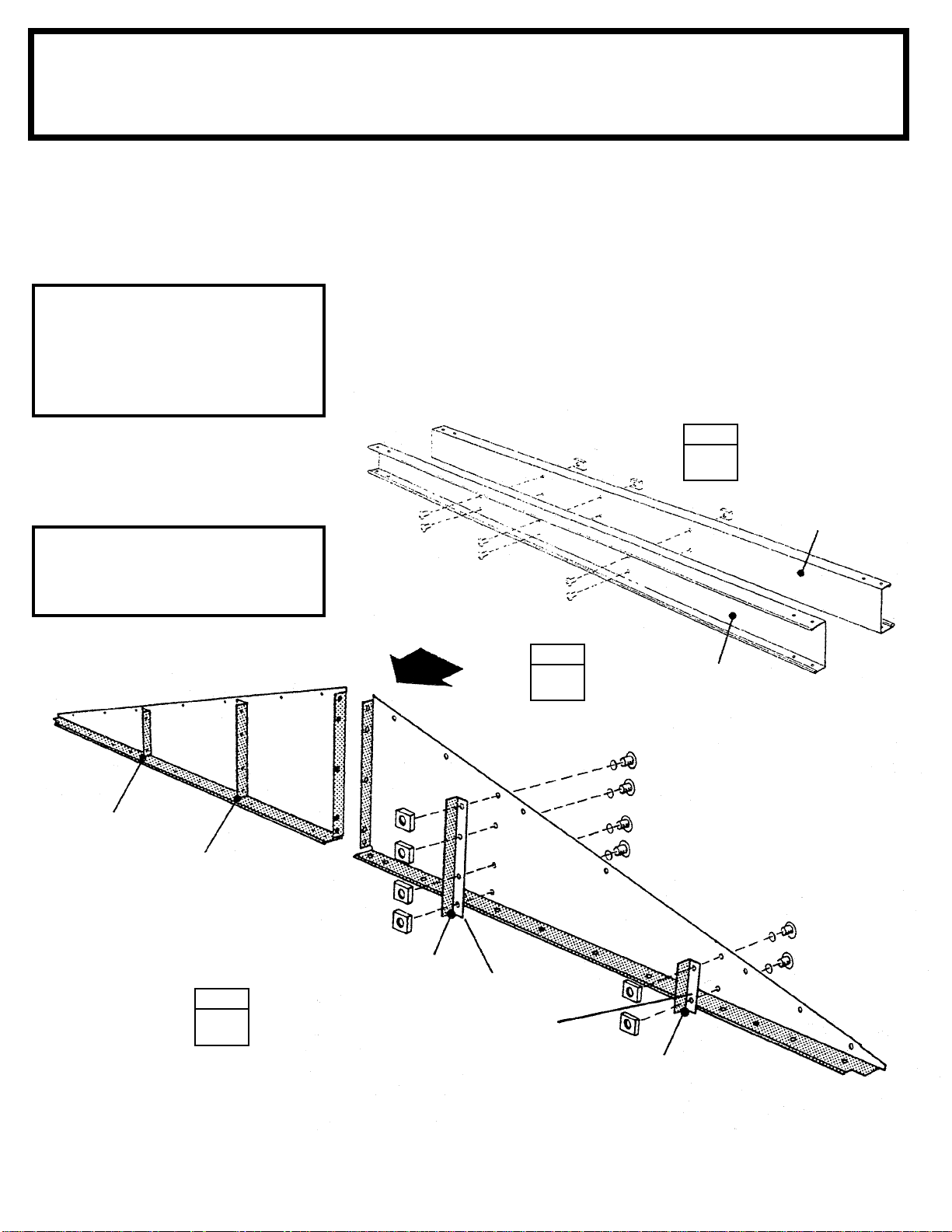
Step 2Step 2
Step 2
Step 2Step 2
BX18
GaGa
Ga
GaGa
● Parts Needed For ●
bb
les/Column les/Column
b
les/Column
bb
les/Column les/Column
AssembAssemb
Assemb
AssembAssemb
lieslies
lies
lieslies
●●
9494 Right Gable (2) 9494 Right Gable (2)
●
9494 Right Gable (2)
●●
9494 Right Gable (2) 9494 Right Gable (2)
●●
9495 Left Gable (2) 9495 Left Gable (2)
●
9495 Left Gable (2)
●●
9495 Left Gable (2) 9495 Left Gable (2)
●●
6955 Inner Gable Bracket (4) 6955 Inner Gable Bracket (4)
●
6955 Inner Gable Bracket (4)
●●
6955 Inner Gable Bracket (4) 6955 Inner Gable Bracket (4)
●●
9496 Outer Gable Bracket (4) 9496 Outer Gable Bracket (4)
●
9496 Outer Gable Bracket (4)
●●
9496 Outer Gable Bracket (4) 9496 Outer Gable Bracket (4)
●●
9490 Center Column (6 14x21) (10 14x31) 9490 Center Column (6 14x21) (10 14x31)
●
9490 Center Column (6 14x21) (10 14x31)
●●
9490 Center Column (6 14x21) (10 14x31) 9490 Center Column (6 14x21) (10 14x31)
The gables go on top of the front and
rear walls to support the roof beams.
The center columns support the truss
and the framework.
NOTENOTE
NOTE
NOTENOTE
The gables are packed nested
together and might be mistaken
as one piece. Carefully separate
them before continuing.
1 1
1 Attach the
1 1
bracketsbrackets
brackets to the gables using bolts,
bracketsbrackets
washers and nuts where shown.
Mounting leg of bracket must face
toward outside of building.
innerinner
inner and
innerinner
NOTENOTE
NOTE
NOTENOTE
outer gableouter gable
outer gable
outer gableouter gable
FRONTFRONT
FRONT
FRONTFRONT
STEP
33
3
33
22
2 Align the holes on the
22
columnscolumns
columns back to back and fasten
columnscolumns
together using 6 bolts and nuts.
Make 3 assemblies for the 14x21.
Make 5 assemblies for the 14x31.
33
3Set these pieces aside for later as-
33
sembly.
STEP
22
2
22
9490
9490
centercenter
center
centercenter
18
9496
6955
STEP
9494
6955
Attach Narrow Flange
of Gable Brackets
11
1
11
to Gable
Washer
9495
Washer
9496
Page 19
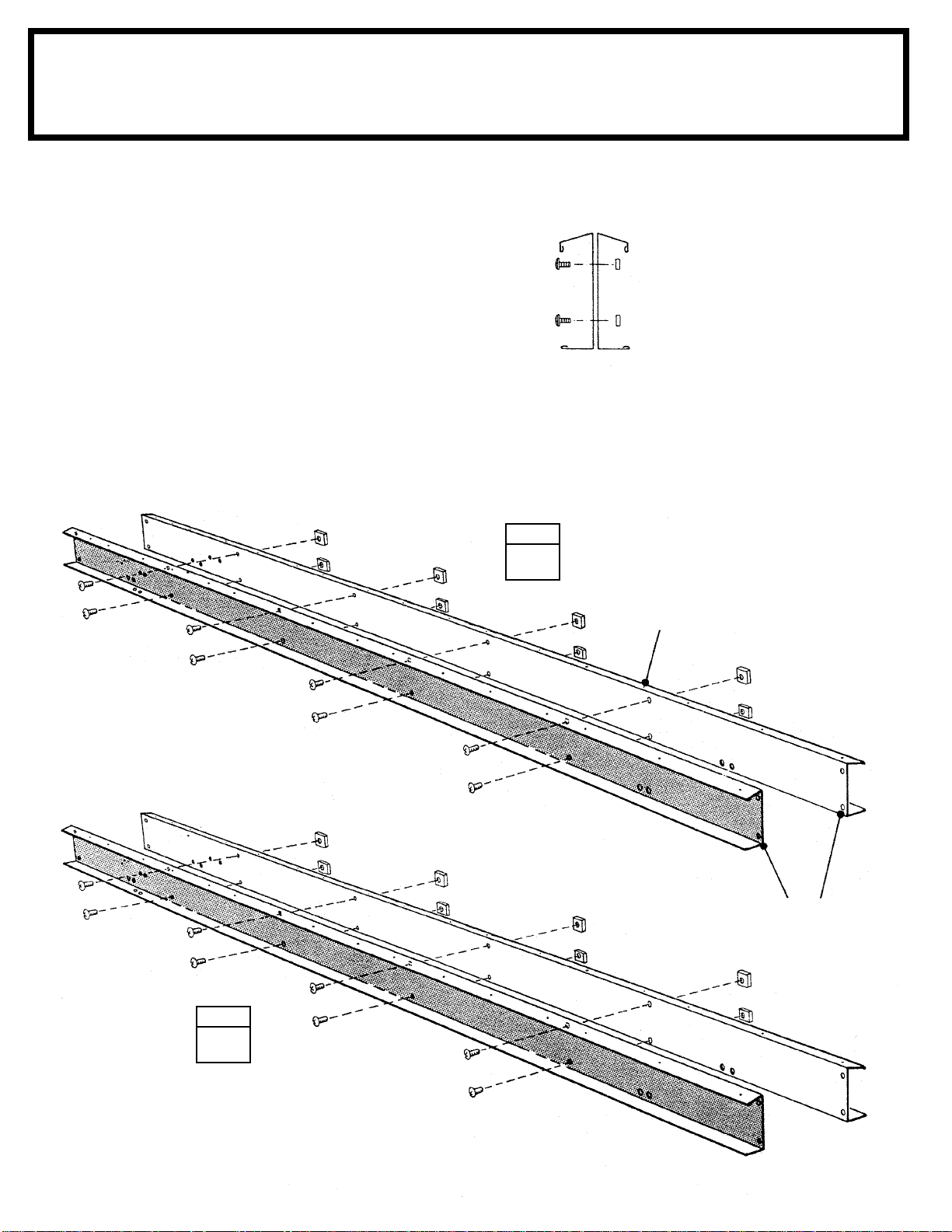
Step 3Step 3
Step 3
Step 3Step 3
BX19
The roof beams join the gables to the
truss and supports the roof panels.
● Parts Needed For ●
Roof Beam Roof Beam
Roof Beam
Roof Beam Roof Beam
AssembAssemb
Assemb
AssembAssemb
lieslies
lies
lieslies
Assembled
●●
9502 Right Roof Beam (10) 9502 Right Roof Beam (10)
●
9502 Right Roof Beam (10)
●●
9502 Right Roof Beam (10) 9502 Right Roof Beam (10)
●●
9503 Left Roof Beam (10) 9503 Left Roof Beam (10)
●
9503 Left Roof Beam (10)
●●
9503 Left Roof Beam (10) 9503 Left Roof Beam (10)
●●
9462 Roof Beam (10 14x31) 9462 Roof Beam (10 14x31)
●
9462 Roof Beam (10 14x31)
●●
9462 Roof Beam (10 14x31) 9462 Roof Beam (10 14x31)
1 1
1 Align the holes on a
1 1
roof beamroof beam
roof beam back-to-back and fasten
roof beamroof beam
together using 8 bolts and nuts. Make
10 assemblies.
2 2
2 On the 14x31 fasten
2 2
together in the same manner. Make
5 assemblies.
left left
left and
left left
roof beamsroof beams
roof beams
roof beamsroof beams
9503
right right
right
right right
9502
STEP
11
1
11
End
View
Small Holes
on Top
9496
STEP
22
2
22
9462
9462
Align End Holes
Before Tightening
Bolts and Nuts
19
Page 20
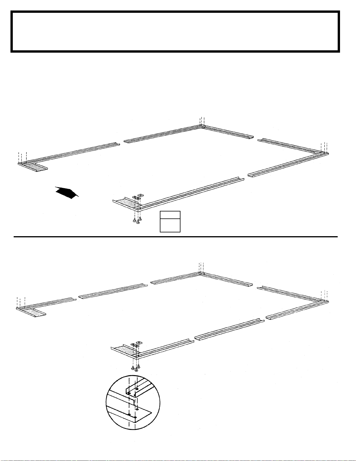
Step 4Step 4
Step 4
Step 4Step 4
BX20
1 1
1 Place the floor frame pieces on the
1 1
foundation. Assemble the 4 corners
of the floor frame using 3 bolts from
the bottom with nuts on top at each
corner as shown.
● Parts Needed For ●
Floor FFloor F
Floor F
Floor FFloor F
rr
ame ame
r
ame
rr
ame ame
AssembAssemb
Assemb
AssembAssemb
●●
9481 Front Frame (1) 9481 Front Frame (1)
●
9481 Front Frame (1)
●●
9481 Front Frame (1) 9481 Front Frame (1)
●●
9480 Front Frame (1) 9480 Front Frame (1)
●
9480 Front Frame (1)
●●
9480 Front Frame (1) 9480 Front Frame (1)
●●
9475 Side Floor Frame (4) 9475 Side Floor Frame (4)
●
9475 Side Floor Frame (4)
●●
9475 Side Floor Frame (4) 9475 Side Floor Frame (4)
●●
6939 Rear Frame (1) 6939 Rear Frame (1)
●
6939 Rear Frame (1)
●●
ll
yy
l
y
ll
yy
6939 Rear Frame (1) 6939 Rear Frame (1)
●●
6938 Rear Frame (1) 6938 Rear Frame (1)
●
6938 Rear Frame (1)
●●
6938 Rear Frame (1) 6938 Rear Frame (1)
●●
9460 Side Floor Frame (2 14x31) 9460 Side Floor Frame (2 14x31)
●
9460 Side Floor Frame (2 14x31)
●●
9460 Side Floor Frame (2 14x31) 9460 Side Floor Frame (2 14x31)
9480
9475
FRONT
9460
9481
9475
(1421)
STEP
11
1
11
9475
6939
6938
9475
9475
6939
6938
20
9480
9475
9481
(1431)
9475
9460
9475
Page 21
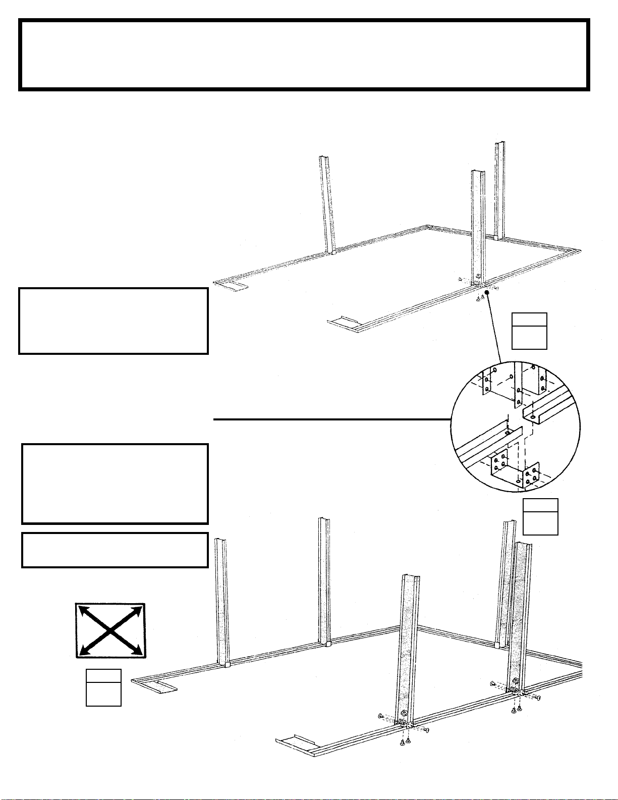
Step 5Step 5
Step 5
Step 5Step 5
BX21
1 1
1 Fasten side floor frames together
1 1
with a
from the bottom and nuts on top. At
rear of building, repeat procedure.
column gussetcolumn gusset
column gusset using 2 bolts
column gussetcolumn gusset
● Parts Needed For ●
Gusset/Center ColumnGusset/Center Column
Gusset/Center Column
Gusset/Center ColumnGusset/Center Column
●●
6947 Column Gusset (3 14x21) (5 14x31) 6947 Column Gusset (3 14x21) (5 14x31)
●
6947 Column Gusset (3 14x21) (5 14x31)
●●
6947 Column Gusset (3 14x21) (5 14x31) 6947 Column Gusset (3 14x21) (5 14x31)
●●
Center Column Assembly (3 14x21) Center Column Assembly (3 14x21)
●
Center Column Assembly (3 14x21)
●●
Center Column Assembly (3 14x21) Center Column Assembly (3 14x21)
●●
Center Column Assembly (5 14x31) Center Column Assembly (5 14x31)
●
Center Column Assembly (5 14x31)
●●
Center Column Assembly (5 14x31) Center Column Assembly (5 14x31)
9490
2 2
2 Position center column assem-
2 2
blies where floor frames are joined
and fasten to gusset with 8 bolts.
Repeat procedure on sides of building for the 14x31.
NOTENOTE
NOTE
NOTENOTE
Support center columns with
stakes or other means until wall
panels are attached.
3 3
3 Measure the floor frame diago-
3 3
nally. When the diagonal measurements are equal, the floor frame is
square.
NOTENOTE
NOTE
NOTENOTE
Do not fasten the floor frames to
your foundation at this time.
You will anchor the building
after it is erected.
FRONT
9490
6947
(1421)
9490
6947
6947
STEP
22
2
22
STEP
11
1
11
The floor frame The floor frame
The floor frame
The floor frame The floor frame
and level and level
and level
and level and level
or holes will not align.or holes will not align.
or holes will not align.
or holes will not align.or holes will not align.
33
3
33
must be squaremust be square
must be square
must be squaremust be square
9490
6947STEP
FRONT
6947
9490
9490
9490
9490
6947
(1431)
6947
6947
21
Page 22
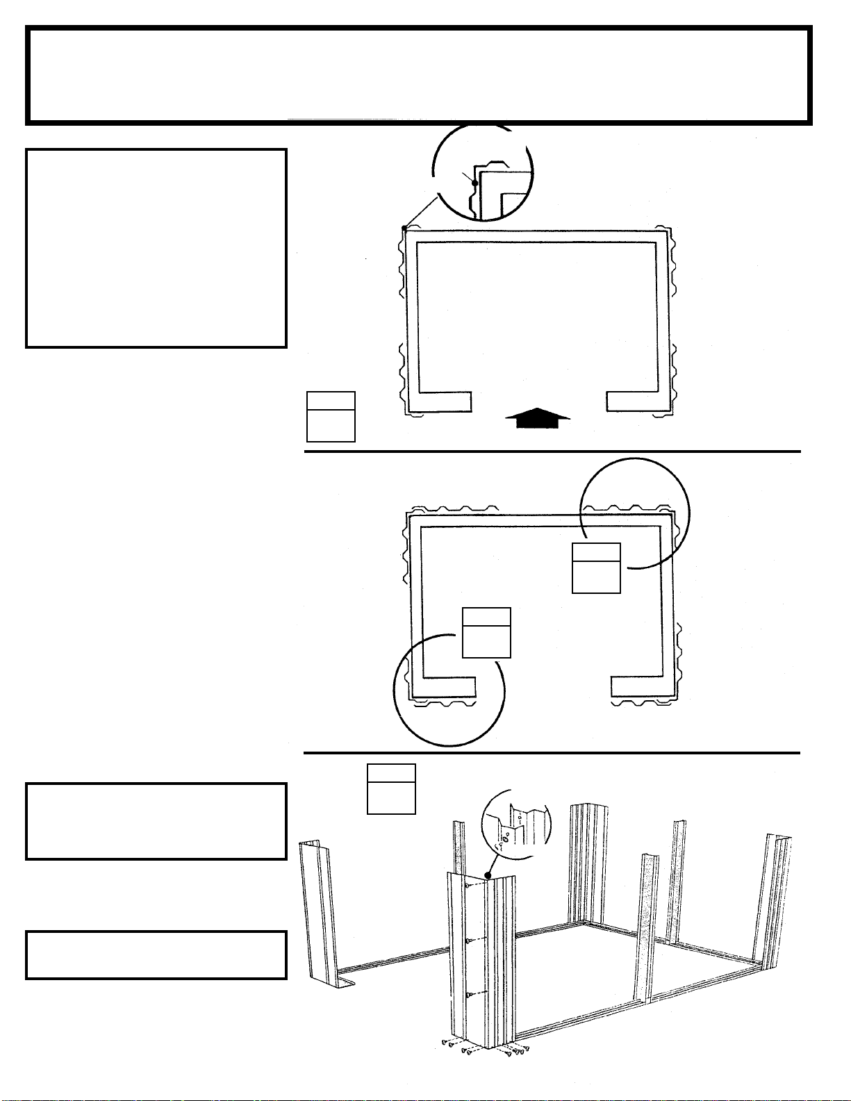
Step 6Step 6
Step 6
Step 6Step 6
BX22
NOTENOTE
NOTE
NOTENOTE
The remainder of the building
assembly requires many hours
and more than one person. Tie
down and support assembly
before the end of the work day.
A partially assembled building
can be severely damaged by
light winds.
Each screw and bolt in the wall requires a washer.
1 1
1 Position a
1 1
corner of the floor frame as shown.
The widest part of each corner panel
must be placed along the side of the
building for all 4 corners. Fasten the
corner panel to the floor frame with 4
screws.
Support the corner panel with a step
ladder until a wall panel is attached.
corner panelcorner panel
corner panel at the
corner panelcorner panel
● Parts Needed For ●
CornersCorners
Corners
CornersCorners
Narrow
Side
9472
Wide Side
SIDE
STEP
11
1
11
9472
9471
STEP
REAR
TOP VIEW
FRONT
STEP
33
3
33
●●
9471 Wall Panel (2) 9471 Wall Panel (2)
●
9471 Wall Panel (2)
●●
9471 Wall Panel (2) 9471 Wall Panel (2)
●●
9473 Front Wall Panel (2) 9473 Front Wall Panel (2)
●
9473 Front Wall Panel (2)
●●
9473 Front Wall Panel (2) 9473 Front Wall Panel (2)
●●
9472 Corner Panel (4) 9472 Corner Panel (4)
●
9472 Corner Panel (4)
●●
9472 Corner Panel (4) 9472 Corner Panel (4)
9472
SIDE
9472
9471
2 2
2 Attach the
2 2
front corner panels, as shown.
3 3
3 Attach the
3 3
corner panels, as shown.
Be careful to install the correct
panel in each position as shown.
4 4
4 Double-check the part numbers of
4 4
the wall panels, before proceeding.
The floor frame The floor frame
The floor frame
The floor frame The floor frame
and level and level
and level
and level and level
front wall panelsfront wall panels
front wall panels to the
front wall panelsfront wall panels
wall panelswall panels
wall panels to the rear
wall panelswall panels
NOTENOTE
NOTE
NOTENOTE
must be squaremust be square
must be square
must be squaremust be square
or holes will not align.or holes will not align.
or holes will not align.
or holes will not align.or holes will not align.
9472
9473
STEP
44
4
44
9473
9473
22
2
22
Crimped Rib
Underneath
Washer
9472
9472
9473
9471
9471
9472
22
Page 23
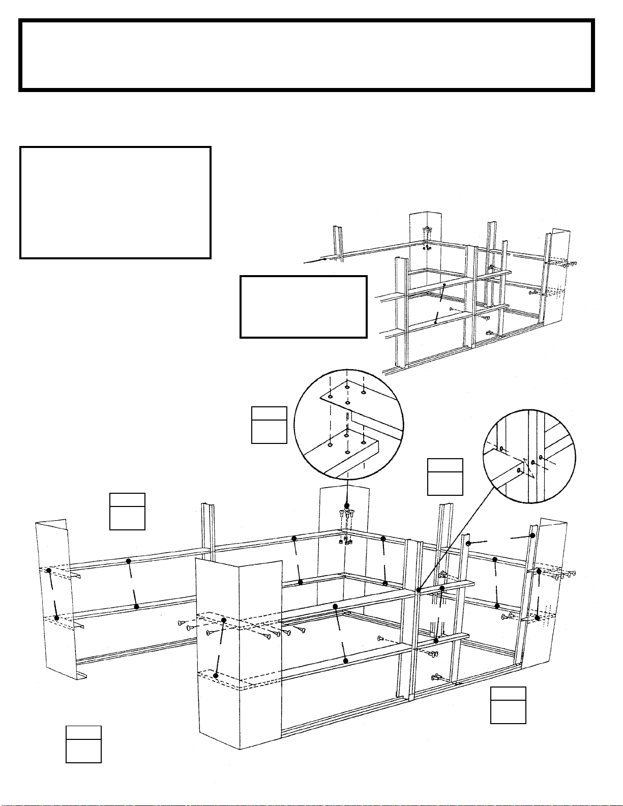
Step 7Step 7
Step 7
Step 7Step 7
BX23
● Parts Needed For ●
Mid FramesMid Frames
Mid Frames
Mid FramesMid Frames
●●
9482 Right Front Wall Channel (2) 9482 Right Front Wall Channel (2)
●
9482 Right Front Wall Channel (2)
●●
9482 Right Front Wall Channel (2) 9482 Right Front Wall Channel (2)
●●
9483 Left Front Wall Channel (2) 9483 Left Front Wall Channel (2)
●
9483 Left Front Wall Channel (2)
●●
9483 Left Front Wall Channel (2) 9483 Left Front Wall Channel (2)
●●
9476 Side Wall Channel (6) 9476 Side Wall Channel (6)
●
9476 Side Wall Channel (6)
●●
9476 Side Wall Channel (6) 9476 Side Wall Channel (6)
●●
6942 Right Rear Wall Channel (2) 6942 Right Rear Wall Channel (2)
●
6942 Right Rear Wall Channel (2)
●●
6942 Right Rear Wall Channel (2) 6942 Right Rear Wall Channel (2)
●●
6943 Left Rear Wall Channel (2) 6943 Left Rear Wall Channel (2)
●
6943 Left Rear Wall Channel (2)
●●
6943 Left Rear Wall Channel (2) 6943 Left Rear Wall Channel (2)
●●
9465 Support Column (2) 9465 Support Column (2)
●
9465 Support Column (2)
●●
9465 Support Column (2) 9465 Support Column (2)
●●
9469 Side Door Channel (2) 9469 Side Door Channel (2)
●
9469 Side Door Channel (2)
●●
9469 Side Door Channel (2) 9469 Side Door Channel (2)
●●
9468 Corner Door Channel (2) 9468 Corner Door Channel (2)
●
9468 Corner Door Channel (2)
●●
9468 Corner Door Channel (2) 9468 Corner Door Channel (2)
●●
9461 Side Wall Channel (4 14x31) 9461 Side Wall Channel (4 14x31)
●
9461 Side Wall Channel (4 14x31)
●●
9461 Side Wall Channel (4 14x31) 9461 Side Wall Channel (4 14x31)
The mid frame pieces give rigidity to
the sides and rear wall.
NOTENOTE
NOTE
NOTENOTE
Before installing side wall
channels decide at which location
you want the side entrance door.
Do not install the 1x4 side wall
channels at 1 of the 4 corner loca-
tions.
1 1
1 Fasten
1 1
side wall channelsside wall channels
side wall channels to
side wall channelsside wall channels
center columns using 2 bolts and to
corner panels using 4 screws.
2 2
2 Overlap with the
2 2
front wall channelsfront wall channels
front wall channels and fasten to
front wall channelsfront wall channels
rightright
right and
rightright
leftleft
left
leftleft
front wall panel using 3 screws. Do
not fasten hole nearest door opening.
5 5
5 Install
5 5
floor frame and
support columnsupport column
support column to side
support columnsupport column
side door channelside door channel
side door channel
side door channelside door channel
fastening channel to center column.
Install 2nd
floor frame and
nelnel
nel. Fasten channel to corner panel
nelnel
support columnsupport column
support column to side
support columnsupport column
corner door chan-corner door chan-
corner door chan-
corner door chan-corner door chan-
and left rear wall channel.
9461
NOTE
On the 1431, attach the side
wall channel between the
center columns using bolts
and nuts.
FRONT
9461
3 3
3 Overlap with
3 3
wall channelswall channels
wall channels and fasten to column
wall channelswall channels
right right
right and
right right
left rearleft rear
left rear
left rearleft rear
and wall panel.
4 4
4 Fasten overlaps using 4 bolts and
4 4
nuts in each corner assembly.
STEP
11
1
11
9476
9483
FRONT
9482
STEP
44
4
44
9476
9476
6942
STEP
33
3
33
9469
9465
6943
STEP
9468
55
5
55
STEP
22
2
22
23
Page 24
Step 8Step 8
Step 8
Step 8Step 8
BX24
● Parts Needed For ●
Side Door FramesSide Door Frames
Side Door Frames
Side Door FramesSide Door Frames
●●
9484 Right Side Eave Channel (1) 9484 Right Side Eave Channel (1)
●
9484 Right Side Eave Channel (1)
●●
9484 Right Side Eave Channel (1) 9484 Right Side Eave Channel (1)
●●
7562 Track (1) 7562 Track (1)
●
7562 Track (1)
●●
7562 Track (1) 7562 Track (1)
●●
9467 Ramp (1) 9467 Ramp (1)
●
9467 Ramp (1)
●●
9467 Ramp (1) 9467 Ramp (1)
●●
9464 Lower Door Track (1) 9464 Lower Door Track (1)
●
9464 Lower Door Track (1)
●●
9464 Lower Door Track (1) 9464 Lower Door Track (1)
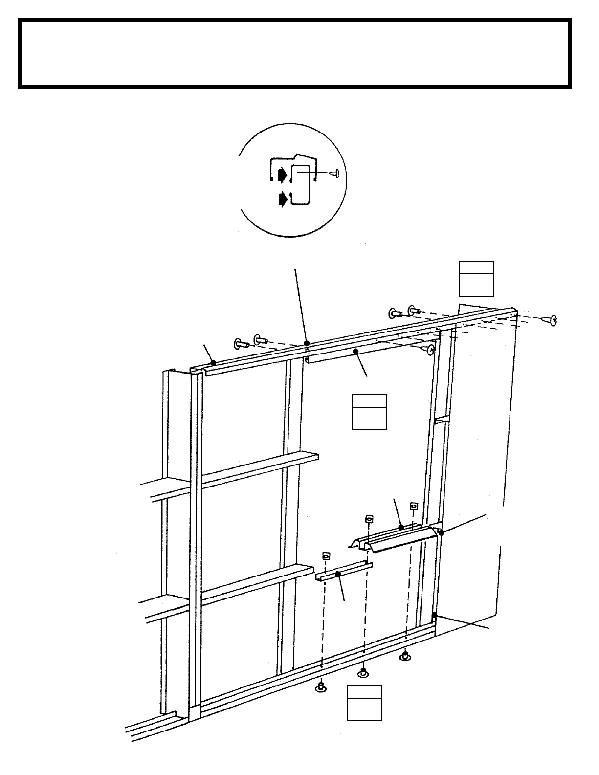
1 1
1 Position
1 1
against support columns. Fasten
channel to corner panel. Fasten columns to side eave channel using 2
bolts and nuts on each column.
2 2
2 Position
2 2
the side floor frame. Overlap with
rampramp
ramp and fasten from the bottom us-
rampramp
ing (3) #10-32x1/4" slotted head bolts
and square nuts.
3 3
3 Position
3 3
eave channel, directly over lower door
track and ramp, and fasten using 4
screws where shown.
right side eave channelright side eave channel
right side eave channel
right side eave channelright side eave channel
lower door tracklower door track
lower door track inside
lower door tracklower door track
tracktrack
track inside right side
tracktrack
9484
Long Leg
on Top
Short Leg
on Bottom
Opening
Facing In
7562
STEP
11
1
11
9464
STEP
33
3
33
9467
Notch Toward
Outside of
Building
1/2" Between
Ramp & Panel
24
STEP
22
2
22
Page 25
Step 9Step 9
Step 9
Step 9Step 9
BX25
● Parts Needed For ●
Front/Rear FramesFront/Rear Frames
Front/Rear Frames
Front/Rear FramesFront/Rear Frames
●●
9474 Lintel (1) 9474 Lintel (1)
●
9474 Lintel (1)
●●
9474 Lintel (1) 9474 Lintel (1)
●●
9481 Front Frame (1) 9481 Front Frame (1)
●
9481 Front Frame (1)
●●
9481 Front Frame (1) 9481 Front Frame (1)
●●
9480 Front Frame (1) 9480 Front Frame (1)
●
9480 Front Frame (1)
●●
9480 Front Frame (1) 9480 Front Frame (1)
●●
9478 Front Column (2) 9478 Front Column (2)
●
9478 Front Column (2)
●●
9478 Front Column (2) 9478 Front Column (2)
●●
6947 Column Gusset (1) 6947 Column Gusset (1)
●
6947 Column Gusset (1)
●●
6947 Column Gusset (1) 6947 Column Gusset (1)
●●
6938 Rear Frame (1) 6938 Rear Frame (1)
●
6938 Rear Frame (1)
●●
6938 Rear Frame (1) 6938 Rear Frame (1)
●●
6939 Rear Frame (1) 6939 Rear Frame (1)
●
6939 Rear Frame (1)
●●
6939 Rear Frame (1) 6939 Rear Frame (1)
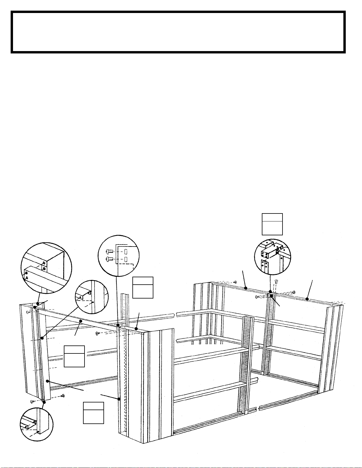
1 1
1 Fasten
1 1
front frames front frames
front frames at the top to
front frames front frames
front wall panels with 3 screws. Do
not fasten hole nearest door opening
at this time.
2 2
2 Fasten
2 2
front columnsfront columns
front columns to the frame
front columnsfront columns
at bottom and channel with 2 bolts.
Hint: Hint:
Hint: Pull front wall panel slightly
Hint: Hint:
away to tighten bolts.
3 3
3 Position
3 3
lintellintel
lintel across top of front
lintellintel
frames and fasten with 2 bolts and
nuts on both sides.
4 4
4 Position
4 4
column gusset column gusset
column gusset over rear
column gusset column gusset
columns and fasten with 8 bolts. At-
rear framesrear frames
tach
rear frames to gusset using 2
rear framesrear frames
bolts and opposite end to wall panel
using 3 screws.
STEP
44
4
44
9481
9474
STEP
33
3
33
9478
STEP
22
2
22
STEP
11
1
11
9480
6938
6939
6947
25
Page 26
Step 10Step 10
Step 10
Step 10Step 10
BX26
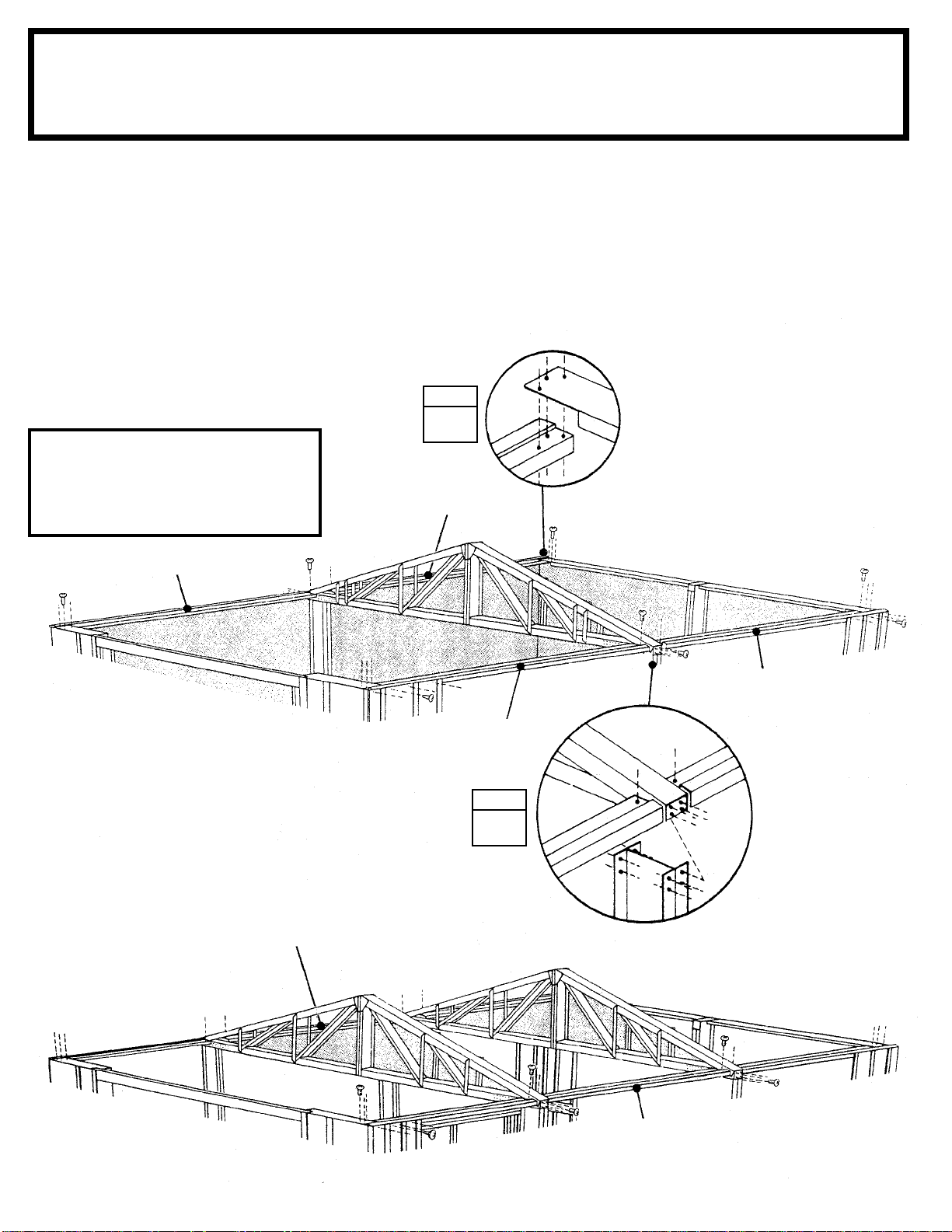
1 1
1 Position Truss Assembly on build-
1 1
ing by sliding column gussets over
center columns and fasten with 8
bolts and nuts on each gusset.
● Parts Needed For ●
TT
rr
T
TT
r
rr
uss/Tuss/T
uss/T
uss/Tuss/T
op Fop F
op F
op Fop F
rr
amesames
r
ames
rr
amesames
●●
Truss Assembly (1 14x21) (2 14x31) Truss Assembly (1 14x21) (2 14x31)
●
Truss Assembly (1 14x21) (2 14x31)
●●
Truss Assembly (1 14x21) (2 14x31) Truss Assembly (1 14x21) (2 14x31)
●●
9484 Right Side Eave Channel (2) 9484 Right Side Eave Channel (2)
●
9484 Right Side Eave Channel (2)
●●
9484 Right Side Eave Channel (2) 9484 Right Side Eave Channel (2)
●●
9485 Left Side Eave Channel (2) 9485 Left Side Eave Channel (2)
●
9485 Left Side Eave Channel (2)
●●
9485 Left Side Eave Channel (2) 9485 Left Side Eave Channel (2)
●●
9463 Side Eave Channel (2 14x31) 9463 Side Eave Channel (2 14x31)
●
9463 Side Eave Channel (2 14x31)
●●
9463 Side Eave Channel (2 14x31) 9463 Side Eave Channel (2 14x31)
2 2
2 Position
2 2
channelschannels
channels over eave brackets and
channelschannels
fasten with a bolt and nut. Front and
rear frames overlap side eave channels. Fasten overlaps with 3 bolts
and nuts. Fasten corner panels to
channels using 4 screws.
On the 1431, fasten the side
eave channels over eave brackets
rightright
right and
rightright
NOTENOTE
NOTE
NOTENOTE
using bolts and nuts.
9484
left side eaveleft side eave
left side eave
left side eaveleft side eave
STEP
22
2
22
9485
(1421)
9484 Installed in Step 8
9463
9485
STEP
11
1
11
(1431)
9463
26
Page 27
Step 11Step 11
Step 11
Step 11Step 11
BX27
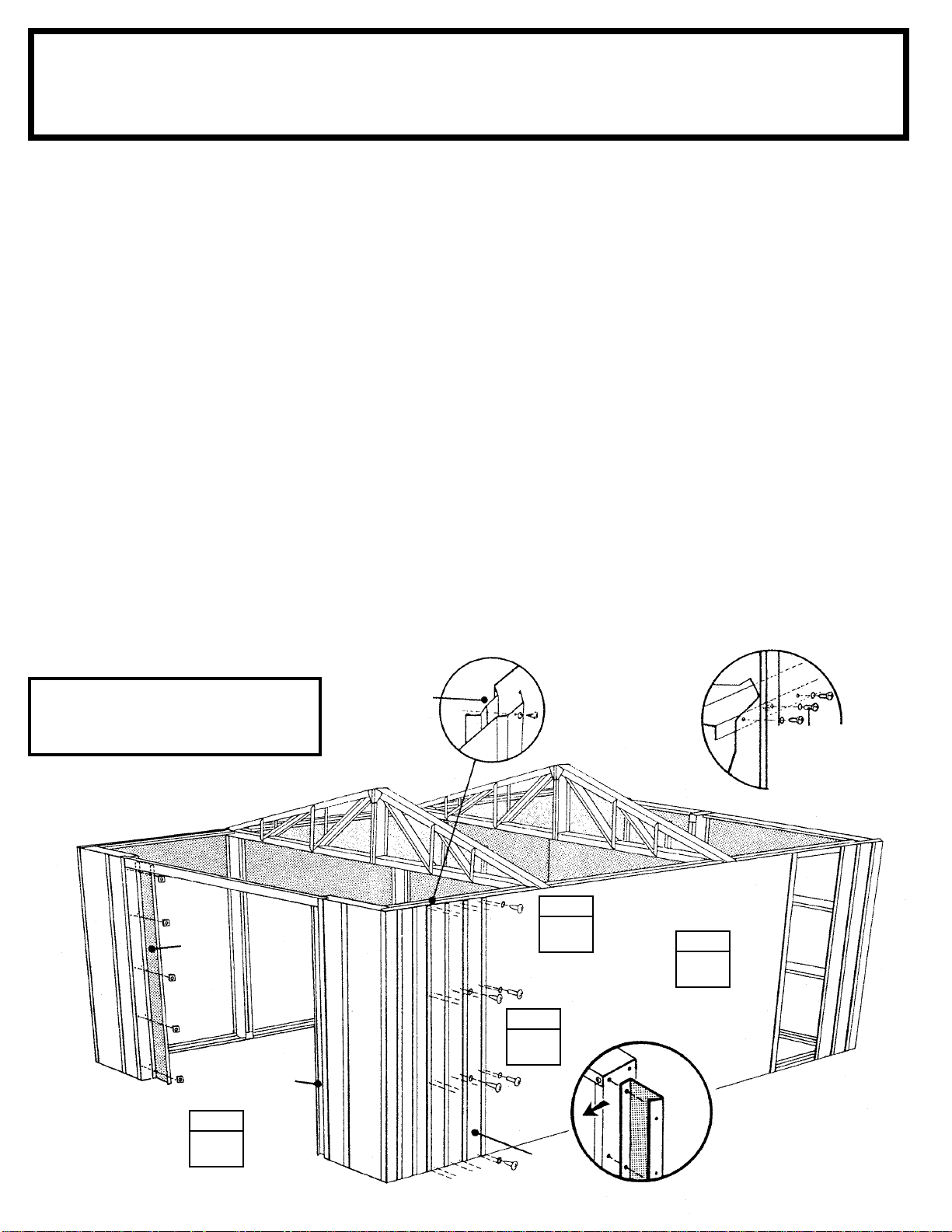
Each wall panel has a crimped rib on
1 side. The crimped rib should go
under the rib of the panel that follows
it.
WW
W
WW
● Parts Needed For ●
alls Palls P
alls P
alls Palls P
anels/Tanels/T
anels/T
anels/Tanels/T
rr
acac
r
ac
rr
acac
k Suppork Suppor
k Suppor
k Suppork Suppor
tsts
ts
tsts
●●
9470 Wall Panel (17 14x21) (8 14x31) 9470 Wall Panel (17 14x21) (8 14x31)
●
9470 Wall Panel (17 14x21) (8 14x31)
●●
9470 Wall Panel (17 14x21) (8 14x31) 9470 Wall Panel (17 14x21) (8 14x31)
●●
9486 Right Track Support (1) 9486 Right Track Support (1)
●
9486 Right Track Support (1)
●●
9486 Right Track Support (1) 9486 Right Track Support (1)
●●
9487 Left Track Support (1) 9487 Left Track Support (1)
●
9487 Left Track Support (1)
●●
9487 Left Track Support (1) 9487 Left Track Support (1)
1 1
1 Fasten the
1 1
and bottom with screws.
2 2
2 Fasten the center of each panel to
2 2
the wall channel with screws. Fasten
overlapping ribs using screws and
bolts with nuts.
3 3
3 When you have attached all wall
3 3
panels in the correct positions, the
building will look like this.
4 4
4 Fasten
4 4
portsports
ports to the front columns using 5
portsports
bolts from the inside and nuts outside.
Flanges on track supports
face
towards front of building.
wall panelswall panels
wall panels at the top
wall panelswall panels
rightright
right and
rightright
NOTENOTE
NOTE
NOTENOTE
left track sup-left track sup-
left track sup-
left track sup-left track sup-
must
Detail Showing
Center of Panel Screwed
to Wall Channel
Crimped Rib
Underneath
Bolt and nut
does not go
thru wall channel
at overlap
9487
STEP
STEP
11
1
11
STEP
22
2
22
9486
44
4
44
9470
INSIDE
BUILDING
9487
STEP
33
3
33
27
Page 28
Step 12Step 12
Step 12
Step 12Step 12
BX28
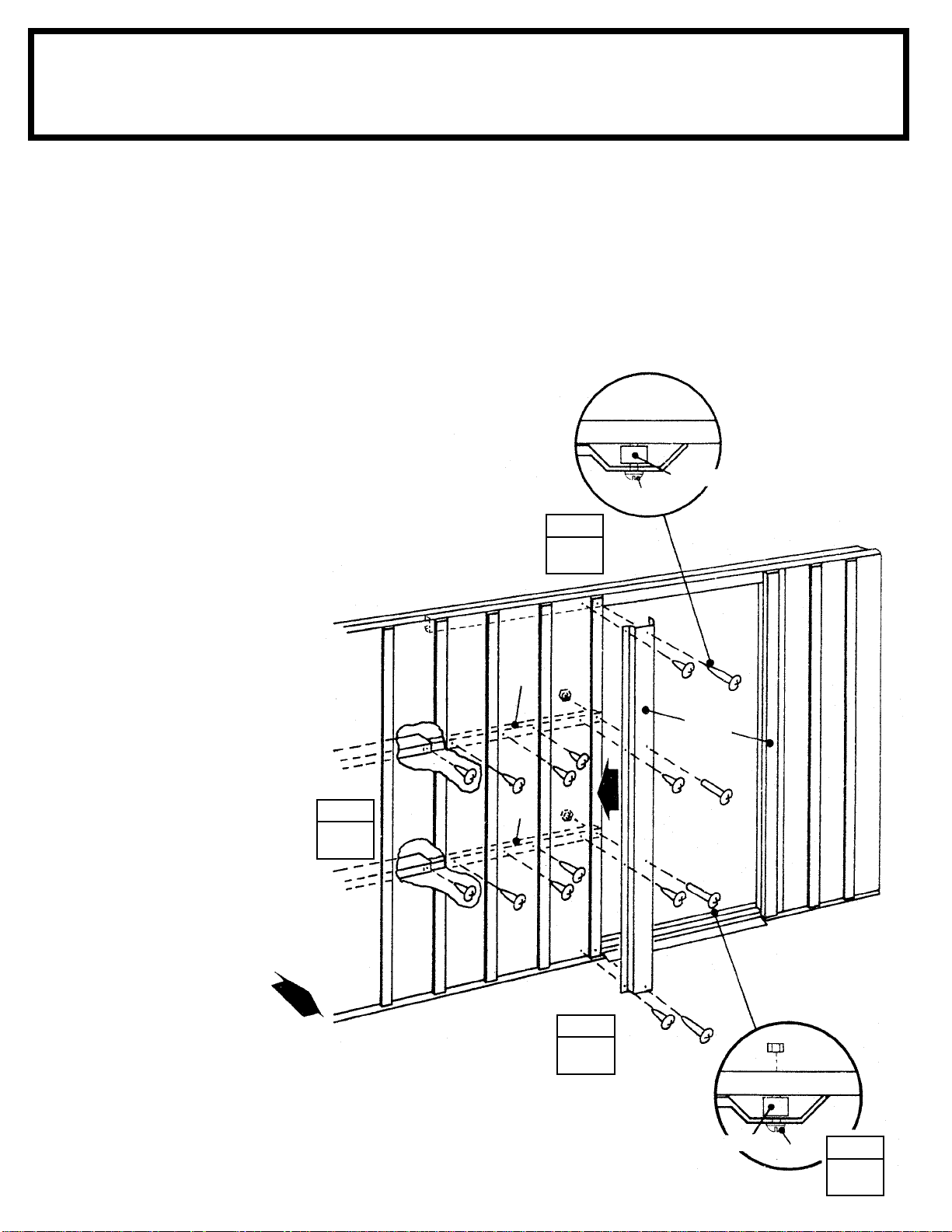
The door jambs reinforce the door
opening and provide an attractive
trim. Follow these steps for both door
jambs.
WW
W
WW
● Parts Needed For ●
all Channel/Door Jall Channel/Door J
all Channel/Door J
all Channel/Door Jall Channel/Door J
ambamb
amb
ambamb
●●
9477 Door Jamb (2) 9477 Door Jamb (2)
●
9477 Door Jamb (2)
●●
9477 Door Jamb (2) 9477 Door Jamb (2)
●●
9466 Wall Channel (2) 9466 Wall Channel (2)
●
9466 Wall Channel (2)
●●
9466 Wall Channel (2) 9466 Wall Channel (2)
11
1Place
11
panel, large hole towards door opening. Loosen wall panel and fasten
wall channels to side wall channels
using 1 screw, under panel. Replace
panel and fasten wall channels to
panel using 3 screws.
22
2Overlap the rib of wall panel with a
22
door jambdoor jamb
door jamb and fasten at top to side
door jambdoor jamb
eave channel and bottom to side floor
frame using #6Ax7/8" screws and
spacers. Positon spacer inside wall
panel rib and channel or frame.
33
3Fasten door jamb at middle holes
33
using #8-32x7/8" bolts, spacers and
hex nuts. Spacer is positioned between wall panel rib and wall channel.
wall channelswall channels
wall channels behind wall
wall channelswall channels
9466
STEP
22
2
22
Top View
Door Track
Spacer
7/8" Screw
9477
44
4Fasten outer flange of door jamb to
44
wall panel using 4 screws.
FRONT
28
STEP
11
1
11
9466
STEP
44
4
44
Spacer
Top View
Wall Channel
7/8" Bolt
STEP
33
3
33
Page 29
Step 13Step 13
Step 13
Step 13Step 13
BX29
11
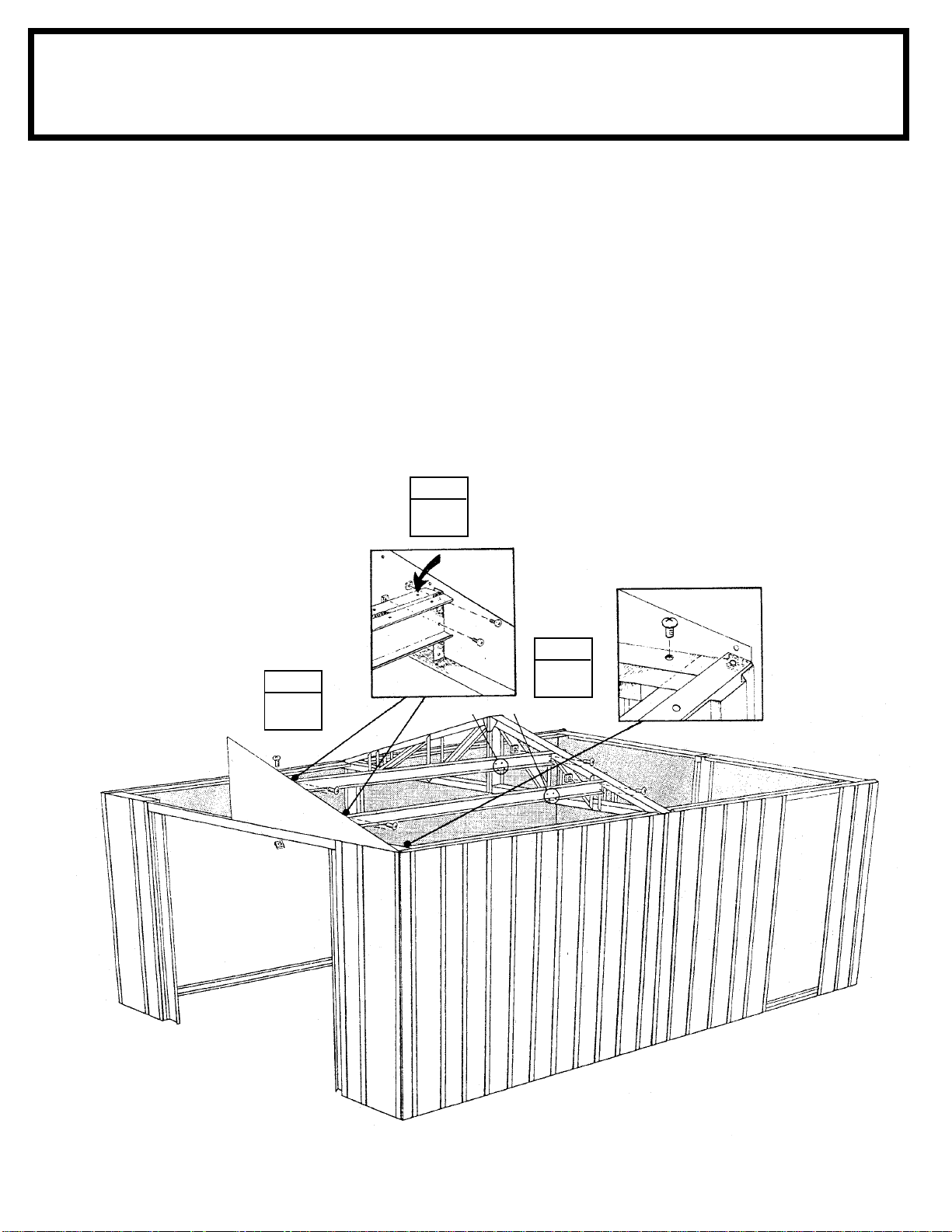
1Lift and fasten a right gable assem-
11
bly at top of lintel using bolts and
nuts.
22
2Spread the 2 halves of a roof beam
22
assembly and fasten the roof beam to
the outer gable bracket using 2 bolts
and nuts.
Hint:Hint:
Hint: The holes along the length of
Hint:Hint:
the beam must be on the top surface
and 4 hole cluster must be fastened
toward truss.
33
3Fasten the outer end of the roof
33
beam to the outer truss bracket of the
truss using 2 bolts and nuts.
● Parts Needed For ●
Gable/Roof BeamsGable/Roof Beams
Gable/Roof Beams
Gable/Roof BeamsGable/Roof Beams
STEP
22
2
22
2" 5cm
●●
Right Gable Assembly (1) Right Gable Assembly (1)
●
Right Gable Assembly (1)
●●
Right Gable Assembly (1) Right Gable Assembly (1)
●●
Roof Beam Assembly (2) Roof Beam Assembly (2)
●
Roof Beam Assembly (2)
●●
Roof Beam Assembly (2) Roof Beam Assembly (2)
Repeat Steps 2 through 3 for the next
roof beam assembly.
STEP
11
1
11
STEP
4 holes toward truss
33
3
33
29
Page 30
Step 14Step 14
Step 14
Step 14Step 14
BX30
11
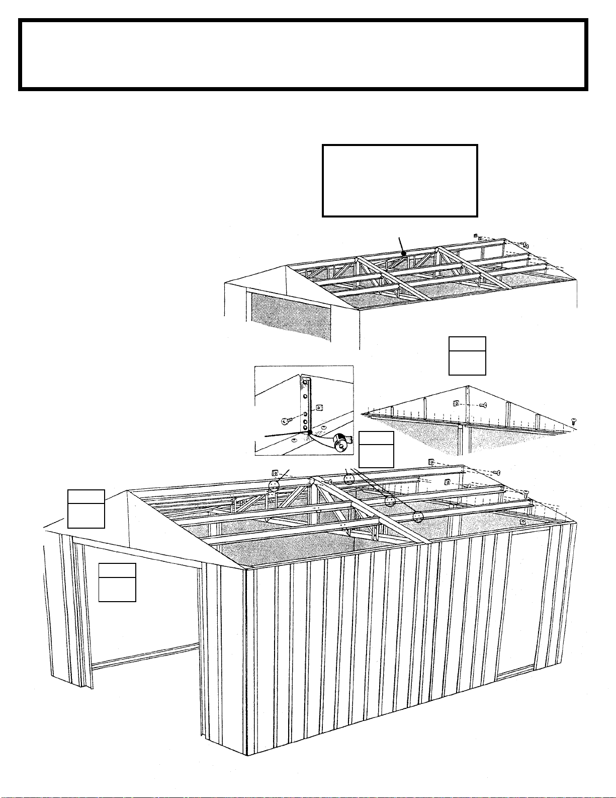
1Lift and fasten a left gable assem-
11
bly in the same manner.
22
2Join the left and right gables to-
22
gether using a bolt and nut in the
third hole from the bottom
only.
● Parts Needed For ●
Gables/Roof BeamsGables/Roof Beams
Gables/Roof Beams
Gables/Roof BeamsGables/Roof Beams
On the 1431, attach the roof
beams between the truss
assemblies as before
NOTENOTE
NOTE
NOTENOTE
●●
Roof Beam Assembly (8) Roof Beam Assembly (8)
●
Roof Beam Assembly (8)
●●
Roof Beam Assembly (8) Roof Beam Assembly (8)
●●
Left Gable Assembly (2) Left Gable Assembly (2)
●
Left Gable Assembly (2)
●●
Left Gable Assembly (2) Left Gable Assembly (2)
●●
Right Gable Assembly (1) Right Gable Assembly (1)
●
Right Gable Assembly (1)
●●
Right Gable Assembly (1) Right Gable Assembly (1)
●●
9462 Roof Beam Assembly (5 14x31) 9462 Roof Beam Assembly (5 14x31)
●
9462 Roof Beam Assembly (5 14x31)
●●
9462 Roof Beam Assembly (5 14x31) 9462 Roof Beam Assembly (5 14x31)
33
3Apply the
33
along the mating edge of the left and
right gables as shown. Cut the
weather stripping to length.
44
4Install roof beam assemblies to
44
the left side of building in the same
manner. Slide a roof beam assembly over center gable flange and
other end over shear plates on truss
and fasten as before.
Repeat roof beam procedure for the
opposite end of building. Note that 4
hole cluster in roof beam assembly,
must be fastened toward truss.
weather strippingweather stripping
weather stripping
weather strippingweather stripping
STEP
44
4
44
Weather
Stripping
Tape
4 holes toward truss
STEP
33
3
33
9462
STEP
22
2
22
(1431)
30
STEP
11
1
11
(1421)
Page 31
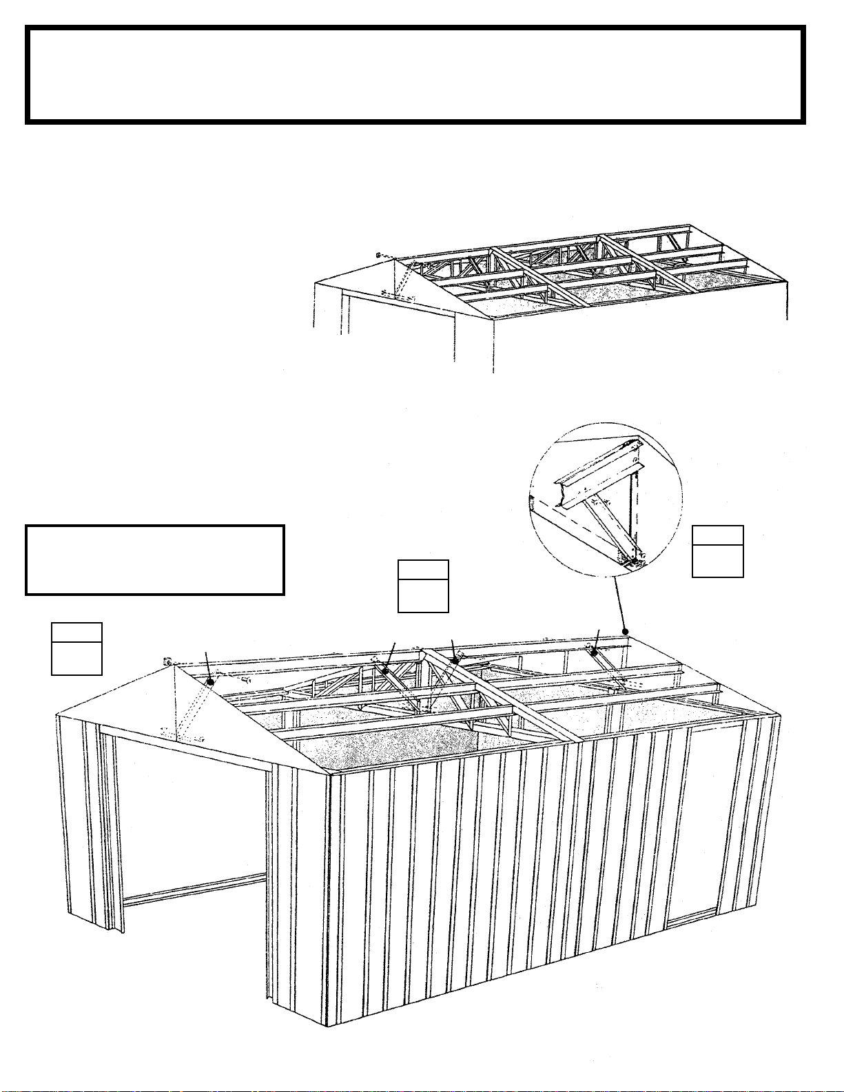
Step 15Step 15
Step 15
Step 15Step 15
BX31
● Parts Needed For ●
GaGa
bb
Ga
GaGa
le-Tle-T
b
le-T
bb
le-Tle-T
rr
uss Struss Str
r
uss Str
rr
uss Struss Str
utut
ut
utut
●●
6954 Gable-Truss Strut 6954 Gable-Truss Strut
●
6954 Gable-Truss Strut
●●
6954 Gable-Truss Strut 6954 Gable-Truss Strut
(4 14x21) (2 14x31) (4 14x21) (2 14x31)
(4 14x21) (2 14x31)
(4 14x21) (2 14x31) (4 14x21) (2 14x31)
11
1Fasten a
11
middle roof beam behind the front
gable by placing tab on the end of the
strut
between
the tab with the holes and fasten the
strut with 2 bolts and nuts.
22
2Fasten the lower end of the strut to
22
the center gable flange with 2 bolts.
Repeat Steps 1 and 2 for the oppo-
site end of building.
33
3At the truss assembly the gable
33
struts are attached between the
middle roof beam and the vertical
brace.
Do not tighten bolts and nuts until
STEP
gable-truss strutgable-truss strut
gable-truss strut to the
gable-truss strutgable-truss strut
the roof beams. Align
NOTENOTE
NOTE
NOTENOTE
all Struts are assembled
6954
11
1
11
6954
STEP
33
3
33
6954
6954
(1431)
STEP
22
2
22
(1421)
31
Page 32
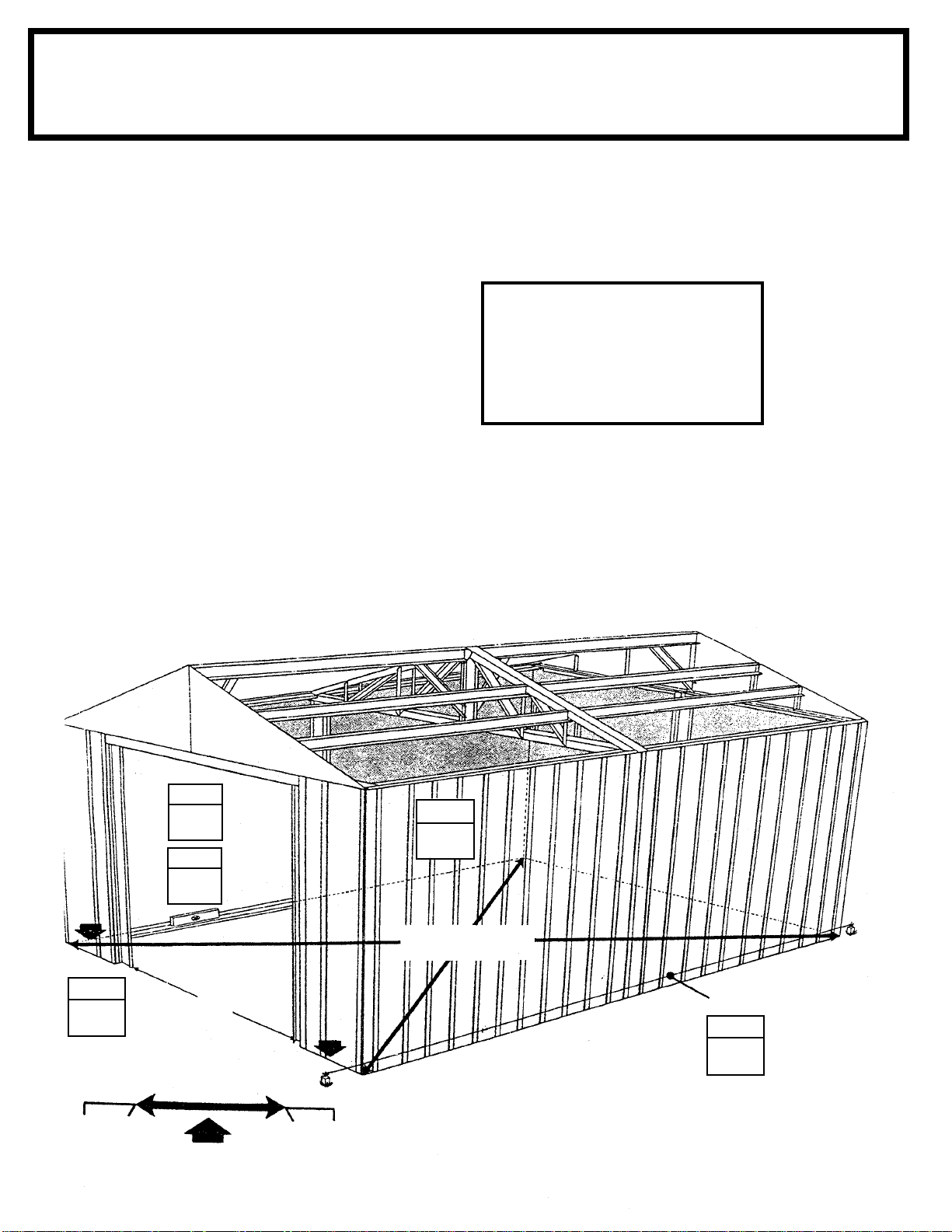
Step 16Step 16
Step 16
Step 16Step 16
BX32
11
1Square the building on the founda-
11
tion and at the top, by measuring
diagonally from corner to corner as
previously done.
22
2Use string to check and see if the
22
sides and rear of building are straight,
not bowed inward or outward.
33
3Level the full perimeter of the floor
33
frame. Shim under with wood shingles if necessary.
44
4Square the front of building as pre-
44
viously done for base.
Squaring the BuildingSquaring the Building
Squaring the Building
Squaring the BuildingSquaring the Building
NOTENOTE
NOTE
NOTENOTE
The 107" (2,72m) door opening
must be held for proper door
alignment. Measure between
the left and right track support.
55
5Anchor front frame to concrete with
55
1/4" diameter expandable anchor
bolts or other means, where shown.
STEP
44
4
44
STEP
33
3
33
STEP
55
5
55
107"
2,72m
STEP
11
1
11
Measure Diagonally
For Squareness
Use String To Straighten
Side Before Anchoring
STEP
32
Left Track
Support
107"
2,72m
Right Track
Support
22
2
22
Page 33
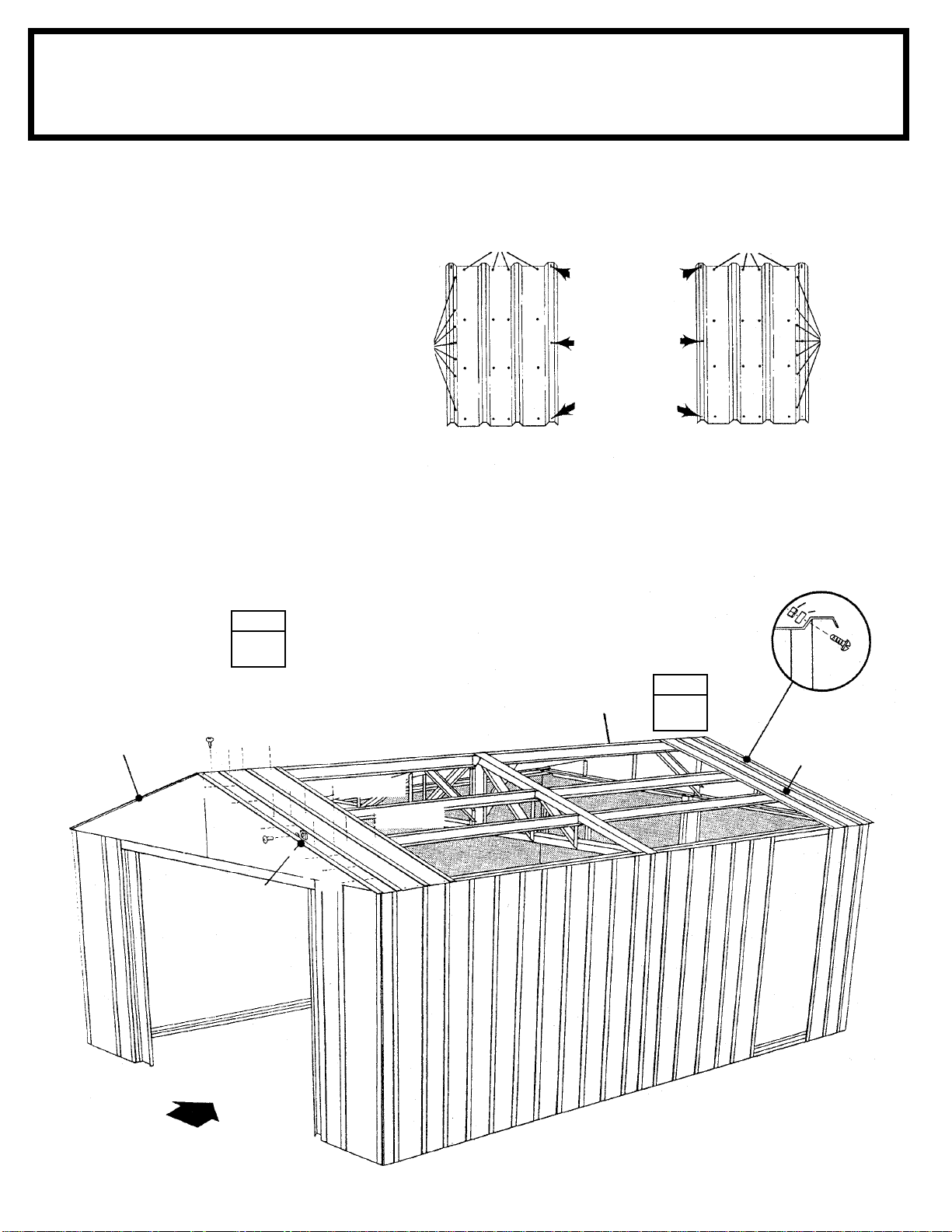
Step 17Step 17
Step 17
Step 17Step 17
BX33
Installing the roof panels is best done
with an 8' step ladder. Each screw
and bolt in the roof requires a washer.
11
1Position
11
at the front corners and fasten to the
gable and roof beams using screws
and bolts as shown.
right and left roof panelsright and left roof panels
right and left roof panels
right and left roof panelsright and left roof panels
Do not fasten
Left/Right Roof PanelsLeft/Right Roof Panels
Left/Right Roof Panels
Left/Right Roof PanelsLeft/Right Roof Panels
the lower end of the panels to the side
eave channel at this time.
Hint:Hint:
Hint: Follow the fastener sequence
Hint:Hint:
shown, for proper alignment.
● Parts Needed For ●
LEFT ROOF PANELLEFT ROOF PANEL
LEFT ROOF PANEL
LEFT ROOF PANELLEFT ROOF PANEL
SCREWS TO ROOF BEAM SCREWS TO ROOF BEAM
FASTEN
TO GABLE
SLOTTED HOLES
AT TOP
FASTEN AT
OVERLAP
SMALL HOLES
AT BOTTOM
●●
9492 Right Roof Panel (2) 9492 Right Roof Panel (2)
●
9492 Right Roof Panel (2)
●●
9492 Right Roof Panel (2) 9492 Right Roof Panel (2)
●●
9493 Left Roof Panel (2) 9493 Left Roof Panel (2)
●
9493 Left Roof Panel (2)
●●
9493 Left Roof Panel (2) 9493 Left Roof Panel (2)
RIGHT ROOF PANELRIGHT ROOF PANEL
RIGHT ROOF PANEL
RIGHT ROOF PANELRIGHT ROOF PANEL
FASTEN
TO GABLE
22
2Install the
22
elsels
els for the rear corners in the position
elsels
shown.
right right
right and
right right
9492
left roof pan- left roof pan-
left roof pan-
left roof pan- left roof pan-
STEP
11
1
11
1
2
3
4
9493
8 thru 11
5
6
12 thru 15
16 thru 19
7
9493
STEP
22
2
22
Nut
Gable
9492
Washer
Bolt
FRONTFRONT
FRONT
FRONTFRONT
33
Page 34
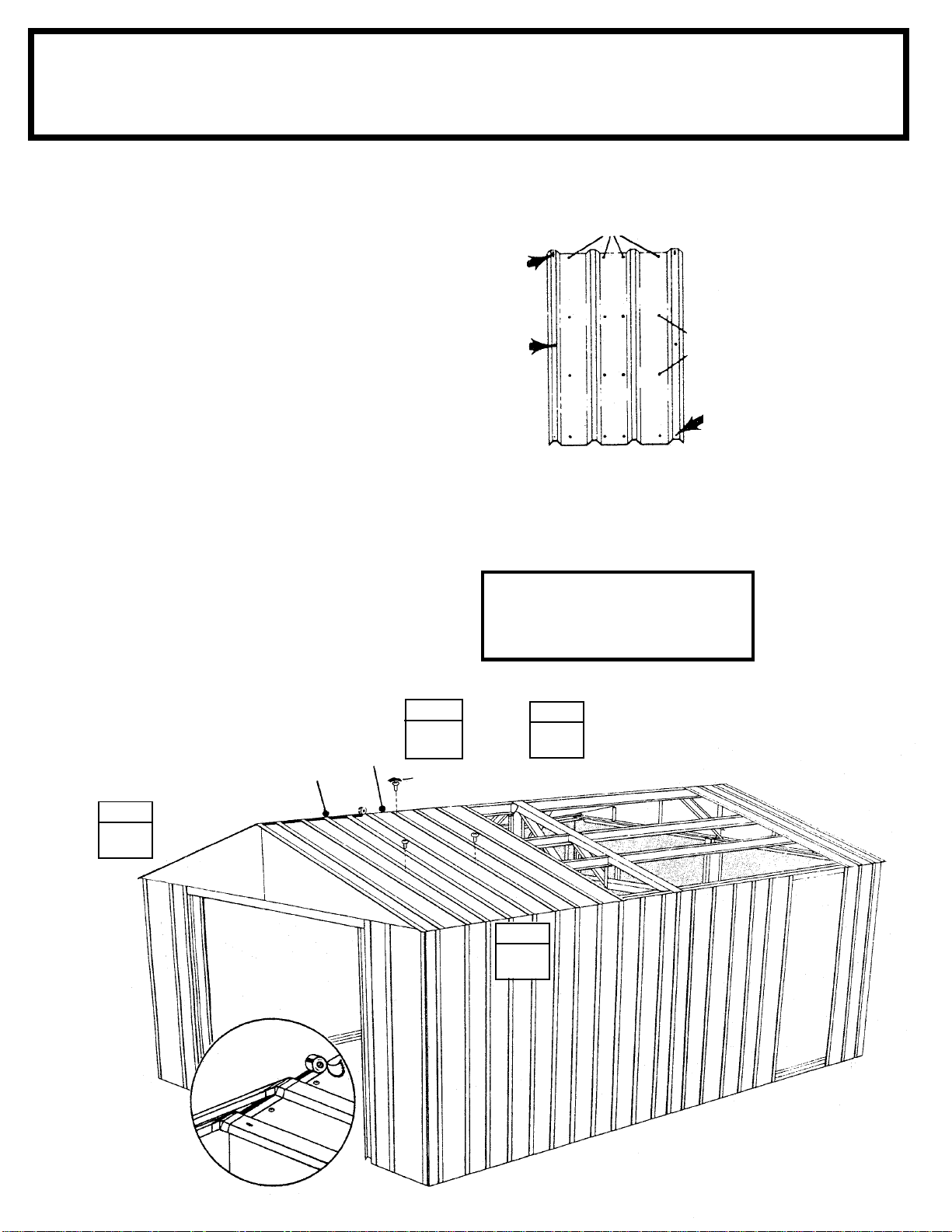
Step 18Step 18
Step 18
Step 18Step 18
BX34
● Parts Needed For ●
Roof PanelsRoof Panels
Roof Panels
Roof PanelsRoof Panels
●●
9491 Roof Panel (4) 9491 Roof Panel (4)
●
9491 Roof Panel (4)
●●
9491 Roof Panel (4) 9491 Roof Panel (4)
11
1Position a
11
rib of left corner roof panel. Fasten
overlap at center of roof panel rib
using a bolt and nut. Fasten to roof
beams as done before using screws.
22
2Install a
22
of building. Repeat procedure with 2
more
side. At the top beam end of panels,
fasten 2nd roof panel rib overlaps
with a bolt and nut.
33
3Cut the
33
into 6 strips, each strip about 2" (5cm)
long. Press 2 strips over the bolt
heads on overlaps at the top of panels. Save the other 4 strips for the rest
of roof.
44
4Cover the join at the peak with
44
weather stripping tape. Unroll the
tape and press it down over the opening at the ridge as you install each
roof panel. Do not cut the tape at this
time.
roof panelsroof panels
roof panels working side to
roof panelsroof panels
roof panel roof panel
roof panel overlapping
roof panel roof panel
roof panel roof panel
roof panel on the left side
roof panel roof panel
weather stripping tapeweather stripping tape
weather stripping tape
weather stripping tapeweather stripping tape
Crimped Rib is Always Overlapped
by Wide Rib of Adjacent Panel
SLOTTED
HOLES AT
FASTEN
OVERLAP
Follow Fastener Sequence
STEP
44
4
9491
44
Weather Stripping Tape
ROOF PANELROOF PANEL
ROOF PANEL
ROOF PANELROOF PANEL
SCREWS TO ROOF BEAM
TOP
AT
FIRST
NOTENOTE
NOTE
NOTENOTE
On the 1431, cut the weather
stripping tape into 10 strips.
STEP
33
3
33
SCREWS TO
ROOF BEAM
SMALL
HOLES
AT BOTTOM
34
STEP
22
2
22
Weather
Stripping
Tape
STEP
11
1
11
Page 35
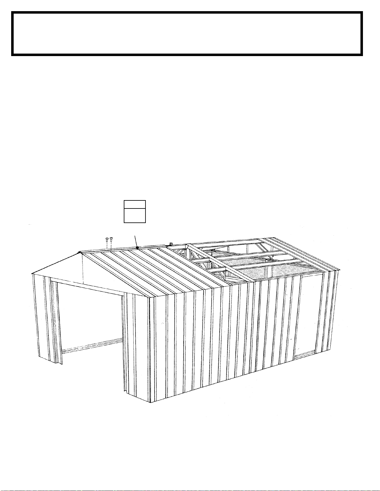
Step 19Step 19
Step 19
Step 19Step 19
BX35
● Parts Needed For ●
Ridge CapRidge Cap
Ridge Cap
Ridge CapRidge Cap
●●
9509 Ridge Cap (1) 9509 Ridge Cap (1)
●
9509 Ridge Cap (1)
●●
9509 Ridge Cap (1) 9509 Ridge Cap (1)
11
1Install a
11
pleted roof section using bolts and
nuts. Do not fasten the ends of the
ridge cap at this time.
ridge capridge cap
ridge cap on the com-
ridge capridge cap
STEP
11
1
11
9509
35
Page 36
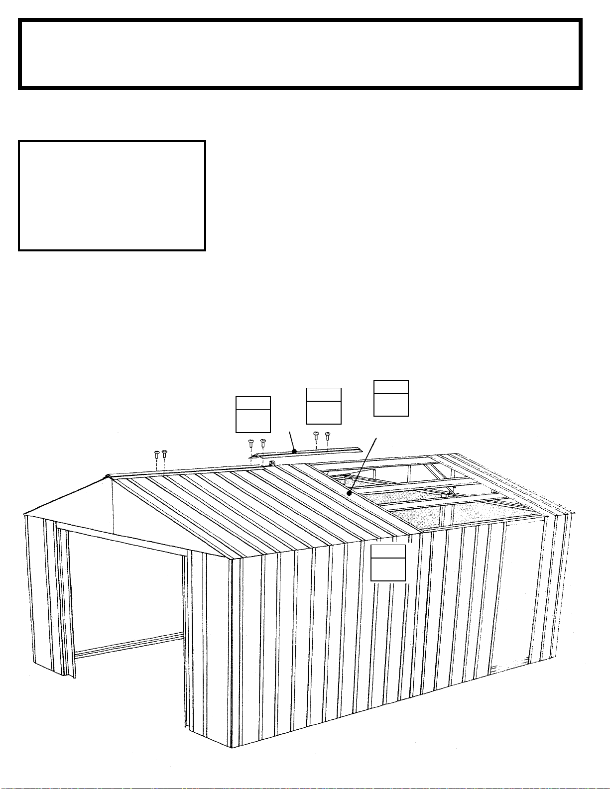
Step 20Step 20
Step 20
Step 20Step 20
BX36
● Parts Needed For ●
Roof Panels & Ridge CapRoof Panels & Ridge Cap
Roof Panels & Ridge Cap
Roof Panels & Ridge CapRoof Panels & Ridge Cap
●●
9509 Ridge Cap (1) 9509 Ridge Cap (1)
●
9509 Ridge Cap (1)
●●
9509 Ridge Cap (1) 9509 Ridge Cap (1)
●●
9491 Roof Panel (6) 9491 Roof Panel (6)
●
9491 Roof Panel (6)
●●
9491 Roof Panel (6) 9491 Roof Panel (6)
11
1Install 4
11
to side.
If roof beam holes do not line up
with the roof panel holes, shift the
building from left to right. If this
does not help, your building may
not be level. Shim the corners
22
2Unroll the weather stripping tape,
22
press it down firmly, but do not cut.
33
3Install the second
33
lapping the first ridge cap. Align the
holes and fasten using bolts.
44
4Install 2 more
44
5th top overlap and cover with
weather strip over head of bolt.
roof panelsroof panels
roof panels working side
roof panelsroof panels
NOTENOTE
NOTE
NOTENOTE
until holes line up.
ridge capridge cap
ridge cap over-
ridge capridge cap
roof panelsroof panels
roof panels. Fasten
roof panelsroof panels
STEP
22
2
22
9509
STEP
33
3
33
STEP
44
4
44
9491
36
STEP
11
1
11
Page 37
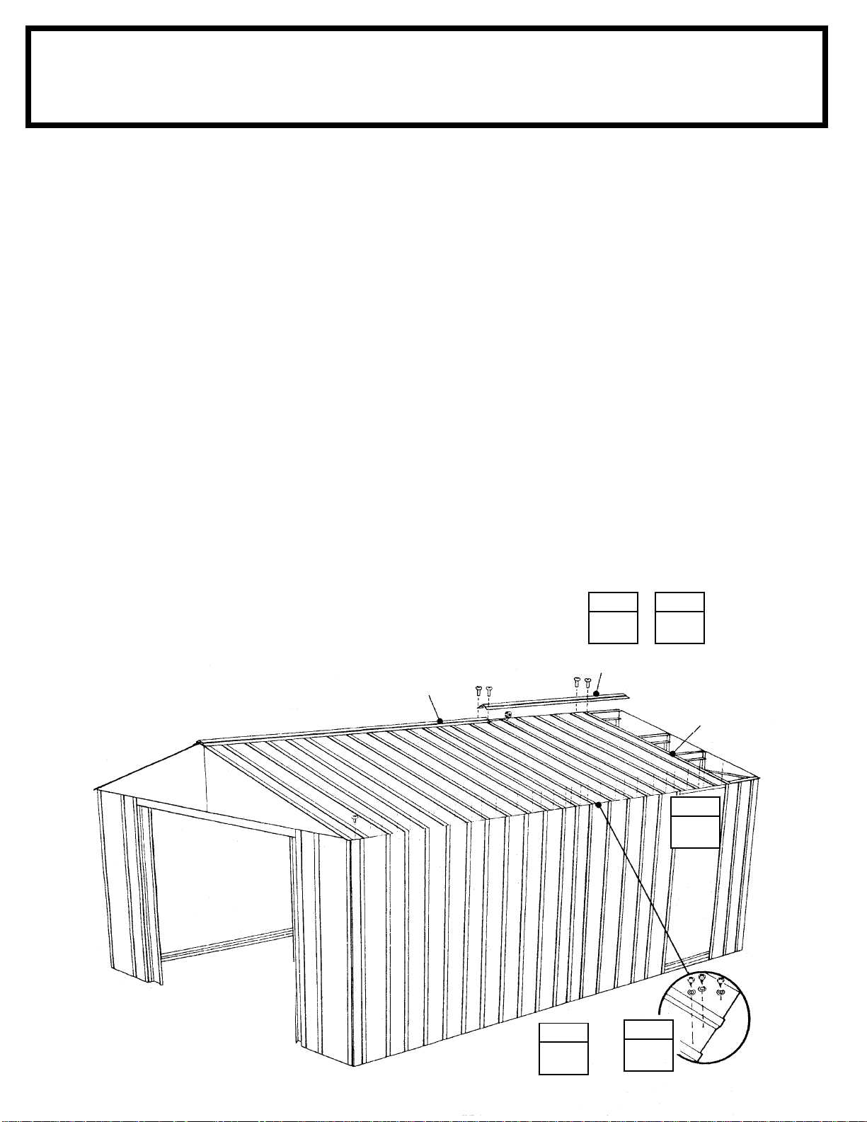
Step 21Step 21
Step 21
Step 21Step 21
BX37
● Parts Needed For ●
Roof Panels/Ridge CapsRoof Panels/Ridge Caps
Roof Panels/Ridge Caps
Roof Panels/Ridge CapsRoof Panels/Ridge Caps
●●
9509 Ridge Cap (1) 9509 Ridge Cap (1)
●
9509 Ridge Cap (1)
●●
9509 Ridge Cap (1) 9509 Ridge Cap (1)
●●
9512 Ridge Cap (1 1431) 9512 Ridge Cap (1 1431)
●
9512 Ridge Cap (1 1431)
●●
9512 Ridge Cap (1 1431) 9512 Ridge Cap (1 1431)
●●
9491 Roof Panel (4 14x21) (12 14x31) 9491 Roof Panel (4 14x21) (12 14x31)
●
9491 Roof Panel (4 14x21) (12 14x31)
●●
9491 Roof Panel (4 14x21) (12 14x31) 9491 Roof Panel (4 14x21) (12 14x31)
11
1Install 2 more
11
22
2Install the third
22
ping the second ridge cap as before.
Temporarily remove the rear corner
roof panels, and install the remaining
roof panelsroof panels
2
roof panels. Fasten 7th top over-
roof panelsroof panels
lap and cover with weather strip over
head of bolt.
33
3Install the corner roof panels. Fas-
33
ten ridge cap using bolts and nuts.
44
4Fasten the lower end of the panels
44
to the side eave channels using
screws and black washers.
roof panelsroof panels
roof panels.
roof panelsroof panels
ridge capridge cap
ridge cap overlap-
ridge capridge cap
11
1On the 1431 install 2 more
11
panelspanels
panels.
panelspanels
22
2Install the third
22
ping the second ridge cap as before.
Install 6 more
tening 8th and 9th top overlap and
cover with weather strip over head of
bolt. Fasten ridge cap using bolts
and nuts.
33
3Install 2
33
ridge capridge cap
ridge cap. Temporarily remove the
ridge capridge cap
rear corner roof panels, and install
the remaining 2
11th top overlap and cover with
weather strip over head of bolt.
44
4Install the corner roof panels. Fas-
44
ten ridge cap using bolts and nuts.
55
5Fasten the lower end of the panels
55
to the side eave channels using
screws and black washers.
roof panelsroof panels
roof panels, and the fourth
roof panelsroof panels
ridge capridge cap
ridge cap overlap-
ridge capridge cap
roof panelsroof panels
roof panels, while fas-
roof panelsroof panels
roof panelsroof panels
roof panels. Fasten
roof panelsroof panels
roofroof
roof
roofroof
STEP
STEP
9512 (1431)
STEP
44
4
44
9509
22
2
22
STEP
33
3
33
Cut
Weather Stripping
and Fold Under
STEP
55
5
55
11
1
11
9491
37
Page 38
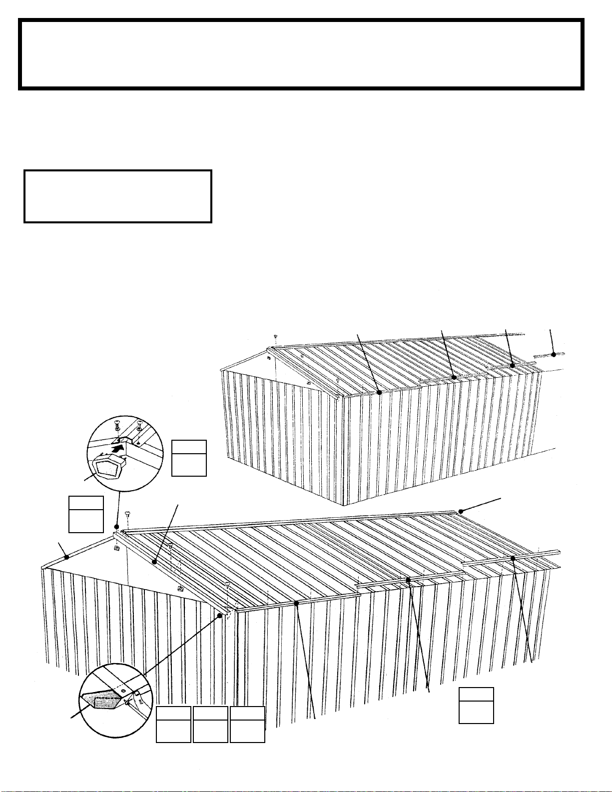
Step 22Step 22
Step 22
Step 22Step 22
BX38
● Parts Needed For ●
Roof Roof
Roof
Roof Roof
TT
T
TT
rr
r
rr
imim
im
imim
●●
7023 Left Roof trim (2) 7023 Left Roof trim (2)
●
7023 Left Roof trim (2)
●●
7023 Left Roof trim (2) 7023 Left Roof trim (2)
●●
7024 Right Roof Trim (2) 7024 Right Roof Trim (2)
●
7024 Right Roof Trim (2)
●●
7024 Right Roof Trim (2) 7024 Right Roof Trim (2)
●●
9510 Side Roof Trim (6) 9510 Side Roof Trim (6)
●
9510 Side Roof Trim (6)
●●
9510 Side Roof Trim (6) 9510 Side Roof Trim (6)
●●
9513 Side Roof Trim (2 1431) 9513 Side Roof Trim (2 1431)
●
9513 Side Roof Trim (2 1431)
●●
9513 Side Roof Trim (2 1431) 9513 Side Roof Trim (2 1431)
11
1Attach the
11
lower end of the roof panels on each
side of the building using screws at
each panel overlap.
A single screw fastens both trim
pieces at the overlap.
22
2Position
22
the ends of roof, noting that trim slips
under ridge cap, but fits on top of side
roof trim.
33
3Fasten roof panel rib, trim,
33
cap cap
cap and ridge cap together using
cap cap
bolts and nuts. Fasten the remaining
peak cap in the same manner.
side roof trimside roof trim
side roof trim to the
side roof trimside roof trim
NOTENOTE
NOTE
NOTENOTE
left left
left and
left left
right roof trimright roof trim
right roof trim to
right roof trimright roof trim
peakpeak
peak
peakpeak
44
4Using your thumb and index finger,
44
overbend the bottom flange of the
side roof trim at the corner inward
enough so the right and left roof trim
caps fit onto right and left corners.
55
5Fasten trim to side trim using a
55
screw and washer into roof panel.
66
6Fasten the roof trim caps to the side
66
trim using a screw.
9510
9513
9510
9510
Peak Cap
STEP
7023
Roof
Trim
Cap
STEP
33
3
33
Arrow Logo
7024
22
2
22
STEP
STEP
44
4
44
STEP
55
5
55
66
6
66
9510
(1431)
9510
(1421)
STEP
11
1
11
Goes on Front
of Building
9510
38
Page 39
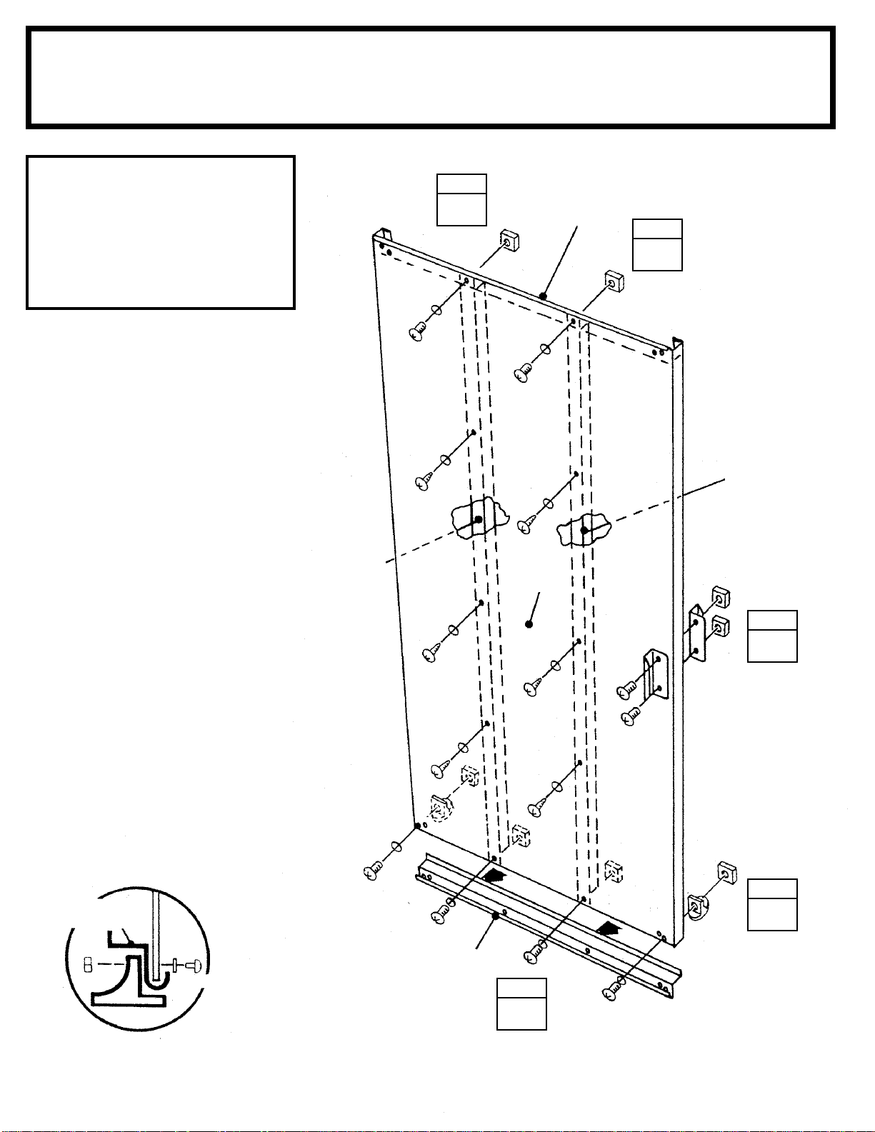
Step 23Step 23
Step 23
Step 23Step 23
BX39
NOTENOTE
NOTE
NOTENOTE
To assemble door to slide from
left to right (opening), position
door with handle holes on left
side of door. Position handle
holes on right side if door is to
slide from right to left (opening).
Each bolt and screw in the door requires a washer.
● Parts Needed For ●
Side Door Side Door
Side Door
Side Door Side Door
AssembAssemb
Assemb
AssembAssemb
STEP
22
2
22
●●
9498 Door (1) 9498 Door (1)
●
9498 Door (1)
●●
9498 Door (1) 9498 Door (1)
●●
9499 Horizontal Door Brace (2) 9499 Horizontal Door Brace (2)
●
9499 Horizontal Door Brace (2)
●●
9499 Horizontal Door Brace (2) 9499 Horizontal Door Brace (2)
●●
9500 Vertical Door Brace (2) 9500 Vertical Door Brace (2)
●
9500 Vertical Door Brace (2)
●●
ll
yy
l
y
ll
yy
9499
9500 Vertical Door Brace (2) 9500 Vertical Door Brace (2)
STEP
11
1
11
11
1Hold the
11
against the inside surface of
align holes, and fasten with 3 screws.
22
2Repeat Step 1 for remaining verti-
22
cal door brace.
33
3Attach the
33
bolts and nuts, as shown.
44
4Put a
44
the top edge and bottom edge and
fasten
55
5Attach the
55
shown.
with 2 bolts and nuts on each
vertical door bracevertical door brace
vertical door brace
vertical door bracevertical door brace
doordoor
door,
doordoor
handlehandle
handle to the door with 2
handlehandle
horizontal door bracehorizontal door brace
horizontal door brace onto
horizontal door bracehorizontal door brace
lower door guideslower door guides
lower door guides as
lower door guideslower door guides
9500
9500
9498
STEP
33
3
33
.
END VIEW
SHOWING:
Horizontal
Door Brace
Guide
Door
Washer
9499
STEP
44
4
44
STEP
55
5
55
39
Page 40
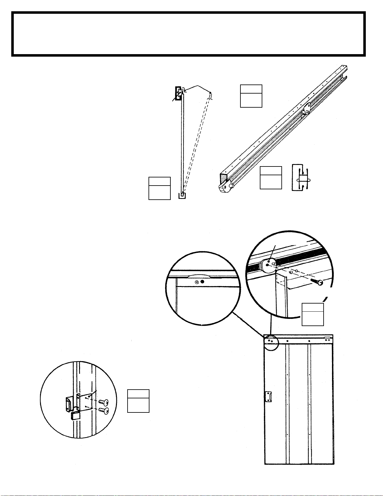
Step 24Step 24
Step 24
Step 24Step 24
BX40
● Parts Needed For ●
Door InstallationDoor Installation
Door Installation
Door InstallationDoor Installation
Door Assembly (1)Door Assembly (1)
Door Assembly (1)
Door Assembly (1)Door Assembly (1)
●●
7972 Door Handle Lock Bracket (1) 7972 Door Handle Lock Bracket (1)
●
7972 Door Handle Lock Bracket (1)
●●
7972 Door Handle Lock Bracket (1) 7972 Door Handle Lock Bracket (1)
11
1Position
11
from the end of door track, as shown
in the end view.
22
2From inside the building, put the
22
bottom of the door behind door jamb
into the lower door track.
33
3Position the top of the door so that
33
the holes in the door line up with the
holes in the door slides.
44
4Fasten the door to the door slides
44
using a #10Bx1/2" screws.
55
5Position
55
aligned with handle holes, against
door jamb. Using a pencil mark
through holes onto jamb, remove
bracket and drill (2) 1/4" diameter
holes in jamb. Fasten bracket to door
jamb using 2 bolts and nuts.
door slides door slides
door slides onto the legs,
door slides door slides
door handle lock bracketdoor handle lock bracket
door handle lock bracket
door handle lock bracketdoor handle lock bracket
Track
Door Slide
STEP
22
2
22
Lower Door Track
Horizontal Door Brace
STEP
33
3
33
STEP
11
1
11
Door Slide
END VIEW
OF TRACK
#10Bx1/2" Screw
40
Door
Jamb
7972
STEP
55
5
55
Door
STEP
44
4
44
Page 41
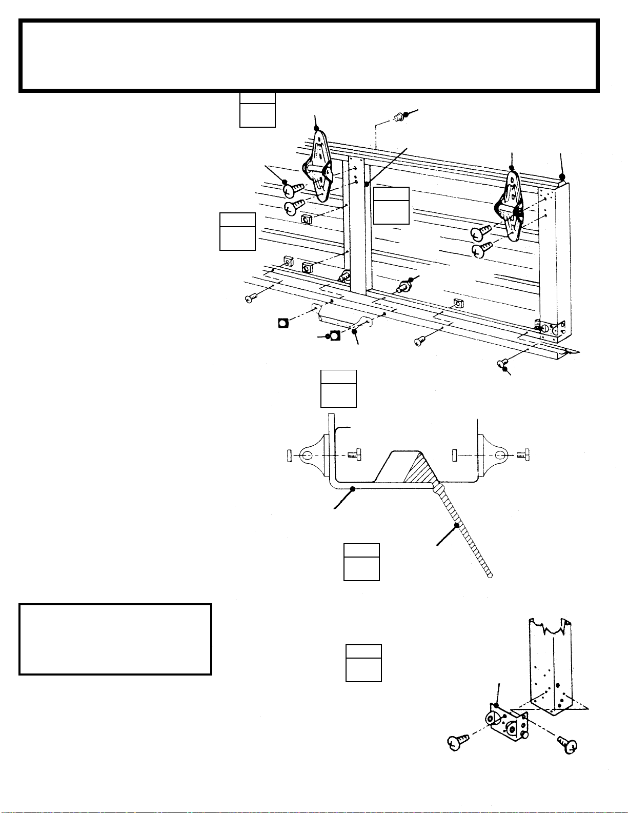
Step 25Step 25
Step 25
Step 25Step 25
BX41
● Parts Needed For ●
Roll-Up-DoorRoll-Up-Door
Roll-Up-Door
Roll-Up-DoorRoll-Up-Door
●●
Door Panels (4) Door Panels (4)
●
Door Panels (4)
●●
Door Panels (4) Door Panels (4)
●●
9479 Bottom Angle (1) 9479 Bottom Angle (1)
●
9479 Bottom Angle (1)
●●
9479 Bottom Angle (1) 9479 Bottom Angle (1)
●●
9504 Weather Strip (1) 9504 Weather Strip (1)
●
9504 Weather Strip (1)
●●
9504 Weather Strip (1) 9504 Weather Strip (1)
11
1Layout the
11
surface, protecting the panels from
being scratched.
22
2Bolt the middle stiles at the center
22
of the 4 door panels where indicated
with #10-32x3/8" bolts on the outside
and square nuts inside.
33
3On the
33
tion, tion,
tion, attach the
tion, tion,
et et
et to the lower right corner and the
et et
bottom bracket bottom bracket
bottom bracket to the left side using
bottom bracket bottom bracket
#10Bx1/2" truss head screws into
end stiles.
44
4Loosely install
44
bottom section using #10-32x3/8"
bolts and square nuts. Insert vinyl
weather strip weather strip
weather strip between angle and
weather strip weather strip
bottom section and tighten bolts.
door panels door panels
door panels on a flat
door panels door panels
door panel bottom sec-door panel bottom sec-
door panel bottom sec-
door panel bottom sec-door panel bottom sec-
right bottom brack-right bottom brack-
right bottom brack-
right bottom brack-right bottom brack-
leftleft
left
leftleft
bottom angle bottom angle
bottom angle to the
bottom angle bottom angle
STEP
66
6
66
#10Bx1/2"
Truss Head Screw
STEP
11
1
11
1/4-20 Square Nut
#1 Hinge
Lift Handle
STEP
55
5
55
STEP
22
2
22
#10-32x3/8"
Bolt & Square Nut
MIDDLE
STILE
9508
1/4-20x1/2" Hex
Head Bolt
Raised
Rib On
#1 Hinge
#10-32x3/8" Bolt
Top
55
5Fasten 2
55
tion, just below the bottom of middle
stile using 1/4-20x1/2" hex head bolts
and 1/4-20 square nuts.
66
6Install the
66
corners and to the middle stile of the
bottom section using #10Bx1/2" truss
head screws.
Be sure you fasten the lower part
of hinge to the top of each stile.
The top hinge leaf is marked.
lift handles lift handles
lift handles to bottom sec-
lift handles lift handles
#1 hinges #1 hinges
#1 hinges at the upper
#1 hinges #1 hinges
NOTENOTE
NOTE
NOTENOTE
9479
STEP
44
4
44
STEP
33
3
33
9504
BOTTOM SECTION
END STILE (RH)
(LH) Bottom Bracket
(RH) Bottom Bracket
(Shown)
#10Bx1/2"
Truss Head Screw
41
Page 42
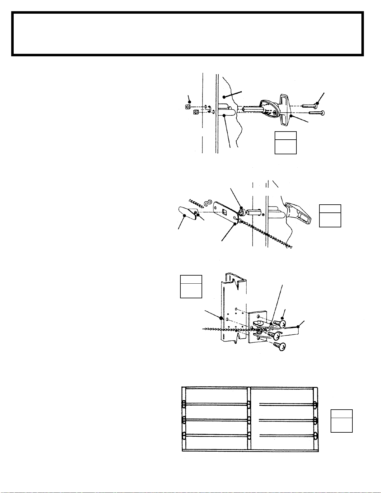
Step 26Step 26
Step 26
Step 26Step 26
BX42
11
1With the key, unlock the outside
11
locking handle locking handle
locking handle and rotate the han-
locking handle locking handle
dle to a vertical position. Insert the
square shank through the hole located in the center of
section. section.
section. Slide in the
section. section.
and insert the #10-32x2 1/2" flat head
bolts through handle, spacer and stile.
Secure with square nuts and tighten.
22
2Turn the locking handle to a hori-
22
zontal position. Slide the
bar spacer bar spacer
bar spacer over the square shank of
bar spacer bar spacer
the lock handle and slip the
bar bar
bar over shank. Secure with the
bar bar
side "T" handle. side "T" handle.
side "T" handle. Tighten set screw
side "T" handle. side "T" handle.
in handle. Attach small
holes on the flat latch bar. Slip opposite end of "S" hooks through
chains.chains.
chains.
chains.chains.
door panel lockdoor panel lock
door panel lock
door panel lockdoor panel lock
stile spacersstile spacers
stile spacers
stile spacersstile spacers
inside latchinside latch
inside latch
inside latchinside latch
flat latchflat latch
flat latch
flat latchflat latch
in-in-
in-
in-in-
"S" hooks "S" hooks
"S" hooks to
"S" hooks "S" hooks
latchlatch
latch
latchlatch
● Parts Needed For ●
Roll-Up-DoorRoll-Up-Door
Roll-Up-Door
Roll-Up-DoorRoll-Up-Door
#10-32 Square Nut
MIDDLE STILE
Stile Spacer
Inside Latch
Bar Spacer
"S" Hook
Set Screw
Inside "T" Handle
Flat Latch Bar
●●
9507 Door Panel Lock Section (1) 9507 Door Panel Lock Section (1)
●
9507 Door Panel Lock Section (1)
●●
9507 Door Panel Lock Section (1) 9507 Door Panel Lock Section (1)
9507
STEP
MIDDLE STILE
11
1
11
#10-32 x 2 1/'2"
Flat Head Bolt
Locking Handle
STEP
Latch Chain
22
2
22
33
3Attach the
33
end stiles on the lock section. Attach
"S" hooks to the holes on top of the
latches. Attach the latch chains to the
"S" hooks so that the chain is taut.
Hint: Hint:
Hint: If chain is too tight, latches will
Hint: Hint:
not engage strikes (on track) properly. If chain is too loose, the lock
handle will not retract latches. Adjust
chains by changing the hole location
of "S" hook through chain.
44
4Attach
44
the upper corners of end stiles. Fasten #1 hinge to the middle stile.
Hint: Hint:
Hint: When installing hinges, be sure
Hint: Hint:
the hinge number is always on the
lower hinge leaf.
spring latches spring latches
spring latches to the
spring latches spring latches
#2 hinges #2 hinges
#2 hinges to lock section at
#2 hinges #2 hinges
STEP
33
3
33
CENTER
OF END
STILE
Latch Chain
#3
#2
#1
Bottom Section
"S" Hook
END STILE
Hinge Location Schedule Only!Hinge Location Schedule Only!
Hinge Location Schedule Only!
Hinge Location Schedule Only!Hinge Location Schedule Only!
Do Not Join Panels TogetherDo Not Join Panels Together
Do Not Join Panels Together
Do Not Join Panels TogetherDo Not Join Panels Together
Top Section
#1
Intermediate
#1
Lock Section
#1
9506
9506
9507
9508
10Bx1/2" Truss
Head Screw
Spring Latch
#3
#2
#1
STEP
44
4
44
42
Page 43
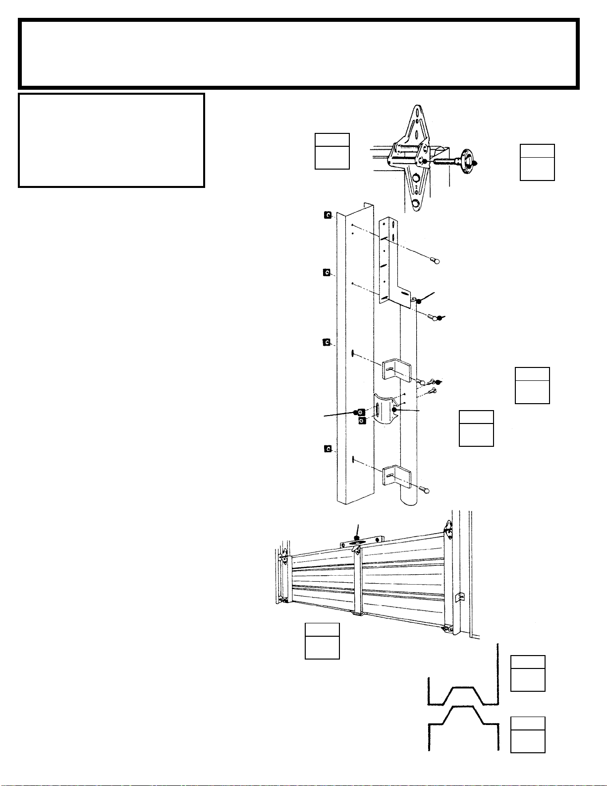
Step 27Step 27
Step 27
Step 27Step 27
BX43
NOTENOTE
NOTE
NOTENOTE
When rib neck bolts are inserted
in the track, use bolts with heads
located on the inner side of the
track to prevent interference with
the movement of the rollers.
11
1Repeat procedure for the third
11
panelpanel
panel using
panelpanel
and #1 hinge at middle stile.
#3 hinges#3 hinges
#3 hinges at end stiles
#3 hinges#3 hinges
doordoor
door
doordoor
● Parts Needed For ●
Roll-Up-DoorRoll-Up-Door
Roll-Up-Door
Roll-Up-DoorRoll-Up-Door
#2
or #3
STEP
LEFT TRACK
SUPPORT
Hinge
11
1
11
●●
9506 Door Panel (1) 9506 Door Panel (1)
●
9506 Door Panel (1)
●●
9506 Door Panel (1) 9506 Door Panel (1)
●●
9507 Door Panel Lock section (1) 9507 Door Panel Lock section (1)
●
9507 Door Panel Lock section (1)
●●
9507 Door Panel Lock section (1) 9507 Door Panel Lock section (1)
●●
9508 Door Panel Bottom Section (1) 9508 Door Panel Bottom Section (1)
●
9508 Door Panel Bottom Section (1)
●●
9508 Door Panel Bottom Section (1) 9508 Door Panel Bottom Section (1)
●●
67667 Left Vertical Track (1) 67667 Left Vertical Track (1)
●
67667 Left Vertical Track (1)
●●
67667 Left Vertical Track (1) 67667 Left Vertical Track (1)
●●
67666 Right Vertical Door Track (1) 67666 Right Vertical Door Track (1)
●
67666 Right Vertical Door Track (1)
●●
67666 Right Vertical Door Track (1) 67666 Right Vertical Door Track (1)
STEP
Roller
Insert Roller Shaft
only in barrel hole
shown!
22
2
22
22
2Insert the
22
holes on the hinges furthest out from
the face of the end stiles on all 3
panels. Note that #1 hinge has only
1 barrel. Insert rollers through the
tabs on the bottom brackets on bottom section.
33
3Attach
33
loosely to right and left track supports
using 1/4-20x1/2" hex head bolts and
square nuts.
44
4Attach spring latch
44
to vertical tracks using 1/4-20x1/2"
rib neck bolts and square nuts.
55
5Lift the bottom section and insert
55
the rollers into the vertical tracks. Slide
the panel down and level across top.
Shim to level if necessary.
rollerroller
roller shaft into the barrel
rollerroller
rightright
right and
rightright
left vertical tracksleft vertical tracks
left vertical tracks
left vertical tracksleft vertical tracks
strikers strikers
strikers loosely
strikers strikers
Square Nut
Square Nut
LEVEL
67667
1/4-20x1/2"
Hex Head Bolt
1/4-20x1/2"
Rib Neck Bolt
Striker
Right Vertical
Track 67666
STEP
44
4
44
STEP
33
3
33
66
6Insert lock section into vertical
66
tracks. Attach hinges from #1 to #2
panel by inserting #10Bx1/2" truss
head screws at bottom edge of lock
section.
77
7Position third
77
ten in the same manner. Do not
fasten the last door panel at this time.
door paneldoor panel
door panel and fas-
door paneldoor panel
STEP
55
5
55
Door Panel Lock Section
9508
Door Panel
9506
9507
STEP
77
7
77
STEP
66
6
66
43
Page 44
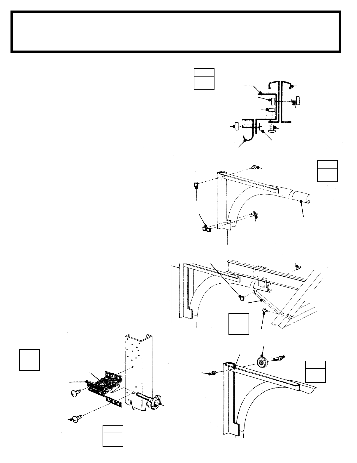
Step 28Step 28
Step 28
Step 28Step 28
BX44
● Parts Needed For ●
Roll-Up-DoorRoll-Up-Door
Roll-Up-Door
Roll-Up-DoorRoll-Up-Door
●●
7817 Spring Support Bracket (2) 7817 Spring Support Bracket (2)
●
7817 Spring Support Bracket (2)
●●
7817 Spring Support Bracket (2) 7817 Spring Support Bracket (2)
●●
67476 Right Horizontal Track (1) 67476 Right Horizontal Track (1)
●
67476 Right Horizontal Track (1)
●●
67476 Right Horizontal Track (1) 67476 Right Horizontal Track (1)
●●
67475 Left Horizontal Track (1) 67475 Left Horizontal Track (1)
●
67475 Left Horizontal Track (1)
●●
67475 Left Horizontal Track (1) 67475 Left Horizontal Track (1)
●●
9511 Truss Strut (2) 9511 Truss Strut (2)
●
9511 Truss Strut (2)
●●
9511 Truss Strut (2) 9511 Truss Strut (2)
●●
9506 Door Panel (1) 9506 Door Panel (1)
●
9506 Door Panel (1)
●●
9506 Door Panel (1) 9506 Door Panel (1)
11
1Install
11
the roof beams using bolts shown.
22
2Attach the
22
track track
track to the right and left vertical track
track track
using bolts and nuts shown.
33
3Fasten
33
on truss assembly using 1/4-20x1/2"
hex head bolt and square nut. Fasten opposite end to spring support
bracket and horizontal track using
1/4-20x1/2" rib neck bolt and square
nut.
44
4Attach the
44
to the 3rd hole on the support angle of
the horizontal track using 3/8 - 16 x
1 1/2" hex head bolt and 3/8-16 hex
nut.
spring support brackets spring support brackets
spring support brackets to
spring support brackets spring support brackets
right right
right and
right right
track struts track struts
track struts to open hole
track struts track struts
sheave sheave
sheave (pulley wheel)
sheave sheave
left horizontalleft horizontal
left horizontal
left horizontalleft horizontal
STEP
11
1
11
1/4-20 Square Nut
1/4-20 Square Nut
7817
1/4-20 Square Nut
#10-32 Square Nut
67476
1/4-20x1/2"
Rib Neck Bolt
#10-32x5/16" Bolt
1/4-20 x 1 1/2"
Hex Head Bolt
1/4-20x1/2"
Hex Head Bolt
ROOF BEAMS
1/4-20x1/2"
Hex Head Bolt
STEP
22
2
22
67475
55
5Position fourth
55
door panel. Fasten top of hinges to
bottom of fourth door panel using
#10Bx1/2" truss head screws.
66
6Engage roller with
66
fixture, fixture,
fixture, slide roller into horizontal
fixture, fixture,
track. Move assembly to line up with
holes in end stile and fasten with
#10Bx1/2" truss head screws.
STEP
55
5
55
Top Fixture
#10Bx1/2"
Truss Head Screw
door panel door panel
door panel on third
door panel door panel
top adjustabletop adjustable
top adjustable
top adjustabletop adjustable
Door Panel (Top)
9506
Adjustment Nut
STEP
END STILE
1/4-20 Square Nut
3/8-16
Hex Nut
Roller
9511
STEP
33
3
33
3rd HOLE
1/4-20x1/2"
Rib Neck Bolt
TRUSS
ASSEMBLY
1/4-20x1/2" Hex Head Bolt
Sheave
& Square Nut
3/8-16 x 1 1/2"
Hex Head Bolt
STEP
44
4
44
44
66
6
66
Page 45
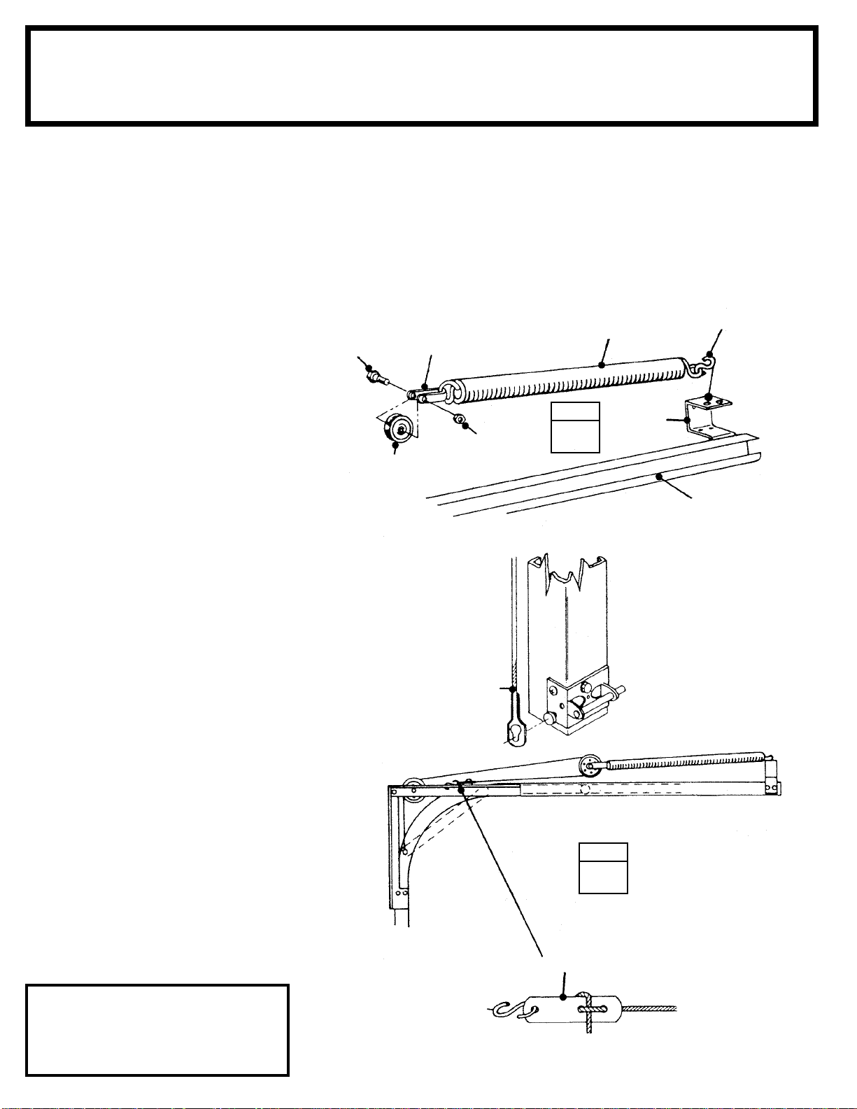
Step 29Step 29
Step 29
Step 29Step 29
BX45
CAUTION:CAUTION:
CAUTION:
CAUTION:CAUTION:
FROM THIS POINT ON, BE SUREFROM THIS POINT ON, BE SURE
FROM THIS POINT ON, BE SURE
FROM THIS POINT ON, BE SUREFROM THIS POINT ON, BE SURE
TO USE EXTREME CAUTIONTO USE EXTREME CAUTION
TO USE EXTREME CAUTION
TO USE EXTREME CAUTIONTO USE EXTREME CAUTION
UNTIL THE DOOR IS PROPERLYUNTIL THE DOOR IS PROPERLY
UNTIL THE DOOR IS PROPERLY
UNTIL THE DOOR IS PROPERLYUNTIL THE DOOR IS PROPERLY
SPRUNG AND OPERATINGSPRUNG AND OPERATING
SPRUNG AND OPERATING
SPRUNG AND OPERATINGSPRUNG AND OPERATING
11
1Attach
11
Fasten
opposite ends of springs using a 3/816x1 1/2" hex head bolt and 3/8 nut.
Attach spring assemblies to spring
support brackets.
22
2Carefully raise the door to a fully
22
open position and prop. Make sure
the door is level in the opening. Slip
the keyed end of the
over the studs of the bottom brackets.
Thread cable over front sheave,
around spring sheave and attach end
to
with "S" hook in a convenient hole in
horizontal track angle, keeping equal
tension on both springs, so that door
hangs level. Once cable is installed,
remove prop and lower door.
"S" hooks "S" hooks
"S" hooks to both
"S" hooks "S" hooks
sheave sheave
sheave and
sheave sheave
cable lacer. cable lacer.
cable lacer. Attach cable lacer
cable lacer. cable lacer.
spring clevis spring clevis
spring clevis to
spring clevis spring clevis
springs.springs.
springs.
springs.springs.
keyed cablekeyed cable
keyed cable
keyed cablekeyed cable
Roll-Up-DoorRoll-Up-Door
Roll-Up-Door
Roll-Up-DoorRoll-Up-Door
CHECKCHECK
CHECK
CHECKCHECK
Be sure that the lift cables do not rub and/or the rollers do not
bind in the track when door is opened or closed. Recheck the
springs to be sure that there is equal tension on both springs. This
is extremely important for proper door operation.
ADJUSTADJUST
ADJUST
ADJUSTADJUST
Springs by changing location of "S" hooks to another hole on
support angle of the horizontal track.
3/8-16 1 1/2"
Hex Head Bolt
Sheave
Spring Clevis
3/8-16
Hex Nut
STEP
11
1
11
Spring
7817
"S" Hook
67476
33
3Adjust vertical tracks so rollers seat
33
in "U" of track and bottom rollers fit
snug against bottom brackets, but
not too tight, so rollers will operate
freely. When complete, tighten all
track bolts.
44
4Adjust striker plates for proper en-
44
gagement with the latches. Adjust
the top adjustable fixture in or out and
tighten the nut and bolt to hold the
fourth door panel against the lintel.
NOTENOTE
NOTE
NOTENOTE
Recheck all door fasteners and
hardware to be sure that each
fastener is tight and secure.
Keyed Cable
(LH) Bottom Bracket
LH ASSEMBLY
STEP
22
2
22
Cable Lacer
Keyed Cable"S" Hook
45
Page 46
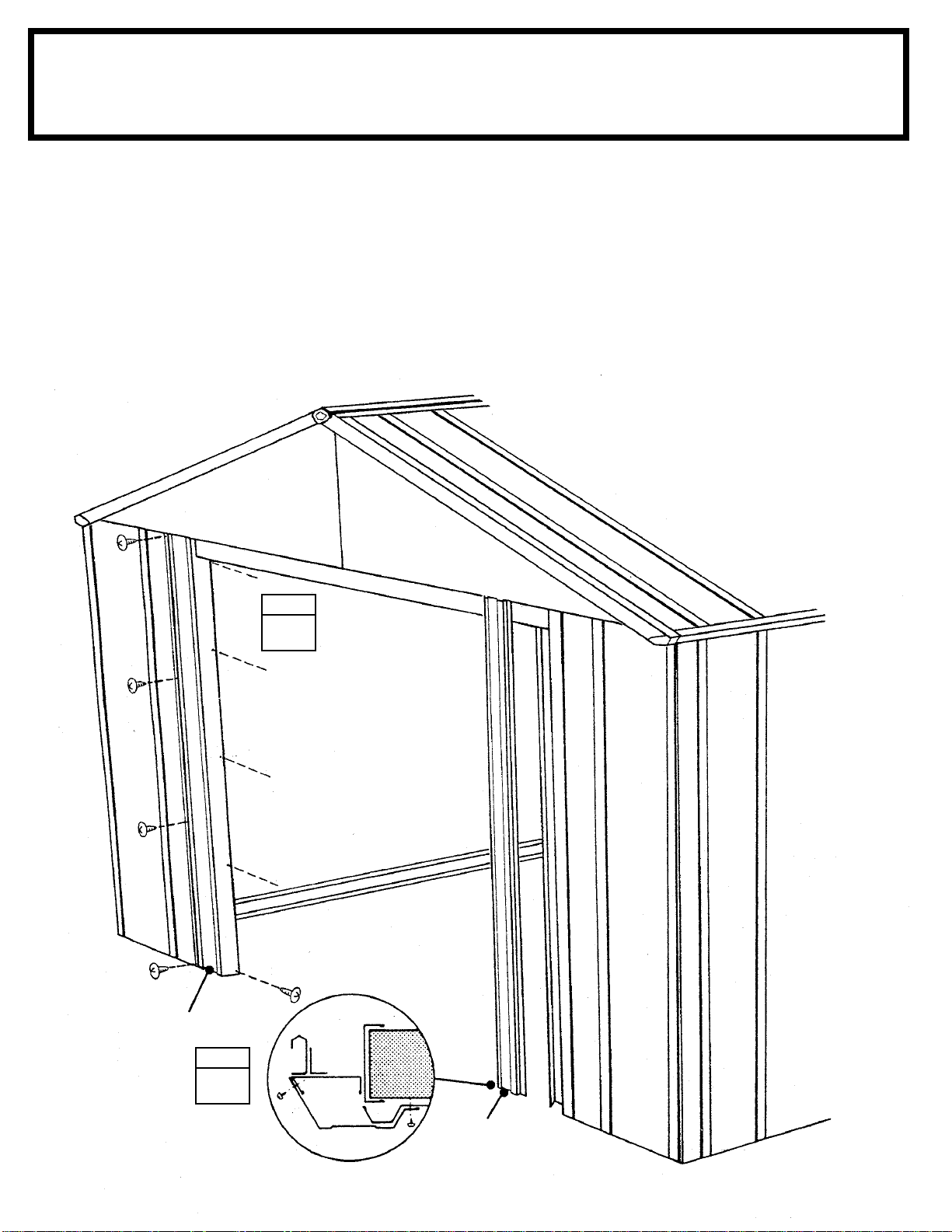
Step 30Step 30
Step 30
Step 30Step 30
BX46
● Parts Needed For ●
Right/Left Door JambsRight/Left Door Jambs
Right/Left Door Jambs
Right/Left Door JambsRight/Left Door Jambs
●●
9488 Right Door Jamb (1) 9488 Right Door Jamb (1)
●
9488 Right Door Jamb (1)
●●
9488 Right Door Jamb (1) 9488 Right Door Jamb (1)
●●
9489 Left Door Jamb (1) 9489 Left Door Jamb (1)
●
9489 Left Door Jamb (1)
●●
9489 Left Door Jamb (1) 9489 Left Door Jamb (1)
11
1Position
11
to right and left track supports with
notched end on top, facing inside
building.
22
2Fasten long flange to track support
22
and short flange to front wall panel
using screws and washers.
right right
right and
right right
left door jambsleft door jambs
left door jambs
left door jambsleft door jambs
STEP
9489
STEP
11
1
11
46
22
2
22
9488
Page 47
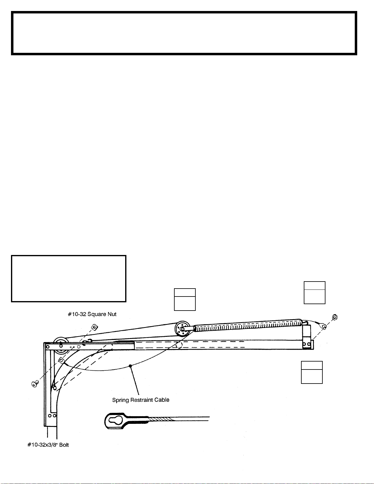
Step 31Step 31
Step 31
Step 31Step 31
BX47
11
1After door has been completely in-
11
stalled, raise door to a full open position. Remove nut from bolt holding
the horizontal track to the spring support bracket, but do not remove bolt.
Spring Restraint CableSpring Restraint Cable
Spring Restraint Cable
Spring Restraint CableSpring Restraint Cable
22
2Slip keyed end of
22
cable cable
cable over shaft of bolt. Replace nut
cable cable
and tighten securely.
33
3Thread spring restraint cable
33
through spring, making sure cable
goes through spring loops on each
end of spring. Fasten to hole shown
on angle of the horizontal track using
a #10-32x3/8" bolt and square nut
through keyed end of cable.
44
4Repeat above installation proce-
44
dure for the other spring.
This spring restraint cable has been
manufactured in accordance with require-
ments of the California Department of
Housing and Community Development.
spring restraintspring restraint
spring restraint
spring restraintspring restraint
NOTENOTE
NOTE
NOTENOTE
STEP
33
3
33
STEP
11
1
11
STEP
22
2
22
47
Page 48
VT1421 VT1421
VT1421
VT1421 VT1421
BX48
SOME FACTS ABOUT RUSTSOME FACTS ABOUT RUST
SOME FACTS ABOUT RUST
SOME FACTS ABOUT RUSTSOME FACTS ABOUT RUST
Rusting is a natural oxidizing process that occurs
when bare metal is exposed to moisture. Problem
areas include screw holes, unfinished edges, or
where scrapes and nicks occur in the protective
coating through normal assembly, handling and
use. Identifying these natural rusting problem areas
and taking some simple rust protection precautions
can help to stop rust from developing, or stop it
quickly as soon as it appears.
VT1431 697.68889 697.68890VT1431 697.68889 697.68890
VT1431 697.68889 697.68890
VT1431 697.68889 697.68890VT1431 697.68889 697.68890
1. Avoid nicking or scraping the coating surface,
inside and out.
2. Use all the washers supplied. In addition to protecting against weather infiltration, the washers protect the metal from being scraped by the screws.
3. Keep roof, base perimeter and door tracks free of
debris and leaves which may accumulate and retain
moisture. These can do double damage since they
give off acid as they decay.
4. Touch up scrapes or nicks and any area of visible
rust as soon as possible. Make sure the surface is
free of moisture, oils, dirt or grime and then apply an
even film of high quality touch-up paint.
704910801
 Loading...