

Page 1
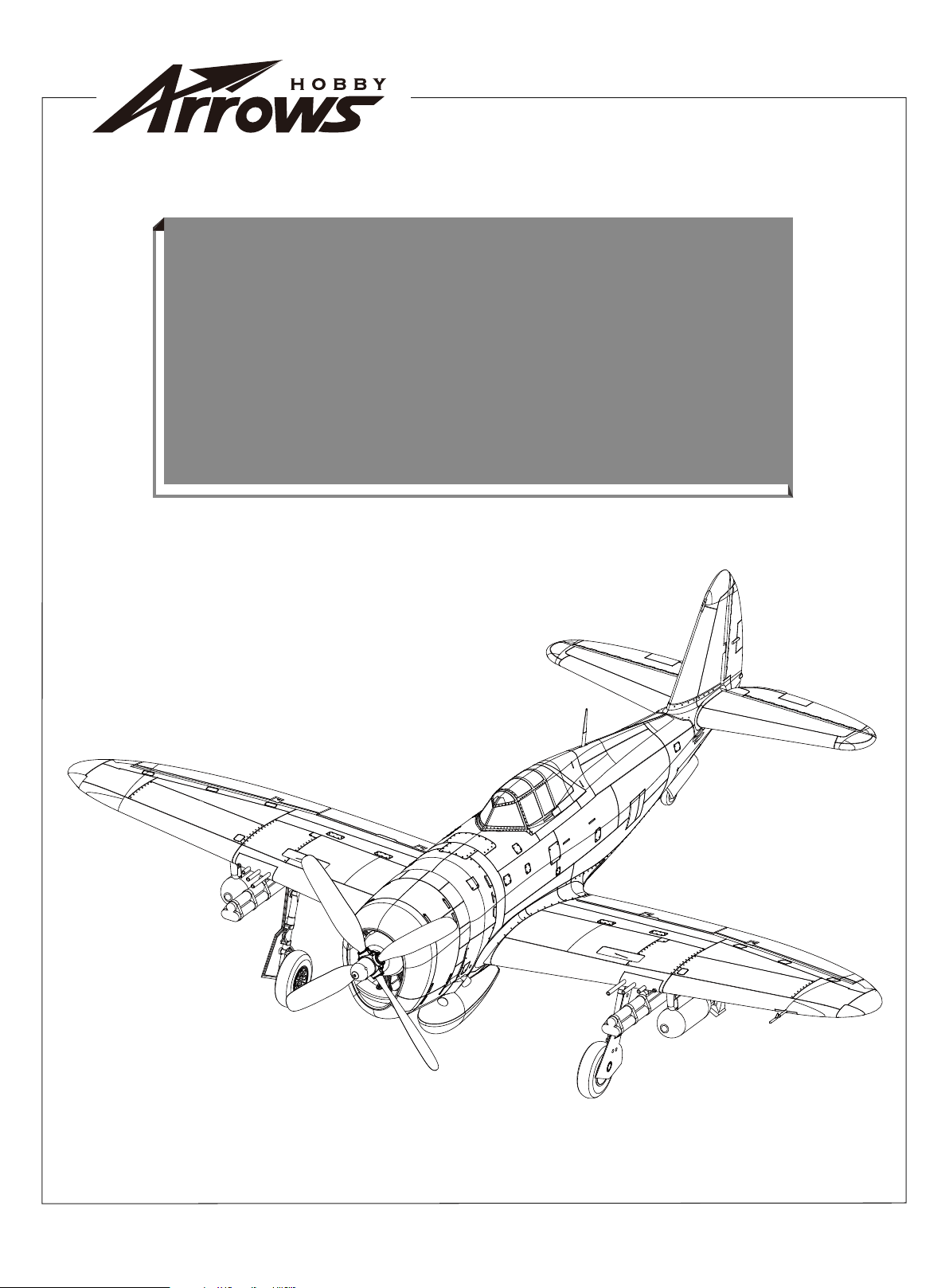
980mm P-47
980mm P-47
Operating Manual
Operating Manual
Page 2

Page 3

Warning:
a reliable and safe manner. Please read the instructions and warnings carefully prior to assembly, setup or use.
As this model aircraft is a sophisticated hobby product, it must be flown with safety and common sense in mind,
failure in doing so may result in injury or property damage. This product is not intended for use by children without
direct adult supervision.
This manual contains important information that will help you maintain and operate your model aircraft in
Safety precautions and warnings
As the user, you are solely responsible for the safe operation and maintenance of this product. Follow the directions
and warnings listed in this manual, as well as that of supporting equipment (chargers, batteries etc.) and always use
common sense.
This is not a toy. Not for children under 14 years of age.
.
Always operate your model in an open area away from buildings, cars, traffic or people. Never operate near peopleespecially children who can wander unpredictably. Never operate in populated areas for any reason, where injury or
damage can occur.
Always keep a safe distance in all directions around your model to avoid collisions or injury. This model is controlled by
a radio signal subject to interference from many sources outside your control. Interference can cause momentary loss
of control.
Never catch the aircraft while it is in flight, the structure of the fuselage was not designed and protected for this purpose.
Never operate your model in bad weather, including in excessively windy or precipitating conditions.
Never operate your model with low transmitter batteries.
Keep your throttle quadrant in its lowest position prior and after every flight. Use the throttle cut function if able.
Always use fully charged batteries and move batteries before disassembly.
Avoid water exposure to all equipment not specifically designed and protected for this purpose.
Avoid cleaning this product with chemicals.
Never lick or place any part of your model in your mouth as it could cause serious injury or even death.
Keep all chemicals, small parts and anything electrical out of the reach of children.
02
Page 4
Introduction
The Republic P-47 Thunderbolt was a World War II era fighter aircraft that served with the United States Army Air Forces.
Weighing in at eight tonnes when fully loaded, it was one of the heaviest fighters and ground attack aircraft of its era.
Carrying M8 rocket pods and a 2500lb payload of bombs, it was highly effective in ground attack missions.
Arrow Works is proud to introduce the intricately detailed 980mm P-47. Featuring retractable landing gear, a realistic four
bladed propeller, removable auxiliary fuel tank, bombs and rocket pods- the P-47 faithfully replicates its full-sized World
War II counterpart.
Features:
• Power system- 3536 850KV Motor, 40A ESC.
• Highly detailed: realistic and functional flaps and landing gear.
Removable auxiliary fuel tank, bombs and rocket pods. Panel
lines, LED lights and a painted pilot figure.
• Simple connector minimizes the need to connect multiple
servo leads.
• Oversized battery compartment for a multitude
of battery sizes and capacities.
• Preinstalled ball-linked servo horns, increased
control precision.
Table of contents Specifications
Introduction
Specifications
Kit contents
Model Assembly
Battery installation
Receiver diagram
Preflight check
Clevis installation
Control horn and servo arm settings
Center of gravity(CG)
Before flying the model
Flying course
Trouble shooting
Spare parts list content
······················································3
······················································3
························································3
···················································4
···············································6
·················································6
·····················································6
·················································7
··························8
············································8
·········································8
······················································9
················································10
········································10
Wingspan
Overall length
Flying weight
Motor size
Wing load
Wing area
ESC
Servo
Recommended battery
980mm(38.6in)
865mm(34.0in)
~ 1100g
3536-KV850
65.5g/dm²(0.15oz/in²)
16.8dm²(261sq.in)
40A
9g Servo x 6
11.1V 2200mAh 25C
Kit contents
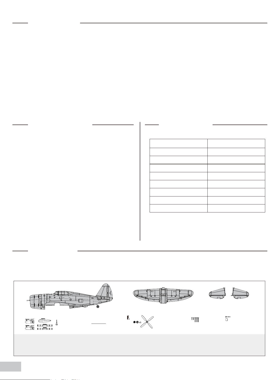
Before assembly, please inspect the contents of the kit. The photo below details the contents of the kit with labels. If any
parts are missing or defective, please identify the name or part number (refer to the spare parts list near the end of the
manual) then contact your local shop.
A.
D. E.
A: Fuselage
B: Main wing
C: Horizontal stabilizer
03
B. C.
D: Bomb, Rocket pods, Auxiliary fuel tank, antenna
E: C
F: Propeller and spinner set
G. H.
G: Screws
H: Pitot tube
Page 5
Model assembly
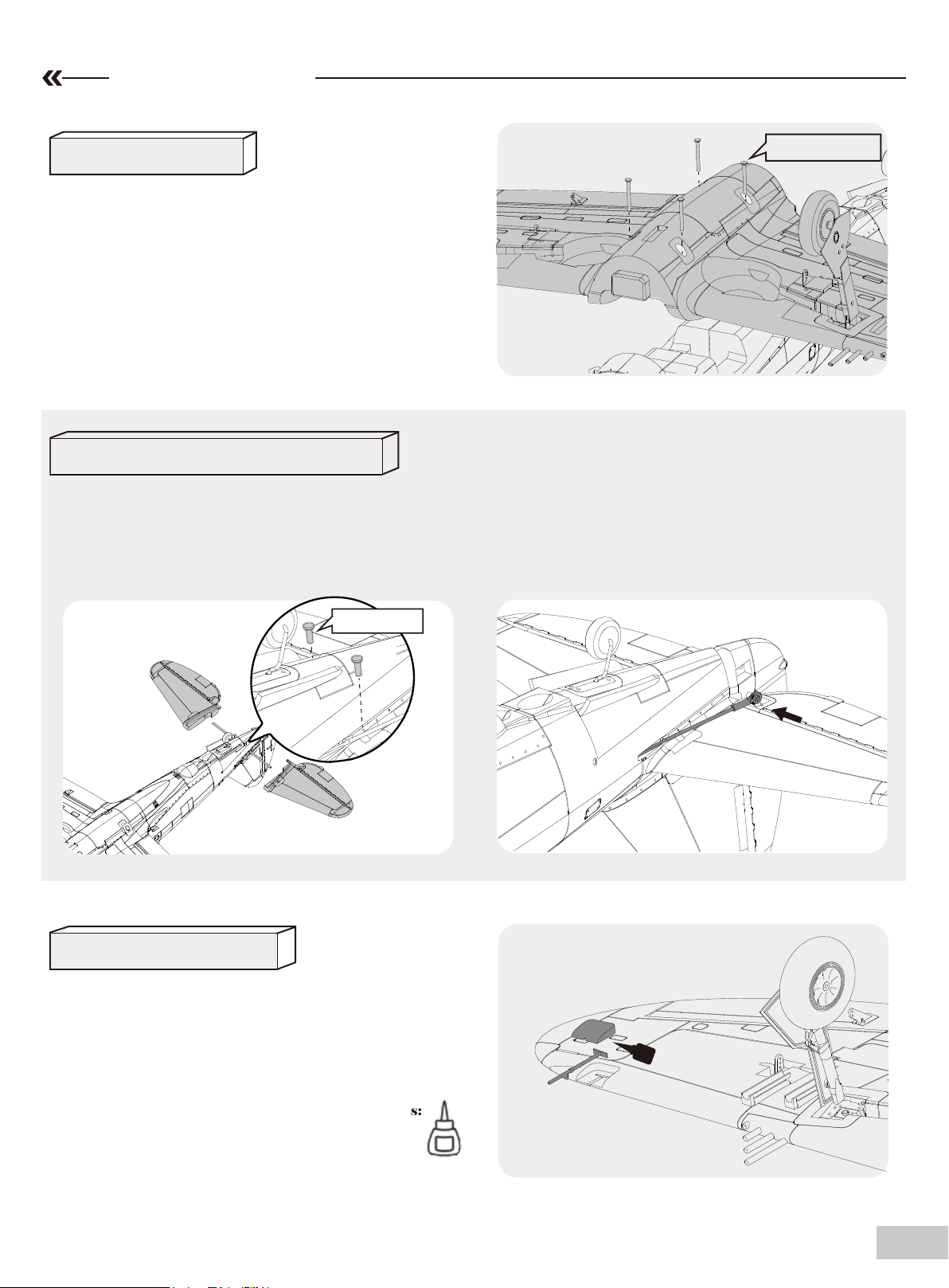
Wing installation
1. Attach the wing onto the fuselage, ensuring not to
pinch any of the servo wires.
2.Attach the wing to the fuselage with included screws as
shown. Do not over tighten the screws.
HKM3.0*32mm
Horizontal stabilizer installation
1.Slide the horizontal stabilizer spar into the slot near the rear of the fuselage.
2.Install the two pieces (left and right) horizontal stabilizer as shown. Ensure the control horn faces down.
3.Secure the two horizontal stabilizer pieces in place using the included screws.
4.Attach the ball link to the elevator control horn.
KA2.6*12mm
Pitot tube installation
1. Carefully apply foam safe CA to the base of pitot tube and
place the pitot tube into the pocket as shown.
2.Carefully apply foam safe CA to the foam block and place
the foam block into the cut-out.
Required Adhesives:
Medium CA
04
Page 6
Model assembly
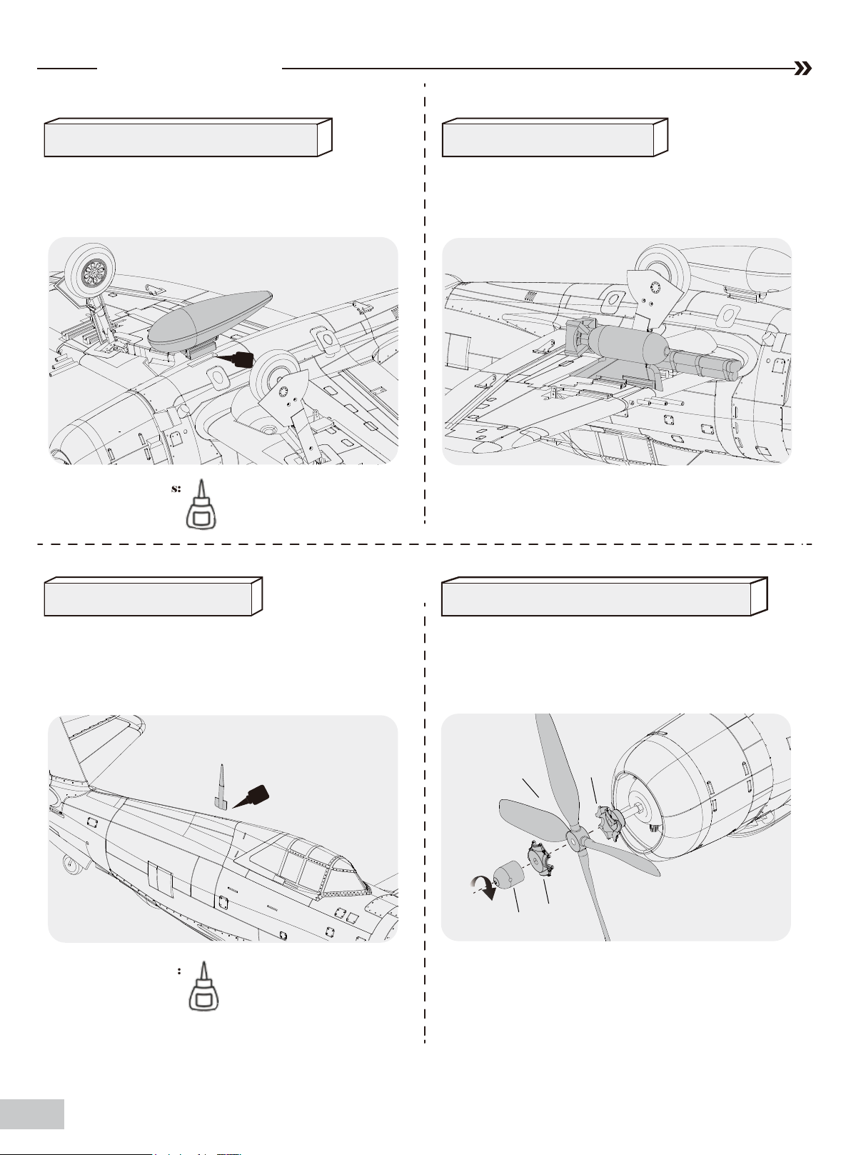
Auxiliary fuel tank installation
1.Carefully apply foam safe CA to the base and side of
the auxiliary fuel tank pocket and place the oil tank into
the pocket.
Required Adhesives:
Medium CA
Armament installation
1. Slide the bombs and rockets onto the rails.
Antenna installation Propeller and spinner installation
1. Apply the foam safe CA to the antenna and place the
antenna into the slot as shown.
Required Adhesives:
Medium CA
1. Assemble the propeller and spinner as shown below.
Note:The motor should rotate clockwise when viewing
the plane from the rear.
b
d
a
c
05
Page 7
Battery installation
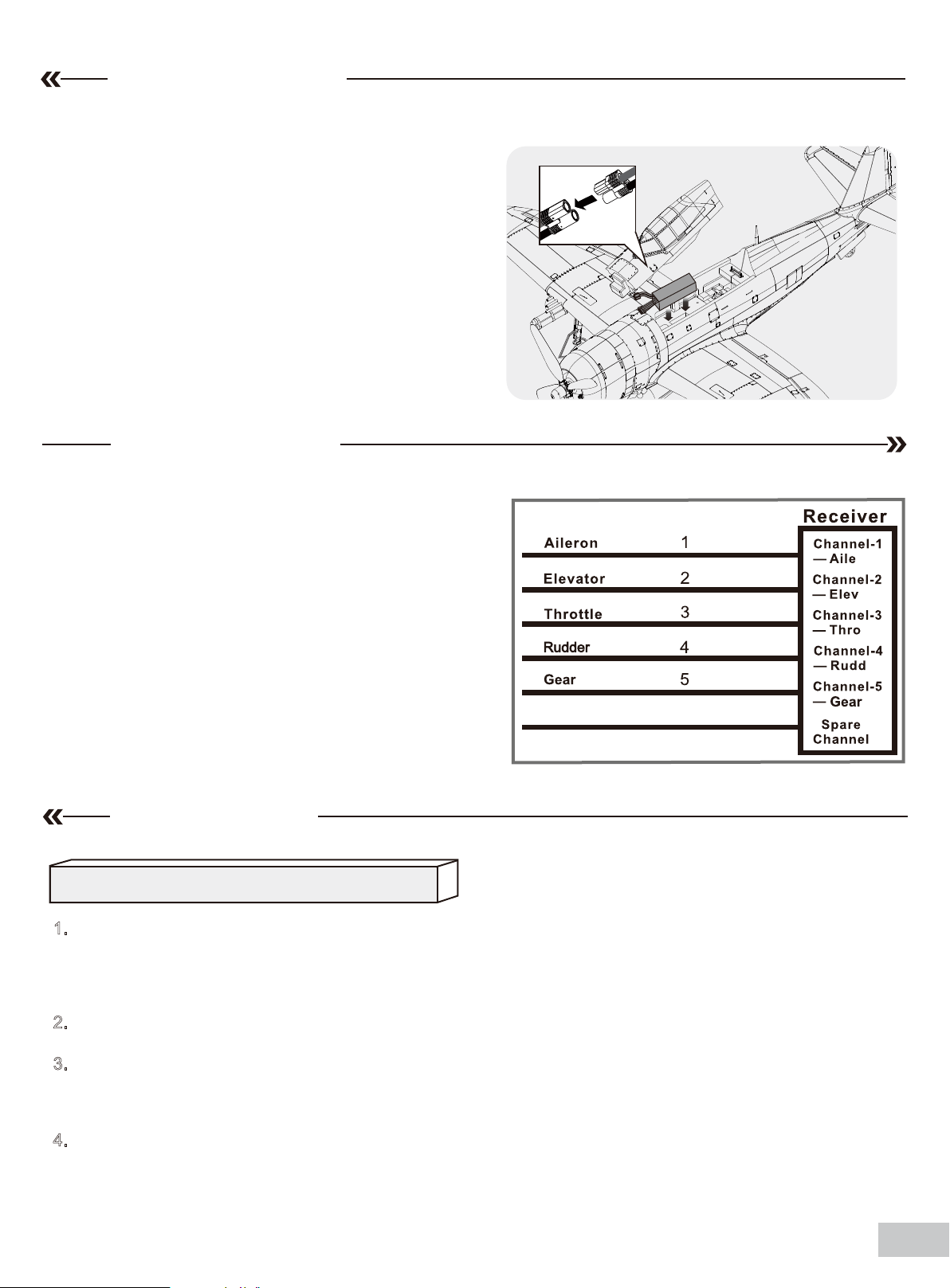
1. Remove the battery hatch.
2. Remove the hook and loop tape from the fuselage. Apply
the looped surface to the battery.
3. Install the battery into the fuselage- securing it with the
preinstalled battery straps.
Note: The weight of each battery may vary due to different
manufacturing techniques. Move the battery fore or aft to
achieve the optimal center of gravity.
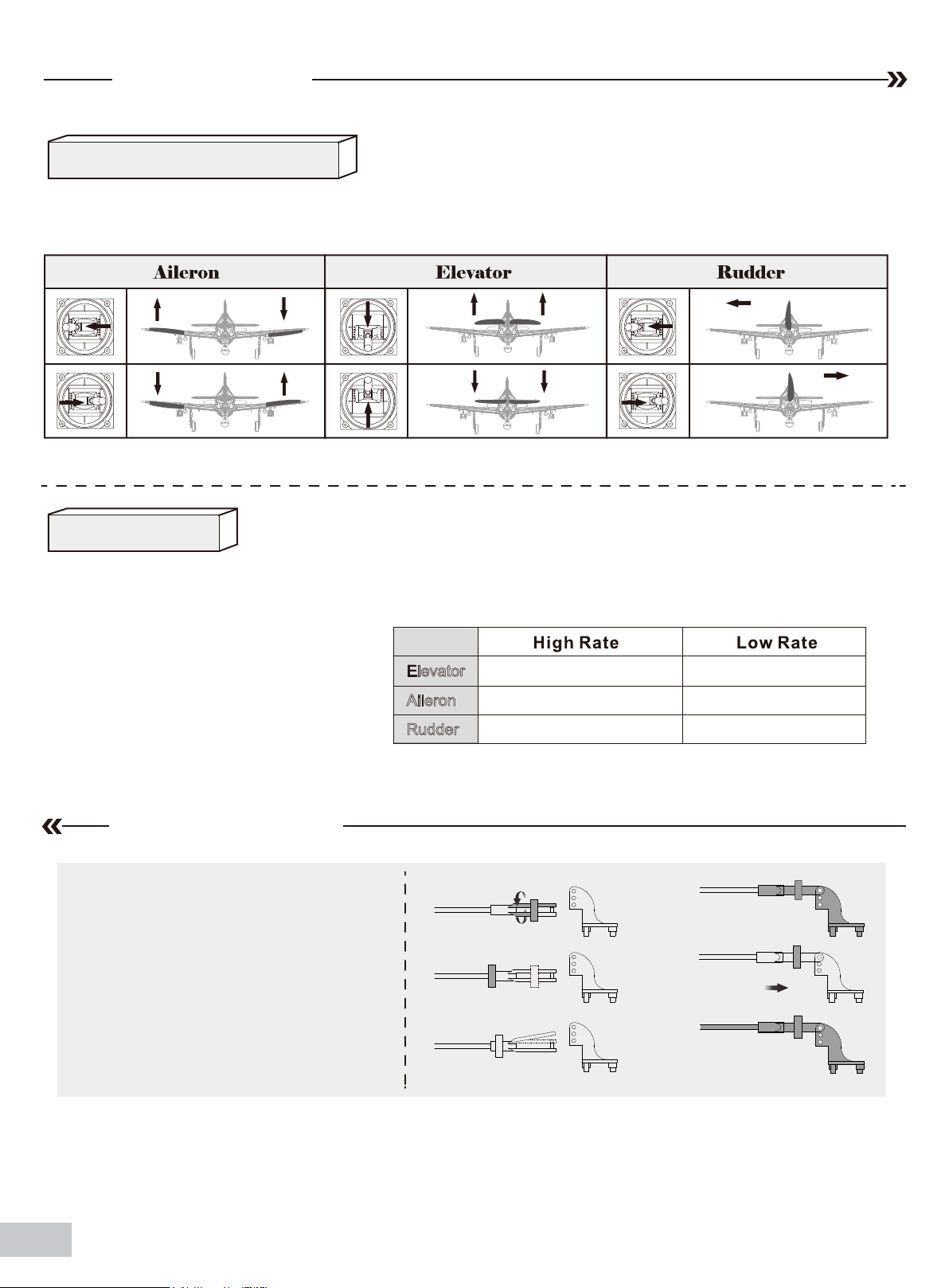
Receiver diagram
The cables from the servo connector board should be
connected to your receiver in the order shown. Note that the
LEDs can be powered by any spare channel on the receiver.
Tuck the wire leads into the recessed cavity towards the rear
of the battery hatch.
Spare
6
Preflight check
Important ESC and model information
1. The ESC included with the model has a safe start. If the motor battery is connected to the ESC and the throttle stick is not in the low
throttle or off position, the motor will not start until the throttle stick is moved to the low throttle or off position. Once the throttle stick is
moved to the low throttle or off position, the motor will emit a series of beeps. Several beeps with the same tune means the ESC has
detected the cells of the battery. The count of the beeps equals the cells of the battery. The motor is now armed and will start when the
throttle is moved.
2.
The motor and ESC come pre-connected and the motor rotation should be correct. If for any reason the motor is rotating in the wrong
direction, simply reverse two of the three motor wires to change the direction of rotation.
3. The motor has an optional brake setting. The ESC comes with brake switched off and we recommend that the model be flown with
the brake off. However, the brake could be accidentally switched on if the motor battery is connected to the ESC while the throttle stick
is set at full throttle. To switch the brake off, move the throttle stick to full throttle and plug in the motor battery. The motor will beep one
time. Move the throttle stick to low throttle or the off position. The motor is ready to run and the brake will be switched off.
4. Battery Selection and Installation. We recommend the 11.1V 2200mAh 25C Li-Po battery. If using another battery, the battery must
be at least a 11.1V 2200mAh 25C battery. Your battery should be approximately the same capacity, dimension and weight as the 11.1V
2200mAh 25C Li-Po battery to fit the fuselage without changing the center of gravity significantly.
06
Page 8
Preflight check
transmitter and model setup
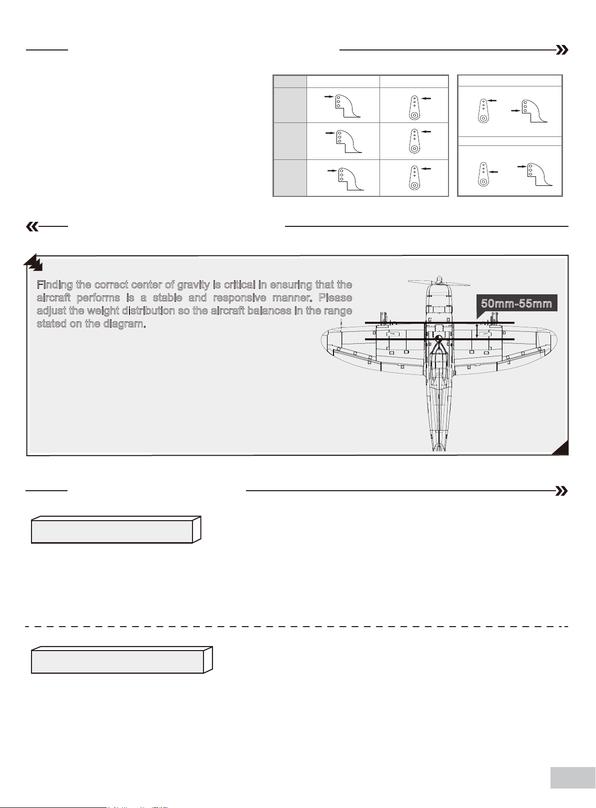
After assembly and prior to your first flight, make sure all control surfaces respond correctly to your transmitter by referring
to the diagram below.
Control throws
The suggested control throw setting for the P-47 are as follows (dual rate setting):
Tip: The maiden flight should always be
flown using low rates, fly the aircraft until you
are familiar with its characteristics prior to
trying high rates. Make sure the aircraft is
flying at a decent altitude and speed prior to
using high rates, as the aircraft will be sensitive to control inputs with the larger control
surface movements.
Aileron
Rudder
14mm up / downElevator
14mm up / down
16mm left / right
10mm up / down
10mm up / down
12mm left / right
Clevis installation
1.Pull the tube from the clevis to the linkage.
2.Carefully spread the clevis, then insert the
clevis pin into the desired hole in the control
horn.
3.Move the tube to hold the clevis on the
control horn.
a.
b.
c.
d.
e.
f.
07
Page 9
Control horn and servo arm settings
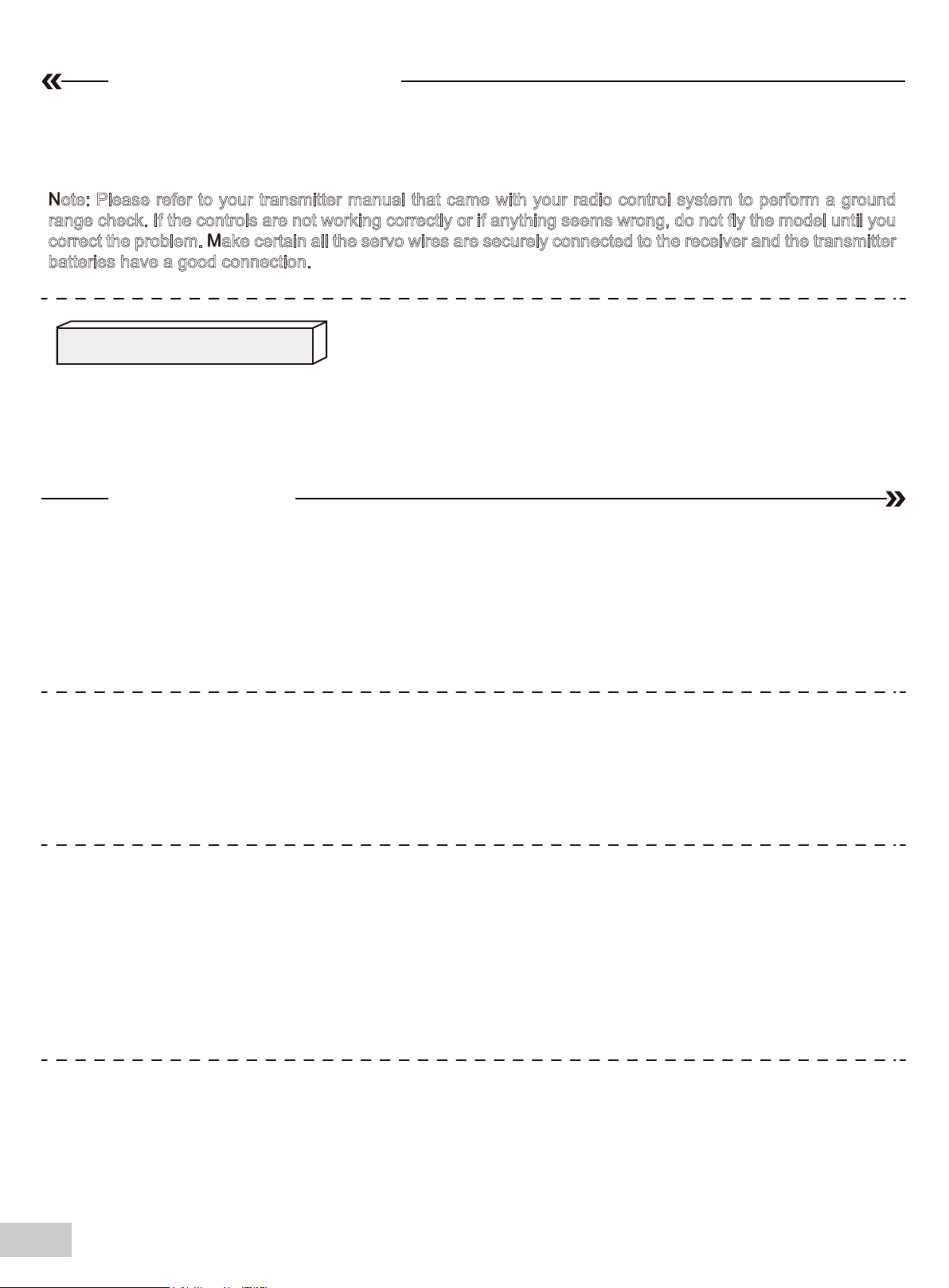
Horns
1. The table shows the factory settings for the
control horns and servo arms. Fly the aircraft at the
factory settings before making changes.
2. After flying, you may choose to adjust the linkage
positions for the desired control response.
ElevatorRudderAilerons
Finding the center of gravity
Finding the correct center of gravity is critical in ensuring that the
aircraft performs is a stable and responsive manner. Please
adjust the weight distribution so the aircraft balances in the range
stated on the diagram.
• Depending on the capacity and weight of your choosen flight
batteries, move the battery forward or backward to adjust the
center of gravity.
Arms
More control throw
Less control throw
50mm-55mm
• If you cannot obtain the recommended CG by moving the battery to a
suitable location, you can also install a counterweight to achieve correct
CG. However, with the recommended battery size, a counterweight is not
required. We recommend flying without unnecessary counterweight.
Before flying the model
Find a suitable flying site
Find a flying site clear of buildings, trees, power lines and other obstructions. Until you know how much area will be required
and have mastered flying your plane in confined spaces, choose a site which is at least the size of two to three football fields
- a flying field specifically for R/C planes is best. Never fly near people - especially children, who can wander unpredictably.
Performing a range check
A radio range check should be performed prior to the first flight of the day. This test may assist you in detecting electronic
problems that may lead to a loss of control- problems such as low transmitter batteries, defective or damaged radio components or radio interference. This usually requires an assistant and should be done at the flying site.
08
Page 10
Before flying the model
Always turn your transmitter on first. Install a fully charged battery in the battery bay, then connect it to the ESC. In this
process, make sure that the throttle cut functionality is on, and that the throttle stick is secured in its lowest position- otherwise, the propeller/fan will engage and possibly cause bodily harm.
Note: Please refer to your transmitter manual that came with your radio control system to perform a ground
range check. If the controls are not working correctly or if anything seems wrong, do not fly the model until you
correct the problem. Make certain all the servo wires are securely connected to the receiver and the transmitter
batteries have a good connection.
Monitor your flight time
Monitor and limit your flight time using a timer (such as a stopwatch or on the transmitter, if available). As modern Lithium
Polymer batteries are not designed to discharge completely, when the battery runs low, the ESC will lower then completely
cut the power to the motors to protect the battery.Often (but not always) power can be briefly restored after the motor cuts
off by holding the throttle stick all the way down for a few seconds.To avoid an unexpected dead-stick landing on your first
flight,set your timer to a conservative 4 minutes. When your alarm sounds you should land right away.
Flying course
Take off
Point the aircraft into the wind while slowly applying power until the aircraft starts to track straight, use the rudder when
necessary. When the aircraft reaches takeoff speed, ease back on the elevator stick until the aircraft is climbing at a
constant rate without decelerating. Climbing at too steep of an angle at the relatively low speeds of a takeoff-climb may
result in an aerodynamic stall.
Flying
Always choose a wide-open space for flying your plane. It is ideal for you to fly at a sanctioned flying field. If you are
not flying at an approved site always avoid flying near houses, trees, wires and buildings. You should also be careful to
avoid flying in areas where there are many people, such as busy parks, schoolyards, or soccer fields. Consult laws and
ordinances before choosing a location to fly your aircraft. After takeoff, gain some altitude. Climb to a safe height before
trying technical manoeuvres.
Landing
Land the aircraft when you start to feel sluggish motor response. If using a transmitter with a timer, set the timer so you
have enough flight time to make several landing approaches.The model’s three point landing gear allows the model to land
on hard surfaces. Align model directly into the wind and fly down to the ground. Fly the airplane down to the ground using
1/4-1/3 throttle to keep enough energy for proper flare. Before the model Zouches down, always fully decrease the throttle
to avoid damaging the propeller or other components. The key to a great landing is to manage the power and elevator all
the way to the ground and set down lightly on the main landing gear. After a few flights you will find the model can be set
down lightlyon the mains and you can hold the nose wheel off balancing themodel on the mains until it slows and gently
settles the nose.
Maintenance
Repairs to the foam should be made with foam safe adhesives such as hot glue, foam safe CA, and 5min epoxy.
When parts are not repairable, see the spare parts list for ordering by item number.
Always check to make sure all screws on the aircraft are tightened. Pay special attention to make sure the spinner is
firmly in place before every flight.
09
Page 11
Troubleshooting
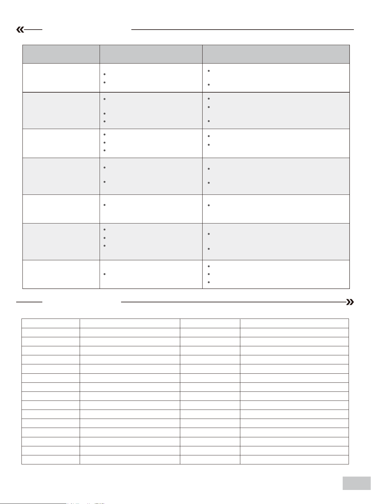
Problem Possible Cause Solution
Aircraft will not respond to
the throttle but responds to
other controls.
Excessive vibration or
propeller noise.
Reduced flight time or
aircraft underpowered.
Control surfaces
unresponsive or sluggish.
Controls reversed.
Motor loses power
Motor power pulses then
motor loses power.
ESC is not armed.
Throttle channel is reversed.
Damaged spinner, propeller,
motor or motor mount.
Loose propeller and spinner parts.
Propellor installed backwards.
Flight battery charge is low.
Propeller installed backward.
Flight battery damaged.
Control surface, control horn,
linkage or servo damage.
Wire damaged or connections
loose.
Channels are reversed in the
transmitter.
Damage to motor, or battery.
Loss of power to aircraft.
ESC uses default soft Low Voltage
Cutoff(LVC).
Lower throttle stick and throttle trim to lowest
settings.
Reverse throttle channel on transmitter.
Replace damaged parts.
Tighten parts for propeller adapter, propeller
and spinner.
Remove and install propeller correctly.
Completely recharge flight battery.
Replace flight battery and follow flight battery
instructions.
Replace or repair damaged parts and adjust
controls.
Do a check of connections for loose wiring.
Do the control direction test and adjust controls for
aircraft and transmitter.
Do a check of batteries, transmitter, receiver, ESC,
motor and wiring for damage(replace as needed).
Land aircraft immediately and recharge flight battery.
LED on receiver flashes
slowly.
Spare parts list
AHAA101
AHAA102
AHAA103
AHAA104
AHAA105
AHAA106
AHAA107
AHAA108
AHAA109
AHAA110
AHAA111
AHAA112
AHAA113
AHAA114
AHAA115
AHAA116
Check connection from ESC to receiver.
Power loss to receiver.
Check servos for damage.
Check linkages for binding.
Fuselage
Main wing set
Horizontal stabilizer
Cockpit
Cowl
Bomb set
Rocket pods
Auxiliary fuel tank
Machine gun
Spinner
Pitot tube
Wing bolt plate
Antenna
Main landing gear set
Main landing gear system
Rear landing gear set Multi-connector set
AHAA117
AHAA118
AHAA119
AHAA120
AHAA121
AHAA122
AHAA123
AHMount001
AHBoard001
AHShaft001
AHRE001
AHPROP001
AHKV850
AHESC40A
AHSER9GP
AHCON001
The outer fairing door
Linkage rod
Screw set
Decal sheet
Multi engine aiplanes
LED
Lamp cover
Motor mount
Motor board
Motor shaft
E-retract
Propeller
Brushless motor 3536-KV850
40A ESC
9g gear servo positive
10
Page 12

 Loading...