

Page 1
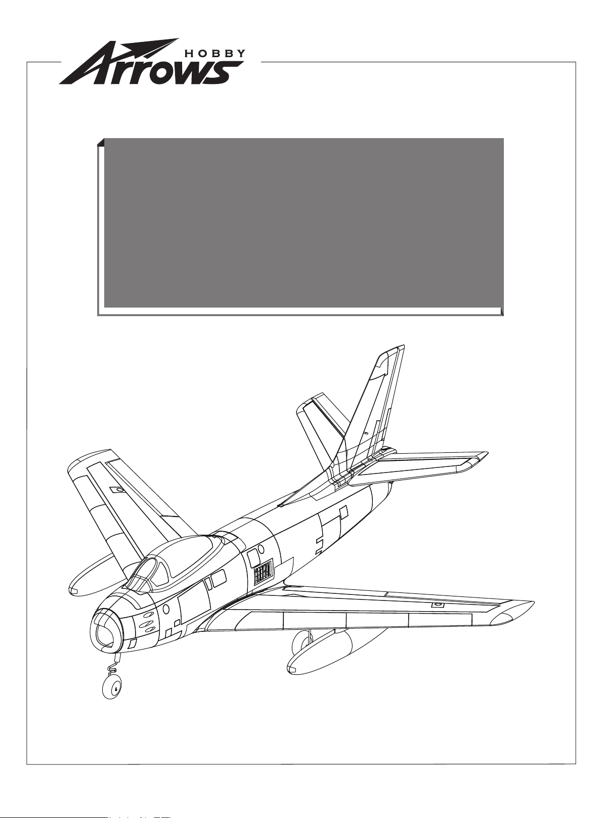
64mm F-8664mm F-86
Operating ManualOperating Manual
www.arrowshobby.com
Page 2
WARNING:
a reliable and safe manner. Please read the instructions and warnings carefully prior to assembly, setup or use.
As this model aircraft is a sophisticated hobby product, it must be flown with safety and common sense in mind, failure
in doing so may result in injury or property damage. This product is not intended for use by children without direct adult
supervision.
This manual contains important information that will help you maintain and operate your model aircraft in
Safety precautions and Warnings
As the user, you are solely responsible for the safe operation and maintenance of this product. Follow the directions
and warnings listed in this manual, as well as that of supporting equipment (chargers, batteries etc.) and always use
common sense.
This is not a toy. Not for children under 14 years of age.
Always operate your model in an open area away from buildings, cars, traffic or people. Never operate near
people-especially children who can wander unpredictably. Never operate in populated areas for any reason, where
injury or damage can occur.
Always keep a safe distance in all directions around your model to avoid collisions or injury. This model is controlled
by a radio signal subject to interference from many sources outside your control. Interference can cause momentary
loss of control.
Never catch the aircraft while it is in flight, the structure of the fuselage was not designed and protected for this
purpose.
Never operate your model in bad weather, including in excessively windy or precipitating conditions.
Never operate your model with low transmitter batteries.
Keep your throttle quadrant in its lowest position prior and after every flight. Use the throttle cut function if able.
Always use fully charged batteries and move batteries before disassembly.
Avoid water exposure to all equipment not specifically designed and protected for this purpose.
Avoid cleaning this product with chemicals.
Never lick or place any part of your model in your mouth as it could cause serious injury or even death.
Keep all chemicals, small parts and anything electrical out of the reach of children.
02
Page 3
Introduction
The North American F-86 Sabre was the first US fighter aircraft designed using the German research that showed a 35 degree thin
swept wing gave superior transonic performance. The Sabre was the equal of its well-known Korean War opponent, the Mig-15. It
was the highest production US jet fighter ever made, with total production of 9860 units. It was manufactured in many variants, and the
Navy FJ fighter was a modified version suited for carrier operations. It was the first fighter equipped with air-to-air missiles, and later
versions were supersonic in a dive. All in all, it is a classic.
While Arrows Hobby has introduced a number of EDF jets, from the hand tossed Viper to the high end MiG-29 and F-15, our engineering team began with the Marlin 64mm EDF, still the best EDF trainer made. The F-86 is the successor to the Marlin with fixed gear for
strength and the same full 5-channel performance with flaps. The plane has excellent performance and agility at high speed and stability during landings.
The smooth 12-blade 64mm fan sounds more realistic than older 5-blade 64mm units others use. Because of the more powerful 2840
3150KV motor and a 40 amp ESC, this plane is capable of top performance even though it is larger than other 64mm F-86’ s, with maneuvers such as rolling, diving, looping and inverted flight. The quick release landing gear allow for fast transition from ground take-off
to hand launch and facilitates easy transport.
The EPO foam is tough and at 820mm length and 860mm wingspan, it is a perfect 1/10 scale of the original full-scale plane. The contours, panel lines and markings are highly accurate and realistic. The special water-based paint has a very realistic look. Assembly is
fast and simple using only a few screws.
Get ready for a new experience in EDF’ s with the Arrows 64mm F-86 Sabre.
Features:
• 12-bladed 64mm EDF, 2840-3150KV motor, 40A ESC with 9g
servo
• Highly realistic scale components: panel lines, functional flaps,
dual drop tanks
• Steerable nose gear for enhanced ground maneuverability
• High-quality rubber tires
• Preinstalled ball-linked linkages for precise surface movements
• Carbon reinforced airframe
• Fantastic low-speed performance and aerobatic capabilities
Table of contents Specifications
Introduction
Specifications
Kit contents
Model Assembly
Battery installation
Receiver diagram
Preflight check
Control horn and servo arm settings
Center of gravity(CG)
Before flying the model
Flying course
Trouble shooting
Spare parts list content
················································ 3
·············································· 3
··············································· 3
·········································· 4
········································ 7
·····
···································· 7
············································ 7
················· 8
··································· 9
·································· 9
············································ 10
········································· 11
································· 11
Wingspan
Overall length
Flying weight
Motor size
Wing load
Wing area
ESC
Servo
Recommended battery
860mm(33.8in)
820mm(32.3in)
~ 1050g
2840-KV3150
69g/dm²(0.15oz/in²)
15.2dm²(235sq.in)
40A
9g Servo x 8
4S 2200-2600mAh 35C
Kit contents
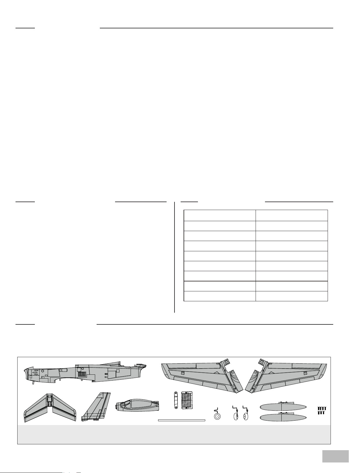
Before assembly, please inspect the contents of the kit. The photo below details the contents of the kit with labels. If any
parts are missing or defective, please identify the name or part number (refer to the spare parts list near the end of the
manual) then contact your local shop.
A. B.
C. D. E. F.
A: Fuselage
B: Main wing set
C: Horizontal stabilizer
D: Vertical stabilizer
E: Canopy
F: Wing bolt plastic set
G.
G: Wing pipe
H: Front landing gear
K. H. I. J.
I: Main landing gear set
J: Auxiliary fuel tank (7-HKM3x10mm)
K: Screw Set
03
Page 4
Model assembly
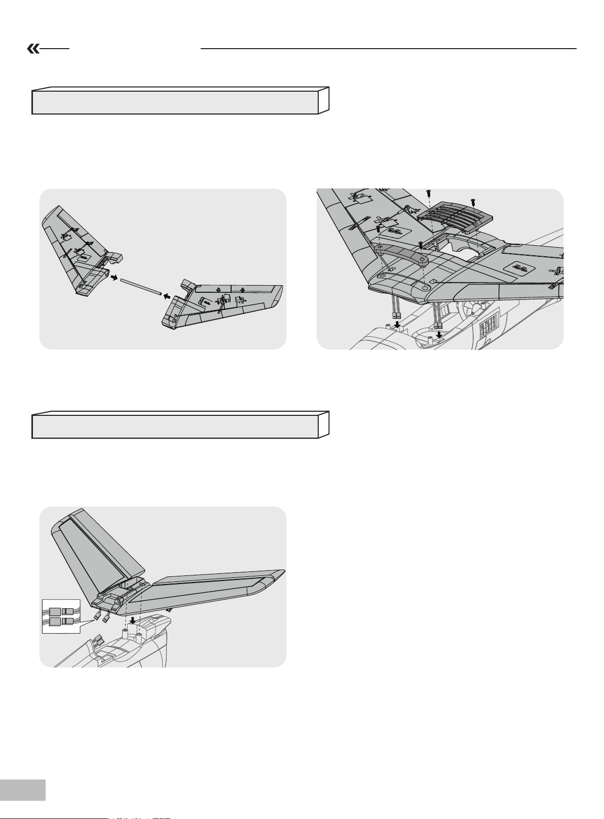
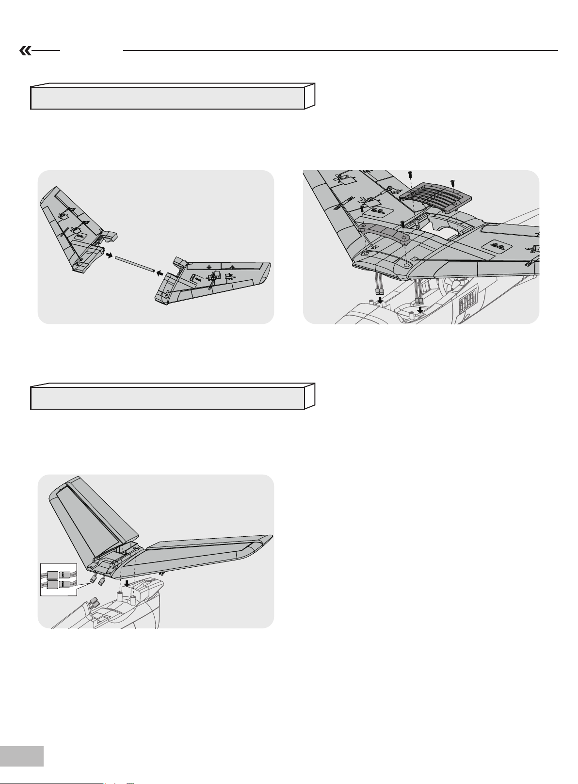
Main wing installation
1.Install the wing spar through the main wing set
pass-through as shown.
Horizontal stabilizer installation
2. Guide the servo wire into the cockpit as shown, fix
the main wing to fuselage using the included plastic
parts and screws, and then connect the Y-harness
wires of CH1 and CH6.
1.Connect the elevator servo connectors to the
servo extensions in the fuselage.Install the horizontal stabilizer into the slot in the fuselage.
04
Page 5
Model assembly
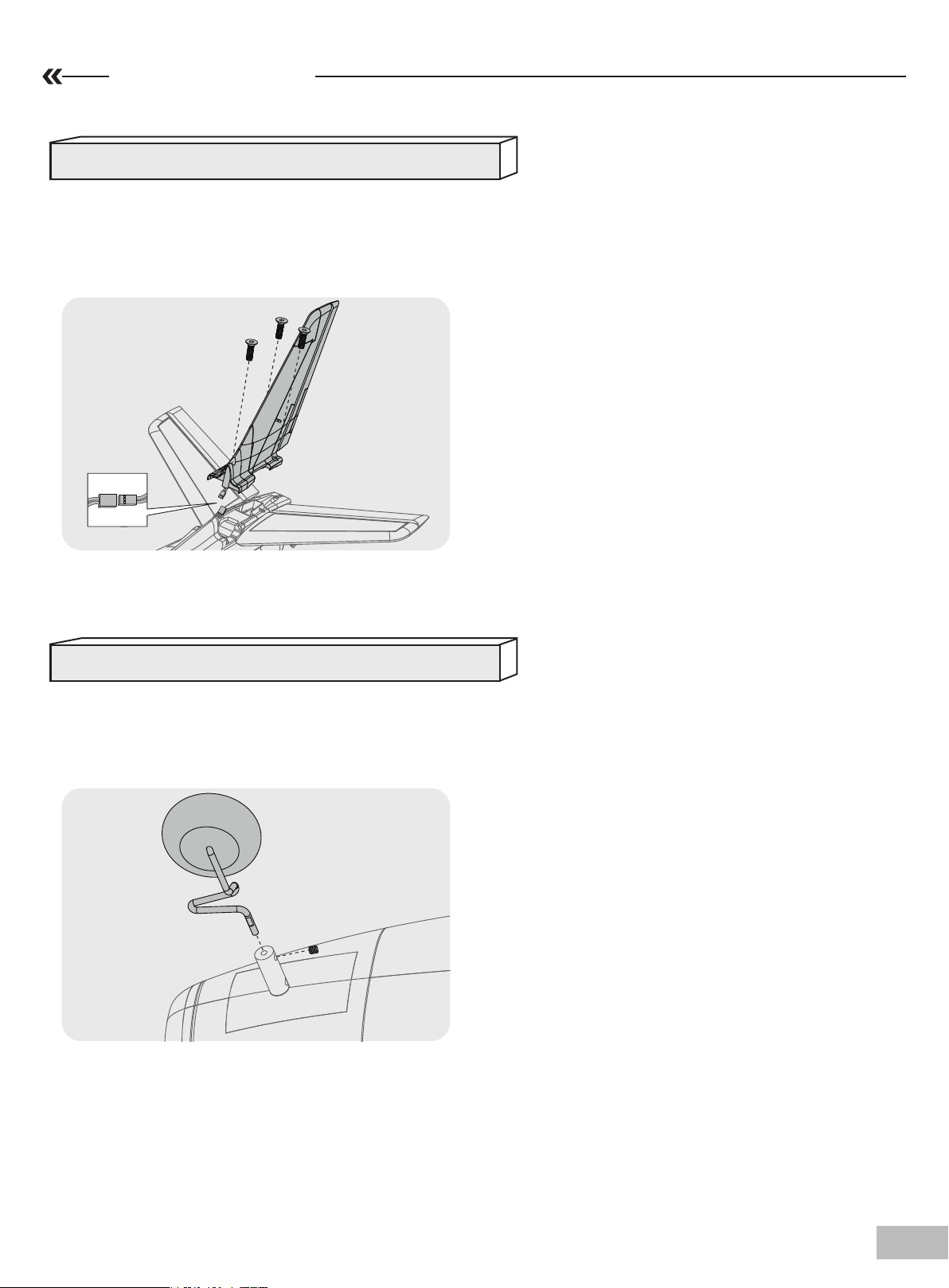
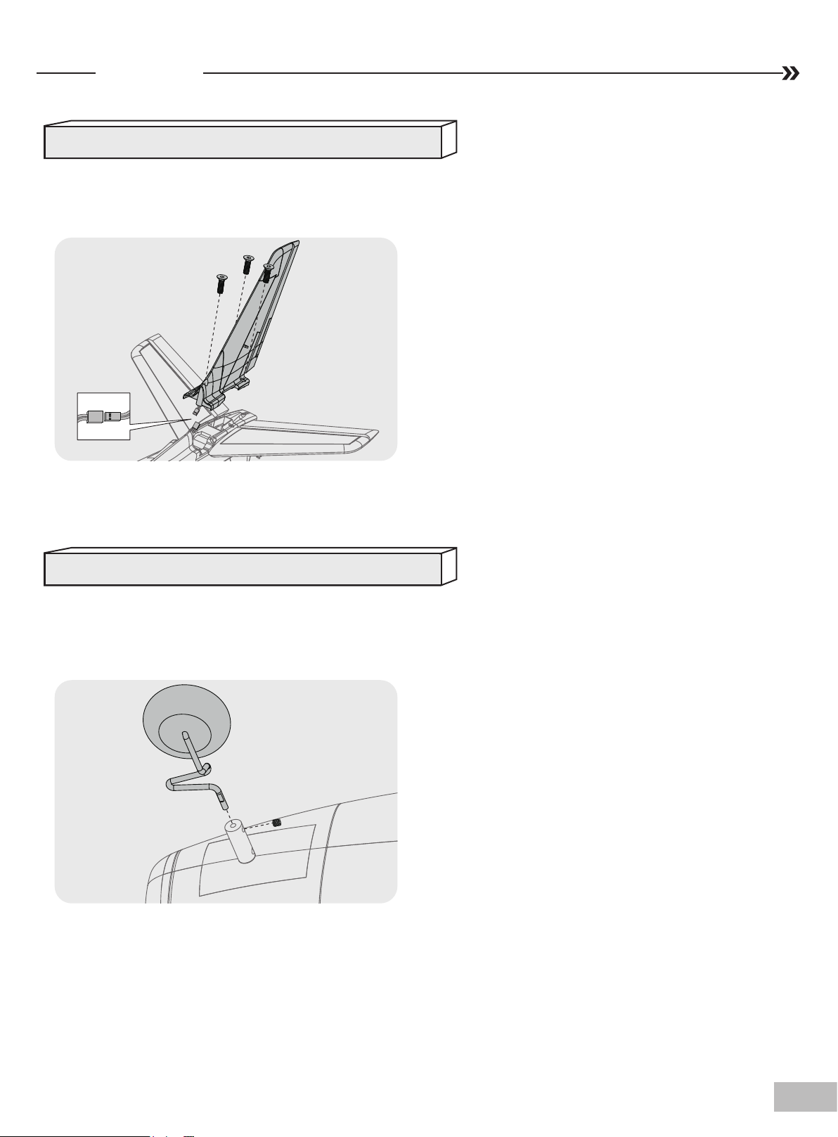
Vertical stabilizer installation
1.Connect the rudder servo connectors to the servo
extensions in the fuselage. Install the vertical tail into
the slot in the fuselage and secure with the included
screws.
Landing gear installation
1.Install the front landing gear into the slot at the
bottom of fuselage and fix with included screw as
shown.
05
Page 6
Model assembly
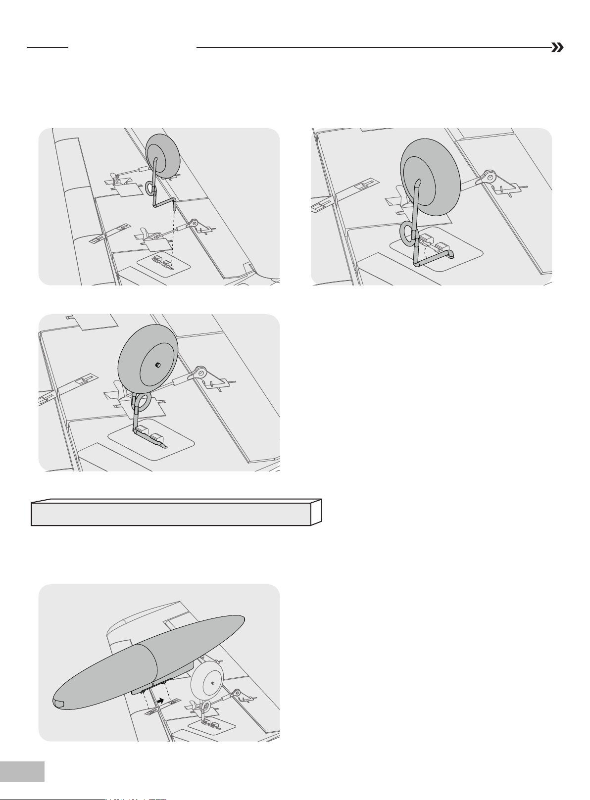
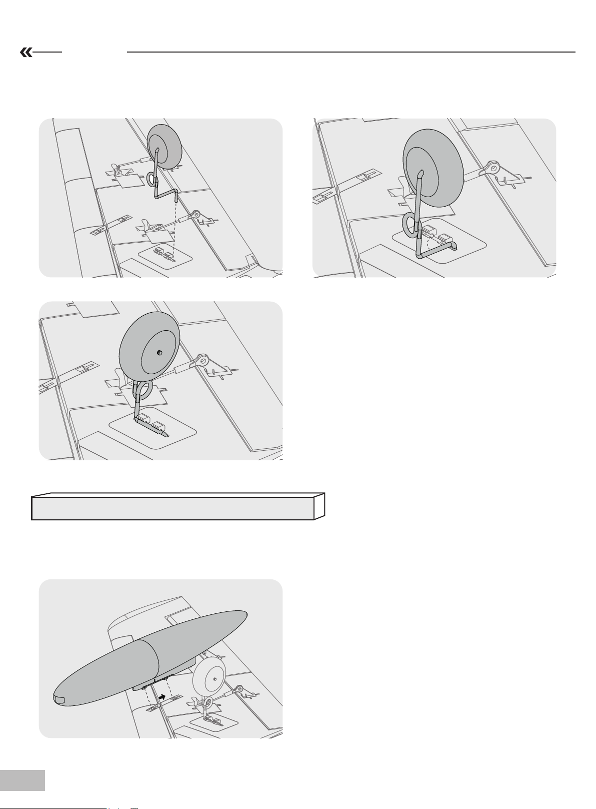
2.Insert the main landing gear assembly into the
wing landing gear slot and pivot 90 degrees to lock
the landing gear in place.
Note: Main landing gear differs left & right.
Auxiliary fuel tank installation
1. Install the fuel tank onto the wing slot.
06
Page 7
Battery installation
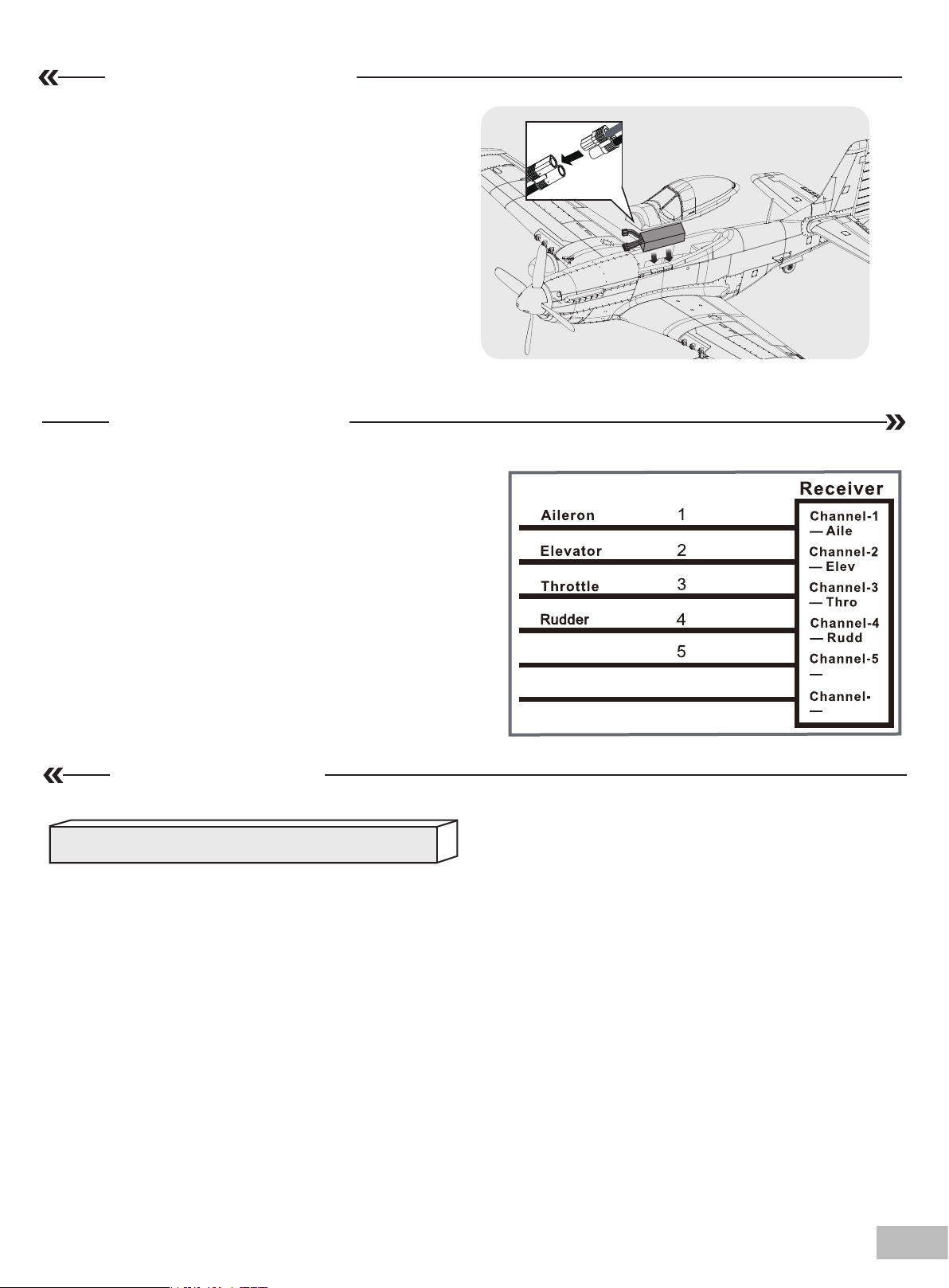
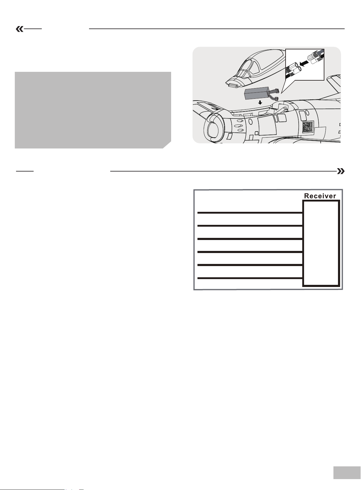
1. Remove the battery hatch.
2. Remove the hook and loop tape from the fuselage.
Apply the looped surface to the battery.
3. Install the battery into the fuselage- securing it with
the preinstalled battery straps.
Note: The weight of each battery may vary due to
different manufacturing techniques. Move the battery
fore or aft to achieve the optimal center of gravity.
Receiver diagram
The cables from the servo connector board should be
connected to your receiver in the order shown. Note that the
LEDs can be powered by any spare channel on the receiver.
Tuck the wire leads into the recessed cavity towards the
rear of the battery hatch.
Spare
Flap
5
6
Spare
6
Flap
Preflight check
Important ESC and model information
1. The ESC included with the model has a safe start. If the motor battery is connected to the ESC and the throttle stick is not in the low
throttle or off position, the motor will not start until the throttle stick is moved to the low throttle or off position. Once the throttle stick is
moved to the low throttle or off position, the motor will emit a series of beeps. Several beeps with the same tune means the ESC has
detected the cells of the battery. The count of the beeps equals the cells of the battery. The motor is now armed and will start when the
throttle is moved.
2. The motor and ESC come pre-connected and the motor rotation should be correct. If for any reason the motor is rotating in the wrong
direction, simply reverse two of the three motor wires to change the direction of rotation.
3. The motor has an optional brake setting. The ESC comes with brake switched off and we recommend that the model be flown with
the brake off. However, the brake could be accidentally switched on if the motor battery is connected to the ESC while the throttle stick
is set at full throttle. To switch the brake off, move the throttle stick to full throttle and plug in the motor battery. The motor will beep one
time. Move the throttle stick to low throttle or the off position. The motor is ready to run and the brake will be switched off.
4. Battery Selection and Installation. We recommend the
must be at least a
2200mAh 35C
4S 2200mAh 35C
Li-Po battery to fit the fuselage without changing the center of gravity significantly.
battery. Your battery should be approximately the same capacity, dimension and weight as the
4S 2200-2600mAh 35C
Li-Po battery. If using another battery, the battery
4S
07
Page 8
Preflight check
transmitter and model setup
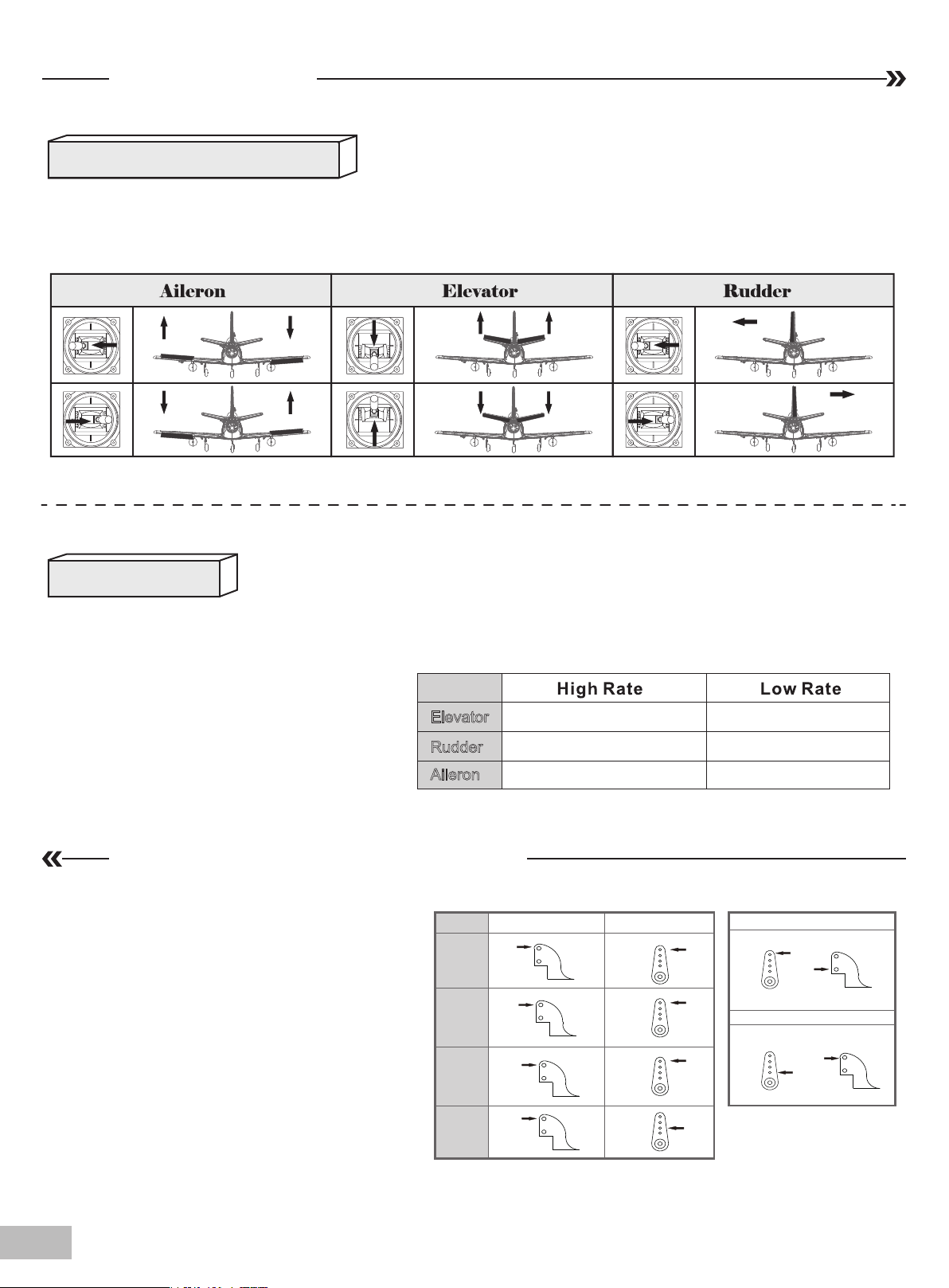
After assembly and prior to your first flight, make sure all control surfaces respond correctly to your transmitter by referring to the diagram below.
Control throws
The suggested control throw setting for the 64mm F-86 are as follows (dual rate setting):
Tips: The maiden flight should always be flown
using low rates, fly the aircraft until you are familiar with its characteristics prior to trying high
rates. Make sure the aircraft is flying at a decent
altitude and speed prior to using high rates, as
the aircraft will be sensitive to control inputs with
the larger control surface movements.
Elevator
Rudder
Aileron
12mm up / down
10mm left / right
14mm up / down
Control horn and servo arm settings
Horns
1. The table shows the factory settings for the
control horns and servo arms. Fly the aircraft at the
factory settings before making changes.
2. After flying, you may choose to adjust the linkage
positions for the desired control response.
ElevatorRudderAileronsFlap
Arms
10mm up / down
8mm left / right
12mm up / down
More control throw
Less control throw
08
Page 9
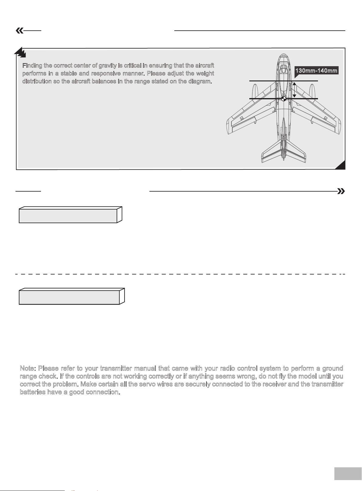
Finding the center of gravity
Finding the correct center of gravity is critical in ensuring that the aircraft
performs in a stable and responsive manner. Please adjust the weight
distribution so the aircraft balances in the range stated on the diagram.
• Depending on the capacity and weight of your choosen flight
batteries, move the battery forward or backward to adjust the
center of gravity.
• If you cannot obtain the recommended CG by moving the battery to a
suitable location, you can also install a counterweight to achieve correct
CG. However, with the recommended battery size, a counterweight is not
required. We recommend flying without unnecessary counterweight.
130mm-140mm
Before flying the model
Find a suitable flying site
Find a flying site clear of buildings, trees, power lines and other obstructions. Until you know how much area will be
required and have mastered flying your plane in confined spaces, choose a site which is at least the size of two to three
football fields - a flying field specifically for R/C planes is best. Never fly near people - especially children, who can
wander unpredictably.
Performing a range check
A radio range check should be performed prior to the first flight of the day. This test may assist you in detecting electronic
problems that may lead to a loss of control- problems such as low transmitter batteries, defective or damaged radio components or radio interference. This usually requires an assistant and should be done at the flying site.
Always turn your transmitter on first. Install a fully charged battery in the battery bay, then connect it to the ESC. In this
process, make sure that the throttle cut functionality is on, and that the throttle stick is secured in its lowest position- otherwise, the propeller/fan will engage and possibly cause bodily harm.
Note: Please refer to your transmitter manual that came with your radio control system to perform a ground
range check. If the controls are not working correctly or if anything seems wrong, do not fly the model until you
correct the problem. Make certain all the servo wires are securely connected to the receiver and the transmitter
batteries have a good connection.
09
Page 10
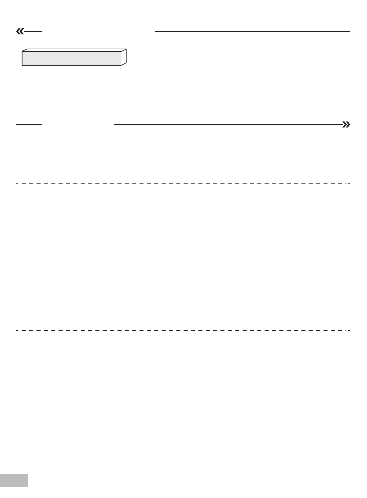
Before flying the model
Monitor your flight time
Monitor and limit your flight time using a timer (such as a stopwatch or on the transmitter, if available). As modern Lithium
Polymer batteries are not designed to discharge completely, when the battery runs low, the ESC will lower then completely
cut the power to the motors to protect the battery. Often (but not always) power can be briefly restored after the motor
cuts off by holding the throttle stick all the way down for a few seconds.To avoid an unexpected dead-stick landing on your
first flight,set your timer to a conservative 4 minutes. When your alarm sounds you should land right away.
Flying course
Take off
Point the aircraft into the wind while slowly applying power until the aircraft starts to track straight, use the rudder when
necessary. When the aircraft reaches takeoff speed, ease back on the elevator stick until the aircraft is climbing at a
constant rate without decelerating. Climbing at too steep of an angle at the relatively low speeds of a takeoff-climb may
result in an aerodynamic stall.
Flying
Always choose a wide-open space for flying your plane. It is ideal for you to fly at a sanctioned flying field. If you are not
flying at an approved site always avoid flying near houses, trees, wires and buildings. You should also be careful to avoid
flying in areas where there are many people, such as busy parks, schoolyards, or soccer fields. Consult laws and
ordinances before choosing a location to fly your aircraft. After takeoff, gain some altitude. Climb to a safe height before
trying technical manoeuvres.
Landing
Land the aircraft when you start to feel sluggish motor response. If using a transmitter with a timer, set the timer so you
have enough flight time to make several landing approaches.The model’s three point landing gear allows the model to land
on hard surfaces. Align model directly into the wind and fly down to the ground. Fly the airplane down to the ground using
1/4-1/3 throttle to keep enough energy for proper flare. Before the model touches down, always fully decrease the throttle
to avoid damaging the propeller or other components. The key to a great landing is to manage the power and elevator all
the way to the ground and set down lightly on the main landing gear. With some practice, you will be able to set the aircraft
gently on its main gear and hold it that way until the speed reduces enough where the nose wheel (tricycle landing gear
aircraft) or tail wheel (tail draggers) settles onto the ground.
Maintenance
Repairs to the foam should be made with foam safe adhesives such as hot glue, foam safe CA, and 5min epoxy. When
parts are not repairable, see the spare parts lst for ordering by item number.Always check to make sure all screws on the
aircraft are tightened. Pay special attention to make sure the spinner is firmly in place before every flight.
10
Page 11
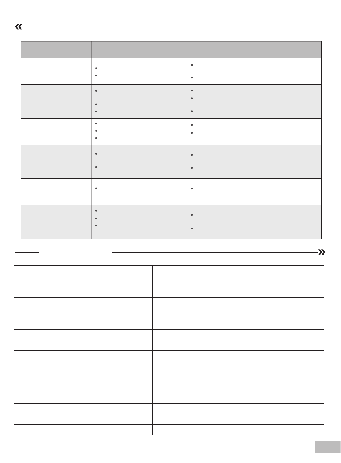
Troubleshooting
Problem Possible Cause Solution
Aircraft will not respond to
the throttle but responds to
other controls.
Excessive vibration or
propeller noise.
Reduced flight time or
aircraft underpowered.
Control surfaces
unresponsive or sluggish.
Controls reversed.
Motor loses power
Motor power pulses then
motor loses power.
ESC is not armed.
Throttle channel is reversed.
Damaged spinner, propeller,
motor or motor mount.
Loose propeller and spinner parts.
Propellor installed backwards.
Flight battery charge is low.
Propeller installed backward.
Flight battery damaged.
Control surface, control horn,
linkage or servo damage.
Wire damaged or connections
loose.
Channels are reversed in the
transmitter.
Damage to motor, or battery.
Loss of power to aircraft.
ESC uses default soft Low Voltage
Cutoff(LVC).
Lower throttle stick and throttle trim to lowest
settings.
Reverse throttle channel on transmitter.
Replace damaged parts.
Tighten parts for propeller adapter, propeller
and spinner.
Remove and install propeller correctly.
Completely recharge flight battery.
Replace flight battery and follow flight battery
instructions.
Replace or repair damaged parts and adjust
controls.
Do a check of connections for loose wiring.
Do the control direction test and adjust controls for
aircraft and transmitter.
Do a check of batteries, transmitter, receiver, ESC,
motor and wiring for damage(replace as needed).
Land aircraft immediately and recharge flight battery.
AHAY101
AHAY102
AHAY103
AHAY104
AHAY105
AHAY106
AHAY107
AHAY108
AHAY109
AHAY110
AHAY111
AHAY112
AHAY113
AHAY114
AHAY115
Spare parts list
Fuselage
Main wing set
Horizontal stabilizer
Vertical Stabilizer
Canopy
Wing bolt plastic set
Wing Pipe
Control horn
Front landing gear
Main landing gear set
Auxiliary fuel tank
Linkage Rods
Sticker
Screw Set
Steering wire
AHAY117
AH64MM12B
AHKV3150
AHESC40A-2
AH9GP
AH9GR
Landing gear base
64mm Ducted Fan(12-blade)
Motor 2840-KV3150
40A ESC
9g servo positive
9g servo reverse
AHAY116
Aluminum sleeve
11
Page 12

重要提示:
1. 在组装、调整及飞行前请务必认真阅读产品说明书以熟知产品的特性。请严格按照说明书提示进行飞机的组装、
调整及飞行。
2. 模型不是玩具,具有一定的危险性,操作者需要具备一定的飞行经验,初学者请在专业人士指导下操作。
3. 禁止十四岁以下儿童在任何情况下操作、飞行。
警告
★作为用户,您对本产品的安全操作和维护负全部责任。请始终严格遵照产品指导说明及安全警告操作本产品及其相关
配置(例如遥控器、充电器、电池等)。
★本产品由无线电遥控器控制,在飞行过程中,可能会受到外界强信号源干扰而导致失控,甚至坠机,因此,在飞行过
程中务必始终与飞机保持一定的安全距离,避免意外碰撞、受伤。
★请勿随意暴露置放模型飞机的电子产品,尤其是电池,存放时请务必保证周围三米之内无易燃易爆物体。
★在任何情况下,都务必保证油门杆处于起始位、发射机处于通电状态时,才能连接模型飞机内部的动力电池。
★在任何情况下,都不要尝试用手去回收飞行中的模型飞机,必须要等模型飞机降落停稳以后,再进行回收。
★请勿在公路、人群、高压线密集区、机场附近及其它法律法规明确禁止飞行的场合飞行。
★请勿在雷雨、大风、大雪或者其它恶劣气象环境下飞行。
★请勿将相关化工类产品、零部件、电子部件等置于儿童可触及的范围。
★请勿将本产品尤其是未经特别设计和保护的电子件暴漏于潮湿的环境中,以免造成损坏。
★请勿将本品任意处置于口中,以免造成人身伤亡。
★请勿在发射机电池低电量的情况下操纵模型飞机。
★请勿在配件未充分冷却的情况下触碰或移动。
★请勿使用化学制剂擦拭清洁本产品。
★务必保证飞机在整个操作过程中始终在视线范围和遥控控制距离内。
★务必保证在拆卸飞机之前移除电池。
★务必保证所使用的电池是满电状态。
★务必保证所使用的所有线束完好无损。
飞行前准备
1. 开箱检查包装内物品是否有损坏或遗漏。
2. 通读此飞机说明书以及其相关配置说明书(如遥控器、电池和充电器)。
3. 确保遥控器和使用的电池都是满电状态(请严格遵从配件原厂家说明书)。
4. 遥控器设置(请严格遵从遥控器厂家的说明书)。
5. 严格遵从本说明书指导组装飞机,确保螺丝、卡扣、夹头、插销等紧固件全部安装到位,舵角摇臂连接可靠。(暂
不安装螺旋桨)。
6. 安装满电状态的电池,并通过挪动电池在电池舱里的前后位置,调整飞机重心(CG)至说明书推荐位置。
7. 通电测试确保所有的操纵钢丝活动自如。
8. 通电测试确保所有的舵面正确响应遥控器输入指令。
9. 根据所需调整舵面行程(首飞推荐使用出厂设置行程)。
10. 桨机安装螺旋桨,确保螺旋桨组件安装到位,且转动方向正确。
11. 寻找一个安全空旷远离建筑和人群的场地,根据场地实际情况,做具体飞行计划。
12
Page 13
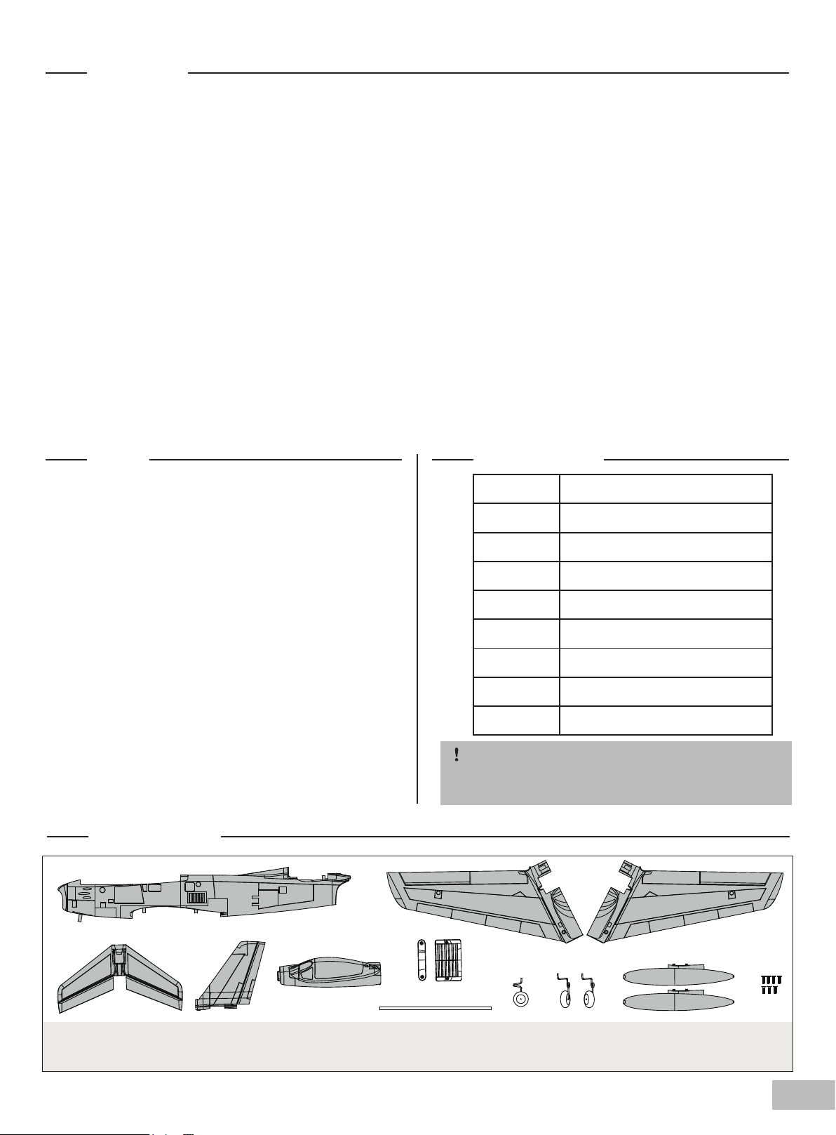
飞机简介
F-86 战斗机,绰号:佩刀,是二战后美国北美航空公司研制的第一代单座单发后掠翼亚音速喷气式战斗机,用于空战,拦截与轰炸。
它可以在高速混战中对抗苏联的后掠翼 MiG-15. F-86 是第一架俯冲时超音速以及第一架装备空对空飞弹的战机。它是美国早期设计
的最为成功的喷气式战斗机代表作。除了大量的次型外,它还衍生出海军型 FJ 战斗机。
人们总是乐此不疲地争论,Arrows Hobby 涵道机 MiG-29 和 F-15 哪个是“王道”。Arrows Hobby 的工程师团队深受鼓舞,并“周
到”地带来第三个选项,64mmF-86。Arrows Hobby 64mm F-86 以其高速性能下的控制性以及低速飞行的机动性和稳定性毫无疑义
地成为“王道”机型的强劲角逐者。
64mm F-86 配备 64mm12 叶涵道组、2840-KV3150 无刷电机、40A 无刷电调,其搭配 4S 电池,可给飞行提供澎湃的动力,以
完成横滚、俯冲等缠斗战斗动作,以及绕圈、翻滚、倒飞等特技动作。类似涡轮动力喷气机的高仿真声浪一秒将飞场变成战场。
F-86 采用 EPO泡沫材料制作,机长 820mm,翼展 860mm。机体外形轮廓及表面刻线都高度精准像真。F-86 采用螺丝组装结构,
在保证飞行重量可控的同时,有效提升机体强度和缩短拆装时间⸺快拆快装结构起落架便利草地手动起飞和腹部降落。机体和翼面
大量使用碳纤管强化,使其即便在剧烈的飞行动作下,也不易弯曲、变形。此外,高辨识度的经典涂装,经过特殊的水性漆处理,使
得整架飞机闪耀着金属冷光。
“佩刀”,Arrows Hobby“王道”战机的第三个选项,一款睥睨飞场的传奇战斗机,你还在等什么?
特征:
• 动力配置:64mm12 叶涵道组、2840-KV3150 无刷电机、
40A 无刷电调、9g 舵机
• 高还原度动态和静态细节,嵌板线、双可抛油箱、襟翼等
• 可转向的前起落架有效增强地面机动性
• 高品质耐磨轮胎
• 预安装球头舵角,增大行程,精准操作
• 大量使用碳纤管强化的机体和翼面
• 优秀的机动性能和低速飞行性能
目录
飞行前准备
飞机简介
目录
产品包装清单
产品基本参数
组装过程
电池安装
接收机连接示意图
重心
重要产品相关信息
电调说明
遥控器设置
舵面测试
舵角和舵机摇臂安装
舵面行程
故障检修指导
配件列表
.............................................................
.................................................................
.......................................................................
..........................................................
..........................................................
................................................................
................................................................
...................................................
.......................................................................
...................................................
.................................................................
..............................................................
.................................................................
...............................................
.................................................................
..........................................................
.................................................................
产品包装清单
12
13
13
13
13
14
17
17
18
18
18
18
19
20
20
21
21
产品基本参数
翼展
机身长
飞行重量
电机
翼载荷
翼面积
电调
舵机
推荐电池
注意:此处各项参数,均是使用本公司配件测试得
出,如果使用他厂配件,会有所差异。使用他厂配
件时所产生的问题,我司将无法给予技术支持。
860mm(33.8in)
820mm(32.3in)
~ 1050g
2840-KV3150
69g/dm²(0.15oz/in²)
15.2dm²(235sq.in)
40A
9g Servo x 8
4S 2200-2600mAh 35C
A. B.
C. D. E. F.
A: 机身
B: 主翼
C: 平尾
D: 垂尾
E: 座舱
F: 主翼固锁胶件 H: 前起落架
G.
G: 主翼对接管
K. H. I. J.
I: 主起落架组 K: 螺丝组
J: 油箱组 (7-HKM3x10mm)
13
Page 14
组装过程
主翼安装
1.如图所示,将主翼安装至主翼对接管。 2.如图所示,将舵机线穿入机身到座舱内,用所附主翼
固锁胶件和螺丝固定主翼至机身。安装完主翼连接1通
和6通2Y线。
平尾安装
1.如图所示,将平尾舵机线连接至机身尾部延长线,平
尾安装至机身尾部槽位。
14
Page 15
组装过程
垂尾安装
1.如图所示,将垂尾舵机线连接至机身尾部舵机延长线,
垂尾安装至机身尾部相对应的凹槽,用所附螺丝固定。
起落架安装
1. 如图所示,将前起落架安装至机头底部槽位,用所附
螺丝固定。
15
Page 16
组装过程
2.将主起落架插入主翼起落架槽中,并旋转90度以锁定
起落架位置。(注意:主起落架区分左右)
油箱安装
1. 如图所示,将两侧油箱安装至主翼底部槽位。
16
Page 17
电池安装
如图所示,安装厂家推荐型号电池至电池舱,使用所附魔
术带或魔术贴固定。
注意:
1. 电池与电调连接前,务必确定油门杆处于低位。
2. 启动油门前,务必确定没有任何人或物体处于螺旋
桨的转动直径以内。
3. 由于不同电池厂家生产的电池重量有轻微差异,需
要调整电池在舱内的前后位置来平衡飞机的重心位置。
接收机连接示意图
以 Futaba 遥控器为例,请按照图示顺序一一连接接收机通
道,其他通道可接入襟翼信号线或 LED 灯信号线 , 随后妥善
固定接收机。
副翼
平尾
油门
垂尾
起落架
其他通道
1
2
3
4
5
6
Channel-1
—Aile
Channel-2
—Elev
Channel-3
—Thro
Channel-4
—Rudd
Channel-5
—Gear
Channel-6
—Spare
17
Page 18
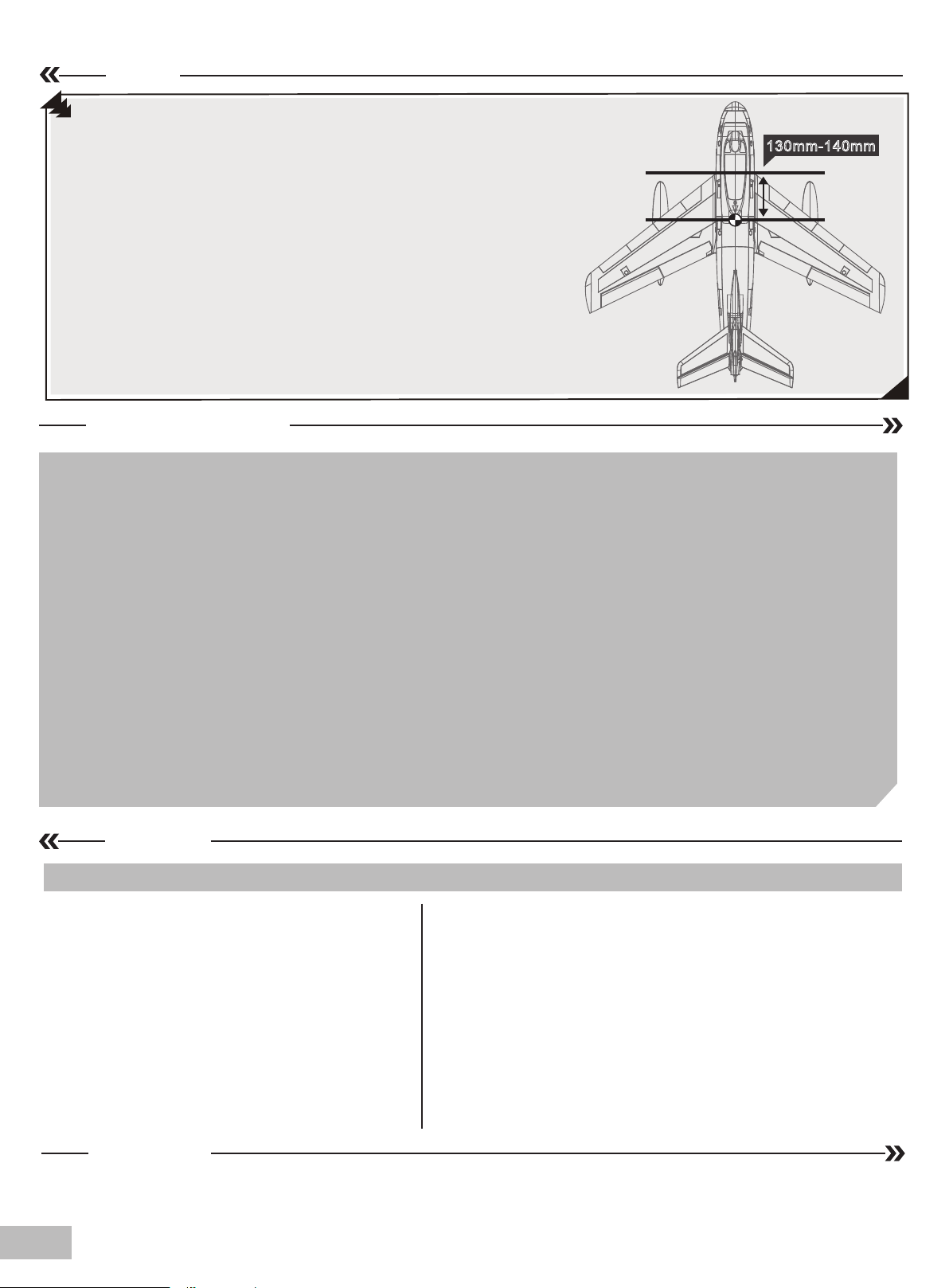
重心
130mm-140mm
本产品的重心在机翼前缘向后 130-140mm 的位置。玩家
需要通过移动电池在电池舱里的前后位置或者使用配重块
来调整重心。请务必确保,在调整飞机重心的时候,飞机
处于组装完毕待飞的状态。
重要产品相关信息
1. 本产品随附的电调处在安全启动模式。安全启动模式,意即如果电机、电池已连接至电调,但油门杆不在低油门
位置或关闭位置,电机不会启动,只有将油门杆移至低油门位置或关闭位置,电机才会启动。油门杆移至低油门位
置或关闭位置时,电机将发出一系列哔声。几声相同的哔声表示电调已检测到电池。哔声的数量等于电池的节数。
此时,电机已准备就绪,并将随着油门移动开始启动。
2. 电机和电调已预连接,需要观察电机转动方向是否正确,如方向不正确,只需换插三条电机与电调连接线中的任
意两条,即可改变电机转动方向。
3. 电机具有刹车设置(可选项)。由于电调是刹车关闭状态,我们推荐电机也保持刹车关闭状态。此外,请注意,当
油门杆处在全油门位置上时,如果将电机、电池连接到电调,则可能会意外打开刹车。如要关闭刹车,需将油门杆
移至全油门位置,并插上电机电池,电机此时会发出一声哔响,再将油门杆移至低油门位置或关闭位置,则电机已
准备就绪,且刹车将被关闭。
4. 电池的选择和安装。我们推荐使用 4S 2200-2600mAh 35C 锂电池。如果使用其他电池,电池的容量不能低于推
荐电池容量,且电池的尺寸和重量应与推荐电池相同,以保证适配机身电池舱,且不会显著改变重心。
电调说明
注意:为了让电调适应你的遥控器油门行程,在首次使用本电调或更换其他遥控器使用时,均应重新设定油门行程。
油门行程设定说明:
1. 开启遥控器,将油门打到最高点;
2. 将电调接上电池,等待 2 秒;
3. “哔 - 哔 -” 油门最高点,确认声音;
4. 将油门推到最低等待 1 秒;
5.N 声短鸣音表示锂电节数;
6. “哔 - ” 油门最低点,确认声音;
7. 系统准备就绪可以起飞。
正常使用开机过程说明 :
1. 开启遥控器,将油门打到最低点;
2. 电调接上电池,鸣叫提示音符 “ 123”,表示上电正常;
3. 发出 N 声短鸣音,表示锂电池节数;
4. 自检 OK,发出长鸣音 “哔——” 系统准备就绪;
5. 推油门可随时起飞。
18
遥控器设置
请参考遥控器原厂家说明书。
Page 19
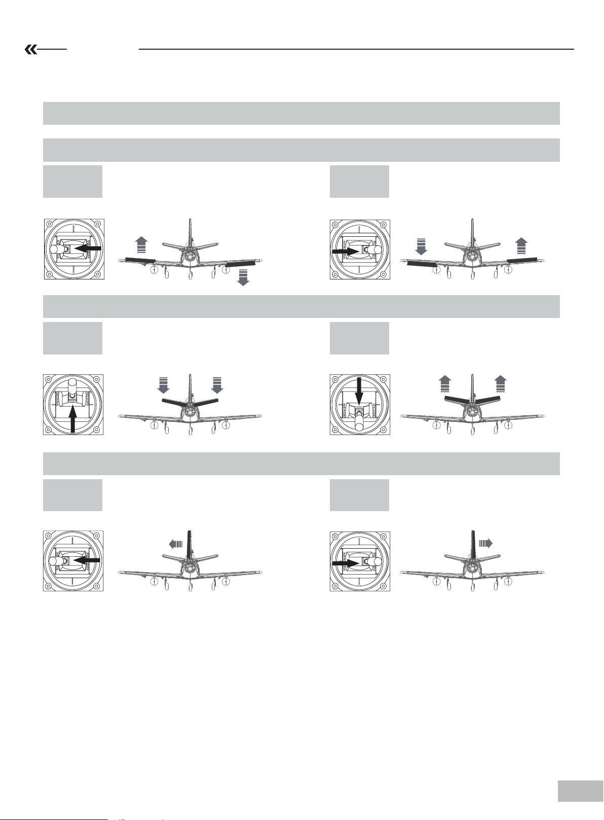
舵面测试
在计划飞行之前,需要使用遥控器测试每个舵面的工作情况,确保摇杆动作与各个舵面动作的对应关系如下图所示 :
注意:在舵面调试中,请务必将油门摇置于最低位,并将桨拆下,以免电机意外启动发生事故。
副翼
副翼摇杆
向左运动
升降舵
升降摇杆
向上运动
方向舵
副翼摇杆
向右运动
升降摇杆
向下运动
方向摇杆
向左运动
方向摇杆
向右运动
19
Page 20
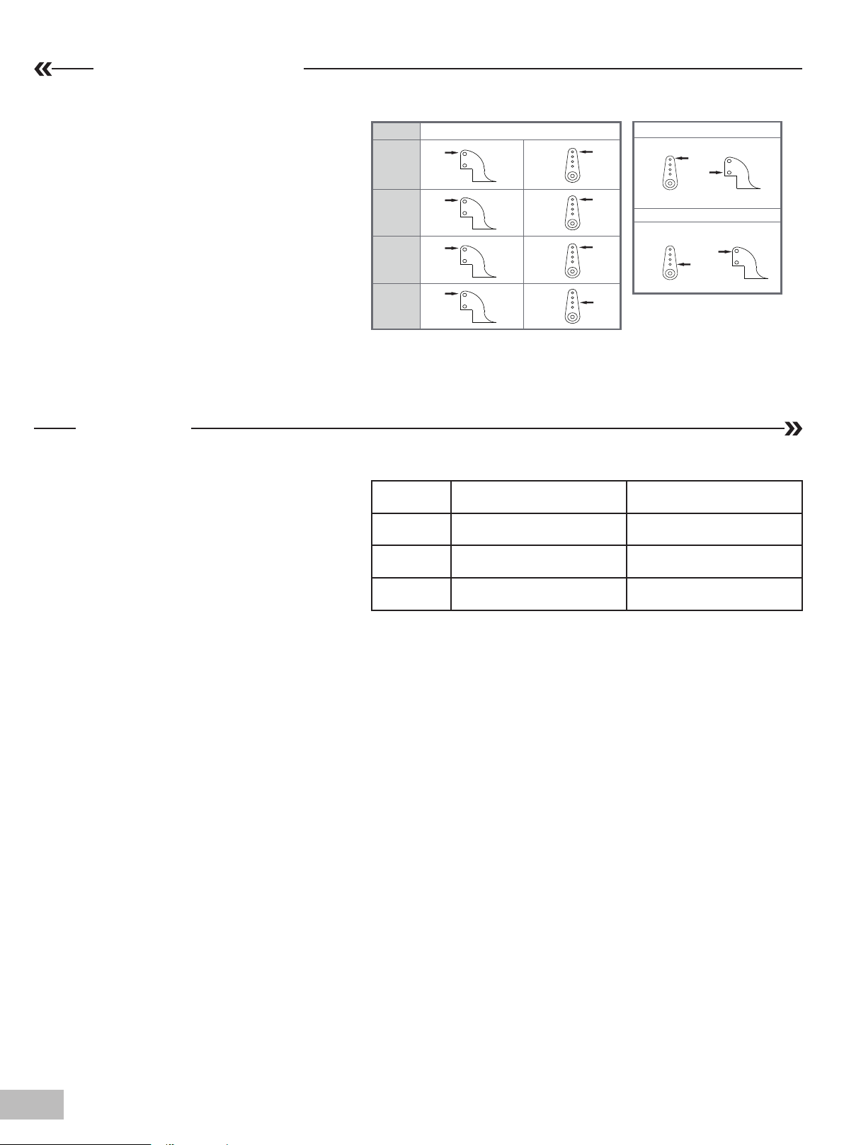
舵角和舵机摇臂安装
图示是出厂设置,首飞建议直接使用出厂
设置,完成首飞以后,根据个人情况以及
对模型飞机的熟知程度自行调整。
舵面行程
本产品舵面行程参数如右图所示:
请注意,舵量越大,模型飞机的动作响应
越快,动作幅度越大。首飞建议使用小舵
量。然后根据个人情况以及对模型飞机的
熟知程度调整舵量。
平尾
垂尾
副翼
襟翼
升降舵
方向舵
副翼舵
舵角 摇臂
大 小
12mm 上 / 下 10mm 上 / 下
10mm 左 / 右 8mm 左 / 右
14mm 上 / 下 12mm 上 / 下
大舵面
小舵面
20
Page 21
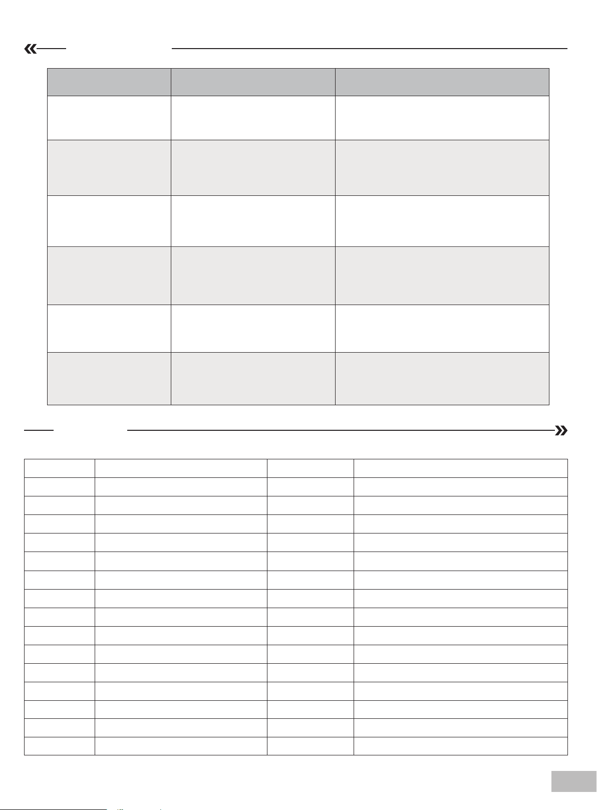
故障检修指导
问题 问题原因 解决方式
油门推杆无响应,但舵机
有响应
桨的噪音过大或者震动过大
飞行时间变短,飞机无力
飞舵面不动,或者动作响
应较慢
舵面反向 ——遥控器发射机通道反向
电机无力
——电调未连接电机
——油门通道反向
——桨罩、桨、电机、电机架坏了
——桨或者桨罩的小部件松动了
——桨装反了
——电池电量低
——桨装反了
——电池坏了
——舵面、舵角、连接杆、舵机坏了
——连接线坏了或者接头松了
——电机或电池坏了
——电调用了不合适的低压保护装置
——降低油门推杆和油门微调设定
——反过来重新装油门通道
——更换损坏的配件
——把桨、桨夹和桨罩的小部件拧紧
——反过来重新装桨
——重新给电池充电
——依照电池说明书更换新的电池
——更换或者维修坏了的配件
——检查所有连接线,确保所有接头无松动现象
——检查通道控制(舵面)方向,调试飞机舵面
和遥控器的舵面控制杆
——检查电池、发射机、接收机、电调、电机是
否有损坏(如有,请及时更换)
——立刻操控飞机降落,重新给电池充电
配件列表
AHAY101
AHAY102
AHAY103
AHAY104
AHAY105
AHAY106
AHAY107
AHAY108
AHAY109
AHAY110
AHAY111
AHAY112
AHAY113
AHAY114
机身
主翼
平尾
垂尾
座舱
主翼固锁胶件
主翼对接管
舵角组
前起落架
主起落架组
油箱组
连接钢丝
贴纸
螺丝组
AHAY117
AH64MM12B
AHKV3150
AHESC40A-2
AH9GP
AH9GR
主起落架底座
64mm 涵道 (12 叶 )
电机 2840-KV3150
40A 电调
9g 塑胶正向舵机
9g 塑胶反向舵机
AHAY115
AHAY116
前起落架转向钢丝
前起落架铝套
21
Page 22

 Loading...