

Page 1
Maint ena nce
• Check t hat t he br ack et is s ecure and sa fe to u se at r egu lar intervals (at l eas t eve ry three months ).
• Pleas e con tac t you r distributor i f you h ave a ny qu estions.
INSTALLATION MANUAL
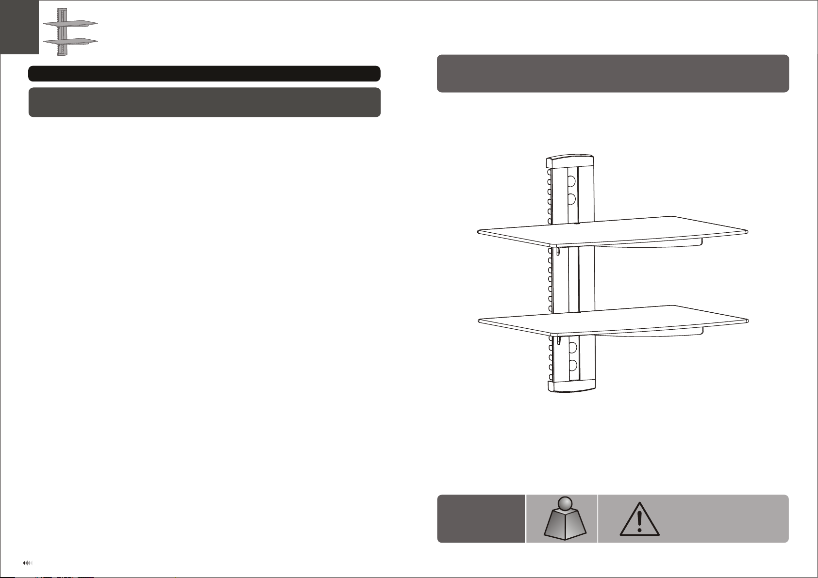
DVD Wall Mount
CA UTI ON : DO NOT EXCE ED
DV D-212
8kg x2
8kg x2
(17 .6lbs x2)
(17 .6lbs x2)
RATE D
RATE D
RATE D LIS TED WE IGH T. SERI OUS
INJ URY OR P ROP ERTY DAMA GE
MAY OCCUR!
ISSUED: APR. 2013
7
Page 2
NOTE: Rea d the entire instr uction manual be fore you st art ins tallati on and assembly.
WARNING
• Do not begin the installation until you have read and understood all the instructions
and warnings contained in this installation sheet. If you have any questions
regarding any of the instructions or warnings, please contact your local distributor.
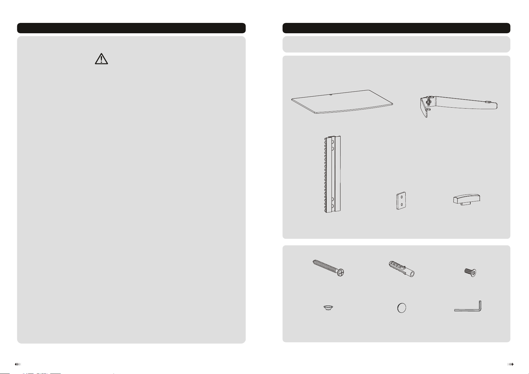
Component Checklist
IMPORTANT: E nsu re th at you have r ece ive d all p arts acco rdi ng to t he co mpo nent chec kli st pr ior t o install ing . If
any p art s are m iss ing o r faulty, co nta ct the dist rib uto r for a r eplacem ent .
• This mounting bracket was designed to be installed and utilised ONLY as
specified in this manual. Improper installation of this product may cause damage
or serious injury.
• This product should only be installed by someone with good mechanical ability
who has basic building experience and fully understands this manual.
• Make sure that the supporting surface will safely support the combined weight of
the equipment and all attached hardware and components.
• If mounting to wood wall studs, make sure that mounting screws are anchored
into the center of the studs. The use of a stud finder is highly recommended.
• Always use an assistant or mechanical lifting equipment to safely lift and position
the equipment.
• Tighten screws firmly, but do not over tighten. Over tightening can cause damage
to the items, This greatly reduces their holding power.
• This product is intended for indoor use only. Using this product outdoors could
lead to product failure and personal injury.
Package P
glass s hel f(x 2)
wall pl ate (x1 )
C
ST5.5 x50 ( x4)
P-A
A
conne ct pi ece (x2 )
D
concr ete a nch or (x 4)
P-B
glass h old er (x 2)
B
decor ati ve co ver (x2)
M5x10 ( x6)
E
P-C
plast ic bu sh( x2)
P-D
plast ic ca p(x 4)
P-E
3mm Allen key (x1)
P-F
21
Page 3
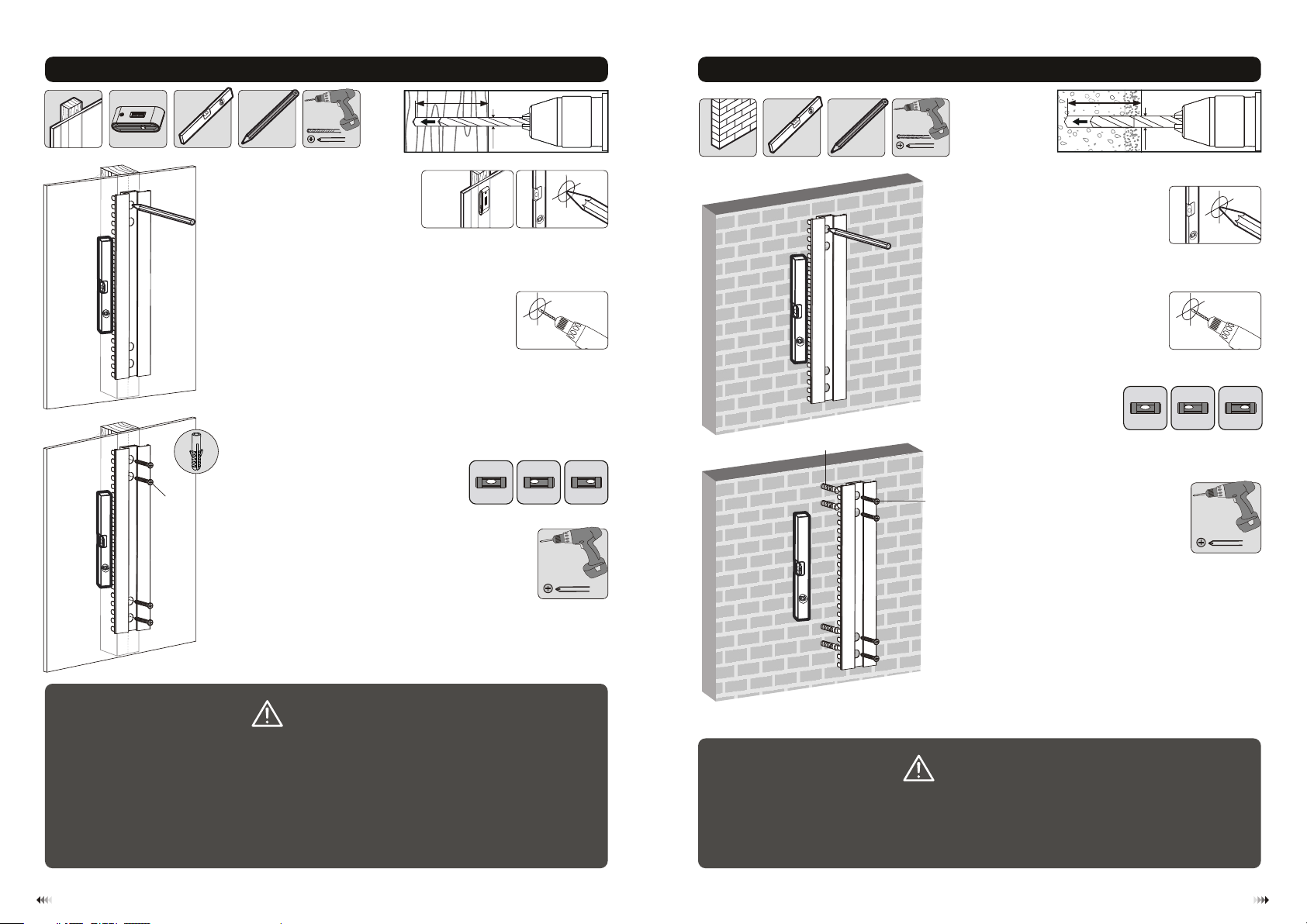
1a. For Wood Stud Wall Mounting
55mm
55mm
50mm
2.2"( )
(2.2")
(2")
ø 4mm
(ø 5/32")
1b. For Solid Brick and Concrete Mounting
60mm
60mm
55mm
2.4"( )
(2.4")
(2.2")
ø 8mm
(ø 5/16")
P-A
XX
1
Find an d mar k the e xac t
locat ion o f mou nti ng ho les.
√
2
3
Drill pilot holes
X X
Screw the wall
plate onto
the wall
P-B
P-A
1
Mark th e exa ct
locat ion o f mou nti ng
2
Drill pilot holes
√
holes .
X X
Screw the wall
plate onto the
wall
WARNING
• Make sure that mounting screws are anchored into the center of the studs. The use of a stud
finder is highly recommended.
• Installers are responsible to provide hardware for other types of mounting situations.
• Installers must verify that the supporting surface will safely support the combined weight of the
equipment and all attached hardware and components.
WARNING
Installers must verify that the supporting surface will safely support the combined weight of
the equipment and all attached hardware and components.
43
Page 4
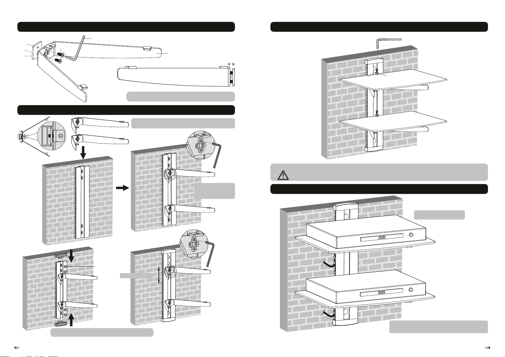
2.Installing the Glass Holders
P-F
P-C
D
4. Installing the Glass Shelves
P-F
B
3mm
3. Installing the Glass Holders
E
P-E
Tig hte n scr ews to allow for 3m m spa cin g.
Inser t the g las s hol ders at a desired p osi tio n alo ng
the wal l pla te ra il.
P-C
Tig hte n all s crews
to secu re th e gla ss
holde rs.
P-C
adjus t hei ght
P-F
P-F
P-C
Attac h the g las s she lves to the glass h old ers u sin g the screws and th e pla sti c bus hes.
Tig hten all screws b ut do n ot ov er ti ghten.
P-D
5. Cable Management 5. Cable Management
(DVD ar e not i ncl ude d)
Insta ll th e dec ora tive covers and t he pl ast ic ca ps.
Place D VD ge ntl y on th e mounted holde r.
Place t he gl ass g ent ly on the mounted h old ers .
Run the c abl e thr oug h the cable clips .
Run the c abl es th rou gh the cable clip s.
65
 Loading...