

Page 1

LCD Keypad
Operating &
ProgrammingGuide
12
Arrowhead Alarm Products Ltd
Proudly Designed and Manufactured in New Zealand
1
Page 2

CONTENTS Page No.
INTRODUCTION 3
Introduction to the LCD Keypad 3
KEYPAD “DIP” SWITCH SETTINGS 4
Setting the keypad address 4
Setting the panel type 4
DESCRIPTION OF KEYPAD BUTTON OPERATION 5
What each keypad button does 5
LOCAL KEYPAD FUNCTIONS 6
Adjusting the LCD backlighting 6
Adjusting the keypad LED backlighting 6
Adjusting the keypad buzzer tone (volume) 6
Accessing the Alarm Event Memory Mode 6
LOCAL EDIT PROGRAM MODE 7
Introduction to local edit program mode 7
Accessing Local Edit Mode 7
Local Edit Mode Program addresses 7
Changing the Zone Names 7
Text selection chart 8
Changing the Panel Name displayed on the LCD 9
Changing the Character used to identify Areas 9
Resetting text to defaults or last saved version 9
Copying edited text to other LCD keypads 10
Exiting Local Edit Mode 10
OWNERS DETAILS 11
Record of Text changes 11
OWNERS DETAILS
INSTALLERS NAME:
INSTALLERS CONTACT PH #:
TEXT EDIT CHANGES
Control Panel Name :
AREA A Character (Default A)
AREA B Character (Default B)
AREA C Character (Default C)
AREA D Character (Default D)
ZONE DESCRIPTIONS:
Zone # 1 Zone # 2
Zone # 3 Zone # 4
Zone # 5 Zone # 6
Zone # 7 Zone # 8
Zone # 9 Zone # 10
Zone # 11 Zone # 12
Zone # 13 Zone # 14
Zone # 15 Zone # 16
Zone # 17 Zone # 18
Zone # 19 Zone # 20
Zone # 21 Zone # 22
Zone # 23 Zone # 24
Zone # 25 Zone # 26
Zone # 27 Zone # 28
Zone # 29 Zone # 30
Zone # 31 Zone # 32
Zone # 33 Zone # 34
Zone # 35 Zone # 36
Zone # 37 Zone # 38
Zone # 39 Zone # 40
Zone # 41 Zone # 42
Zone # 43 Zone # 44
Zone # 45 Zone # 46
Zone # 47 Zone # 48
Zone # 49 Zone # 50
Zone # 51 Zone # 52
Zone # 53 Zone # 54
Zone # 55 Zone # 56
Zone # 57 Zone # 58
Zone # 59 Zone # 60
Zone # 61 Zone # 62
Zone # 63 Zone # 64
2
11
Page 3

*Copying the text to other LCD keypads connected to the panel*
If more than one LCD keypad is connected to the panel, it is possible to copy the edited Text
from one LCD keypad to any other keypads connected to the same panel.
While in “Local Edit Mode” at the keypad with the edited text, if you press “Control” followed
within 2 seconds by “3”, the text in your keypad will be transferred to all other LCD keypads
connected to the panel.
NOTE: Each LCD keypad MUST be set to a different address for this function to work correctly.
*Exiting Local Edit Program Mode*
Press “PROGRAM” then “ENTER” (the LCD keypad will leave Local Edit Mode and return to
Idle Mode).
Introduction
Thank you for purchasing the Arrowhead LCD (liquid crystal display)
keypad.
The LCD keypad uses two lines of 16 characters to display full alpha numeric text.
This keypad has been designed to keep the day to day operation as simple as possible so
that all users will feel comfortable using the alarm system. To simplify normal daily operations
we have provided many clearly identified keypad buttons that are dedicated to single tasks.
The LCD keypad is also a very powerful diagnostic tool allowing easy access to the alarm
systems’ event memory. The event memory stores multiple alarm activity events. All of the
events are logged with the time and date they occurred and displayed via the LCD keypad.
The LCD keypad can be customized to suit the particular needs of the end user and this
manual details how these changes can be made.
The following pages explain how to use the many special features of this keypad as well as
how to program the customizable features.
READY
TROUBLE
BYPASS
SYSTEM
PowerWave 16
01/01/03 10:30
AREA
A
B
C
D
10
¡ ARM MEMORY£ PANIC¢
STAY¤
BYPASS
CONTROL
PROGRAM
1
4ghi
7pqr 8stu 9vwx
0yz
2abc 3def
5jkl 6mno
- ENTER -
Figure 1
3
Page 4
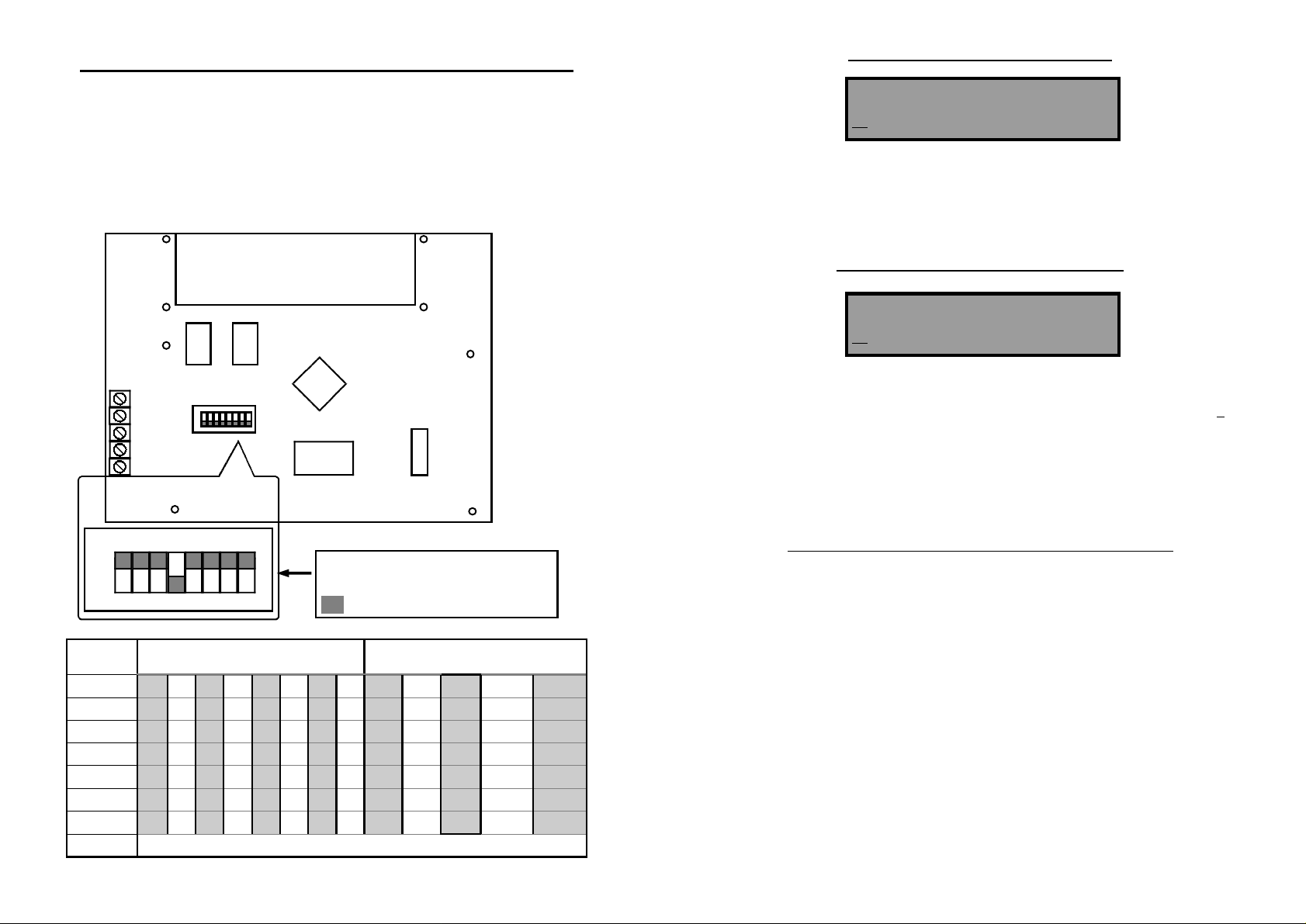
Setting the Keypad Address & Panel Type
Each Keypad Must have a different address setting before applying power. If there is only
one keypad used on the system then the default setting of keypad #1 is OK. The switches
are only read on power-up so they must be set before applying power. Switches 1-3 determine the keypad address. Switches 4-7 are used to set the keypad for the type of alarm
panel it will used on (see table below for details). Switch # 8 is un-used.
NOTE: There are two PW64 settings, the first works with software versions V1.01 panels and
the second with V1.04 and above.
Rear of Keypad PCB
POS
NEG
CLK
DAT
LINE
8 7 6 5 4 3 2 1
Address shown=KP 1
Panel type =PW8 (Alert 8D)
ON
Switch #
¤
1
2 off off ON ON off off ON ON - - - - 3 off off off off ON ON ON ON - - - - 4 - - - - - - - - off off off off off
5 - - - - - - - - off ON off ON off
6 - - - - - - - - off off ON ON off
7 - - - - - - - - off off off off ON
8
KEYPAD ADDRESS NUMBER
1 2 3 4 5 6 7 8
off ON off ON off ON off ON - - - - -
= Switch position
PW4 PW8 PW16 PW64(101) PW64(104)
Switch 8 is un-used
PANEL TYPE SETTINGS
*Changing the Keypad Panel Name*
Name <A..Z>
PowerWave 16D
When you enter in [PROG]-[999]-[ENTER] the display will look like the example above (the
actual name will depend on the settings of switches 4-7 as per the chart on page 4). You may
enter any name you wish up to 16 characters in length (using the same method as described
on the previous pages for zone names). This name is displayed at the keypad in Idle mode.
When you are happy with the changes Press “ENTER” to save.
*Changing the Keypad Area Character*
Areas <A..Z>
ABCDEFGHIJKLMNOP
When you enter in [PROG]-[998]-[ENTER] the display will look like the example above. You
may edit the single character Area Names at this address starting at Area “A” (first left-hand
position). The keypad allows for up to 16 partitions or areas but the actual number of areas
supported will be dependant upon the panel type set. The first character (in this case the ”A”)
is the identifier used to show the status of the first Partition. The second position (in this case
the “B”) is the identifier used to show the status of the second partition.
If you preferred to have the first partition shown as Area “1” and not “A” then you can change
it here using the same method as used previously. With the cursor underneath the letter “A”,
Press the “1” button four times until the character in the first slot shows “1”.
When you are happy with the changes Press the “ENTER” button to save the changes.
*Resetting the Text to Default or Last Saved Setting*
While in “Local Edit Mode” there are two special functions that can be performed at any of
the addresses 1-64, 998 & 999. They are “Return to Default Text” or “Return to Previ-
ously Saved Text”.
For Example, to Return the Zone 1 text back to Defaults;
If during the programming of Zone 1 text [PROG]-[1]-[ENTER] you wished to return back to
the default text, simply Press “Control” followed within 2 seconds by “2” and the text will
return to the default settings.
If you wished to return to the last saved version of the text simply Press “Control” followed
within 2 seconds by “1” and the last saved text for zone one will appear.
NOTE: If the last saved version of text for Zone 1 was in fact the default setting, then pressing “Control” then “1” will return the default text anyway.
4
9
Page 5

Once you have selected the desired font size you can now proceed to change the text for
Zone 1.
The following table shows the English Characters that can be selected by each numeric button.
▼Button # 1st Press 2nd Press 3rd Press 4th Press
1 * (‘) # (<) = (>) 1
2 A (a) B (b) C (c) 2
3 D (d) E (e) F (f) 3
4 G (g) H (h) I (i) 4
5 J (j) K (k) L (l) 5
6 M (m) N (n) O (o) 6
7 P (p) Q (q) R (r) 7
8 S (s) T (t) U (u) 8
9 V (v) W (w) X (x) 9
0 Blank Y (y) Z (z) 0
The lower case options are shown in ( ).
There are four different selections per button. By pressing the button once, a character will
appear in the display (see “1st press” column below) . Pressing the same button again will
cause the display to change to the next character in the sequence (see “2nd press” column).
After you have pressed the same button four times the next press (5th) will cause the display
to wrap back to the beginning.
Once you have selected the first character, Press the “PANIC” (right arrow) button to move
the cursor one position to the right.
Now select the second character and move the cursor to the right repeating the process until
all of the text is completed (Remember that there are a maximum of 16 characters per program address).
If you make a mistake use the “ARM” (left arrow) button to move the cursor towards the left
and make any corrections.
When you are happy with the text Press “ENTER” to save the changes. You can program the
text for all zones in the same way.
Keypad Button Descriptions
(Please refer to the keypad layout in figure 1, page 3, for the button positions on the keypad)
This button is used to Arm the full alarm. It can also increase the LCD back
¡ ARM
lighting in conjunction with the “Control” button or, scroll the text to the left in
Memory display or Program modes .
This button is used do a partial “Stay Mode” arming. It is also used during
Program mode to Step Back (current address -1) to the next program address or
STAY¤
reduce the keypad backlighting in conjunction with the “Control” button.
This button is used to manually bypass zones. It is also used to enter “Local Edit
Mode” in conjunction with the “Control” button or, can be used to access
BYPASS
additional sub text displays in conjunction with the “Control” button (while in pro
gram mode) .
This button is used to start the “Event Memory” display mode. It is also used
during program mode to Step Up (current address +1) to the next program
MEMORY£
address or increase the keypad backlighting in conjunction with the “Control”
button.
This button is used to access either of the two programming modes in
conjunction with a valid code and precedes all program address codes while in
PROGRAM
program mode.
This button is used to accept the entry of a string of digits at the keypad. When
the “Enter” button is pressed it also clears all of the previous data entered leaving
-ENTER-
it ready for the next series of keypad entries.
When the “Panic” button is pressed a manual “Panic Alarm” will be generated
(if programmed to do so). The operation can be instant or require the button to be
PANIC¢
held for 2 seconds to generate the alarm. It can also decrease the LCD back
lighting in conjunction with the “Control” button.
By pressing and holding the “Control” button for 2 seconds, depending upon the
panel and the options selected by your installer, you can toggle the “Chime
Mode” or directly control the state of various outputs on the panel. Please consult
CONTROL
your installer regarding the options available. It is also used to access many sub
program modes as detailed above.
By pressing the “1” and “3” buttons simultaneously you can create an
immediate Panic alarm provided the panel has been programmed to
1
+
+
+
3def
6mno
9vwx
allow this.
By pressing the “4” and “6” buttons simultaneously you can create an
immediate Fire alarm provided the panel has been programmed to
4ghi
allow this.
By pressing the “7” and “9” buttons simultaneously you can create an
immediate Medical alarm provided the panel has been programmed
7pqr
to allow this.
8
5
Page 6

Local Keypad Functions
*Adjusting the Keypad Backlighting*
The user can independently adjust the backlight level of the LCD display and the keypad
buttons (LED) within a range of 16 steps from fully off to fully on.
To increase the LCD backlight level Press “CONTROL” followed within 2 seconds by
“ARM”. By holding down the “Control” button and repeatedly pressing the “ARM (Left Arrow)”
button you can increase the LCD backlight level to the maximum.
To reduce the LCD backlight level Press “CONTROL” followed within 2 seconds by
“PANIC”. By holding down the “Control” button and repeatedly pressing the “PANIC (Right
Arrow)” button you can decrease the LCD backlight level down to fully off if desired.
To increase the Keypad LED backlight level Press “CONTROL” followed within 2 seconds
by MEMORY”. By holding down the “CONTROL” button and repeatedly pressing the
“MEMORY (Up Arrow)” button you can increase the Keypad LED backlight level to the maximum.
To reduce the Keypad LED backlight level Press “CONTROL” followed within 2 seconds
by “STAY”. By holding down the “CONTROL” button and repeatedly pressing the “STAY
(Down Arrow)” button you can decrease the Keypad LED backlight level down to fully off if
desired.
*Adjusting the Keypad Buzzer Tone*
The user can adjust the frequency (tone) of the keypad buzzer within a range of 16 steps. By
adjusting the frequency the volume of the tone produced at the buzzer varies as well.
To increase the frequency of the buzzer Press “CONTROL” followed within 2 seconds by
“1”. By holding down the “CONTROL” button and repeatedly pressing the “1” button you can
increase the frequency of the buzzer tone to the maximum.
To decrease the frequency of the buzzer Press “CONTROL” followed within 2 seconds by
“2”. By holding down the “CONTROL” button and repeatedly pressing the “2” button you can
decrease the frequency of the buzzer tone to the minimum.
*Accessing Memory Display Mode*
The user can display the stored events at the LCD keypad. Each event is displayed with the
time and date that the event occurred.
To start the display of the memory events Press the “MEMORY” button. The keypad will begin displaying the newest to the oldest events in that order. The events will automatically
scroll to the next event every 2.5 seconds. If the text for the event is too large for the display
you can press the “PANIC (Right Arrow)” button to scroll the display to the right and the
“ARM (Left Arrow)” button will allow you to scroll the display back to the left. Using the Right
or Left buttons temporarily halts the memory from advancing to the next event.
Pressing “ENTER” at any time terminates memory display mode and returns the keypad
back to the normal state.
Local Edit Program Mode
The Local Edit Program Mode allows the programming of a customized “System Name” (the
name displayed during idle mode at the keypad), Customized “Zone Names” (the text that
appears on the keypad when a zone is unsealed) and renaming of the Partitions e.g. the default Partition names are “A” for the first partition and “B” for the second partition but you can
rename them “1” and “2” if you wish.
*Accessing Local Edit Mode*
To enter Local Edit Program Mode Press followed by and hold for 2
seconds.
NOTE: You must press the “Control” button first and the “Bypass” button must be pressed
within 2 seconds of pressing the Control button. If you make a mistake press the “Enter” button then repeat the process.
The display will now show “Local Mode kb #” where the # equals the keypad address as set
by DIP switches 1-3 on the keypad PCB (refer to information on page 4).
*Local Edit Mode Program Addresses*
There are a number of program addresses available to you at this point depending upon the
panel type set by switches 4,5,6 & 7. They are;
[PROG]-[1]-[ENTER] ZONE#1 TEXT (maximum 16 characters)
Through to;
[PROG]-[8]-[ENTER] ZONE#8 TEXT (For PW4 & PW8 panels)
Through to;
[PROG]-[16]-[ENTER] ZONE#16 TEXT (For PW16 panels)
Through to;
[PROG]-[64]-[ENTER] ZONE#64 TEXT (For PW64 panels)
[PROG]-[998]-[ENTER] AREA IDENTIFYING CHARACTER (assigning numbers or
letters to Areas)
[PROG]-[999]-[ENTER] PANEL NAME DISPLAY (maximum 16 characters)
*Changing the Zone Names*
When you have entered “Local Edit Program Mode” and you have entered one of the program addresses above, e.g. {PROG}-[1]-[ENTER], the display will look like this;
The Cursor will be underneath the first letter to be edited (in this case the “Z”).
The letters <A..Z> indicate that the letters selected by the numeric buttons (0-9) will be in
capitals.
By pressing the “MEMORY” button once, the display will change to <a..z> indicating that the
letters selected by the numeric buttons (0-9) will be lower case letters. You can cycle back to
capitals by pressing the “STAY” button.
Zone 1 <A..Z>
Zone 1
CONTROL BYPASS
6
7
 Loading...