

Page 1
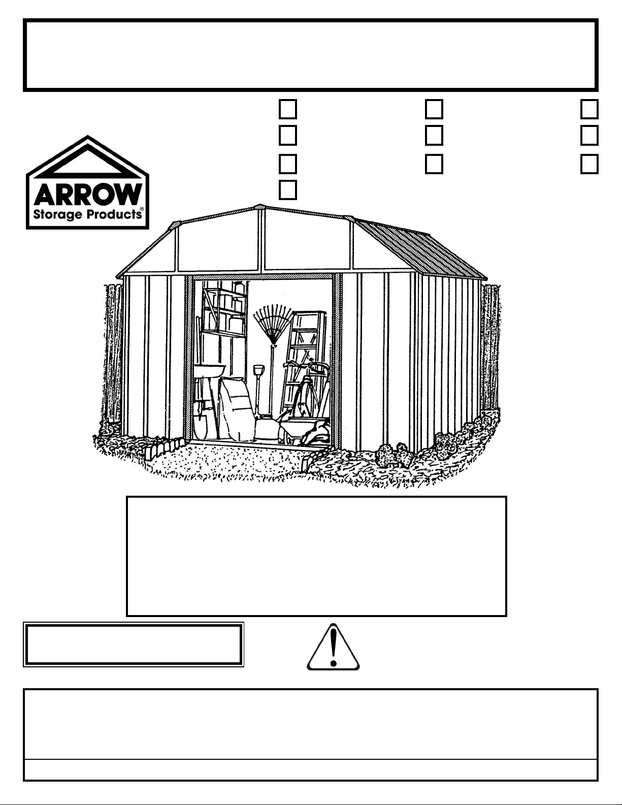
Owner's Manual & Assembly Instructions
SO01et
Model No. CO1014-C1 DK1014-B1 LX1014-C1
VS1014-C1 VY1014-A1 WV1014-C1
YT1014-C1 697.68604-A1 697.68630-A1
SG1014
Missing Parts, Questions on Assembly?
Call: 1-800-851-1085 or assist@arrow-
sheds.com
Do not return to dealer, they are not
715831015
Storage Area: 129 Sq. Ft. 852 Cu. Ft.
12,0 m
BUILDING DIMENSIONS * Size rounded off to the nearest foot
Exterior Dimensions Interior Dimensions Door
*Approx. Base (Roof Edge to Roof Edge) (Wall to Wall) Opening
Size Size Width Depth Height Width Depth Height Width Height
10' x 14' 121" x 160 1/4" 123 1/4" 162 3/4" 87 7/8" 118 1/4" 157 1/2" 86 5/8" 55 1/2" 60"
3,0 m x 4,0 m 307,3 cm x 407,0 cm 313,1 cm 413,4 cm 223,2 cm 300,4 cm 400,1 cm 220,0 cm 141,0 cm 152,4 cm
equipped to handle your requests.
CAUTION: SOME PARTS HAVE SHARP EDGES. CARE
MUST BE TAKEN WHEN HANDLING THE VARIOUS PIECES
2
24,1 m3
TO AVOID A MISHAP. FOR SAFETY SAKE, PLEASE READ
SAFETY INFORMATION PROVIDED IN THIS MANUAL
BEFORE BEGINNING CONSTRUCTION. WEAR GLOVES
WHEN HANDLING METAL PARTS.
Page 2

Page 3

A03
BEFORE YOU BEGIN....
Owner's Manual
Before beginning construction, check local building codes regarding footings, location
and other requirements. Study and understand this owner's manual.
Important information and helpful tips will make your construction easier and more
enjoyable.
Assembly Instructions: Instructions are supplied in this manual and contain all
appropriate information for your building model. Review all instructions before you begin,
and during assembly, follow the step sequence carefully for successful results.
Flooring and Anchoring: Your storage building must be anchored to prevent wind
damage. A base is necessary to construct a square and level building. Anchoring and
base materials are not included with your building. We recommend the combined use
of an Arrow Floor Frame Kit and an Arrow Anchoring Kit as an effective method of
securing your building to the ground (Available at your local dealer, Arrow's website
arrowsheds.com or call Arrow's Customer Service department 1-800-851-1085) or you
may construct a base and anchoring system of your choice. Your assembly instructions
provide information on a few methods commonly used to secure and level a storage
building.
Parts and Parts List: Check to be sure that you have all the necessary parts for
your building.
•All part numbers can be found on the parts. All of these numbers (before the -) must agree with the
numbers on the Parts List page.
•If you fi nd that a part is missing, include the model number of your building and contact:
Arrow Shed, LLC Customer Service Department
1101 North 4th Street Breese, Illinois 62230
•Separate contents of the carton by the part number while reviewing parts list. The fi rst few steps
show how to join related parts to make larger sub assemblies which will be used later.
•Familiarize yourself with the hardware and fasteners for easier use during construction. These are
packaged within the carton. Note that extra fasteners have been supplied for your convenience.
1-800-851-1085 or [email protected]
Page 4
A04
PLAN AHEAD....
Watch the Weather: Be sure the day you select to install your building is dry and calm.
Do not attempt to assemble your building on a windy day. Be careful on wet or muddy ground.
Teamwork: Whenever possible, two or more people should work together to assemble
your building. One person can position parts or panels while the other is able to handle the
fasteners and the tools.
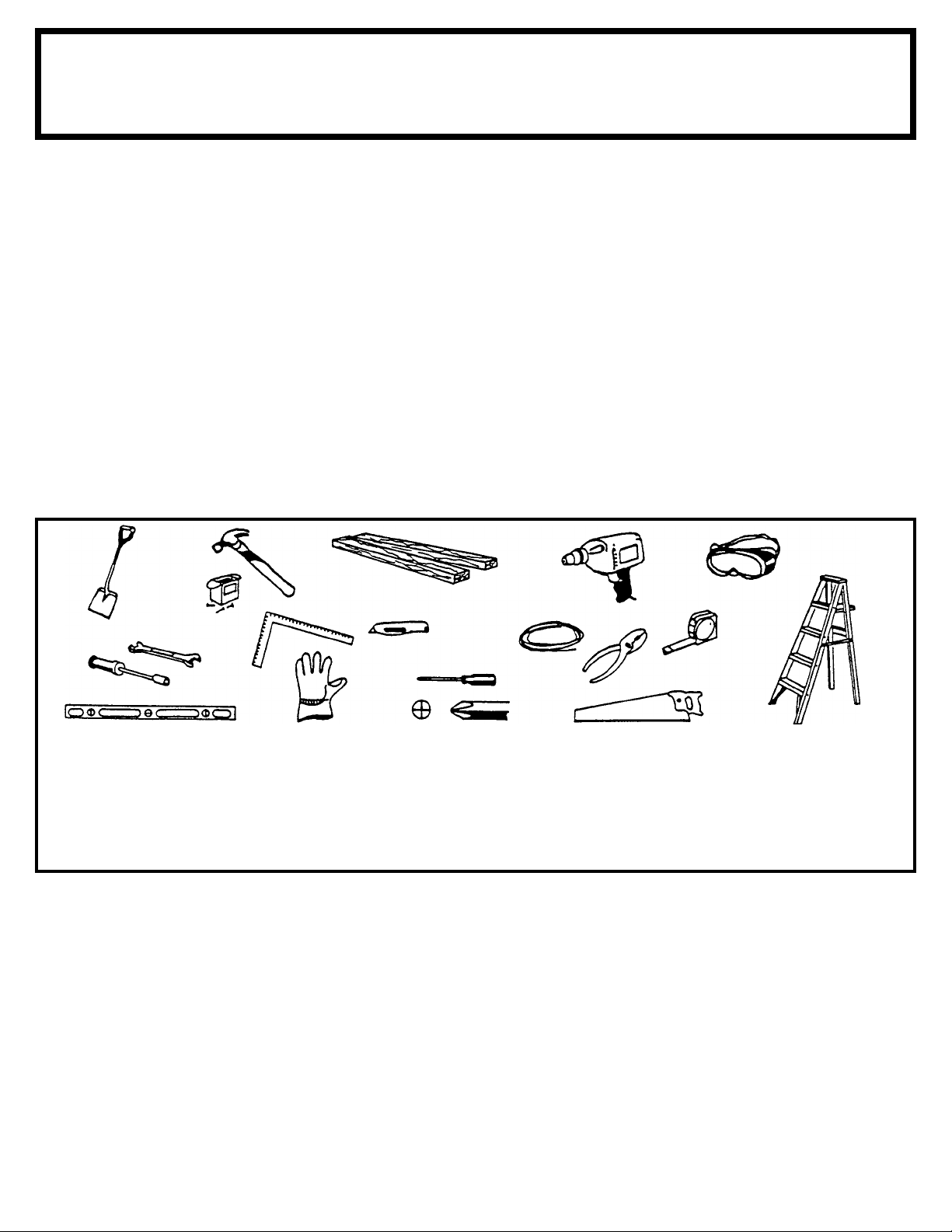
Tools and Materials: These are some basic tools and materials you will need for the
construction of your building. Decide which method of anchoring and the type of base you
wish to use in order to form a complete list of the materials you will need.
Required
• Eye Goggles
• No. 2 Phillips Screwdriver
(With Hardened Magnetic Tip)
Note: A power screwdriver or vari-
able speed drill with Phillips-tip
attachment can speed assembly by
as much as 40%.
• Work Gloves
• Step Ladder
• Utility Knife / Scissors
• Pliers
• Carpenter's Level
• Tape Measure
Required
Optional Time-Savers
• Wrench / Nut Driver
• Electric / Cordless Drill
• Square
• String (for squaring frame)
Base Preparation
• Hammer and Nails
• Spade or Shovel
• Hand Saw / Power Saw
• Lumber and/or Concrete
Selecting and Preparing Your Site: Before assembly, you will want to decide on a
location for your building. The best location is a level area with good drainage.
•Allow enough working space for ease of moving parts into position during assembly. Be sure there
will be enough space at entrance for doors to open fully and enough space around the building to
be able to fasten the panel screws from the outside.
•Before you begin the fi rst steps in assembling your parts, a base should be constructed and
an anchoring system should be ready to use.
Page 5
A05
Safety precautions are important to follow throughout the construction of your building.
SAFETY FIRST....
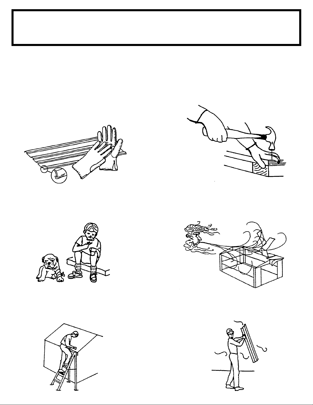
•Care must be taken when handling various
pieces of your building since some contain
sharp edges. Please wear work gloves, eye
protection and long sleeves when assembling
or performing any maintenance on your
building.
safety edge
sharp edge
sharp edge
safety edge
•Keep children and pets away from worksite
to avoid distractions and any accidents which
may occur.
•Practice caution with the tools being used in
the assembly of this building. Be familiar with
the operation of all power tools.
•Do not attempt to assemble the building if
parts are missing because any building left
partially assembled may be seriously damaged
by light winds. Call 1-800-851-1085 or assist@
arrowsheds.com
•Never concentrate your total weight on the
roof of the building. When using a step ladder
make sure that it is fully open and on even
ground before climbing on it.
•Do not attempt to assemble the building on a
windy day, because the large panels acting as a
"sail", can be whipped about by the wind making
construction diffi cult and unsafe.
Page 6
A06
CARE & MAINTENANCE....
Finish: For long lasting fi nish, periodically clean and wax the exterior surface. Touch-up
scratches as soon as you notice them on your unit. Immediately clean the area with a wire
brush; wash it and apply touch-up paint per manufacturer's recommendation.
Roof: Keep roof clear of leaves and snow with long handled, soft-bristled broom. Heavy
amounts of snow on roof can damage building making it unsafe to enter. In snow country,
Roof Strengthening Kits are available for most Arrow Buildings for added protection against
heavy snow accumulation. Contact Arrow as outlined on the Ordering Accessories page
to place an order.
Doors: Always keep the door tracks clear of dirt and other debris that prevent them from
sliding easily. Lubricate door track annually with furniture polish or silicone spray. Keep
doors closed and locked to prevent wind damage.
Fasteners: Use all washers supplied to protect against weather infi ltration and to protect
the metal from being scratched by screws. Regularly check your building for loose screws,
bolts, nuts, etc. and retighten them as necessary.
Moisture: A plastic sheet (vapor barrier) placed under the entire fl oor area with good
ventilation will reduce condensation.
Other Tips....
• Wash off inked part numbers on coated panels with soap and water.
• Silicone caulking may be used for watertight seals throughout the building.
Do not store swimming pool chemicals in your building. Combustibles and
corrosives must be stored in air tight approved containers.
Keep this Owner's Manual and Assembly Instructions for future reference.
Page 7
A07
BEFORE
AFTER
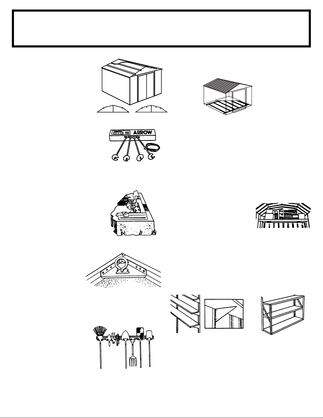
ACCESSORIES....
ROOF STRENGTHENING
(heavy snow load) KITS
Extra roof beams and gable braces
designed for added protection against
heavy snow accumulation. Increases
the strength of your roof.
ANCHOR KITS
Model No. AK4
Anchor Kit contains heavy-duty steel
augers, 60' (18 m) of steel cable and
4 cable clamps. No digging or concrete
pouring, just insert cable under roof,
over roof beams, into augers and twist
augers into the ground. For buildings
larger than 10'x9' (3,0 m x 2,6 m), use 2 kits.
Model No. AK100
New concrete anchor system permits
anchoring any size Arrow building
directly to a concrete slab. Each kit
contains heavy-duty, hot-dipped
galvanized steel corner gussets and
perimeter clips which fi t over the fl oor
frame and lag bolt into a concrete slab.
Full assembly instructions and a 1/4"
masonary drill bit are included.
FLOOR FRAME KITS
MODELS FB47410, FB5465, FB106-A
FB109-A and FB1014-A
A simple new fl oor frame system made of heavy-duty, hot-dipped
galvanized steel. Use as base for plywood, sand or stone.
ATTIC KIT / WORKBENCH KIT
Model No. AT101
Heavy-duty galvanized steel bars that
fi t all 10' (3,0 m) wide Arrow buildings.
They install quickly and easily to
help organize space and create
more useable space as an attic or
workbench. Will hold up to 250 lbs.
(113 kg) evenly distributed.
Some drilling required to fi t buildings without mid-wall bracing.
Model No. AK600
Earth Anchor Kit anchors any size
Arrow building to the ground.
Each kit contains heavy duty,
hot-dipped galvanized steel
corner gussets and 4 earth anchors.
TOOL HANGING RACK
Model No. TH100
The perfect tool organizer. Twin
25 1/2" (64,8 cm) steel channels
plus fi ve heavy-duty snap-in
hangers and a small tool holder for
screwdrivers, pliers, etc. Holders
slide along channel for fully
adjustable spacing. Great for
garage, basement, or the back
of any door. Fits all Arrow
storage buildings.
SHELF UNITS
Heavy-duty, galvanized steel shelf units help organize storage
space. They easily mount on the wall or sit on the fl oor. Fits all
Arrow buildings.*
Model No. SS404
• Makes 8" to 12" (20,3-30,5 cm)
wide shelves in any length.
• Brackets, braces,
hardware included.
Lumber is not included.
* Some drilling required to fi t buildings without mid-wall bracing.
Model No. SS900-B
• Grey color
• 3 shelves
• Holds up to 85 lbs. (38 kg)
(even weight distribution)
Page 8
A08 02/13
We recommend that you purchase accessory items from your local storage building dealer whenever possible;
however, because the full line of accessories is not always available from all dealers, Arrow is offering them
to you on a direct basis.
There are two ways to order Arrow Storage Building Accessories:
ORDERING ACCESSORIES....
Option 1
Accessories can be purchased
through
arrowsheds.com
SPECIAL NOTE:
If your accessory is shipped via truck line a day time phone number is required to arrange delivery. If no
one is available to sign for the delivery, you may be subject to a re-delivery charge assessed by the carrier.
Order accessories by telephone
using your MasterCard or Visa credit card.
Call toll free 1-800-851-1085
Allow 2 weeks for delivery.
Option 2
(Customer Service).
Page 9
F09
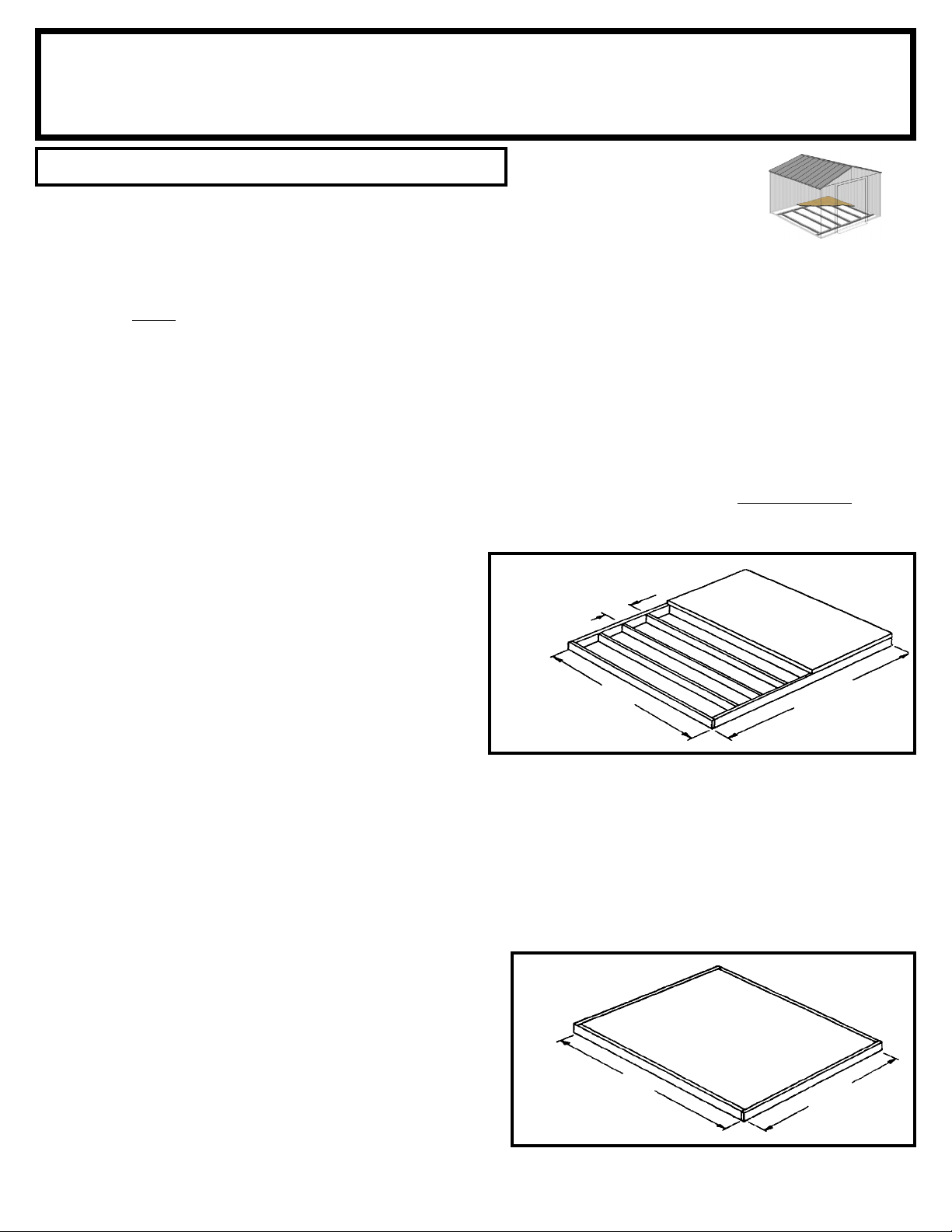
Base
The Base For Your Building
No matter which of the options below you choose for a base, an ARROW ANCHORING KIT is
recommended as an effective method of properly securing your building after assembly is complete.
OPTION 1: Directly on ground (earth)
Assemble your building directly on level ground (grass, dirt, rock, sand, etc.). If you choose this option Arrow has a simple kit available to
provide a fl oor inside the shed to keep stored items off the ground. This kit can be used to support a plywood fl oor (wood not included)
or be fi lled with sand/rock to provide a solid surface. (Order No. FB1014-A or 68387-A)
Allow 1 - 2 hours for construction.
OPTION 2: Wood Platform
If you decide to build your own base, be sure to select the appropriate materials.
These are the recommended materials for your base:
2 x 4's (38 mm x 89 mm) Pressure Treated Lumber
5/8" (15,5 mm) 4 x 8 (1220 mm x 2440 mm) Plywood-exterior grade NOTE: Pressure Treated Lumber must not be used where it
will make contact with your storage building. The properties of Pressure Treated Lumber will cause accelerated corrosion.
If Pressure Treated Lumber comes in contact with your storage building your warranty will be voided.
10 & 4 penny Galvanized Nails Concrete Blocks (optional)
The platform should be level and fl at (free of bumps, ridges etc.)
to provide good support for the building. The necessary materials
may be obtained from your local lumber yard.
To construct the base follow instructions and diagram.
Construct frame (using 10 penny galvanized nails)
Measure 16"/24" (40,6 cm/61,0 cm) sections to construct
inside frame (see diagram)
Secure plywood to frame (using 4 penny galvanized nails)
Allow 6 - 7 hours for construction.
FRONT
(DOOR)
Note: Platform/Slab will extend 9/16" (1,4 cm) beyond fl oor
frame on all four sides. Seal this 9/16" (1,4 cm) of wood with a
roofi ng cement (not included), or bevel this 9/16" (1,4 cm) of
concrete when pouring, for good water drainage.
16"/24"
40,6 cm/61,0 cm
121"
307,3 cm
OPTION 3: Concrete Slab
The slab should be at least 4" (10,2 cm) thick. It must be level and fl at to provide good support for the frame.
The following are the recommended materials for your base.
1 x 4's (19 mm x 89 mm) (will be removed once the concrete cures)
Concrete Sheet of 6 mil plastic
We recommend for a proper strength concrete to use a mix of:
1 part cement 3 parts pea sized gravel 2 1/2 parts clean sand
Prepare the Site/Construct a Base
1. Dig a square, 6" (15,2 cm) deep into the ground (remove grass).
2. Fill up to 4" (10,2 cm) in the square with gravel and tamp fi rm.
3. Cover gravel with a sheet of 6 mil plastic.
4. Construct a wood frame using four planks of 1x4 (19 mm x 89 mm)
lumber.
5. Pour in concrete to fi ll in the hole and the frame giving a
total of 4" (10,2 cm) thick concrete. Be sure surface is level.
FRONT
(DOOR)
121"
307,3 cm
160 1/4"
407,0 cm
160 1/4"
407,0 cm
Allow 3 - 5 hours for construction and a week for concrete curing time.
9
Note: Finished Slab dimensions, with lumber removed.
Page 10
A10
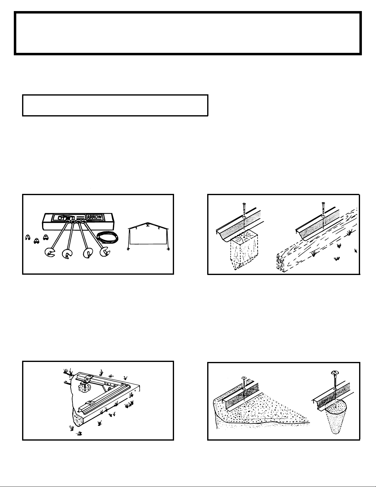
Anchoring
Anchoring Down The Building
It is important that the entire fl oor frame be anchored after the building is erected.
Below are recommended ways of anchoring.
Arrow Anchoring Kit: (Model No. AK4 or 60298)
Recommended for use with any suggested base.
Contains: 4 Anchors with Cable, Clamps and
installation instruction.
Anchoring into Wood/Post:
Use 1/4" (6 mm) Wood Screws. There are 1/4" (6 mm)
dia. holes provided in the frames for proper anchoring.
1. 2.
OVER THE BEAMS
AND INTO THE GROUND
Arrow Anchoring Kit: (Model No. AK100 or 68383)
Recommended for use with the concrete base.
Contains: Corner gussets, perimeter clips, hardware,
1/4" masonary drill bit and installation instruction.
Anchoring into Concrete:
1. For poured concrete slab or footing or patio blocks:
Use 1/4" x 2" (6 mm x 51 mm) Lag Screws.
2. For Anchor Post of Concrete poured after building is
erected: Use 1/4" x 6" (6 mm x 152 mm) Lag Screws.
1.
2.
10
Page 11
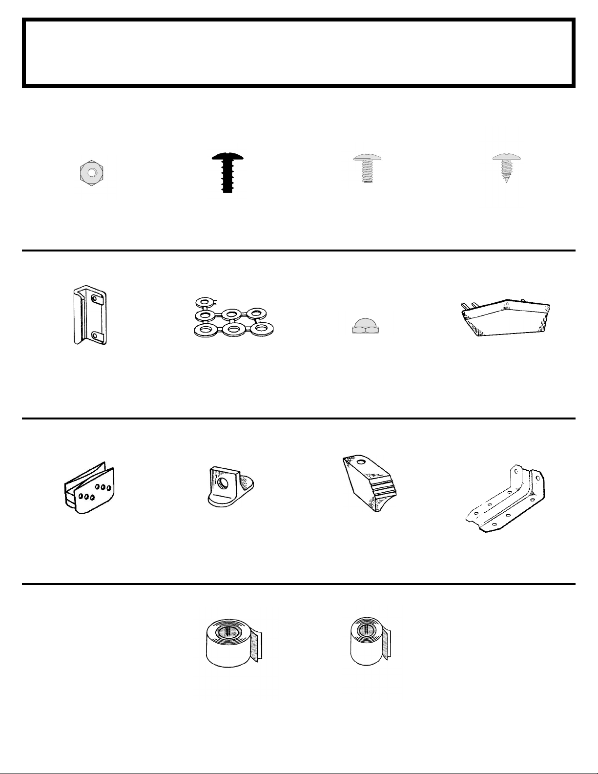
SO11 ctr
65103
#8-32 Hex Nut (240)
Hardware
Remove from bag of screws
and save for the last step
65900A
#10Bx1/2" (13 mm)
Black Screw (8)
(Packed with Screws)
65923
#8-32x3/8" (10 mm)
Bolt (240)
65004
#8Ax5/16" (8 mm)
Screw (446)
66045
Handle (2)
66769
Door Slide (4)
66646
Washer (521)
(14 sheets of 40)
66382
Lower Door Guide (4)
65109
#8-32 Acorn Nut (4)
(Packed with Screws)
66183
Roof Trim Cap
(2 right & 2 left)
67468
Peak Cap (6)
(Arrow Logo)
6228
Track Support (2)
67545
Weather Stripping (1)
Weather Stripping (1)
11
67293
Page 12
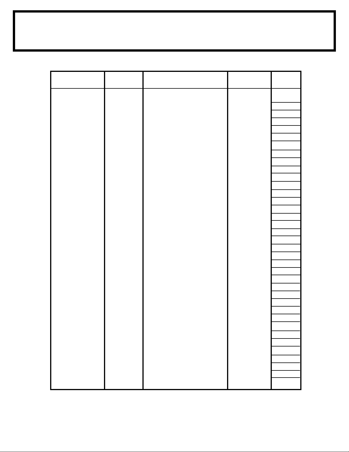
SO12et ctr
Parts List
Assembly Part Part Quantity Check
Key No. Number Description In Carton List
1 3719 Door Handle Brace 2
2 9373 Front Wall Panel 2
3 6020 Corner Panel 4
4 6108 Large Right Gable 2
5 6109 Large Left Gable 2
6 6114 Small Right Gable 2
7 6115 Small Left Gable 2
8 6188 Right Roof Panel 2
9 6189 Left Roof Panel 2
10 10497 Horizontal Door Brace 4
11 6278 Vertical Door Brace 2
12 6515 Wall Panel 12
13 6538 Roof Panel 8
14 10475 Right and Left Doors 2
15 9369 Door Jamb 2
16 67521 Edge Trim (Clear) 2
17 6015 Side Roof Trim 2
18 6403 Door Track Splice 1
19 6797 Ridge Cap 6
20 6869 Ridge Cap 3
21 6892 Right Side Roof Trim 2
22 6893 Left Side Roof Trim 2
23 9366 Door Track 2
24 5986 Rear Wall Angle 2
25 10389 Rear Wall Channel 2
26 10388 Side Wall Channel 4
27 9365 Front Wall Channel 2
28 6085 Roof Beam Bracket 4
29 6227 Roof Beam Brace 2
30 10386 Roof Beam 8
31 6636 Gable Brace 2
32 10391 Side Wall Angle 4
33 8936 Rear Floor Frame 2
34 10387 Side Floor Frame 4
35 9367 Front Floor Frame 2
36 8934 Ramp 1
37 69835 Edge Trim (Green) 4
12
Page 13
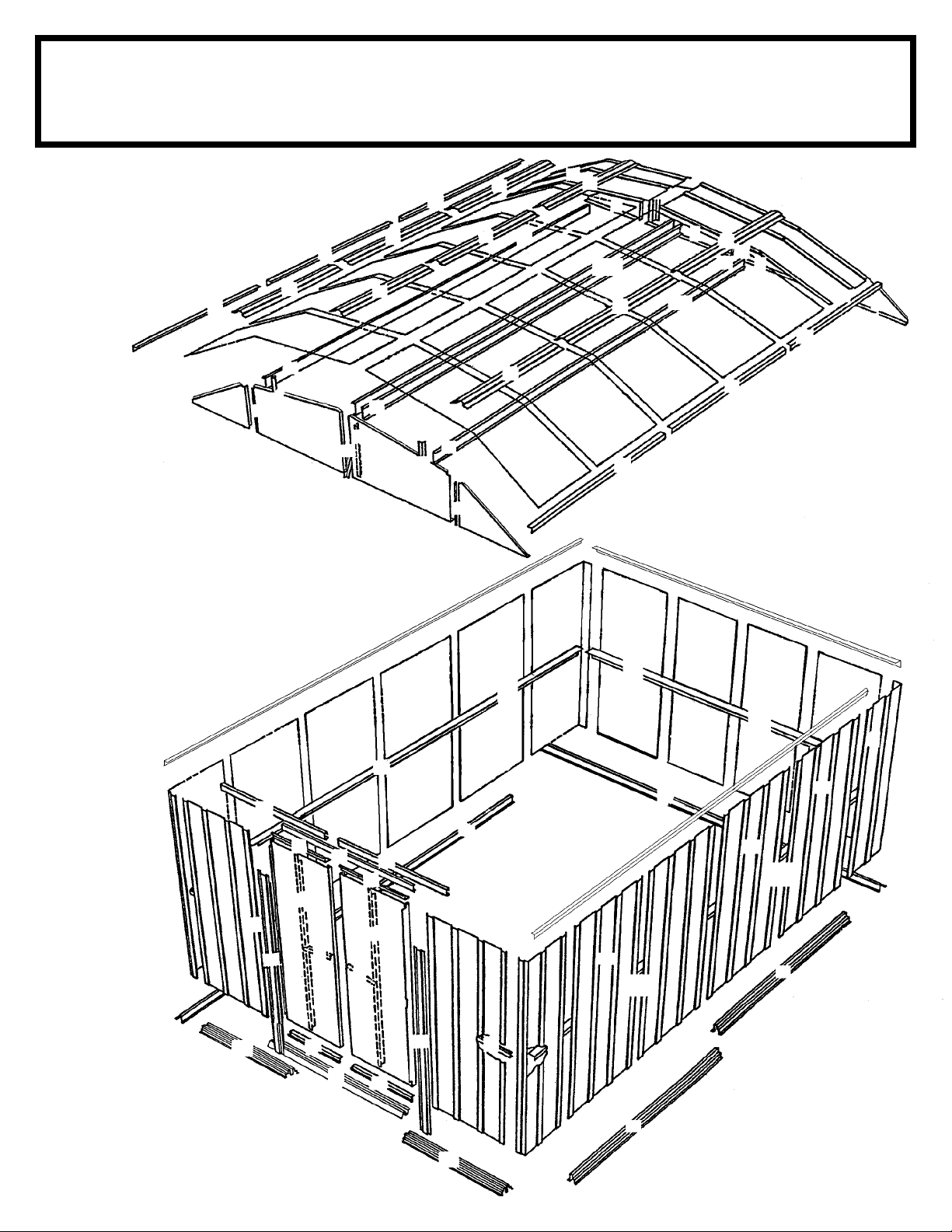
SO13et ctr
Assembly by Key No.
9
22
19
13
19
28
6
34
21
37
3
13
24
33
30
12
4
12
13
19
31
17
29
12
25
32
5
13
12
26
34
8
21
24
12
28
12
37
7
3
33
13
30
16
32
34
20
30
30
30
20
19
13
9
37
6
3
12
26
2
3
22
12
25
32
12
26
20
17
19
13
8
30
37
28
7
16
5
29
32
12
12
23
27
15
14
10
18
11
1
2
30
31
13
19
30
37
28
4
12
26
23
10
11
1
14
35
10
36
10
15
27
34
35
13
Page 14
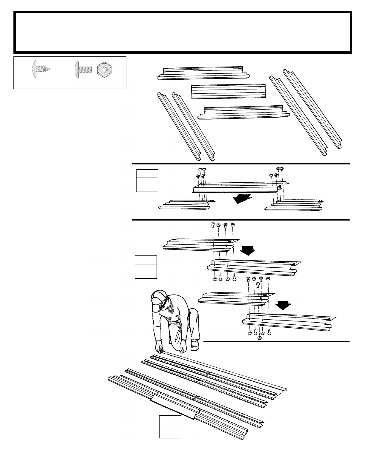
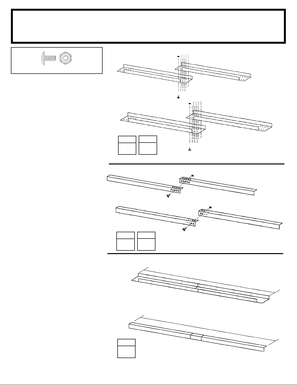
Step 1
SO14ctr
Parts Needed For
Floor Frame Assemblies
8934 Ramp (1)
9367 Front Floor Frame (2)
8936 Rear Floor Frame (2)
10387 Side Floor Frame (4)
(8) (13)
The front fl oor frame is made up of
three pieces. The side fl oor frames
and the rear fl oor frame are made
up of two pieces. The holes in these
pieces will align when the pieces are
positioned with correct amount of
overlap. The illustrations below show
the proper overall length for the sides,
rear and front. Proceed as follows:
1 Place the front fl oor frames as
shown. Center the ramp, with drain
holes facing outside, on top of the two
front fl oor frames. Join the frames by
inserting eight screws.
2 Overlap the side fl oor frames
and the rear fl oor frames as shown.
The holes in these pieces will align
when the pieces are positioned with
correct amount of overlap. See the
illustrations below for the proper over-
all length of the side and rear fl oor
frames. Join the frames by inserting
four/fi ve bolts into each frame set as
shown.
STEP
1
STEP
2
10387
9367
10387
9367
8934
DRAIN HOLES FACE
OUTSIDE
8936 8936
9367
8936
Front Floor
8934
Side Floor Frame 158 5/8" 402,9 cm
10387
Rear Floor Frame 119 3/8"
Frame Assembly
119 3/8" 303,2 cm
9367
303,2 cm
3 Double check the length of each
and set these pieces aside for later
use.
STEP
3
158 5/8" 402,9 cm
Sides
158 5/8" 402,9 cm
119 3/8" 303,2 cm
Front & Rear
119 3/8" 303,2 cm
14
Page 15
Step 2
SO15 ctr
(27)
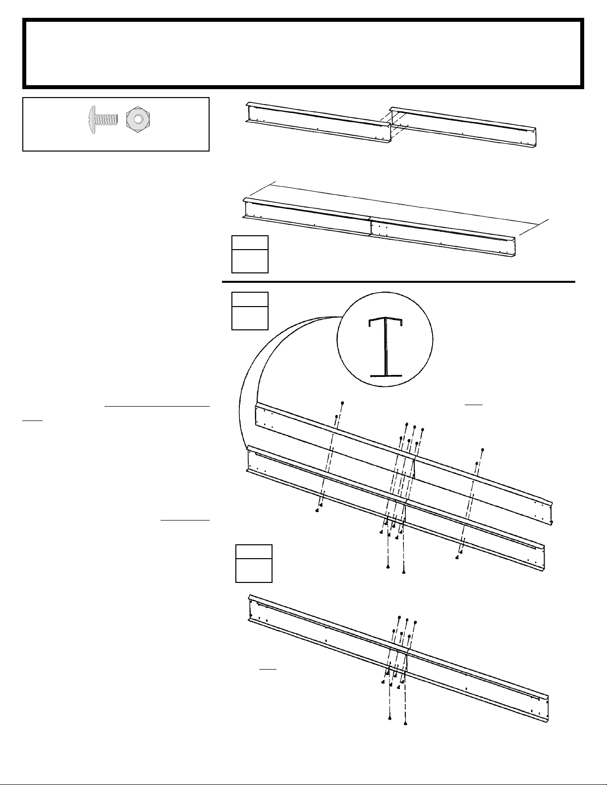
The main frame pieces reinforce
the walls. These pieces will later be
installed in the center and at the top
edge of the side walls and the rear
wall. Proceed as follows:
Parts Needed For
Frame Assemblies
10389
10388
5986 Rear Wall Angle (2)
10389 Rear Wall Channel (2)
10388 Side Wall Channel (4)
10391 Side Wall Angle (4)
Rear Wall Channel
118 1/8" 300,0 cm
10389
Side Wall Channels
157 3/8" 399,7 cm
1 Overlap the rear wall channel
pieces as shown in the fi gure and
fasten the two pieces together with
eight bolts as shown.
2 Make two side wall channels by
overlapping the side wall channel
pieces as shown. Fasten each set
together with eight bolts as shown.
3 Overlap the rear wall angle
pieces as shown in the fi gure and
fasten them together with one bolt
in the center hole.
4 Make two side wall angles by
overlapping the side wall angle pieces
as shown. Fasten each set together
with one bolt thru the second large
hole from the end of each part.
STEP
1
STEP
3
STEP
2
5986
STEP
4
10388
Rear Wall Angle
118 1/8" 300,0 cm
5986
10391
10391
Rear Wall Channel 118 1/8" 300,0 cm
Side Wall Channels 157 3/8" 399,7 cm (2 Assemblies)
Side Wall Angles
157 3/8" 399,7 cm
5 Double check the length of each
and set these pieces aside for later
use.
Rear Wall Angle 118 1/8" 300,0 cm
Side Wall Angles 157 3/8" 399,7 cm (2 Assemblies)
STEP
5
15
Page 16
Step 3
SO16ctr
(30)
Parts Needed For
Roof Beam Assemblies
10386
10386 Roof Beam (8)
10386
The roof beams join the two gables
and support the roof panels. The
main roof beam is made up of four
pieces overlapped back to back at
the center. The left and right roof
beam assemblies are made up of
two pieces.
Hint: These pieces are force-fi tted,
so you may have to press hard to join
them together.
1 Place the end of one roof beam
inside a second roof beam so that the
six holes in each piece align. Make
four sets of roof beams by repeating
this procedure. Do not insert bolts
yet.
2 Take two of the pressed-together
roof beams and join them as shown
to form the main roof beam assembly. Hold the assembly together and
fasten with 14 bolts. Build only one
Doubled Beam Assembly.
STEP
1
STEP
2
10386
10386
Roof Beam 159 3/8" 404,8 cm
ASSEMBLED
END
VIEW
Build one Doubled Main Roof
Beam Assembly for Peak in Roof
10386
3 Fasten the other two pressed-
together roof beams with eight bolts
to make the left and right roof beam
assemblies.
4 Double check the length of each
and set these pieces aside for later
use.
STEP
3
Build two Single Beam
Assemblies
16
10386
159 3/8" 404,8 cm
159 3/8" 404,8 cm
Page 17
Step 4
A17 ctr
(4)
Parts Needed For
Door Track Assembly
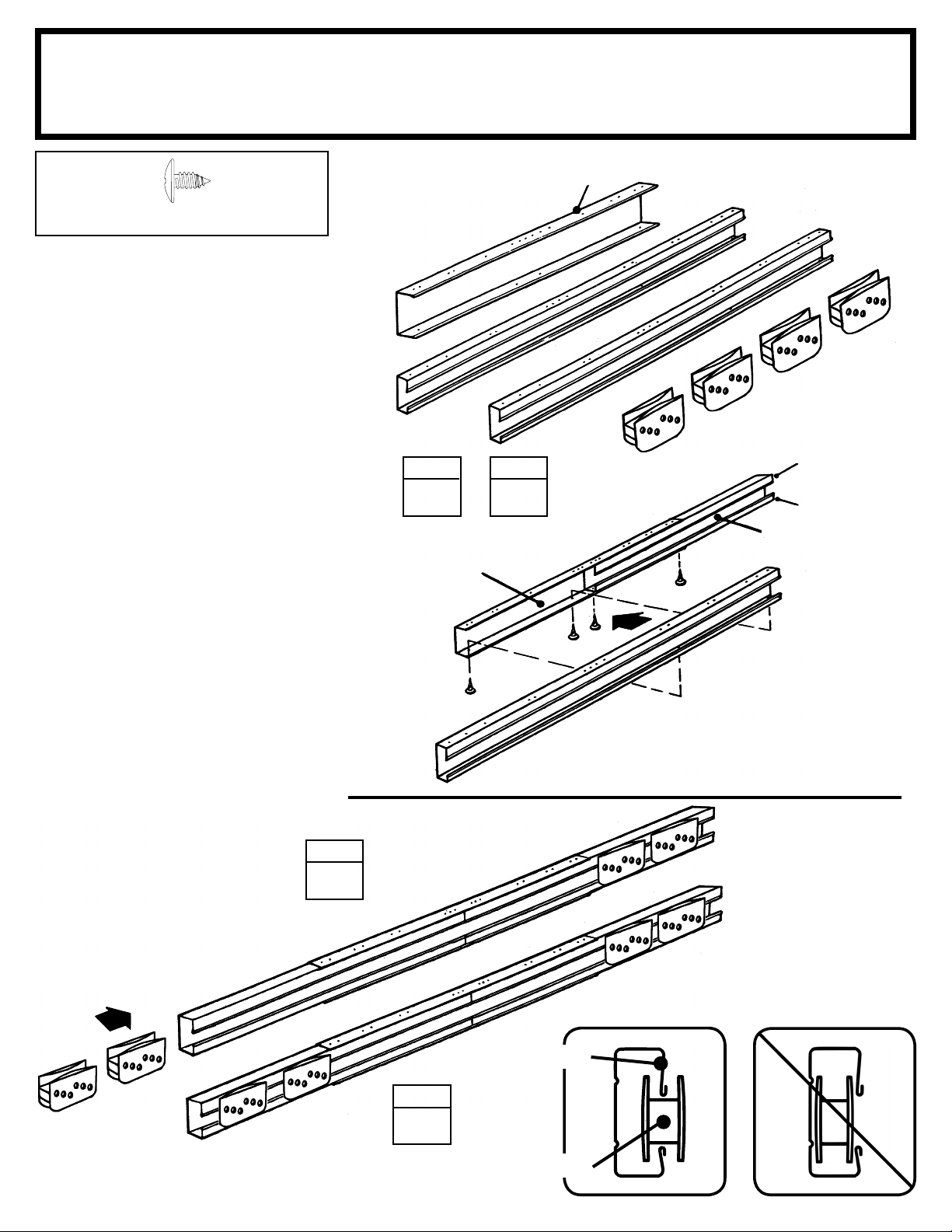
NOTE:
Door Track Splice (painted part)
6403 Door Track Splice (1)
9366 Door Track (2)
The door track assembly supports the
sliding doors and reinforces the front
wall. It is made up of three pieces.
1 Using the door track splice,
(painted), join the door track
(galvanized) pieces end-to-end as
shown.
2 Insert four screws from the
underside only.
Hint: The holes in the top side of the
door track assembly are for fastening
the gable to the top of the front wall
in a later step.
6403
STEP
1
9366
6403
STEP
2
66769
9366
Long Leg
on Top
Short Leg
on Bottom
9366
3 Position door slides onto the
legs, from the end of door track
assembly, as shown in the end view.
4 Set this piece aside for later use.
STEP
4
118 1/8"
300,0 cm
66769
118 1/8"
300,0 cm
118 1/8"
300,0 cm
STEP
3
Long Leg on top.
Door Slide
17
9366
CORRECT
END VIEW
INCORRECT
Page 18
Step 5
SO18 ctr
(8) (2)
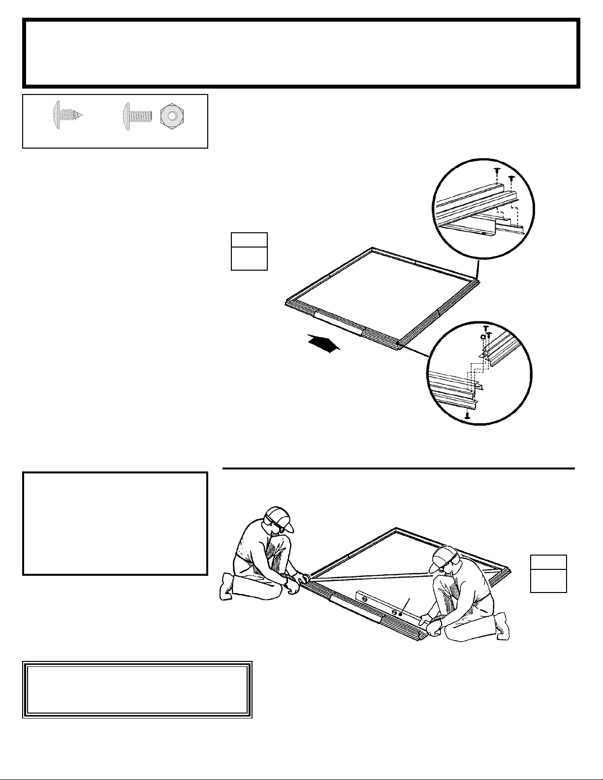
1 Assemble the four corners of
the fl oor frame using two screws at
each corner as shown. At the front
corners fasten bolts through from
the bottom with nuts on top.
Parts Needed For
Floor Frame
STEP
1
Front Floor Assembly (1)
Side Floor Assembly (2)
Rear Floor Assembly (1)
RIGHT
REAR
10387
8936
2 Measure the fl oor frame diagonally.
When the diagonal measurements
are equal, the fl oor frame is square.
NOTE
If using a wood platform or
concrete slab do not fasten the
fl oor frames to your base at this
time. You will anchor the
building after it is erected.
FRONT
RIGHT
FRONT
10387
9367
When Diagonal Measurements
are Equal the Floor Frame
is Square.
STEP
2
Level
The fl oor frame must be square
and level or holes will not align.
18
Page 19
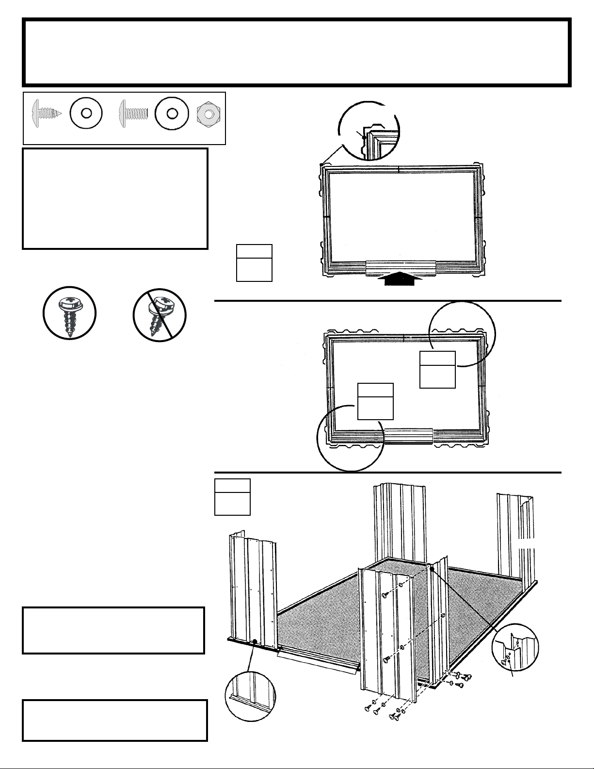
Step 6
SO19 ctr
Parts Needed For
Corners
6515 Wall Panel (2)
9373 Front Wall Panel (2)
6020 Corner Panel (4)
Narrow
Side
(34)
NOTE
The remainder of the building assembly
requires many hours and more than one
person. Do not continue beyond this
point if you do not have enough time to
complete the assembly today. A partially
assembled building can be severely
damaged by light winds.
(4)
Each screw and bolt in the wall
requires a washer.
CORRECT INCORRECT
1 Position a corner panel at the
corner of the fl oor frame as shown.
The widest part of each corner panel
must be placed along the side of the
building for all four corners. Fasten
the corner panel to the fl oor frame
with three screws.
STEP
1
Wide Side
SIDE
6020
6020
6515
9373
TOP VIEW
FRONT
STEP
2
REAR
6020
SIDE
6020
6515
STEP
3
9373
Support the corner panel with a step
ladder until a wall panel is attached.
2 Attach the front wall panels to
the front corner panels, as shown.
A small gap will exist between front
wall panel and ramp.
3 Attach the wall panels to the rear
corner panels, as shown.
NOTE
Be careful to install the correct
panel in each position as shown
4 Double-check the part numbers of
the wall panels, before proceeding.
The fl oor frame must be square
and level or holes will not align.
STEP
4
6020
9373
9373
Panels rest on
frame as shown
19
6020
6515
6515
6020
6020
Washer
Page 20
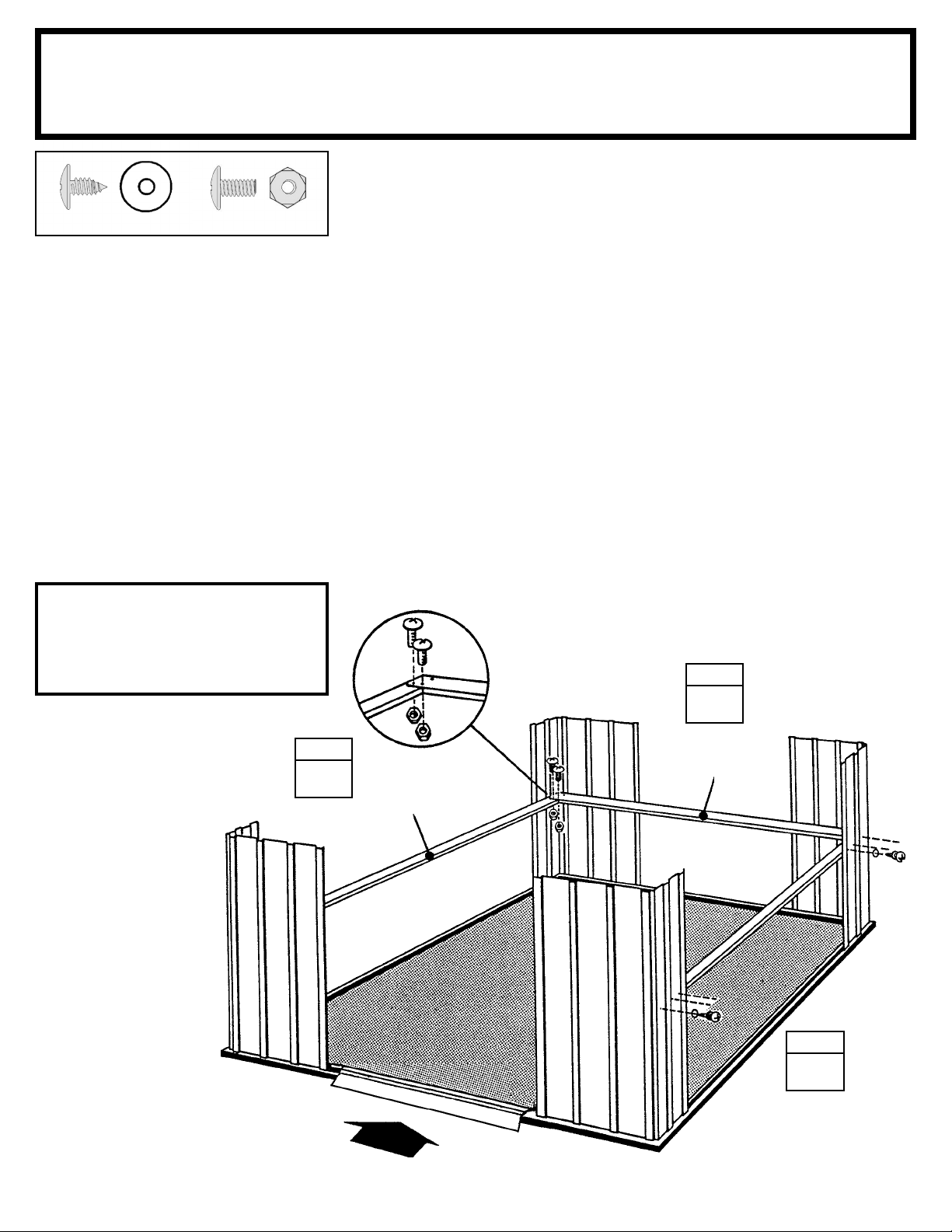
Step 7
SO20 ctr
Parts Needed For
Mid Frames
Rear Wall Channel Assembly (1)
Side Wall Channel Assembly (2)
(20)
The mid frame pieces give rigidity to
the side and rear walls.
(4)
1 Fasten the rear wall channel
across the middle of the rear wall
using screws.
2 Fasten the side wall channels
across the middle of the side panels
using screws. Fasten overlaps in
rear corners with bolts and nuts, at
two locations. See the fi gure.
NOTE
The wall channels behind the
front wall panels will be installed
in a later step.
STEP
STEP
2
1
10389
10388
STEP
2
FRONT
20
Page 21
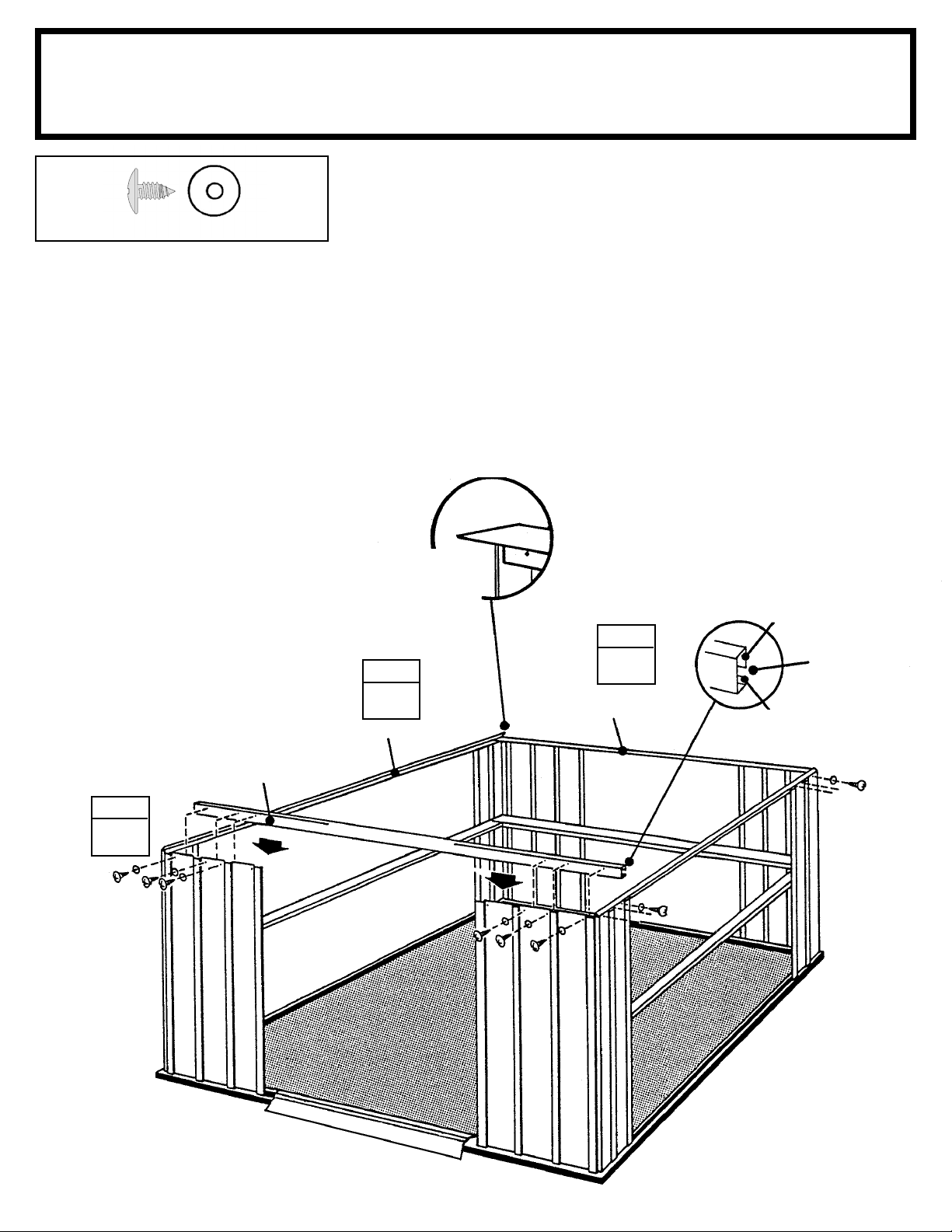
Step 8
SO21 ctr
(26)
The top frame pieces give rigidity to
the walls and provide a surface for
attaching the gables which support
the roof.
1 Fasten the rear wall angle across
the inside top of the rear wall using
screws.
2 Fasten the side wall angles across
the inside top of the side panels using screws. Side wall angles must
overlap rear wall angle in corners.
3 Fasten the door track assembly
(holes on top) across the top of the
front wall panels using screws. See
the fi gure.
Parts Needed For
Top Frames
Wall Angles
Must Face
Inside
Building
STEP
2
10391
STEP
5986
Door Track Assembly (1)
Rear Wall Angle Assembly (1)
Side Wall Angle Assembly (2)
Long Leg
on Top
1
Opening
facing in
Short Leg
on Bottom
STEP
3
9366
DOOR TRACK ASSEMBLY
FRONT
21
Page 22
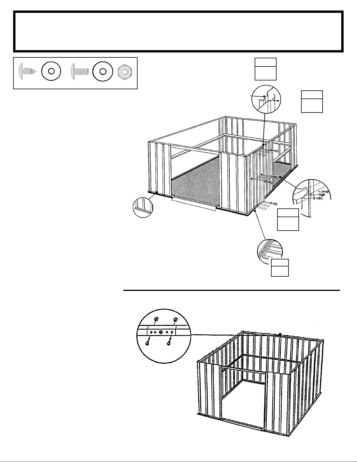
Step 9
SO22 ctr
(144) (15)
Parts Needed For
Wall Panels
6515 Wall Panel (10)
STEP
4
Each wall panel has a crimped rib
on one side. The crimped rib should
go under the rib of the panel that
follows it.
1 Locate all of the wall panels and
set each one alongside the building.
2 Fasten the wall panels at the top
and bottom with screws.
3 Fasten the center of each panel to
the wall channel with screws.
4 Fasten overlapping ribs as before.
Panels rest on
frame as shown
Crimped Rib
Underneath
6515
6515
STEP
STEP
1
STEP
Detail Showing
Center of
Panel Screwed
to Wall Channel
3
2
Bolt and nut
does not go
thru wall
channel at
overlap
Use bolts and nuts
thru wall angle
overlap at the top
of panel at rear.
22
Page 23
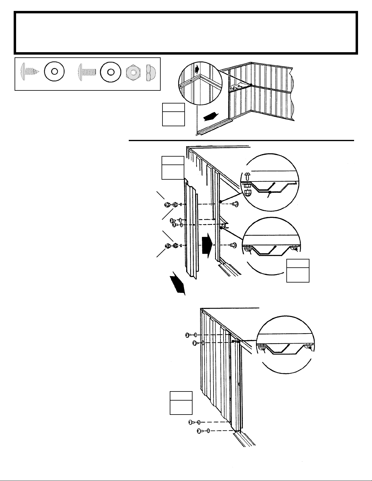
Step 10
SO23 ctr
Parts Needed For
Front Channel/Door Jamb
9365
9369 Door Jamb (2)
9365 Front Wall Channel (2)
(18)
(4)
The door jambs reinforce the door
opening and provide an attractive
trim. Follow these steps for both
door jambs.
1 Fasten the front wall channels
in their positions between the end of
the side wall channel and the corner
panel using screws. Do not put a
screw in the hole at the end behind
the door opening at this time.
2 Fasten a door jamb to the front
panel with two bolts, nuts and acorn
nuts, as shown.
3 Fasten the center of the door
jamb to the front wall panel and the
front wall channel with two screws.
Acorn Nut
Hex Nut
Acorn Nut
STEP
1
STEP
2
9369
FRONT
FRONT
INSIDE OF
BUILDING
(2) bolts
Bolt
Screw
TOP VIEW
Door Track
TOP VIEW
Front Wall Channel
9369
Front Wall Channel
Cross-Section
Top View
Screw
STEP
3
4 Fasten the top of the door jamb
to the door track with two screws. Do
the same for the bottom into frame.
Repeat steps 2 through 4 for the
opposite door jamb.
STEP
4
23
Screw
TOP VIEW
Door Track
Screw
Page 24
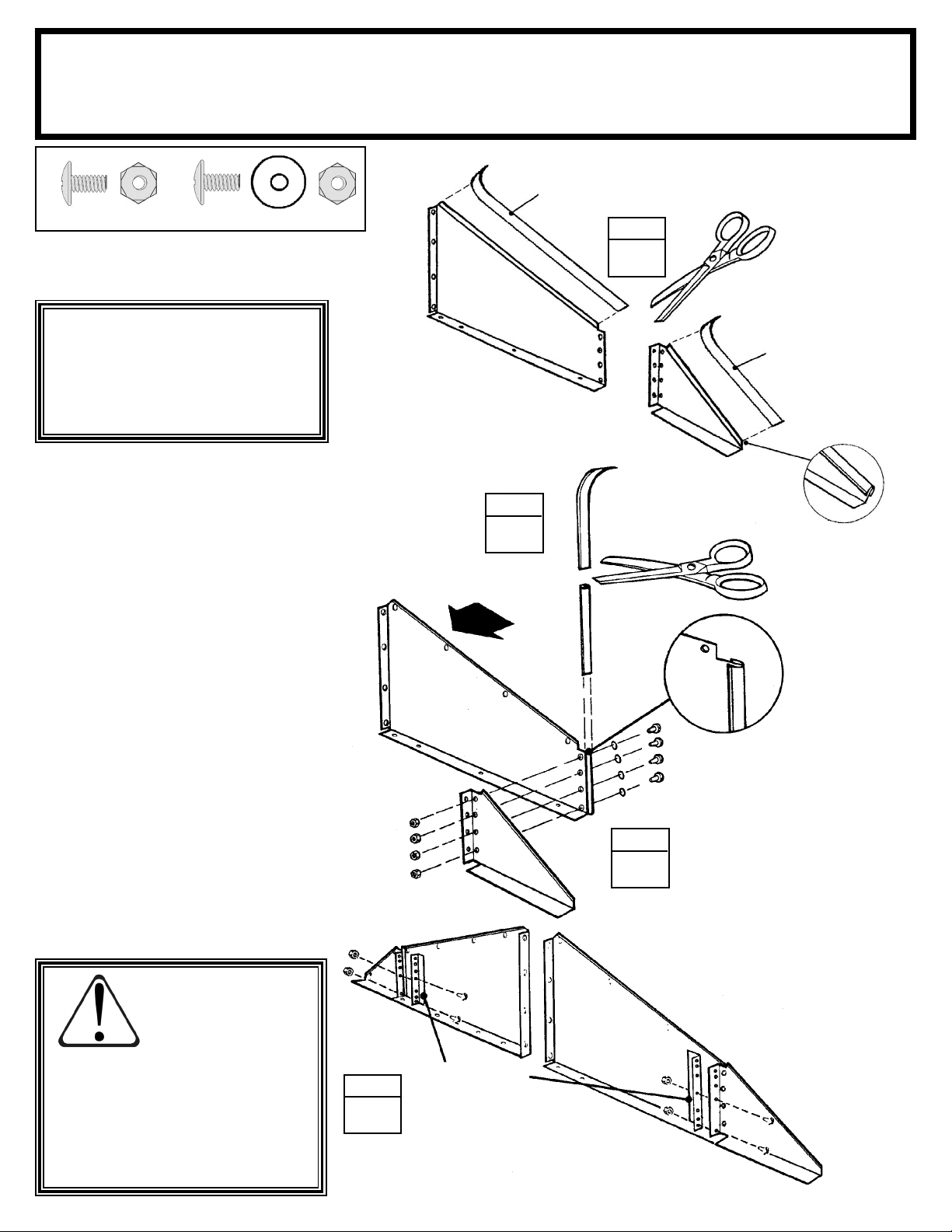
Step 11
SO24et ctr
(8)
(16)
Parts Needed For
Gable Assemblies
Green Edge Trim
(Plastic Piece)
6108 Large Right Gable (2)
6109 Large Left Gable (2)
6114 Small Right Gable (2)
6115 Small Left Gable (2)
6085 Roof Beam Bracket (4)
69835
STEP
The gables go on top of the front and
rear walls to support the roof beams.
NOTE
The gables are packed nested
together and might be mistaken
as one piece. Carefully separate
them before continuing.
1 Apply green edge trim to the top
edge of the large left gables, small
left gables, large right gables and
small right gables, cut to length.
2 Apply clear edge trim to the edge
of the large left gables and the large
right gables, cut to length.
3 Join the large gables to the small
gables on the left and right sides using four bolts, washers and nuts on
each side. This part of the gable is
called the outer gable leg.
6109
6109
STEP
2
FRONT
1
69835
Green Edge Trim
(Plastic Piece)
6115
67521
Clear Edge Trim
(Plastic Piece)
Washer
4 Attach the four roof beam
brackets to the outer gable legs
using two bolts in the two bottom
holes of the four holes that align.
To avoid mishap on the sharp
edge the edge trim must remain
in place on the top edge of the
gable until right and left roof
panels are in place.
CAUTION:
6114
STEP
STEP
6115
6108
6085
Roof Beam Brackets
3
4
24
Page 25
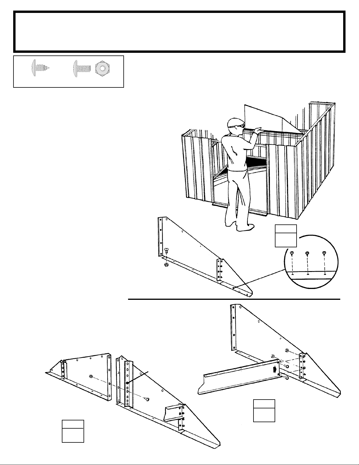
Step 12
SO25 ctr
(28) (12)
1 Lift and fasten a right and left gable,
under angle at corner, to the
door track and rear wall angle with
screws.
Hint: On the front gable, leave out 2
screws closest to center gable leg.
On the rear gable, use a bolt and nut
at the overlapping rear wall angle.
2 Fasten the single roof beam to the
outer gable leg as shown using bolts.
Parts Needed For
Gables/Roof Beams
Left Gable Assemblies (2)
Right Gable Assemblies (2)
Single Roof Beam Assemblies (2)
6636 Gable Brace (2)
Hint: The holes along the length of
the beam must be on the top surface.
Repeat Step 1 for the opposite side
of building.
3 Join the left and right gables
together with a gable brace using
a bolt in the second hole from the
bottom only. Do this step for both
front and rear gables.
Repeat Step 2 for the opposite side
of building.
Nut and bolt
at rear of building.
6636 Gable Brace
STEP
1
Gable
STEP
3
10386 Roof Beam (Single)
STEP
2
25
Page 26
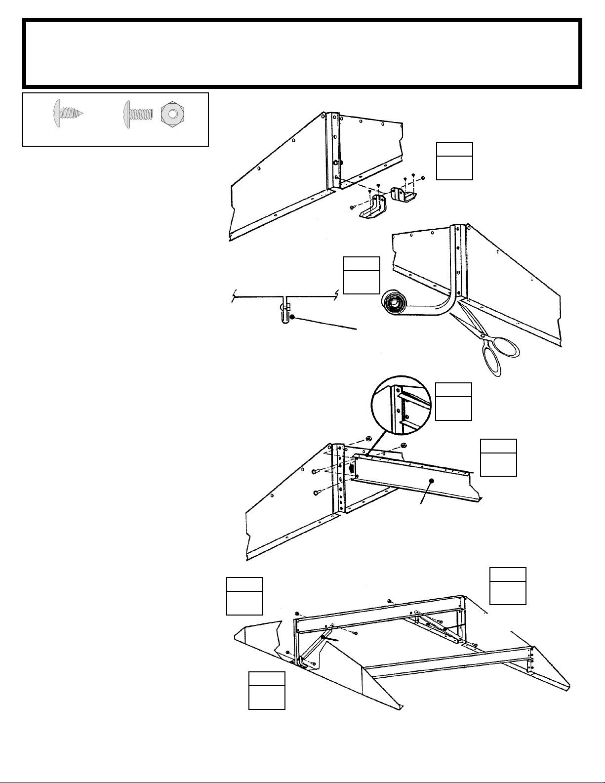
Step 13
SO26 ctr
(4) (9)
Parts Needed For
Roof Beam/Braces
Main Roof Beam Assembly (1)
6227 Roof Beam Brace (2)
STEP
1 Fasten the track supports to the
front gable assembly only, as shown.
2 Wrap the weather stripping tape
around the two joined edges of the
large left and right gables. See diagram. Cut the weather stripping to
length and repeat on next gable set.
3 Spread the two halves of the double
roof beam and fasten to the gable
brace of the front gable.
4 Fasten the other end of the double
roof beam to the gable brace of the
rear gable.
5 Fasten a roof beam brace to the
double roof beam behind the front
gable by placing the tab on the end
of the brace between the roof beams.
Align the tab with the second hole and
fasten the brace with a bolt and nut.
STEP
2
Spread Two Halves
Of Roof Beams
1
Track Supports 6228
Weather Stripping
STEP
3
STEP
4
10386 Roof Beam (Double)
6 Fasten the lower end of the roof
beam brace to the track support
with a bolt and nut.
7 Fasten a roof beam brace be-
tween the rear gable and the roof
beam at the fi rst hole, as shown.
STEP
STEP
7
5
Roof Beam Brace 6227
Roof Beam Brace 6227
STEP
6
26
Page 27
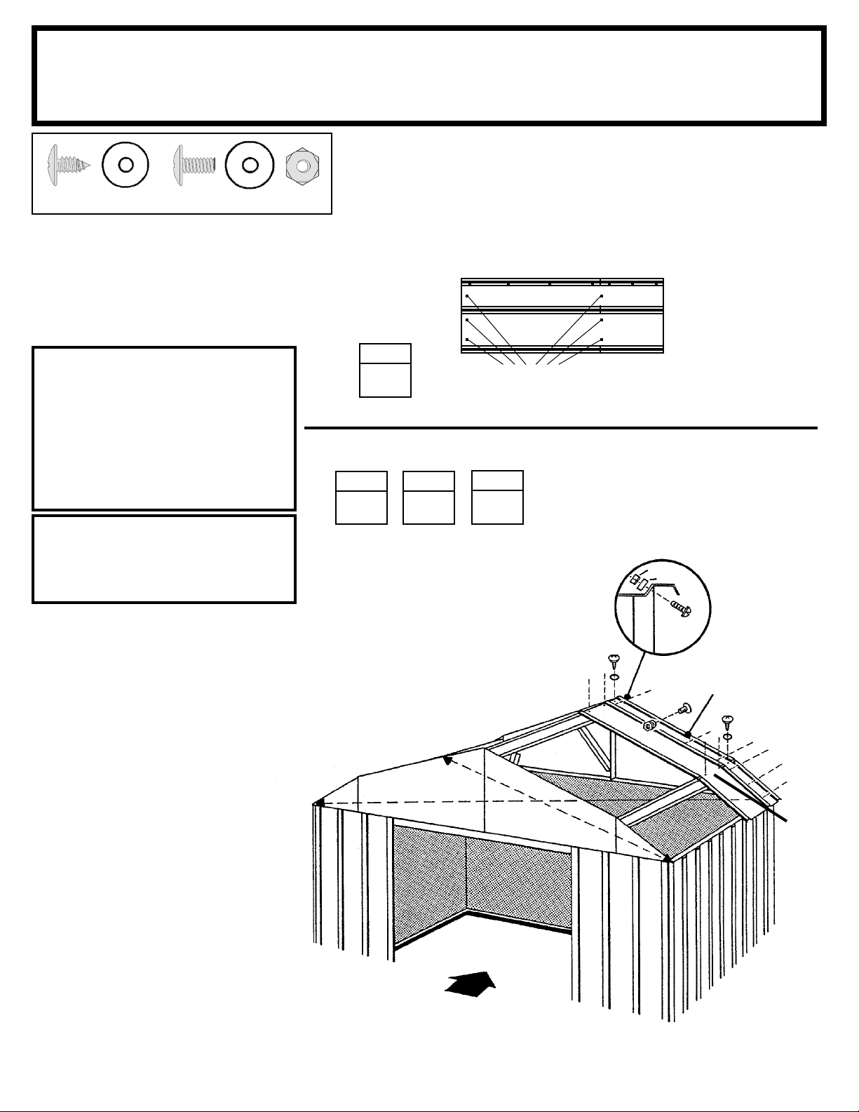
Step 14
SO27et ctr
(6) (7)
Installing the roof panels is best done
with a step ladder. Install the fi rst roof
panel at the back right corner of the
building. Each screw and bolt in the
roof requires a washer.
Parts Needed For
Right Roof Panel
6188 Right Roof Panel (1)
6188
NOTE
Measure the building diagonally
again and make adjustments to
make sure the building is square
and level. This will make the roof
panels fi t better, and holes will
align. Don't anchor the fl oor frame.
NOTE
If a Roof Beef-Up Kit was
purchased, assemble prior to at-
taching the roof panels.
1 Locate the roof panels and fi nd the
right roof panel part number 6188.
2 Position a right roof panel at the
back right corner and fasten to the
top roof beam using screws.
STEP
(6) Screws
STEP
4
STEP
2
1
STEP
3
Hint: Follow the fastener sequence
shown for proper alignment.
1 thru 3
Nut
Washer
Bolt
Gable
(7)
4
Right Roof Panel
6188
5
6
7
8
9
10
3 Remove edge trim from the left
gable under the roof panel.
4 Continue fastening the right roof
panel to the gable and lower roof
beam using screws, bolts and nuts as
shown. Do not fasten the lower end
of the panels to the side wall angles
at this time.
11
thru
13
FRONT
27
Page 28
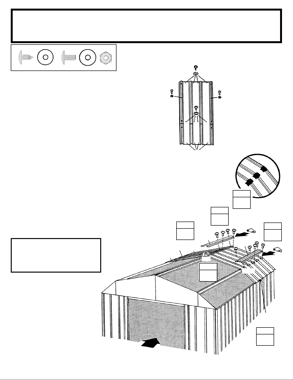
Step 15
SO28 ctr
(22)
(21)
Parts Needed For
Ridge Caps & Panels
6189 Left Roof Panel (1)
6538 Roof Panel (2)
6797 Ridge Cap (3)
Screws To
Roof Beam
1 Install a left roof panel 6189 at
the left rear corner of the roof.
2 Cut 34 short 3" (7,6 cm) strips off
the small roll of weather stripping
tape, and put them aside. Cover the
joint at the peak with weather stripping tape, large roll. Unroll the tape
and press it down over the opening
at the ridge as you install each roof
panel. Do not cut the tape at this time.
3 Install two roof panels 6538 work-
ing side to side. Fold the lower section
of the roof panels down. Cover the
notches with the strips of weather
stripping tape. Save the rest. Do not
fasten the lower end of the panels
to the side wall angles at this time.
Continue weather stripping the ridge
opening.
NOTE
Narrow roof panel crimped rib is
overlapped by wide rib of
adjacent panel where possible
4 Install three ridge caps 6797 on
the completed roof section using
bolts and nuts. Do not fasten the
ends of the ridge caps at this time.
Fasten at
Overlap With
Bolt
Screws To
Roof Beam
6538
Do not fasten
at this time
STEP
1
6797
6189
6797
Roll
STEP
2
Overlap With
STEP
4
Fasten At
Bolt
STEP
3
Weather Stripping Tape
STEP
5
6797
Strips
5 Fasten the roof panel ribs, peak
caps and ridge caps together using
bolts and nuts.
6538
STEP
3
FRONT
28
Page 29
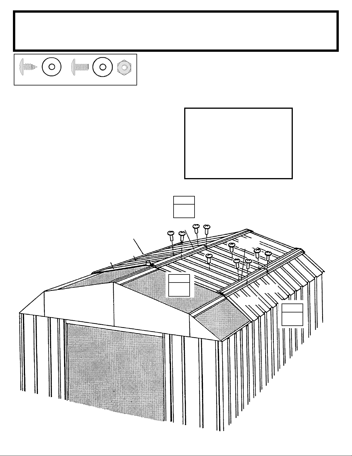
Step 16
SO29 ctr
Parts Needed For
Ridge Caps & Panels
6538 Roof Panel (4)
6869 Ridge Cap (3)
(32)
(16)
1 Install two roof panels 6538 work-
ing side to side. Cover the notched
areas of the roof panels with strips of
weather stripping tape and continue
weather stripping the ridge.
2 Install the second ridge caps 6869
overlapping the fi rst ridge caps.
Hint: The bolts on the ridge cap need
to be left loose to move the ridge cap
to the side and overlap the ribs of the
next roof panel.
3 Install two roof panels 6538 as
before working side to side while
fastening down ridge caps.
6538
NOTE
If roof beam holes do not line up
with the roof panel holes, shift the
building from left to right.
If this does not help, your building
may not be level. Shim the
corners until holes line up.
STEP
2
6869
6869
6869
6538
Weather Stripping Tape
STEP
3
29
6538
6538
STEP
1
Page 30
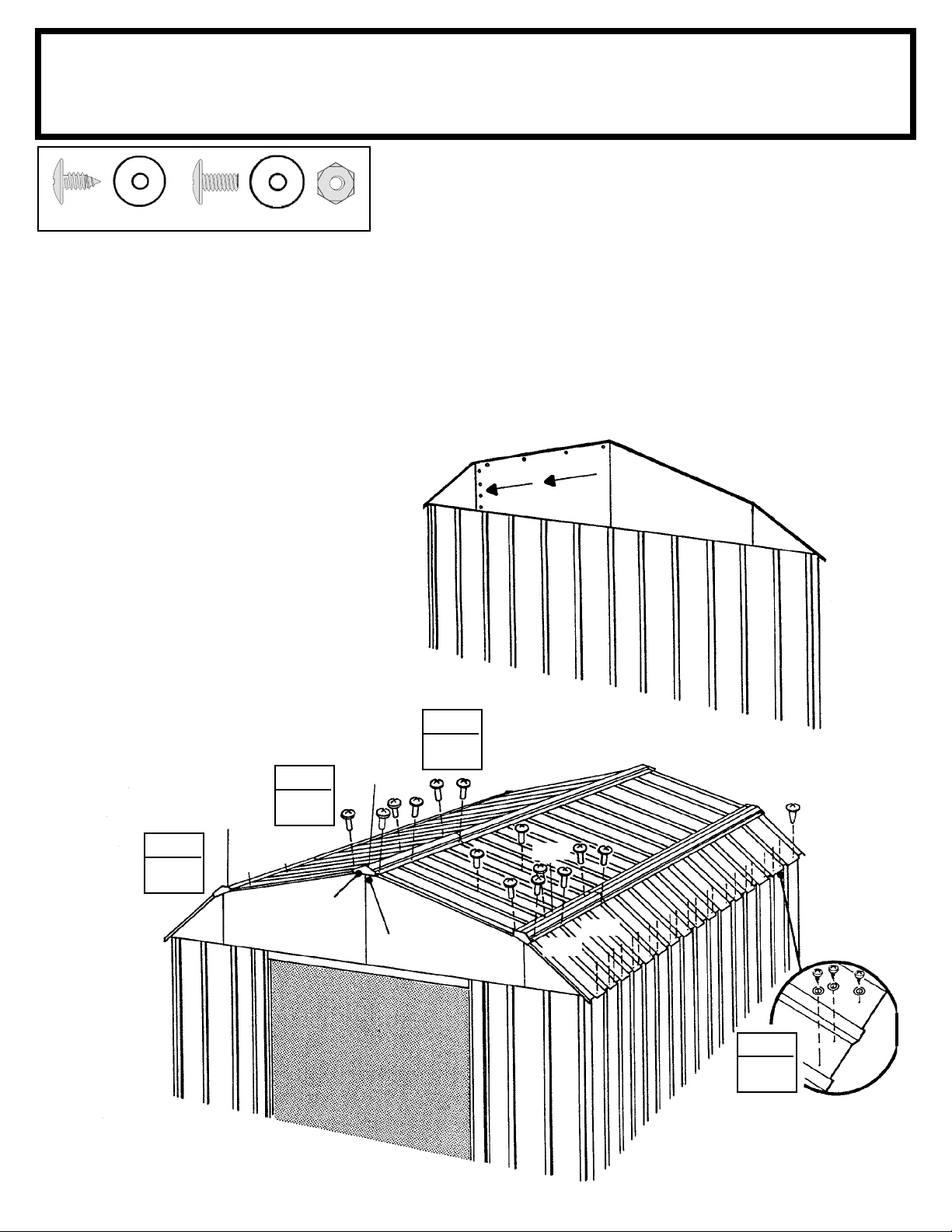
Step 17
SO30 ctr
Parts Needed For
Ridge Caps & Panels
6538 Roof Panel (2)
6797 Ridge Cap (3)
6188 Right Roof Panel (1)
6189 Left Roof Panel (1)
(72)
(36)
1 Install the third ridge caps 6797
overlapping the second ridge caps
while installing the remaining roof
panels 6538. Hint: The bolts on the
ridge cap need to be left loose to
move the ridge cap to the side and
overlap the ribs of the next roof panel.
Cover the notched areas of the roof
panels with strips of weather stripping
tape and continue weather stripping
the ridge.
2 Install the left 6189 and right roof
panel 6188 as you unroll the weather
stripping tape, and press it down.
Fasten the lower end of the panels
to the side wall angles using screws
and washers.
Reducing Large Gable Bulge
Loosen eight bolts and nuts shown. Apply
pressure with one hand at the peak of the
gable and tighten bolt #1. Keeping pressure
on the gable work down the slope tightening each bolt. Excess material will overlap
smaller gable at seam. Once material bulge
is worked out tighten four vertical bolts that
connect the large and small gables.
#1
#2
#3
#4
3 Fasten the roof panel ribs, peak
caps and ridge caps together using
bolts and nuts.
6797
STEP
3
6188
STEP
2
6538
Peak Cap
STEP
6797
Cut
Weather Stripping
and Fold Under
1
6797
6538
6189
STEP
2
30
Page 31
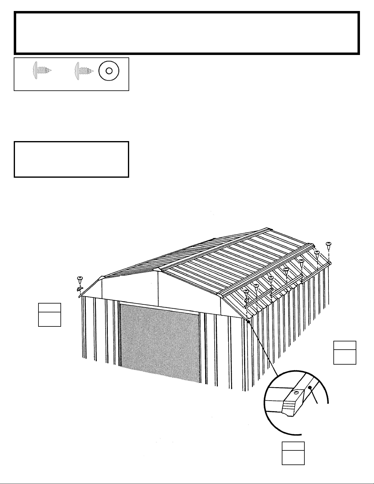
Step 18
SO31 ctr
(4) (10)
1 Attach the right, left and side
roof trim to the lower end of the roof
panels on each side of the building
using screws at each panel overlap.
NOTE
A single screw fastens both trim
pieces at the overlap.
2 Using your thumb and index fi nger,
overbend the bottom fl ange of the side
roof trim at the corner inward enough
so the right and left roof trim caps fi t
onto right and left corners.
Parts Needed For
Roof Trim
6893 Left Side Roof Trim (2)
6892 Right Side Roof Trim (2)
6015 Side Roof Trim (2)
3 Fasten the roof trim caps to the
side trim using a screw.
6892
Roof Trim Cap
STEP
3
6015
6893
6893
6015
Roof trim
Tuck Flange
Inward to Fit
Inside of
Roof Trim Cap
6892
STEP
1
31
STEP
2
Page 32
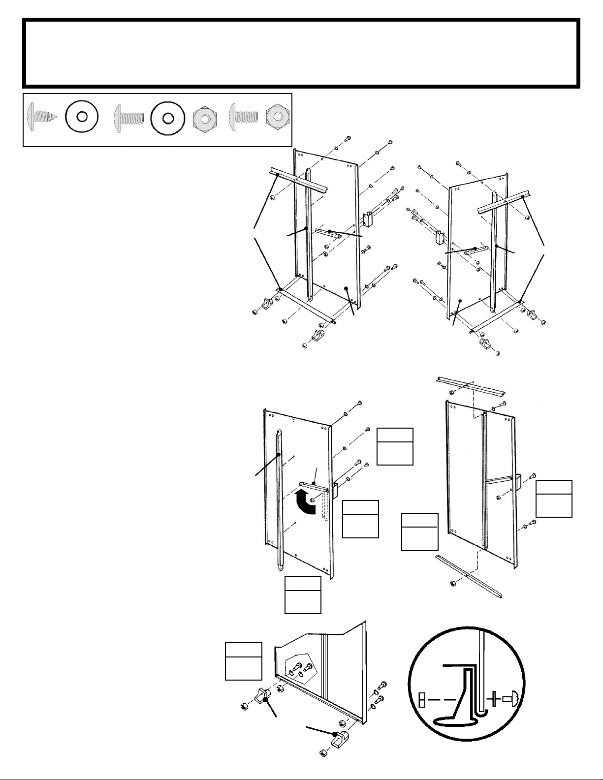
Step 19
SO32 ctr
Parts Needed For
Door Assembly
3719 Door Handle Brace (2)
10475 Right and Left Doors (2)
10497 Horizontal Door Brace (4)
6278 Vertical Door Brace (2)
(12)
The steps on this page tell how to
assemble the right door. You will perform exactly the same procedures for
the left door. Each bolt and screw in
the door requires a washer. Proceed
as follows:
1 Attach the door handle brace
and handle to the door with 1 bolt
as shown. Don't tighten the bolt yet.
2 Swing the door handle brace up
to the hole on the center of the door
and insert a screw.
3 Hold the vertical door brace
against the center of the inside surface of the door and turn the screw
to hold the vertical door brace and
door handle brace in place. Fasten
to door above and below center
connection using 2 screws.
4 Insert a second bolt in the door
handle and tighten both bolts.
5 Put a horizontal door brace onto
the top edge and bottom edge and
fasten with 1 bolt in the center.
6 Attach the lower door guides and
bolts as shown.
(4)(6)
10497
66382
6278
6278
66382
3719
STEP
3
66045
3719
10475
Right Door
66045
STEP
2
66045
STEP
1
STEP
5
END VIEW
SHOWING:
3719
10475
Left Door
10497
6278
66382
66382
10497
STEP
4
10497
7 Repeat steps 1 through 6 for the
left door.
STEP
6
66382
32
Horizontal
Door Brace
Guide
Door
Washer
Page 33
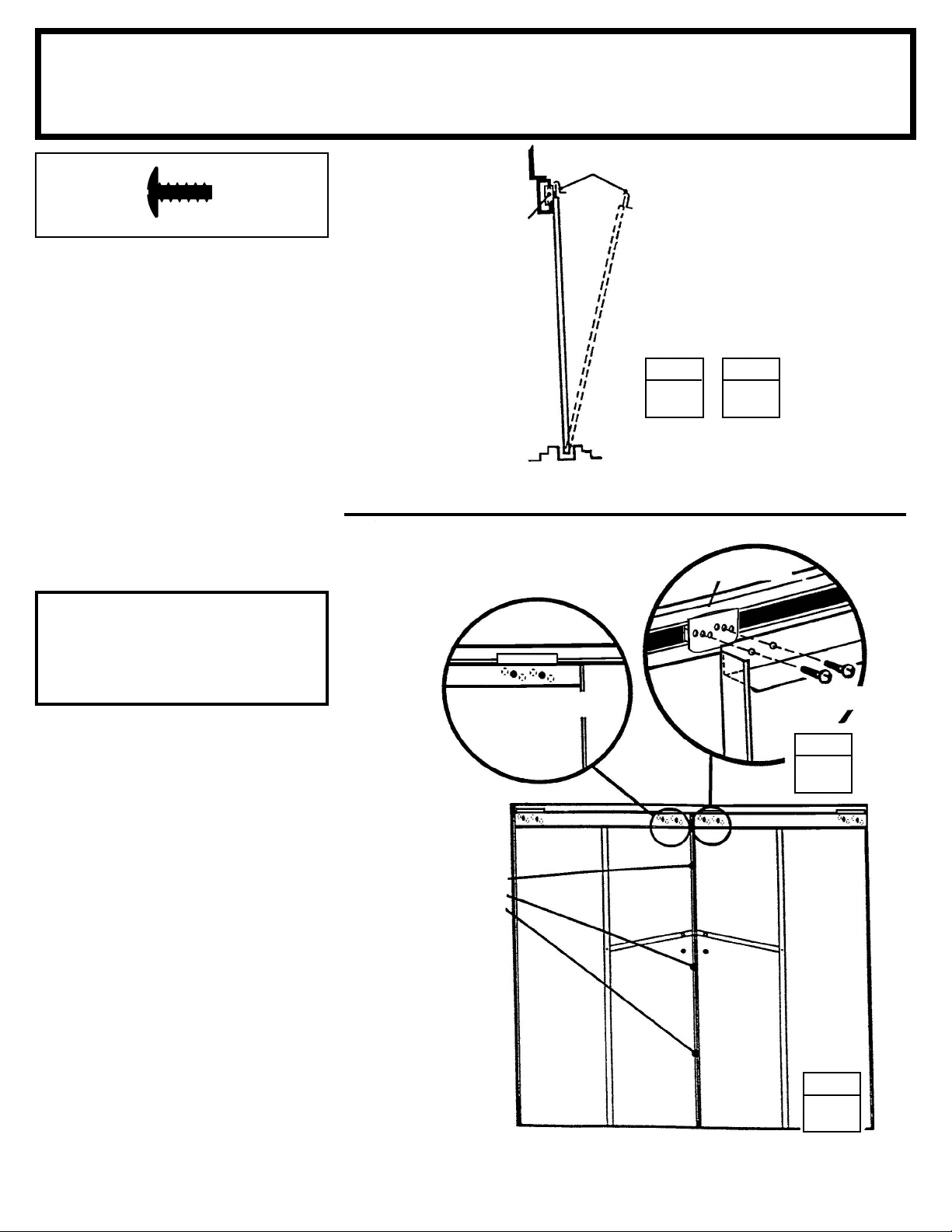
Step 20
SQ33 ctr
Parts Needed For
Door Installation & Adjustment
Right Door Assembly (1)
Left Door Assembly (1)
(8)
1 From inside the building, put the
bottom of the right door assembly
(on your left when you are inside the
building) behind door jamb into the
front frame track.
2 Position the top of the door so that
the holes in the door line up with the
holes in the door slides.
3 Fasten the door to the door slides
using two #10Bx1/2" (13 mm) screws
per door slide.
Gable
Door Track
Door Slide
Front Floor Frame Assembly
Horizontal Door Brace
Door
STEP
1
STEP
2
Door Slide
The holes in the door slides allow
you to adjust the doors. Place the
door in the middle holes.
NOTE
4 Repeat steps 1 through 3 for the
left door.
Adjustment Holes
Adjustment Holes Allow
Doors to Meet Evenly
Along Their Length
#10Bx1/2" (13 mm)
Screw
STEP
3
Right Door Left Door
STEP
4
Keep this Owner's Manual and Assembly Instructions for future reference.
33
Page 34
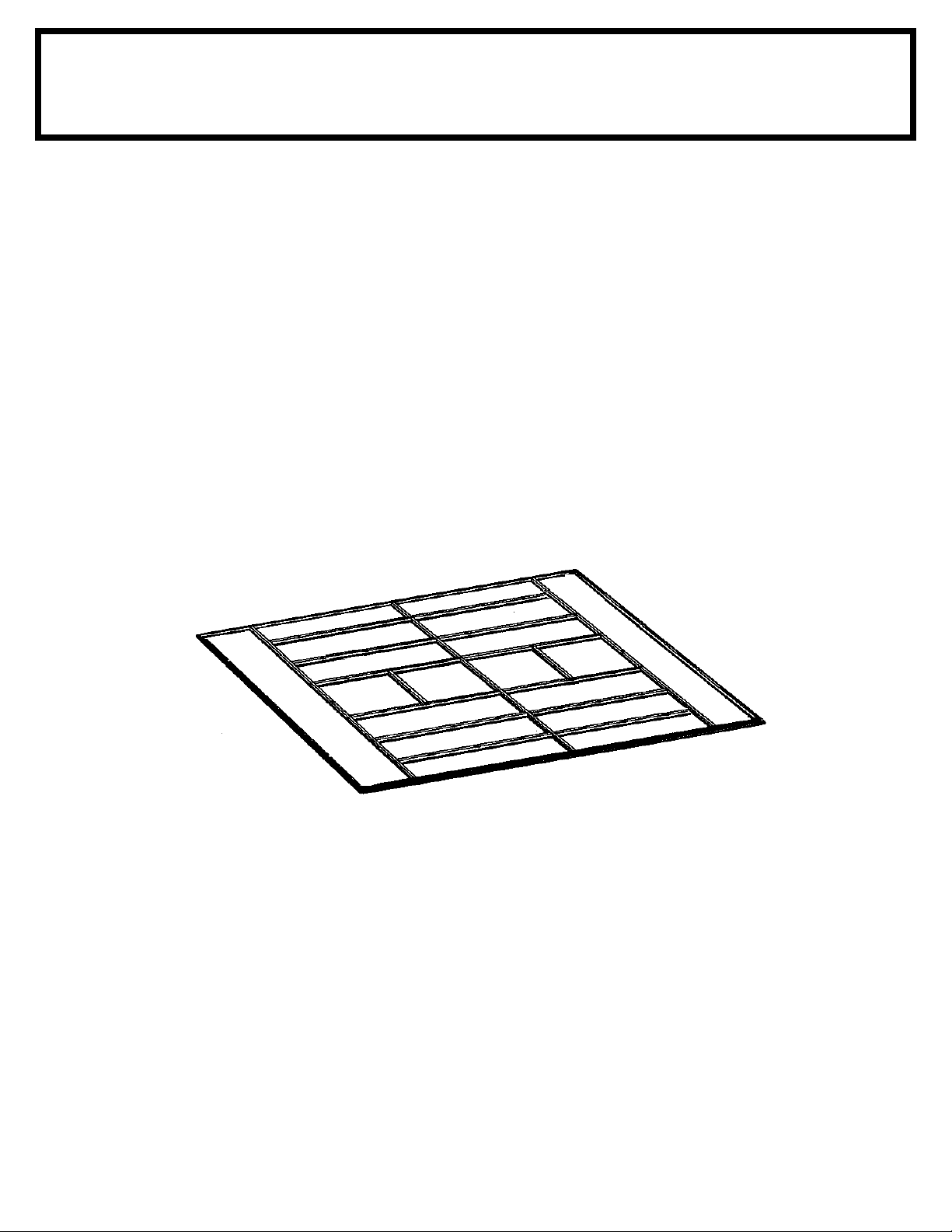
XA34
Anchoring
Anchor your building at this time.
Floor Frame
If you have purchased a Floor Frame Kit you need to install it at this time.
Anchoring and Floor Frame
Page 35
XA35
SOME FACTS ABOUT RUST
Rusting is a natural oxidizing process that occurs
when bare metal is exposed to moisture. Problem
areas include screw holes, unfi nished edges, or
where scrapes and nicks occur in the protective
coating through normal assembly, handling and use.
Identifying these natural rusting problem areas and
taking some simple rust protection precautions can
help to stop rust from developing, or stop it quickly
as soon as it appears.
SOME FACTS ABOUT RUST
1. Avoid nicking or scraping the coating surface,
inside and out.
2. Use all the washers supplied. In addition to
protecting against weather infi ltration, the washers
protect the metal from being scraped by the screws.
3. Keep roof, base perimeter and door tracks free of
debris and leaves which may accumulate and retain
moisture. These can do double damage since they
give off acid as they decay.
4. Touch up scrapes or nicks and any area of visible
rust as soon as possible. Make sure the surface is
free of moisture, oils, dirt or grime and then apply
an even fi lm of high quality touch-up paint.
Page 36
CO1014-C1 DK1014-B1 LX1014-C1 VS1014-C1 VY1014-A1
WV1014-C1 YT1014-C1 697.68604-A1 697.68630-A1 SG1014
SO36et
715831015
 Loading...