

Page 1
L-Series
®
L5
User Manual
September 2014
Page 2

© 2014 Arnold & Richter Cine Technik GmbH & Co. Betriebs KG. All rights reserved.
No part of this document may be used for distribution, reproduction, transmission, transcription, storage in a data retrieval system, or translated into any language in any form by any means without the prior written permission of ARRI®. If you are downloading files from our web pages for your personal use, make sure to check for updated versions. ARRI® cannot take any
liability whatsoever for downloaded files, as technical data are subject to change without notice.
L5.0002357, L02485
Page 3
Dimensions
3
Dimensions
Page 4

Content
Dimensions . . . . . . . . . . . . . . . . . . . . . . . . . . . . . . . . . . . . . . . . . . . . . . . . . . . . . . . . . . . . . . . . . . . . . . . . . . . 3
Safety Information . . . . . . . . . . . . . . . . . . . . . . . . . . . . . . . . . . . . . . . . . . . . . . . . . . . . . . . . . . . . . . . . . . . . . 6
Explanations of Warning Signs and Indications . . . . . . . . . . . . . . . . . . . . . . . . . . . . . . . . . . . . . . . . . . . . . . . . . . . . . . . . . .6
General Notes . . . . . . . . . . . . . . . . . . . . . . . . . . . . . . . . . . . . . . . . . . . . . . . . . . . . . . . . . . . . . . . . . . . . . . . . . . . . . . . . . . .6
General Safety Information . . . . . . . . . . . . . . . . . . . . . . . . . . . . . . . . . . . . . . . . . . . . . . . . . . . . . . . . . . . . . . . . . . . . . . . . .7
Specific Safety Information . . . . . . . . . . . . . . . . . . . . . . . . . . . . . . . . . . . . . . . . . . . . . . . . . . . . . . . . . . . . . . . . . . . . . . . . . .8
Maintenance Information . . . . . . . . . . . . . . . . . . . . . . . . . . . . . . . . . . . . . . . . . . . . . . . . . . . . . . . . . . . . . . . . . . . . . . . . . . .9
Legal disclaimer . . . . . . . . . . . . . . . . . . . . . . . . . . . . . . . . . . . . . . . . . . . . . . . . . . . . . . . . . . . . . . . . . . . . . . . . . . . . . . . . . .9
Introduction . . . . . . . . . . . . . . . . . . . . . . . . . . . . . . . . . . . . . . . . . . . . . . . . . . . . . . . . . . . . . . . . . . . . . . . . . 10
Features . . . . . . . . . . . . . . . . . . . . . . . . . . . . . . . . . . . . . . . . . . . . . . . . . . . . . . . . . . . . . . . . . . . . . . . . . . . . . . . . . . . . . . .10
Properties . . . . . . . . . . . . . . . . . . . . . . . . . . . . . . . . . . . . . . . . . . . . . . . . . . . . . . . . . . . . . . . . . . . . . . . . . . . . . . . . . . . . . .11
Unpacking . . . . . . . . . . . . . . . . . . . . . . . . . . . . . . . . . . . . . . . . . . . . . . . . . . . . . . . . . . . . . . . . . . . . . . . . . . . . . . . . . . . . .11
Overview . . . . . . . . . . . . . . . . . . . . . . . . . . . . . . . . . . . . . . . . . . . . . . . . . . . . . . . . . . . . . . . . . . . . . . . . . . . . 12
Physical Installation . . . . . . . . . . . . . . . . . . . . . . . . . . . . . . . . . . . . . . . . . . . . . . . . . . . . . . . . . . . . . . . . . . . 14
To adjust the stirrup . . . . . . . . . . . . . . . . . . . . . . . . . . . . . . . . . . . . . . . . . . . . . . . . . . . . . . . . . . . . . . . . . . . . . . . . . . . . . .14
To mount the spigot . . . . . . . . . . . . . . . . . . . . . . . . . . . . . . . . . . . . . . . . . . . . . . . . . . . . . . . . . . . . . . . . . . . . . . . . . . . . . .14
Basic features . . . . . . . . . . . . . . . . . . . . . . . . . . . . . . . . . . . . . . . . . . . . . . . . . . . . . . . . . . . . . . . . . . . . . . . . 16
Control options . . . . . . . . . . . . . . . . . . . . . . . . . . . . . . . . . . . . . . . . . . . . . . . . . . . . . . . . . . . . . . . . . . . . . . . . . . . . . . . . . .17
Connector Panel . . . . . . . . . . . . . . . . . . . . . . . . . . . . . . . . . . . . . . . . . . . . . . . . . . . . . . . . . . . . . . . . . . . . . . . . . . . . . . . . .17
Power . . . . . . . . . . . . . . . . . . . . . . . . . . . . . . . . . . . . . . . . . . . . . . . . . . . . . . . . . . . . . . . . . . . . . . . . . . . . . . 17
AC power . . . . . . . . . . . . . . . . . . . . . . . . . . . . . . . . . . . . . . . . . . . . . . . . . . . . . . . . . . . . . . . . . . . . . . . . . . . . . . . . . . . . . .17
To use a battery pack . . . . . . . . . . . . . . . . . . . . . . . . . . . . . . . . . . . . . . . . . . . . . . . . . . . . . . . . . . . . . . . . . . . . . . . . . . . . .18
Fixture menu . . . . . . . . . . . . . . . . . . . . . . . . . . . . . . . . . . . . . . . . . . . . . . . . . . . . . . . . . . . . . . . . . . . . . . . . . 19
Overview of the fixture menu . . . . . . . . . . . . . . . . . . . . . . . . . . . . . . . . . . . . . . . . . . . . . . . . . . . . . . . . . . . . . . . . . . . . . . .19
Features of the fixture menu . . . . . . . . . . . . . . . . . . . . . . . . . . . . . . . . . . . . . . . . . . . . . . . . . . . . . . . . . . . . . . . . . . . . . . .19
To read out fixture information . . . . . . . . . . . . . . . . . . . . . . . . . . . . . . . . . . . . . . . . . . . . . . . . . . . . . . . . . . . . . . . . . . . . . .23
Page 5

Short cuts . . . . . . . . . . . . . . . . . . . . . . . . . . . . . . . . . . . . . . . . . . . . . . . . . . . . . . . . . . . . . . . . . . . . . . . . . . . . . . . . . . . . . .24
DMX control . . . . . . . . . . . . . . . . . . . . . . . . . . . . . . . . . . . . . . . . . . . . . . . . . . . . . . . . . . . . . . . . . . . . . . . . . 25
DMX mode . . . . . . . . . . . . . . . . . . . . . . . . . . . . . . . . . . . . . . . . . . . . . . . . . . . . . . . . . . . . . . . . . . . . . . . . . . . . . . . . . . . . .25
DMX data link . . . . . . . . . . . . . . . . . . . . . . . . . . . . . . . . . . . . . . . . . . . . . . . . . . . . . . . . . . . . . . . . . . . . . . . . 26
Tips for reliable data transmission . . . . . . . . . . . . . . . . . . . . . . . . . . . . . . . . . . . . . . . . . . . . . . . . . . . . . . . . . . . . . . . . . . .26
To connect the data link . . . . . . . . . . . . . . . . . . . . . . . . . . . . . . . . . . . . . . . . . . . . . . . . . . . . . . . . . . . . . . . . . . . . . . . . . . .26
Fixture Menu . . . . . . . . . . . . . . . . . . . . . . . . . . . . . . . . . . . . . . . . . . . . . . . . . . . . . . . . . . . . . . . . . . . . . . . . . 27
Status Messages . . . . . . . . . . . . . . . . . . . . . . . . . . . . . . . . . . . . . . . . . . . . . . . . . . . . . . . . . . . . . . . . . . . . . . . . . . . . . . . .28
Fixture Menu . . . . . . . . . . . . . . . . . . . . . . . . . . . . . . . . . . . . . . . . . . . . . . . . . . . . . . . . . . . . . . . . . . . . . . . . . . . . . . . . . . .29
RDM commands . . . . . . . . . . . . . . . . . . . . . . . . . . . . . . . . . . . . . . . . . . . . . . . . . . . . . . . . . . . . . . . . . . . . . . 30
Required RDM command extensions . . . . . . . . . . . . . . . . . . . . . . . . . . . . . . . . . . . . . . . . . . . . . . . . . . . . . . . . . . . . . . . . .31
Manufacturer commands . . . . . . . . . . . . . . . . . . . . . . . . . . . . . . . . . . . . . . . . . . . . . . . . . . . . . . . . . . . . . . . . . . . . . . . . . .33
LSeries Manager . . . . . . . . . . . . . . . . . . . . . . . . . . . . . . . . . . . . . . . . . . . . . . . . . . . . . . . . . . . . . . . . . . . . . 33
Error messages . . . . . . . . . . . . . . . . . . . . . . . . . . . . . . . . . . . . . . . . . . . . . . . . . . . . . . . . . . . . . . . . . . . . . . 34
DMX protocol . . . . . . . . . . . . . . . . . . . . . . . . . . . . . . . . . . . . . . . . . . . . . . . . . . . . . . . . . . . . . . . . . . . . . . . . 36
ARRI L5-TT (Tungsten Tuneable) . . . . . . . . . . . . . . . . . . . . . . . . . . . . . . . . . . . . . . . . . . . . . . . . . . . . . . . . . . . . . . . . . . .36
ARRI L5-DT (Daylight Tuneable) . . . . . . . . . . . . . . . . . . . . . . . . . . . . . . . . . . . . . . . . . . . . . . . . . . . . . . . . . . . . . . . . . . . .38
ARRI L5-C . . . . . . . . . . . . . . . . . . . . . . . . . . . . . . . . . . . . . . . . . . . . . . . . . . . . . . . . . . . . . . . . . . . . . . . . . . . . . . . . . . . . .40
Specifications . . . . . . . . . . . . . . . . . . . . . . . . . . . . . . . . . . . . . . . . . . . . . . . . . . . . . . . . . . . . . . . . . . . . . . . . 48
Page 6
Safety Information
6
Safety Information
Always follow these instructions to protect against
injury to yourself and damage to the product or other
objects.
Explanations of Warning Signs and Indications
Possible risk of injury or damage to equipment.
Risk of fire or electric shock. Possible risk of injury or
damage to equipment.
Caution! Hot surface. Possible high surface temperature. Risk of injury through burns.
Caution! High intensity light emission. Risk of eye
injury.
Note: Indicates further information.
General Notes
• This document contains important instructions and notes to
handle the product safe.
• Always follow all safety information for your own protection.
• Please follow the user manual of accessories and third party
accessories for the L5-Series such as battery packs and battery chargers. They contain important safety and security information.
• Retain this user manual for further reference and possible
new owners of this product.
• ARRI
®
L-Series® products are intended for professional use
and may only be operated by qualified persons. They are not
for household use.
• Help protecting the environment by disposing the package
material at your local recycling center.
• All components comply to the guidelines listed below:
Low voltage directive 2014/35/EU
EMC directive 2014/30/EU
RoHS directive 2011/65/EU
Page 7
Safety Information
7
General Safety Information
Read and understand all safety information and operation instructions before you operate or install the
product.
Use only genuine spare parts or accessories that
have been recommended or approved by ARRI.
Other accessories or spare parts may cause hazards,
damage the product or invalidate the warranty.
Check all cables and devices for visible damage
before you work with the system. Defective electric or
electronic devices must not be used. Take special
care of the following components:
In the event of visible damage to the product or
accessory, the product or accessory must no longer
be used. Replace or repair the respective part. In
case of repairs, please contact an authorized ARRI
service center.
Never attempt to repair any part of the product on
your own. Maintenance and repair work is only to be
carried out by authorized ARRI service centers.
Do not operate the product if the ambient temperature exceeds 45° C (113° F). Do not expose the product to rain or moisture. Observe all information given
in chapter “Specifications” on page 48.
Do not bypass any safety feature of the product.
Do not open the product. There are no user serviceable parts inside. The housing is sealed with an adhesive seal that will break immediately when trying to
open the housing. Doing so will invalidate the warranty.
In addition to regular visible checks ARRI recommends that all electric components are checked for
electrical safety by a professional every 12 month.
Keep the protocol of the check.
Component Possible damage
Housing,lens Cracks,cuts,deformation
Cables Cuts,deformation,burns
Connectors Cracks,deformation,burns
Cableconnectors Damaged
Innerthreads Overwound
Page 8
Safety Information
8
Specific Safety Information
Intensive use can cause the surface and the heat sink
to become hot. Let the product cool down complete
before you handle it.
Never cover air vents and the heat sink during operation. Keep a minimum clearance around the product
of 0.5 m (1.65 ft).
WARNING: Intense light. The product is equipped
with high intensity LEDs which emit at high luminance
levels. Never look direct into the light source.
Never point a light beam from another luminaire into
the light source. Do not place the product on heat
sources. Intense heat cause automatic power off during operation.
Devices and accessories must be secured against fall
when mounted above floor level. Always observe
common and local safety regulations.
Never use the cables for transportation. Never hang
the product on its cables. Do not hang a battery pack
on its connection cable to the product.
CAUTION: High voltage! Always disconnect the product complete from mains voltage before you connect
or disconnect a cable or replace the fuse of the product.
Always check that the local AC power matches the
voltage and frequency range printed on the type label
of the product before use. Never use the product
when the AC power does not match.
Always check that the supply voltage of the battery
pack matches the voltage range printed on the type
label of the product before use.
Never connect the product to a dimmer-system or a
dimmer-channel in non-dim mode. To do so will damage the electronics. Damages caused by connecting
the product to a not suitable power source are not
covered by the warranty.
Never bypass any fuse.
Always keep cables away from the product during
operation. Do not tilt the power cable directly after the
connector. Water could immerse and cause short circuits and damage the connector.
Disconnect all cables prior to transport.
Page 9

Safety Information
9
Not to observe these safety information or to ignore common
sense may cause serious injury or even death. Damage to the
product or other devices is possible.
Please observe the information given in the „Safety leaflet
ARRI lampheads“ (L5.40731.E). The leaflet is available for
download on our web site www.arri.com.
Maintenance Information
• Do not clean the surface of the product with solvents or strong
detergents.
• Clean the product with a soft cloth wetted with a mild detergent. Do not rub the surface: lift stuck particles off with a soft
repeated press.
• Clean soiled electric contacts with cotton swabs wetted with
isopropyl alcohol.
• Keep electric contacts clean and replace corroded parts.
Legal disclaimer
© 2014 Arnold & Richter Cine Technik GmbH & Co. Betriebs
KG (ARRI). All rights reserved. Information subject to change
without notice. ARRI and all affiliated companies disclaim liability for any injury, damage, direct or indirect loss, consequential
or economic loss or any other loss occasioned by the use of,
inability to use or reliance on the information contained in this
document. The ARRI logo, the ARRI name and all other trademarks in this document pertaining to services or products by
ARRI or its affiliates and subsidiaries are trademarks or licensed by ARRI or its affiliates or subsidiaries.
ARRI and the ARRI logo are registered trademarks of the
Arnold & Richter Cine Technik GmbH & Co. Betriebs KG.
Page 10

Introduction
10
Introduction
Thank you for selecting a LED luminaire of the L-Series from
ARRI. The ARRI L5 are fresnel-luminaires equipped with a
high precision, micro-processor controlled LED light source.
The ARRI L5 is a perfect and easy replacement for conventional fresnel-luminaires with tungsten lamps.
The L5-Series combines the advantages of the LED technology with the ease of use of a traditional fresnel-luminaire. The
L5-Series integrates seamless into established working practice. LED luminaires are much more efficient than light sources
with conventional tungsten lamps. The optical system offers
real fresnel characteristics with an extreme smooth beam and
clean shadows. The half peak angle can be adjusted continuously from 15° - 50°.
The ARRI L5 emits white or colored light with adjustable color
temperature and adjustable green / magenta saturation.
Please find more detailed information in chapter “Specifications” on page 48. The light spectrum is optimized for excellent
color rendition and fulfills perfect the demands of modern, digital cameras. All models of the ARRI L5 can be controlled using
the common DMX512-A protocol or the fixture menu.
The ARRI L5 can be powered by AC power, low voltage DC
power sources and battery packs. Please find more detailed information about the use of battery packs in the section “Power”
on page 17.
Features
Focus
Traditional fresnel-luminaires are able to spot and flood the
beam as needed. Whether it is a flood field for a pullback or a
tight spot for a bright highlight, the continuous focusability of
the ARRI L5 performs just as expected.
Versatile beam characteristics
The ARRI L5 provides the same ability as conventional fresnelluminaires to cut set elements and shape the beam with barndoors and flags.
Even light field
Clean, defined shadows have traditionally been a trait only of
single source tungsten and daylight fixtures. ARRI L5 fresnelluminaires provide the same single shadow properties lighting
designers expect, delivering natural results.
Vibrant colors, full spectrum lighting
True-to-life color rendition is an outstanding feature of the
ARRI L5, comparable to a full spectrum tungsten source. The
fully tuneable white light of the ARRI L5-C can be adjusted for
different skin tones, camera sensors and mixed light environments. Full gamut color mixing enables the rendition of all color
shades, making color filters dispensible.
Cool light beam
Like all LED light sources the ARRI L5 does not emit infrared
or UV radiation and thus does not forward heat, making actors
feel comfortable in the light beam.
Page 11

Introduction
11
Properties
Focus knob
The TRUE BLUE
®
style focus knobs provide precise adjustment and rapid flood-to-spot with only three turns. Knobs on
both sides of the fixture ensure easy access from all positions.
Sliding stirrup
The sliding stirrup design enables precise compensation for
front end accessories.
Yoke
With an extreme slim profile, the extruded aluminum yoke provides high strength without added weight. An optional, pole operated yoke allows full operation of pan and tilt from the floor
and is therefore a popular choice for many studios.
Tilt-lock
The high strength tilt-lock provides extreme secure locking. It
eliminates movement and slippage and ensures that the fixtures will stay where you put them.
DMX-control
All functions of the ARRI L5 are controllable through DMX. The
ARRI L5 is also fully RDM compatible and is equipped with a
feedback channel for reporting all set parameters including
system status.
Fixture menu
For location applications the ARRI L5 is equipped with a fixture
menu for manual adjustment of intensity, color temperature
and plus/minus green as well as hue and saturation (functions
available depending on type).
Unpacking
The ARRI L5 is supplied with:
• Power cable with power plug or bare ends
• Stirrup
• Short 28 mm spigot with 16 mm hole (mounted on
p.o. stirrups)
• Short instructions
Please refer to chapter “Accessories” on page 49 for more information about optional accessories.
Page 12
Overview
12
Overview
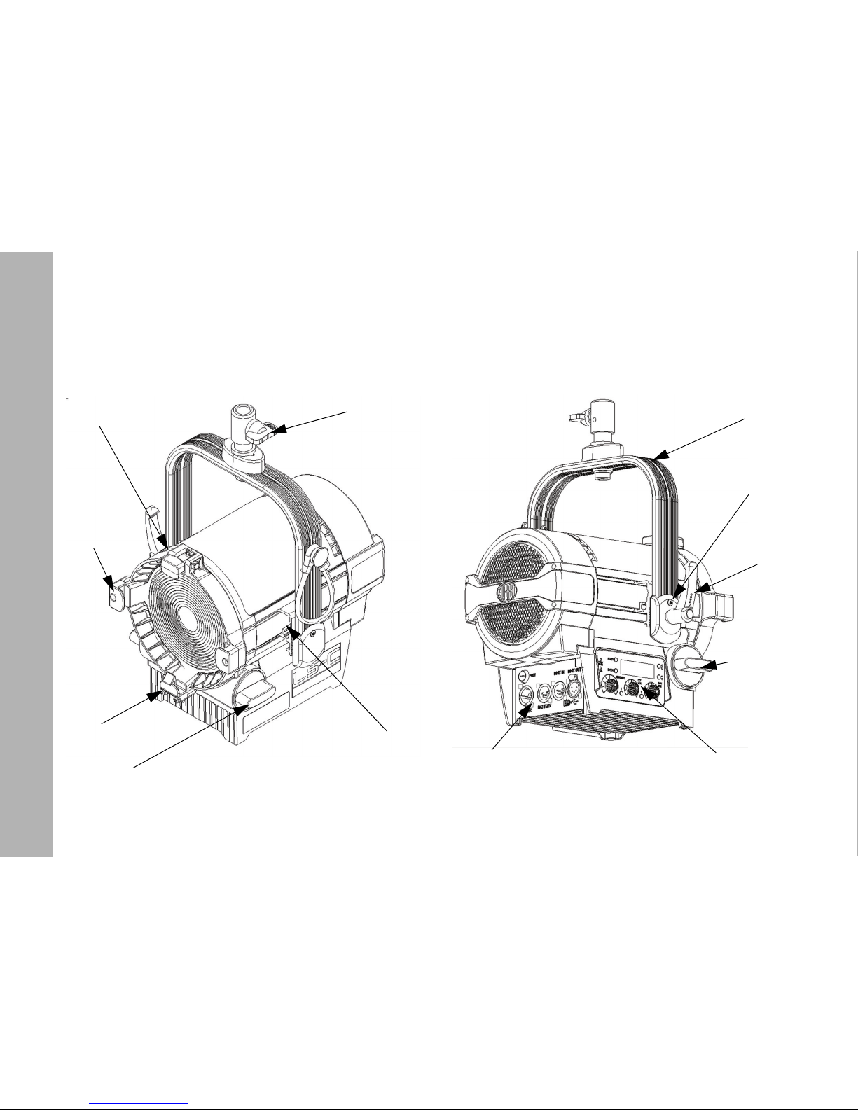
Stirrupbracket
Spigot
Toplatch
Safetycatch
Focosknob
Latch
Stirrup
Tiltlock
Tiltlock
Focsknob
Fixturemenu
Connectors
lever
Page 13
Overview
13
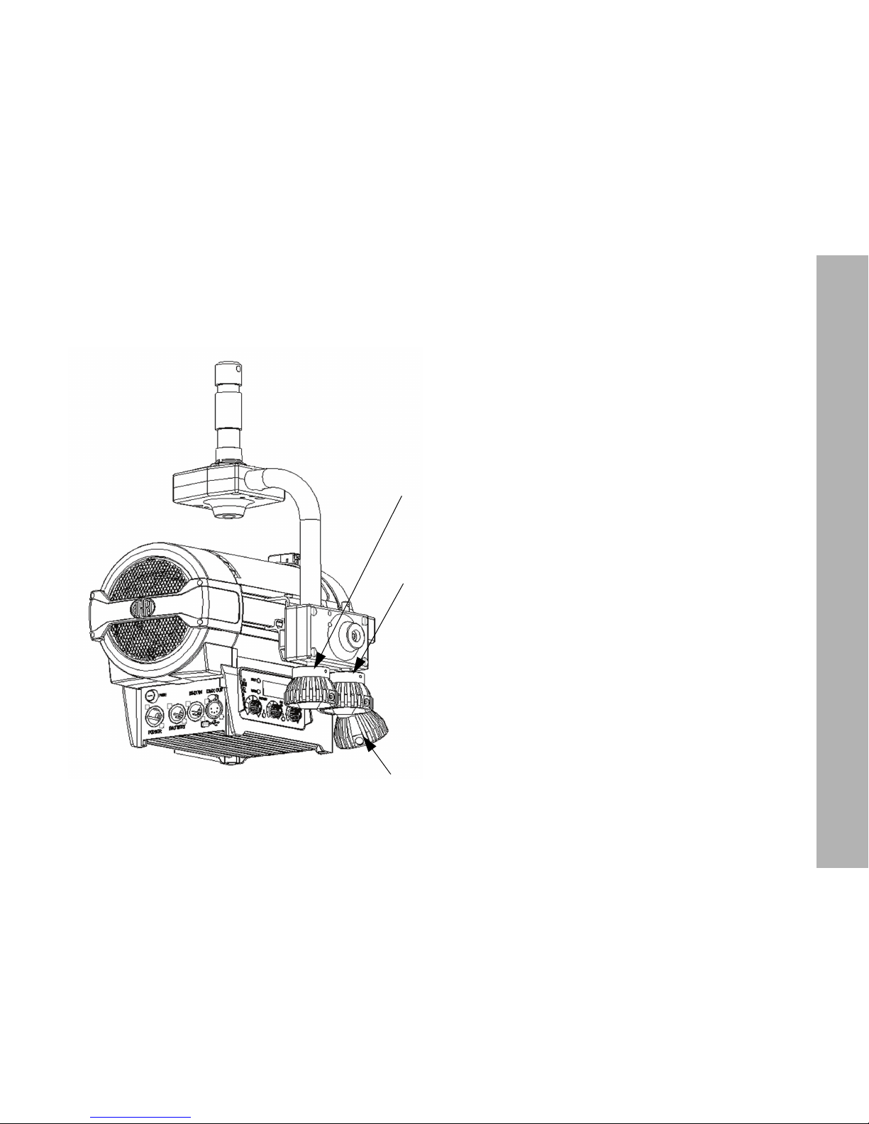
Pan
Tilt
Focus
Page 14
Physical Installation
14
Physical Installation
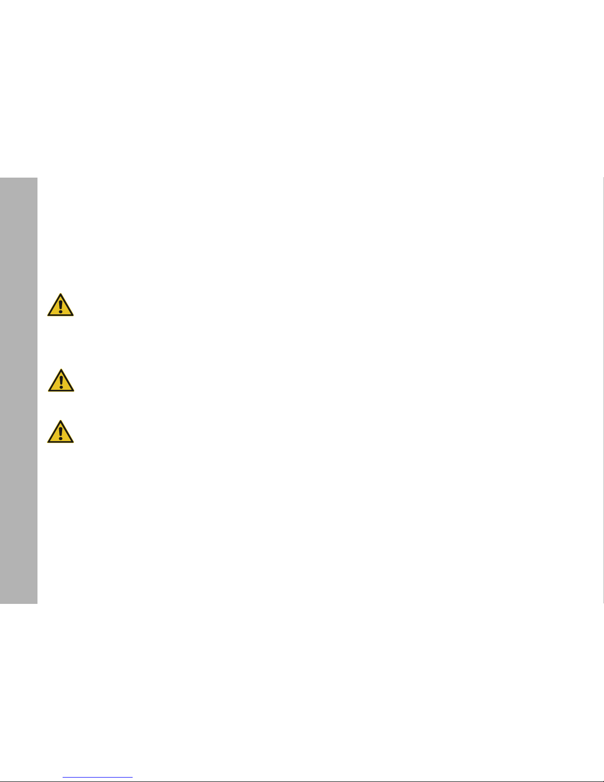
WARNING! Attach an approved safety-cable to
secure the product against clamp or bracket failure.
Lead the safety-cable through the stirrup (or the eyelet when using a P.O. version) and keep it as short as
possible. The safety-cable needs to be approved at
least 10 times the weight of the product including all
accessories mounted at the product. Secure all
accessories mounted at the product with additional
safety-cables to protect them from fall down and
cause injuries and damages.
WARNING! The rigging structure needs to be
approved for at least 10 times the weight of all
devices, equipment and cables installed on it.
IMPORTANT! Do not illuminate the display and the
fresnel-lens by high power light beams from a short
distance. The display and the light engine are damaged by high brightness and heat radiation within
very short time.
To adjust the stirrup
You need
• a Torx20 screw driver,
• a 10 mm allen key and
• a torque wrench (37 ft-lbs)
to adjust the stirrup.
On delivery the stirrup is in the basic position (tilted back).
Loosen the Torx20 screws on both sides of the stirrup bracket
slightly and pull the stirrup bracket towards the rear of the product. Loosen the lever of the tilt-lock and tilt the stirrup
upwards.
Slide the stirrup to the point of balance. The point of balance is
dependent on the accessories mounted at the product. Tighten
both Torx20 screws of the stirrup brackets. Do not overtighten
the screws. Tilt the stirrup to the desired position and tighten
the tilt-lock by using the lever. For better leverage, press the
knob on the tilt-lock-lever and turn the lever to the desired position.
To mount the spigot
Place the spigot and the distance plate on the 13 mm hole in
the middle of the stirrup. Insert the allen screw with washer and
spring washer and tighten it with a torque wrench to 37 ft-lbs
torque.
Page 15
Physical Installation
15
To mount the device
Always observe all safety information listed in chapter “Physical Installation” on page 14 when you mount the product and
accessories:
Be aware of the maximum tilt angle 90° upwards and 90° downwards.
Ensure that you install all accessories correct when you mount
the product above floor level:
• Top latched locked, safety catch snapped in.
• Set up tripods in a stable position. Tripods need to be approved for the load they need to carry.
• Always observe the additional load of cables and accessories!
ATTENTION! Lateral load can cause deformation or
breaking of the spigot and the stirrup!
Please observe the information given in the „Safety
leaflet ARRI lampheads“ (L5.40731.E), which is available for
download on our web site www.arri.com.
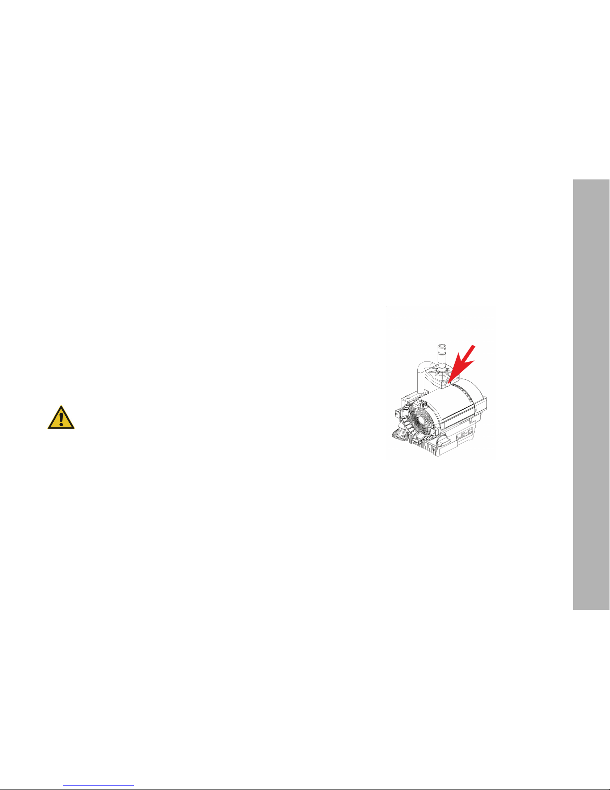
To mount the safety cable at the p.o. stirrup
Lead the safety-cable through the eye bolt at the p.o. stirrup as
shown in the illustration below.
Keep the safety-cable as short as possible. Do not limit the
range of movement of the product.
Page 16

Basic features
16
Basic features
Pan and tilt
Loose the mounting screw of the tripod or the appropriate fixing
screw of the mounting clamp to pan the product. Tighten the
screw to avoid unintended movement. Loose the tilt-lock to tilt
the product to the desired angle. Tighten the tilt-lock-lever to
avoid unintended movement.
To adjust the beam angle
Turn one of the focus knobs beneath the lens tube to adjust the
beam angle continuously. The entire lens tube moves in and
out. Two mechanisms protect the product from being damaged:
• A predetermined braking point prevents the product from
damage, when the focus knob is turned with too high torque
at either end of the focus range.
• The self-impeding focus gear prevents the lens tube to move
itself in or out when the product is operated in a tilted position.
Use of accessories for beam shaping and light design
You can mount accessories such as a barndoor, filter holder or
scrim on the front side of the product:
• Firmly press the button at the side of the top latch to open the
top latch.
• Insert the accessory from the upside into the brackets until the
safety catch engages. Slightly tilt the safety catch with your
finger for support.
• Close the top latch. Make sure that the hook of the top latch
engages into the holding ring of the accessory.
DMX/RDM-interface
The product has a DMX/RDM-interface. It has 5-pin XLR connectors for DMX/RDM data input and output. Please find more
detailed information to establish a DMX/RDM data-link in chapter “DMX data link” on page 26.
USB-interface
The product has a mini-USB connector to upload firmware and
set parameters. The USB-interface can be used for service
purpose like download error reports and set certain data. To do
so you need a software tool, the „L-Series manager“. Download it free of charge from the ARRI web site www.arri.com.
Please find more detailed information to work with the L-Series
manager in the user manual of the software. The manual is included in the download package.
Turn on and use the product
Turn on the power switch or connect the product to AC power.
The product initializes for some seconds and is ready for operation. The product will operate with the settings made on the
fixture menu or received by DMX. Please observe the following
section to use the product.
Page 17
Power
17
Control options
You can set up or control the product with the options listed in
the table below:
Connector Panel
Power
WARNING! For protection from electric shock, always
connect the product electrically to ground (earth)
when connected to AC power. The AC mains power
supply must be fitted with a fuse or circuit breaker
and ground-fault (earth-fault) protection.
IMPORTANT! Ensure that persons do not look at the
light emission aperture when the product is connected to AC power or a battery pack. The product
can light up suddenly. The high intensity of the
ARRI L5 can cause eye irritation or injury when not
respecting the safety distance.
IMPORTANT! Always connect the ARRI L5 direct to
AC power. Do not connect it to a dimmer-system.
Doing so will damage the product.
AC power
The products of the ARRI L5 has an auto-sensing switch-mode
power supply that automatically adapts to AC power
at 90 - 264 V ~, 45 - 65 Hz (nom.).
Before you connect the product to AC power or a battery pack,
check that:
• the dimmer knob at the fixture menu is set to 0%, and
• no DMX signal is present at the DMX-input of the ARRI L5.
Option Control Configuration Information
Fixture menu yes yes page 19
DMX yes no page 25
RDM yes yes page 30
LS Manager no yes page 33
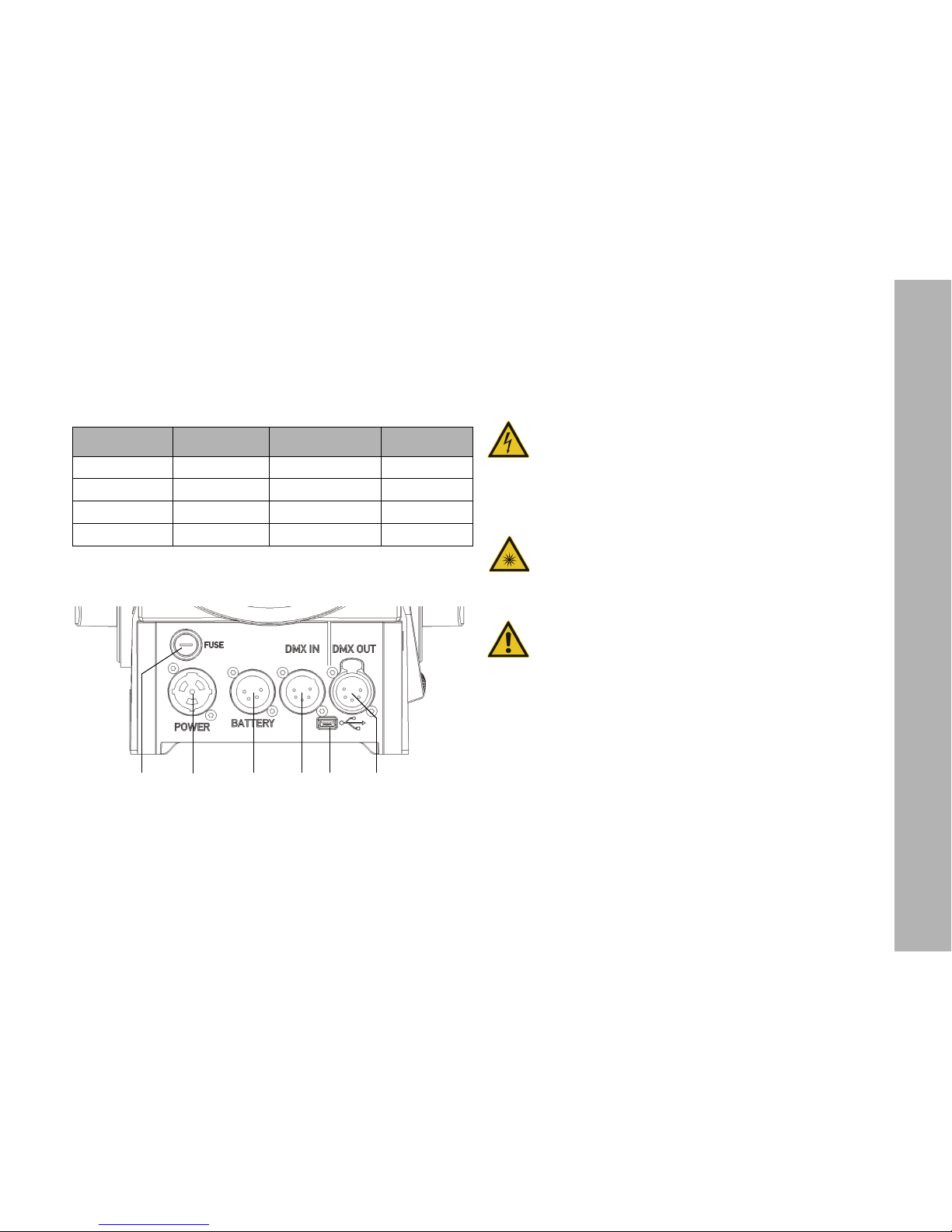
1Fuseholder
2ACpowerin
3Connectorforbatterypack
4DMXinput
5DMXoutput
6USBconnector
1
3
4
56
2
Page 18
Power
18
You can hard-wire the ARRI L5 to a building electrical installation. You can install a power plug that is suitable for the local
power outlets on the power cable. Socket outlets or external
power switches that supply the product with power must be located near the product and easily accessible so that the product can easily be disconnected from power.
The ARRI L5 requires a power input cable with a Neutrik
®
PowerCON® True1 NAC3FX-W cable connector. Cable
requirements are listed in chapter “Specifications” on page 48.
ARRI offers power cables with PowerCON® cable connectors
and different plugs or bare ends (see “Accessories” on
page 49).
To insert and remove the PowerCON
®
cable connector
• Line up the raised key of the connector and the keyway of the
input socket. Insert the cable connector without force in the
power input socket.
To lock the cable connector:
• Turn it a full quarter-turn clockwise.
To unlock the cable connector:
• Push the connector lock backwards and turn the cable connector counter-clockwise. Pull the cable connector out of the
power input socket.
To use a battery pack
The ARRI L5 can be powered independently from AC power
with a battery pack.
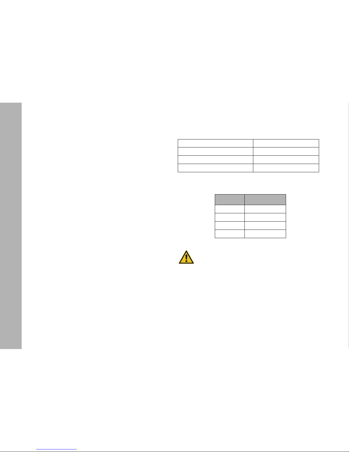
The battery pack must meet the following requirements:
The product has a 4-pin XLR male connector for battery power
and DMX data input. The pin-out is:
IMPORTANT! Check that the pin-out of the battery
pack matches the pin-out of the product. Wrong
assigned pin-outs damage the ARRI L5 and / or the
battery pack.
Always follow the safety information for the battery pack. Use
only battery packs that meet all requirements listed above. The
use of battery packs that do not fulfill the requirements damage
the product and / or the battery pack.
Note: The ARRI L5 switches off when the battery voltage drops
below 22 V=. The product will be damaged, when the battery
voltage exceeds 45 V=.
Output voltage 23 - 36 V=
Battery operating temperature 68° F - 113° F
Minimum capacity 5,5 Ah
Power outlet connector 4-pin XLR connector
Pin Assignment
1 0 V
2 Data -
3 Data +
4 + 23 V - 36 V=
Page 19
Fixture menu
19
To insert and remove the 4-pin XLR cable connector
To insert the 4-pin XLR cable connector:
• The main switch of the battery pack must be turned off,
if possible.
• Align the raised key of the cable connector with the keyway of
the input socket. Insert the cable connector without force in
the input socket.
• The cable connector must lock. Repair or replace cable connectors that do not lock.
To remove the 4-pin XLR cable connector:
• Switch of the battery pack, if possible.
• Press down the locking pin of the cable connector and remove
the cable connector.
Tips for the use of battery packs
The ARRI L5 draws 115 W power at full intensity. Use the following rule of thumb to calculate the likely operating time with
a fully charged battery pack at constantly 100% brightness:
It is not possible to calculate the operating time exactly when
brightness changes often. The possible operating time is dependent from age, state of charge and type of the battery pack.
Fixture menu
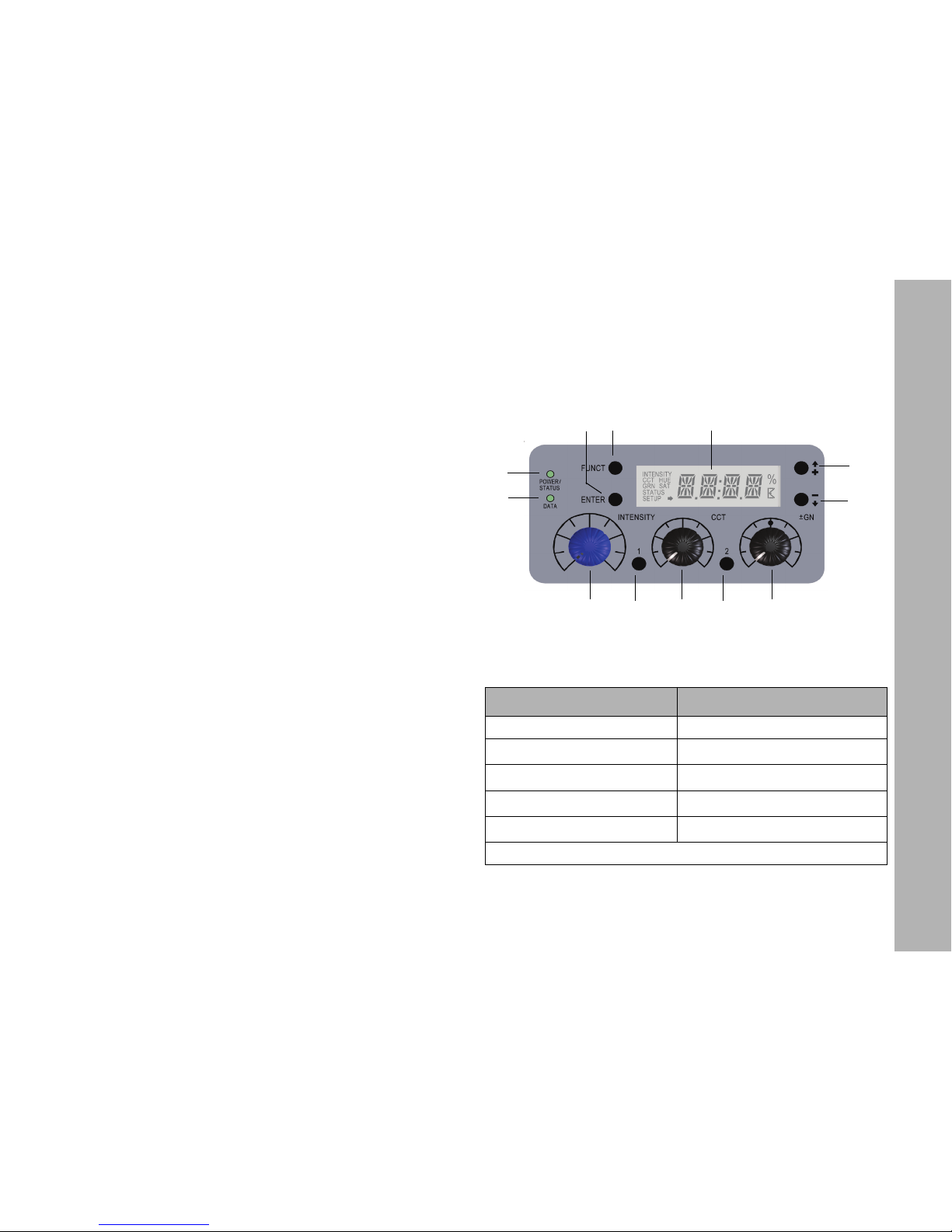
Overview of the fixture menu
Features of the fixture menu
Status indicator POWER/STATUS (1):
Operating time [min]
(capacity [Ah]*nom. voltage [V]*54
115 W
-------------------------------------------------------------------------------------------=
Color Indication
Green Fixture switched on. No error.
Red flashing (0,5s rhythm)
*
Warning fixture over temperature
Red
*
Fixture over temperature
Change from red to green
*
Fixture normal temperature
Red flashing (0,25s rhythm)
*
Calibration data not loaded
*Display lights up red when STATUS-LED is lit red
1
2
3
4
5
6
7
8
9 10 11
12
Page 20

Fixture menu
20
DATA (2)
The DATA indicator lights blue, when a valid DMX signal
is detected on the DMX-input.
FUNCT (3)
The FUNCT button has two functions:
• Normal operation: Switches between CCT and HSI
mode (only ARRI L5-C).
• Fixture menu open: Jump UP one menu level.
ENTER (4)
The ENTER button has three functions:
• Normal operation: Activate blinking arrow for calling up
MEM1 or MEM2.
• Fixture menu open: OPEN next menu level, or
• Confirm a setting.
+ / [up] (5)
The + / [up] button navigates the menu or increases a value.
Press the button long to activate the fast-run feature.
- / [down](6)
The - / [down] button navigates the menu or decreases a value.
Press the button long to activate the fast-run feature.
INTENSITY (9)
The rotary knob sets the intensity level.
CCT / HUE (10)
The rotary knob sets the color temperature (CCT) or the hue
(only ARRI L5-C in color mode).
GN / SAT (11)
The rotary knob sets the green/magenta saturation or the color
saturation (SAT, only ARRI L5-C in color mode).
MEMORY 1 and MEMORY 2 (7 and 8)
Activate or store a memory.
During operation the mode and recent values are displayed.
On the first menu level the values for INTENSITY, CCT/HUE
(only ARRI L5-C) and GN/SAT (only ARRI L5-C) can be retrieved via the + / [up]/- / [down] buttons. The menu STATUS,
confirmed with ENTER, calls up the next level which displays
information on faultless operation and the temperature of the
light engine. To retrieve values for operating hours, DMX-version and
firmware-version, press ENTER to call up the third level. The
FUNCT button jumps up one menu level.
A detailed overview of the fixture menu is listed in chapter
“Fixture Menu” on page 27.
To set the operation mode (only ARRI L5-C)
Press the FUNCT button to switch from CCT mode to HSI
mode and vice versa.
IN CCT mode the product generates white light with optimized
color rendition. In HSI mode the product generates colored
light. If saturation is set very low, the product generates white
light, but not with optimized color rendition.
Page 21
Fixture menu
21
To set the color temperature and green/magenta
saturation in CCT mode
Set the color temperature continuously with the rotary knob
CCT/HUE. Set the green/magenta saturation continuously with
the rotary knob GN/SAT.
Press the + / [up] or - / [down] button until GRN is displayed left
in the display (e.g. +0.23) to retrieve the currently set green/
magenta value. The color temperature is always displayed
(e.g. 4.150K).
To set the color in HSI mode (only ARRI L5-C)
Set the hue continuously with the rotary knob CCT/HUE. Set
the saturation continuously with the rotary knob GN/SAT.
Press the + / [up] or - / [down] button until SAT is displayed left
in the display (e.g. 45) to retrieve the currently set saturation
value. The hue is always displayed (e.g. 118°).
To set the brightness in both operating modes
Set the brightness in both operating modes continuously with
the rotary knob INTENSITY
Press the + / [up] or - / [down] button until INTENSITY is displayed left in the display (e.g. 24%) to retrieve the currently set
brightness value.
To set the fan mode
Set the fan mode using the fixture menu:
• Press the + / [up] or - / [down] button, until SETUP is displayed
left in the display.
• Confirm with the ENTER button. Press the + / [up] or - / [down]
button until FAN is displayed.
• Confirm with the ENTER button. The current fan mode is
displayed.
• Press the + / [up] or - / [down] button to select the fan mode
(see the table below). Confirm the selected mode with the
ENTER
button. The fan mode is activated immediately.
• Press the FUNCT button two times to leave the menu.
Fan mode Description
LOW Fan operates constantly at low speed (silent)
VAR I
The temperature of the light engine controls the
fan speed. The fan starts running at app. 70%
brightness.
HI45
Use this mode for ambient temperatures up to
45° C / 113° F. The fan runs at maximum speed.
The maximum brightness is reduced by app.
15%.
Page 22

Fixture menu
22
To set the DMX address
• Press the + / [up] or - / [down] button, until SETUP is displayed
left in the display.
• Confirm with the ENTER button. Press the + / [up] or - / [down]
button until DMX is displayed.
• Confirm with the ENTER button. Press the + / [up] or - / [down]
button until CHAN is displayed.
• Confirm with the ENTER button. The current DMX address is
displayed.
• Press the + / [up] or - / [down] button to select the DMX address. Confirm the selected address with the ENTER button.
The DMX address blinks three times for confirmation.
• Press the FUNCT button to leave the menu.
To set the Signal lost behavior
Set the signal lost behavior:
• Press the + / [up] or - / [down] button, until SETUP is displayed
left in the display.
• Confirm with the ENTER button. Press the + / [up] or - / [down]
button until DMX is displayed.
• Confirm with the ENTER button. Press the + / [up] or - / [down]
button until LSIG is displayed.
• Confirm with the ENTER button. The current setting is
displayed.
The following options are available:
• HOLD: The last received DMX values are used until the fixture
is switched off or valid DMX data is received again.
• BOUT: The fixtures douses to 0% intensity.
• H2MF: The last received DMX values are used for 2 minutes.
After 2 minutes the fixture douses to 0% intensity. When valid
DMX data is received after less than 2 minutes, these data will
be used.
• Press the + / [up] or - / [down] button to select the signal lost
behavior. Confirm the selected mode with the ENTER button.
The option blinks three times for confirmation.
• Press the FUNCT button to leave the menu.
To set the DMX mode
Set the DMX mode using the fixture menu:
• Press the + / [up] or - / [down] button, until SETUP is displayed
left in the display.
• Confirm with the ENTER button. Press the + / [up] or - / [down]
button until DMX is displayed.
• Confirm with the ENTER button. Press the + / [up] or - / [down]
button until PROT is displayed.
• Confirm with the ENTER button. The current DMX mode is
displayed.
Page 23

Fixture menu
23
• Press the + / [up] or - / [down] button to select the DMX mode.
Confirm the selected mode with the ENTER button. The DMX
mode blinks three times for confirmation.
• Press the FUNCT button to leave the menu.
To set the display illumination and status indicators
To switch the display illumination and status indicators on or
off:
• Press the + / [up] or - / [down] button, until SETUP is displayed
left in the display.
• Confirm with the ENTER button. Press the + / [up] or - / [down]
button until INDC is displayed.
• Confirm with the ENTER button. The current setting is
displayed.
• Press the + / [up] or - / [down] button to select the option ON
or OFF. Confirm the selected mode with the ENTER button.
• Press the FUNCT button to leave the menu.
To read out fixture information
To display fixture information:
Operating hours
• Press the + / [up] or - / [down] button, until STATUS is displayed left in the display.
• Confirm with the ENTER button. Press the + / [up] or - / [down]
button until HOUR is displayed.
• Confirm with the ENTER button. The current operating
hours are displayed (e.g. 501h).
• Press the FUNCT button to leave the menu.
Version of the DMX protocol
To display the version of the DMX protocol:
• Press the + / [up] or - / [down] button, until STATUS is displayed left in the display.
• Confirm with the ENTER button. Press the + / [up] or - / [down]
button until DMXV is displayed.
• Confirm with the ENTER button. The current version is
displayed (e.g. 3.1).
• Press the FUNCT button to leave the menu.
Firmware-version
To display the firmware-version:
• Press the + / [up] or - / [down] button, until STATUS is displayed left in the display.
• Confirm with the ENTER button. Press the + / [up] or - / [down]
button until SW is displayed.
• Confirm with the ENTER button. The current firmware
version is displayed (e.g. 2.0).
Page 24

Fixture menu
24
Recent temperature
To display the recent temperature of the light engine:
• Press the + / [up] or - / [down] button, until STATUS is displayed left in the display.
• Confirm with the ENTER button. Press the + / [up] or - / [down]
button until the temperature (e.g. 42,1°) is displayed.
• Press the FUNCT button to leave the menu.
Error status
To display the error status:
• Press the + / [up] or - / [down] button, until STATUS is displayed left in the display.
• Confirm with the ENTER button.
• If there is no error, OK will be displayed. Otherwise the error
code is displayed (see “Error messages” on page 34).
• Press the FUNCT button to leave the menu.
Short cuts
The demo mode, setting the DMX address and DMX mode can
be called up via short cuts in the fixture menu:
• Press and hold the ENTER button, until JUMP is displayed in
the display (from every menu).
• Press and hold the FUNCT button to activate the demo mode.
Press the ENTER button again to deactivate the demo mode.
• Press the + / [up] button to set the DMX address.
• Press the - / [down] button to set the DMX mode.
The JUMP menu closes 3 sec. after the last key press or after
pressing the ENTER button.
Demo mode
In demo mode the fixture calls up an endless loop with all features the product supports.
• ARRI L5-TT and ARRI L5-DT: Change of the color tempera-
ture from warm to cold and vice versa. Set the intensity with
the dimmer knob. Set the speed with the CCT knob from
0-100% (60 s - 1 s).
• ARRI L5-C: Call up the color spectrum or change the color
temperature from warm to cold and vice versa. Set the intensity with the dimmer knob. Set the speed with the CCT knob
from 0-100% (60 s - 1 s). The GN knob sets the saturation and
changes between color and color temperature sequence.
With GN at „0“ the color temperature loop is active. Turn the
GN knob clockwise to increase the saturation to 100%.
• Press the JUMP and FUNCT button or the FUNCT button
alone to deactivate the demo mode.
As an alternative activate and deactivate the demo mode in the
menu Setup -> DEMO.
Shift key
This short cut is only available in the main menu. Press the
ENTER button, until a small arrow starts blinking in the display.
Memory 1 or memory 2 calls up one of two factory settings.
Page 25

DMX control
25
DMX control
DMX mode
The ARRI L5 offers, depending on the model, up to 15 DMX
modes. Use the 8 bit modes with basic DMX controllers like
dimmer consoles. The most common modes for operation via
DMX are mode 1 and mode 2.
ARRI recommends the use of the 16 bit modes in combination
with DMX controllers supporting 16 bit resolution to obtain best
results. The high resolution provides smooth dimming and precise color adjustments.
The coarse/fine modes utilize two DMX channels for most parameters and provide higher resolution compared to the 8 bit
modes in combination with DMX controllers that do not support
16 bit resolution. One channel sets the coarse value of the
function which is divided in 256 increments using the fine channel.
The setting can be changed any time using the rotary knobs of
the fixture menu.
White and RGBW
This is the most common mode of operation. It provides control
of intensity, color temperature, +/- green and individual channels for controlling the red, green, blue and white color.
White
Simple white-only mode. It is used when the number of available channels of the DMX controller is very limited. It provides
control of intensity, color temperature and +/- green.
White & HSI
Provides control of intensity, color temperature, +/- green, hue
and saturation (HSI = hue, saturation, intensity). In HSI mode
the color and intensity is very even over the fixtures as it is controlled using color algorithms which take the tolerances of the
light engines into account during calculation.
RGBW
Simple mode for controlling red, green, blue and white when
only a limited number of DMX channels is available.
HSI
Simple mode for controlling hue, saturation and intensity when
only a limited number of DMX channels is available.
Please find a detailed description of all modes in chapter
“DMX protocol” on page 36.
Note: Depending on the selected DMX mode the channels required for each product should be allocated in the DMX controller to provide independent control of all products connected to
the controller.
Page 26

DMX data link
26
DMX data link
For controlling the ARRI L5 via DMX you need a DMX data link.
The ARRI L5 has 5-pin locking XLR sockets for DMX and RDM
data input and output. The default pin-out of both sockets is:
Pin 1 = Shield
Pin 2 = Data - (cold)
Pin 3 = Data + (hot).
Pins 4 and 5 are not used by the ARRI L5 but are bridged between input and output sockets. These pins can therefore be
used as a pass-through connection for an additional data signal if required.
Pin 4 = Data - (cold)
Pin 5 = Data + (hot).
The limitation of 32 products per data link is not applicable for
the ARRI L5. You must not connect more than 256 products
per data link. Depending on the channel requirements the address space of a data link (512 channels) may not be enough
to control all products connected. You may set more than one
product to identical DMX addresses to obtain identical behavior. For independent control every product needs to be assigned an individual address range.
If you need to control more products individual, you need to set
up additional DMX data links.
Tips for reliable data transmission
• Use shielded twisted-pair cable designed for RS-485 devices:
standard microphone cable cannot transmit control data reliably over long runs. 24 AWG cable is suitable for runs up to
300 meters (1000 ft.). Heavier gauge cable and/or an amplifier is recommended for longer runs.
• To split the data link, use a DMX splitter.
• Install a DMX termination plug on the last product of every
DMX data link.
To connect the data link
IMPORTANT! When using the 5-pin XLR data input,
do not use the data input of the 4-pin powerDMX at
the same time and vice versa. When the ARRI L5
receives control signals on both data inputs it will
behave strange and erratically. You will not be able to
control the ARRI L5 via DMX.
• Connect the DMX data output from the controller to the data
input (male XLR) of the ARRI L5.
• Run the data link from the data output (female XLR) to the
data input of the next product.
• Terminate the data link by connecting a 120 Ohm, 0.25 Watt
resistor between the data 1 hot (+) and cold (-) conductors
(and between data 2 hot and cold if used) at the data output
of the last product on the link.
Page 27
Fixture Menu
27
Fixture Menu
From firmware-version 2.0
Note: The small, horizontal arrow in the displays indicates sub-menus. Press the ENTER button to access the sub-menus.
Level 1 Level 2 Level 3 Level 4 Description (Default = bold)
Intensity
Displays the recent intensity level when turning the
dimmer knob in %.
CCT
Only in CCT mode:
Displays the recent color temperature when turning
the CCT/HUE knob in K
HUE
Only in HUE mode (only ARRI L5-C):
Displays the recent hue when turning the CCT/HUE
knob in ° (0-360°)
GRN
Only in CCT mode:
Displays the recent green / magenta value when turning the GRN/SAT knob in %
SAT
Only in HUE mode (only ARRI L5-C):
Displays the recent saturation when turning the
GRN/SAT knob in %
Page 28
Fixture Menu
28
Status Messages
From firmware-version 2.0
Note: The small, horizontal arrow in the displays indicates sub-menus. Press the ENTER button to access the sub-menus.
Note: In setup and status mode the options keep available until another function is called up. All other modes return to the
appropriate mode after 2 sec.
Level 1 Level 2 Level 3 Level 4 Description
STATUS
OK Product ready for operation, no errors
ERROR Error message (see “Error messages” on page 34)
SW Firmware version
DMX V X.X Version of the DMX protocol
HOUR XXXX t Hours of operation
XX.X°C Recent temperature of the light engine
VBAT XX.XV Recent voltage of the battery pack
Page 29
Fixture Menu
29
Fixture Menu
From firmware-version 2.0
Note: The small, horizontal arrow in the displays indicates sub-menus. Press the ENTER button to access the sub-menus.
Note: In setup and status mode the options keep available until another function is called up. All other modes return to the
appropriate mode after 2 sec.
Level 1 Level 2 Level 3 Level 4 Description (Default setting = bold)
SETUP
DMX
PROT P.001...P.015 Set the DMX mode
LSIG
HOLD DMX values are hold when DMX signal is lost
BOUT Product douses when DMX signal is lost
H2MF Product douses 2 min after DMX signal is lost
CHAN 1...512[-Mode]
Set the DMX start address. Max. start address = 512 channels used by the DMX mode chosen
FACT
NO Do not load the factory defaults
YES Load the factory defaults
DEMO
ON Activate the demo sequence (see page 24)
OFF De-activate the demo sequence
INDC
ON
The status indicators and the illumination of the display stay ON
OFF
The status indicators and the illumination of the display
switch OFF
FAN
LOW Fan mode LOW
VARI Fan mode VARI
HI45 Fan mode HI45
Page 30
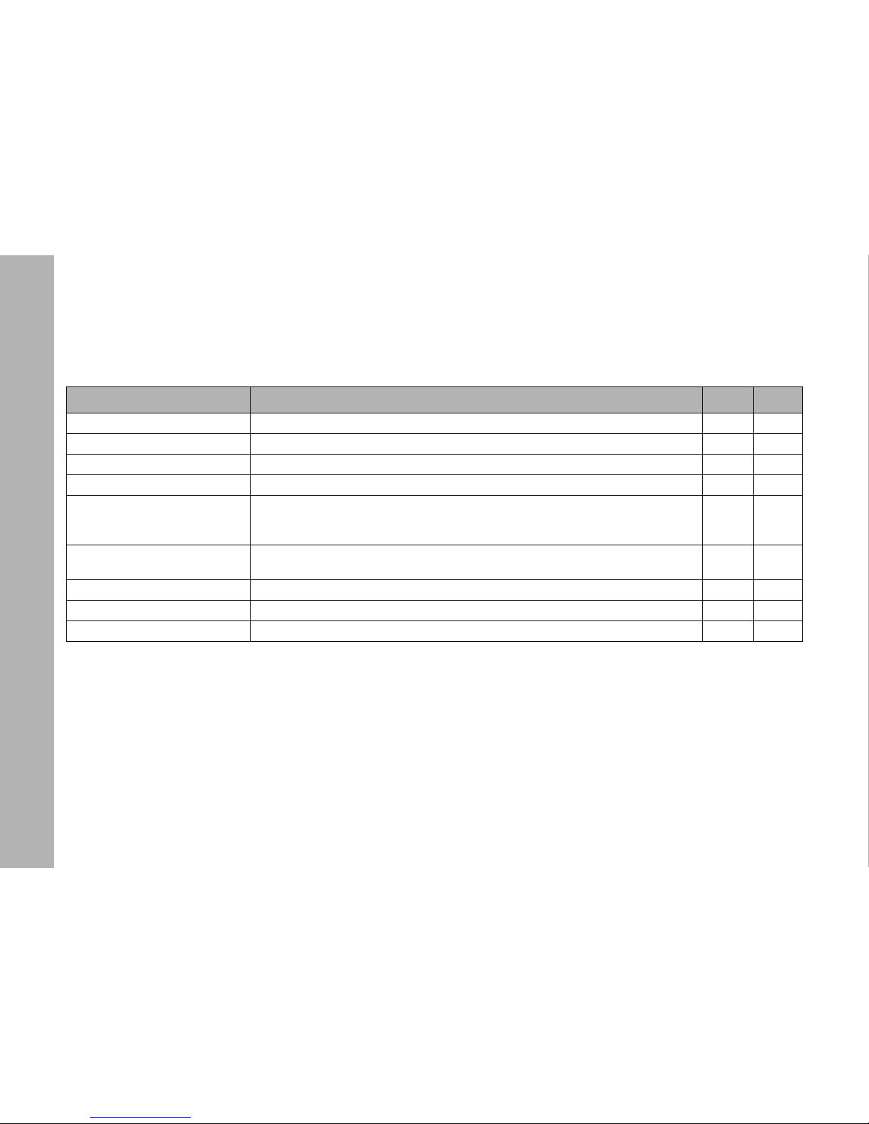
RDM commands
30
RDM commands
From Firmware-version 2.0
Command Description GET SET
Discover Unique Branch Searches RDM device X X
Discover Mute Mutes the RDM device, no response messages X X
Discover Unmute Activates device for response messages X X
Supported Parameters Shows a list of all supported RDM commands X
Parameter Description
Shows a list of commands that are not standard rdm commands, mostly commands
from manufacturer. Describes the data type and shows if Set or Get or both are supported for the listed commands.
X
Device Info
Lists RDM protocol version, device model ID, product category, software version ID
(from Main), DMX footprint, DMX personality, sub-device count and sender count.
X
Software Version Label Shows the software version string from main, e.g. Main 1.66.1 Yes 16 2012 19:10:26 X
DMX Start Address DMX address XX
Identify Service Identify Flag -> physically fl ash the light, ARRI L5-C flashes Blue and all other White X X
Page 31
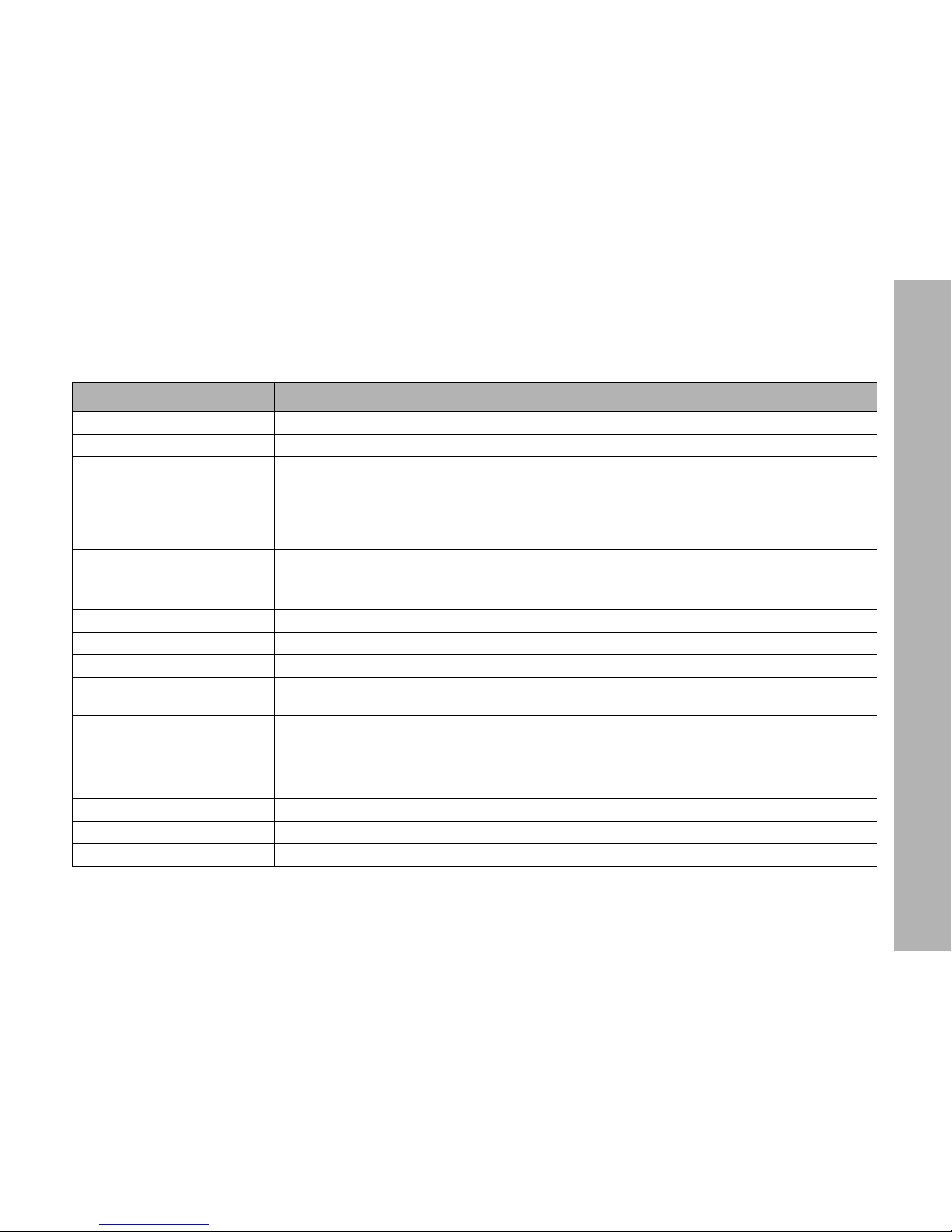
RDM commands
31
Required RDM command extensions
Command Description GET SET
Status Message Display of actual warning / error message of the fixture. X
Status ID Description Detailed description of each warning / status report. X
Device Label
This parameter allows you to generate an informative label for each fixture. It can be
utilized to identify the rack number of a dimmer or to determine the position of a fixture
XX
Product Detail ID List
This parameter is utilized to retrieve technical details of a fixture. ARRI L5 shows
LED with PWM control
X
Device Model Description
A text description of up to 32 characters for the model type of the fixture. ARRI L5-C,
ARRI L5 Daylight Tuneable or ARRI L5 Tungsten Tuneable
X
Manufacturer Label Display the company name ARRI Lighting X
Boot Software Version ID PrBo SW Version e.g. „2.03.00“ X
Boot Software Version Label Shows text from PrBo Bootloader, e.g. PrBo 2.03.00 Jan 16 2012 19:10:26 X
DMX Personality DMX mode XX
DMX Personality Description
Displays a text description of a DMX mode with up to 32 characters, shown exactly
as in the description in the LS-Manager
X
Slot Info Shows a description for each DMX channel in use in the requested DMX mode X
Slot Description
Shows a text description with max. 32 characters for each DMX channel from the
requested DMX mode
X
Default Slot Value Shows the default DMX channel value from the requested DMX mode X
Sensor Definition Shows the definition from a specific sensor and a text description X
Sensor Value Shows the actual sensor value X
Device Hours Shows the actual device hours of the fixture X
Page 32
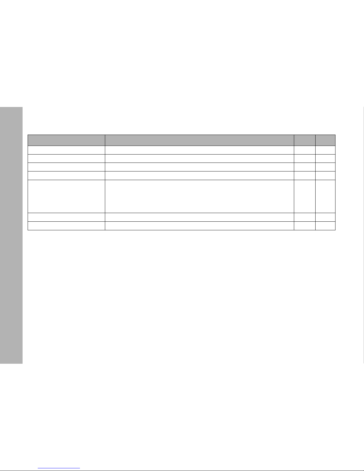
RDM commands
32
Lamp Hours Shows the actual lamp hours of the fixture X
Factory Defaults This command deletes all user parameters and sets the fixture to factory default X X
Device Power Cycles Shows the power cycle value, counts every cold start (switch or power-up) X
Reset Device Fixture makes a software reset (warm start) and carries out a reboot X X
Power State
Power state of the fixture, supported power states:
POWER_STATE_STANDBY (0x02),
POWER_STATE_NORMAL (0xFF),
POWER_STATE_FULL_OFF (0x00)
POWER_STATE_SHUTDOWN (0x01)
XX
Perform Selftest Supported test modes and demo modes X X
Self Test Description Shows a description for each test / demo mode X
Command Description GET SET
Page 33
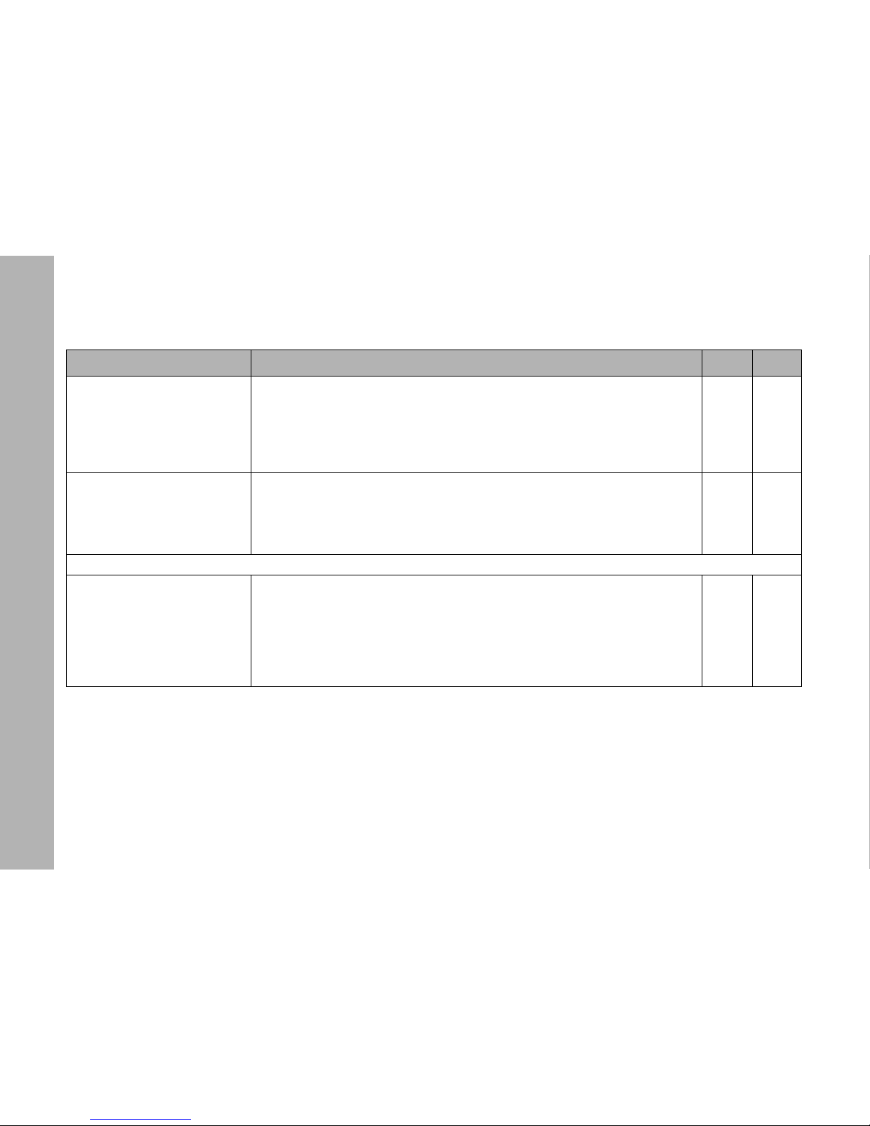
L-Series Manager
33
Manufacturer commands
L-Series Manager
Please find information about the features and the functionality of the L-Series manager in the user manual for the L-Series manager, which can be downloaded with the L-Series manager software-bundle from the ARRI web site www.arri.com free of charge.
Command Description GET SET
RDM Fan Mode
PID: 0x8001
Changes the FAN mode of the fixture
- this message supports Set and Get commands
- the first data byte is used to show / change the fan mode
USER_FAN_MODE_LOW = 1
USER_FAN_MODE_VARI = 2
USER_FAN_MODE_HI45 = 3
XX
RDM Status LED
PID: 0x8002
Switch on /off indication LEDs and LCD back light
- this message supports Set and Get commands
- the first data byte is used to switch indication LEDs on and off
LEDs and LCD back light on = 0
LEDs and LCD back light off = 1
XX
Supported values from -1 to +1
RDM DMX Signal Lost Mode
PIS: 0x8005
If the DMX signal gets lost or the DMX device is unplugged the LED fixture holds the
last valid signal, or it holds the last valid signal for two minutes and then douses or
switches off immediately.
Supported values:
0 -> hold
1 -> hold 2 minutes
3 -> switch off
XX
Page 34
Error messages
34
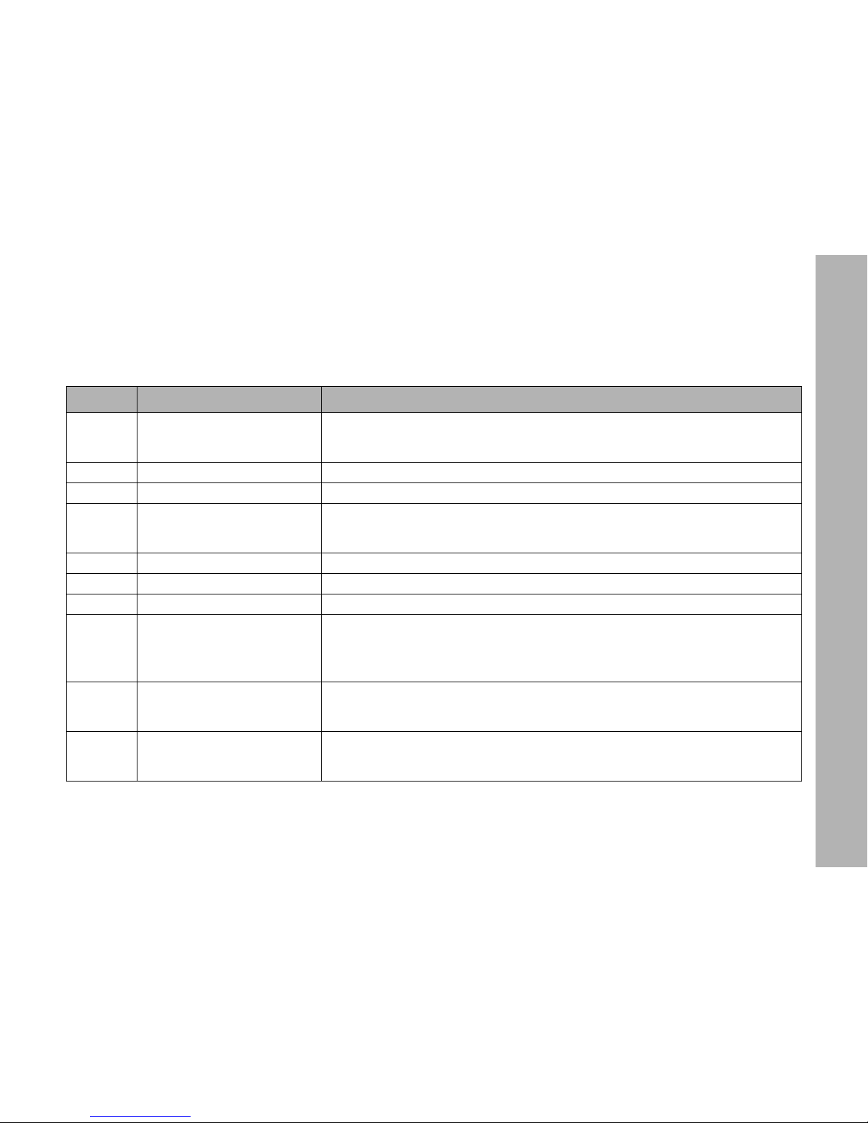
Error messages
From firmware-version 2.0
Code Error Remedy
E.003
Controller over temperature.
STATUS lit up red.
Let the product cool down. The STATUS indicator changes to green when the product
reaches the safe temperature operating zone again. Turn the dimmer knob to „0“ or send
an intensity value „0“ via DMX to activate the light engine again.
E.004 Light engine over temperature See E.003
E.005 Power supply over temperature See E.003
E.006
Calibration data of light engine
faulty or EEPROM error.
WARNING: Loss of calibration data. This error can only be fixed by re-calibrating the light
engine.
Please contact the ARRI service.
E.007 Invalid PWM value calculation Notice: The product can be used on. This message is more a notification than an error.
E.008 Invalid values during calculation See E.007
E.009 Invalid values during calculation See E.007
E.010
Fan error. The detected fan
speed deviates from the programmed fan speed or the fan
doesn’t run at all.
CAUTION: Only a trained service person is allowed to fix this error!
Set the fan to LOW or HI and see if it starts rotating, in order to determine if there is an
electrical malfunction.
All mechanical tests or repairs may only be carried out by a trained service technician.
E.011
Fixture menu module not be
detected.
If the fixture menu is working, error E.011 can be ignored. However, if the fixture menu
remains dark (no LED lights up) we recommend to contact the ARRI service. They can
then carry out detailed analyses.
E.012
Temperature sensor(s) are
defective or deviation within
NTC values too high.
One or more temperature sensors are defective or the deviation within the individual NTCs
or BNTCs exceeds the variation tolerance of 12° C / 54° F. Check the error log (LSeries
Manager) to see which temperature sensors are affected. Contact the ARRI service.
Page 35
Error messages
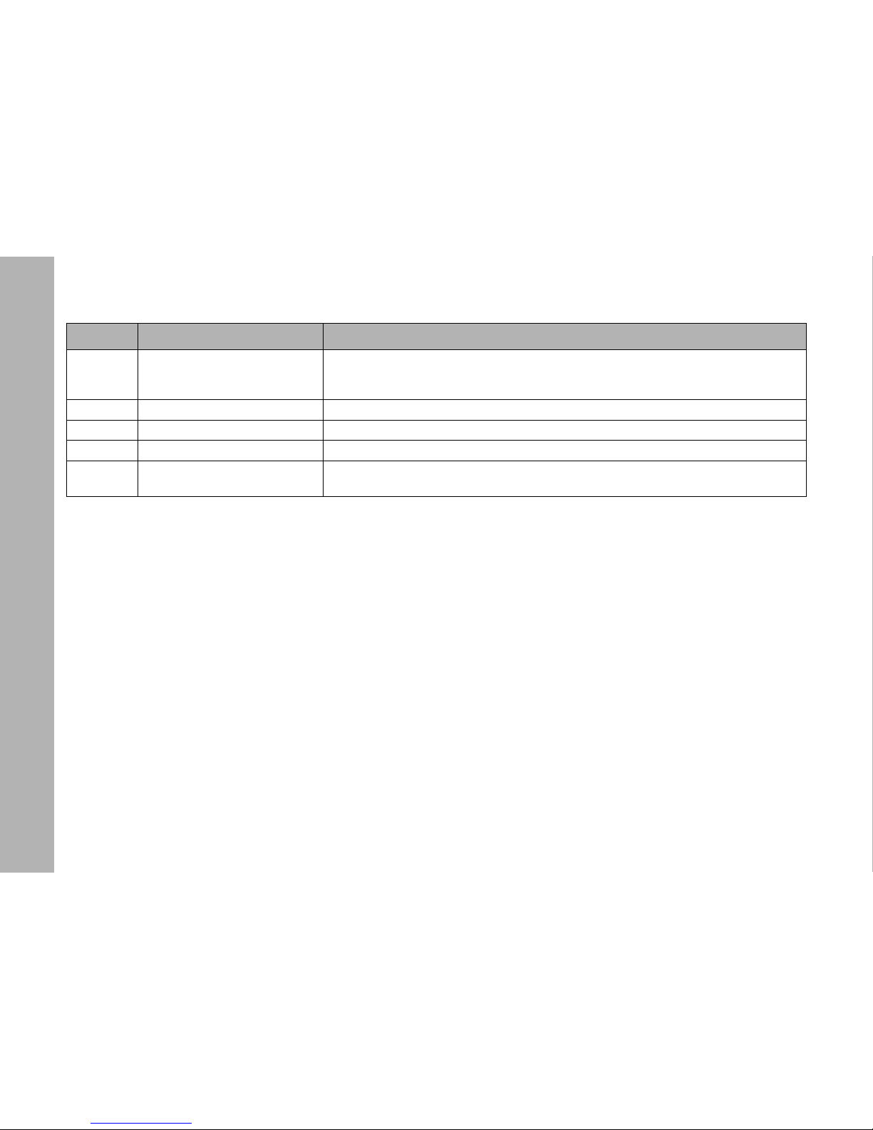
35
E.013
Calibration data of controller
faulty or EEPROM error.
WARNING: Loss of calibration data. This error can only be fixed by re-calibrating the controller.
Please contact the ARRI service.
E.014 Watchdog error Notice: The product can be used on. This message is more a notification than an error.
E.015 LED channel faulty Notice: The product can be used on. This message is more a notification than an error.
E.016 Battery voltage protection active The battery input detected an input voltage higher than 44 V=.
E.017 Low battery shut off
The output voltage of the battery pack is lower than 23 V=. Change the battery pack. The
product will not react to commands until you disconnect it from the power source.
Code Error Remedy
Page 36
DMX protocol
36
DMX protocol
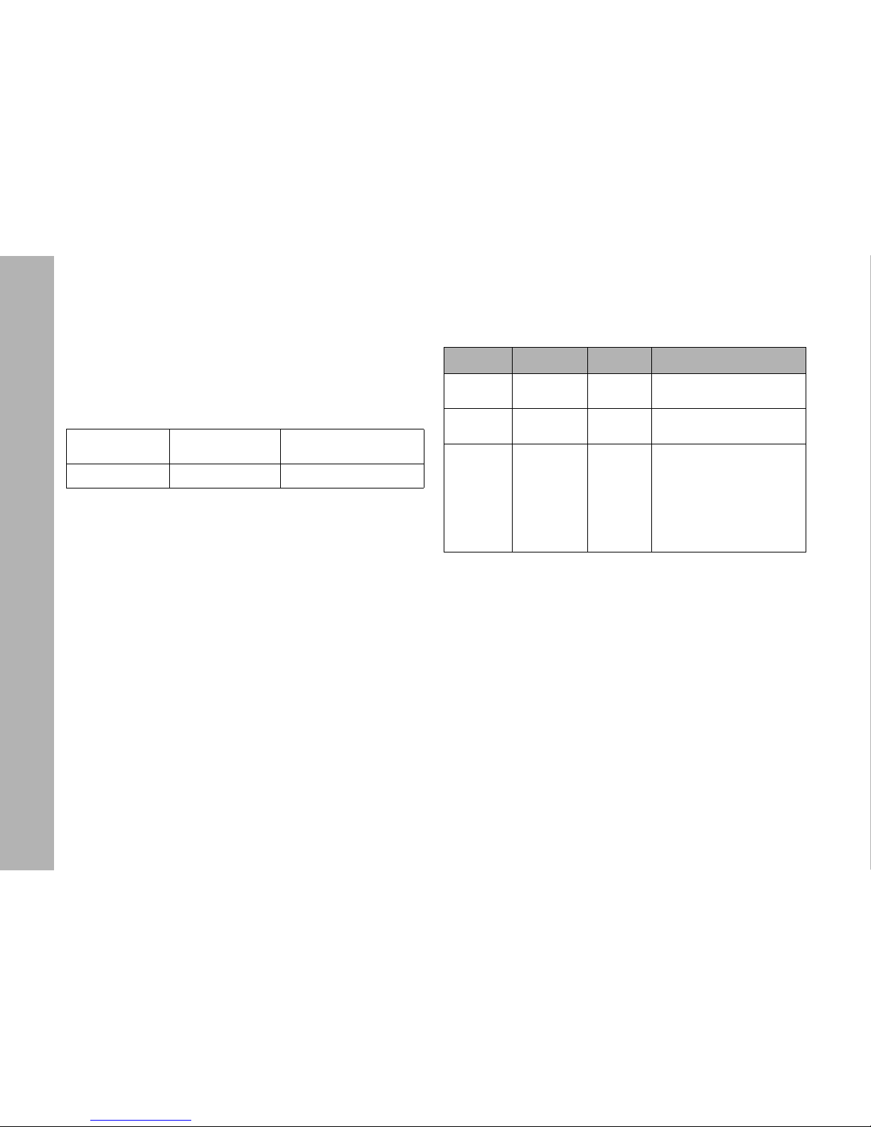
ARRI L5-TT (Tungsten Tuneable)
From firmware-version 2.0
Overview
*
= Factory default
GN saturation
The value describes the shift from the neutral point to full minus
green or full plus green in percent.
(Reference: Rosco Cinegel #3304 and #3308)
Mode 1: 8 bit resolution per function
8 bit, 1 channel
per function
16 bit, 2 cannels
per function
Coarse / fine, 1-2
channels per function
DMX mode 1
*
DMX mode 2 DMX mode 3
Channel Value Percent Function
1
0-255 0-100
Dimmer
closed → open
2
0-255 0-100
Color temperature CCT
2.600 K → 3.600 K
3
0-10
11- 20
21-119
120-145
146-244
245-255
0-4
5-8
8-46
47-57
57-96
96-100
GN saturation
neutral / no effect
full minus green
-99% → -1%
neutral / no effect
1% → 99%
full plus green
Page 37
DMX protocol
37
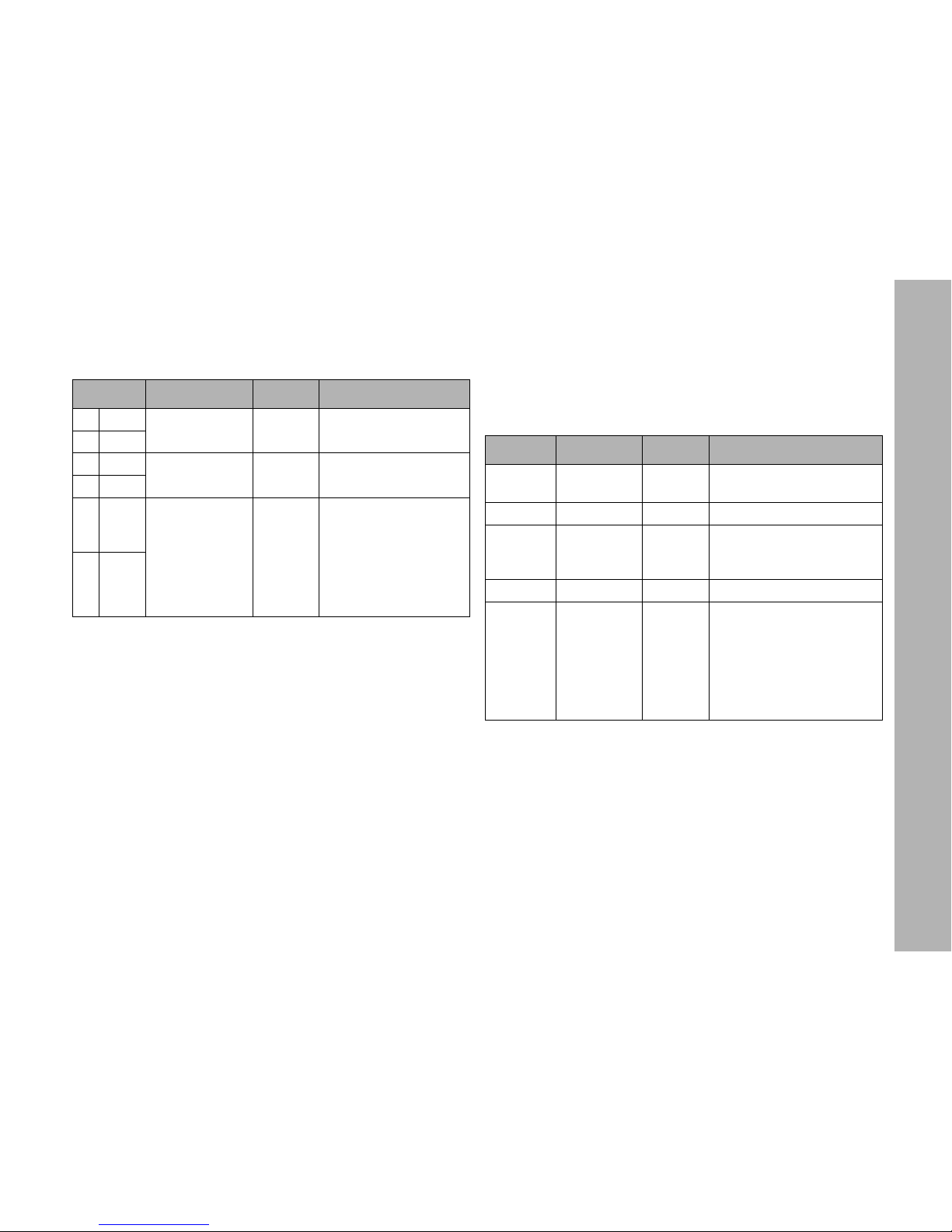
Mode 2: 16 bit resolution per function Mode 3: Coarse / fine channel per function
Each of the 256 coarse steps is divided in 256 fine steps. Use
this mode when your lighting control desk does not support true
16 bit resolution.
Channel Va lue Percent Function
1HI
0-65535 0-100
Dimmer
closed → open
2LO
3HI
0-65535 0-100
Color temperature
2.600 K → 3.600 K
4LO
5HI 0-5.000
5.001-10.000
10.001-29.999
30.000-40.000
40.001-59.999
60.000-65.535
0-7
8-15
16-46
46-61
61-92
92-100
GN saturation
neutral / no effect
full minus green
-99% → -1%
neutral / no effect
1% → 99%
full plus green
6LO
Channel Value Percent Function
1
0-255 0-100
Dimmer coarse
closed → open
2 0-255 0-100 Dimmer fine
3
0-255 0-100
Color temperature
coarse
2.600 K → 3.600 K
4 0-255 0-100 Color temperature fine
5
0-10
11- 20
21-119
120-145
146-244
245-255
0-4
5-8
8-46
47-57
57-96
96-100
GN saturation
neutral / no effect
full minus green
-99% → -1%
neutral / no effect
1% → 99%
full plus green
Page 38
DMX protocol
38
ARRI L5-DT (Daylight Tuneable)
From firmware-version 2.0
Overview
*
= Factory default
GN saturation
The value describes the shift from the neutral point to full minus
green or full plus green in percent.
(Reference: Rosco Cinegel #3304 and #3308)
Mode 1: 8 bit resolution per function
8 bit, 1 channel
per function
16 bit, 2 channels
per function
Coarse / fine, 2 channels per function
DMX mode 1
*
DMX mode 2 DMX mode 3
Channel Valu e Percent Function
1
0-255 0-100
Dimmer
closed → open
2
0-255 0-100
Color temperature CCT
5.000 K → 6.500 K
3
0-10
11- 20
21-119
120-145
146-244
245-255
0-4
5-8
8-46
47-57
57-96
96-100
GN saturation
neutral / no effect
full minus green
-99% → -1%
neutral / no effect
1% → 99%
full plus green
Page 39
DMX protocol
39
Mode 2: 16 bit resolution per function Mode 3: Coarse / fine channel per function
Each of the 256 coarse steps is divided in 256 fine steps. Use
this mode when your lighting control desk does not support true
16 bit resolution.
Channel Val ue Percent Function
1HI
0-65535 0-100
Dimmer
closed → open
2LO
3HI
0-65535 0-100
Color temperature
CCT
5.000 K → 6.500 K
4LO
5 HI 0-5.000
5.001-10.000
10.001-29.999
30.000-40.000
40.001-59.999
60.000-65.535
0-7
8-15
16-46
46-61
61-92
92-100
GN saturation
neutral / no effect
full minus green
-99% → -1%
neutral / no effect
1% → 99%
full plus green
6LO
Channel Va lue Percent Function
1
0-255 0-100
Dimmer coarse
closed → open
2 0-255 0-100 Dimmer fine
3
0-255 0-100
Color temperature coarse
5.000 K → 6.500 K
4 0-255 0-100 Color temperature fine
5
0-10
11- 20
21-119
120-145
146-244
245-255
0-4
5-8
8-46
47-57
57-96
96-100
GN saturation
neutral / no effect
full minus green
-99% → -1%
neutral / no effect
1% → 99%
full plus green
Page 40
DMX protocol
40
ARRI L5-C
From firmware-version 2.0
Overview
*
= Factory default
GN saturation
The value describes the shift from the neutral point to full minus
green or full plus green in percent.
(Reference: Rosco Cinegel #3304 and #3308)
Mode 1: White & RGBW, 8 bit resolution per function
8 bit, 1 channel
per function
16 bit, 2 cannels
per function
Coarse/fine, 1-2 channels per function
DMX mode 1
*
White & RGBW
DMX mode 6
White & RGBW
DMX mode 11
White & RGBW
DMX mode 2
White
DMX mode 7
White
DMX mode 12
White
DMX mode 3
White & HSI
DMX mode 8
White & HSI
DMX mode 13
White & HSI
DMX mode 4
RGBW
DMX mode 9
RGBW
DMX mode 14
RGBW
DMX mode 5
HSI
DMX mode 10
HSI
DMX mode 15
HSI
Channel Value Percent Function
1
0-255 0-100
Dimmer
closed → open
2
0-255 0-100
Color temperature CCT
2.800 K → 10.000 K
3
0-10
11- 20
21-119
120-145
146-244
245-255
0-4
5-8
8-46
47-57
57-96
96-100
GN saturation
neutral / no effect
full minus green
-99% → -1%
neutral / no effect
1% → 99%
full plus green
4
0-255 0-100
Xfade to color
White → RGBW color
5
0-255 0-100
Intensity red
0% → 100%
6
0-255 0-100
Intensity green
0% → 100%
7
0-255 0-100
Intensity blue
0% → 100%
8
0-255 0-100
Intensity white
0% → 100%
Page 41
DMX protocol
41
Mode 2: White, 8 bit resolution per function Mode 3: White & HSI, 8 bit resolution per function
Channel Value Percent Function
1
0-255 0-100
Dimmer
closed → open
2
0-255 0-100
Color temperature CCT
2.800 K → 10.000 K
3
0-10
11- 20
21-119
120-145
146-244
245-255
0-4
5-8
8-46
47-57
57-96
96-100
GN saturation
neutral / no effect
full minus green
-99% → -1%
neutral / no effect
1% → 99%
full plus green
Channel Value Percent Function
1
0-255 0-100
Dimmer
closed → open
2
0-255 0-100
Color temperature CCT
2.800 K → 10.000 K
3
0-10
11- 20
21-119
120-145
146-244
245-255
0-4
5-8
8-46
47-57
57-96
96-100
GN saturation
neutral / no effect
full minus green
-99% → -1%
neutral / no effect
1% → 99%
full plus green
4
0-255 0-100
Xfade to color
White → RGBW color
5
0-255 0-100
Hue
0° → 360°
6
0-255 0-100
Saturation
0 → full saturated
Page 42
DMX protocol
42
Mode 4: RGBW, 8 bit resolution per function
Mode 5: HSI, 8 bit resolution per function
Mode 6: White & RGBW, 16 bit resolution per function
Channel Value Percent Function
1
0-255 0-100
Dimmer
closed → open
2
0-255 0-100
Intensity red
0% → 100%
3
0-255 0-100
Intensity green
0% → 100%
4
0-255 0-100
Intensity blue
0% → 100%
5
0-255 0-100
Intensity white
0% → 100%
Channel Value Percent Function
1
0-255 0-100
Dimmer
closed → open
2
0-255 0-100
Hue
0° → 360°
3
0-255 0-100
Saturation
0 → full saturated
Channel Va lue Percent Function
1HI
0-65535 0-100
Dimmer
closed → open
2LO
5HI 0-5.000
5.001-10.000
10.001-29.999
30.000-40.000
40.001-59.999
60.000-65.535
0-7
8-15
16-46
46-61
61-92
92-100
GN saturation
neutral / no effect
full minus green
-99% → -1%
neutral / no effect
1% → 99%
full plus green
6LO
7HI
0-65.535 0-100
Xfade to color
White → RGBW color
8LO
9HI
0-65.535 0-100
Intensity red
0% → 100%
10 LO
11 HI
0-65.535 0-100
Intensity green
0% → 100%
12 LO
13 HI
0-65.535 0-100
Intensity blue
0% → 100%
14 LO
15 HI
0-65.535 0-100
Intensity white
0% → 100%
16 LO
Page 43
DMX protocol
43
Mode 7: White, 16 bit resolution per function Mode 8: White & HSI, 16 bit resolution per function
Channel Value Percent Function
1HI
0-65535 0-100
Dimmer
closed → open
2LO
7HI
0-65.535 0-100
Color temperature
2.800 K → 10.000 K
8LO
5 HI 0-5.000
5.001-10.000
10.001-29.999
30.000-40.000
40.001-59.999
60.000-65.535
0-7
8-15
16-46
46-61
61-92
92-100
GN saturation
neutral / no effect
full minus green
-99% → -1%
neutral / no effect
1% → 99%
full plus green
6LO
Channel Va lue Percent Function
1HI
0-65535 0-100
Dimmer
closed → open
2LO
7HI
0-65.535 0-100
Color temperature
2.800 K → 10.000 K
8LO
5HI 0-5.000
5.001-10.000
10.001-29.999
30.000-40.000
40.001-59.999
60.000-65.535
0-7
8-15
16-46
46-61
61-92
92-100
GN saturation
neutral / no effect
full minus green
-99% → -1%
neutral / no effect
1% → 99%
full plus green
6LO
7HI
0-65.535 0-100
Xfade to color
White → RGBW color
8LO
9HI
0-65.535 0-100
Hue
0° → 360°
10 LO
11 HI
0-65.535 0-100
Saturation
0 → full saturated
12 LO
Page 44
DMX protocol
44
Mode 9: RGBW, 16 bit resolution per function Mode 10: HSI, 16 bit resolution per function
Channel Value Percent Function
1HI
0-65535 0-100
Dimmer
closed → open
2LO
3HI
0-65.535 0-100
Intensity red
0% → 100%
4LO
5HI
0-65.535 0-100
Intensity green
0% → 100%
6LO
7HI
0-65.535 0-100
Intensity blue
0% → 100%
8LO
9HI
0-65.535 0-100
Intensity white
0% → 100%
10 LO
Channel Valu e Percent Function
1HI
0-65535 0-100
Dimmer
closed → open
2LO
3HI
0-65.535 0-100
Hue
0° → 360°
4LO
5HI
0-65.535 0-100
Saturation
0 → full saturated
6LO
Page 45
DMX protocol
45
Mode 11: White & RGBW, Coarse/fine per function
Mode 12: White, Coarse / fine channel per function
Channel Value Percent Function
1
0-255 0-100
Dimmer coarse
closed → open
2 0-255 0-100 Dimmer fine
3
0-255 0-100
Color temperature
coarse
2.800 K → 10.000 K
4 0-255 0-100 Color temperature fine
5
0-10
11- 20
21-119
120-145
146-244
245-255
0-4
5-8
8-46
47-57
57-96
96-100
GN saturation
neutral / no effect
full minus green
-99% → -1%
neutral / no effect
1% → 99%
full plus green
6
0-255 0-100
Xfade to color
White → RGBW color
7
0-255 0-100
Intensity red coarse
0% → 100%
8 0-255 0-100 Red fine
9
0-255 0-100
Intensity green coarse
0% → 100%
10 0-255 0-100 Green fine
11
0-255 0-100
Intensity blue coarse
0% → 100%
12 0-255 0-100 Blue fine
13
0-255 0-100
Intensity white coarse
0% → 100%
14 0-255 0-100 White fine
Channel Value Percent Function
1
0-255 0-100
Dimmer coarse
closed → open
2 0-255 0-100 Dimmer fine
3
0-255 0-100
Color temperature
coarse
2.800 K → 10.000 K
4 0-255 0-100 Color temperature fine
5
0-10
11- 20
21-119
120-145
146-244
245-255
0-4
5-8
8-46
47-57
57-96
96-100
GN saturation
neutral / no effect
full minus green
-99% → -1%
neutral / no effect
1% → 99%
full plus green
Channel Valu e Percent Function
Page 46
DMX protocol
46
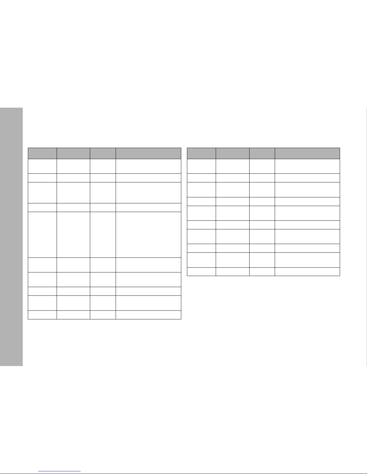
Mode 13: White & HSI, Coarse / fine channel per function Mode 14: RGBW, Coarse / fine channel per function
Channel Value Percent Function
1
0-255 0-100
Dimmer coarse
closed → open
2 0-255 0-100 Dimmer fine
3
0-255 0-100
Color temperature
coarse
2.800 K → 10.000 K
4 0-255 0-100 Color temperature fine
5
0-10
11- 20
21-119
120-145
146-244
245-255
0-4
5-8
8-46
47-57
57-96
96-100
GN saturation
neutral / no effect
full minus green
-99% → -1%
neutral / no effect
1% → 99%
full plus green
6
0-255 0-100
Xfade to color
White → RGBW color
7
0-255 0-100
Hue coarse
0 → 360°
8 0-255 0-100 Hue fine
9
0-255 0-100
Saturation coarse
0 → full saturated
10 0-255 0-100 Saturation fine
Channel Valu e Percent Function
1
0-255 0-100
Dimmer coarse
closed → open
2 0-255 0-100 Dimmer fine
3
0-255 0-100
Intensity red coarse
0% → 100%
4 0-255 0-100 Red fine
5
0-255 0-100
Intensity green coarse
0% → 100%
6 0-255 0-100 Green fine
7
0-255 0-100
Intensity blue coarse
0% → 100%
8 0-255 0-100 Blue fine
9
0-255 0-100
Intensity white coarse
0% → 100%
10 0-255 0-100 White fine
Page 47
DMX protocol
47
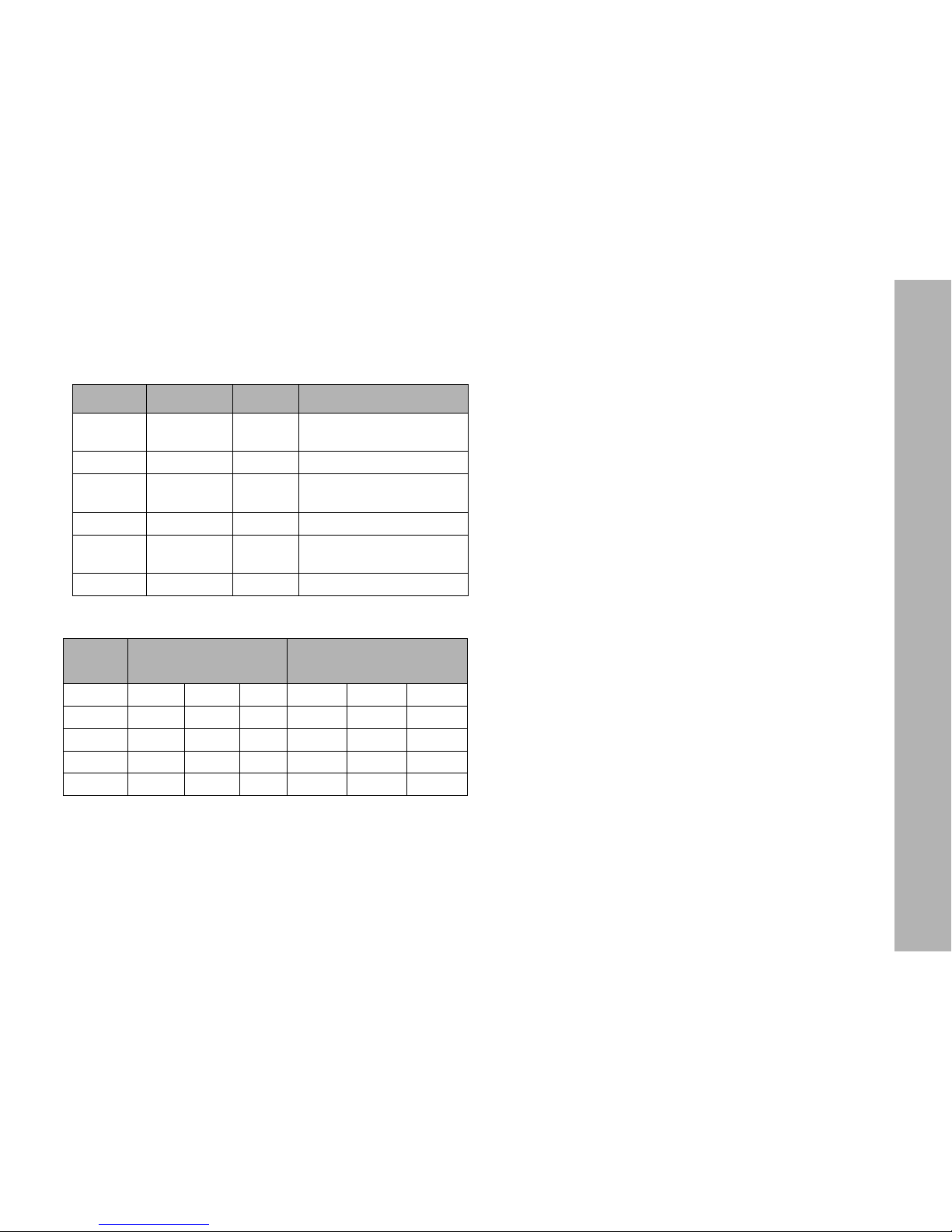
Mode 15: HSI, Coarse / fine channel per function
Overview of typical CCT values as DMX values
To calculate CCT values in DMX % and vice versa
Use the following formulas to transform CCT values in DMX %
values and vice versa:
CCT values for the ARRI L5 models:
L5-TT (Tungsten Tuneable)
CCT
min
= 2.600 K
CCT
max
= 3.600 K
L5-DT (Daylight Tuneable)
CCT
min
= 5.000 K
CCT
max
= 6.500 K
L5-C
CCT
min
= 2.800 K
CCT
max
= 10.000 K
Channel Value Percent Function
1
0-255 0-100
Dimmer coarse
closed → open
2 0-255 0-100 Dimmer fine
3
0-255 0-100
Hue coarse
0 → 360°
4 0-255 0-100 Hue fine
5
0-255 0-100
Saturation coarse
0 → full saturated
6 0-255 0-100 Saturation fine
CCTValue
DMX-Value (8 bit) DMX-Value (16 bit)
L5-TT L5-DT L5-C L5-TT L5-DT L5-C
3.200 K 153 -- 14 39.321 -- 3.670
5.600 K -- 102 99 -- 26.214 25.493
6.000 K -- 170 113 -- 43.712 29.098
6.500 K -- 100% 131 -- 65.535 33.685
CCT
Target
CCT
max
CCT
min
–()DMX
in percent
×
100
-----------------------------------------------------------------------------------------
CCT
min
×=
DMX
in percent
CCT
recent
CCT
min
–
CCT
max
CCT
min
–
-------------------------------------------------
100×=
Page 48

Specifications
48
Specifications
Physical
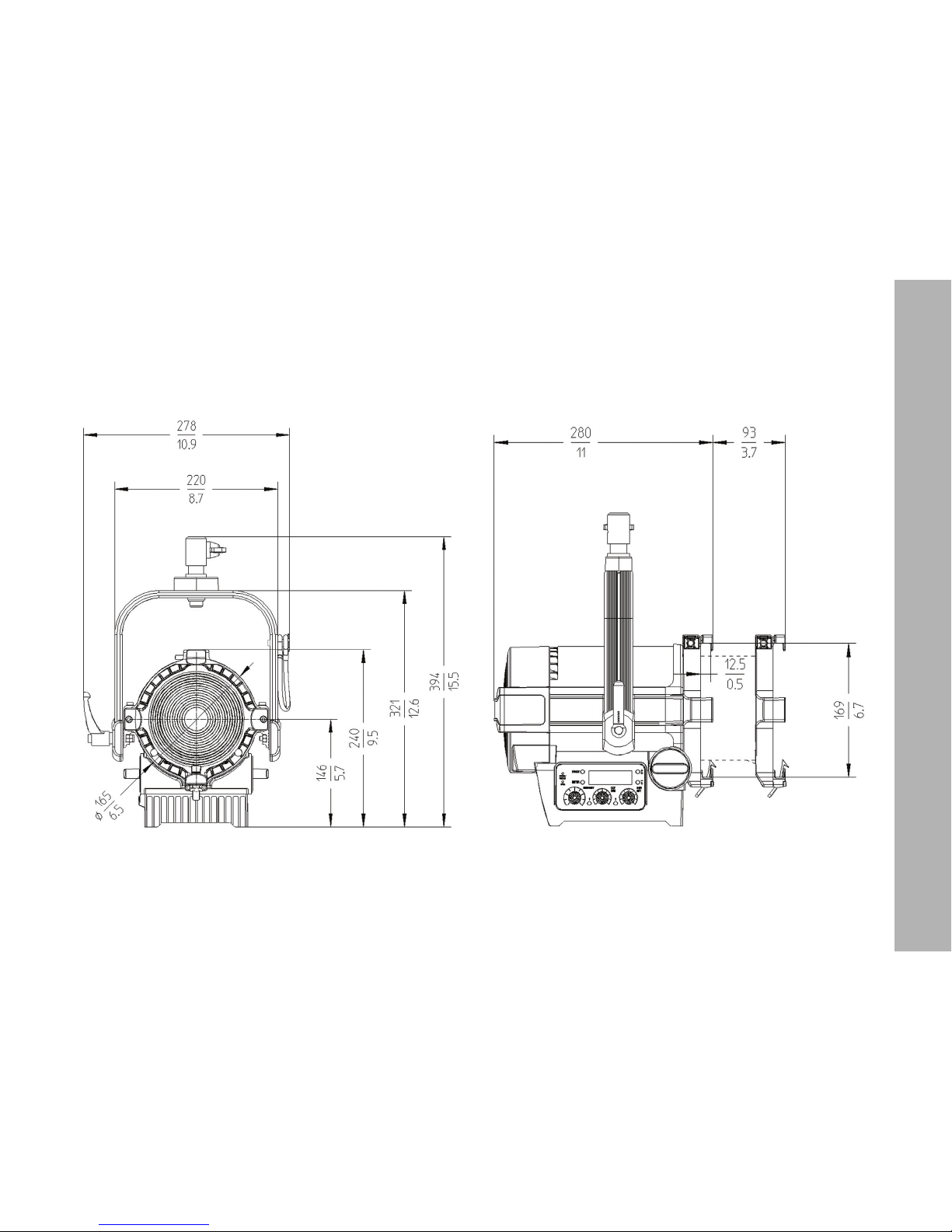
Length (Focus in flood position) . . . . . . . . . . . . . . . 280 mm (11 in.)
Length (Focus in spot position) . . . . . . . . . . . . . 373 mm (14.7 in.)
Width . . . . . . . . . . . . . . . . . . . . . . . . . . . . . . . . . . 220 mm (8.7 in.)
Height . . . . . . . . . . . . . . . . . . 240 mm (9.5 in., Stirrup folded down)
Latch distance . . . . . . . . . . . . . . . . . . . . . . . . . . . . 169 mm / 6.65 “
Width for accessories . . . . . . . . . . . . . . . . . . . . . . . . 168 mm / 6.6 “
Weight (manual version, w/o accessories) . . . . . . 5.1 kg (11.2 lbs.)
Weight (P.O. version, w/o accessories) . . . . . . . . 7.0 kg (15.4 lbs.)
Light source
Type . . . . . . . . . . . . . . . . . . . . . . . . . . . . . . ARRI LED Lightengine
Typ. LED lifetime L70 . . . . . . . . . . . . . . . . . . . . . . . . . . . . 50.000 h
White light. . . . . . . . . . . . . . . . . . . 2.800 K - 10.000 K (ARRI L5-C)
. . . . . . . . . . . . . . . . . . . . . . . . . . . 2.600 K - 3.600 K (ARRI L5-TT)
. . . . . . . . . . . . . . . . . . . . . . . . . . . 5.000 K - 6.500 K (ARRI L5-DT)
Colored light . . . . . . . . . . . . .RGBW color mixing (only ARRI L5-C)
Color rendering index . . . . . . . . . . . . . . . . . . . . . . . . . typ. CRI >94
Green/Magenta saturation . . . . . . +/- 1 (full green to full magenta)
Optical path
Type . . . . . . . . . . . . . . . . . . . . . . . . . . . . . . . . . Fresnel, focussable
Lens diameter. . . . . . . . . . . . . . . . . . . . . . . . . . . . . . . . 137 mm / 5“
Half peak angle. . . . . . . . . . . . . . . . . . . . . . . . . . . . . . . . . 15° - 50°
Dynamic functions
Dimmer . . . . . . . . . . . . . . . . . . . . . . . . . . . . . . .electronic, 0 - 100%
Color mixing . . . . . . . . . . . . . . . . . . . . . . . . . . . RGBW color mixing
. . . . . . . . . . . . . . . . . . . . . . . .(Hue and saturation, only ARRI L5-C)
Control and Programming
DMX channels . . . . . 1-16 channels, depending on type and mode
Setting and addressing. . . . . . . . . . . . . . . . Fixture menu and RDM
DMX compliance . . . . . . . . . . . . . . . . . . . . . . . . .ESTA DMX 512A
RDM compliance . . . . . . . . . . . . . . . . . . . . . . . . .ESTA DMX 512A
Firmware update. . . . . . . . . . . . . . .USB interface and LS manager
Construction
Color . . . . . . . . . . . . . . . . . . . . . . . . . . . . . . . . . Blue/silver or black
Housing . . . . . . . . . . . . . Composite housing with aluminum frame
Protection rating . . . . . . . . . . . . . . . . . . . . . . . . . . . . . . . . . . . IP 20
Installation
Mounting. . short 28 mm (1.1 in.) spigot with 16 mm (0.63 in.) hole
Orientation . . . . . . . . . . . . . . . . . . . . . . . . . . . . . . . . . . . . . . +/- 90°
Minimum clearance around fixture . . . . . . . . . . . . . 0,5 m (19.7 in.)
Minimum view distance to light aperture . . . . . . . . 0,5 m (19.7 in.)
Connections
AC power input . . . . . . . . . . . . . . . . . Neutrik® PowerCON® True1
Battery power input. . . . . . . . . . . . . . . 4-pin locking XLR connector
DMX and RDM data in/out . . . . . . . . 5-pin, locking XLR connector
USB connector . . . . . . . . . . . . . . . . . . . . . . . . . . . . . . . Mini-USB-A
Page 49

Specifications
49
Electrical
AC power . . . . . . . . . . . . . . . . . . . . . . . 90 - 250 V~, 45 - 65 Hz AC
Power supply . . . . . . . Auto-sensing switching-mode power supply
Fuse . . . . . . . . . . . . . . . . . . . . . . . . . . . . 2 A T, 250 V~, 5 x 20 mm
Battery voltage . . . . . . . . . . . . . . . . . . . . . . . . . . . . . . . .23 - 36 V =
Typical Power
230 V, 50 Hz. . . . . . . . . . . . . . . . . . . . . . . . . . . . . . . . . . . . . 115 W
cos
ϕ. . . . . . . . . . . . . . . . . . . . . . . . . . . . . . . . . . . . . . . . . . . . > 0.9
Measurements made at nominal voltage with all LEDs at full intensity.
Allow for a deviation of +/- 10%
Noise emission
Ambient temperature = 35° C (95° F). . . . . . . . . . . . . . . < 20dB(A)
Ambient temperature = 45° C (113° F). . . . . . . . . . . . . . < 30dB(A)
Thermal
Minimum ambient temperature (ta). . . . . . . . . . . . . . .-20° C (-4° F)
Maximum ambient temperature (t
a
) . . . . . . . . . . . . . 45° C (113° F)
Cooling . . . . . . . . . . . . . .Silent, temperature-controlled fan cooling
Approvals
EU safety . . . . . . . . . . . . . . . . . . . . . . . . . . . . EN / IEC 60598-2-17
EN / IEC 60598-1
EN / IEC 62471
EN / IEC 62493
EU EMC . . . . . . . . . . . . . . . . . . . . . . . . . . . . . . . . . . . . . EN 55015
EN / IEC 61000-3-2
EN / IEC 61000-3-3
EN / IEC 61547
CISPR 15
US safety . . . . . . . . . . . . . . . . . . . . . . . . . . . . . . . . . . . . . . UL1573
US EMC . . . . . . . . . . . . . . . . . . . . . . . . . . . . . . FCC CFR 47 Part 2
FCC CFR 47 Part 15
Canada safety . . . . . . . . . . . . . . . . . . . . CAN/CSA C22.2 No. 166
CAN/CSA C22.2 No. 9.0
CAN/CSA C22.2 N0. 9.0S1
Canada EMC . . . . . . . . . . . . . . . . . . . . . . . . . . . . . . . . . . ICES-003
Included items
Short 28 mm spigot with 16 mm hole,
and short fixing screw (set). . . . . . . . . . . . . . . . . . . . . . L2.40701.2
Short instructions . . . . . . . . . . . . . . . . . . . . . . . . . . . . . L5.0001304
Power input cable
Accessories
Power input cable 1,5 m, EN, PowerCon TRUE1, bare end . . . . .
. . . . . . . . . . . . . . . . . . . . . . . . . . . . . . . . . . . . . . . . . . . L2.0001485
Power input cable 3,0 m, EN, Switch, PowerCon TRUE1,
Schuko plug . . . . . . . . . . . . . . . . . . . . . . . . . . . . . . . . L2.0001486
Power input cable 7,0 m, US, Switch, PowerCON TRUE1,
Edison plug . . . . . . . . . . . . . . . . . . . . . . . . . . . . . . . . . L2.0001487
4-leaf barndoor (168 mm, 6.6 “) . . . . . . . . . . . . . . . . . . L2.79470.0
8-leaf barndoor (168 mm, 6.6 “) . . . . . . . . . . . . . . . . . . L2.79500.0
Filter frame (168 mm, 6.6 “) . . . . . . . . . . . . . . . . . . . . . L2.79490.0
Scrim (168 mm, 6.6 “). . . . . . . . . . . . . . . . . . . . . . . . . . L2.79460._
Page 50

Specifications
50
Order information
L5-C, P.O., black, bare end . . . . . . . . . . . . . . . . . . . . . L0.0001952
L5-C, P.O., blue/silver, bare end . . . . . . . . . . . . . . . . . L0.0001953
L5-C, MAN., black, bare end . . . . . . . . . . . . . . . . . . . . L0.0001954
L5-C, MAN., blue/silver, Schuko (3 m) . . . . . . . . . . . . . L0.0001955
L5-C, MAN., blue/silver, Edison (7 m) . . . . . . . . . . . . . L0.0001956
L5-C, MAN., blue/silver, bare end . . . . . . . . . . . . . . . . L0.0001958
L5-TT, P.O., black, bare end . . . . . . . . . . . . . . . . . . . . L0.0001976
L5-TT, P.O., blue/silver, bare end . . . . . . . . . . . . . . . . L0.0001977
L5-TT, MAN., black, bare end . . . . . . . . . . . . . . . . . . . L0.0001978
L5-TT, MAN., blue/silver Schuko (3 m) . . . . . . . . . . . . L0.0001979
L5-TT, MAN., blue/silver, Edison (7 m) . . . . . . . . . . . . L0.0001980
L5-TT, MAN., blue/silver, bare end. . . . . . . . . . . . . . . . L0.0001982
L5-DT, P.O., black, bare end . . . . . . . . . . . . . . . . . . . . L0.0001986
L5-DT, P.O., blue/silver, bare end . . . . . . . . . . . . . . . . L0.0001987
L5-DT, MAN., black, bare end . . . . . . . . . . . . . . . . . . . L0.0001988
L5-DT, MAN., blue/silver, Schuko (3 m) . . . . . . . . . . . . L0.0001990
L5-DT, MAN., blue/silver, Edison (7 m) . . . . . . . . . . . . L0.0001991
L5-DT, MAN., blue/silver, bare end . . . . . . . . . . . . . . . L0.0001992
Specification subject to change without notice. For the latest
product specification including photometric data, see
www.arri.com
In case of technical problems, please visit us at www.arri.com,
to find the next ARRI service center.
www.arri.com
FCC
This equipment has been tested and found to comply with the limits for a Class
A digital device pursuant to Part 15 of FCC Rules. These limits are designed to
provide reasonable protection against harmful interference when this equipment is operated in a commercial environment. This equipment generates,
uses, and can radiate radio frequency energy and, if not installed and used in
accordance with Vari-Lite system, service, and safety guidelines, may cause
harmful interference to radio communications. Operation of this equipment in a
residential area is likely to cause harmful interference, in which case the user
will be required to correct the interference at his/her own expense.
Page 51

Page 52

 Loading...