

Gateway User Manual

FCC Notice
This equipment has been tested and found to comply with the limits for a Class B digital
device, pursuant to part 15 of the FCC Rules. These limits are designed to provide
reasonable protection against harmful interference in a residential installation. This
equipment generates, uses and can radiate radio frequency energy and, if not installed and
used in accordance with the instructions, may cause harmful in terference to radio
communications. However, there is no guarantee that interference will not occur in a
particular installation. If this equipment does cause harmful interference to radio or
television reception, which can be determined by turning the equipment off and on, the user
is encouraged to try to correct the interference by one or more of the following measures:
• Reorient or relocate the receiving antenna.
• Increase the separation between the equipment and receiver.
• Connect the equipment into an outlet on a circuit different from that to which the
receiver is connected.
• Consult an experienced radio technician for help.
FCC Warning
Changes or modifications not expressly approved by the party responsible for compliance
could void the user's authority to operate the equipment.
FCC Radiation Exposure Statement
To comply with FCC RF exposure compliance requirements, the antenna used for this
transmitter must be installed to provide a separation distance of at least 20 cm from all
persons and must not be co-located or operating in conjunction with any other antenna or
transmitter.
FCC Modular Approval Statement
This equipment is sold only to OEM integrators and must be installed by the OEM or OEM
integrators under the following conditions:
1) The antennas used for this transmitter must be installed to provide a separation
distance of at least 20 cm from all persons and
2) The transmitter must not be co-located with any other antenna or transmitter.
FCC Label
This device complies with part 15 of the FCC Rules. Operation is subject to the following two
conditions: (1) This device may not cause harmful interference, and (2) this device must
accept any interference received, including interference that may cause undesired
operation.
Model: OLGATEWAY (Arrayent Inc.)
FCC ID: Y4B-FAL-EGW
IC: 10122A-FALEGW

Introduction
The ONELINK Gateway provides Internet connectivity to ONELINK Wireless Ecosystem
products. The ONELINK Gateway utilizes Internet Protocol to connect to a central ONELINK
server that provides the monitoring and control capability from any web browser.
Features
The ONELINK Gateway provides the following capabilities:
• Simple and fast set up – no configuration required
• Compatibility with most home and enterprise Internet routers
• Internet connectivity to any web browser anywhere in the world
• Wireless radio coverage of up to 5000 square feet of home or light commercial
structures.
This document describes how to install and use the ONELIN K Gateway.
Requirements
Broadband connection
In order to connect the ONELINK Gateway to the Internet, a broadband Internet connection
will be required. Contact your local broadband connectivity provider to arrange for a
connection to be installed if you do not have an Internet connection.
IP infrastructure
The ONELINK Gateway requires the following facility IP (Internet Protocol) infrastructure:
• Broadband router or modem/router with available Ethernet connection (10
Megabits/second or better) on RJ-45 jack. Any home broadband router available in
most electronic stores or provided by your broadband provider will work. Some
enterprise class routers may require further configuration, refer to Appendix A for
information in such situations.
• DHCP (Dynamic Host Configuration Protocol) enabled in the router with IP Gateway
and DNS (Domain Name System) server information must be configured. Any home
broadband router will already have this service available. Some enterprise level
routers will require configuration to enable this service.
Tools
No tools are required for installation. If you wish to mount the Ethernet Gateway on a
surface or wall, double sided mounting tape may be used.
Packing List
Locate the following materials in the package:
• ONELINK Gateway
• DC power adapter (ONELINK Gateway requires 4.5 to 6V, 200mA power supply, with
2.5mm barrel connector, center positive).

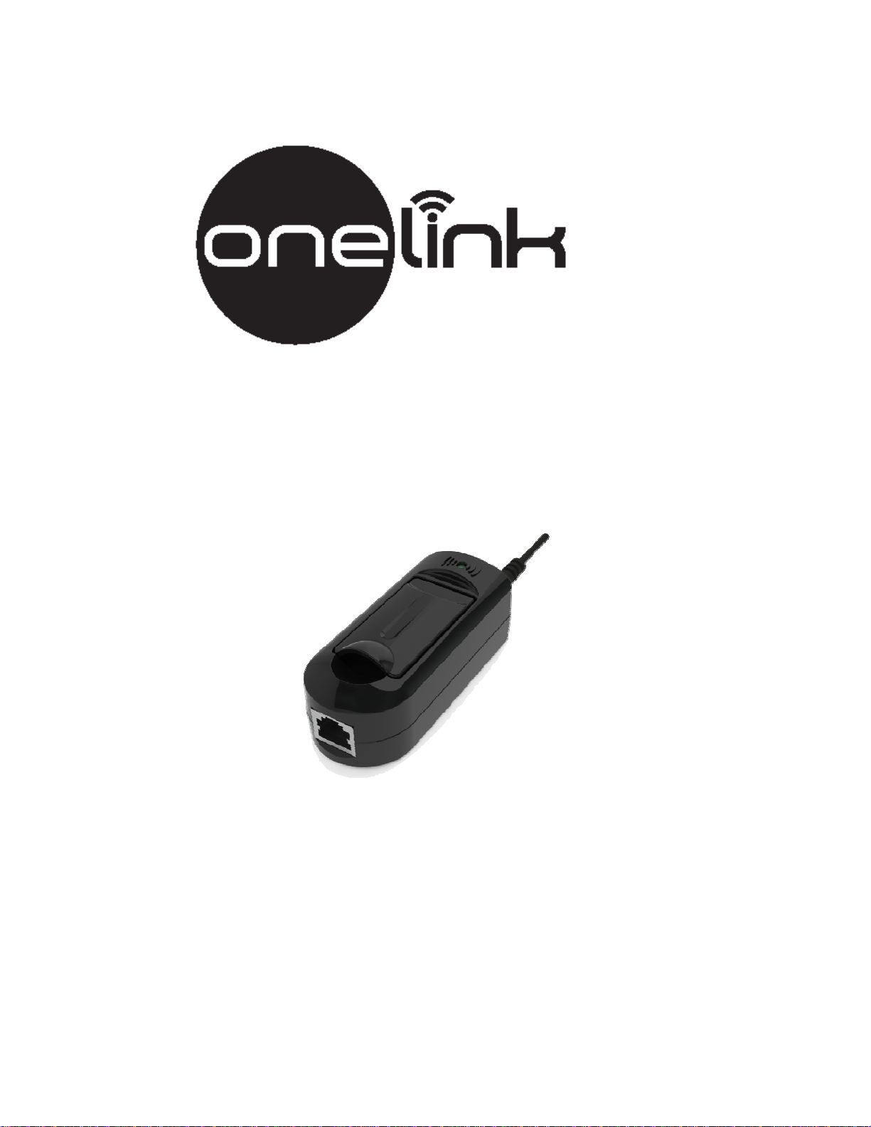
Equipment Description
The ONELINK Gateway has the following physical features. Locate them in the
accompanying diagram.
1) RJ-45 Ethernet jack
2) Power jack
3) Connection LED
4) Antenna

Installation
Location
Prior to installation, find a suitable location for placing the ONELINK Gateway. Use the
following recommendations to find such a location.
• The ONELINK Gateway can cover a 5000 square foot wood construction (typical
home) facility. This implies a circular coverage area of about 40 feet in radius. Place
the ONELINK Gateway in a central location so that this 40 foot circle covers the
entire facility.
• If your facility is larger than this, consider using two or more ONELINK Gateways to
provide adequate coverage.
• Best wireless coverage is achieved by placing the ONELINK Gateway at least 3 feet
above ground level.
• Note that large concentrations of metal, such as home appliances, water heaters,
fireplace hoods, or automobiles create a “radio shadow” which can disrupt wireless
connectivity. Avoid placing the ONELINK Gateway near such obstacles.
• If a wireless connection cannot be established between the ONELINK Gateway and a
ONELINK Wireless Ecosystem product, try moving the ONELINK Gateway horizontally
or vertically by a few feet. Moving the ONELINK Gateway will often shift “radio
shadows” around, which may be preventing the wireless connection from working.
Physical Installation
Follow these steps to install the ONELINK Gateway.
• Plug an Ethernet cable (CAT-5 or higher rated) into the RJ-45 Ethernet jack on the
ONELINK Gateway.
• Plug the other end of the Ethernet cable into an Internet router, or an Ethernet LAN
that is connected to the Internet.
• Plug the DC power adapter into an AC power socket, and plug the barrel connector
into the power jack of the ONELINK Gateway.
• Raise the antenna section of the ONELINK Gateway. Ensure that the antenna is
positioned at 90 degrees to the body of the ONELINK Gateway.
• You may optionally use double side tape to secure the ONELINK Gateway in its
operational location. Do this after verifying connectivity to all ONELINK Wireless
Ecosystem products.
Verifying Internet Connectivity
After connecting the ONELINK Gateway to power and Ethernet, the Connection LED should
turn on in a few seconds. This indicates that the ONELINK Gateway is connected to the
Internet and is ready to provide wireless connectivity to other ONELINK Wireless Ecosystem
products.
If the Connection LED does not turn on, please follow the steps in Appendix B,
troubleshooting, to check for problems.
Verifying Wireless Connectivity
To check for a radio connection, follow the instructions for installing the ONELINK Wireless

Ecosystem product you wish to connect to the Internet. Verify that the connection LED on
that product turns on. If it does, then the wireless connection is also working.
If the wireless connection is not working, please follow the steps in Append ix B for
troubleshooting the problem.
Configuration
The ONELINK Gateway is designed to be configuration free.
To configure the ONELINK Wireless Ecosystem product which is connected through the
ONELINK Gateway, follow the directions in the user guide for that product.
Appendix A: IP infrastructure requirements
The ONELINK Gateway connects to the Internet using the following protocols:
• Outgoing UDP connection to destination port 80
• Outgoing TCP connection to destination port 80
No configuration is required for any home broadband router. It may be necessary to open
these outgoing ports on an enterprise class router or firewall. Note that any deep packet
inspection looking for HTTP content will fail, as the ONELINK Gateway uses an encoded
ONELINK protocol for connectivity.
Appendix B: Troubleshooting
Use the following steps to resolve problems.
General problems
• Verify that the broadband and IP requirements are met.
• Check that the AC power socket that the ONELINK Gateway DC power adapter is
plugged into is providing AC power.
• Check that the DC power adapter is securely plugged into the ONELINK Gateway.
• Check to see that a PC or laptop is able to connect to the Internet.
• Verify that the PC or laptop is using DHCP to acquire an IP address (Windows IPV4
Properties: “Obtain an IP address automatically”).
Ethernet connectivity problems
• Check the router or switch that the ONELINK Gateway is connected to. Verify that
the connection or link light is turned on for the Ethernet jack connected to the
ONELINK Gateway. If the light is not on, there may be a problem with the Ethernet
cable.
Wireless connectivity problems
• Check that there is no large metal object between the ONELINK Gateway and the
ONELINK Wireless Ecosystem product you are trying to connect.
• Try moving the ONELINK Gateway by a few feet either horizontally or vertically.

Sometimes a horizontal or vertical movement of 3 or 4 feet is sufficient to escape a
wireless “radio shadow”.
• Try operating the ONELINK Wireless Ecosystem product close to the ONELINK
Gateway. This will require moving the produ ct temporarily. If wireless connectivity
works when the product is moved, consider re-locating the ONELINK Gateway to a
site closer to the product.
Limited Warranty- Onelink Gateway
BRK Brands, Inc., ("BRK") the maker of First Alert® brand and Onelink™ products warrants
that for a period of one year from the date of purchase, this product will be free from
defects in material and workmanship. BRK, at its option, will repair or replace this product
or any component of the product found to be defective during the warranty period.
Replacement will be made with a new or remanufactured product or component. If the
product is no longer available, replacement may be made with a similar product of equal or
greater value. This is your exclusive warranty.
This warranty is valid for the original retail purchaser from the date of initial retail purchase
and is not transferable. Keep the original sales receipt. Proof of purchase is required to
obtain warranty performance. BRK dealers, service centers, or retail stores selling BRK
products do not have the right to alter, modify or any way change the terms and conditions
of this warranty.
This warranty does not cover normal wear of parts or damage resulting from any of the
following: negligent use or misuse of the product, use on improper voltage or current, use
contrary to the operating instructions, disassembly, repair or alteration by anyone other
than BRK or an authorized service center. Further, the warranty does not cover Acts of God,
such as fire, flood, hurricanes and tornadoes or any batteries that are included with this
unit.
BRK shall not be liable for any incidental or consequential damages caused by the breach of
any express or implied warranty. Except to the extent prohibited by applicable law, any
implied warranty of merchantability or fitness for a particular purpose is limited in duration
to the duration of the above warranty. Some states, provinces or jurisdictions do not allow
the exclusion or limitation of incidental or con sequential damages or limitations on how long
an implied warranty lasts, so the above limitations or exclusion may not apply to you. This
warranty gives you specific legal rights, and you may also hav e other rights that vary from
state to state or province to province.
How to Obtain Warranty Service
For customer service, technical support, and warranty claims, contact our Customer Support
Center at 1-800-323-9005 Monday - Friday 7:30am-5:00pm Central Standard Time
.
Registration
Register your product at: http://onelinkhome.com
© 2011 BRK Brands, Inc. All rights
reserved. Distributed by BRK Brands,
Inc. 3901 Liberty Street Road,
Aurora, IL 60504-8122
ONELINK
First Alert
used under license.
MODEL: OLGATEWAY
M08-0227-002
®
is a registered trademark of BRK Brands, Inc.
®
is a registered trademark of the First Alert Trust

 Loading...