

Page 1

FUNDAMENTALS OF
MUSIC TECHNOLOGY
Volume One:
The ARP 2600
S•Y•N•T•H•E•S•I•Z•E•R
S E C O N D E D I T I O N
A Pedagogic Work in Elementary Synthesis
With Sampling and Example CD
by
S A M U E L E C O F F
Page 2

FUNDAMENTALS OF
MUSIC TECHNOLOGY
Volume One:
The ARP 2600
S•Y•N•T•H•E•S•I•Z•E•R
S E C O N D E D I T I O N
A Pedagogic Work in Elementary Synthesis
With Sampling and Example CD
by
S A M U E L E C O F F
Page 3

Secret Society Pr oductions
Fundamentals of Music Technology Volume One: The ARP 2600 Synthesizer
Copyright ©& 2000 by Samuel Wells Ecoff. All Rights Reserved.
P
Except as permitted under the United States Copyright Act of 1976, no part of
this publication may be reproduced or distributed in any form or by any means,
or stored in a data base or retrieval system, without the prior written permission
of the author . If you would like to use excerpts from this book as part of a web
page, call me; we’ll talk. :-) The author hereby grants permission to the reader
to make copies of Appendix T wo (patch sheets for the 2600 and ARP sequencer)
as needed, as long as they are used for personal purposes, and not for profit.
T ypeface: Times
This book is printed on acid-free paper.
CD LICENSING AGREEMENT
Permission is hereby granted to create samples from the audio CD included with this book. However, by
breaking the seal on the CD casing, the user agrees to the following terms: The sounds and samples on
this disc are licensed, not sold to you. You may use the sounds and samples found on this disc in a
commercial or non-commercial recording without paying any additional license fees. However, you must
strictly adhere to the following crediting guidelines on any music recording that uses material from the
enclosed CD:
In the written materials accompanying your music release, you must include the following courtesy
credits using this wording strictly:
ARP 2600 samples courtesy of Sam Ecoff of Secret Society Productions
Use of these sounds is limited to use musical context, and these sounds must not be left exposed where
they could be easily sampled by a third party. This license of free use is granted exclusively to the original
purchaser of this disc and book, and is non-transferrable.
Any redistribution of this material in any form or by any means is strictly prohibited.
®
1 1.70
2 2.03
3 1.73
4 3.79
6 1.67
8 2.82
10 1.32
13 1.33
15 1.50
17 1.38
19 1.22
21 1.12
23 2.11
25 1.31
27 1.23
29 1.32
31 1.22
33 1.19
35 1.10
36 1.10
37 1.04
38 1.06
39 1.08
40 1.01
41 1.3
42 1.1
ii
Page 4

This book is dedicated to all of the people that love
this wonderful instrument as much as I do; to the
people who know that the patch isn’t complete until
every available patch cord has been used.
iii
Page 5

TABLE OF CONTENTS
Table of Contents...............................................................................................................................iv
Listing of Tracks on CD ....................................................................................................................vi
How the CD was Recorded ...............................................................................................................x
Prefaces..............................................................................................................................................xi
Thank You..........................................................................................................................................xiii
About the Format of this Book.......................................................................................................... xiv
UNIT ONE: INTRODUCTION AND OSCILLATORS
Section One: General Controls.......................................................................................................... 001
Experiments........................................................................................................................... 009
Review Questions ................................................................................................................. 010
Section T wo: VCO-1..........................................................................................................................011
Experiments........................................................................................................................... 016
Review Questions ................................................................................................................. 017
Section Three: VCO-2 ...................................................................................................................... 018
Experiments........................................................................................................................... 028
Review Questions.................................................................................................................. 029
Section Four: VCO-3.........................................................................................................................030
Experiments........................................................................................................................... 034
Review Questions.................................................................................................................. 035
UNIT TWO: MODIFYING THE SIGNAL
Section Five: Noise Generator ...........................................................................................................036
Experiments........................................................................................................................... 040
Review Questions.................................................................................................................. 041
Section Six: The VCF .......................................................................................................................042
Experiments........................................................................................................................... 052
Review Questions.................................................................................................................. 054
Section Seven: ADSR & AR Generators...........................................................................................055
Experiments........................................................................................................................... 060
Review Questions.................................................................................................................. 062
Section Eight: The VCA....................................................................................................................063
Experiments........................................................................................................................... 068
Review Questions.................................................................................................................. 069
iv
Page 6

TABLE OF CONTENTS
UNIT THREE: FINISHING TOUCHES
Section Nine: The Mixer Section and Reverberator..........................................................................070
Experiments........................................................................................................................... 073
Review Questions.................................................................................................................. 074
Section Ten: The Internal Clock, Electronic Switch, and S/H Circuits.............................................075
Experiments........................................................................................................................... 080
Review Questions.................................................................................................................. 081
Section Eleven: The Ring Modulator, Preamp and Envelope Follower ...........................................082
Experiments........................................................................................................................... 088
Review Questions.................................................................................................................. 090
UNIT FOUR: ADDITIONAL MODULES
Section T welve: The Voltage Processors........................................................................................... 091
Experiments........................................................................................................................... 095
Review Questions.................................................................................................................. 097
Section Thirteen: Keyboard Controls................................................................................................ 098
Experiments........................................................................................................................... 106
Review Questions.................................................................................................................. 108
Section Fourteen: Patch Analysis and Diagramming........................................................................ 109
Experiments........................................................................................................................... 118
Review Questions.................................................................................................................. 118
Section Fifteen: Further experiments with the ARP Sequencer.........................................................119
Experiments........................................................................................................................... 123
Review Questions.................................................................................................................. 124
Glossary..............................................................................................................................................125
Index.................................................................................................................................................. 136
Bibliography.......................................................................................................................................138
About the Author................................................................................................................................139
APPENDICES
Appendix One: Additional Resources for students of Electronic Music...........................................140
Appendix Two: ARP 2600 + ARP sequencer patch sheets................................................................143
v
Page 7

CD TRACK LISTING
Track Page Note(s) Description
SECTION 2
1 12 C1-C5 VCO-1 Saw Wave, VCO-1 Square Wave
2 12 C3 VCO-1 is tuned to VCO-2 (Saw Wave both)
3 15 LF VCO-1 in LF mode is gradually increased until it is audible. Saw
then square wave
SECTION 3
4 22 -- VCO-1 FM’d by a saw wave from VCO-2 in LF mode.
5 24, 28 -- Sidebands
6 25, 28 C1-C5 PWM patch where VCO-1 causes a pulse width sweep.
7 18, 28 C1-C5 Saw, Pulse, Sine, Triangle waves from VCO-2.
8 28 C3 Pulse width is manually swept.
9 28 -- FM patch, all parameters swept one by one.
10 28, 106 C1-C5 FM patch, VCO-2 produces interval leaps with square wave.
11 27, 28 C1-C5 Phat Tuning VCO-1 and 2 with saw waves, the square waves.
SECTION 4
12 31, 34 C1-C5 Double FM modulation. VCO-1 and VCO-2 modulate VCO-3
13 32, 34 -- Cross FM modulation patch. VCO-2 and VCO-3 modulate each
other in the audio range. Second time deeper modulation than
1st.
14 32, 34 -- Series modulation. VCO-1 --> VCO-2 --> VCO-3.
15 34 C3-C4 All three VCOs tuned in intervals. Major and minor chords on
each white key.
SECTION 5
16 37 C1-C5 Noise Generator FMs VCO-3. Saw Wave timbre. First with little
FM, second time with a lot of FM
17 39 C1-C5 Noise Generator PWMs VCO-2. First with small modulation
depth, second time with greater modulation depth.
18 40 -- Noise Generator’s raw output, noise frequency slider is then swept.
SECTION 6
19 45, 52 C1-C5 Filter sweeps close on a saw wave from VCO-2
20 46, 52 C1-C5 Resonant filter sweeps close on saw waves from VCO-1 and 2
21 47 C1-C3 The VCF is made to self-oscillate. Notice how tuning drifts.
22 48 C1-C5 All White keys played key tracking on filter disabled. VCO-1, 2,
and 3 in phat tuning.
vi
Page 8

CD TRACK LISTING
Track Page Note(s) Description
23 49 C1-C5 Highpass filter sweep (JP-8000) followed by resonant highpass
filter sweep (JP-8000)
24 49 --- This track has intentionally been left blank due to an error in
printing in the book.
25 52 C3 Filter’s Fc is modulated by VCO-2’s sine output in the audio
range. Sidebands result.
26 52 C2. C3, C4 Keyboard CV no longer controls VCO, but still controls Fc.
27 52 C1-C5 VCO-1 saw wave (LF) modulates Filter’s Fc while harmonics of
a saw wave from VCO-2 are accentuated by heavy resonance.
Set mod rate as low as possible.
SECTION 7
28 60 C1-C5 ADSR EG FMs VCO-1, 2 and 3 (mixed waves) Only attack stage
is used.
29 60 C1-C5 Same as track 28, but just decay.
30 60 C1-C5 Same as track 28, but just sustain. Sustain level is manually
changed during this experiment. (Release on gate increased)
31 60 C1-C5 Same as track 28, but just release + sustain. Mod depth increased.
32 60 --- Noise generator is put through filter, first w/o resonance, then
with. Percussion sounds are created.
33 60 C1-C5 All VCOs in phat tuning, various ADSR settings, with and with-
out resonance. VCF controlled by ADSR.
34 60 C1-C3 All VCOs in saw wave, then square, just decay set very short
yields a good bass sound. First without resonance, then with.
35 61 C1-C3 Same as 34, but with just sustain.
36 61 C1-C3 Same as 34, but with just release + a little sustain.
37 61 --- AR FMs all three VCOs while ADSR modulates filter Fc.
38 61 --- ADSR FMs all three VCOs while AR modulates filter Fc.
39 61 C1-C5 Pitch of all three VCOs bends up to proper pitch whenever a note
is played.
40 61 C1-C5 ADSR generator FMs all three VCOs in different amounts while
AR controls VCF gating.
41 61 C1-C5 ADSR generator PWMs VCO-2
SECTION 8
42 64, 68 C3 VCO-2’s saw is gated first by VCF, then by VCA.
43 65, 68 C1-C3 All VCO’s gated by VCA, controlled first with Exponential in-
put, then linear input
44 66, 68 C1-C5 VCO-2 in LF mode controls VCA gain to create tremolo. VCO-
1 and 3 produce square waves, gated by VCF
45 66 C3 VCO-2 in LF mode modulates VCA gain quickly and deeply
enough to produce sidebands.
vii
Page 9

CD TRACK LISTING
Track Page Note(s) Description
46 68 C1-C5 VCO-2 and 3 fed into VCF controlled by AR EG. VCF fed to
VCA controlled by ADSR generator. Then, same patch, but VCF
controlled by ADSR and VCA controlled by AR.
SECTION 9
47 73 C1-C5 VCO-1 is patched directly to the reverberator.
48 73 --- Noise generator, gated by VCF is sent to mixer. Mixer sends to
reverberator. Different amounts of reverb are demonstrated.
49 73 --- The springs in the reverb tank are intentionally jostled.
50 72, 73 --- Noise generator, gated by the VCF is reverberated too heavily,
and a watery sound results.
SECTION 10
51 77, 80 C1-C5 Auto panning patch created with electronic switch
52 78 C1-C5 One LFO (VCO-1 saw wave) alternately modulates VCO-2 & 3.
53 78, 80 C2-B3 Switching patch: Pulsing sound is created by switching between
patch and silence.
54 78, 80 C1-C5 Switch alternates between two oscillators tuned differently , then
between oscillators and noise generator. With filter sweep.
55 78, 80 C1-C5 Switch switches between two LFOs modulating one VCO. One
LFO is in the audio range,
56 79, 80 --- S/H unit samples white noise and modulates VCO-1 and 2.
57 79, 80 C1-C5 VCO-2 & 3 sent to filter. VCF’s Fc is modulated by the S/H unit
which is sampling a slow-moving saw wave from VCO-1 in LF
mode.
58 79 --- S/H FMs VCO-1 & 2. Saw wave from VCO-3 is sampled to pro-
duce running chromatic and whole tone scales.
59 79, 80 --- Complex feedback patch in which output of VCF is fed back into
S/H unit which in turn modulates Fc and FMs VCOs
SECTION 11
60 85 C2 Person speaks into microphone connected to preamp and enve-
lope follower . Envelope follower is then used to FM VCOs, modu-
lates the VCF’s Fc, and finally the gain on the VCA.
61 86, 89 --- Ring Modulator is used to create highly metallic sounds
62 86, 89 C1-C5 Ring modulator is used to bring out high frequencies in this patch.
63 86 C1-C5 Square wave from VCO-1 in LF mode creates pulsing effect.
64 86, 89 --- Sound with lots of harmonics starts in AUDIO position, then
moves to DC position. Pitch of VCO-2 is swept upwards.
65 87, 89 --- VCO-1’s frequency remains constant while VCO-2’s frequency
is swept upwards. Both are connected to the ring modulator.
66 88 --- A drum loop from a CD is put into the preamp, then filtered and
distorted.
viii
Page 10

CD TRACK LISTING
Track Page Note(s) Description
67 88 C3 A sine wave from VCO-2 is amplified until it is clipped and turned
into a square wave.
68 88 C1 The output of a CD player is preamped, then fed to the envelope
follower before going to the FM inputs on the VCOs, the VCF,
and finally the VCA.
SECTION 12
69 92, 95 C scale VCO-1 reacts normally while the keyboard CV going to VCO-2
is inverted. Ascending C scale, then short melodic passage.
70 92, 95 C1-C5 Inverted envelope FM’s VCOs, modulates Fc, and finally modu-
lates VCA’s gain, each in turn.
71 92, 95 --- VCO-1’ s saw wave in the sub-audio range is inverted and used to
FM VCO-2.
72 94, 96 C1-C5 The keyboard CV is routed through the lag processor with a large
99, 106 lag time to produce portamento. Pitch slides from C1 to C5 and
back again.
73 96 C2 A lagged square wave from VCO-1 in LF mode FMs VCO-2.
SECTION 13
74 101 C1 + C scale Duophonic patch in which both voices share the VCF for gating.
75 101 C1 + C3 C3 is held while C1 is tapped. The lower voice switches from
one oscillator to two, illustrating how unmusical this can be.
76 106 C2 Vibrato is created using the keyboard’ s LFO. All parameters are
swept, including vibrato delay.
77 106 C3 Repeat switch causes constant retriggering.
78 107 C Scale Trigger switch on single. Scale is played legato up and down.
79 107 C scale Trigger switch on multiple. Scale is played legato up and down.
80 107 C Scale Trigger switch on multiple, portamento on, time minimum.
SECTION 14
81 112, 114 --- FM patch illustrated on page 112.
82 115, 11 --- FM patch illustrated on page 115.
83 117 --- A wild patch with lots of feedback, and modulation occurring in
the audio range. The S/H unit samples the VCA’s output.
SECTION 15
84 119 --- The frequency of VCO-1 is swept upwards first with the INI-
TIAL FREQUENCY control, then under control of the sequencer .
The voltage quantizer causes it to ascend in chromatic half steps.
85-93 Miscellaneous sequencer patches
ix
Page 11

HOW THE CD WAS RECORDED
The audio CD which accompanies this book was recorded by connecting the left and right outputs of
the ARP 2600’s mixer section to a Mackie LM-3204 mixer. The incoming sounds were compressed
slightly with a Behringer Composer compressor before being routed to a Digidesign 882 audio interface connected to a Pro Tools|24 system. The ARP 2600 was then recorded into Mark of the Unicorn’s
Digital Performer 2.61MT hard disk recording software running on a Macintosh G3. It was then edited
so that each example began and ended in exactly the right spots and was mastered with plugins from
TC Works and MOTU. Other than the aforementioned gentle compression, no effects were applied to
the incoming sounds from the 2600.
The 2600 was played part of the time from its own keyboard and part of the time from a Fatar SL-880
mother keyboard and Digital Performer through a Paia MIDI2CV8 converter. Many of the melodic
samples were progammed into Digital Performer to insure timing accuracy and consistency. While
purists may argue against the use of MIDI in controlling an ARP 2600, the author was left with no other
choice as a capacitor in the keyboard’s control panel went bad only a week before the final recording
session for the CD, and the repair unfortunately could not be completed in time for the final recording
session. (Special thanks to T im Smith of The Audio Clinic who restored the keyboard control panel to
working condition).
When melodic patches were recorded (i.e. pitched sounds) an effort was made to make them available
at many different pitches for reader who may wish to sample them. These pitches can then be used to
create a multisample which yields the highest amount of accuracy in sample playback.
The samples associated with Section 15, were created using the ARP sequencer rather than Digital
Performer running through the Paia converter . As a result, some drift is noticable in tuning and timing
stability .
x
Page 12

PREFACE
to the first edition
This book is the culmination of years of work and study into the pedagogy of music technology, and I
fear it is also just the beginning, as there will always be more to learn about this exciting new field. I
have little hope of these volumes catching on as standard works, as they are highly instrument-specific.
However, I feel that they have pedagogic merit, and where all else fails, they could even substitute for
an owner’s manual in a pinch.
This book is intentionally printed on every other page so that the student may have a convenient place
to take notes, write questions about readings, and record observations during experiments.
As with any field that is in its infancy and is still rapidly evolving, it seems that there is no good way to
go about writing about music technology. Either a text is so instrument-specific that it becomes outdated very quickly (within five years or so) or it is so general that it is of little merit to the beginning
student. I have elected to opt for the former path, as I have consistent access to the instruments in
question. While this is of the greatest value to me, it is of very little assistance to anyone else who might
be interested music technology in general.
Because I have always taught these lessons in very small groups or as private lessons, I have always
taught them using an outcome-based approach. I have given students a reasonable number of chances
to correct their mistakes and improve their knowledge, as well as improving their grade. I have required my students to pass each quiz at a minimum of the eightieth percentile.
So, I commend this book to the reader... Get what you can out of it. For students who are about to study
music technology privately and will be using these tomes as a course book, I can only say.... be pre-
pared in every way possible! Also be forewarned that questions that are missed on quizzes have a nasty
habit of showing up on the final examination.
Sam Ecoff
January Seven, 1999
Wales, Wisconsin
xi
Page 13

PREFACE
to the second edition
Over the course of two years of teaching music technology, I have stumbled (mostly blindly) upon
several observations as to which students are generally successful in their studies of electronic music
and which students generally fall by the wayside. It seems that it is the students who have a passion
music technology are the students that are most apt to succeed. This observation would seem really
rather obvious at first, but the more one contemplates it, the more ramifications it has.
First, students need to make a commitment to music technology if they are to study it. Although there
is a great deal to know about other musical instruments, piano for instance, relatively little has changed
in the design and playing technique of the piano in the last ten years. In the music technology industry ,
the last ten years have seen one revolution after another including the rise of the home MIDI studio,
digital audio recording for the average musician, and finally, the rise of the complete home project
studio which is actually able to compete in terms of quality with major production facilities. Because
technology is evolving at such a rapid pace, students must be even that much more dedicated to the task
of mastering as much information possible. In this wonderful day of instant information, gathering
information is no longer the great challenge to the student, but rather taking time and finding the energy
to master all of the information which is at the student’s fingertips.
The second observation I have made is that some students wish to learn about music technology in the
‘better-faster-cheaper’ mode, which accomplishes little. To these students, understanding the mechanics and theory of one oscillator frequency modulating another is a complete waste of their time, and
they would much rather just call up a preset on a modern synth which will in their minds do that work
and thinking for them. One must understand that there are always greater possibilities when one can
understand the theory of synthesis which stands behind the sounds, and when a musician is given full
access to all of the parameters of sound available instead of three knobs for ‘realtime control’ and a
bunch of ROM presets sporting today’s latest flavors.
Indeed, there is nothing wrong with using preprogrammed musical patterns and combining them with
other sounds to create a new kind of music, but there is a fine line between a musician and a technician.
While the technician assembles premade parts and works logically with machines to produces sound, a
musician will actually create new loops and adds the dionisian element of the creation of new sound.
As synthesists, computer operators, composers, arrangers, and music technologists, it is important to
keep both the hat of the technologist and the hat of the musician at the ready so that we may freely and
readily switch between the two. Perhaps that is the most important part of music technology: It is not
about being one-dimensional or about confining oneself to a single role. It is about exploring all of the
possibilities and about trying all of the parameters. When access to parameters is denied, either by
companies who produce equipment advertised to fill the role of pro gear or by people who shut out
different possibilities in music technology, it is the music that suffers.
xii
Page 14

THANK YOU
This book is and has been a collaborative effort, as many such large undertakings are. I would be truly
remiss if I missed this opportunity to thank the following people for their assistance in completing this
text. It is, I feel, important to note that many of them performed their services entirely gratis because of
their love of the subject.
I would like to thank Dr. Michael Cunningham who introduced me to the ARP 2600 Synthesizer during
my undergraduate degree at the University of Wisconsin-Eau Claire. He also deserves credit for coining the term “redundant patch.”
I also owe a great debt of thanks to my loving fiance, Kara for all of the hours she spent proofreading
and inputting corrections on a subject which she cares about only for my sake. She was also incredibly
helpful during the recording sessions for this book, ‘wo’-manning the digital audio workstation to
leave me free to concentrate on the creative aspect of creating patches.
I must also thank my internet friend Roger Lesinski whom I have never met, but has provided wonderful insights and new thoughts into the technical side of this book, and for his great proofreading skill.
This book would still be sitting gathering dust on a shelf as a twenty-one page outline if it were not for
the many students whom I used as guinea pigs while I was developing this book. I owe them a great
debt of thanks for their continued patience and also their assistance in proofreading. (It is sometimes
embarrassing to admit that 10-year old students found many errors that I and the rest of my proofreading team missed!)
I would be remiss if I forgot to mention Ihor “E” Tanin of “E” Lectronix Rock ‘n Roll Hospital in New
Berlin Wisconsin. Not only did he restore my ARP 2600 at a fantastically low price, he also put up with
my phone calls three to four times per week for several months. I also owe a great debt to Timothy
Smith of The Audio Clinic/Weyer-Smith Labs in Billings, Montana. He did a wonderful job of repairing my broken 3620 keyboard, and his knowledge of the 2600 was truly amazing and invaluable.
Finally, I would like to thank my uncle, David Reed who ever so kindly supplied me with the paper I
needed to print the very first copy of this book when I was too poor to purchase paper myself, and to my
parents who have always supported my efforts, and who put up with years of bleeps and bloops coming
from their basement while I learned how NOT to program synthesizers. To all of these people I am
grateful!
xiii
Page 15

ABOUT THE FORMAT OF THIS BOOK
This book has many facets and serves many purposes to many people. While it is primarily geared
towards an academic setting where the basic concepts of subtractive synthesis may be introduced, it
can also be of value in other ways, which are best left to be discovered by the reader.
This book does not start from ground zero. It assumes that the reader has a small amount of knowledge
in the area of basic acoustics. It is important to understand how sound travels, the concept of harmonics, frequency and how it is measured, basic waveforms and their harmonic content. It is common
practice to begin a book such as this with a short chapter on acoustics, but since there are so many
excellent books which cover these topics on a very accessible level, these topics have been omitted
from this book. For persons interested in reading these books (it never hurts) a short list can be found in
Appendix One.
The book itself is grouped into five units. These units are then split into parts called sections. I felt that
this was a more appropriate term than chapter since modular synthesizers are sectional devices by
nature. Each section has several subheadings and illustrations. Following each section of text is a set of
experiments that should be performed on the instrument. There is no substitute for hands-on experience. Following the experiments are a set of review questions and a list of all of the important terms
which were introduced in that section. These will primarily be of interest to persons in an academic
setting, but can also serve as a memory refresher for the casual reader.
The rear of the book features a glossary of terms, including some background terms which are not
included in the text itself. An index is also present for easy reference of terms and concepts.
This book includes an audio CD which contains sounds played on an ARP 2600. This disc serves three
purposes. First, it allows people to check the results of their experiments to see if they have come up
with the correct sound. Secondly , it allows people who do not have access to a 2600 to hear the results
of each audio experiment and some examples in the text. It will also allow them to hear what this
marvelous instrument can do. Finally, it can be used as a source of analog synthesizer samples for a
sampler . (Please read the sample use agreement on page ii if you intend to use the CD for this purpose.
The license granted to you is fairly unrestrictive, but there are certain legal obligations which must be
met if the disc is to be used for this purpose.)
One final note about this book is that in many of the examples, the subject in the experiment is referred
to as ‘Bob’ or ‘Wendy .’ This is in honor of Dr. Robert Moog and Wendy Carlos. Dr. Moog invented the
first commercially available synthesizer and invented many of the modules described in this book.
Wendy Carlos is an excellent musician/composer/inventor whose wonderful recording “Switched-On
Bach,” performed on Bob Moog’s Series IIIp synthesizer, still holds the record as the best selling
classical album of all time.
xiv
Page 16
SECTION
1
GENERAL CONTROLS
INTRODUCTION AND BACKGROUND
The ARP 2600 was designed and manufactured at a point in time when synthesizers had just emerged
as a musical instrument (the late 1960’s), and most people had no idea how to use and program them.
Because of this, the ARP company designed a synthesizer whose primary purpose was to teach people
about synthesizers. The ARP 2600 was manufactured from 1970 to 1980, which is a very long production run for a synthesizer by today’ s standards. Its designers did everything they could to make it easy
to understand. For instance, all of the controls are laid out so that when creating sounds, they start at the
left side of the synthesizer and move towards the right. This is the way most sounds are created, just
letting the electronic signals flow from left to right. The ARP 2600 is much like an assembly line in this
way. Each part adds to or changes the sound a little bit until a finished sound emerges at the end. The
2600’s designers also used white diagrams on the
instrument’s front panel to attempt to show users
where signals were flowing within the instrument.
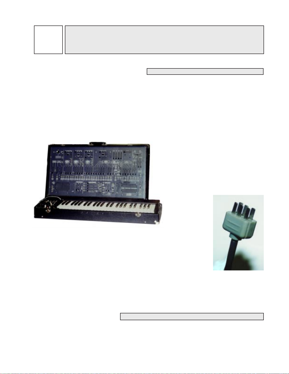
In Figure 1-1, one can see that the ARP 2600 is
actually two separate parts: A keyboard unit and a
cabinet unit. The keyboard must be connected to
the cabinet in order for the keyboard to function,
because the keyboard
draws power from
the cabinet. However, it is entirely
Figure 1-1 The ARP 2600
without the keyboard attached. It still functions perfectly well. In fact, many
of the experiments in this book do not require the keyboard.
possible to use the
ARP 2600’ s cabinet
The connection to the keyboard is established with a single cord. The cord is
permanently attached to the keyboard at one end, and has a multipin plug at
the other end. This design was changed several times by ARP, and it is entirely
possible to find keyboards made for the 2600 which do not follow this design.
(e.g. some earlier models have cables which can be unplugged from both ends.)
A model 3620 keyboard was used for purposes of this book. Notice in Figure 1-2 how many connectors
there are on the plug which connects the keyboard, and keep this information in mind. For now , it is just
necessary to know that the keyboard receives power from the cabinet through this cable.
Figure 1-2: The keyboard’s
multipin connecting cable
THE BALANCE OF POWER
The ARP 2600 gets power from a household electrical outlet via a three-prong cord which plugs into
the right side of the cabinet. The pins are aligned in such a way that the cord cannot be plugged in
upside down. However, the plug that connects with the AC outlet is not polarized and can be connected
in either direction.
001
Page 17
002 - SECTION ONE: GENERAL CONTROLS
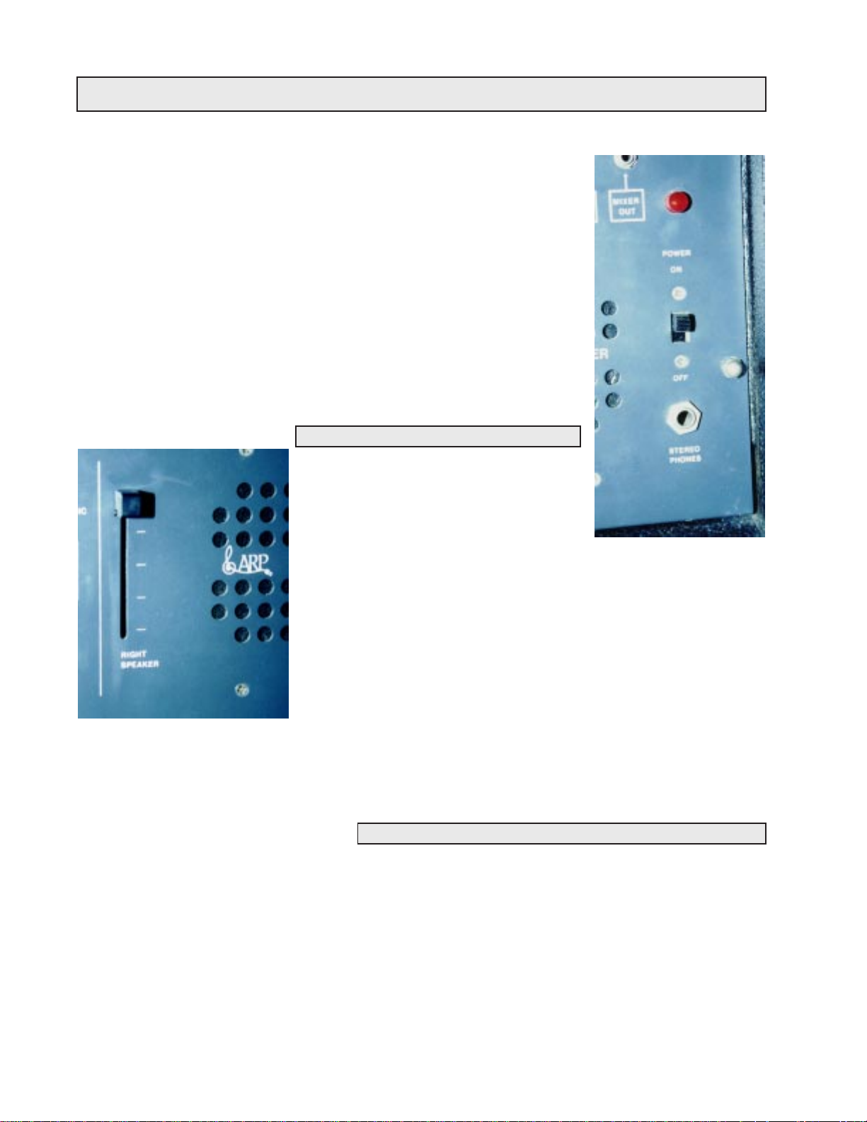
The main power switch interrupts incoming electricity so that the ARP cabinet and its keyboard can be switched on and off. It is located at the lower
right hand corner of the cabinet, just above the headphone jack. (See Figure
1-3) Notice that when the synthesizer is switched on, the red light above the
switch goes on. This is the only visual indication that the power is on. There
is not a separate on/off switch for the keyboard; it is switched on when the
cabinet is switched on. When turning the synthesizer on, it is always a good
idea to make sure that the synthesizer has been zeroed (see below) and that
there are no additional cables connecting the 2600 to other devices in the
studio. This insures that no damage will be done to the synthesizer or other
studio devices, and that the synthesizer isn’t gong to make some sort of a
terrible squealing sound or something worse.
SPEAKING OF WHICH
One can see that the ARP 2600 has builtin speakers. Each speaker has its own volume control. This control is pictured in
Figure 1-4. The ARP also has a quarterinch jack into which one can plug a pair of
stereo headphones. The headphone jack is
located just below the main power switch
on the cabinet. (See Figure 1-3) Although it accepts stereo headphones,
the ARP 2600 is a monaural synthesizer. (I.e. the same signal is fed to
both the right and left earphones) The only exception will be explained
in Section 9.
Figure 1-3: The ARP 2600’s
headphone jack, power
switch, and indicator light
On some synthesizers, plugging headphones in will interrupt sound
Figure 1-4: A speaker volume
control
the ARP was designed before many of the professional standards were developed, and plugging in
headphones cuts off the speaker’s output entirely, even if the volume level is set as loud as possible.
going to the speakers. On most professional-level synthesizers, this
won’t happen, (most pro-level synthesizers don’t have speakers) but
ZEROING THE SYNTHESIZER
Sometimes when a student starts to use the synthesizer, someone else has been using it before them.
This can make working on the synthesizer very frustrating, since one doesn’t know how the last person
was using it, and some switch or fader might be set in a way that would keep the synthesizer from
functioning the way it normally would. It is best to return all of the knobs, faders, and switches to their
original position, and to remove all patch cords (see page four) from the synthesizer to prevent this sort
of frustration. This is called zeroing the synthesizer. The synthesizer should be zeroed each time one
begins using it. When attempting a new sound, it is also wise to zero the synthesizer , as the instrument
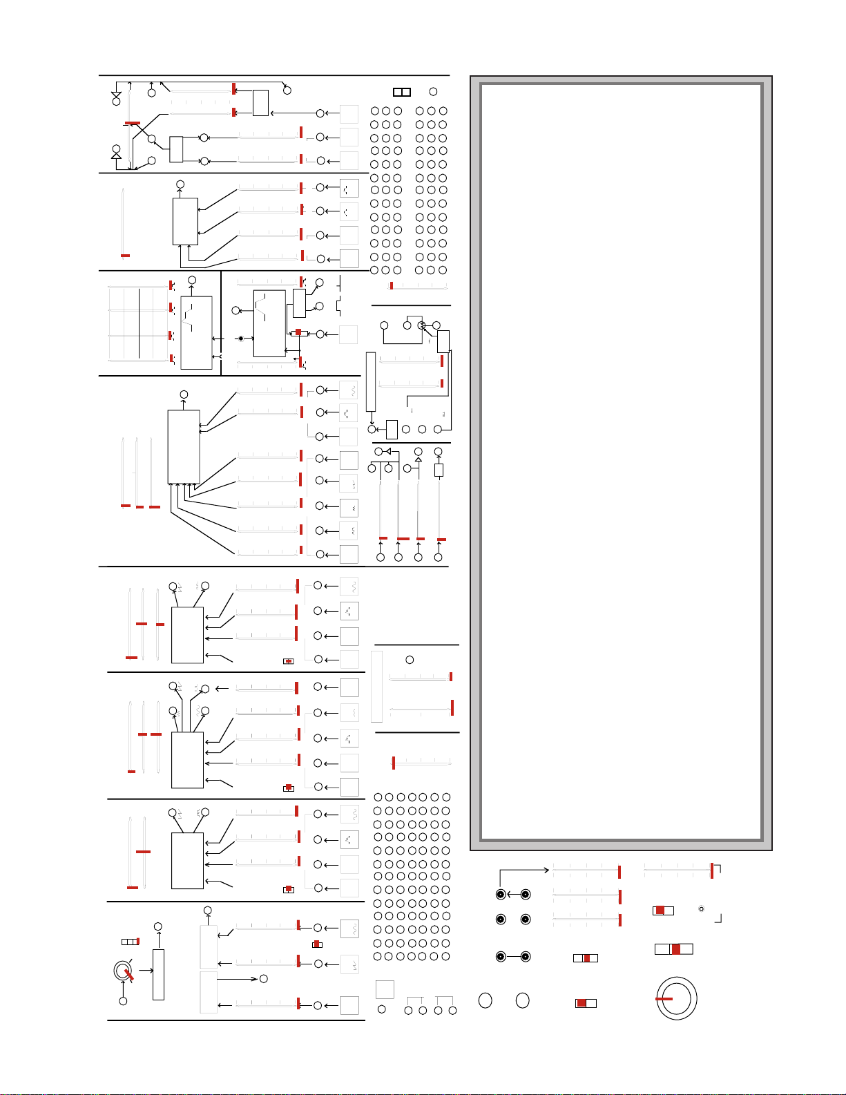
might not behave the way one expects because of some earlier setting. Diagram 1-1 on page 3 illustrates the proper settings of each knob, switch, and slider when zeroed. Notice that all patch cords have
been removed.
Page 18
RANGE
X1000
X100
X10INGAIN0MAX
PREAMPLIFIER
OUT
ENVELOPE
FOLLOWER
OUT
PRE-
AMP
RING
MODULATOR
OUT
VCO
1
VCO
2
AUDIODCVCO
2
S/H
OUT
KBD
CV
ADSR
KBD
CV
OUT
MULTIPLE
LEFT
SPEAKER
INITIAL OSCILLATOR FREQUENCY
10 100 1KHz 10KHz
.03 .3 3.0 30
FINE TUNE
VOLTAGE
CONTROLLED
OSCILLATOR
VCO-1
AUDIO
L F
KBD ON
KBD OFF
FM CONTROL
OUTPUTS
SAWTOOTH
SQUARE
VOLTAGE
CONTROLLED
OSCILLATOR
VCO-2
AUDIO
KBD ON
KBD OFF
FM CONTROL
OUTPUTS
S/H
OUT
KBD
CV
ADSR
VCO
1
NOISE
GEN
PULSE WIDTH
MODULATION
INITIAL OSCILLATOR FREQUENCY
10 100 1KHz 10KHz
.03 .3 3.0 30
FINE TUNE
PULSE WIDTH
10% 50% 90%
TRIANGLE
SAWTOOTH
PULSE
PWM
INITIAL OSCILLATOR FREQUENCY
10 100 1KHz 10KHz
.03 .3 3.0 30
FINE TUNE
PULSE WIDTH
10% 50% 90%
VOLTAGE
CONTROLLED
OSCILLATOR
VCO-3
OUTPUTS
SAWTOOTH
AUDIO
L F
KBD ON
KBD OFF
FM CONTROL
KBD
CV
ADSR
NOISE
GEN
VCO
2
PULSE
NOISE GENERATOR
NOISE
GEN
OUTPUT
MAX
MIN
WHITE
PINK
LOW
FREQ
SINE
VOLTAGE
CONTROLLED
FILTER/RESONATOR
VCF
AUDIO
OUTPUT
KBD
CV
ADSR
VCO
1
NOISE
GEN
INITIAL FILTER FREQUENCY
10 100 1KHz 10KHz
FINE TUNE
RESONANCE
MIN MAX
CONTROL
RING
MOD
VCO
2
VCO
3
VCO
2
ATTACK
DECAY
SUSTAIN
RELEASE
ENVELOPE
TRANSIENT
GENERATOR
OUTPUT
ATTACK
TIME
DECAY
TIME
SUSTAIN
VOLTAGE
RELEASE
TIME
A
DSR
ATTACK
RELEASE
ENVELOPE
TRANSIENT
GENERATOR
OUTPUT
ATTACK
TIME
RELEASE
TIME
A
R
MANUAL
START
S/H
GATE
KEYBOARD
GATE/TRIG
TRIG
GATE
AUDIO
VCF
ADSR
AR
CONTROL
LINEAR
EXP’L
SAMPLE & HOLD
NOISE
GEN
VOLTAGE
CONTROLLED
AMPLIFIER
OUT
INITIAL GAIN
ABC
ELECTRONIC
SWITCH
S/H
OUT
EXT
CLOCK
IN
INT
CLOCK
OUT
LEVEL
RATE
INTERNAL
CLOCK
RIGHT
SPEAKER
ARP
MODEL 2600
AUDIO
VCF
MIXER
OUT
MIXER
PAN
LEFT
INPUT
REVERB-
ERATOR
LEFT
OUTPUT
RIGHT
INPUT
STEREO
PHONES
POWER
-10V
KBD CV+10V
ENV FOLL
123467LAG
5
INVERTER
INVERTER
Diagram 1-1 indicates the proper setting of each knob, switch and slider when the ARP 2600 is zeroed. The upper
VIBRATO
DEPTH
VIBRATO
DELAY
LFO
SPEED
PITCH BEND
2 OCTAVES
UP
2 OCTAVES
DOWN
TRANSPOSE
ON
OFF
PORTAMENTO
SINGLE
MULTIPLE
TRIGGER
MODE
EXT.
VIBRATO
IN
LFO
LFO
LFO
DELAY
UPPER
VOICE
KYBD
AUTO
REPEAT
INTERVAL
LATCH
PORTAMENTO
FOOTSWITCH
diagram represents the 2600’s cabinet while the small lower diagram represents the controls on the keyboard.
ARP made several different versions of the 2600. These are easiest to tell apart by the markings on the cabinets.
The earliest models featured blue metal cabinets and a long wooden handle across the top. This model also lacks
fine tune controls on VCO-1 and the VCF. While these models were very stylish, they were not particularly road-
worthy . Later models featured a gray cabinet face in a wooden box covered in black Tolex (a vinyl-like substance
which is very durable). These models also had a small plastic handle on the top of the cabinet and on the key-
board. These models are the most common version of the 2600, and one can be seen in Figure 1-1. The last 2600’ s
ARP produced had a dark gray face with orange and white lettering, again in the Tolex case.
ARP also produced several different models of keyboards. The last ones produced have significantly more fea-
tures than the early models (more on this in Section 13). The keyboard controls shown in the diagram are those
from the model 3620 keyboard, which was the last model ARP produced.
1-1
DIAGRAM
003
Page 19
004 - SECTION ONE: GENERAL CONTROLS
PARAMETERS AND VALUES
Soon the synthesizer’s functions will be explained, but it is important to first understand the concept of
a parameter. A parameter is simply something that one can change. A value is one of the possible
settings of a parameter. For instance, if Bob looks at a light switch, he can see that the switch itself
represents the parameter. It is something whose value he can change. This parameter has two possible
values: On and Off. A fader , on the other hand, is said to have an infinite number to values, although its
range of values may be measurable.
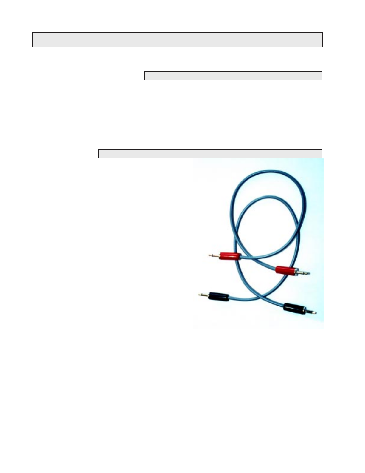
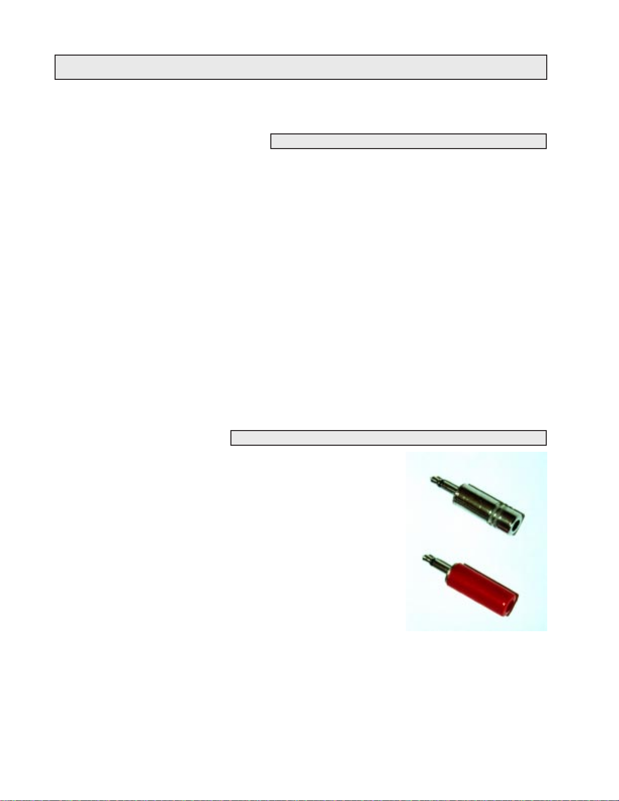
PATCH CABLES
Thin cables called patch cords or patch cables (See Figure 1-5) are used to
connect different parts of the synthesizer together. They consist of two
plugs which have been soldered to either end of a length of wire. This
wire can be of any length. Some setups offer cables of just one length,
while other setups have many different lengths of cables. The cables
ARP included with the 2600 were all of the same length, but few of
them are still around today as the wire has usually deteriorated to the
point where the cables are unreliable. Many owners of 2600’s today
either purchase cables from companies which specialize in cables or
make their own from parts acquired from electronics stores and supply houses.
Figure 1-5: Two
homemade
patch cords
Patch cables are pretty durable, but one must take care of them if they
are expected to last a long time. First, don’t ever leave them lying around
on the floor as they can be stepped on or worse yet, rolled over with a
chair. Second, whenever a patch cord is removed from a
jack in the ARP’s cabinet, pull it out by the plug rather
than by the cord. It is entirely possible to rip the cord right off of the plug if it is
pulled hard enough, because the only thing holding the two together is a drop of solder.
Third, do not bend the cable itself at tight angles, as doing so can actually sever the wire inside the
casing. Finally, when finished with them, patch cords should be stored in a safe location, away from
extreme heat and off the floor where they could become damaged. A simple hook mounted on a wall or
the side of a table is a great place to store patch cables.
Many studios use two different colors of patch cables when patching the ARP 2600; red and black. The
cables are identical other than the color of the plug and/or wire casing, and don’t function any differently, but they are used for different purposes to make it easier to understand the way the synthesizer
works. For audio signals, black cables are used. Audio signals are signals that are the raw sound that
one eventually wants to hear. Red cables are used to carry control signals. Control signals are signals
which one doesn’t intend to hear and which will be used strictly to effect change on some other part of
the synthesizer. (The difference between audio and control signals will become clearer in time.) The
next section contains a great deal more information about control signals. For now , just remember that
black is used for audio signals, and red is used for control signals.
Page 20
SECTION ONE: GENERAL CONTROLS - 005
MODULAR SYNTHESIZERS AND CONNECTIVITY
A modular synthesizer is a synthesizer that is made up of several different discreet devices which can
easily be seen and can be connected to each other in any order the user pleases. These devices are called
modules. Almost all of these modules are housed in the synthesizer’s cabinet. On the ARP 2600, it is
possible to actually see the individual modules. They are separated on the front panel of the cabinet
with heavy white lines. With larger modular synthesizers, companies often allowed users to pick and
choose which modules they wanted to make up a particular synthesizer, and as such, the modules were
entirely separate devices which didn’t share a common front panel. On a truly modular synthesizer,
these different modules are not connected to each other , and the user must connect them together using
patch cords to create sounds. This last point is very important, so keep it in mind.
The patch cords are plugged into little holes on the modules called jacks. These jacks grip the ends of
an inserted patch cord and make an electrical connection. The ARP 2600 uses 1/8 inch phono jacks (see
Figure 1-6) and as such, patch cords must have 1/8 inch phono plugs. Although they all
look the same, it is very important to understand that not all jacks are the same. Some jacks
are inputs, and some jacks are outputs. A jack which allows signals to come in is called an
input, and a jack which puts out signals is called an output. An input must be connected to
an output. Likewise, an output must be connected to an input. Connecting an input to an
input or an output to an output won’t do anything at all. This is analogous to holding the
Figure 1-6:
two 1/8”
jacks
handset of a telephone upside down. Before patching two jacks together, it is very impor tant to make sure that one of them is an input, and one of them is an output. Otherwise, the
connection being made won’t do anything.
The ARP is really a good teacher in that it is very forgiving. If a silly connection is made, such as
connecting an input to an input, or connecting an output to an output, it will not hurt the ARP at all. Just
remember: signals can only come out of an output; they can not go in. Signals can only go into an input;
they do not come out.
MODULAR: THE PROS AND CONS
There are some great advantages to modular synthesizers. First and foremost, one could connect the
modules in any order. It is possible to come up with some pretty wild combinations which are not
possible when dealing with a non-modular synthesizer (called a fixed-architecture synthesizer). Addi-
tionally, students can see each individual module and experiment with them individually, instead of
having to use them in predetermined order.
There are, of course, disadvantages to modular synthesizers as well. First, to create a sound, one must
use several patch cords. Secondly , all of the knobs and sliders must be reset for each different sound, as
most modular synthesizers can’t recall a programmer’s sounds. Most modular synthesizers also allow
the performer to play only one note at a time. Because of this, they are said to be monophonic. Many
modular synthesizers are also becoming vintage instruments (older than 25 years) at this time and are
becoming more and more unreliable. Despite all of these limitations, there is a large potential for
making interesting sounds, and wonderful music.
Page 21
006 - SECTION ONE: GENERAL CONTROLS
ARE SYNTHESIZERS NORMAL?
When sounds are created on the ARP 2600, certain modules must be connected in a certain way , and the
appropriate knobs and sliders must be set just right to produce the desired sound. This collection of
settings of patch cables, sliders, and knobs is called a patch. The term ‘patch’ comes from the patch
cables used make these sounds. Modern synthesizers don’t use patch cables, but individual sounds are
still referred to as ‘patches’.
All of this patching can be a lot of work, and many times, it is desirable to use the modules in a
standard configuration (see Section 8 for more information). It would be very time consuming and
monotonous constantly creating the same patches again and again, so the designers of the ARP 2600
came up with a good solution: normals.
What is a normal? A normal is simply a connection which is made to one of the ARP’ s input jacks from
one of the ARP’s outputs even before a patch cord is plugged into it. Another way to say this: Some
outputs are internally wired to some inputs. All but eight of the ARP 2600’s inputs have something
normalled to them. One can tell if an input has something normalled to it because there is some writing
in a small white box that points to the input. The writing indicates what is normalled to that input.
Another way to think of a normal is as a connection that is premade with an invisible patch cord. It is
not possible for a user to change what is normalled to each input.
BUT WHAT IS NORMAL?
The normal represents the patch which is most commonly used. The ARP’ s
designers made the everyday connections into normals. They didn’t nor mal modules together that one would rarely connect. Thus, it is important
to take note of which modules are normalled together, as this will give a
student some clues as to how the synthesizer will ‘normally’ be patched.
However, there are times when it is undesirable to make that particular
patch or connection which is made by a normal. This is the time when the
input jack will be used, and the normal will be broken. Breaking a normal
means disconnecting that premade electrical connection in the synthesizer . T o break a normal, all one must do is plug a patch cord into an input
jack. When a patch cord is connected to an input jack, two things actually
happen: First, the normal is broken and what was formerly connected to
that input is now disconnected. Second, whatever is traveling down that
patch cord is now connected to the input.
A great example of a normal is the headphone jack. The headphone jack is actually an output, since it
puts out a signal for headphones, but it still represents a normal. Sound is normalled from the synthesizer’s
internal amplifier to the synthesizer’s speakers. When a pair of headphones is plugged into the headphone jack, that normal is broken, and no sound can emerge from the speakers. The ARP 2600 has
thirty-nine inputs that have something normalled to them.
Figure 1-7: Nobody’s
fool. Two dummy plugs
Page 22
SECTION ONE: GENERAL CONTROLS - 007
DUMMY PLUGS
While normals are very convenient, there are times when it is desirable to break a normal without
connecting anything to that particular jack. A synthesist might want to connect a module other than the
one which is preconnected by the normal. One possible solution to this problem is to just plug one end
of a patch cord into the jack, but the problem with this is that the other end of the cord can touch objects
in the studio and create electrical noise. The cable could also pick up electromagnetic interference and
add even more unwanted noise. A dummy plug is a much better solution to this problem.
A dummy plug (see Figure 1-7 on page six) is just a plug from a patch cord without the cord. Using a
dummy plug, a normal can be broken without all of the disadvantages of plugging in one end of a patch
cord. Throughout the experiments with the ARP that follow, the reader will make use of the dummy
plug.
MODULAR VS. SEMI-MODULAR
As mentioned before, on a truly modular synthesizer, none of the modules are actually connected. Of
course, normals actually make some connections between modules without using patch cords. So it
would seem that the ARP 2600 is not actually a modular synthesizer. This is true; the ARP 2600 is not
technically a modular synthesizer. It is still possible to use it as a modular synthesizer, though, and it
retains all of the advantages of a modular synthesizer without some of the inconveniences. Because of
these subtle differences, the ARP 2600 will be referred to as a semi-modular synthesizer. Basically,
‘semi-modular’ simply means that many of the modules have normalled connections.
CLONING IN THE SYNTHESIZER WORLD
(OR: MULTIPLES AND HOW TO USE THEM)
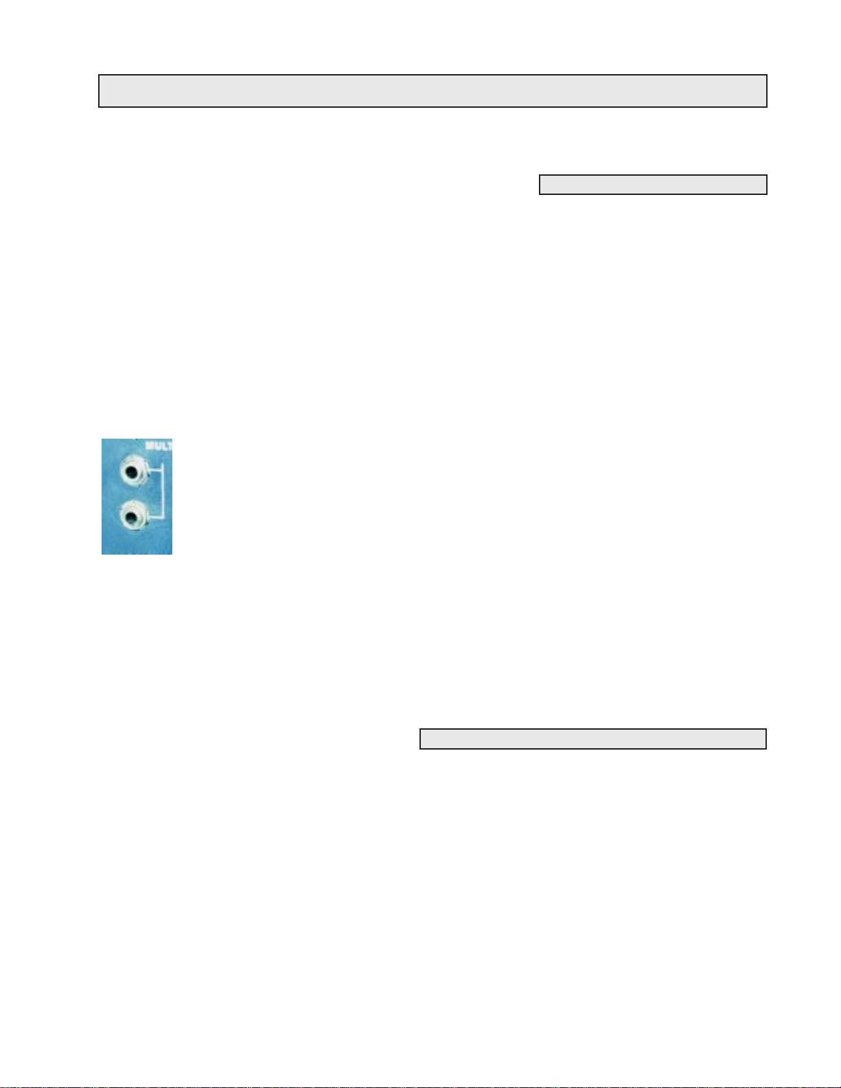
One of the first modules one will encounter on the ARP 2600 synthesizer
is the multiple. It is fairly easy to understand and use, and it really adds to
the flexibility of the synthesizer. The multiple, which is located in the
lower left hand corner of the cabinet, simply makes extra copies of any
signal. (See Figure 1-8) The multiple is made up of four jacks, which are
all wired together internally . If one connects an output to any one of those
jacks, three identical copies will come out the other jacks. This duplication occurs regardless of which jack one plugs into. Using the multiple, it
is possible to make up to three copies of a signal. This will really come in
handy later on.
Conversely , it is possible to plug three different signals into the multiple,
they will be summed, and will all be output at the remaining multiple
jack. While this is possible, it is not recommended. To properly mix sig-
Figure 1-8: The ARP
2600’s multiples
nals together, they must be passed through a device called a mixer , which
will be explored a bit more in Section 6.
Page 23
008 - SECTION ONE: GENERAL CONTROLS
CONTROL VOLTAGES AND VOLTAGE CONTROL
To make a sound, different synthesizer modules are connected together using patch cords. However,
the system that these modules use to control each other hasn’t been explained yet. Several different
systems have come and gone over time. The ARP 2600 uses one of the earliest, and most primitive. (It
is one of the easiest to understand, though!) The 2600 uses a system called voltage control to send
signals from one module to another.
In a voltage control system, modules send out a raw electrical voltage that represents a value. The
greater the voltage, the higher the value it represents. This voltage is called a contr ol voltage. The term
voltage control is used to describe a system where these control voltages are used. Synthesizers do not
use a lot of voltage to send these signals, so one is never in danger of getting an electrical shock from
the synthesizer, as long as the cabinet is not opened, which is fairly difficult to do, anyhow.
Another way to remember these two, similar sounding terms is to remember that ‘voltage control’ is
usually used as an adjective. It describes a synthesizer or a module of a synthesizer (e.g. the ARP 2600
is a voltage controlled synthesizer). Meanwhile, ‘control voltage’ is a noun. One might say that a
control voltage is being produced by a certain module.
VOLTAGE CONTROL, PARAMETERS & VALUES
Voltage control will be discussed in greater detail in the next section when it is possible to actually hear
its effects. For now, students should just try to understand the basic concept. Earlier on in this section
it was said that a parameter is something that can be changed, and the possible settings of that parameter are its possible values. On the ARP 2600, parameters are represented by control inputs. Values are
represented by control voltages. By connecting a control voltage to an input jack, that value is assigned
to whatever parameter the input jack represents. This will become clearer over time, especially when it
appears again in the next section.
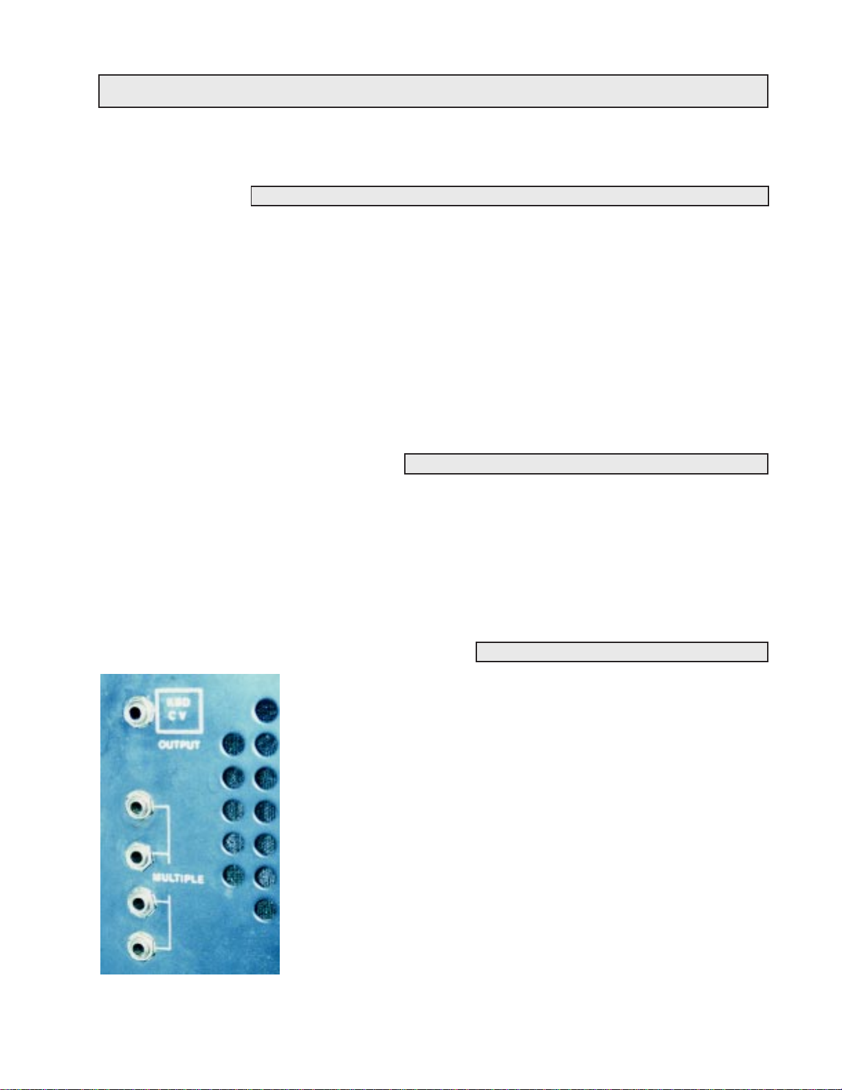
KEYBOARD CONTROL VOLTAGE
One device that creates control voltages is the keyboard. It was mentioned earlier in this section that the
keyboard receives voltage from the cabinet through its connecting cable. However, the keyboard is
also returning several signals of its own, one of which is the keyboard control voltage. The higher the
key played, the greater the voltage the keyboard sends out. This voltage goes back to the cabinet and
comes out the Keyboard CV output jack on the front panel of the cabinet. This jack is located just above
the multiple and can be seen in Figure 1-8 on page7. This voltage is then used to control the pitch of the
oscillators, as will be explained in the next section.
Page 24

SECTION ONE: GENERAL CONTROLS - 009
EXPERIMENTS FOR SECTION ONE:
1. Demonstrate left to right signal flow on the ARP’s cabinet. Why is the synthesizer designed this
way?
2. Locate the keyboard and the cabinet of the ARP 2600.
3. Locate the cable which connects the keyboard and the cabinet.
4. Demonstrate the technique for ‘zeroing’ the synthesizer and demonstrate power-up procedure.
5. Locate main power switch, the light above it, and main power cord.
6. Locate an input, and notice the symbol below it indicating its normal.
7. Locate the speakers and their volume sliders.
8. Locate the headphone jack. Demonstrate what happens to the speakers when headphones are plugged
into the headphone jack. What is this phenomenon called?
9. Demonstrate correct use and care of patch cords. Notice the colors and different lengths.
10. Demonstrate a dummy plug.
11. Locate the multiple on the front panel of the ARP.
12. Locate the keyboard control voltage output on the front panel.
Page 25

010 - SECTION ONE: GENERAL CONTROLS
REVIEW QUESTIONS FOR SECTION ONE:
1. When was the ARP 2600 made? Is this a typical production time span for a synthesizer?
2. Why is the synthesizer designed to let signals flow from left to right? What was the primary goal of
designing the ARP 2600 synthesizer?
3. Name the two main parts of the ARP 2600. Is it possible to use one part without the other? What is
one purpose of the cable that connects the two parts?
4. What must be done before the synthesizer is turned on to avoid damage to other studio devices?
5. What happens to the speakers if you plug headphones into the synthesizer? How is this a little
unusual?
6. What does ‘zeroing the synthezier’ mean? Why is it important to zero the synthesizer before using it?
7. How should patch cords be treated to protect them? Which cable generally represents which signal?
8. List the advantages and disadvantages of modular synthesizers.
9. Describe how modules are patched together.
10. What is the difference between Voltage Control and Control Voltage?
11. How does voltage control relate to parameters and values?
12. Where does the main power cable connect to the cabinet?
13. Should inputs be connected to inputs or outputs?
TERMS TO KNOW:
Monophonic
Audio Signal
Control Signal
Control Voltage
Dummy Plug
Fixed-architecture Synthesizer
Input
Jack
Keyboard Control Voltage
Modular
Module
Multiple
Normal
Output
Parameter
Patch Cable
Patch
Semi-Modular
Value
Voltage Control
Zero
Page 26
SECTION
2
VCO-1
ALL ABOUT OSCILLATORS
Oscillators are the fundamental part of any synthesizer . They are the module that creates the raw sound
that will be shaped and molded by all the other parts of the synthesizer . Oscillators function by putting
out voltage in a pattern. The faster they put out the pattern, the higher the frequency they produce.
When this output voltage is amplified and connected to a speaker, a sound can sometimes be heard.
Some people think that oscillators only put out voltage when a key is being played on the keyboard.
This really isn’t true, though. Oscillators constantly oscillate at a specified rate, even if a key isn’t being
played. Another word for rate is frequency and it is measured in Hertz (Hz).
VCO stands for voltage controlled oscillator. This means that
+10
Volts
0
time
Figure 2-1: A square wave
this module is an oscillator and can produce audio signals and
control signals. It also means that at least one of its parameters
can be controlled via voltage control. This is another perfect
example of the term ‘voltage controlled’ being used as an adjective as mentioned in Section 1.
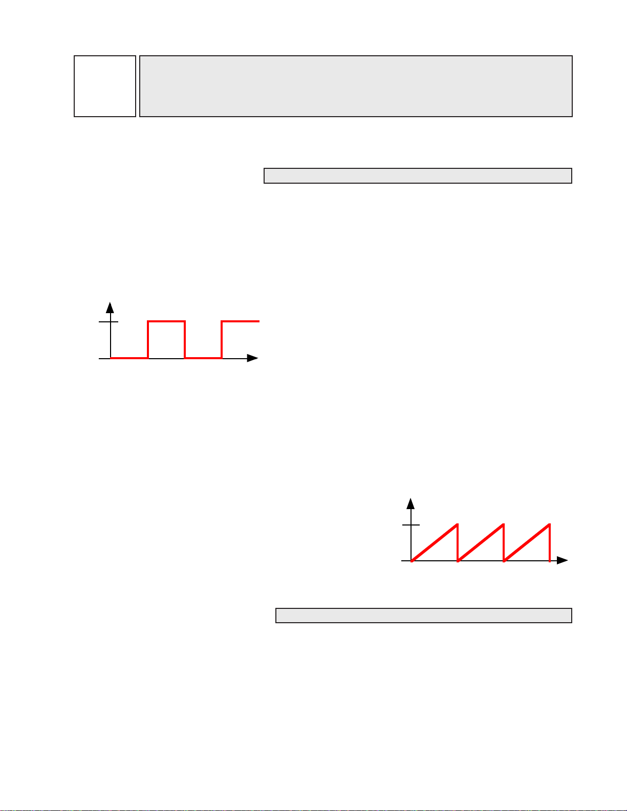
Most oscillators are capable of producing different tone colors. This is accomplished by putting out
voltage in a pattern called a waveform. For instance, to create a square wave (see Figure 2-1), the
oscillator will put out no voltage for a moment, then put out ten volts for a moment. To produce a saw
wave (see Figure 2-2), the oscillator must increase its voltage gradually to ten volts, then drop sharply
back to zero volts.
Repeating a waveform very quickly (often thousands of times
per second) produces an electronic signal which human ears
will perceive as a tone after it is amplified and is connected to
a speaker. Notice when the raw output of an oscillator is connected to a speaker that the sound is not particularly interesting
to listen to. Because the sound is static and unchanging, it is
rather monotonous or boring.
10
volts
0
time
Figure 2-2: A saw wave
THE OSCILLATOR’S TIMBRE
Oscillators have two different parameters, the first of which is timbre. T imbre comes from French, and
is pronounced tam-ber. Timbre means tone color or raw sound. When timbre changes, the shape of the
waveform changes. One can easily see by comparing Figures 2-1 and 2-2 above that a square wave
does not look anything like a saw wave. The two will sound different as well, just the way a piano
sounds different from a trumpet, even if each sounds the same note.
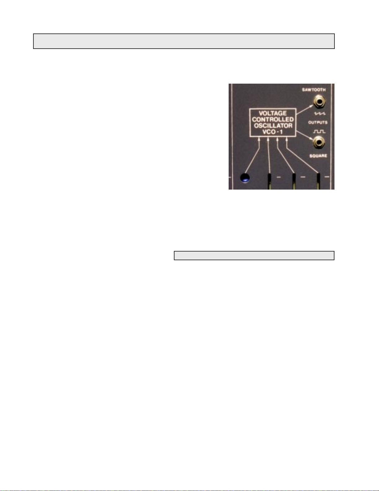
One selects a timbre by connecting a patch cord to one of the oscillator’s two outputs. In Figure 2-3,
VCO-1’s two outputs jacks can be seen. The top jack constantly puts out a saw wave and the bottom
jack puts out a square wave. It is very important to note that connecting a patch cord to one of the two
011
Page 27
012 - SECTION TWO: VCO-1
outputs is the only way the timbre can be changed. For instance,
if one wishes to hear a square wave, one must connect the square
output of VCO-1 to the speakers. The only way to change the
timbre that VCO-1 is creating is to manually connect the patch
cord to the saw output. It is important to also realize that both
outputs of an oscillator can be used at the same time so that both
timbres can be heard simultaneously.
Although everyone will perceive timbres slightly differently , it is
possible to make some generalizations about them which will
guide the student in his or her studies. The saw wave has lots of
harmonics, and as such has a sound that sounds buzzy . The square
wave, on the other hand, has only the odd harmonics, and as such,
it has a rather hollow sound. Take a moment now to listen to CD
track 01. Several tones are played by VCO-1. First, the notes are
played with a square wave produced by VCO-1. Then, the notes are played with a saw wave produced
by VCO-1. Remember to listen for the raw sound or timbre of the sound, and not how quickly or
slowly the sound begins or ends.
VCO-1’s saw and square outputs.
Figure 2-1:
THE OSCILLATOR’S FREQUENCY
The second parameter of oscillators is frequency . Frequency is often referred to as pitch by musicians.
While selecting a timbre is fairly simple, controlling frequency is a bit more involved. Frequency is
controlled in several different ways. First, VCO-1 has a coarse frequency setting. This fader can change
the oscillator’s frequency over a very large range. It is possible to make the oscillator oscillate so
quickly that it can’t be heard at all (a supersonic tone - 20 kHz or higher) or so slowly that a tone can’t
be perceived (a subsonic tone - 20 Hz or lower).
When it is necessary to tune an oscillator to another source such as another oscillator, one needs better
overall control than the coarse tuning slider can provide. This is the job of the fine tuning slider. (The
earliest version of the ARP 2600 lacked the fine tune control on VCO-1.) See page three for more
information.) The fine tuning slider increases or decreases the pitch a small amount from wherever it
has been set by the coarse tuning slider . When attempting to tune an oscillator to match another source
such as another oscillator, one should get the frequency close to that of the other source using the
coarse slider, then tune it in perfectly using the fine tuning slider.
As the oscillator’s tuning gets close to the pitch of the other source, a series of ‘beats’ can be heard.
These beats are a sort of pulsing in the sound which occur when the waveforms of the two sources
alternately cancel and reinforce each other . This results in a small change in volume which is perceived
as beats. As the frequency of the two sources gets closer and closer together, the beats will gradually
slow until finally, they stop, indicating that the two sources are perfectly in tune. Take a moment now
to listen to CD track 02. T wo oscillators are being tuned together . Listen for the slowing of the beats as
they get closer to being in tune.
Page 28

SECTION TWO: VCO-1 - 013
MODULATION: THE KEY TO THE WORLD OF SYNTHESIZERS
The third way the oscillator’s frequency is controlled is by the amount of voltage that it receives. This
is why this oscillator is called a Voltage-Controlled Oscillator; its frequency can be controlled by an
external voltage. The more voltage the oscillator is fed, the higher the frequency or pitch it will produce.
Things to this point have been pretty straightforward, but now comes the tricky part. On synthesizers,
a technique called modulation is frequently used. Modulation allows one module to change the value of
a parameter of another module. The easiest way to understand modulation is by looking at an example.
If W endy is riding in a car and she is attempting to draw a straight line across a piece of paper , she could
represent a module on a synthesizer. The line Wendy is trying to draw on the paper is the parameter
which can be changed. When the driver drives over some big bumps in the road, Wendy’s straight line
is going to be changed with each bump she rides over. So, the road is changing the value of Wendy’s
line. Instead of a nice straight line, she might end up with one that goes all over the page. What is really
happening here is that the texture of the road is modulating Wendy’s drawing.
Whenever modulation occurs, there is a carrier and a modulator. The carrier is the module whose
parameter is being changed (Wendy’s drawing in the example above). The modulator is the module
that is doing the changing (the road in the example above).
Understanding modulation is the key to understanding modular synthesis. Although modular synthesis
is called “modular synthesis” because it involves different modules, it might just as well have been
called “modular synthesis” because the individual modules change, or modulate each other. Understanding modulation is the key to understanding the ARP 2600. Once the concept of modulation is
understood, everything else becomes much more clear, and more complex patches can be attempted.
FREQUENCY MODULATION
While it is not possible to modulate the timbre of VCO-1 from another source (remember: the only way
to switch timbres on VCO-1 is to manually plug the patch cord into a different output), it is possible to
modulate the frequency using a control voltage. (This process will be dealt with in depth in the next
section.) When the frequency of an oscillator is being modulated, this technique is called frequency
modulation. Frequency modulation is often abbreviated ‘FM’.
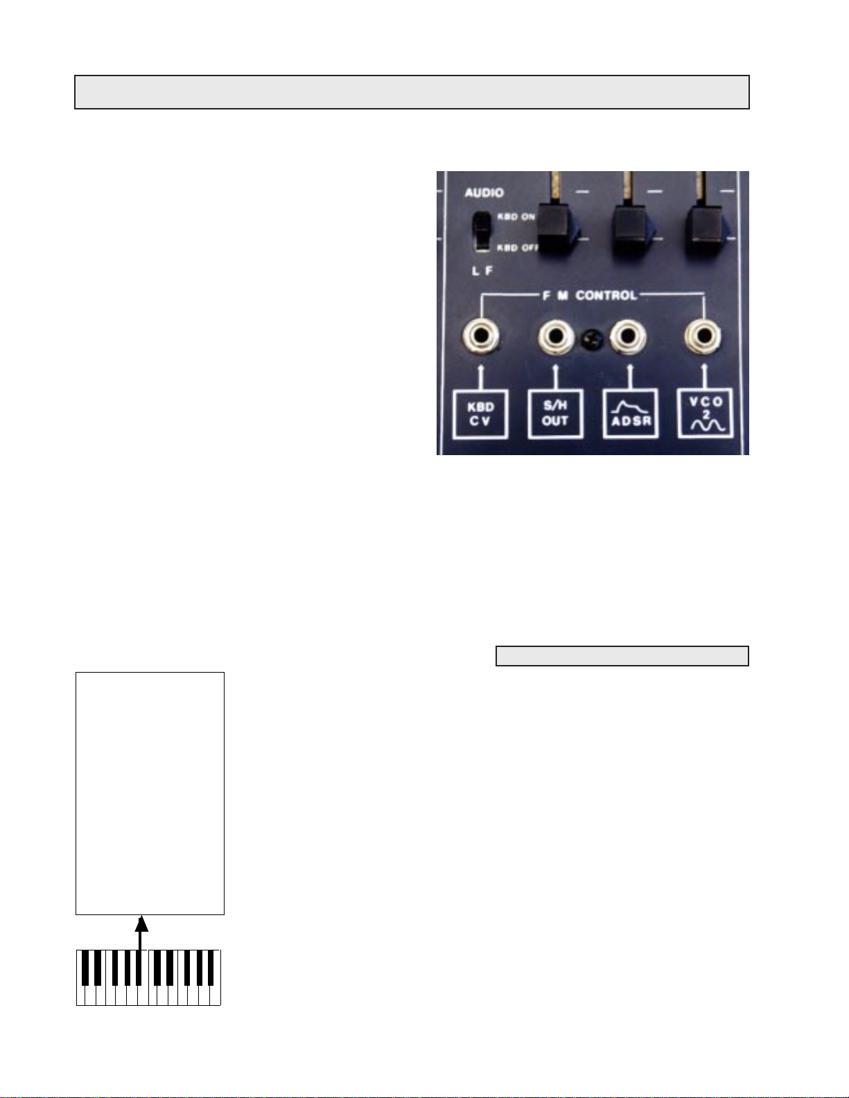
To modulate the frequency of VCO-1, a control voltage must be connected to one of the four jacks
below VCO-1. (See Figure 2-4 on page 14) These jacks are called frequency modulation inputs and
they are labeled “FM CONTROL” on the cabinet’s panel. When a control signal (like the control
voltage output of the keyboard) is connected to one of these inputs, the stage is set to modulate the
frequency of the oscillator. However, the ARP gives the user some options here. The observant student
will notice that there is something normalled to each FM input jack. These devices will all be discussed
in time. One of the most common examples of frequency modulation is a control voltage from the
keyboard modulating the frequency of an oscillator.
Page 29
014 - SECTION TWO: VCO-1
When plugging into the FM three jacks on the right of
VCO-1, the user can control the amount of control
voltage that will actually get to the oscillator. When
the slider or fader (the two terms are used interchangeably in this book) above a jack is all the way down, no
signal will be passed to the oscillator from that jack.
When the slider is all the way up, all of the incoming
control signal will be allowed to modulate the oscillator. When a fader is all the way down (or all the way
to the left) it is said to be closed. Conversely, when
the slider is set all the way up (or all the way to the
right) it is said to be open.
The left most FM CONTROL jack is normalled to the
keyboard’s control voltage. One can tell that the keyboard control voltage is normalled to this input since
the words “KBD CV” appear in the white box under the input. Since it is keyboard CV that is normalled here, it is usually desirable to have all of the keyboard control voltage modulating the frequency
of the oscillator. Thus, there is no fader above this input, and all of the incoming control signal will
always modulate the oscillator . If a fader was present above this jack, then all of the voltage would not
get to the VCO, and the keyboard would not produce chromatic half steps from one note to the next.
There is some use for this technique, and it will be explored later in this section. Frequency modulation
is the final way that Figure 2-5 below sums up all of the ways VCO-1’s frequency can be changed.
Figure 2-4: VCO-1’s FM jacks
THE KEYBOARD AND REDUNDANT PATCHES
VCO-1
VCO-1’s frequency
is determined by:
• Coarse Tune
• Fine Tune
• Control Voltage
connected to FM
inputs. (This in
cludes the key board CV normal)
Figure 2-5
The control voltage produced by the keyboard is normalled to each oscillator.
When the keyboard is played, it sends out a control voltage for each key, and
the oscillator will change its frequency depending upon how much voltage it
receives from the keyboard. This is a great example of voltage control discussed in Section 1. This is how the synthesizer is able to play different pitches
when different notes are played on the keyboard. The keyboard’s normal to the
oscillator can be broken by inserting a dummy plug into the Keyboard CV jack.
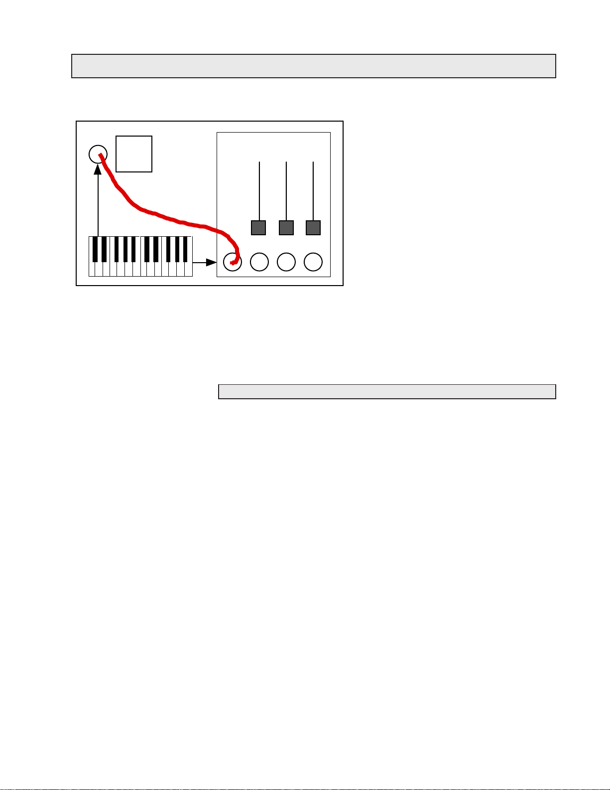
Sometimes people have trouble remembering that the keyboard’ s control voltage is normalled to the oscillators. It is possible to patch the keyboard’ s control
voltage output on the front panel to the keyboard control voltage FM input on
VCO-1, but this is not necessary , since the keyboard control voltage is already
normalled to each oscillator . Creating this patch would just be redoing what the
normal has already accomplished. If a patch is created which duplicates the
effect of a normal, it is called a redundant patch. Patching the keyboard CV
output to the keyboard CV jack on VCO-1 is a perfect example of a redundant
patch. This redundant patch is illustrated in Figure 2-6 on Page 15. (The heavy
red line represents a patch cord.)
Page 30
SECTION TWO: VCO-1 - 015
Redundant patches should be avoided for
KBD
CV
OUTPUT
Figure 2-6: A common redundant patch
sometimes go bad, and cables can pick up hum from other electrical devices and even radio waves.
Redundant patches make troubleshooting a patch much harder since they introduce so many variables.
Normals have a fairly low failure rate, and it is much better to make use of them rather than using patch
cords whenever possible.
VCO-1
FM CONTROL
several reasons. First, they use a patch cord
which could otherwise be used for some
other purpose. At first, it might seem as
though one would never actually use all of
the available patch cords in a studio at once,
but as additional synthesis techniques are discovered, experimenters will want to create
ever more complex patches which will require many patch cords. Secondly , whenever
more cables are used in an electronic music
setup, there is a greater chance for things to
go wrong. Jacks sometimes go bad, cables
LFO’S AND VCO’S
VCO-1 also leads a double life as a low frequency oscillator. By moving the Audio/LF switch (upper
left hand corner of Figure 2-4 on page 14) to the lowest position, VCO-1 will oscillate in the sub-audio
range. Sub-audio means that the pitch is so low (the frequency is so slow) that humans aren’t able to
hear a tone. Instead, a repeating series of clicks is audible. When a VCO is in low frequency mode (LF
mode for short) it is a low frequency oscillator, which is abbreviated LFO. Knowing what is now
known about frequency modulation, think about how one oscillator in LFO mode could be used to FM
another oscillator. (This is actually discussed in detail in the next section.)
As the frequency of the oscillator in low frequency mode is increased, the oscillator will eventually
reach a point where a tone can be heard. This happens around 20 Hz, or 20 cycles per second, which is
about the lowest pitch human beings can hear. Listen to CD track 03. One can hear the sound of an
oscillator in low frequency mode and its frequency is gradually being increased so that it eventually
reaches the audible range.
When a VCO is in low frequency mode, the keyboard control voltage normal is broken. This means
that the keyboard CV will no longer reach the oscillator. This is desirable because an LFO is expected
to oscillate steadily at one frequency and the keyboard CV would change the frequency at which the
LFO was oscillating. Usually, LFO’s are used to create vibrato, which will be discussed in the next
section. For the rare occasions when a synthesist wants an LFO’s frequency to follow the keyboard CV,
the synthesist can use a patch cord to connect the keyboard CV output jack to one of the FM input jacks
on the oscillator. The label to the right of the LF switch reminds the user that the keyboard will be
disconnected when the switch is set to the low position. It says “KBD ON” near the audio position, and
“KBD OFF” near the LF position.
Page 31

016 - SECTION TWO: VCO-1
EXPERIMENTS FOR SECTION TWO:
1. Listen to the raw sawtooth output by patching oscillator directly to an input on the mixer (your
teacher can help you with this). Describe the timbre.
2. Listen to raw square output by patching oscillator directly to an input on the mixer. Describe the
timbre. CD track 01
3. How else can the timbre the VCO is producing be changed without moving the patch cord?
4. Patch both wave outputs into the mixer. Is it possible to hear both timbres at once?
5. Control the frequency of VCO-1 by moving the INITIAL FREQUENCY slider . T ry to play a simple
song. Is this and effective way to control the frequency of an oscillator? Now control the pitch
using the FINE TUNE slider.
6. While listening to either output of VCO-1, play the keyboard and notice that VCO-1’ s pitch changes.
What is occurring here?
7. Create a redundant patch by connecting the keyboard’s CV output to the FM input labeled “KYBD
CV”. Notice that this has the same effect as the normal in experiment #6.
8. Insert a dummy plug into the FM control input labeled “KYBD CV” on VCO-1 and play the keyboard. What is occurring now?
9. Put VCO-1 in LF mode using the Audio/LF switch. Lower the initial frequency slider so that it is
open only about 1/4. What sounds do you hear when listening to the saw wave? When listening
to the square wave?
10. After conducting experiment #9, try playing the keyboard. What happens and why?
11. Starting in the sub-audio range (LF mode), slowly bring VCO-1’s frequency into the audio range.
Notice the point at which one can first hear a tone. CD track 03
12. Zero VCO-1, then practice frequency modulation on VCO-1 by using a dummy plug to break the
keyboard CV normal on the left most FM input. Then patch the Keyboard CV output to one of
the other FM inputs and fully open the slider above that jack. How is this not as desirable as
using the normal from the keyboard CV? What happens if you set the slider in a position other
than fully open or fully closed? What is noticeable about the pitch even when the slider is fully
open?
13. How many notes can VCO-1 produce at one time?
Page 32

SECTION TWO: VCO-1 - 017
REVIEW QUESTIONS FOR SECTION TWO:
1. Describe an oscillator’s function and role in the synthesizer, and tell how it works.
2. Explain when oscillators oscillate, and tell why the raw sound they produce is rather boring.
3. Name the oscillator’s two parameters, and the way both can be changed from the oscillator itself.
4. Tell how many different waveform outputs can be used at once from VCO-1.
5. List the three things that determine a VCO’s pitch.
6. Describe the timbre of saw and square waves.
7. Describe the best way to tune VCO-1 to another source.
8. Describe how the keyboard is connected to VCO-1.
9. List three reasons why it is highly desirable to avoid redundant patches.
10. Give an example of modulation. Be sure to include the words carrier and modulator in your explanation. Tell why it is so important to understand modulation.
11. Give an example of frequency modulation. Also, describe what connections must be made to frequency modulate an oscillator.
12. Speculate how an LFO will be useful later. Tell how to put a VCO into LF mode. Describe what
happens to the keyboard CV normal to VCO-1 when VCO-1 is put into LF mode.
13. How many FM control inputs does VCO-1 have?
TERMS TO KNOW:
Carrier
Closed
Fader
Frequency
Frequency Modulation
Frequency Modulation Inputs
Hertz
LF Mode
LFO
Modulation
Modulator
Open
Oscillator
Pitch
Redundant Patch
Sawtooth Wave
Slider
Square Wave
Subsonic
Supersonic
Timbre
VCO
Waveform
Page 33

SECTION
3
VCO-2
A FIRST LOOK
In Section 2, a basic voltage controlled oscillator (VCO-1) was discussed in detail. In this section,
VCO-2 will be examined. Although VCO-2 is more complex than VCO-1, all of the things that were
said about VCO-1 apply to VCO-2. VCO-2 can be thought of as the ‘super oscillator’ on the ARP 2600
since it is the most flexible, and thus the most powerful oscillator of the three found on the 2600. The
first thing one notices when looking at VCO-2 for the first time is the additional waveforms that
VCO-2 can produce. In addition to the saw wave, VCO-2 can produce sine, triangle, and pulse waves.
SINE WAVES
Sine waves (see Figure 3-1) have a very pure sound, because they have only one harmonic, and that is the fundamental. CD track 07 It is also important to note that while
the square and saw waves that VCO-1 produced ranged between 0 Volts and +10 Volts, the sine wave VCO-2 produces
ranges between -5 Volts and +5 Volts. Overall, it still has the
same amplitude span as the waveforms VCO-1 produced,
but because it dips into negative voltage, it is more flexible.
When the sine wave output is used to modulate another
source, it can actually send a negative value to that carrier,
rather than just a positive value. This technique will be explored in depth in a later section.
+10V
+5V
0V
-5V
-10V
time
Figure 3-1: A sine wave
TRIANGLE WAVES
Triangle waves (see Figure 3-2) sound a little buzzy, but
smoother than a saw wave. Although they look very similar
+10V
+5V
0V
-5V
-10V
Figure 3-2: A triangle wave
wave. It is also important to note that like the sine wave, the triangle wave ranges from -5 Volts to +5
Volts, meaning that it can send a negative value to a carrier when it is being used as a modulator.
time
018
to a saw wave, they are actually most like square waves harmonically . CD track 07 Just like the square wave, they have
only the odd numbered harmonics. At first, this doesn’ t seem
to make any sense. If the harmonic content of a waveform
determines its shape, and the triangle and square waves both
have the same harmonics, shouldn’t they look alike and sound
alike? Actually, it is possible for two different waveforms to
have the same harmonics present, but present in different
amounts. In the triangle wave, some of the upper harmonics
are present in higher amounts than in the square wave. This
gives it a buzzy sound which is different from the square
Page 34

SECTION THREE: VCO-2 - 019
NOT JUST ANOTHER PRETTY PHASE
When two waveforms begin and end together, they are said to
be in phase with each other. In Figure 3-3, one can see that the
two sine waves shown are in phase with each other. (The two
overlapping sine waves are represented by the thick red line.)
When two identical waveforms are in phase with each other, an
interesting thing happens. They are summed, and the result that
humans hear is louder than the amplitude of either of the waveforms alone. This phenomenon is called reinforcement. In Fig-
ure 3-3, the taller black line shows the result of the two red sine
waves being summed.
A waveform’s cycle can be measured in 360 degrees like a circle.
In Figure 3-4, some of the important phase angle marks are
indicated. When one waveform starts halfway though the cycle
Figure 3-3: Reinforcement
of another waveform, the two are said to be 180 degrees out of phase, since half of 360 is 180. Similarly, if one waveform starts a quarter way through another waveform’s cycle, the two would be 90
degrees out of phase. This measurement is called the phase angle. When two waveforms are 180
degrees out of phase with each other, and the waveforms are identical, a strange phenomenon occurs.
Because the crest of one wave occurs at the same time as the trough of another, the two cancel each
other out, and the listener perceives a reduction in volume. This phenomenon is called cancellation. In
the real world, it is very difficult to get two waveforms to cancel each other out completely , even under
carefully controlled circumstances.
time
PHASE RELATIONSHIPS
The triangle and sine outputs of VCO-2 have an important quality: They are 180 degrees out of phase
with each other. In Figure 3-4, one can see that the triangle wave (green) reaches its highest amplitude
at 90 degrees, just when the sine wave is at its
lowest amplitude. However, if the triangle and
sine waves are added together, they will not cancel each other out. Remember that the two have
different waveforms, and a different harmonic content. The sine wave has only the fundamental, and
as such, it will only cause cancellation of the triangle wave’s fundamental.
The phase relationship between the triangle and
the sine outputs is the most obvious and easiest to
observe. However, when dealing with simple
waveforms like the ones the ARP 2600 can produce, it is possible to say that two waveforms are
180 degrees out of phase when the highest point
0 90 180 270 0 90
Figure 3-4: The sine and triangle
waves are 180 degrees out of phase
180 270
time
phase angle
0
Page 35

020 - SECTION THREE: VCO-2
of one waveform occurs at the lowest point of another. The
phase relationships of the other outputs can be easily summed
up: outputs which are perpendicular to each other (i.e. above
below, or to one side) are 180 degrees out of phase. Those
diagonal to each other are in phase. Figure 3-5 illustrates this
relationship. Red arrows represent out of phase relationships
while blue and green arrows represent in phase relationships.
Triangle
out of
phase
out of
phase
in phase
Sawtooth
out of
phase
PULSE WAVES
out of
phase
VCO-2 doesn’t really have a square wave output, but has a
pulse wave output instead. This is a very important feature
Sine
Pulse
since a pulse wave is like a square wave, but is much more
flexible. Pulse waves, like a square wave, are partially “on”
and partially “off.” In terms of voltage, a pulse wave con-
Figure 3-5: The phase
relationships of VCO-2’s outputs
sists of ten volts for a moment, then zero volts for a moment. For a square wave, these two ‘moments’
must be equal. In a pulse wave, they can be equal, but do not have to be equal. Thus, a square wave is
really just a kind of pulse wave.
PULSE WIDTH
One important aspect of a pulse wave is that it is another parameter to change. That parameter is the
pulse width. Of course, in Section 2, the reader learned that there are only two parameters of an
oscillator one can change: frequency and timbre. One might think of pulse width as a sort of
subheading under the ‘timbre’ parameter heading.
Pulse width is the name of the parameter that controls how much of the
wave is ‘on’ and how much of the wave is ‘off.’ Another name for pulse
width is duty cycle. The duty cycle of a pulse wave is expressed as a per-
30% duty cycle
50% duty cycle
Figure 3-6: Pulse waves with
different duty cucles
time
time
centage. The percentage tells how much of the duty cycle is ‘on.’ For instance, a pulse wave that has a pulse width of 20% would be a pulse wave
which is ‘on’ 20% on the time, and ‘off’ 80% of the time. Figure 3-6 illustrates a pulse width of 30%, and a pulse width of 50% (a square wave).
Making changes in the pulse width changes the waveshape and thus the
timbre. This is why it is difficult to describe the pulse wave’s timbre: the
timbre changes significantly when the pulse width is changed. The timbre
can range from hollow when the duty cycle is near 50% to nasal when it is
nearer 0% or 100%.
On the 2600, changing VCO-2’s pulse width is simple. The pulse width is
changed by moving the PULSE WIDTH slider, right under the FINE TUNE
slider. This control can be seen, along with VCO-2’s outputs and initial
frequency controls in Figure 3-7 on page 21. When the pulse width is set to
50%, the VCO will produce a square wave (if it is properly calibrated).
Page 36

SECTION THREE: VCO-2 - 021
A NOTE ABOUT CALIBRATION: Throughout this text, the reader will see phrases such as “if
it is properly calibrated.” One may begin to wonder how calibration is achieved. Once again,
different versions of the 2600 have slightly different methods of calibration. In most cases,
there are small holes in the front of the cabinet, each of which has a trim pot inside. One such
hole can be seen in Figure 3-7. By inserting a standard screwdriver, one can turn the trim pot
and calibrate each module. On the first models produced (the “Blue Meanies,”) each calibration hole was actually labeled with the function it calibrated. While this was highly userfriendly , it seems that it was also highly inviting, and many people managed to get their 2600’ s
out of whack before they were really familiar with them. By the time ARP made the grey faced
2600’s, the labels had disappeared, and some of the less frequently used calibrations (such as
the high frequency tracking on the VCO’s) were moved inside the cabinet.
In any case, the calibration procedure was not one that ARP kept secret. In fact, the procedure
can be found near the back of the 2600 manual. It is fairly easy to perform, and does not
require any equipment other than a screwdriver and a good ear. It helps to have something to
reference when calibrating the range of the oscillators, such as a tuning fork, but it is really not
necessary. However, the 2600 rarely requires calibration, and when it does, it is truly as the
manual states, “calibration without tears.”
Notice that the label on the pulse width control only extends from
10% to 90%. This is because when the pulse width becomes too narrow , no sound can be heard. Another important fact to note is that the
human ear cannot perceive the difference between a 10% duty cycle
and a 90% duty cycle. Similarly , one can’ t tell a 40% duty cycle from
a 60%, a 32% from a 68% and so on. This is because a 10% duty cycle
is just the same as an inverted 90% duty cycle, and without a reference, the ear can’t hear when a waveform has been inverted. Because
of this phenomenon, some synthesizer manufacturers produce synthesizers whose pulse width is only variable from 10% to 50%, since
sweeping the pulse width from 10% to 90% sounds the same as sweeping the pulse width from 10% to 50% and back to 10% again. Because
of this phenomenon, some manufacturers decide to leave the pulse
width control without any labels other than “pulse width.”
Figure 3-7: VCO-2’s controls
MORE ABOUT FREQUENCY MODULATION
In Section 2, the concept of frequency modulation was introduced. Frequency modulation occurs when
a control voltage is used to change the frequency of an oscillator. The only frequency modulation that
could be observed when the concept was introduced was the keyboard modulating the frequency of
VCO-1. Now , however it is time to apply some of the knowledge collected in the first two sections and
attempt some more complicated frequency modulation.
Page 37

022 - SECTION THREE: VCO-2
CREATING THE FIRST FM PATCH
VCO-2, like VCO-1, can be made into an LFO by switching the LF switch. In the example which
follows, VCO-2 is used in LF mode to modulate the frequency of VCO-1. First, it is important to
determine the relationship of the two VCO’s. Recall that when modulation occurs, there must be a
carrier and a modulator . VCO-1 is the carrier , so it will produce sound so that the frequency modulation
can be heard. VCO-1 must be patched to the mixer so that it can be heard. Its frequency must be set in
roughly the middle of its range so that it is easy to hear the effect of the modulator on it. If the frequency
is set too high or too low, FM’ing it may push it into the supersonic range or subsonic range respectively , and then the results of the experiment cannot be heard. VCO-1 will be modulated by VCO-2, so
VCO-2 is the modulator, and it will produce the control voltage which will be modulating VCO-1.
One of VCO-2’s outputs must be connected to VCO-1 so that VCO-2 can modulate VCO-1. After
switching VCO-2 to LF mode, the saw output can be connected or patched to one of the FM inputs on
VCO-1. Recall from Section 2 that these FM inputs accept incoming control voltages and the more
voltage they receive, the higher the pitch the oscillator produces. Finally , the fader above the FM input
on VCO-1 must be raised to allow some of the incoming control voltage to modulate VCO-1’s fre-
quency . Figure 3-8 depicts this patch.
VCO-2
In LF Mode
Saw W ave
Output
Figure 3-8: A basic FM patch
to build a mental list of different simple patches and how each one works. It will soon become clear that
even the most complex patches are really just a collection of very simple patches all used at the same
time. For instance, four or five frequency modulations similar to the one shown above might occur
simultaneously. That would produce some complex results indeed!
VCO-1
Saw Wave
Output
FM input
To amplifier
and speakers
Being able to look at a
block diagram of a
sound or reading about
a patch and being able
to predict how it will
sound is a very important skill; important
enough that it is the
subject of Section 14.
It is important to begin
DISSECTING THE BASIC FM PATCH
In Figure 3-8, VCO-2 is putting out a saw wave slowly because it is in LF mode. This saw wave is
connected to an FM input on VCO-1 using a patch cord. VCO-1’s frequency will change with the
incoming saw wave from VCO-2. As the saw wave from VCO-2 slowly goes up, the frequency of
VCO-1 will go up as well. When VCO-2’ s saw wave suddenly drops low to begin again, the frequency
of VCO-1 will also drop suddenly to begin rising again. This patch can be heard by listening to CD
track 04. Listen as VCO-2’ s waveform is changed. Is it possible to determine which waveform is being
used just by listening to the results?
Page 38

SECTION THREE: VCO-2 - 023
This is also the first really clear
THE BLACK ART OF PATCH DIAGRAMMING
Patch diagramming and analysis will be explored in depth in
Section 14, but there are some important aspects of patch diagrams which must be explored now . The following conventions
are used in this book: First, control signals are drawn with red
lines while audio signals are drawn with black lines, just as red
patch cords are used for control signals and black cords for audio signals. Second, carriers are indicated with a blue background
while modulators are indicated with a green background. Finally, audio signals exit each module to one side while control
signals exit and enter modules from the bottom or top. The only
notable exception to this last convention is the audio connection of signals to the amplifier and speakers. T o conserve space,
the connection is always drawn below the words indicating the
speakers and amplifier. Each of these conventions can be seen
in Figure 3-8 on page 22.
is strictly incorrect. The signal from VCO-2 just changes or modulates a parameter of VCO-1, but
doesn’t pass through it. However , VCO-1’ s output is an audio signal. The intent is that VCO-1’ s output
will be heard, which is part of the definition of an audio signal.
example of a patch which uses
control and audio signals. VCO2’s output going to VCO-1 is a
control signal. It is a control signal because it is never heard, nor
is it intended to be heard. One
can tell that it is a control signal
because it is a sub-audio signal
(VCO-2 is in LF mode) and the
signal emerges from the bottom
of the module in Figure 3-8, and
it is drawn with a red line. (See
the sidebar “The Black Art of
Patch Diagramming” for more
information.)
Don’t think that VCO-2’s output passes through VCO-1. This
THE PARAMETERS OF A BASIC FM PATCH
There are several different parameters available to the reader in this patch. The first parameter is the
starting pitch of VCO-1. Of course, the pitch or frequency is going to be changed through frequency
modulation, but one must set a starting frequency using the INITIAL FREQUENCY slider to establish
the range in which VCO-1 will move.
The second parameter is the waveform that VCO-1 is producing. This determines the timbre of the
final sound. Either the saw wave or the square wave could be chosen. While it is important to understand that this parameter can be changed, it is not particularly important to the discussion at hand.
The third parameter one can change is the amount of control voltage VCO-1 is receiving from VCO-2.
This parameter is referred to as depth or modulation depth. There are sliders above each of the FM
inputs on VCO-1, and these determine how much control signal is allowed through to modulate VCO-
1. The higher the slider is set, the greater the depth of modulation, and the more control voltage will
modulate VCO-1. Essentially, the slider ‘turns down’ the amount of control signal getting to VCO-1
when the slider is moved down. The term used to describe this ‘turning down’ is attenuation.
The fourth parameter in this patch is the waveform that VCO-2 is producing. VCO-2 can produce four
different waveforms, but the pulse width can be changed on the pulse wave, so that allows hundreds, if
Page 39

024 - SECTION THREE: VCO-2
not thousands more possibilities. Selecting a different waveform for VCO-2 means that the frequency
of VCO-1 will be modulated in a different pattern. While choosing a sine wave would produce a
smooth rising and falling of tone, a triangle wave would produce a slightly more pronounced change in
direction of the rising and falling of frequency . A saw wave would cause the frequency to ramp slowly
up, then drop off. A pulse wave would cause the frequency to alternate between two specific pitches.
A possible fifth parameter for the patch given above is pulse width. Of course, this only applies when
the pulse wave is being used for frequency modulation. The pulse width would determine how much of
the control signal would be high and how much would be low, and thus, how much of VCO-1’s frequency would be high and how much of VCO-1’s frequency would be low.
The sixth parameter in this patch is VCO-2’s frequency. This parameter also has a special name; it is
referred to as rate or modulation rate. The faster VCO-2 oscillates, the greater the rate, and the faster
VCO-1’s frequency will change. As the frequency is gradually increased, the frequency begins to change
so fast that human ears can no longer perceive the change. This happens when VCO-2 is oscillating so
fast that it is actually in the audio range (i.e. 20 Hz or higher), and the depth is great enough (see the
third parameter). When both the depth and the rate are great enough, a strange phenomenon occurs.
SIDEBANDS
When both the depth and the rate are great enough, harmonics are added to the timbre VCO-1 is
producing. These harmonics are called sidebands. An example of sidebands can be heard by listening
CD track 05. Sidebands suddenly decrease if the carrier and modulator’s frequencies are multiples of
each other. For instance, if VCO-1 is tuned to 440 Hz and VCO-2 is tuned to 220 Hz, there will be
fewer sidebands since 220 x 2 = 440. To summarize: Sidebands are produced when frequency modulation is occurring, the modulator is in the audio range, the modulation is deep enough, and the carrier
and modulator’s frequencies are not multiples of each other.
Some people spend hours mathematically calculating exactly what frequencies will be added as the
sidebands form. (This can be calculated through a complex series of formulas which take into account
the carrier’s waveform, the modulator’s waveform, exactly how loud each of the waveform’ s hundreds
of harmonics are and the overall frequency of the carrier and modulator.) They can create charts and
graphs showing the frequency content of the new sound, but this is really rather impractical for the
purposes of this book. This analytical branch of electronic music will be ignored for the time being as
it falls too far outside the practical application of music technology. It is merely important to understand that it is possible to mathematically predict which sidebands will occur.
SUMMING UP THE PATCH
To summarize, in the basic frequency modulation patch, there are five (sometimes six) parameters.
Each of these is labeled in Figure 3-9, which depicts the front panel of the instrument rather than a
patch diagram.
Page 40

SECTION THREE: VCO-2 - 025
1. VCO-1’s starting frequency
2. VCO-1’ s timbre
3. Modulation depth
4. VCO-2’ s waveform
5. Pulse width of VCO-2
(if using the pulse wave
for modulating VCO-1)
6. Modulation rate
Frequency modulation is used all the time
in music technology. The most common
application of FM is vibrato. Vibrato is a
very slight rising and falling of the pitch
of a sound. It is this slight rising and falling that makes a sound more human and
eliminates the sterile qualities of the raw
waveforms.
PULSE WIDTH MODULATION
In addition to modulating frequency with a control voltage, it is also
possible to use a control voltage to modulate the duty cycle or pulse
width of the pulse wave. Because the pulse width is being modulated,
this kind of modulation is called Pulse Width Modulation or PWM.
Pulse width modulation has a distinctive sound which must be heard
to be understood. Listen to CD track 06 which demonstrates the patch
shown in Figure 3-11 on page 26. PWM provides a wonderful way to
create timbres which change continuously in time, holding a listener’s
attention.
INITIAL OSCILLATOR FREQUENCY
10 100 1KHz 10KHz
.03 .3 3.0 30
FINE TUNE
1
SAWTOOTH
VOLTAGE
CONTROLLED
OSCILLATOR
VCO-1
2
3
AUDIO
KBD ON
KBD OFF
L F
FM CONTROL
S/H
KBD
OUT
CV
ADSR
OUTPUTS
SQUARE
VCO
2
INITIAL OSCILLATOR FREQUENCY
10 100 1KHz 10KHz
.03 .3 3.0 30
FINE TUNE
PULSE WIDTH
10% 50% 90%
5
VOLTAGE
CONTROLLED
OSCILLATOR
VCO-2
AUDIO
KBD ON
KBD OFF
L F
FM CONTROL
S/H
KBD
OUT
CV
ADSR
6
TRIANGLE
OUTPUTS
SINE
VCO
1
SAWTOOTH
4
PULSE
PWM
PULSE WIDTH
MODULATION
NOISE
GEN
LEFT
INPUT
VCF
LEFT
OUTPUT
MIXER
AUDIO
RIGHT
OUTPUT
PAN
RIGHT
INPUT
REVERBERATOR
REVERB
OUTPUT
MIXER
VCA
OUT
Sometimes, if a synthesizer is out of calibration, the oscillator will
stop sounding momentarily because the pulse width becomes so narrow or so wide that the oscillator no longer produces an audible sound.
T o prevent this from happening, the PULSE WIDTH slider should be
set far enough left so that the pulse width never gets narrow enough to
Figure 3-10: VCO-2’s
FM and PWM inputs
stop sounding.
Notice in Figure 3-10 that VCO-2 has an extra input located just to
the right of the FM inputs. This is the PWM input. It has its own slider to attenuate the incoming control
voltage. A control voltage input here will cause the pulse width to change continuously over time.
When a parameter changes continuously over its entire range of values, it is said that the parameter is
swept. A pulse width sweep can be created by setting VCO-1 to LF mode, and connecting its saw wave
output to VCO-2’ s PWM input. Be sure that VCO-2 is in audio mode, and that VCO-1 is not oscillating
too quickly. This patch is diagrammed in Figure 3-11 on page 26.
Page 41

026 - SECTION THREE: VCO-2
In this patch, VCO-1 is the
modulator, and VCO-2 is the
VCO-1
In LF Mode
Saw Wave
To amplifier
VCO-2
Pulse
W ave
Output
PWM input
Figure 3-11: A basic PWM patch
carrier . The saw signal going
from VCO-1 to VCO-2 is a
control signal, while the pulse
wave output of VCO-2 is the
carrier signal. Pulse width
modulation has a very distinctive sound and while it is not
widely used, it is certainly an
important and useful synthesis technique.
DISSECTING THE BASIC PWM PATCH
The basic PWM patch has only four parameters. First, the frequency of VCO-1 can be set. This parameter is once again referred to as rate in this patch. Secondly, VCO-1’s waveform can be changed.
However, the saw wave is really a more common choice than the square wave, since the saw wave will
produce a continuous sweep. Third, the incoming control voltage can be attenuated by the fader above
the PWM input. This parameter will once again be referred to as depth. When too much depth is used
in PWM, it becomes hard to perceive a tone. When the depth and rate become fast enough, once again,
sidebands are produced. These sidebands are very similar in sound to those created by FM. Finally,
VCO-2’s frequency can be set. VCO-2’s timbre is not a parameter in this patch, since it is not something that can be changed. If one wants to hear PWM, one must use a pulse wave.
OTHER POSSIBILITIES WITH TWO OSCILLATORS
Another useful technique available to the experimenter at this time is using both VCO-1 and VCO-2 in
audio mode, and listening to different waveforms from each of them at the same time. Patching the
square output of VCO-1 and the saw output of VCO-2 to the mixer might sound pretty unpleasant at
first, but this is merely because the oscillators haven’t been tuned together.
In Section 2, the technique for tuning an oscillator to another source was discussed. Now is the time to
apply that knowledge. It is important to first decide which oscillator will be the one that will be tuned
and which oscillator will be the one that the other is tuned to. For demonstration purposes, VCO-1 will
be the standard by which to tune VCO-2 and that VCO-2 will be the oscillator that will actually be
tuned.
To begin, VCO-1 must be set at a comfortable frequency. Next, VCO-2’s frequency must be roughly
matched to VCO-1’ s. This is accomplished with the INITIAL FREQUENCY slider . It takes a good ear
and a steady hand to accomplish this. Once VCO-2 is close to VCO-1, the FINE TUNE slider is used to
bring them exactly in tune. As the frequencies get close to matching, ‘beats’ can be heard in the sound.
These beats can be a big clue to how close the frequencies are to matching each other. The faster the
beats, the farther the frequencies are from matching. If the FINE TUNE slider is being moved, and the
Page 42

SECTION THREE: VCO-2 - 027
beats are speeding up, then the frequencies are getting farther apart, and the slider is being moved the
wrong direction. Eventually , if the slider is moved in the correct direction and the coarse tuning slider
was set close to begin with, the beats will slow to an almost imperceptible speed. The oscillators are
then in tune.
PHAT TUNING
It is not always desirable to put the oscillators perfectly in tune, however. Many pop songs today use
oscillators which are intentionally out of tune as this yields a wider, warmer sound that analog synthesizers like the ARP 2600 are known for. The term for this detuned sound is taken from urban hip-hop
culture and is mutated from an English word. The word is phat and is pronounced just like ‘fat.’ This
sound is the reason that old analog synthesizers like the ARP 2600 are highly sought after and are
prized by synthesists everywhere. CD track 11
Herein is the big advantage of using two oscillators to create a square and saw wave as opposed to
using one oscillator to create the same waveforms. Indeed, the more oscillators used to make a sound,
the warmer, thicker, and more interesting the sound will be.
Another great possibility available to the student at this time is tuning the oscillators in different
intervals. Great sounds can be achieved by tuning the oscillators in octaves, perfect fifths, and perfect
fourths. Of course, there are lots of other interesting possibilities, and the general rule is that if a patch
sounds good, then it is acceptable. Tuning in different intervals, combined with the phat tuning
discussed earlier will yield some great new sounds.
Page 43

028 - SECTION THREE: VCO-2
EXPERIMENTS FOR SECTION THREE:
1. Listen to raw saw , square, sine and pulse outputs by patching each directly to the mixer . Describe the
differences in timbre. Notice which waves seem softer. CD track 07
2. Experiment with the INITIAL FREQUENCY slider, and FINE TUNE sliders.
3. While listening to the pulse wave, trying varying the PULSE WIDTH using the pulse width slider.
Try to duplicate the sound of a square wave perfectly. CD track 08
4. Create the FM patch given in this section, and experiment with each of the five or six parameters. Do
not stop until all of the possibilities have been exhausted. Have patience and try all of the
possibilities. This is not a quick procedure. It is important to constantly ask the following
questions:
1. How does this set of parameter values sound?
2. Why does it sound like this?
3. What exactly is happening between these two oscillators?
It is also important to take notes on the results so that other patches that will be illustrated later
can be better understood. CD track 09
5. Using a square wave from VCO-2 in LFO mode, produce leaps of different intervals in VCO-1 using FM. How does it sound to use octaves or tritones? Can the sound of a French Ambulance
siren be generated? CD track 10
6. Using a ramp wave or the triangle wave, create a ‘siren’ type of sound. CD track 10
7. Slowly increase the frequency of the LFO until sidebands appear. Why do the sidebands seem to
disappear at certain frequencies? CD track 05
8. Create the pulse width modulation patch given in this section, and once again, experiment with all
of the available parameters. Note the different sounds that can be created. CD track 06
9. Patch the square output of VCO-1 to the mixer and the saw output of VCO-2 to the mixer. Practice
tuning them together using the tuning technique given in this section. Also try tuning in different intervals.
10. Detune VCO-1 and VCO-2 to create the phat tuning. CD track 11
11. Combine the triangle and sine outputs of VCO-2 in the mixer. While listening to the triangle output,
slowly raise the volume of the sine output. Is it possible to hear the fundamental being cancelled?
Page 44

SECTION THREE: VCO-2 - 029
REVIEW QUESTIONS FOR SECTION THREE:
1. Compare and contrast VCO-1 and VCO-2.
2. Describe the timbre of the sine, saw and square waves, and tell why it is difficult to describe the
timbre of the pulse wave.
3. Explain how duty cycles are expressed numerically, and why human ears can’t tell the difference
between 10% and 90%. Describe the relationship of square and pulse waves.
4. Name the six parameters of a basic frequency modulation patch and describe what effect changing
the value of each has on the resulting sound. Draw a simple diagram of the patch.
5. Why is vibrato musically useful?
6. Tell which outputs are in phase with each other, and which outputs are out of phase with each other .
7. How did calibration change as the ARP 2600 evolved?
8. Draw a simple diagram of a PWM patch.
9. Describe the technique used for tuning two oscillators together and define and describe the phat
tuning technique.
10. State why it is desirable to use two different oscillators to produce two waveforms.
11. Tell what is meant by ‘tuning in intervals’ and state why this is a highly useful technique.
12. Discuss the voltage ranges of the triangle, sine, and pulse waves produced by VCO-2.
TERMS TO KNOW:
Attenuation
Cancellation
Duty Cycle
Modulation Depth
Modulation Rate
Phase
Phase Angle
Phat Tuning
Pulse Wave
Pulse Width
Pulse Width Modulation
PWM
Reinforcement
Sidebands
Sine Wave
Sweep
Triangle Wave
V ibrato
Page 45

SECTION
4
VCO-3
HELLO AGAIN!
VCO-3 is very similar to VCO-1. In Figure 4-1, it is easy to see how similar the
two really are. It can only produce two different waveforms: saw and pulse
waves. However, it lacks the PWM input that VCO-2 is blessed with, so PWM
is not possible. It is somewhat more flexible than VCO-1, though, because VCO1 can only produce a square wave. VCO-3 can create a pulse wave, which
becomes a square wave when the pulse width is set to 50% and can also produce many other timbres as well. Other than the ability to vary the duty cycle
on the pulse wave, VCO-3 and VCO-1 are identical.
It may seem as though a third oscillator is just excess baggage. Indeed some
manufacturers who were making synthesizers around the time the ARP 2600
was being produced thought so also. They started making synthesizers with
only one or two VCO’s. VCO’s are fairly expensive modules, so this seemed
like a good way to lower the cost of products. There are several reasons that this
is not good. First, when lots of oscillators are tuned together and layered, they
make an incredibly wonderful sound. Second, there are more possibilities for
modulation when there are more potential carriers and modulators. Third, since
instruments made around this time period are subject to breakdowns, it never
hurts to have one more oscillator in case one goes bad.
DOUBLE MODULATION
There are many interesting ways to make unusual sounds on the ARP 2600, but
double modulation is one of the most unique and predictable. When VCO-1
was discussed, it was said that it had four FM inputs. In Section 2, when an FM
patch was created, only one of those inputs was actually used. In double modula-
VCO-3
FM inputs
030
VCO-1
In LF Mode
Saw W ave
Output
VCO-2
In LF Mode
Sine Wave
Output
Figure 4-2: A basic double modulation patch
Figure 4-1: VCO-3
To amplifier and
speakers
Saw Wave
Output
Page 46

SECTION FOUR: VCO-3 - 031
tion, two of the FM inputs on an oscillator are used simultaneously . In Figure 4-2, VCO-3 is the carrier
while both VCO-1 and VCO-2 modulate its frequency. This more complex patch can be thought of as
two basic FM patches which happen to share a carrier. Remember that just about any complex patch
can be broken down into two or more simple patches.
In this patch, the outputs of VCO-1 and VCO-2 are control signals, and VCO-3’s output is an audio
signal. VCO-1 and VCO-2 are modulators and VCO-3 is the sole carrier. It would be foolish to stop to
see all of the possible parameters in this patch because they would be very similar to the parameters in
the first frequency modulation patch from Section 3. (Figure 3-8) Several different examples of double
modulation using three oscillators can be heard on CD track 12.
Generally, two different waveforms are used on the modulators in double modulation, since this produces more variety than using two of the same waveforms. There are times when the use of two of the
same waveforms might be interesting and musically useful, though. One may discover how interesting
it is to create sidebands with one modulator while using the other in the sub-audio range. Keep in mind
as more modules are discovered that double and cross modulation does not necessarily require that all
of the carriers and modulators are oscillators. Other modules could fall into these places. Experimentation is the key to mastering and understanding all of the concepts in this book. The more experiments
the reader performs, the better each synthesis technique will be understood.
What kinds of sounds can be created with double modulation? Double modulation usually yields sounds
that are not intended for playing melodies. (I.e. it is sometimes hard to perceive a pitch.) There are,
however, some very musical possibilities. One interesting possibility is to use one of the modulators as
a source for vibrato while the other modulator performs more drastic frequency modulation. One can
also create sidebands while causing the fundamental frequency to move up and down.
CROSS MODULATION
It seems that there is some disagreement in the electronic music community as to exactly what cross
modulation is. While some define it as any sort of FM where sidebands are being produced, other
To
VCO-3
FM Input
VCO-2
FM Input
amplifier
and
speakers
Figure 4-3: Cross modulation in action
Page 47

032 - SECTION FOUR: VCO-3
sources specify certain connections of oscillators. For the purposes of this book, cross modulation will
be defined as a patch in which two oscillators are both in the audio range, both are frequency modulating each other, and both can be heard. In Figure 4-3 on page 31, VCO-2 is modulating VCO-3. Meanwhile, VCO-3 is modulating VCO-2. Notice that both oscillators are in the audio range, and both are
being heard.
Figure 4-3 shows both VCO’ s in light yellow because each functions as both a carrier and a modulator
simultaneously. It would be incorrect to diagram them in either blue or green. While the results of
double modulation are fairly predictable, the results of cross modulation are much less so. It is possible
to produce clangorous, metallic sounds, which do not seem tuned. T ake a moment to listen to CD track
13. Several different examples of cross modulation created with two VCO’s can be heard.
Cross modulation creates an interesting dilemma. What happens if the pulse output of VCO-3 is used to
modulate VCO-2, but one wishes to use the pulse output to send to the mixer as VCO-3’s timbre? It is
possible to first send VCO-3’ s pulse output to the multiple, where the signal will be duplicated and can
then be routed to both VCO-2’ s FM input and the mixer . In this way, a given output on an oscillator can
be used both for the purpose of modulating the other oscillator and generating an audio signal.
SERIES MODULATION
Series modulation (also referred to as ‘modulation in series’) is like a combination of double and cross
modulation. One oscillator modulates the next oscillator, which in turn modulates the final oscillator.
Although there are three oscillators in this patch, there are two carriers and two modulators.
In Figure 4-4, VCO-1 is modulating VCO-2 which in turn modulates VCO-3. VCO-1 is the first modulator, modulating the frequency of VCO-2, which is the carrier . However, VCO-2 is also a modulator as
it is modulating the frequency of VCO-3. It’ s important to understand that an oscillator can be a carrier
and a modulator at the same time. However, it is not necessary to have three oscillators to have series
modulation. This will become clear how this can be as more modules are discovered. CD track 14
VCO-1
In LF Mode
Saw W ave
Output
VCO-2
In LF Mode
Pulse Wave
FM input
Output
VCO-3
Pulse W ave
Output
FM input
To amplifier
and speakers
Figure 4-4: A basic series modulation patch
Page 48

SECTION FOUR: VCO-3 - 033
THE MASTER-SUBMASTER RELATIONSHIP
The second important concept that series modulation exposes the reader to is a master-submaster relationship. In this arrangement, the master selects from a broad range of values, while the submaster fine
tunes this selection. A perfect example of the master-submaster relationship are the coarse and fine
tuning controls on the VCOs, as described on page 12. The initial frequency slider or coarse tuning
slider is the master, and the fine tune slider is the submaster. The master sets the coarse range of
possible values, and the submaster chooses the specific value from the range provided by the master.
There are several more master-submaster relationships between different controls on the ARP which
will be pointed out as they come along. In Figure 4-4, VCO-1 is the master , and VCO-2 is the submaster.
OTHER THINGS TO DO WITH THREE OSCILLATORS
The phat concept can be taken to the next level now that three oscillators are available. It is possible to
use one oscillator as the ‘in tune’ oscillator, then tune another oscillator slightly higher and one other
oscillator slightly lower for the ultimate phat sound.
Another very popular application which requires three oscillators is to tune the oscillators in various
triads and then play short melodic riffs. This is the ultimate extension of the ‘tuning in intervals’ concept that is possible on the ARP. Just imagine the kinds of sounds one could make with more oscillators!
Some modern synthesizers have as many as 128 oscillators!
Page 49

034 - SECTION FOUR: VCO-3
EXPERIMENTS FOR SECTION FOUR:
1. Create the double modulation patch shown in Figure 4-2 and experiment with each of the seven or
eight parameters. Do not stop until all of the possibilities have been exhausted. Have patience
and try all of the possibilities. This is not a quick procedure. It is important to constantly ask the
following questions:
1. How does this set of parameter values sound?
2. Why does it sound like this?
3. What exactly is happening between these two oscillators?
It is also important to take notes on your findings so that you can understand other patches that
will be illustrated later. CD track 12
2. Repeat #1, creating the cross modulation patch shown in Figure 4-3. CD track 13
3. Repeat #1, but this time, create the series modulation patch shown in Figure 4-4. Be sure to observe
the master-submaster relationship which exists between VCO-1 and VCO-2. CD track 14
4. Practice tuning VCO-1 and VCO-3 together. CD track 12
5. Demonstrate phat sound by combining all three oscillators slightly detuned. CD track 11
6. Practice tuning in intervals. If more than two oscillators are needed at once, your teacher can help to
mix the sounds together . T une in a major chord, octaves and fifths, and three dif ferent octaves.
What other cool combinations can be created? CD track 15
7. Use cross modulation to create a wavy sound which gradually increases and decreases in pitch.
8. Use double modulation to create a sound that has sidebands and jumps up and down in octaves.
9. Notice any modules normalled to VCO-3 which have been studied so far. To which modules is
VCO-3 normalled?
Page 50

SECTION FOUR: VCO-3 - 035
REVIEW QUESTIONS FOR SECTION FOUR:
1. Compare and contrast VCO-1, VCO-2, and VCO-3.
2. Do all synthesizers have 3 oscillators? Why would manufacturers make synthesizers with fewer
oscillators? What are some of the advantages to having three oscillators?
3. Draw a simple diagram showing a basic double modulation patch. If you wish, you can use colored
pencils to indicate the relationships of the different oscillators
4. Draw a simple block diagram showing a basic cross modulation patch.
5. Draw a simple block diagram showing a basic series modulation patch.
6. Discuss the main differences between cross modulation, double modulation, and series modulation
and tell what kinds of sounds each one is good for producing.
7. Explain the master-submaster relationship and give two examples.
8. Explain when an oscillator can be a carrier and a modulator at the same time.
9. Give at least two examples of tuning tricks that can be done only with three oscillators.
TERMS TO KNOW:
Cross Modulation
Double Modulation
Master-Submaster Relationship
Series Modulation
Page 51

SECTION
5
NOISE GENERATOR
A NOISY PARTNER
So far, three dif ferent sound producing modules have been explored.
VCO-1, VCO-2, and VCO-3 all had several things in common. Each
could produce a variety of timbres by producing different waveforms
and each could be frequency modulated from an external source. The
noise generator is very different from all of these modules, but is still
a highly useful tool.
The most obvious thing one can see when first looking at the noise
generator is what it lacks. It has only an output, and no inputs whatsoever. Because it has no inputs, it is impossible to modulate any parameters of the noise generator . It does have one output, which can be
patched to the mixer so that it may be heard. Unfortunately , this is not
of much use, as sustained noise is only slightly less interesting to listen to than the raw output of an oscillator. CD track 18
Figure 5-1: The Noise Generator
THE NOISE GENERATOR’S PARAMETERS
It is clear just by looking at Figure 5-1 that the noise generator has two different parameters: The first
parameter is level or amplitude. The noise generator has a dedicated slider (the right one) to determine
its output volume. (Level, volume, and amplitude all mean the same thing.)
The second parameter is the noise generator’s harmonic content. Understanding this parameter requires some understanding of what the noise generator does. The noise generator produces noise. This
much is obvious, but what is noise really? Noise can be defined as any unpitched sound. That is, a
listener cannot hear any single pitch or tone when listening to the sound since it has so many frequencies present in such high amounts. The waves studied so far have had a very organized series of harmonics, and the harmonics were all present in relatively small amounts. In noise, there are millions of
harmonics, all at a relatively high level. One example of noise is the static sound a television makes
when it is unplugged from the antenna or cable.
WHAT COLOR IS THAT NOISE?
Not all noise is the same however, and electronic musicians describe the frequency content of noise
using colors. White noise is a random amount of all frequencies simultaneously. Humans tend to hear
some frequencies better than others, specifically those most used in human speech. White noise, which
has all frequencies will tend to sound like it is predominantly 1-2 kHz, because that is the range humans
hear best. It is important to think of the noise generator and white noise as a random source. There will
be times in the future when a random source is needed to carry out other tasks, and this is an area where
the noise generator is perfect.
036
Page 52

SECTION FIVE: NOISE GENERATOR - 037
Pink noise is much like white noise, but has fewer high frequencies, and thus has a duller sound. The
frequencies are removed with a device called a filter. Filters will be discussed in great detail in Section
6. For now, it is only important to understand that the filter on the noise generator can attenuate the
amount of high frequencies the noise generator actually produces. When the noise generator’s frequency slider is set at LOW FREQ, only low frequencies are produced (low frequency noise), and the
noise generator makes a rather low, rumbling sound not unlike a waterfall heard from a distance.
Musicians sometimes refer to other colors, such as blue noise, red noise, and even green noise, but
these are all for rather specialized purposes, and it is unnecessary to understand them completely at this
time. It is just important to realize that they exist.
THE NOISE GENERATOR IN FM
The noise generator has hundreds of potential uses, but only a few of them are available to the student
at this time, since the only modules that have been studied are the oscillators. It is possible, however, to
use noise to modulate the frequency of an oscillator as the patch in Figure 5-2 shows.
The noise generator’s
output has been patched
to an FM input on VCO-
Noise Generator VCO-3
To amplifier
and speakers
Freq
Level
Output
Saw
Wave
Output
FM Input
N
Figure 5-2: The noise generator in FM
the noise generator is the modulator. (Remember that the noise generator can’ t be modulated, so this is
the only possibility.) The volume of the noise generator has been set all the way up, and it is set to
produce white noise. Generally , the noise generator’s level will be set full open, and then its level will
be attenuated at the inputs of the various carriers where it arrives. This is the best strategy, since the
noise generator’s level can always be attenuated at any given input, but it can’t be amplified. The
volume control on the output of this module is something of a fluke on the 2600. The noise generator is
the only module on the 2600 which allows the user to set an output volume.
3. (VCO-3 is a good
choice as the noise generator is already normalled to one of its FM
inputs. Notice that a
large ‘N’ has been drawn
on the line representing
the patch cord to indicate
that this patch is a normal.) VCO-3 is the carrier in this patch, while
The depth of modulation in Figure 5-2 is not set too high as too much frequency modulation by the
noise generator will easily cause a complete loss of tone. This sort of frequency modulation produces
rather interesting sounds which tend to be more organic and grungy and lack the sterile, boring quality
of pure waveforms. Some FM patches created with the noise generator can be heard on CD track 16.
Page 53

038 - SECTION FIVE: NOISE GENERATOR
There are five (possibly six) parameters to this patch, just as in the FM patch explained in Section 3.
First, the noise generator’s level can be set (this is effectively the same as parameter 3 in which the
modulation depth is set). Secondly , the noise generator’s frequency attenuation slider can be set which
determines how many upper harmonics will be added to VCO-3’s output. Third, the level of modulation can be set using the attenuation slider above the FM input (master-submaster relationship with
parameter 1.) Fourth, the frequency of VCO-3 can be set. Fifth, the timbre of VCO-3 can be set. Sixth,
when VCO-3’s pulse output is used, its pulse width can be set.
THE NOISE GENERATOR IN PWM
Another excellent possibility for use of the noise
Noise Generator VCO-2
To amplifier
and speakers
Freq
Level
Output
Pulse
Wave
Output
PWM Input
N
Figure 5-3: The noise generator in PWM
generator is normalled to the PWM input. This is important to note, since normals represent the way
things are most commonly patched together. Thus, patching the noise generator’s output to the PWM
input must be a fairly common application.
generator is using it to
change the pulse width or
duty cycle of the pulse
wave output on VCO-2.
The output of the noise
generator could be manually patched to the PWM
input on VCO-2, but
closer inspection of this
input will reveal something important: the noise
Once again, the noise generator is the modulator in this patch, and VCO-2 is the carrier . This patch has
four possible parameters: First, the noise generator’s level can be set. This will ef fectively do the same
thing as the attenuation at the PWM input. Second, the noise generator’s frequency slider can be set to
tailor the noise. This will determine the level of the higher harmonics in the pulse waveform that VCO2 will produce. Third, the depth of modulation can be attenuated by the slider above the PWM input.
This effectively does the same thing as the first parameter.
Similarly to the FM patch illustrated earlier, the noise
generator’s level has been set to full open, and its level has
been attenuated at VCO-2’s PWM input. Finally, VCO-2’s
frequency can be set. (One might think that VCO-2’ s timbre
could be a fifth parameter in this patch, but this is not so; the
pulse wave must be used if one is attempting pulse width
modulation.) Notice that parameter 1 (the noise generator’s
level) and parameter 3 (modulation depth) have a mastersubmaster relationship. The parameters of the patch illustrated in 5-3 are summarized in Figure 5-4.
1. Noise generator’s level
2. Noise generator’s frequency
3. Depth of PWM modulation
(effectively same as #1)
4. VCO-2’ s frequency
Figure 5-4: Parameters of a PWM
patch using the noise generator
Page 54

SECTION FIVE: NOISE GENERATOR - 039
Note again that too much modulation depth yields a sound that is so noisy , it cannot really be of much
use. This is a highly distinctive sound, and is especially useful for producing growling bass sounds,
percussion sounds, and distorted types of sounds. Examples of this patch can be heard on CD track 17.
MORE POSSIBILITIES
Sounds which are pulse width modulated by the noise generator may not prove to be the most interesting or musically useful sounds, but it is important to understand this technique and add it to a mental
inventory of simple patches which can be drawn on in the future. When combined with some of the
techniques explained later in this book, this patch becomes much more spectacular.
It is important to understand that while the noise generator has no inputs, its output can function as
either an audio signal (when patched to the mixer, for instance) or as a control signal (when patched to
an FM input or the PWM input for instance). When other modules are discovered later which allow the
user to shape the sounds produced by the noise generator, it will become more useful as a sound
producing module, whereas this section focused mainly on its abilities as a control signal.
Page 55

040 - SECTION FIVE: NOISE GENERATOR
EXPERIMENTS FOR SECTION FIVE:
1. Listen to the raw output of the noise generator by patching it into the mixer. CD track 18
2. Move the output level control and note the change in output.
3. Adjust the frequency slider and observe the difference in sound. CD track 18
4. Use the noise generator to control pulse width on VCO-2. (Redundant patch) As before, all possible
parameters should be set in all possible combinations. This sort of experimentation can be
tedious, but is highly rewarding in terms of sound produced. Take careful notes on which
settings produce which sounds. CD track 17
5. While conducting #4, try adjusting the noise generator’s frequency slider.
6. While conducting #4, try varying the amount of PWM. CD track 17
7. Try using the noise generator for FM purposes. When might this sound be useful? CD track 16
8. While conducting #7, try adjusting the noise generator’s frequency slider.
9. In general, what sorts of sounds benefit most from the addition (or use) of noise?
10. Create a patch which sounds like a grungy bass guitar.
11. Create a sound that sounds like a distorted guitar.
12. Create a percussion-like sound.
13. What other sounds can be created using the noise generator?
Page 56

SECTION FIVE: NOISE GENERATOR - 041
REVIEW QUESTIONS FOR SECTION FIVE:
1. Which parameters of the noise generator can be modulated?
2. Can the noise generator be a carrier? Can it be a modulator?
3. Name the parameters of the noise generator.
4. State why white noise sounds like it does. Include in your answer a discussion of harmonic content
and level as well as human hearing.
5. State why the noise generator will be of great importance later on.
6. Draw a picture showing a patch in which the noise generator frequency modulates VCO-2. Number
and list the parameters of this patch.
7. Draw a picture showing a patch in which the noise generator is modulating the pulse width of
VCO-2. Number and list the parameters of this patch.
8. What sorts of sounds generally benefit most from the addition (or use) of noise?
9. State which parameters in a PWM and FM patch involving VCO-2 and the noise generator have a
master-submaster relationship.
10. To which inputs on VCO-1, 2, and 3 is the noise generator normalled?
11. Give an example of the noise generator’ s output being used as a control signal and being used as an
audio signal.
TERMS TO KNOW:
Filter
Low Frequency Noise
Noise
Noise Generator
Pink Noise
White Noise
Page 57

SECTION
6
VCF
A BRIEF INTRODUCTION TO SUBTRACTIVE SYNTHESIS
The filter is unlike the rest of the modules mentioned thus far in that its primary function is not to
produce sound, although it can be used for this purpose. Rather, it is used to change and shape other
sounds being made by the other modules of the synthesizer.
The V oltage Contr olled Filter (VCF) is perhaps the single most important part of a synthesizer , because
it determines the overall sound of the synthesizer and opens the doors to a new method of synthesis:
subtractive synthesis. Subtractive synthesis is a method of synthesis which starts with one or more
harmonically rich waveforms from which some harmonics are then removed. An oscillator usually
produces this harmonically rich waveform, (usually a saw or pulse wave, but sometimes a triangle
wave) but it is the filter that performs the task of eliminating some harmonics. The filter has several
audio inputs, so the outputs of several oscillators can be connected to just one filter using patch cords.
The oscillator’s output
is filtered, and then
Any VCO
Output
N
Audio
Input
VCF
To amplifier
and speakers
Audio
Output
comes out of the filter’s
output jack. A block
diagram of a subtractive synthesis patch can
be seen in Figure 6-1.
Notice that every VCO
has an output normalled to the filter.
Figure 6-1: A basic subtractive synthesis patch
stand that filtering is not like frequency modulation. The two can easily be confused since the FM jacks
on the VCO’ s are aligned perfectly with the audio inputs on the filter . Both also have attenuation sliders
above them, which only adds to the confusion. However, in FM, an incoming control signal modulates
the frequency of the oscillator, but does not pass through the oscillator. On the filter, signals coming
into the audio inputs are actually modified by the filter and then passed through to the speakers or
another module as shown by the dotted line in Figure 6-1. Notice also that both modules are outlined
with green, indicating that there is no modulator in this relationship. Notice also that the signal flowing
from the VCO to the VCF is an audio signal, not a control signal.
It is important to under-
BASIC PRINCIPLES OF FILTERING
Filtering, by definition, means to remove certain elements from others. A filter on a synthesizer is a
device which removes some harmonics. As an example, if one fills a glass with water and then places
marbles into the glass, we have a perfect analogy of a harmonically rich waveform. Say the marbles are
the harmonics that one wishes to remove, and the water represents the harmonics one wishes to preserve. When the contents of the glass are poured through a handkerchief, the marbles are not permitted
through. They are filtered, while the water is allowed to pass through, mostly unchanged.
042
Page 58

SECTION SIX: VCF - 043
This analogy is a good one because as the water passes through the handkerchief, some of it is absorbed
by the handkerchief, so not all of the water is allowed to pass through. This holds true when passing
sounds through a filter. While the unwanted harmonics can be removed, some of the other harmonics
end up being filtered out as well.
When learning about filters, it is important to understand that there are many types of filters. Early
synthesizers usually only offered the user one type of filter , but sometimes had as many as four. Modern synthesizers, however, may offer as many as 36 different types of filters! The study of some of
these more esoteric filters is, for the moment, beyond the scope of this first volume, but they will be
taken up at a future time. It is also worth noting at this time that most older synthesizers had only one
filter on them, but modern synthesizers sometimes have as many as 128 independent filters!
WHAT DO FILTERS DO?
The exact electronic workings of a filter are unimportant at this time. It is very important, however, to
understand the function of a filter . As stated above, a filter removes unwanted harmonics, along with a
few of the wanted harmonics. However, one cannot pick and choose exactly which harmonics one
wants to remove. To take the next step in understanding, one must first understand that there are four
basic types of filters, each of which performs a specific job.
The four basic types of filters found on older synthesizers are lowpass, bandpass, band reject and
highpass. Of the four, the lowpass filter is by far the most common. The ARP 2600 has one lowpass
filter, but has no other filters. (The noise generator has a lowpass filter on it, but it is dedicated to the
noise generator’s output, and cannot be used for general purpose filtering.) Each type of filter is capable of filtering different ranges of harmonics. Some filters have the circuitry for some or all of these
different types of filters. When a filter can operate in more than one mode (for example highpass and
lowpass) it is said to be a multimode filter. Some synthesizers have filters that can actually perform all
of these types of filtering simultaneously!
LOWPASS FILTERS
Lowpass filters filter out high harmonics. At first, ‘lowpass’ may seem like a strange name for a filter
that attenuates high harmonics, but it does make some sense. Filters are named by the information they
allow to pass through rather than by the information they remove. So, a lowpass filter will allow all
information below a certain frequency to pass through, while a highpass filter will allow all information above a certain frequency to pass through.
Although filters have several parameters, the most important is the cutoff frequency. Cutof f frequency
is abbreviated Fc. Cutoff frequency is the frequency at which the filter will begin to attenuate the
volume of harmonics. This attenuation is actually how a filter filters out harmonics. On the ARP 2600,
Fc is set using two controls. There is an INITIAL FILTER FREQUENCY slider, and a FINE TUNE
slider, which function much like the corresponding sliders on the VCO’s. Instead of determining the
frequency of an oscillator, however, here they determine the Fc. This is yet another example of a
master-submaster relationship. These controls can be seen in Figure 6-2 on page 44.
Page 59

044 - SECTION SIX: VCF
As the Fc is raised, the filter is ‘opened’ and more harmonics
are allowed to pass through. The more the filter is opened, the
brighter the sound. As the cutoff frequency is lowered, the
filter is said to ‘close.’ One might think that the filter would
completely block all harmonics above or below the Fc, (depending upon the type of filter) but this isn’t how filters really
work. Remember that the Fc is the frequency at which the
filter begins to attenuate harmonics.
In the Figure 6-3, the lines on the graph represent a harmonically rich waveform. The vertical black lines show the harmonics of a made-up waveform. Their height represents the
volume of each harmonic. The area shaded gray represents all
Figure 6-2: The filter’s controls
are allowed to pass through the filter unchanged, no matter how high or low they are. Remember that a
single sawtooth wave has high harmonics which may fall just about anywhere along this graph, depending upon the fundamental.
of the possible harmonics which could pass through unfiltered.
If the sound is unfiltered, then all harmonics of the waveform
Now , in an ideal world, a low-
Fundamental
pass filter would entirely
eliminate all harmonics
above the Fc. This is not how
filters work, however. If the
Volume
signal shown above is put
through a lowpass filter, the
volume will begin to gradu-
ally decrease once the fre-
20 Hz
Frequency
Figure 6-3: The harmonic content of a waveform
20 kHz
quency of the harmonics get higher than the Fc. It is important to note that if the fundamental frequency
is too much higher than the Fc, no sound will be heard at all. This is the first thing a synthesist should
check when troubleshooting a patch which uses the filter . If the Fc is completely closed, no sound will
get through the filter at all.
Fundamental
In Figure 6-4, harmonics which fall partially outside
Fc
the gray shaded area will have their volume reduced
significantly (taller lines represent more volume).
Harmonics which fall entirely outside the gray
area will not be heard at all as their volume
level will be so greatly reduced. So,
Volume
20 Hz
Frequency
Figure 6-4: The effect of a lowpass filter
20 kHz
a saw wave would sound less
buzzy than normal, since it is
the high frequencies found in
a saw wave that give it its
Page 60

SECTION SIX: VCF - 045
buzzy sound. As the Fc is lowered, more and more harmonics will be removed and a saw wave will
begin to sound more and more smooth until finally , it will sound almost exactly like a sine wave. This
is because as the lowpass filter’s Fc is lowered, more and more harmonics are removed. CD track 19
The difference between a sine and a saw wave is that the sine wave has no harmonics other than the
fundamental, while the saw wave has lots of harmonics. This brings up an interesting point: What
happens if a sine wave is put through a lowpass filter?
THE UGLY TRUTH REVEALED
Assuming that the sine wave being fed into the filter is pure and truly has no overtones, there should not
be any change in sound at all until the Fc is moved so low that the cutoff slope is over the fundamental
tone the sine wave is producing. Then the sine wave will gradually decrease in volume as the Fc is
moved lower and lower until it cannot be heard at all. However, connecting VCO-2’ s sine output to the
filter and changing the Fc results in a surprising occurrence: One can hear upper harmonics being
attenuated as the Fc is swept lower. This is because none of the waveforms that the 2600’s VCOs
produce are perfect, and when the shape of the waveforms change, their harmonic content changes
slightly as well. It is very difficult to produce a true sine wave using technology that was available at
the time the 2600 was built, so manufacturers came as close as they could while staying within budget.
How does a lowpass filter sound in general (when used with a signal other than a sine wave)? As the Fc
is moved lower, the sound becomes duller as harmonics are attenuated and finally eliminated. In this
respect, a filter is like the tone controls on a stereo or boom box. As the treble is decreased, the sound
becomes duller. This sound can be heard on CD track 19
GRAB YOUR POLES; LET’S HIT THE SLOPES!
As different synthesizer companies started working on different filter designs, they changed something
about the filter . The rate at which a filter attenuates frequencies is called the cutoff slope. Most synthesizers use either a -24 dB per octave slope or a -12 dB per octave slope (sometimes written -24 dB/8va
and -12 dB/8va respectively). Decibels are a measure of volume, which means that for every octave
higher the sound is, a filter with a -24 dB/8va slope would attenuate the sound 24 decibels. This is a
steeper cutoff slope than a filter with a -12 dB/8va slope.
Sometimes, filters are referred to by their poles. A pole is a measure of attenuation, or how much the
filter can reduce the volume over a given frequency range. A pole is -6 dB/8va of attenuation. Thus,
filters which employ the -24 dB/8va slope are called 4-pole filters while filters which employ the -12
dB/8va slope are called 2-pole filters. While this is certainly something which differentiates different
filters, cutoff slope will not be considered to be a parameter at this time, as it is not possible to change
the cutoff slope on the filter on the ARP. On a few synthesizers, it is actually possible to change the
cutoff slope. Some filters even offer 1-pole filters for extremely subtle and gentle cutoff slopes.
It is also possible to chain filters together, and their effect is cumulative. One can just add the cutoff
slope amounts together to find the cutoff slope of the combined filters. For instance, if two -12 dB/8va
or 2-pole filters are chained together (the output of the first is fed to the input of the second) they will
have the same sound as a single -24 dB/8va or 4-pole filter.
Page 61

046 - SECTION SIX: VCF
OF PATENTS AND INFRINGEMENT
It was the Moog Music company that pioneered the highly desirable 2-pole filter, and the gentle cutof f
slope gave their synthesizers a trademark sound. The ARP company also originally designed a 2-pole
filter for their synthesizers. This filter sounds remarkably like the Moog filter , because the two designs
are really very close to each other. Moog Music felt that ARP’s design was too similar to theirs, and
threatened to sue ARP. ARP realized that they had indeed infringed on Moog’s patent, and hastily
changed their filter design to a 4-pole filter. However, many of the early ARP 2600’s had been made
with what was essentially a Moog filter (part 4012). This makes older ARP 2600 cabinets highly sought
after among synthesists. The easiest way to tell what kind of filter a given 2600 has in it is to open it up
and look. 4012 filters are sealed in epoxy, and have the number 4012 stamped on their backside. The
4012 filter appeared on all of the blue and gray meanies, and some of the gray faced 2600’ s. All of the
black and orange models and some of the gray-faced models have the redesigned 4-pole filter.
RESONANCE
The second parameter of filters is resonance. Resonance is often referred to as Q, but not all companies
have the same name for resonance. The Moog Music company is a notable example. They used the
term emphasis instead. Yet other companies have used the term regeneration. Resonance controls the
amount of feedback in the filter. To say this another way, if part of the filter’ s output is fed back to the
input of the filter, this would be a kind of feedback.
Fc
Not all filters allow control of resonance. Except for a few
rare examples, synthesizers either allow full control of reso-
Rise in volume because of Q
Volume
20
Figure 6-4: Resonance in the response curve of a VCF
Fc. Instead, it gradually reduces the volume as the frequency of the harmonics gets higher . T o get filters
closer to the ideal vertical cutoff slope, resonance can be added. Resonance is a small rise in volume of
the frequencies at the Fc. Figure 6-4 shows resonance in a lowpass filter cutoff slope. It helps to accentuate the frequencies about to be cut off and results in a familiar whistling sound. CD track 20
Frequency
nance, or have no resonance at all. When describing a filter,
resonance is the first quality mentioned, followed by the type
of filter. For instance, one might describe the filter on the
ARP 2600 as a “resonant lowpass 2-pole filter” or a
“resonant lowpass 4-pole filter” depending upon
when the cabinet was built.
20 kHz
Of course, a lowpass filter doesn’t
sharply cut off all frequencies above the
SELF OSCILLATION AND FEEDBACK
Resonance has a very distinct sound that is instantly recognizable. In large enough quantities, it has a
whistling sound to it. Some filters which have a resonance control have a special property . They can be
made to self-oscillate. T o explain this strange phenomenon, it is first important to understand what was
said earlier about resonance. Resonance is simply controlled feedback from the output of the filter back
Page 62

SECTION SIX: VCF - 047
to the input. One might think of feedback as the horribly obnoxious sound that is made when a microphone is pointed at an amplified speaker it is connected to. A loud, piercing sound is emitted, usually
followed by everyone in the room clapping their hands over their ears.
Resonance is this same sort of feedback, but in very carefully controlled amounts. If enough signal is
fed back through the filter, however, it can begin to produce the obnoxious sort of feedback. The
volume of the filter can be carefully controlled so that it isn’t as unpleasant as when an amplified
microphone is pointed at a speaker. Instead, one can hear the actual timbre that feedback produces: a
sine wave. The frequency of this sine wave can be controlled by the Fc. The frequency which is boosted
by the resonance (the highest point occurs at the Fc) is the frequency at which the filter will oscillate. In
this way, the VCF can be a VCO since the Fc is controlled by the keyboard CV. CD track 21
Using the filter as an oscillator is clever, but not particularly useful for several reasons. First, the ARP
gives the user three great, full-featured oscillators to use, and the filter has an important role in providing subtractive synthesis. When it is being used as an oscillator , it cannot be effectively used as a filter.
Secondly, analog oscillators are notorious for drifting out of tune. The VCO’s on the ARP are among
some of the most stable ever built, partially because they have a temperature compensation circuit. If
the temperature of the room changes even slightly , some analog oscillators will rapidly drift out of tune
because they lack this crucial feature or it is poorly implemented. However, because changes in Fc are
not as readily apparent to our ears as changes in tuning, the filter has no temperature compensation.
Thus, when the filter is used as an oscillator, its tuning can be somewhat problematic and unreliable.
Finally, the filter serves an important role on the ARP 2600 by mixing together the outputs of the
various oscillators and other sound producing devices. (This will be discussed later on.) Once again, if
the filter is used as an oscillator, this facility is lost. It is important to understand the principle of selfoscillation to understand why another tone is being added to a patch if resonance is set too high, rather
than having the knowledge that the VCF could be used as an oscillator.
MODULATION AND THE VCF
So far two parameters of the VCF have been discussed: Fc and resonance. However, nothing was
mentioned about modulating those parameters. Although a few synthesizers allow the amount of Q to
be controlled using control voltages, most (including the ARP) do not. Thus, it is the Fc which is the
most important parameter, and the only parameter that can be modulated on the ARP’s filter.
All of the modules that have been discussed so far are normalled to the filter. VCO-1’s square wave
output, VCO-2’s pulse output, VCO-3’s saw output, and the noise generator are all normalled to the
filter’s audio inputs.
In addition to its five audio inputs, the VCF on the ARP 2600 also has three control inputs, located just
to the right of the five audio inputs. Modulation on the filter is straightforward. As more voltage comes
in, the filter’s Fc is raised. If negative voltage is connected to the control input, the Fc will be lowered.
(Recall from Section 3 that both the sine and triangle waves range from +5 volts to -5 volts.) Notice that
each of the control inputs on the filter have an attenuation slider; all the inputs but one, that is. The
Page 63

048 - SECTION SIX: VCF
reason for this will become clear in a moment. For now,
just notice what is normalled to each of the control input
jacks. The VCF’s five audio inputs and three control inputs can be seen in Figure 6-5.
The left most jack is normalled to the keyboard CV (this
will be explored in a moment). The middle control jack is
normalled to a module that has not yet been discussed. The
right most jack has been normalled to VCO-2’s sine output. Again, it is important to note the normals, as they indicate what will be connected to the control jacks most
frequently . Also notice that the filter’ s output is normalled
to the mixer’s input.
KEY TRACKING
Figure 6-5: The VCF’s audio and control inputs
ics will be attenuated changing the patch’ s timbre as it gets higher. If the fundamental frequency is too
much higher than the Fc, no sound will be heard at all, since even the fundamental will be entirely
filtered. So it would seem that one must be careful to set the Fc higher than the highest harmonic one
intends to create. This can quickly become more trouble than it is worth. No one wants to stop to decide
what note is the highest they might play, since this really does not invite spontaneous or creative
playing. Fortunately, the ARP’s designers came up with an inventive way to get around this problem.
As mentioned before, when the fundamental frequency of
a sound gets higher than the set Fc, some higher harmon-
Key tracking works by sending a copy of the keyboard control voltage to the left control input on the
filter. As higher notes on the keyboard are played, more voltage flows into the control input. As was
mentioned a moment ago, the more voltage flowing into the filter’s control inputs, the higher the Fc.
Thus, the problem of the fundamental tone of different sounds is solved. Note that key tracking is a
rather fine adjustment, and not anything as drastic as moving the filter’s initial frequency slider even as
much as a centimeter. It is easy to observe key tracking in action by using a dummy plug to break the
keyboard CV normal to the filter’s control inputs. When this normal is broken, sounds become duller
and duller as higher and higher notes are played on the keyboard. This can be heard on CD track 22.
HIGHPASS FILTERS
Although the ARP 2600 has only
a lowpass filter, it is important to
understand the usefulness of the
other three filter types, as they will
come up time and time again in the
study of music technology. The
second most common filter type
is the highpass filter. As its name
Volume
20 Hz
Fundamental
Frequency
Figure 6-6: The highpass filter in action
20 kHz
Page 64

SECTION SIX: VCF - 049
states, the highpass filter passes harmonics above the Fc, while attenuating harmonics below the Fc. A
highpass filter is the exact opposite of a lowpass filter . Here, the filter is said to be open when the Fc is
low , allowing all frequencies to pass through unfiltered. Note that as the Fc is raised, the first harmonic
to be attenuated is the fundamental, while the higher harmonics will be the last ones attenuated. The
effect of the highpass filter can be seen in Figure 6-6 on page 48. The highpass filter, like the lowpass
filter, can have resonance added to it. Although the ARP 2600 lacks a highpass filter, one can be heard
on CD track 23. This track features a modern Roland synthesizer (a JP-8000) which sports a multi-
mode filter.
BAND REJECT FILTERS
Once the concepts of a highpass and lowpass filter are understood, understanding a band reject filter
(also called a notch filter) is really rather simple. A band reject filter can very easily be created by
connecting the output of a highpass filter to the input of a lowpass filter . It actually makes no difference
which filter comes first, the output of one just gets connected to the input of the other.
The band reject filter attenuates
frequencies in a specific frequency band. Rather than specifying a Fc, on a band reject filter, one specifies a center fre-
quency, around which other frequencies are removed. The distance between what would have
been the two Fc’ s is called band-
width. Thus, in addition to a center frequency parameter which is like the Fc on a highpass or a lowpass filter, the band reject filter also
has another parameter: bandwidth.
Volume
20 Hz
Fundamental
Figure 6-7: The response of a band reject filter
Bandwidth
Frequency
20 kHz
BANDPASS FILTERS
The bandpass filter is simply the opposite of a band reject filter. Bandpass filters allow only a set range
of frequencies to pass while attenuating all others. This range can be controlled using the bandwidth
control. The range of frequencies passing is adjusted with the Fc control. Bandpass filters are com-
monly used on voices to recreate the sound of a tele-
Fundamental
Volume
20 Hz
Bandwidth
Frequency
Figure 6-7: The response of a bandpass filter
phone conversation or cheap clock radio. By
the nature of the small cheap speakers
used in these devices, they can only
produce a limited set of midrange
frequencies while attenuating
low and high frequencies. A
Bandpass filter sweep can be
20 kHz
heard on CD track 24.
Page 65

050 - SECTION SIX: VCF
THE ROLE OF THE FILTER IN THE SYNTHESIZER
It is important to realize that filters are not a ‘set and forget’ module of a synthesizer . Although there are
times when their Fc is set and left at a particular frequency , most of the time, the Fc will be constantly
changed via modulation. This constant change is what brings the sound to life and makes the sound
interesting. There is nothing more deadly than a synthesizer sound that does not change. Some musicians think that they can make up for incredibly dull sounds by playing lots of interesting notes, but
when it comes to synthesizers, the notes that are being played are only half of the music being produced. In the world of synthesizers, the sound itself is as important as the music being played.
USING THE VCF AS A MIXER
In addition to control sliders for cutoff frequency, fine tuning of Fc, and resonance amount, a physical
survey of the VCF will reveal that it is blessed with eight inputs. The three inputs on the right side are
control inputs and the left five inputs are audio inputs. These inputs allow signals to be input to the
filter so that they can be filtered and passed out the filter’s output (right hand side of the filter). It is
interesting to note that signals move left to right even within different synthesizer modules.
There are many inputs on the filter so that many different signals can be fed to the filter for filtering at
once. However, the synthesist can use this feature to his/her advantage by using the filter to mix several
sounds together. All of the audio inputs have a slider above them which allows the user to control the
volume level of each signal being input. The inputs are mixed together, filtered, and appear at the
filter’s output.
Notice also that each of the filter’s audio inputs is normalled to the output of a different module. One is
normalled to each of the VCO’s, one to the noise generator’s output, and the final one to a module yet
to be discovered. Thus, another piece of the puzzle has been filled in for us. The most basic patch starts
with oscillators and possibly the noise generator, all of which is then fed to the filter.
THE VCF IN PRACTICE
Up to this point, this section has dealt with raw factual information about filters, their types, how they
work, etc. However, nothing has been said about how they are commonly used in synthesis applications. Generally , the outputs of the oscillators (and sometimes the noise generator) will be routed to the
audio inputs on the filter (note that they are already normalled there). Notice that there is an attenuation
slider above each of the audio inputs. This allows a user to control the volume of each incoming signal.
Thus, the filter is a very useful tool for mixing sounds together. When a little resonance is added, and
the filter’s Fc is swept up and/or down, an effect called a filter sweep is created, which is one of the
most commonly used filtered sounds today.
Another way in which the filter is extremely helpful is that it can stop the constant monotonous output
of the oscillators. Of course, the oscillators continue to oscillate no matter what they are connected to.
However, when the filter’ s Fc is set low enough, it can stop all sound coming through the filter. When
the device in the next section is explored (the envelope generator), the process of automating the change
in Fc will be explained.
Page 66

SECTION SIX: VCF - 051
The filter is also the device used to shape the overall sound the instrument will produce. If one wants
duller sounds, the Fc should be decreased. If one wants brighter sounds, the Fc should be increased.
Innovative synthesists use modulation to change the Fc and create constantly evolving, vibrant sounds
which capture the listener’s imagination. Remember also that the ARP is a modular instrument, and
that any electronic signal from the rest of a studio is fair game for processing through its wonderful
filter!
The filter is by far one of the most important modules in modern synthesis. It is so important that
subtractive synthesis remains one of the most important kinds of synthesis today. Although now there
are many different forms of synthesis, most are designed to mimic subtractive synthesis in their operation to make programming simple. Thus, someone who is familiar with the process of subtractive
synthesis can work almost any synthesizer in the world after only a few minutes to figure out how its
user interface works.
Page 67

052 - SECTION SIX: VCF
EXPERIMENTS FOR SECTION SIX: VCF
1. Demonstrate a nonmusical filter such as the handkerchief experiment described on page 42.
2. Route VCO-1’s square output to the filter ’s audio input. Demonstrate that this is a redundant
connection. Route the filter’s output to the mixer . Demonstrate that this is a redundant connection. Bring up the filter’s output in the mixer. Raise VCO-1’s input in the filter. Change the
filter’s cutoff frequency setting and listen to the sound change. CD track 19
3. Listen to the change in the cutoff slope shape when resonance is added to the sound and the Fc is
swept again. CD track 20
4. Use the VCF as a mixer. Mix all three VCO’s and the noise generator output in different amounts.
(No resonance, filter cutoff frequency at maximum)
5. Modulate the filter’s Fc with a control signal from VCO-2. Try using different waveforms from
VCO-2 as modulators and also try inputting different waveforms into the VCF’s audio inputs.
See if it is possible to create sidebands using the filter. CD track 25
6. Demonstrate the keyboard CV connection to the filter control. Use the dummy plug to eliminate this.
7. Using a dummy plug to eliminate keyboard CV of a VCO, and listen just to the keyboard’s CV
controlling the filter’s cutoff frequency. Raise the resonance level and listen to the various
harmonics which are accented as notes are played up and down on the keyboard. CD track 26
8. Observe the relationship between the initial frequency setting of the filter and the input from the
control jacks. Use VCO-2’ s sine wave in the sub audio range to modulate the Fc. Notice that the
Fc moves first above and then below the level set by the initial frequency slider.
9. Use the filter as a wave shaper . Reduce the harmonics of a saw wave until it sounds like a sine wave.
Repeat this experiment with a pulse wave. CD track 19
10. Use the filter as an auto-wah pedal. Use a sine wave to sweep the filter in a restricted bandwidth.
11. Use the filter with a lots of resonance (make sure the filter is not self-oscillating, though) to isolate
individual harmonics from a saw wave by slowly sweeping the Fc. Why wouldn’t this procedure work with a sine wave? Why do certain frequencies ‘jump out’ while doing this experiment? CD track 27
12. Use the filter as an oscillator by causing it to self-oscillate. Control the pitch of the oscillator from
the keyboard and explain why it is that this can be done. Play up and down the keyboard and
notice how out of tune the filter is even when moving as much as an octave. CD track 21
Page 68

SECTION SIX: VCF - 053
13. After experimenting with the lowpass filter on the ARP, make some generalizations about where
the initial frequency slider will be set for most patches.
14. Use the filter as a manually-controlled gate, thus stopping the monotonous sound.
15. Note all of the modules which are normalled to the filter, both audio and control inputs. Also explore the front panel of the ARP and discover where the filter’s output is normalled. What additional clues does this give you about how the filter is usually used?
16. Listen to several resonant filter sweeps with different timbres, and identify several filter sweeps in
musical compositions. (Your teacher can help you with this.) Discuss the musical use of a filter
sweep. CD track 19-20, 23-24.
17. Draw some conclusions about these experiments. In general, is the filter’s Fc set and left at one
point, or moved a lot? Is the resonance amount constantly adjusted, or is it set and left? Is it
easier to get a phat sound using the filter than without? Is the filter the most important part of
the synthesizer?
Page 69

054 - SECTION SIX: VCF
REVIEW QUESTIONS FOR SECTION SIX:
1. Compare and contrast FM with filtering. Why could the two be confused? How are they completely
different from each other?
2. How does a filter change an incoming waveform? How is this function controlled?
3. Name the four main types of filters, tell how many kinds of filters some modern synthesizers have,
and tell how many filters are on the ARP 2600.
4. Tell how filter types are named and what each is useful for.
5. State what happens when a sine wave is passed through a lowpass filter.
6. What happens to a sound which is put through a lowpass filter as the filter’s Fc is lowered?
7. Name the two most common cutoff slopes found in filters.
8. Do all synthesizers allow control of resonance, and do all synthesizers have resonant filters?
9. Explain when and why self-oscillation occurs. State why using the filter as an oscillator is not
particularly useful.
10. List all of the parameters of the VCF on the ARP 2600. Name all of the parameters that can be
modulated.
11. State the relationship between the initial frequency slider and the incoming control voltages.
12. Explain where the initial frequency slider will be set for most sounds.
13. Explain how key tracking can be disabled.
14. State the filter’s role in shaping sound on the synthesizer, and its importance to musicians.
TERMS TO KNOW:
Q
Bandpass filter
Band Reject Filter
Bandwidth
Center Frequency
Close
Cutoff Frequency
Cutoff Slope
Emphasis
Fc
Filter
Filtersweep
Highpass Filter
Key Tracking
Lowpass Filter
Multimode Filter
Notch filter
Open
Pole
Resonance
Self Oscillation
Subtractive Synthesis
Sweep
VCF
Voltage Controlled Filter
Page 70

SECTION
7
ADSR & AR
I HOPE YOU HAVE THE RIGHT POSTAGE FOR THAT ENVELOPE
While the ADSR and AR envelope generators are certainly not the most glamorous modules on the
ARP 2600, they are possibly some of the most useful and helpful in controlling the instrument. Before
the purpose or function of these modules is discussed, it is important to understand what an envelope is.
An envelope can be thought of as a graph of changing voltage over time. A typical envelope is illustrated in Figure 7-1. This changing voltage is produced by a device called an envelope generator, or
EG. One might think that this definition of an envelope sounds very close to the definition of a waveform, which is also a graph of changing voltage over time. There are several differences between the
two, however.
First, an envelope usually moves rather slowly, and
can sometimes take up to a minute to be produced
just once (about 0.016 Hz), whereas even the slowest
Voltage
Time
Figure 7-1: A typical envelope
LFO will move about twice as fast. While oscillators
will frequently produce waveforms whose frequency
is in the audio range, an EG will almost never produce an envelope so quickly that it could be heard.
The second big difference between the two lies in repetition. While a waveform from an oscillator
repeats over and over (usually thousands of times per second) an envelope is produced only once, and
then the EG waits for a signal to begin the envelope again. So the question becomes, ‘what is the signal
that the EG waits for?’
THE KEYBOARD’S THREE SIGNALS
The signal that the EG waits for is a +15 volt spike of
voltage that lasts only a moment. This spike is called
a trigger pulse. The next question is: ‘where does
one get such a pulse?’ Reviewing the modules studied so far, it is clear that the oscillators won’t work.
While an oscillator could produce a pulse wave with
a very narrow width, the pulses would have to be
fairly far apart. One will recall that oscillators can’t
really oscillate slowly enough to make this practical. The noise generator and filter are equally of no
help in solving this problem.
It turns out that the designers of the ARP put the circuit that generates the trigger pulse in the most
logical place of all: the keyboard. In Section 1, the cord that connects the keyboard to the cabinet was
described as having six prongs, one of which carried raw voltage to power the keyboard and one pin to
Voltage
Time
Figure 7-2: A trigger pulse
055
Page 71

056 - SECTION SEVEN: ADSR AND AR GENERATORS
return the CV. Now, another pin is explained. This pin returns trigger pulses created by the keyboard.
Each time a key on the keyboard is pressed, a short burst of voltage is sent back to the cabinet.
The keyboard’ s CV has its own jack on the front of the cabinet on the left side, so one might think that
the trigger output should have its own output as well. However, it is rare to need a copy of this signal,
so there is no trigger output. There is an additional trigger input on the 2600 so that external devices
and signals can be used to trigger the EG’s. This input is located just below the AR generator on the
ARP’s cabinet and it is labeled TRIG. Some specific uses of this input are discussed in Section 15.
The ARP 2600 provides another way to trigger the EG’s without using a trigger pulse from the keyboard or from an external source. There is a single red button just above the AR generator which is
labeled MANUAL STAR T and when it is pressed, it sends out a
trigger pulse to both EG’s simultaneously. The MANUAL
START button can be seen in Figure 7-3.
So now that the basic concepts of an envelope, envelope generator, and trigger pulse have been explained, it is time to talk
about how EG’s are controlled. EG’s allow users to change the
envelope they produce by allowing users to control two elements: level and time. For convenience, the envelope is split up
into several different parts often called stages, each of which
has a specific name.
Figure 7-3: The manual start button
ATTACK!
The first stage is called the attack. Attack allows the
user to change the amount of time it takes the EG to
reach its fullest height. The shorter the attack time,
the faster the voltage rises to its greatest amount. The
Voltage
Time
Figure 7-4: Attack
attack stage begins as soon as a key is depressed and
lasts until the amount of time specified is up. A trigger pulse starts the attack stage. In Figure 7-4, the
attack stage of the envelope has been drawn in red.
DECAY AND THE DOWNWARD SLIDE
The second stage of an envelope is decay, which is the
amount of time the EG takes to decrease from the greatest height of the attack to the next stage. Again, it is
important to note that decay is a parameter which deals
with time, not a level. The decay stage of an envelope
has been drawn in red in Figure 7-5. The slope of the
decay actually changes when the amount of decay time
changes.
Voltage
Time
Figure 7-5: Decay
Page 72

SECTION SEVEN: ADSR AND AR GENERATORS - 057
HOLD IT RIGHT THERE!
The next stage of the envelope is unique in that it is the first, and only stage to deal with a level instead
of time. The third stage of an envelope is called sustain and it determines the amount of control voltage
the EG will put out while a key is being held down. Of course, this creates another little conundrum.
How does the EG know when a key is being held down?
Yet another pin on the cable which connects the keyboard to the cabinet is used to send voltage to the cabinet as long as a key is being held down. This voltage,
Voltage
Time
Figure 7-6: Sustain
with the trigger pulse, the manual start button will also produce a gate signal as long as it is held down,
so that all the stages of the envelope can be heard.
sustain level
which is ‘on’ while a key is held down, is called a
gate signal. There is an input for an external gate signal which is located just to the left of the trigger input.
Once again, specific uses will be described later. As
Because sustain refers to a level and not a time period, the sustain stage sometimes causes some confusion. The time between the end of the decay and the beginning of the final stage is called the sustain,
but the level of this stage is also referred to as sustain. The amount of time this stage lasts is determined
by the length of time a key on the keyboard is held down or the length of time the manual start button
is held down.
PLEASE RELEASE ME; LET ME GO
Finally , when a key on the keyboard is released, the gate signal being fed to the EG is abruptly cut of f,
and the EG goes into its final stage, called release. Release determines the time it takes the envelope
generator to go from the sustain level to no voltage. Release can be seen in Figure 7-7 where the release
portion of the envelope is drawn in red.
Taking the first letter of each stage, one gets the abbreviation “ADSR” which is pronounced “Add-Sir.”
One will frequently refer to the ADSR generator, but
the other generator on the ARP is merely called the
A-R generator . Although Bob Moog invented the VCO
and VCF, the idea for the ADSR generator was not
his. Although the Moog music company built the first
ADSR generators, the module was the idea of Russian electronic music composer Vladimir Ussachevsky (1911-1990), who was Wendy Carlos’s teacher
at the Columbia-Princeton Electronic Music Center. How are each of these times and levels set? The
ARP 2600 provides the user with a separate slider for each stage of the envelope. With the sliders, one
can almost see a sort of graphic representation of the envelope about to be produced.
Voltage
Time
Figure 7-7: Relase
Page 73

058 - SECTION SEVEN: ADSR AND AR GENERATORS
WHEN A KEY IS PLAYED
To summarize what happens when a key is played on the keyboard: The keyboard generates a trigger
pulse which is sent to the EG’s. (As soon as the key is pressed, the keyboard begins generating a gate
signal as well.) The trigger pulse causes the EG’ s to begin the attack stage. Following the attack stage,
they go into the decay stage. Then, if the key is held down, the gate voltage will keep the EG in the
sustain stage as long as the gate voltage is present. When the key is released, the gate voltage is instantly gone, and the EG begins the release stage, during which it decreases gradually to zero volts.
This brings up a rather interesting question: What happens if a key is played, but released before the EG
reaches the end of the attack stage? It is possible to set the attack time so long that a key can be released
before the attack is complete, but when the key is released and the gate voltage disappears, the EG will
immediately jump to the release stage. This is true of releasing the key at any time during the first three
stages.
It is also interesting to note that it is possible to program envelopes that have no sustain level at all, and
if a key is held down, the EG will stop producing voltage after the decay . However , it is also possible to
program a sound which has no sustain, but has a release time. If the key is released before the EG gets
to the sustain stage, a release will occur. If the key is released after the sustain stage is reached, no
release will occur. This is because of the actual functioning of the release stage.
The release stage is activated exactly when the key is released, and it will cause the voltage to ramp
down from wherever it was when the key was released. Remember: release is a setting of time, not a
level setting. Thus, the release stage will always cause the voltage to decrease from where it was last
being produced rather than decreasing voltage from a set level every time.
THEME AND VARIATION
Thus far, the AR generator has received little attention. This is because it is very similar to the ADSR
generator. One might ask, “but what about the decay and sustain stages?” In the AR generator, the
decay stage is not present. This is acceptable, as it is the least noticeable of all of the stages. The sustain
stage is still present; it is just not programmable by the user. It is permanently set to full open.
It is interesting to note that when the sustain stage is set to full open on the ADSR generator that the
decay parameter has no effect on the envelope that the EG produces. This is because the decay stage
sets the amount of time the EG will take to decrease from the highest point of the attack to the sustain
level. When the sustain is set full open, the decay
becomes an early extension of the sustain stage, as
illustrated in Figure 7-8. Since the sustain stage in
the AR generator is permanently set full open, there
is no need to even consider including a decay stage
in this module. Although the AR generator has fewer
features than the ADSR EG, it is still very important
to synthesists.
Voltage
Time
Figure 7-8: The decay stage is negated by the sustain stage
Page 74

SECTION SEVEN: ADSR AND AR GENERATORS - 059
EG’S IN PRACTICE
The envelope generators on the ARP 2600 are used exclusively as a source
of control voltages. They can be used to control the frequency or pulse
width of an oscillator or the cutoff frequency of the filter . The ADSR EG
is normalled to FM inputs on each oscillator, as well as one of the control
inputs on the VCF. When used to FM a VCO, an envelope generator can
produce a wild disturbance in pitch depending upon how deep the modulation is set. More importantly, the EG’s can be used to raise the filter’s
Fc every time a key is pressed, and thus stop or gate the sound when a
note isn’t being played. Essentially, the envelope generators are a useful
tool whenever one wants to have a voltage contour created whenever a
key is played. Of course, there are other ways to cause the EG’s to fire,
but their use is generally tied to a key press.
The level or time of each stage of the EG’ s is set using sliders which can
be seen in Figure 7-9. One will note that the EG’s only have outputs, but
no inputs, which means that they cannot be modulated. It is possible to
design EG’s which allow voltage control of each stage, but such features
are a rare item in a commercially-produced synthesizer.
Observant persons may note that there is a jack and a switch just below
the AR generator which has gone unexplained. However, this jack is intimately connected to the module which will be discussed in Section 10, so
it is best left unexplained until that time.
THE EVOLUTION OF THE EG
Modern developers have changed the EG in many different ways, but the
most simple change has been the addition of more stages. Some companies offer DADSR generators, which have a programmable delay time
before they begin the attack stage. This is particularly useful if many
EG’s are available, as they can all fire at slightly different times after a
key is pressed. Other synthesizer companies such as E-mu Systems have developed a DADHSR EG
which not only had the delay stage, but an extra ‘hold’ stage as well. Many modern synthesizers have
abandoned the ADSR concept entirely and have begun to just allow users to set four different times
with four different levels. Some EGs even have up to eight stages! These super flexible EG’s are
explored in depth in the second volume of this series.
Figure 7-9: The ADSR and
AR generators
Page 75

060 - SECTION SEVEN: ADSR AND AR GENERATORS
EXPERIMENTS FOR SECTION SEVEN:
1. Use the ADSR EG to frequency modulate VCO-1, 2, and 3. Notice that this is a redundant patch.
Trigger the EG with the keyboard. Experiment with different frequencies, and different waveforms. Repeat this experiment using the manual start button instead of the keyboard.
2. While conducting experiment #1, create a patch that just has attack. T ry adding dif ferent amounts of
attack, at different modulation depths. Is it an effective technique to change the attack time
while notes are being played? CD track 28
3. While conducting experiment #1, create a patch that just has decay. Try adding different amounts of
decay, at different modulation depths. Is it an effective technique to change the decay time
while notes are being played? CD track 29
4. Compare and contrast experiments #2 and #3.
5. While conducting experiment #1, create a patch that just has sustain. Try different amounts of sustain, at different modulation depths. Change the sustain while holding a note. CD track 30
6. While conducting experiment #1, create a patch that just has release. T ry adding different amounts of
release, at different modulation depths. What happens here that is unusual? CD track 31
7. While conducting experiment #1, try releasing the key being used to trigger the envelope before the
EG has moved through the entire attack stage. Repeat and try to cut off the envelope during the
decay stage. What stage does the EG jump to?
8. How long is the longest attack? The longest decay? The longest release? When would each of these
be useful? Notice the effect of having a very short attack or decay time on the sound.
9. Use the ADSR EG to modulate the filter’s cutoff frequency. (Notice that the ADSR is already normalled here.) Begin by creating a sound which uses white noise from the noise generator which
is then fed to the filter . Close the filter completely . Set the attack and decay times very very low ,
with no sustain or release. What happens when a key is played? Try changing the ADSR settings slightly to create percussion sounds. Try adding resonance. CD track 32
10. While conducting experiment #9, use the VCO’s in a phat tuning instead of the noise generator.
Create a patch that has only attack. Is it an effective technique to change the attack time while
notes are being played? CD track 33
11. While conducting experiment #9, create a patch that has only decay. Is it an effective technique to
change the decay timewhile notes are being played? If low enough notes are played, is this an
effective bass sound? CD track 34
Page 76

SECTION SEVEN: ADSR AND AR GENERATORS - 061
12. While conducting experiment #9, create a patch that has only sustain. If low enough notes are
played, is this an effective bass sound? CD track 35
13. While conducting experiment #9, create a patch that has only release. Is it an effective technique to
change the release time while notes are being played? When a long enough attack time is selected, and slurred notes are played, what begins to happen to the notes? CD track 36
14. Are the EG’s a useful way to control the filter’s cutoff frequency? Where does one usually have the
Fc set for this operation? What happens to this patch with the addition of resonance? Is it
possible to create an automated filter sweep? CD track 27
15. Try creating the patch in experiment #9 simultaneously with the patch in experiment #1. How is
this not as useful as each patch alone? Use the AR generator to control the pitch of an oscillator
while using the ADSR generator to control the filter’s Fc. Is this more useful than the patch in
#14? CD track 37
16. Now create a patch in which the AR EG controls Fc and the ADSR controls the pitch of an oscillator. In general, which is better suited to controlling the pitch of an oscillator, the AR or ADSR
generator? CD track 38
17. Why would it be useful to have an extra EG on the 2600?
18. Create a bass patch with a short decay, little sustain, medium release and the attack set to about
80%. Can this patch be played in such a way that true legato is possible?
19. Using the ADSR generator to control the frequency of an oscillator , create a patch which automatically bends up to the proper pitch each time a key is pressed. CD track 39
20. Patch the ADSR generator to all of the oscillators (review Section 1 if you forgot how) and set
different modulation depths for each oscillator. Route the VCO’s to the VCF and use the AR
generator to control the Fc. CD track 40
21. Draw the envelopes of several common instruments. Be sure to include snare drum, piano, flute,
and voice. Draw several.
22. Use the ADSR generator to PWM VCO-2. How is this timbral shift made even more interesting
when the same EG is controlling the VCF’s Fc? CD track 41
Page 77

062 - SECTION SEVEN: ADSR AND AR GENERATORS
REVIEW QUESTIONS FOR SECTION SEVEN:
1. Compare and contrast envelope generators and oscillators.
2. Who designed the ADSR generator, and who built the first one?
3. Name the three control signals the keyboard produces and tell when it produces each one. Tell what
effect each one has on an EG.
4. Name the four stages of an ADSR generator, and tell if each is a time or level setting.
5. Be able to pick the correct settings of an ADSR generator by looking at a drawing of an envelope.
6. State what is different physically and in operation between the ADSR and AR generators.
7. Tell what happens when the gate signal disappears at any given point in the envelope.
8. Tell what happens to the decay stage when the sustain level is set to full open.
9. Locate the manual start button and tell what it does both in general and in terms of electronic signals.
10. Name all of the places to which the ADSR and AR generators are normalled.
11. Review the settings for percussion, bass, and common other patches on the 2600.
12. Tell how the EG’s could be caused to fire without a trigger pulse or gate signal from the keyboard
and without using the manual start button.
TERMS AND NAMES TO KNOW:
ADSR
AR
Attack
Bob Moog
Decay
EG
Envelope
Envelope Generator
Gate Signal
Manual Start Button
Release
Stage
Sustain
Trigger Pulse
Wendy Carlos
Vladamir Ussachevsky
Page 78

SECTION
8
VCA
INTRODUCTION TO THE VCA
The final module in the signal path of a typical synthesizer patch (not
counting the speakers and amplifier) is the voltage controlled ampli-
fier, or VCA. The VCA performs a very simple task on the ARP 2600:
It is responsible for controlling the amplitude or volume of the signals
which pass through it.
A physical survey of the VCA module will reveal that there is really
not much to it. In Figure 8-1, one can see that it is blessed with four
inputs, two of which are audio, two of which are control inputs. It has
sliders above each of the four inputs for attenuating incoming signals.
It has a single output jack and a slider labeled INITIAL GAIN. Gain is
another word for volume.
Of course, the inputs are aligned with most of the other inputs on the
cabinet, including those of the VCF, and the VCO’s. One of the two
audio inputs is normalled to the filter’s output, which makes sense.
The VCA is the last module in many synthesizer patches. So, a block
diagram of the signal flow of a typical synthesizer patch can now be
drawn (See Figure 8-2.)
Of course, a patch may contain additional oscillators, possibly the
noise generator, and one EG might be used to control both the VCA
and VCF. One might even use an EG to control the VCO. However,
Figure 8-2 is the fundamental synthesizer patch. It should be thought
of as a common element, as many of the world’s synthesizers will use this layout as a blueprint for
sound production. Of course, there are exceptions, and modern synthesizer designers have usually
replaced voltage controlled modules with digitally controlled counterparts. Their parameters look, and
feel the same, even if their exact operation and electronic functioning do not.
VCO
VCF
EG
Figure 8-2: A typical synthesizer patch
VCA
EG
To amplifier
and speakers
This is why it is so important to learn
about subtractive synthesis. Roughly
80% of the synthesizers in the world are
either truly subtractive, or set up their
controls to emulate a subtractive synthesizer. The most notable exception to
this are the synthesizers which use FM
synthesis or additive synthesis as their
main synthesis method.
Figure 8-1: The VCA
063
Page 79

064 - SECTION EIGHT: THE VCA
THE VCA VS. THE VCF
One may recall from Section 6 that by setting the VCF’s Fc all the way closed, one can stop the signal
from passing through the filter, thus changing the signal’s volume. Isn’t this what the VCA does? At
first glance, it might seem so. Actually, as the filter’s Fc is lowered, the actual timbre of the sound
coming through it will change as well, since harmonics will be removed from the sound and the sound
will become duller as the Fc gets lower. When using the VCA to change amplitude, the signal coming
through will have a consistent timbre regardless of the volume at which the VCA is outputting the
signal. One can hear the difference between a filter sweep and a VCA sweep by listening to CD track
42.
HOW DOES ONE USE IT?
Like the VCF, sounds input at the audio inputs will emerge from the audio output. Sounds coming into
the VCA actually pass through it and come out the output. The VCA does not actually make any sound.
In order to use the VCA, audio signals must be fed into it via one of the two audio inputs. The attenuation slider above this input must be raised, or else no sound will be permitted to enter into the VCA.
One must take care not to raise the slider too high, however, as distortion can occur . Distortion is a state
in which more electrical signal than a circuit can handle is put through a circuit and it will be discussed
in Section 12.
The INITIAL GAIN must also be set. Under normal circumstances, the INITIAL GAIN slider will be
set to closed (full left) as it will then gate the sound and create silence in between the times when notes
are being played. When an audio signal is being fed to one of the VCA’s audio inputs, moving the
INITIAL GAIN slider is like turning the volume knob on a radio. It changes the amplitude of the signal
coming out.
Most of the time, it will be desirable to have another module modulating the amplitude of the incoming
waveforms on the VCA. One might think of this as ‘amplitude modulation,’ and indeed this is a form
of AM. However, this term will usually be used for another technique which will be explained at
another time. Generally, either an EG or an LFO is used to control the VCA’s amplitude. Careful
observation will show that one of the two EGs is normalled to each of the control inputs on the VCA.
The VCA’ s gain or amplification is the only parameter which can be modulated on the VCA, hence the
name ‘voltage controlled amplifier.’
USING THE VCA IN PATCHES
If one creates a patch in which there is an audible signal present at the VCA’s audio input, the corresponding attenuation slider is raised, and the initial gain is set fully closed, the VCA will be silent since
the gain is set fully closed. As more voltage comes into the control input, the VCA will allow more and
more incoming signal to pass through to its output.
It is interesting to note that the VCA’s gain is reduced from the initial gain setting if the incoming
control voltage is negative. For instance, if a sine wave is fed to the control input, the gain will be
Page 80

SECTION EIGHT: THE VCA - 065
increased, then decreased from the initial gain setting. In this way , it is similar to the ef fect of negative
control voltage on the VCF’s cutoff frequency. However, there are very few practical applications of
this design, since it means that sound is constantly flowing through the VCA, regardless of whether a
key is being played. Over time, this design disappeared. Almost without exception, modern VCA’ s will
only increase gain when responding to incoming control signals.
LINEAR VS. EXPONENTIAL
In Figure 8-1 on page 62, one can see that the two control inputs on the VCA have a small label over
them that says control. The left jack, which is normalled to the AR generator, is also labeled LINEAR,
while the right jack, normalled to the ADSR generator, is labeled EXPONENTIAL. Although many
early synthesizers offered one or the other, the ARP 2600 was among the select few that offered users
both response curves.
Volume is typically measured in a unit called decibels or dB. One dB is the smallest change in volume
that a person can perceive. Although people can hear volumes much louder , 140 dB is considered to be
the threshold of pain, or the volume at which a sound is so loud, it is painful to hear. 1 dB is the softest
sound that human ears can hear. One might think that in order to create a sound which is twice as loud
as a 50 dB sound, one would just double the voltage being fed to the VCA. However , human ears do not
respond in the way that one might think. The decibel is not a linear measurement. Although the decibel
scale increases smoothly upwards in a straight line (the blue line in Figure 8-3), the amount of sound
energy it takes to produce those sounds does not (the red line in Figure 8-3). In fact, a 20 dB sound is
actually ten times as intense as a 10 dB sound. A 30 dB sound is actually one hundred times as intense
as a 10 dB sound, and a 40 dB sound is actually one thousand times as intense as a 10 dB sound.
When it takes increasingly large amounts of volume to
Perceived loudness in dB
Actual amount of voltage
Figure 8-3: A linear and a logarithmic curve
trol the VCA, the changes in amplitude will be more dynamic and certain elements of an envelope will
seem exaggerated (most notably the decay). If a waveform which is naturally smaller in amplitude is
used (e.g. a sine or triangle wave) little change may be heard using the exponential input. The difference between the two control inputs can be heard on CD track 43
produce the same amount of perceived change, this is
called an exponential response. Human ears function in
this way. Sometimes, it is advantageous to have an amplifier which functions in a linear mode, and sometimes
it is advantageous to have an amplifier that functions in
exponential mode. The ARP 2600 gives the user both
options.
When the linear control input of the VCA is used, volumes will seem to change smoothly over the course of
the envelope or whatever is controlling the VCA’s amplitude. While using the linear input, it does not take as
much voltage to create a change in gain, especially at
lower levels. When the exponential input is used to con-
Page 81

066 - SECTION EIGHT: THE VCA
OF LAWSUITS AND PATENT INFRINGEMENT- PART II
Many of the modules studied thus far were developed by Bob Moog, and the VCA is no exception. It is
interesting to note that at the same time Dr. Moog was building his first VCA, Vladimir Ussachevsky
was also designing a VCA. He shared his plans with Dr. Moog, only to discover that Dr. Moog had
already designed and built his own VCA. However, the Moog VCAs did not have an exponential
option at first. This requires the use of an electronic circuit called a linear to exponential converter.
This circuit just turns linear signals into exponential ones, as the name implies. This circuit was designed by the ARP company, and it appeared on the gigantic ARP 2500 modular synthesizer.
Before too long, the circuit also began appearing on Moog synthesizers without ARP’s permission.
One may recall from Section 6 that ARP had infringed on Moog’s filter design patent, and that Moog
music threatened to sue ARP if the design was not changed. ARP did change its filter design, but it
needed time to do so. They told Moog music in no uncertain words that if they sued ARP for infringement of the filter patent, that they would return fire with a lawsuit over the linear to exponential converter circuit, which Moog Music actually continued to use until its demise.
OTHER FUN THINGS TO DO WITH A VCA
Since there are two inputs on the VCA, it could really be used as a mixer , albeit a small one. Whatever
two signals are fed into the VCA will be combined together and appear at its output. One must again be
careful of distortion, though. Typically, when two signals are used in the VCA, the levels must be set
even lower than when one signal is used.
By controlling the VCA with a sine wave in LF mode, one can create the popular ef fect called tr emolo.
Tremolo is a constant change in volume and creates a wavy sound not dissimilar to vibrato. It is possible to purchase a device which is a dedicated tremolo effect unit, and this is common in the world of
electric guitars. These units simply contain a variable rate LFO which always produces a sine wave
which in turn modulates a VCA. An example of tremolo can be heard on CD track 44.
Users may be interested to note what occurs when the VCA’s gain is modulated quickly and deeply
enough by a VCO in LF mode: just like FM in the audio range, sidebands are produced. They sound a
bit different from their FM counterparts, but they are definitely sidebands, nonetheless. An example of
these sidebands can be heard on CD track 45.
Because of the flexible design which is employed in the ARP 2600, the VCA can be used to process
control signals as well as audio signals. In this respect, the VCA can be thought of as a voltage controlled attenuator for any incoming signal. However, the VCA cannot simultaneously process both
audio and control signals since they would be mixed together. When it is used to process control
signals, the VCA cannot be used to process audio signals, which leaves the task of gating the sound up
to the filter . Of course, using the filter is not the best choice for this task, since the filter will change the
timbre of the incoming sound as it changes its volume. However, it is important to understand that the
VCA can be used to adjust the amplitude of incoming control signals.
Page 82

SECTION EIGHT: THE VCA - 067
THE VCA IN PRACTICE
Different patches call for different settings, but there are some general guidelines which can help to
create highly effective patches. In general, the initial gain setting will be set at its lowest setting so that
the VCA acts as a gate in between notes. It is also highly effective to control the VCA using the AR
generator, with no attack and maximum release time. This will ensure that the gate will open fully as
soon as a key is pressed, and then close slowly so as not to cut off any release on the filter. Of course,
this reduces the VCA to a simple gate and it is not allowed to perform any particularly interesting
function, but it is always a good place to start so that one can get an idea of the raw, unshaped sound
before it is altered by the VCA. It is also possible to use two different control signals to control the VCA
simultaneously. Remember that only the highest incoming voltage will have any effect, however.
The VCA’s settings will determine the overall volume of the sound, and more importantly, how that
volume will change over time. It is important to be able to recognize the envelopes of different instruments and sounds so that they may be easily recreated using the VCA and an EG. For instance, a drum
might have a very short attack, no sustaining volume, and no release. Attention to detail in setting these
parameters are extremely important to the overall sound the 2600 will produce.
SUMMING IT ALL UP
The VCA has a total of five parameters, only one of which can be modulated. The first two parameters
are the attenuation levels of the audio inputs. The second two parameters are the attenuation levels of
the two control inputs (linear and exponential). The final parameter is the initial gain, set using the
INITIAL GAIN slider. Initial gain can be modulated using control voltages input in either the linear or
exponential inputs. The gain can be increased by positive voltages and decreased by negative voltages.
The VCA can also be used to attenuate the level of control signals.
The VCA is the last module in a typical synthesizer patch, and as such, it performs the task of shaping
the overall volume of the sound. It also performs the task of gating the sound so that no sound comes
out when no keys are being played.
Page 83

068 - SECTION EIGHT: THE VCA
EXPERIMENTS FOR SECTION EIGHT
1. Connect the VCF to the VCA. Demonstrate that this is a redundant patch. Use the lowest initial gain
setting to ‘gate’ the incoming sound and use an EG to open and close the VCA.
2. Connect VCO-3’ s saw output to one of the audio inputs on the VCA. Raise its attenuation slider. Try
moving the initial gain slider to determine its effect on the sound.
3. While conducting experiment #2, connect a sine wave from VCO-2 in LF mode to the linear control
input. Raise its attenuation slider. Try changing the attenuation of both the incoming audio
signal and the incoming control voltage. After observing the effects of these settings, try increasing the initial gain setting, and notice how the effect of the incoming control voltage is
decreased. What effect is being created here? CD track 44 T ry increasing the rate and depth to
produce sidebands. CD track 45
4. Try experiment #3 again, but this time, use the exponential control input. What sounds different
about the output now? Why is there almost no change in amplitude? Try using VCO-2’s pulse
output instead of the sine output. Why is this more effective?
5. Patch VCO-3’s saw wave to one of the audio inputs of the VCA, and this time, use the ADSR
generator patched to the linear control input (redundant patch) to control the VCA. Repeat this
experiment, and this time patch the AR generator to the exponential response circuit. What is
different about this sound? CD track 43
6. Create a patch in which VCO-2 and VCO-3’s saw waves are fed into the VCF . The VCF’s Fc should
be controlled by the ADSR generator . The VCF’ s output should be fed to the VCA. Control the
VCA using the AR generator. Notice how effective this patch is. Note which settings are the
most beneficial on the AR generator regardless of the settings of the ADSR generator. Now
repeat this experiment, and control the VCA using the ADSR generator and control the VCF
using the AR generator. Which of the two configurations do you prefer? CD track 46
7. Connect two different VCOs tuned to different pitches to each of the VCA’s audio inputs, and
demonstrate its ability as a mixer.
8. Compare the VCF’s gating to the VCA’s gating by patching the saw wave from VCO-2 to the audio
inputs of each, and bring up the outputs of the VCF and the VCA in turn at the mixer. Start with
the VCF, open the filter completely, with no resonance. Sweep the Fc down until the filter is
closed. Notice that as the sound got softer, the timbre of the sound changed as well. Next, listen
to the VCA perform the same gating task by starting with the INITIAL GAIN set full open and
then sweep it down until it is fully closed. Notice that the timbre of the sound remains constant
throughout the sweep, and only the amplitude or volume of the sound changes. CD track 42
9. Note what is normalled to each input of the VCA. Notice where the VCA’s output is normalled.
Page 84

SECTION EIGHT: THE VCA - 069
REVIEW QUESTIONS FOR SECTION EIGHT:
1. Draw a diagram representing the signal path of the most typical synthesizer patch. Why is this patch
so important to understand?
2. Tell what the VCA does. In what way is a waveform reshaped by the VCA?
3. Compare and contrast the VCA and the VCF.
4. What does the initial gain setting control, and how does this relate to incoming control voltage signals? What could a sine or triangle wave do to take advantage of this function?
5. Describe the differences between the response of the linear and exponential control inputs.
6. What legal troubles did Moog and ARP have, and how were they resolved?
7. Tell how to create tremolo.
8. T ell how the VCA will usually be used, and how one might go about setting it. Be sure to include the
settings and connections for the EG’s.
9. List all of the parameters of the VCA, and tell which ones can be modulated.
10. Tell what is normalled to each of the VCA’s inputs and where the VCA’s output is normalled.
11. Describe the correct envelope settings for the following instruments: Drum, Organ, Piano, Voice
(slow crescendo).
TERMS TO KNOW:
Amplitude
dB
Decibel
Distortion
Exponential
Gain
Gate
Initial Gain
Linear
Linear to Exponential Converter
Tremolo
VCA
Volume
Voltage Controlled Amplifier
Page 85

SECTION
9
MIXER SECTION
THE MIXER
The mixer section is a module of the synthesizer that has been used almost
since the beginning of this book, but has yet to be explained fully . The mixer
section is one of the most simple modules, and easiest modules to understand. The mixer performs a simple task: it combines two different signals
and prepares them for output to the ARP 2600’s internal amplifier. One can
see in Figure 9-1 that the mixer features two audio inputs. Each one features
an attenuation slider so that the signals can be combined at the desired levels. Note that the outputs of the VCF and VCA are normalled to the mixer’ s
inputs. This makes sense, since these are the two modules most likely to be
at the end of the signal chain of a patch (not counting the mixer section,
which has to be at the end of every patch if one wants to hear any sound at
all).
The mixer’s signal flow is easy to see by following the white lines screened
on the ARP’s front panel. One can see in Figure 9-1 that first, each input
leads to a separate jack. Unfortunately , there is no mention of the function of
these jacks anywhere in the ARP 2600’ s user manual. (A copy of the author’s
user manual is available on-line at http://www.EmusicDIY.com/arp/pages.)
These jacks aren’t labeled, which makes it rather difficult to discover their
purpose. Careful inspection of the 2600’ s schematics reveal that these jacks
are individual outputs. These jacks pass a copy of whatever comes in each
input back out. However, when a plug is inserted into them, they cut of f the
signal flowing to the mixer and then to the amplifier and speakers. One might
think that this would render them completely useless, but this is not really
so. They allow either of the sliders on the mixer to be used to attenuate audio
or control signals independently of any other module.
Figure 9-1: The mixer section
It is interesting to note that while the mixer has been used exclusively for audio signals to this point, it
is possible to use it to mix control signals as well. This technique is of rather dubious value, however,
since the mixer’s ability to mix and attenuate incoming audio signals is lost when it is used with control
voltages. There are modules better suited to this task which will be explored in the next section.
PANNING
In the next part of the mixer, the white lines conver ge and meet at one output. This is where the actual
mixing occurs. Whatever is input to the mixer’s two channels appears here at this single output. However, this jack is more than an output. It is also an input. Incoming signals are fed to the next part of the
mixer: the P AN control. Pan is an abbreviation of the term panoramic potentiometer. The PAN control
simply determines the amount of signal which is going to each output, and to each speaker. When the
070
Page 86

SECTION NINE: THE MIXER SECTION - 071
PAN slider is moved to the left, a greater amount of signal will come out the left speaker than the right.
Some synthesizers offer voltage controlled panning, but alas, the ARP 2600 does not. A pan control can
be found on most mixers, from the most humble two channel mixers like the one on the ARP to dedicated mixing consoles which are six to twelve feet long. The PAN slider can be seen more clearly in
Figure 9-2.
MAIN INPUTS AND OUTPUTS
The mixer has four more jacks. Two of these jacks (the LEFT
INPUT and RIGHT INPUT) are considered the main inputs on
the ARP 2600. These jacks bypass the PAN slider and are fed
directly to the internal mixer . It is important to understand that
any signal being fed into these inputs will not be attenuated at
all, and will reach the amplifier at full strength. This can result
in some rather loud sounds, depending upon where the speaker
controls are set. Generally , it is a much wiser practice to patch
sounds into the mixer first so that their level can be attenuated
to a more desirable level. The main inputs and outputs can be
seen in Figure 9-2. The main inputs could be used to connect a
CD player or a tape deck.
The other two jacks are the main outputs. These jacks output a
copy of the signal being fed to the ARP’s internal amplifier.
The output jacks are used when one wants to connect the ARP
2600 to a large amplification system, a tape recorder, or as in
the case of the CD which accompanies this book, a computer.
The input/output jack which is just under the pan slider is normalled to another device which exists within the mixer section: The reverberator.
Figure 9-2: The pan slider and the top
of the mixer section
REFLECTIONS AND ECHOES
One of the most basic elements of music is the sound of sound waves bouncing off of walls or other
surfaces and returning to the listener at a slightly different time than the sound waves coming directly
from the instrument to the listener. When sound bounces off of a hard surface and returns to a listener,
it is called an echo or reflection. Human ears are not very sensitive to echoes, and the echo must return
to the listener some time after the original sound is heard, or else the listener won’t hear the echo and
the original sound separately. One can experience this effect by backing twenty to thirty paces away
from a house, and clapping one’s hands loudly. Just after the sound of the hands clapping is heard,
another distinct clap can be heard. This is because the sound waves traveling directly from one’ s hands
have a very small distance to go to the ears. The sound waves which went away from the body had to go
all the way to the house, bounce off the wall and then return to be heard. Of course, the surface that the
sound waves bounce off has a lot to do with how much sound will return. While sound bounces fairly
well off of wood and brick, sound does not bounce well off of carpet and fabric. Hence, adding things
like curtains, furniture and carpeting to a room will greatly reduce the amount of echo in the room.
Page 87

072 - SECTION NINE: THE MIXER SECTION
Imagine a situation in which one is in an empty room which has little or no resistance to sound waves
bouncing around (e.g. no carpeting, draperies, furniture, etc.). In such a room, sound waves will bounce
off just about every surface. A gymnasium is a perfect example of such a room.
REVERBERATION
When a sound is produced, it travels outwards in every direction at once. If Bob claps his hands, the
sound waves will hit the floor first. Bob won’t hear the echo from the floor as it is too close to him and
as such, he can’t perceive that echo as a separate signal. However, the walls and ceiling may be far
enough from Bob so that he can hear the echo from each of them. However, since the walls and the
ceiling are not the same distance from Bob, the echoes will come back at different times. Recalling that
human ears aren’t very sensitive to picking up different sounds which occur very close to each other in
time, instead of hearing lots of individual echoes, Bob will hear reverberation. Reverberation or r everb
is a phenomenon which occurs when many separate echoes come back to a listener so quickly that he
or she can no longer hear them as individual sounds. The resulting wash of sound is reverb. A common
example of reverb is the sound a basketball makes when it is bounced in an empty gymnasium.
Reverb occurs naturally in large concert halls, but it is desirable to add it electronically to electronic
signals as it gives them a more natural release and makes them sound more real, as though they occurred in a natural space. To help create this natural sound, the ARP company installed a reverberator
in the mixer section. Modern synthesizers come with many fancy sorts of effects, but they almost
always include reverb. An inventor and recording technology pioneer from W aukesha, W isconsin named
Les Paul discovered that when audio signals are passed through enclosed springs, they create an effect
which is very similar to natural reverb. The part of the 2600 that actually has these springs is called the
reverb tank. The reverb tank is bolted to the inside of the 2600’s cabinet on the bottom left hand side. It
is a brass-like sealed metal box with an input and two outputs. If the springs in the reverb tank get
jostled (it is possible to do this by gently thumping the top of the ARP’ s cabinet or the table on which it
is sitting) the springs will clang together and make some rather cacophonous noises. As long as the
thumping is done gently, no harm will be done to the springs. CD track 49
The output of the mixer is normalled to the input on the reverberator . The reverberator has an output of
its own, but it is also normalled to the ARP 2600’s main outputs, and thus to the speakers. The reverberator has rather simple controls, which control the amount of signal returning from the reverberator .
These can be seen in Figure 9-1 on page 70. In this way , the amount of reverberation can be controlled.
There are two controls, one for the reverb returning to the right speaker, and one for the reverb returning to the left speaker. Generally, these levels will be set equally. If the reverb level is set too high,
sounds coming in will have a rather watery effect to them, CD track 50 which is generally considered
to be undesirable. The wonderful thing about the reverberator is that since each of the springs in the
reverb tank will react slightly differently to incoming signals, the two signals coming out of the reverb
tank are a bit different from each other. When they are connected separately to each speaker, the formerly mono signal is now close to stereo. (True stereo is a bit dif ferent, but this is about as close as the
ARP 2600 comes.) The bad thing about the reverb tank is that the ARP’s designers didn’t set the input
levels as well as they could have. As a result, the reverberator tends to add a lot of unwanted noise to
signals when it is used.
Page 88

SECTION NINE: THE MIXER SECTION - 073
EXPERIMENTS FOR SECTION NINE:
1. Could a mixer be helpful on a larger scale (i.e. more inputs) in the studio in general?
2. Try moving a signal from side to side using the panning controller. How could this be useful on a
larger scale?
3. Locate the mixer post input/output jack. How is this helpful at times?
4. Locate the 2600’s main audio outputs. When might these be used?
5. Locate the 2600’s main inputs. When might these be used?
6. Locate the mixer’s direct outputs. How are these useful?
7. Patch VCO-1 to the reverberator’s input. Practice using different amounts of reverb. CD track 47
8. Add reverb to a signal coming into the mixer such as the noise generator gated by the VCF. How and
why is this more effective than the results of #7? Try using diferent amounts of reverb. CD
track 48 Try adding too much reverb and listen for the watery effect. (Also listen for added
noise) CD track 50
9. Determine how the reverberator is connected to the mixer by tracing the connecting lines on the
front panel.
10. What is the electronic device which creates reverberation in the ARP 2600?
11. Try jostling the springs in the reverb tank by thumping gently on the top of the cabinet or on the
bottom of the table on which the cabinet sits. CD track 49
Page 89

074 - SECTION NINE: THE MIXER SECTION
REVIEW QUESTIONS FOR SECTION NINE:
1. What does the mixer do, and how many inputs does it have?
2. What kinds of signals can the mixer mix?
3. When would the mixer’s main outputs be used? How could this task be accomplished without using
the main output jacks?
4. How does reverberation occur in natural spaces?
5. How does the ARP 2600 produce reverberation? Who invented this device?
6. How does one use the direct outputs just above the mixer’s two sliders?
7. How is the reverberator connected to the mixer?
8. What does the panning control do? Why is this useful?
9. Why isn’t it particularly useful to patch into the ARP’s main inputs?
TERMS AND NAMES TO KNOW:
Echo
Les Paul
Main Inputs
Main Outputs
Mixer
Pan
Panoramic Potentiometer
Reflection
Reverb
Reverb Tank
Reverberation
Reverberator
Page 90

SECTION
10
S/H MODULE
INTRODUCTION
The sample-and-hold module is actually composed of three discreet modules, each of which can be
used on their own. It does make sense that they have been grouped together, however, since both the
sample-and-hold module and the electronic switch are dependent upon the internal clock for operation.
THE INTERNAL CLOCK
The internal clock is dif ferent from just about every other module on the 2600. It is almost never heard,
nor was it intended to be heard. The internal clock performs a fairly simple task: It produces a constant
stream of trigger pulses, one after the next
as shown in Figure 10-1. The drawing on the
front panel of the cabinet also depicts these
constant trigger pulses, and can be seen in
Figure 10-2.
+15v
Volts
The internal clock has only one parameter,
and that is rate. Rate determines how quickly
the internal clock puts out pulses. The rate at
which the internal clock puts out trigger pulses can be changed by moving the RATE slider shown in
Figure 10-2 up or down. Again, this is the internal clock’s one and only parameter.
Figure 10-1: The trigger pulses output by the internal clock
Time
THE INTERNAL CLOCK’S NORMALS
The internal clock is normalled to three other modules, but
unlike the normals that have been examined to this point in
this text, one of these normals cannot be broken. First, the
internal clock is normalled to the sample-and-hold circuit. This
connection will be discussed in detail in a moment. Secondly ,
the internal clock is normalled to the electronic switch. This
normal cannot be broken. There are a few ways to work around
this problem which will be discussed later in this section. Finally, the internal clock is normalled to the envelope generators. This normal can be broken, but there are two ways to do
this, both of which will be discussed in a moment.
Although it is not labeled to this effect, the EXT CLOCK IN
jack is where the clock is normalled to the sample-and-hold
unit, and it is here that the internal clock’s normal to the sample-and-hold unit can be broken. A pulse
wave connected here will trigger the sample-and-hold unit and cause it to sample. However, the incoming pulse wave will not affect the electronic switch, because the internal clock cannot be controlled by
an external device. This will be discussed in depth in a moment.
Figure 10-2: The S/H Module
075
Page 91

076 - SECTION TEN: S/H MODULE
CLOCK IN, CLOCK OUT
There are two jacks associated with the internal clock, one of which is an input, and one of which is an
output. A signal from another clock (or an oscillator) in the form of a pulse wave or trigger pulse can be
connected to the EXT CLOCK IN jack, and the normal between the internal clock and the sample-andhold unit is then broken. When an external trigger signal is connected to this jack, the incoming signal
will replace the timing pulses to the sample-and-hold unit which was formerly controlled by the internal clock. However, the timing pulses just affect the sample-and-hold unit, since it is not possible to
synchronize the internal clock to an external source. The lines drawn on the front panel (see Figure 102 on page 75) seem to indicate that a signal connected to the EXT CLOCK IN jack would go to the
clock and cause it to follow the incoming source. Sadly, this is not the case. Thus, if one wants to
synchronize the internal clock and an external device, the internal clock must be allowed to control the
timing of the external device, since the external device can’t control the timing of the internal clock.
The second jack associated with the clock is the clock output jack. One might think that since the
internal clock generates a series of trigger pulses that a series of trigger pulses would be output here.
This is not the case, however. The internal clock actually drives a small oscillator which puts out a
square wave synchronized with the trigger pulses the clock produces. It is this square wave which is
output at the INT CLOCK OUT jack. It is possible to connect this output to the mixer and hear a square
wave if the internal clock’ s rate is set in the audio range, but since the frequency of the internal clock is
not voltage controllable, this is really not particularly useful for anything other than testing the module.
S/H GATE SWITCH
One may recall that at the end of Section 7, a small switch and a corresponding jack were noted just
below the EGs. T o date, all of the experiments have made use of this switch in the upper position where
the keyboard’s trigger and gate signals are normalled to the EGs and cause them to fire when a note is
played. However, it is possible to use the internal clock to cause the EGs to fire. All one needs to do is
to move the switch to the lower position. In the lower position, the keyboard’ s trigger and gate normals
to the EGs are broken, and the internal clock is normalled to the EGs. It will send trigger pulses to them
and cause them to fire at its specified rate. The internal clock’ s normal to the EGs can thus be broken by
returning this switch to the upper position. This opens the door to many patches which seem to play
themselves, and are rather automatic in nature.
The jack which is below this switch is indicated as being the normal from the “S/H Gate” which is
rather misleading. It seems that the 2600’s designers considered the electronic switch, the internal
clock and the sample-and-hold units all part of the “Sample-and-Hold module.” Hence the label on the
jack below the EG’s. However , it is really the internal clock which is responsible for causing the EGs to
fire, not the sample-and-hold unit.
As one would expect, the normal from the internal clock to the EGs can be broken by inserting a plug
into the jack just below the switch. This will allow some marvelous possibilities later on when other
devices are used to control the 2600. When this jack receives a gate type voltage from something such
as a pulse wave or an external clock, it will generate the appropriate gate and trigger signals to cause
the EGs to fire.
Page 92

SECTION TEN: S/H MODULE - 077
It is also possible to trigger the EGs using the gate and trigger in jacks. The use of these jacks will be
discussed briefly in Section 15 when the ARP sequencer is introduced. However, unless the 2600 is
going to be interfaced with other equipment, these jacks are not used nearly as much as an FM input on
a VCO or even the output on the filter.
THE ELECTRONIC SWITCH
The electronic switch is one of the most unique and oft forgotten parts of the 2600. It consists entirely
of three jacks labeled A, B, and C. The electronic switch alternately connects jack C to jack A and jack
B. When A is connected to C, B is disconnected from C, and vise versa.
The internal clock is permanently normalled to the electronic switch, and determines the electronic
switch’s rate of switching. One may recall that the internal clock was described as putting out a series
of trigger pulses which drive a square wave oscillator, and it is this square wave which drives the
electronic switch. The 2600’ s designers thoughtfully indicated this with a rather long square wave next
to the line indicating the internal clock’ s normal to the electronic switch. (See Figure 10-2 on page 75.)
It is interesting to note that the electronic switch’ s jacks are neither specifically inputs nor outputs. For
instance, one could connect the output of an oscillator to jack A, and it would come out jack C when the
electronic switch connected the two. One could also connect the output of an oscillator to jack C, and
the signal would alternate between coming out jack A and jack B. Thus, the electronic switch’s jacks
are either inputs or outputs, depending upon what is connected to them.
One may recall that by connecting a pulse wave to the EXT CLOCK IN jack, the rate at which the
sample-and-hold unit sampled could be determined by an external source. Again, the internal clock’s
normal to the electronic switch cannot be broken, and so the internal clock will always determine the
rate of switching. This is both useful and unfortunate. While it is wonderful to be able to make the
sample-and-hold unit sample at a rate which is independent of the electronic switch, it is unfortunate
that they cannot both be synchronized to an external source using the EXT CLOCK IN jack. Of course,
if the external source can be synchronized to the internal clock, this problem can be solved.
THE ELECTRONIC SWITCH IN PRACTICE
There are hundreds of potential uses for the electronic switch, only a few of which are presented here.
They basically fall into one of two categories: patches which use distribution and patches which use
source switching.
In the basic distribution patch, jack C is an input, and the incoming signal is alternately distributed to
jack A and jack B. One unique possibility with this configuration is a panning patch. If a sound source
such as an oscillator (or the VCF’ s output, for that matter) is connected to jack C, and jacks A and B are
connected to the LEFT INPUT and RIGHT INPUT jacks in the mixer section, the sound coming into
jack C will be switched between the left and right speakers. This can be heard on CD track 51.
Page 93

078 - SECTION TEN: S/H MODULE
Yet another wonderful possibility is to connect a control source, such as an LFO to jack C, and then
connect jacks A and B to the FM inputs on two dif ferent oscillators. When the outputs of these oscillators
are brought up in the filter and sent to the mixer, the two will be alternately modulated. CD track 52
Another favorite technique is to connect the output of the last module in a patch to jack C, and connect
one of the two remaining jacks to the mixer. In this configuration, the switch will switch between the
patch and silence which creates a wonderful pulsing sound. When combined with a resonant filter
sweep, this creates a sound which is very popular in today’s dance music. This sound can be heard on
CD track 53.
Switching patches are also very interesting and useful. It is possible to connect two different oscillators,
perhaps tuned together but producing different timbres to jack A and B, and the electronic switch will
switch between the two. It is even possible to switch between two different waveform outputs of one
oscillator in this way.
T wo sound sources tuned to different pitches can also be connected to jacks A and B, and the electronic
switch will switch between the two. The switch could also be used to switch between tuned oscillators
and the noise generator’s output. Examples of these techniques can be heard on CD track 54. Alternately, two different versions of the same sound (filtered and unfiltered for example) could be connected to jacks A and B and the electronic switch will switch between the two.
Again, the electronic switch is not just for audio signals. It can also be used to switch between different
control signals as well. On the most basic level, the electronic switch could be used to flip between two
different waveforms from an LFO in an FM patch. Or, the switch could be used to flip between two
different LFO’ s modulating one VCO. Perhaps one LFO could be in the audio range while the other is
in the sub audio range. Examples of this technique can be heard on CD track 55.
THE SAMPLE-AND-HOLD UNIT
The sample-and-hold unit (often abbreviated S/H) employs a series of fairly simple concepts to generate a useful control voltage. There are several steps to its operation, the first of which is sampling.
Sampling basically means taking a measurement. The S/H module samples voltage coming into the
S/H input which is the top most jack. In Figure 10-2 on page 75, one can see that the noise generator’s
output is normalled to it, and the label to the right side says SAMPLE & HOLD. Like most of the
ARP’s inputs, there is a slider which allows the user to attenuate the level of signal coming into this
jack. The slider labeled LEVEL attenuates the incoming signal.
If a slow-moving saw wave is sampled, the S/H module might take samples every half second or so.
The point at which the S/H module sampled is indicated in purple in Figure 10-3 on page 79. Notice
that the module takes samples at evenly spaced intervals. In this example, the S/H unit might take the
following readings of incoming voltages for the saw wave in Figure 10-3: 0.6 volts, 1.4 volts, 2.5 volts,
3.6 volts, 4.4 volts, 5.6 volts, 6.4 volts, 7.5 volts, 8.6 volts, 9.4 volts, and finally 9.8 volts at the top of
the saw wave.
Page 94

SECTION TEN: S/H MODULE - 079
It is important to note that when the S/H unit isn’t
sampling, it simply ignores incoming voltages. Of
course, one begins to wonder just how the S/H
module knows when to sample. It would take a
device which constantly puts out a stream of pulses
Figure 10-3: The S/H unit samples a saw wave
nal clock’s rate determines the rate at which the S/H module samples incoming voltages. By adjusting
the internal clock’s rate, one can take more samples or fewer samples of an incoming voltage.
Now that sampling has been established, it is time to look at what the S/H module does with the voltage
it samples. The sample-and-hold module is so named because after it samples an incoming voltage, it
holds onto that value, and continually puts that voltage out its output. This voltage is almost always
used as a control signal, since it does not usually fluctuate rapidly enough to be heard. (One can use an
external signal to make the S/H unit sample extremely rapidly, which will cause it to output an
audible signal.) For instance, in Figure 10-4, one
can see how the S/H module puts out a stepped voltage (represented in blue) for the incoming control
voltage (represented in red). Each time the S/H unit
samples (represented in purple) a new voltage value
is read and held until the next time the unit samples.
in even intervals, and this is the reason that the internal clock is built into the S/H module. The inter-
Figure 10-4: The samples taken by the S/H unit
THE S/H UNIT IN PRACTICE
The most common application of the S/H unit is to sample a random source (the noise generator) and
use its output to FM the VCOs. This generates random frequencies which jump all over the spectrum.
This effect has been used for countless “computer” sound effects. CD track 56 Another great possibility is to use the S/H’s output to control the Fc on the Filter. This gives a rhythmic, stepped effect to the
sound which can be highly pleasing. CD track 57 Yet another wonderful possibility is to use the S/H
unit to FM the VCOs, but to sample a slow moving LFO and time the sampling with the rate of the LFO
so that the VCO’s pitch will rise or fall in half steps or whole steps. CD track 58
For unpredictable results, the output of an entire patch can be sampled and then used to FM all of the
oscillators. In this way , a sort of feedback loop is being created within the 2600. For instance, the VCOs
feed the VCF which feeds the VCA,and the VCA is routed to the S/H unit and sampled. Then, the
output of the S/H unit is routed back to each VCO’s FM input. This can yield surprising and often
whacky sound effects. CD track 59 As with any module on the 2600, the key to mastering it is experimenting with it every way possible.
Page 95

080 - SECTION TEN: S/H MODULE
EXPERIMENTS FOR SECTION TEN:
1. Connect the INT CLOCK OUT jack to an input on the mixer. Try to increase the clock’s rate high
enough that its square wave output can be heard.
2. Flip the S/H gate switch below the EG’s to the lowest position so the internal clock will trigger the
EG’ s. Create a patch in which the VCO-1 and 2 are tuned in unison and fed to the VCF. Use the
ADSR generator to modulate the VCF’s Fc. Try changing the clock’s rate, and try changing
each of the stages of the EG.
3. While conducting experiment #2, use a pulse wave from VCO-3 in LF mode to trigger the EG’s by
connecting it to the S/H GATE jack. What happens? Why does this happen?
4. Create a patch using all three oscillators tuned in unison and routed to the filter . Add 50% resonance,
and close the filter . Connect the VCF’s output to jack A on the electronic switch. Connect jack
C on the electronic switch to the mixer and raise that mixer input’ s level. Now sweep the filter’s
Fc up and down to create a pulsing sound with a filter sweep. CD track 53
5. Create a patch using all three oscillators tuned in unison and routed to the filter . Add 50% resonance,
and close the filter . Connect the VCF’s output to jack C on the electronic switch. (Decrease the
volume of the speakers before moving on to the next step.) Connect jacks A and B to the LEFT
INPUT and RIGHT INPUT jacks. What is happening and why? CD track 51
6. Tune two oscillators to different pitches and connect an output from each to jacks A and B on the
electronic switch. Connect jack C either to an input on the filter or directly to the mixer.
CD track 54
7. Connect two different control signals to jacks A and B of the electronic switch. Now connect jack C
to the FM input on a VCO. CD track 55
8. Connect the pulse output of VCO-3 to the EXT CLOCK IN jack while conducting experiment #5,
and notice that it has no effect on this patch. Why is this?
9. Use the S/H to sample the noise generator (be sure to raise the level on the noise generator). Use the
S/H output to FM VCO-1 and VCO-2. Raise the clock rate slider about halfway, route the
VCO’s to the filter, then the mixer and add a little reverberation. CD track 56
10. Now use the S/H output to control the Fc of the VCF. CD track 57
11. Create a few different ‘feedback’ patches. Because there are so many variables in this patch, your
results may sound nothing like those on the CD. CD track 59
Page 96

SECTION TEN: S/H MODULE - 081
R
EVIEW QUESTIONS FOR SECTION TEN:
1. What is the internal clock’s only parameter?
2. When and where does the internal clock put out trigger pulses and/or square waves?
3. What three things does the internal clock control?
4. Which of the internal clock’s normals can and can’t be broken?
5. Describe how the internal clock can control the EG’s.
6. Describe how to synchronize the internal clock with an external source.
7. Name the two main kinds of patches the electronic switch can be used for, and give examples of how
each could be useful.
8. Step by step, describe the process by which the S/H unit samples incoming voltage.
9. Name three ways the S/H unit can be used.
10. How is the level of voltage being input to the S/H unit attenuated?
11. Why are the electronic switch, the internal clock, and the S/H unit grouped together on the ARP’s
cabinet?
TERMS TO KNOW:
(Clock) Rate
Distribution Patch
Electronic Switch
Feedback Patch
Internal Clock
Sample
Sample-and-Hold
S/H
Source Switching Patch
Page 97

SECTION
11
PREAMP ET AL
THE PREAMP
T o this point, all of the experiments and examples have used the
modules contained in the ARP exclusively. While this is a wonderful way to learn about the ARP, one must understand that the
2600 is most powerful and useful when used with other devices
in a studio. Unfortunately, connecting devices directly to the
ARP’ s modules usually doesn’t work particularly well, since the
signal coming from these devices is much weaker than the signals the ARP uses. Before signals from devices such as CD players, tape decks, or other synthesizers can be used, they must be
amplified. Amplified means ‘made louder,’ which means increas-
Figure 11-1: The ARP 2600’s preamp
The amplifier, found in the upper left hand corner of the ARP’s cabinet (see Figure 1 1-1) is referred to
as a preamplifier because it amplifies signals before they go to other modules. The job of a preamplifier
is to raise the level of a signal to match a specific level.
ing the height of the waveforms. This job is left to an amplifier.
The preamplifier’s input is not labeled, but it is the left most jack on the module. Unfortunately, the
ARP 2600’ s designers chose to use an 1/8” jack here. While this conforms to the jacks on the rest of the
instrument, this would have been a very good place to put a 1/4” jack, since most external equipment
that one might want to connect to the ARP has 1/4” jacks.
Following the white line which indicates the patch of the signal through the module, one can see that
the gain parameter is the next item encountered. Gain is another word for volume. Although all of the
other controls on the 2600 have sliders, the preamp
features a rotary knob. The farther clockwise this
knob is turned, the greater the amplification of an
incoming signal. In Figure 11-2, one can see a square
wave both before and after amplification.
In its default mode, the preamp can increase the
height of a waveform up to ten times its original
height (when the gain knob is set to MAX). While this might seem like a lot of amplification, it really
isn’t. There are times when more is needed. Thus, the preamp allows the user to set the range of values
over which the gain knob will function. This is set using the switch labeled RANGE. This switch has
three possible settings: 10x, 100x, and 1000x. When set to 10x, the preamp will increase the waveform’ s
height tenfold when the gain knob is in the MAX position. When the switch is set to 100x, the preamp
will increase the waveform’ s height one hundredfold when the gain knob is in the MAX position and so
on with 1000x. Of course, 1000x is a great deal of amplification, and there are limits to what the
preamp circuit can handle.
Before Amplification
Figure 11-2: A square wave before and after amplification
After Amplification
082
Page 98

SECTION ELEVEN: PREAMP, ENVELOPE FOLLOWER, RING MODULATOR - 083
DISTORTION
The preamp has a range of amplitudes of signals that it can
handle. As long as signals stay within this range, the preamp
will faithfully amplify signals, and put out what comes in,
only louder. (See Figure 11-3)
Figure 11-3: A saw wave within the
preamp’s dynamic range
curately reproduce. However, it is entirely possible to amplify a signal to the point where the peaks and
troughs of the waveform reach outside the dynamic range. (See Figure 11-4)
The preamp cannot handle the highest points of these
waveforms, and they become clipped off when they reach
the end of the dynamic range. This phenomenon is known
as clipping or distortion. The word distortion has many
uses, but one must think of it as the actual shape of the
waveform being changed or distorted, similarly to the way
a funhouse mirror distorts the image of one’ s face. When
the waveform in Figure 11-4 emerges from the preamp, it
will look like Figure 11-5.
Because the actual shape of the wave has changed, so has
the harmonic content, and thus the waveform’s timbre.
This waveform which was formerly a saw wave will sound more like a square wave. In fact, as the
amplitude is increased, the waveform will become more like a square wave. In this sense, the preamplifier can actually be used to reshape the incoming waveform and turn it into a different wave.
The distance from the top of the black rectangle in Figure
11-3 to the bottom represents the preamplifier’s dynamic
range or the range of amplitudes which the preamp can ac-
Figure 11-4: A saw wave which has exceeded the
preamp circuit’s dynamic range
DISTORTION: FRIEND OR FOE?
To this point, nothing has been said about whether distortion is a good thing or a bad thing. For many years,
distortion was considered to be a very bad thing. Distortion in a recording was to be avoided at all costs. The
faintest crackle was considered to be the sign of a poor
Figure 11-5: A clipped saw wave
of their amplifiers enough, distortion would occur and change the timbre of their guitars. Distortion
thus became a popular effect for guitars. In the 1990’s, artists such as Skinny Puppy and Trent Reznor
of Nine Inch Nails have taken distortion to a new level, distorting everything from their voices to all of
the musical instruments in a song.
recording. During the late 1950’s and early 1960’s, guitar players discovered that if they increased the volume
Page 99

084 - SECTION ELEVEN: PREAMP, ENVELOPE FOLLOWER, RING MODULATOR
Perhaps the most important thing to learn about distortion is not so much if it is a good thing or a bad
thing, but rather when it is appropriate and when it is not. For instance, if one is trying to make a
recording of Beethoven’s fifth symphony, distortion is probably a bad thing. If one is trying to create
hard-core or industrial music, distortion is probably a good thing. The presence or absence of distortion
is often times determined by the genre of music being produced.
THE PREAMPLIFIER IN PRACTICE
The preamplifier is generally used when interfacing the ARP 2600 with other equipment. Specifically,
the preamp is used to bring the output levels of other devices up to the level required by the 2600. This
opens the door to hundreds of new possibilities, far too numerous to list here. A few possibilities
include: connecting a microphone for adding distortion, filtering with the VCF, or shaping with the
VCA. One could also connect other synthesizers to make use of the ARP’s filter and/or VCA. One
could feed the ARP’s own signals (either control or audio) into the preamp for amplification and/or
distortion. Audio from a CD player could be input for distortion or filtering (this works particularly
well with drum loops!) While these are just a few ideas, the important thing to understand is that most
external equipment can be connected to the ARP using the preamplifier.
THE ENVELOPE FOLLOWER
Nothing is normalled to the preamplifier’s input, but the preamp’s output is normalled to something: the input of the envelope follower. The envelope follower is
located on the left most position on the cabinet. Like the preamp, the envelope follower performs a fairly straightforward job. Looking at the module (Figure 11-6) one
can see that it has a single input, an output, and a single fader.
The envelope follower turns incoming audio-range waveforms into a steady control
voltage up to +10 volts which can then be sent to other modules. For instance, if one
connected a sawtooth waveform from an oscillator, the envelope follower analyzes
the amplitude of the incoming waveform. In Figure 11-6, the saw wave coming into
the envelope follower’s input is shown in red, while the output is shown in purple.
The amplitude of the incoming waveform
can be attenuated using the single fader
on the envelope follower.
The envelope follower is used to create
Figure 11-7: The output of the envelope follower
Thus, one must already have changes in amplitude if one wants to make effective use
of the envelope follower . Most of the time, it is used with external devices, hence the
fact that the preamp’ s output is normalled to its input. One way the envelope follower
is commonly used is to track the amplitude of a signal coming into a microphone. As
an envelope which matches the volume
envelope of the incoming waveform.
Figure 11-6: The
envelope follower
Page 100

SECTION ELEVEN: PREAMP, ENVELOPE FOLLOWER, RING MODULATOR - 085
a person speaks more loudly into the microphone, the more control voltage exits the envelope follower .
It is important to remember that the envelope follower is not able to sense changes in frequency, and
thus, changes in pitch will have no effect on the signal it puts out. It will only detect and react to the
volume of the incoming signal. The envelope follower can be used in place of an EG whenever an
external signal is available for use. The envelope follower can thus be used to modulate the VCO’s,
VCF, or VCA in a fashion very similar to the way the EG’s modulate them. CD track 60
THE RING MODULATOR
The ring modulator is the most complex of the three modules presented in
this section. Many modern synthesizers claim to have a ring modulator when
they actually have a balanced modulator. The difference between the two is
actually in the design and construction of the circuit. This point is beyond the
scope of this book, but it is important to understand that they are really two
different modules. Many synthesizers today have modules which produce ring
modulator-like effects and claim to have ring modulators, when the truth is
that these modules are not ring modulators at all. Synthesizer companies realize that musicians will be more comfortable working with something which
is familiar, and thus continue to use the term “ring modulator.”
The ARP 2600’s manual gives a succinct, but mostly useless definition of the
way the ring modulator works: “The ring modulator is essentially a voltage
multiplier; from two inputs A and B it produces the output function A x B/5.”
The ring modulator is much easier to understand when the kind of modulation
it allows is understood. The ring modulator allows a new kind of modulation
which has not been experienced up to this point. Amplitude Modulation or
AM is a process in which the amplitude of one waveform is used to modulate
the amplitude of a second waveform.
HOW DOES THE RING MODULATOR WORK?
Essentially , many new harmonics are added to a sound, and the original sound
is then removed from the signal using cancellation. To accomplish this, two
different signals are input to the ring modulator’s inputs which can be seen in
Figure 11-8. Each incoming waveform has its own fr equency content. (Frequency content is defined as
all of the harmonics of a particular waveform. This is also sometimes referred to as harmonic content.)
The ring modulator adds the entire harmonic content of the two waveforms, and subtracts the harmonic
content of the two waves. The ring modulator comes up with a sum and a difference of these two
incoming waves. For instance, a 210 Hz fundamental would be added to a 441 Hz fundamental to give
a 651 Hz fundamental. Similarly , an 255 Hz fundamental could be subtracted from an 880 Hz harmonic
to give a 625 Hz harmonic. The ring modulator causes every harmonic of one incoming waveform
(including the fundamental) to be added to every harmonic (including the fundamental) of the second
incoming waveform and every harmonic of one incoming waveform to be subtracted from every harmonic of the second incoming waveform. The results are difficult to predict.
Figure 11-8: The ring
modulator
 Loading...