

Page 1

Page 2

Introduction
Welcome
The ARP Odyssey brings polyphonic electronic music
the performing
avant-garde.
phase-locked oscillators, digital ring modulator, sample &
hold circuits, and most
studio synthesizer.
to
the ARP Odyssey, the ultimate musical trip.
artist-rock,
It
includes such state-of-the-art firsts as
pop, soul, jazz,
of
the functions
of
a complete
or
to
With its ease
Odyssey can produce an enormous variety
live performance. Everything from thunder and lightning
to
gong, fuzz guitar, and feedback distortion
fingertips with the Odyssey's slider controls and patch
switches. The Odyssey's foot pedal and foot switch add
your expressive control. Its two-voice, 37-note keyboard
has a nine-octave range. The Odyssey is compatible, and
can be interfaced with all other ARP synthesizers. And,
course, the famous ARP filters and oscillators give
drift-free accuracy for professional-quality recordings.
of
operation and high reliability, your ARP
of
sounds in
is
at
your
you
to
of
Page 3
2.
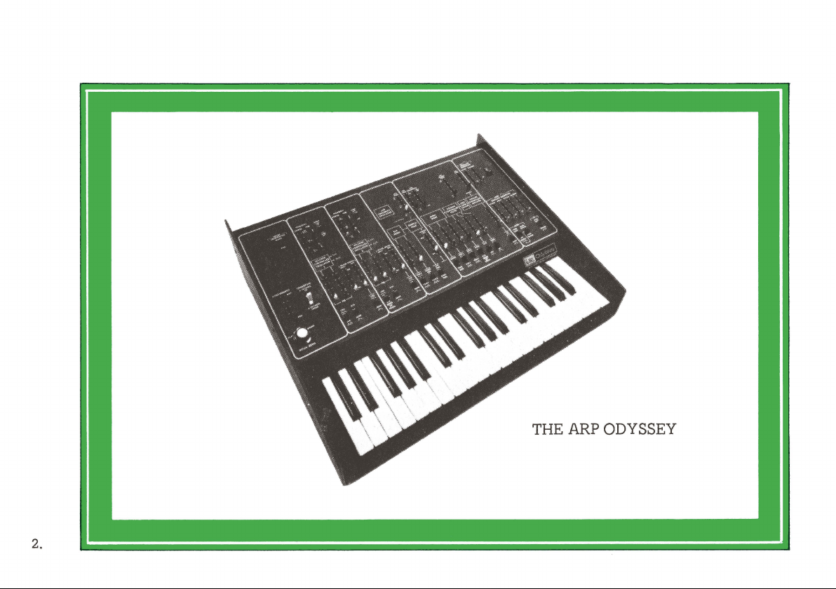
THE ARP ODYSSEY
Page 4
Contents
Getting Started . . . . . . . . . . . . . . . . . . . . . . . . . . . . 4
External Amplifier and Speaker . . . . . . . . . . . . 5
What Kind
Let's Begin
Sound Sources . . . . . . . . . . . . . . . . . . . . . . . . . . .
Modifiers . . . . . . . . . . . . . . . . . . . . . . . . . . . . . . . 1 9
...............................
How
Experiment
Experiment
Experiment 3. Phase Synchronization
Experiment 4. Noise
Experiment 5. Frequency Modulation
Experiment
Experiment 2. The
Experiment 3. The High-Pass Filter
of
your
Odyssey Works
1.
2.
1.
Amp Works Best
Listening to Waveforms
Pulse Width Modulation
...................
Ring Modulation
VCA
.............
................
...........
................
.........
......
......
.......
........
10
11
14
15
20
21
22
Experiment 4. The VCF . . . . . . . . . . . . . .
Controllers
5
6
7
7
7
Hints
Instant Odyssey . . . . . . . . . . . . . . . . .
Patches . . . . . . . . . . . . . . . . . . . . . . . .
Specifications
·
Give
Copyright 1976 by ARP Instruments, Inc.
..............................
Keyboard and Pedals . . . . . . . . . . . . . .
ADSR and AR Envelope Generator
Sample and Hold
Low Frequency Oscillators
Pitch Bend Control . . . . . . . . . . . . .
External Audio Input . . . . . . . . . . . . . . . . . . 37
Interface Jacks . . . . . . . . . . . . . . .
Panel Control Description Chart.
on
Using Your Odyssey
.........................
Your Odyssey a Little Brother . . . .
.....................
320 Needham Street
Newton, Massachusetts 02164
Second Edition
First Printing
..............
.......
.................
...
March, 1976
.........
......
.......
.........
......
...
Back Cover
....
39,
55,
..
22
28
29
30
33
36
36
37
40
41
42
43-54
56
3.
Page 5
The Odyssey belongs
A variable synthesizer,
allows
you
to shape every aspect
attack
and decay
Odyssey
is
equipped with controls
precisely shape each and every parameter
to
the class
as
opposed
to
the harmonic structure. Your
of
Variable synthesizers.
to
a Preset synthesizer,
of
a sound, from the
that
will let
of
you
the sound
you are creating.
Synthesizers create sounds electronically in much the
same fashion
acoustically. There are definite elements
when
put
precisely reproduce anything from a clarinet
that
any natural sound is created
of
sound which,
together in different combinations, will
to
a
jackhammer. The Odyssey is a musical instrument
comprised
each one
of
a number
is
designed
of
different electronic circuits;
to
control an element
of
sound.
This manual is an operational guide for the Odyssey,
but
it
should also give
you
a working knowledge
of
electronic music functions.
Checklist:
• Fill
out
your warranty card and send it in.
• Save the carton (It can be used
to
protect your Odyssey
until you get a carrying case).
• Place the Odyssey on a suitable playing surface (Don•~
worry about ventilation; it
won't
get hot).
Page 6
EXTERNAL AMPLIFIER AND SPEAKER
WHAT KIND
OF
AMP WORKS BEST?
The Odyssey, like all electronic musical instruments,
is designed
loudspeaker system. This external equipment (amplifier
and loudspeaker) may be a guitar amplifier, P.A. system,
an electronic organ, recording console,
fidelity
rear panel
and a smaller
in the following manner:
to
be connected
or
stereo system. Two
of
the
synthesizer-a
phone
jack labeled "High."
• If
you
are planning
into a guitar amplifier, use the synthesizer's
"Low"
used for this connection.
•
If
a hi-fi amplifier, use the
An
models. In the event
input,
moments
jacks so
controlled
output.
you're
using the synthesizer with an organ
input
jack
it
will
to
install one. Ask
the
volume
by
to
an amplifier and
or
even a high
outputs
to
A standard guitar cord can be
is
already available
only
take a serviceman a few
of
the
expression pedal
are provided
phone
jai:::k
labeled
Use
the
plug
your
synthesizer
output
your
the synthesizer can be
organ
him
marked
on
most organ
is
lacking this
to
of
on
"Low"
outputs
"High."
wire
the
the organ.
the
or
The whole idea
capability
sound using
amplification system for synthesizers should introduce as
little distortion
P.A. systems usually produce
synthesizers. Likewise a bass guitar amplifier is probably
the
worst kind
bass guitar amps usually have poor high frequency
response. Some lead guitar amps also have a lot
distortion and coloration.
through such an amp,
characteristic
Sometimes, however,
and an amplifier with a great deal
will produce just
Also,
don't
phasers, fuzz-wow pedals, equalizers and
your
Odyssey . You can get interesting results. The
Odyssey can also be used as an accessory device for
electronic musical instruments through use
audio
input
of
a synthesizer is
to
shape and
the
or
of
of
be afraid
jack.
control
synthesizer's controls. Therefore
coloration as possible.
amplification for synthesizers because
your
the amplifier rather
the
the
sound
to
every aspect
the
cleanest sound with
If
you
play
sounds will
combination
of
you
might be looking for.
use accessory devices, such as
to
give
you
the
of
a musical
the
ideal
For
this reason,
of
your
synthesizer
tend
to
be
than
the
synthesizer.
of
the synthesizer
its own coloration
so
forth
with
other
of
the
external
5.
Page 7
6.
By
now your curiosity is probably beginning
itself, and
In
this case, simply
tion
patches starting
some basic ideas
you
may wish
of
the control functions, and
on
of
to
turn
to
page 43. While these patches provide
the vast potential
start playing immediately.
page 39, read the brief descrip-
then
set
that
to
exert
up
any
of
lies within
the
the
Odyssey, you'll ultimately discover an ever greater
number
of
new and exciting sounds and effects
on
your
own.
If
you
prefer
to
systematically examine each control
your Odyssey before playing, continue
information which follows.
on
to
the
of
Page 8
HOW YOUR ODYSSEY WORKS
Generally speaking, all
Odyssey perform one
1.
Signal sources:
ultimately be shaped into musical sounds.
2. Signal Modifiers: the
signal modifiers where the timbre (or tone quality)
changed
3. Controllers: devices which determine
characteristics
modifiers. For instance,
which produces a voltage
pitch
generator creates an attack and decay signal
controls the Voltage Controlled Filter (VCF)
the
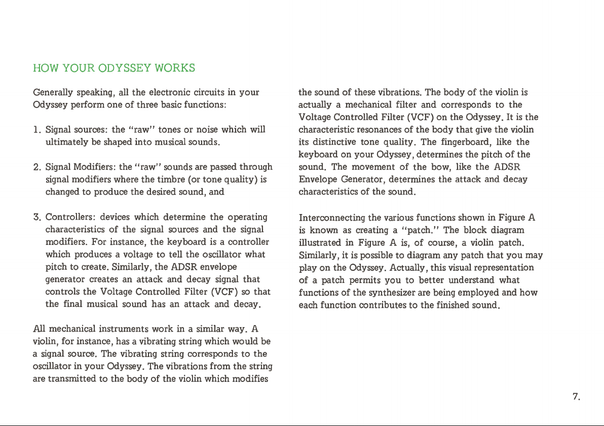
All
mechanical instruments work in a similar way. A
violin, for instance, has a vibrating string which would be
a signal source. The vibrating string corresponds
oscillator in your Odyssey. The vibrations from the string
are transmitted to the body
to
produce the desired sound, and
to
create. Similarly, the ADSR envelope
final musical sound has an attack and decay.
the
electronic circuits in
of
three basic functions:
the
"raw"
tones or noise which will
"raw"
sounds are passed through
of
the signal sources and
the
keyboard
to
tell the oscillator what
of
the violin which modifies
your
the
operating
the
signal
is
a controller
so
to
is
that
that
the
the sound
actually a mechanical filter and corresponds
Voltage Controlled Filter (VCF)
characteristic resonances
its distinctive tone quality. The fingerboard, like the
keyboard on your Odyssey, determines the pitch
sound. The movement
Envelope Generator, determines the attack and decay
characteristics
Interconnecting the various functions shown in Figure A
is
known as creating a
illustrated in Figure A
Similarly, it
play
of
functions
each function contributes
of
these vibrations. The body
of
the
body
of
the
bow, like
of
the sound.
"patch."
is,
of
course, a violin patch.
is
possible
on
the Odyssey. Actually, this visual representation
a patch permits you
of
the synthesizer are being employed and how
to
diagram any patch
to
better
to
the finished sound.
of
the violin
on
the Odyssey. It
that
give
the
The block diagram
that
understand what
to
the
the
violin
of
ADSR
you may
is
is
the
the
7.
Page 9
FIGURE
A.
VIOLIN
BOW
DRAWN
ACROSS
STRING
CAUSING
VIBRATIONS
(Signal
Source)
BODY
OF
VIOLIN
AS A
RESONATOR
THE
ACTS
FILTER/
(Modifier)
I--+-
OUTPUT
VIOLIN
SOUND
8.
I
FINGERS
CONTROL
BY
THE
AGAINST
FINGERBOARD
PITCH
PRESSING
STRING
THE
AXXE
I
KEYBOARD
CONTROLS
PITCH
+
OSCILLATOR
WAVEFORMS
AND
NOISE
(Signal
Source)
t
I
MOVING
FINGERS
AND
FORTH
PRODUCES
VIBRATO
(Controller)
I
LFO
PRODUCES
VIBRATO
(Controller)
BACK
CONTROLLED
VOLTAGE
FILTER
(Modifier)
t
I
DRAWING
ACROSS
STRINGS
ATTACK
DECAY
(Controller)
i----.
I
ADSR
ENVELOPE
GENERATOR
(Controller)
BOW
THE
SHAPES
AND
OUTPUT
VIOLIN
SOUND
Page 10
NOISE
GENERATOR
..
i--.,
.____
AND
I
[ I
I
-1
SAMPLE
HOLD
MIXER
CONTROLLED
~
OSCILLATORS
- - - -
11-
VOLTAGE
j'
'
--
- - - - -
-
'
,_
RING
MOD
SAMPLE
AND
HOLD
' .
u
-
FREQUENCY
OSCILLATOR
TRIGGER
AUDIO
MIXER
~
T
LOW
VOLTAGE
..
CONTROLLED
FILTER
'
VOLTAGE
CONTROLLED
-
AMPLIFIER
..
HIGH
PASS
FILTER
'
ADSR
AND
AR
PEDAL
ENVELOPE
GENERATORS
•
t
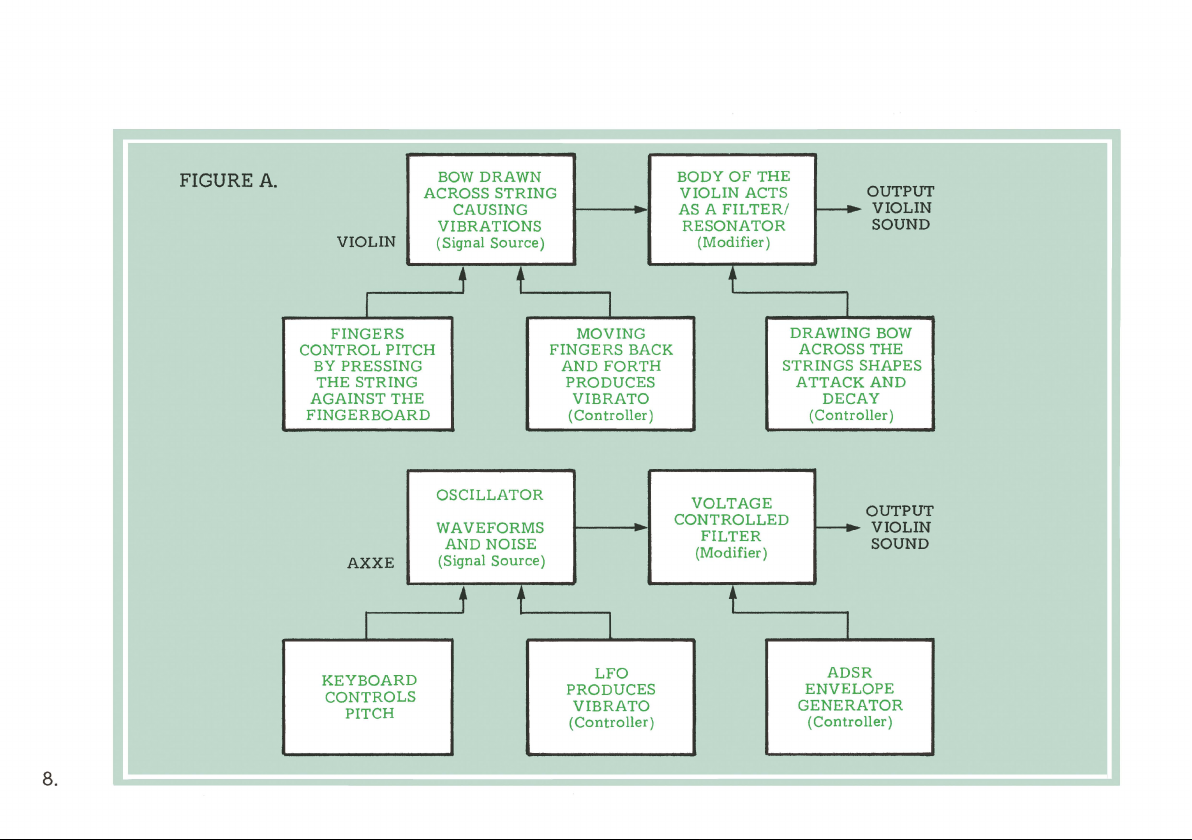
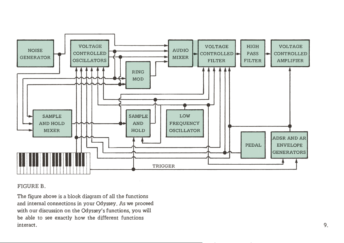
FIGURE
The figure above
and internal connections in
with our discussion
be able to see exactly how the different functions
interact.
B..
is
a block diagram
your
on
the
Odyssey's functions,
of
all the functions
Odyssey.
As
we
you
proceed
will
9.
Page 11
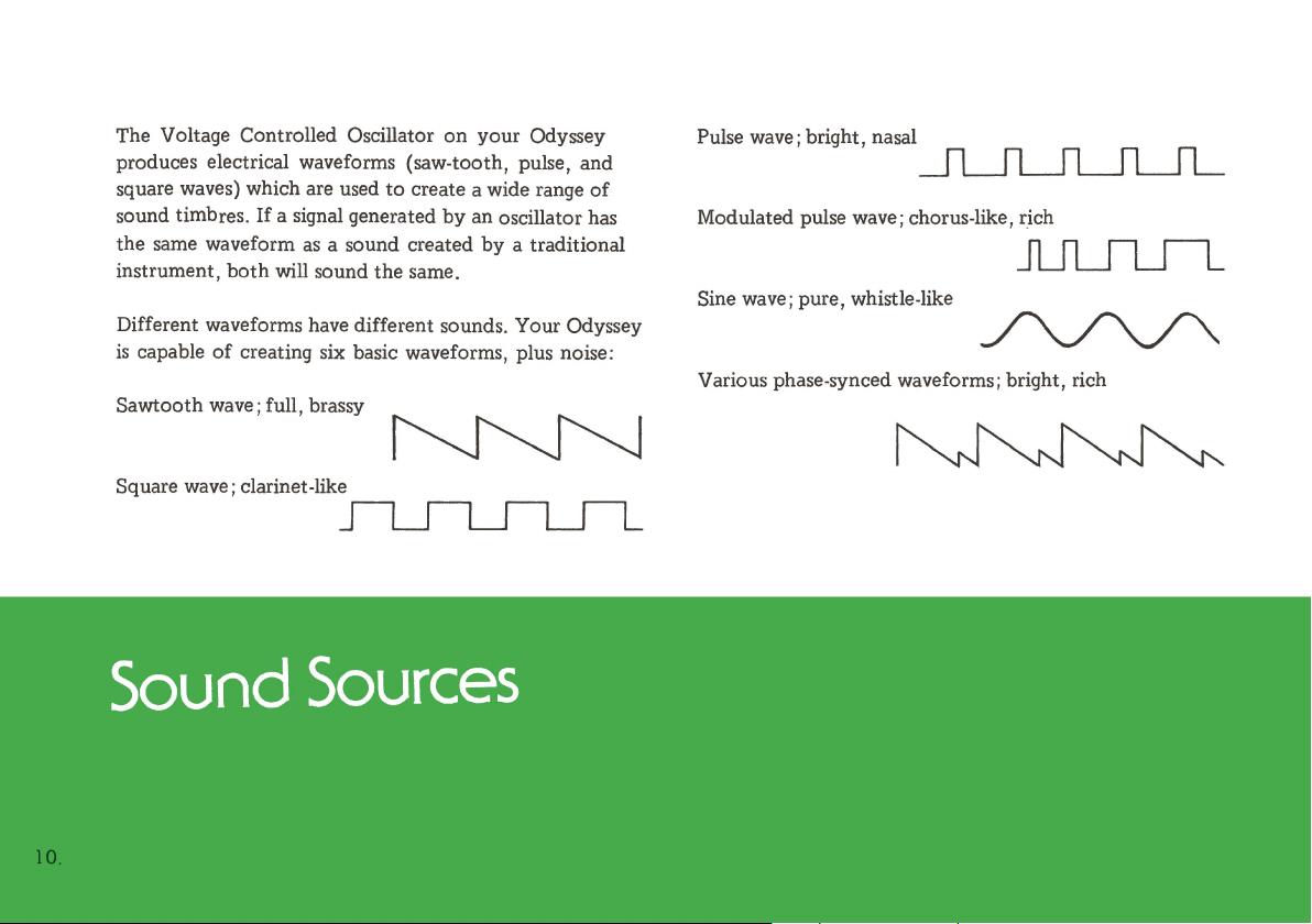
The Voltage Controlled Oscillator
produces electrical waveforms (saw-tooth, pulse, and
square waves) which are used
sound timbres. If a signal generated
the same waveform
instrument,
Different waveforms have different sounds. Your Odyssey
is
capable
Sawtooth wave; full, brassy
Square wave; clarinet-like
both
of
as
a sound created
will sound the same.
creating six basic waveforms, plus noise:
on
your Odyssey
to
create a wide range
by
an oscillator has
by
a traditional
of
Pulse wave; bright, nasal
Modulated pulse wave; chorus-like, rich
Sine wave; pure, whistle-like
Various phase-synced waveforms; bright, rich
Page 12
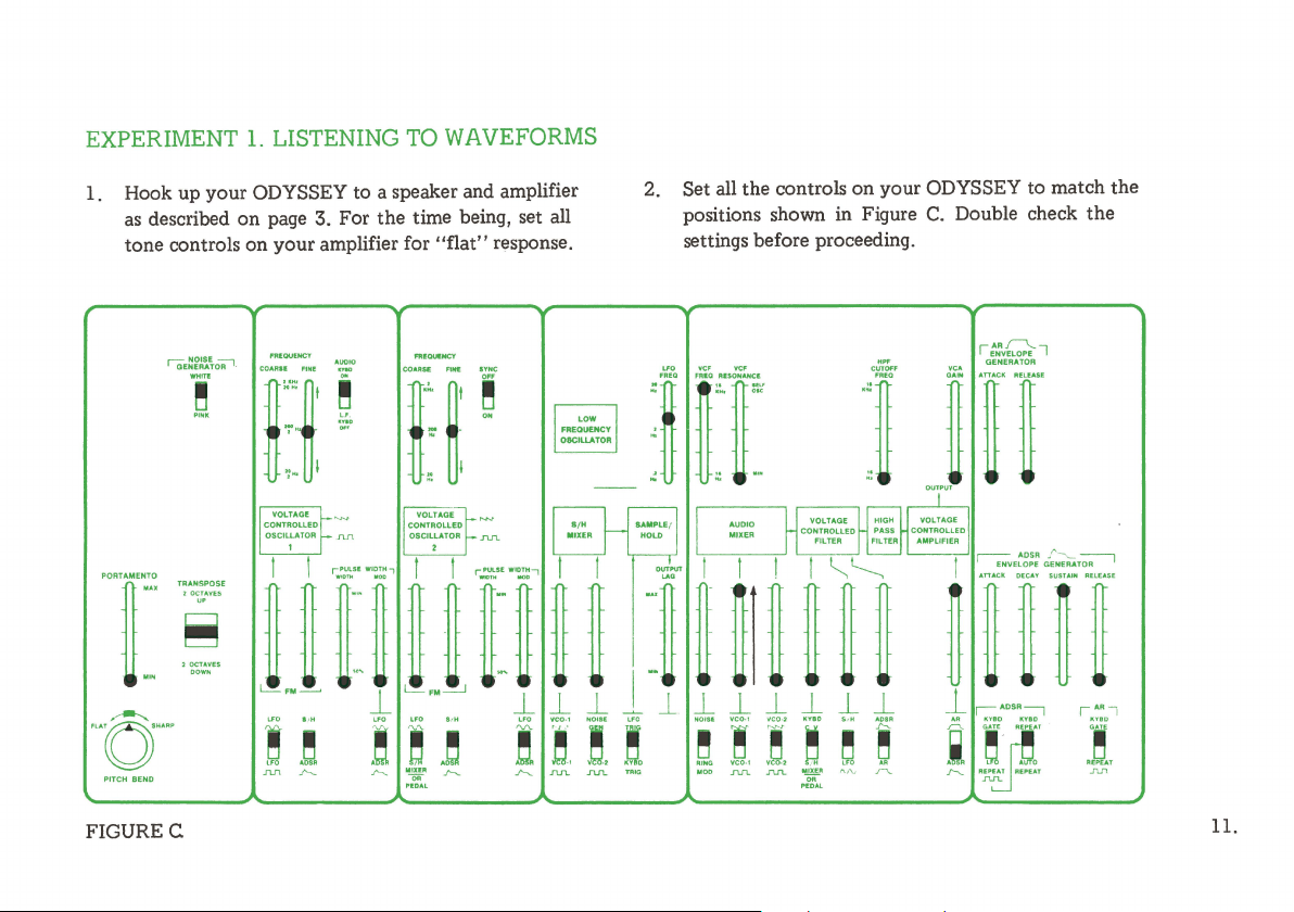
EXPERIMENT 1. LISTENING TO WAVEFORMS
1. Hook up your ODYSSEY to a speaker and amplifier
as
described
tone controls
PORTAMENTO
[
PITCH BENO
on
!.
page 3. For the time being, set all
on
your
amplifier for
"flat"
response.
2. Set all the controls
positions shown in Figure
settings before proceeding.
LFO
VCF
VCF
'.
i
[I
on
your ODYSSEY to match the
C.
Double check the
c:Ji~
VCA
r::vGe7
GENERATOR
] J Ii
FIGURE C
11.
Page 13
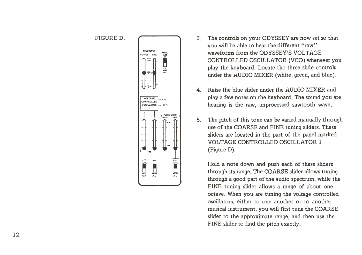
FIGURED.
CC:il.flSE FINE
,:::~I e
i~o Hz
~
~"'
I
VOLTAGE
CONTROLLED
OSCILLATOR
1
3. The controls on your ODYSSEY are now set
you
will be able to hear
the
different
"raw"
so
that
waveforms from the ODYSSEY'S VOLTAGE
CONTROLLED OSCILLATOR (VCO) whenever
play the keyboard. Locate
the
three slide controls
under the AUDIO MIXER (white, green, and blue)
you
..
4. Raise the blue slider under the AUDIO MIXER and
play a few notes
JU1
hearing
is
on
the keyboard. The sound
the
raw, unprocessed sawtooth wave.
you
are
12.
!
LFO
.fUl
~
AOS.i
~
5. The pitch
use
sliders are located in
of
this
tone
can be varied manually through
of
the COARSE and FINE tuning sliders. These
the
part
of
the panel marked
VOLTAGE CONTROLLED OSCILLATOR 1
(Figure
Hold a note down and push each
D~
of
these sliders
through its range. The COARSE slider allows tuning
through a good part
FINE tuning slider allows a range
octave. When
oscillators, either to one another
musical instrument, you will first
slider
to
the approximate range, and then use
FINE slider
to
of
the audio spectrum, while the
of
about one
you
are tuning the voltage controlled
or
to
tune
the COARSE
find the pitch exactly.
another
the
Page 14
6. The slide switch next
frequency
hundred when this switch
position. This
hearing; consequently
continuous
of
clicks. The rate
controlled
adjusting
of
VCO 1
is
far below
tone
but
by
the keyboard,
the
tuning sliders.
of
to
the
tuning sliders lowers the
by
a factor
you
only a more
this low frequency signal
of
about one
is
placed in its L.F.
the
range
of
will
not
hear any
or
less rapid series
but
can be varied
human
is
not
by
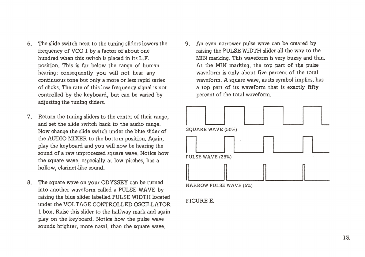
9. An even narrower pulse wave can be created
raising the PULSE WIDTH slider all
MIN marking. This waveform
At
the MIN marking,
waveform
waveform. A square wave, as its symbol implies, has
a
top
percent
is
only about five percent
part
of
its waveform
of
the
total waveform.
the
top
the
way
is
very buzzy and thin.
part
of
the pulse
of
the
that
is
exactly fifty
by
to
the
total
7. Return
and set
Now change
the AUDIO MIXER
play the keyboard and
sound
the
hollow, clarinet-like sound.
8. The square wave on your ODYSSEY can be turned
into
raising
under
1 box. Raise this slider
play
sounds brighter, more nasal,
the
tuning sliders to
the
slide switch back
the
slide switch under the blue slider
to
of
a raw unprocessed square wave. Notice how
square wave, especially
another
on
waveform called a PULSE
the
blue slider labelled PULSE WIDTH located
the
VOLTAGE CONTROLLED OSCILLATOR
the
keyboard. Notice how the pulse wave
the
center
of
to
the
audio range.
the
bottom
you
will now be hearing
to
the halfway mark and again
position. Again,
at
low pitches, has a
WAVE
than
the square wave.
their range,
the
by
of
SQUARE
PULSE
WAVE (25%)
NARROW
FIGURE
WAVE (50%)
PULSE
WAVE
E.
L
(5%)
13.
Page 15
14.
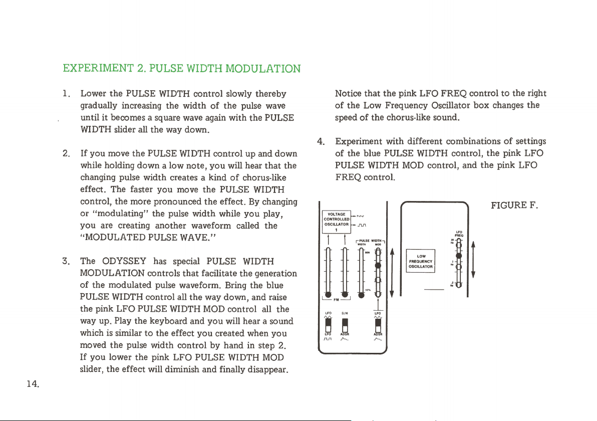
EXPERIMENT 2. PULSE WIDTH MODULATION
1. Lower
2.
3. The ODYSSEY has special PULSE WIDTH
the
PULSE WIDTH control slowly thereby
gradually increasing the width
until it becomes a square wave again with
WIDTH slider all the way down.
If you move the PULSE WIDTH control up and down
while holding down a low note,
changing pulse width creates a kind
effect. The faster
control, the more pronounced the effect.
or
"modulating" the pulse width while
you
are creating another waveform called the
"MODULATED PULSE WAVE."
MODULATION controls
of
the modulated pulse waveform. Bring the blue
PULSE WIDTH control all
the pink LFO PULSE WIDTH MOD control all the
way up. Play the keyboard and
which
is
similar
moved
If
slider,
the
you
lower the pink LFO PULSE WIDTH
the
effect will diminish and finally disappear.
you
move
to
the effect
pulse width control
of
the
pulse wave
the
you
will hear
of
chorus-like
the
PULSE WIDTH
By
you
that
facilitate the generation
the
way down, and raise
you
will hear a sound
you
created when
by
hand in step 2.
PULSE
that
the
changing
play,
you
MOD
Notice
that
the pink LFO FREQ control
of
the
Low Frequency Oscillator
speed
of
the chorus-like sound.
4. Experiment with different combinations
of
the blue PULSE WIDTH control,
PULSE WIDTH
FREQ control.
MOD
control, and
U'O
....
box
changes the
the
the
FIGURE F.
:It
to
the right
of
settings
pink LFO
pink LFO
Page 16
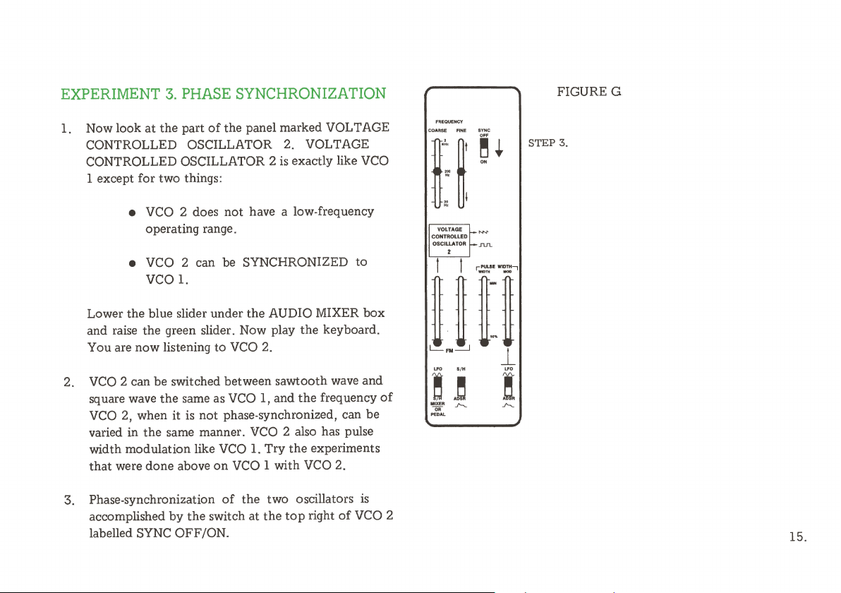
EXPERIMENT 3. PHASE SYNCHRONIZATION
FIGURE G
Now look
1.
CONTROLLED OSCILLATOR 2. VOLTAGE
CONTROLLED OSCILLATOR 2
1 except for two things:
at
the
part
of
the panel marked VOLT AGE
is
exactly like
• VCO 2 does
operating range.
• VCO 2 can be SYNCHRONIZED to
not
have a low-frequency
vco 1.
Lower the blue slider under
and raise the green slider. Now play the keyboard.
You are now listening to VCO 2.
2.
VCO
2 can be switched between sawtooth wave and
square wave
VCO
varied in the same manner. VCO 2 also has pulse
width modulation like
that
were done above
3. Phase-synchronization
accomplished
labelled SYNC OFF/ON.
the
2, when it
by
same as VCO 1, and
is
not phase-synchronized, can be
the
the
VCO
L Try
on
VCO
of
the
switch at
AUDIO MIXER box
the
the
experiments
1 with
VCO
two oscillators
the
top
right
VCO
frequency
2.
is
of
VCO
of
SYNC
STEP
3.
VOLTAGE
CONTROLLED
OSCILLATOR
~.
.n.n.
'
2
15.
Page 17
16.
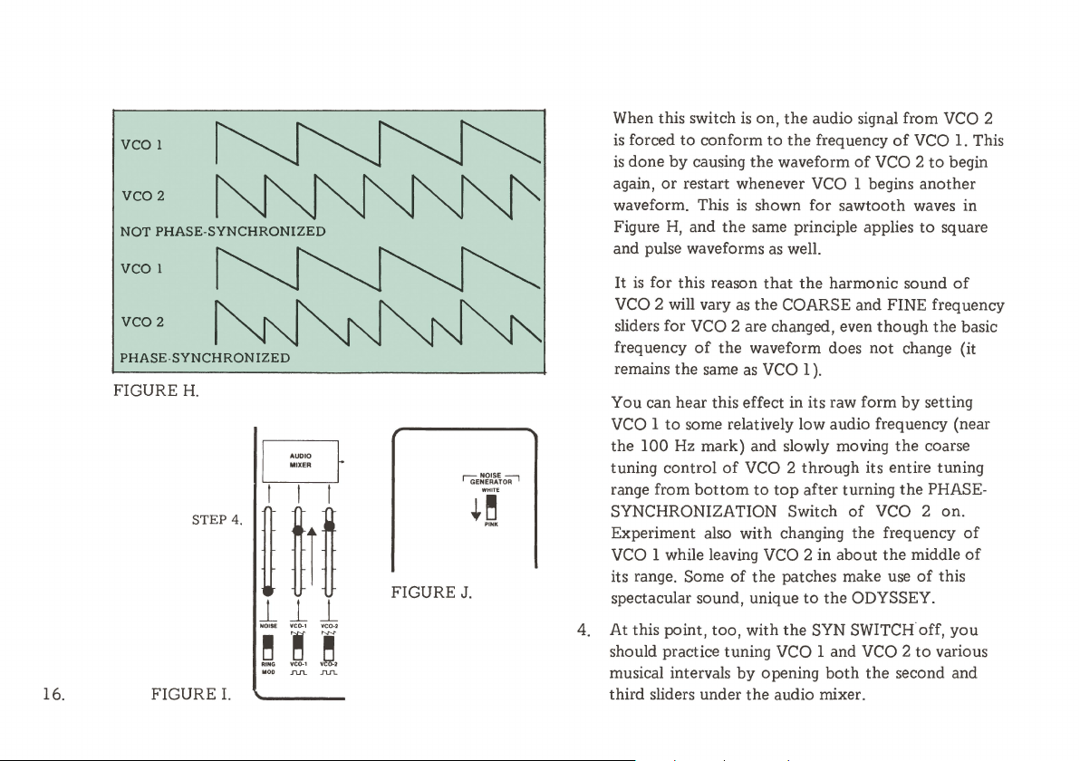
PHASE-SYNCHRONIZED
FIGURE
H.
STEP
4.
J_ J_ J_
FIGURE
I.
AUDIO
MIXER
'GE~fk~~o-;-,
I
+O
~I~
~
NOISE VC0-1 VC0•2
~
! =
""'
,,.._,
MOO
.~,
.f"l.IL .n.n..
FIGURE J.
When this switch
is forced
is
again,
waveform. This
Figure
and pulse waveforms
It
VCO 2 will vary
sliders for VCO 2 are changed, even though the basic
frequency
remains the same
You can hear this effect in its raw form
VCO 1
the 100 Hz mark) and slowly moving
tuning control
range from
SYNCHRONIZATION Switch
Experiment also with changing the frequency
VCO 1 while leaving VCO 2 in about
its range. Some
spectacular sound, unique
4. At this point,
should practice tuning VCO 1 and VCO 2
musical intervals
third sliders under the audio mixer.
to
done
by
or
restart whenever VCO 1 begins another
H,
is
for this reason
to
some relatively low audio frequency (near
is
on,
the
audio signal from
conform
causing the waveform
and
of
bottom
to
the
frequency
is
shown for sawtooth waves in
the
same principle applies
as
well.
that
the
harmonic sound
as
the COARSE and FINE frequency
the waveform does
as
VCO 1
).
of
VCO 2 through its entire tuning
to
top
after turning
of
the patches make use
to
the ODYSSEY.
too
, with
the
SYN SWITCH off,
by
opening
both
of
of
VCO 2
not
change (it
by
the
the
of
VCO 2 on.
the
the
second and
VCO
middle
VCO
to
to
square
setting
coarse
PHASE-
of
this
to
various
1.
This
begin
of
of
of
you
2
Page 18
EXPERIMENT 4. NOISE
EXPERIMENT
5.
FREQUENCY MODULATION
1. Lower the blue and green sliders under the AUDIO
MIXER box and raise
notes on the keyboard and listen
are hearing what
is
known
the
white slider. Play a few
to
the
sound. You
as
WHITE NOISE. This
noise contains all frequencies in the audio spectrum
in equal amounts, and
noise you hear between stations on the
is
harmonically identical
FM
to
radio
band.
2. There
is
a noise generator switch located in the upper
left hand corner
position
of
of
this switch
the ODYSSEY. Change the
to
PINK and again play a few
notes on the keyboard. Whereas
contains equal amplitudes
NOISE contains equal energy
of
each frequency, PINK
of
WHITE
NOISE
each frequency.
Physically, this means that the higher frequencies are
present
PINK NOISE
noise because it sounds balanced
at
lower volumes than the lower frequencies.
is
the most musically useful kind
to
the ear, neither
of
too high and hissy, nor too low and rumbling. You
will see later how
ODYSSEY
to
use the
to
turn noise into a wide range
other
functions
on
of
exciting
the
sounds.
the
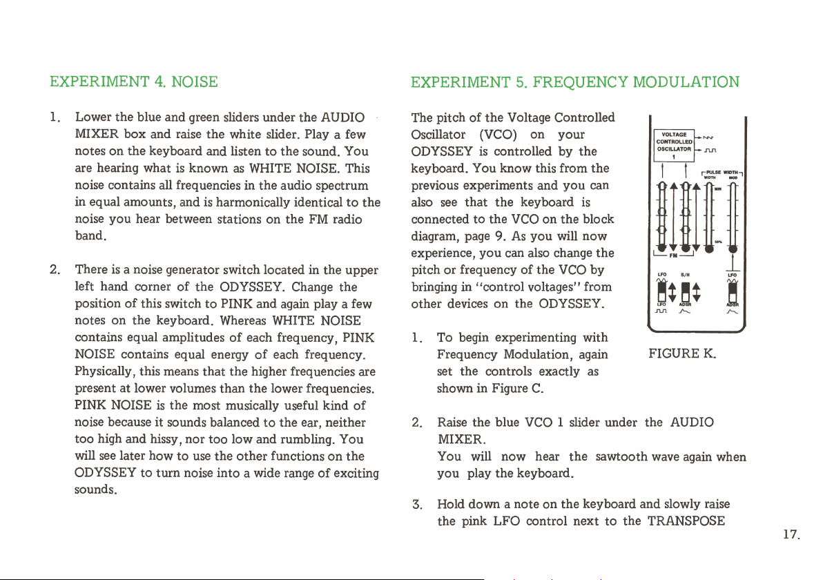
The pitch
Oscillator (VCO) on your
ODYSSEY
of
the
Voltage Controlled
is
controlled by the
VOLTAGE
CONTROLLED
I
OSCIU.ATOA
1
,..,,._,,.
.nn
keyboard. You know this from the
previous experiments and
also see
connected
diagram, page 9.
that
to
the
the
keyboard
VCO
As
experience, you can also change
pitch
or
frequency
of
you
can
is
on
the
block
you will now
the
the
VCO
by
bringing in ''control voltages'' from
other devices on the ODYSSEY.
1. To begin experimenting with
Frequency Modulation, again
set the controls exactly
shown in Figure
2. Raise the blue
C.
VCO
FIGURE
as
1 slider under the AUDIO
K.
MIXER.
You will now hear
the
sawtooth wave again when
you play the keyboard.
3. Hold down a note on the keyboard and slowly raise
the pink LFO control next
to
the TRANSPOSE
17.
Page 19

SWITCH. Notice
that
becomes deeper as
that
a slow vibrato
you
is
introduced
raise this control.
4. With this LFO control up about 1/4, adjust the LFO
FREQ control and observe how the vibrato rate can
be changed from very slow
to
very fast. About
3/4
should provide a pleasing vibrato rate.
you
raise the yellow S/H slider,
the
wider the pitch
variations. At least one S/H Mixer slider must be
raised in order for the yellow S/H control
activated.
8.
Bring the yellow S/H slider back down, and lower the
white S/H Mixer slider.
to
be
18.
5. Change the first slide switch from LFO
LFO
nn
LFO
nn
this slider,
and the
. Instead
of
produces a trill. Notice
the
bottom
top
note moves depending
note
a smooth vibrato, the
of
the trill stays
J"'v"
that
on
the setting
as
you
the
to
raise
same
of
the slider. Try tuning the trill for different intervals,
like a fifth, octaves, etc. If
SPEED control,
the
trill can become a useful musical
timbre, especially when
the
you
increase the LFO
trill
is
tuned
to
simple
intervals, like octaves.
6. When
you
have finished experimenting with trills,
bring the LFO
FM
slider back down.
7. Now raise the white slider under the S/H Mixer box.
While holding down a note
on
the
keyboard, slowly
raise the yellow S/H control under the VCO. Notice
that this control causes pitch
of
the
VCO
to jump
around in a completely random manner. The higher
9. Now set the slide switch under the yellow knob
the ADSR position, and then raise the yellow slider.
Notice how the pitch rises. Leave this control set
that
you have raised the pitch about an octave.
10. Now bring up all the way the four red ADSR
ENVELOPE GENERATOR CONTROLS (located in
the lower right hand corner
11. Again play
of
the
The settings
speed
on
the keyboard. You will hear the pitch
sound rise and fall each time
of
the ADSR controls will determine
of
the
pitch change. You will learn more about
these controls when
11
Controllers.''
you
of
the panel).
get
to
you
hit a key.
the section on
to
so
the
Page 20

Modifiers are electronic devices
and change its sound. Consequently a modifier must have
an input and an
simple modifier since it changes the nature
signal
that
output.
passes through its circuitry.
A tone control
that
can process a signal
on
a hi-fi set is a
of
the
sound
The ARP ODYSSEY contains four modifiers, the Voltage
Controlled Filter (VCF), the Voltage Controlled
Amplifier (VCA), the High Pass Filter (HPF), and the
Ring Modulator. Any signal
AUDIO MIXER, i.e., Noise,
through the VCF, HPF and the
output
of
the ODYSSEY.
that
is
introduced into the
VCO
or
VCO
VCA
before reaching the
must pass
19.
Page 21

EXPERIMENT
1.
RING
MODULATION
20.
Lower
MIXER BOX, and raise
position
Noise
switch for VCO 2
and listen
listening
shown in Figure
controls
VCO 1 and VCO 2, a single complex
contains all
frequencies. This means
the
blue and green sliders
the
white slider again. Change
of
the slide switch
to
RING MOD. Make sure
is
to
the
RING MODULATOR. While
to
it
you
should
L.
of
its own. It produces, from
the
sums and differences
• The raw sound produced from
modulator
VCO 1 and VCO 2; and
under
the
that
off. Play a few notes
think
of
The RING MODULATOR has
that:
depends entirely
to
nn
VCO2
I
MODULATOR
-
vco
1
I
nn
under
the
white slider
the
PHASE SYNC
on
the
block diagram
the
pulse
output
of
the
two oscillator
the
on
the
a lesser
RING
AUDIO
the
from
the
keyboard
you
are
no
outputs
signal which
ring
tuning
of
extent
on
of
VOLTAGE
CONTROLLED
FILTER
FIGURE
the
pulse
width
settings for each one.
Experiment with these. Note in particular
sounds from
necessarily have any standard musical pitch in
relation
they
are synchronized
VCO 2;
• The overtones
signal will
standard harmonic series.
extremely complex, like those
gongs, and
All
of
further
lator
signal. Some
L.
the
RING MODULATOR
to
the
pitch
of
either oscillator. (Unless
by
try
that).
of
the RING MODULATOR
not
necessarily conform
other
metallic
these, in fact, can
modifications
HIGH
PASS
FILTER
of
of
the
the
SYNC switch
They
of
a bell, chimes,
or
percussive sounds.
be
simulated
a suitable ring
patches illustrate this.
-
that
do
not
on
to
the
may be
by
modu-
OUTPUT
t
VOLTAGE
CONTROLLED
AMPLIFIER
Page 22

EXPERIMENT 2. THE VCA
Set the controls
1.
ODYSSEY to match the
settings in Figure
time, raise the white NOISE
slider under the AUDIO
MIXER.
you
keyboard, you will hear
noise sound.
While
2.
on the keyboard, gradually
lower the red ADSR slider
under the
this slider acts like a volume
control. Bring this control
all the way down and the
sound will
disappear.
With this ADSR control all
3.
the way down, slowly raise
As
hit a note
holding down a note
on
before, when
on
VCA.
Notice
completely
C.
your
This
the
the
that
FIGUREM.
fCA.
.,.,.
l
STIP3
J
t
l
STIP2.
~
J_
l
..
,,_
~
....
.I'--..
the black
control also acts like a volume control. The difference
between
GAIN control is obvious. The ADSR control depends
playing the keyboard. The
nothing
allows a certain amount
at
all times. Bringing up
signal pass through only when
Actually,
voltage produced by
GENERATOR to
through. The settings
GENERATOR controls will determine the speed with
which the
four ADSR ENVELOPE GENERATOR controls
observe this effect.
VCA
GAIN control. Notice how this
the
operation
to
do with
to
VCA
the
be more specific,
"open"
opens and closes. Experiment with the
of
the
ADSR slider and
VCA
GAIN control has
keyboard. The
of
signal
the
red ADSR control will let the
the
the
ADSR ENVELOPE
the VCA and let signal pass
of
the ADSR ENVELOPE
VCA
GAIN control
to
pass through
the
keyboard is used.
ADSR slider lets the
the
VCA
the
to
on
VCA
21.
Page 23

EXPERIMENT
3.
THE HIGH PASS FILTER
EXPERIMENT 4. THE VCF
22.
The HIGH PASS FILTER (HPF}
modifier.
HPF
"Boominess" from low bass notes, and in simulating
certain instrumental sounds. The HPF
controlled. Try moving
range while holding down a low
It
attenuates frequencies below
cutoff
frequency slider.
the
HPF control slowly over its
is
another signal
the
setting
It
is useful in eliminating
is
not
voltage
note
on
the
keyboard.
FIGUREN.
of
""
tl
its
The Voltage Controlled Filter (VCF)
important modifier
responsible for taking
Modulator, and the Noise Generator and shaping
into useful musical sounds.
The VCF in
pass filter." Low-pass means
audio frequencies below a certain point ( called the
off
point")
point.
1.
Set
Figure
VCO
MIXER. Also,
that any signal passing through
heard.
2. Play a
have
control and listen
gets brighter and louder as
does so because
of
frequencies pass through.
your
and will filter
the
controls
0.
is
entering the VCF through the AUDIO
note
to
hold it down. Slowly raise
the
filter,
on
any synthesizer. The VCF
the
raw signals from
ODYSSEY
out
on
your
In this setting,
the
VCA GAIN control
in
the
middle
to
the
you
are raising
thereby
letting more and more high
is
technically called a
that
all frequencies above this
ODYSSEY according
the
of
the
effect. Notice how
you
is
the
most
the
VCO, Ring
the filter will pass all
sawtooth wave from the
is
raised
the
VCF will be
keyboard. You
the
VCF FREQ
the
raise this control. It
the
cut-off frequency
is
them
"low
"cut-
to
so
don't
sound
Page 24

PORTA.MENTO
n ·
il
"'"
PITCH BENO
'GE=f~~\ofi7
TRANSPOSE
2 ocr,wEs
..
2 OCTAVES
i
"'
DOWN
COARSI!
FINE
~
L...-.
:i:-~.
r[
·:•
I
COARSE
"~
.
~
~
"'
VOLTAGE
CONTROLLED
OSCILLATOR
2
SVNC
~
o,
I
JVL
LOW
YCF YCF
'-'O
FREQ
FRl.0
]
l
RESONANCE
,.
AUDIO
MIXER
u•
,~
VOLTAGE
CONTROLLED
FILTER
FIGURE
3. Slowly lower the VCF FREQ control. The highs will
4. Lower the blue
0.
fade and finally the whole signal will be filtered
VCO
1 slider under the AUDIO
MIXER and raise
the
white NOISE slider. Again open
out.
and close
FREQ control.
5. Notice how the noise can be made
by opening and closing the filter slowly. Raise the
the
VCF
by
raising and lowering the VCF
to
sound like surf
23.
Page 25

FIGURE
STEP
P.
4.
STEP
VOLTAGE
CONTROLLED
FILTER
5.
RESONANCE slider about half way up and
same experiment. Notice how the noise now takes
a whistling quality. This pitch-like whistling
by
the
resonance
a narrow band
frequency. The more resonance
emphasis, and consequently
of
the filter. Resonance emphasizes
of
frequencies just
at
the filter
you
add, the more
the
more pitched the
sound becomes.
6. Lower the noise slider and listen again
to
sawtooth wave. Again move the VCF FREQ control
up and down slowly with different settings
RESONANCE control. Notice
resonance
actually hear
is
between
the
the
individual harmonics
1/2
and
that
when
3/4
marks you can
of
you slowly sweep the VCF FREQ up and down.
7. ff
you
leave the RESONANCE control about half
way up, and sweep the VCF FREQ up and down,
can create a
"wow"
type
of
sound. Leave
FREQ control all the way down and raise the red
ADSR slider under the VCF all
you
hit a key on the keyboard, the ADSR
the
way up. When
ENVELOPE GENERATOR produces a signal which
try
the
is
caused
cutoff
the VCO
of
the
the
the sound
the
VCF
on
as
you
24.
Page 26

will open
a
"wow"
the ADSR slider will show
the response
ADSR slider under the VCA.
8. Lower the RESONANCE slider and experiment with
the
VCF. Try changing the settings
ENVELOPE GENERATOR controls.
and
close the VCF automatically, producing
sound. Experimentation with
of
this control and the response
different settings
of
the
the
the
similiarities between
ADSR slider under
of
the
four ADSR
setting
of
the
the
of
.~~~
,:"~;::½:~
-
~,
~
1•
MIN
STEP
CONTROLLED
FIGUREQ.
9.
VOLTAGE
FILTER
9. Lower the ADSR control again, and set
FREQ control about half way up. Now, set
switch under the yellow slider
yellow LFO
tremolo effect
and increase the LFO SPEED until
good tremolo sound.
10. Lower
labeled
this slider will allow
keyboard.
.../'J"'
the
LFO slider, and raise the black slider
KYBD
slider under the VCF. Notice
that
is created. Lower
CV
S/H under the VCF. Normally
you
to
control
to
LFO and raise
the
you
the
the
VCF
the
the
the
LFO slider
achieve a
VCF from the
25.
Page 27

FIGURER.
~'i~
,:ESO~•:"':.
-
OK
~
1t
IIIIN
~
STEP 11.
VOLTAGE
CONTROLLED
FILTER
11. Let's
try
controlling the VCF with the keyboard.
Set
the
controls
you
play on the keyboard, the pitch
on
the panel as above. Now when
noise will follow the note played
If
you
lower the black KYBD slider under
the keyboard will have no effect
12. Raise the yellow slider all
the
the white slider under the S/H Mixer
keyboard. Notice
the
random changes in
frequency.
of
the
filtered
on
the
keyboard.
the
VCF,
on
the pitch.
way up again, and raise
box.
Play
the
the
filter
26.
13. Plug the pedal into
of
your ODYSSEY. When the pedal is plugged in,
the
appropriate jack
on
the S/H Mixer is disconnected from the VCF. Set the
switch under
The PEDAL can now be used
VCF. The range
the setting
the
black slider
of
the pedal will be determined
of
the
black slider under
to
the
Pedal position.
to
open and close
the
VCF.
the
back
the
by
Page 28

14. The VCF can also function as an oscillator. Raise the
yellow slider under the VCF all
15. All three sliders under the AUDIO MIXER should be
down. Turn the RESONANCE all
tune the resulting
Set the switch under the black slider back
position. You can now hear a pure sine wave
generated by the filter.
tone
with
the
way.
the
way up and
the
VCF FREQ control.
to
the
KBD
FIGURES.
AUDIO
MIXER
VOLTAGE
CONTROlLED
FILTER
!
~l_.._,
STEP
15.
[[[~[[
J_ J_
"°'"
i
a
VC0-1
MOD
.nn.
J_ J_ J_ J_
~
i
""
~
.a
P.
~
J1.fL
l!Jll.R
..
PEDAL
e
/Vv
r,_,.
27.
Page 29

Controllers are devices on
to
create electrical signals which in
and sources on
obvious controller
keyboard produces a voltage which controls
can control the VCF. Other controllers
are the sample and hold, ADSR ENVELOPE
GENERATOR, HPF, LFO, PITCH BEND CONTROL,
and FOOTPEDAL.
By
this time you have had an opportunity
with each
functions
the
on
of
these controllers,
of
each
of
the
synthesizer which are used
turn
control modifiers
synthesizer. For instance,
the ODYSSEY
the controllers.
is
the
on
the
to
so
let's just review
keyboard. The
the
most
the
VCO
ODYSSEY
experiment
the
and
Page 30

KEYBOARD AND PEDALS:
The KEYBOARD produces two CONTROL VOLTAGES.
These voltages are
depressed
the
key played.)
control voltage corresponds
and
depressed.
The first control voltage
unless VCO 1 is set
keyboard
control voltage is
VCO 2 has SYNC switched on,
connected
directly control its frequency,
content,
(Try it.)
The first keyboard control voltage can also be connected
to
the
VCF; This was investigated during
the VCF.
It is
memory, which holds the last
on
keyboard,
the
second control voltage corresponds
is
to
as
do
VCF
by
important
the
same
if
none
or
one
the
keyboard.
the
control voltages correspond
If
two
or
to
disconnected from VCO
always_
VCO 2, although in this case
the
tuning sliders for VCO 2 in this case.
raising
to
know
(If
no
keys are depressed
more notes are depressed,
to
the lowest
is
always connected
the
L.F..
mode, in which case
connected
the
but
the
appropriate slider under
the
that
the
ODYSSEY has a built-in
note
key
1.
The second
to
VCO 2. When
keyboard is still
rather its harmonic
experiments with
played
key
to
the
the
depressed,
to
the
highest
to
VCO
it
does
on
the
is
on
last
first
1;
the
not
the
keyboard. This keeps
the
RELEASE cycle
generators, as we shall see.
The keyboard
associated with it. These include
slider and PORTAMENTO SWITCH. The TRANSPOSE
SWITCH will shift
exactly two octaves. The PITCH BEND control will be
discussed in a separate section.
PORTAMENTO
ODYSSEY
under
the PORTAMENTO pedal, raise
slider and listen
supplied with
PORTAMENTO. Thus
slider for a certain glide speed and
with
When the foot pedal
ODYSSEY, VCO 2 and the VCF can be controlled
(The signal from
disconnected
earlier.) Several
for wah-wah and
as,
the
VCF.
the
foot switch.
shown in Figure
your
by
on
the
the
is
a "sliding
As
you
to
the
ODYSSEY
the
inserting
of
the
other
the
pitch information around during
of
the
AR and ADSR envelope
ODYSSEY has several controls
the
PORTAMENTO
pitch
of
the
keyboard
effect."
M.
Raise
play
on
the
keyboard, hold down
the
resulting effect. The foot switch
is
used
you
can set
is
plugged
S/H Mixer
the
patches make use
effects.
the
then
into
the
is
foot pedal jack as explained
up
or
down
Set
up
your
the
ADSR control
PORTAMENTO
to
turn
on
the
PORTAMENTO
turn
it
on
and
back
of
your
by
automatically
of
the
foot pedal
off
it.
29.
Page 31

ADSR AND AR ENVELOPE
GENERATOR:
Each time a note
keyboard generates a "trigger" signal
attack from the ADSR. A complete cycle
ENVELOPE GENERATOR looks like this:
J
When a key is depressed, the
a speed determined by the setting
control. This attack is represented above by
"A."
automatically turns around and begins heading down
again at a rate controlled
30. part
is
pressed
---
When
of
KEY
DEPRESSED
KEY
RELEASED----.
the
attack has reached its peak, it
by
the cycle is represented as
on
the
output
the
"DECAY"
keyboard,
that
initiates an
of
of
the
ADSR rises at
of
the ''ATTACK''
the
control:
the
letter
"D."
the
the
letter
The
This
Output
eventually reach the Sustain Level
until
the
rate determined
This release portion
letter
The AR envelope generator is just like
generator except
level
the ADSR generator with
minimum and
complete cycle looks like this:
of
the ADSR ENVELOPE GENERATOR will
the
keyboard
output
of
"R."
is
the maximum level. This gives
,..,.
__
is
released. Upon release
the ADSR will
by
the setting
of
the cycle is represented
that
there is no decay, so
the
the
"Sustain'' control at maximum. A
KEY
DEPRESSED
KEY
RELEASED---~
"S''
drop
back down
of
the Release Control.
the
"Decay"
and stay there
of
the
key,
to
zero
by
the
the
ADSR
that
the
sustain
same effect as
control at
at
a
Page 32

PORTAMENTO
n
...
il
""
PITCH BENO
FIGURE T.
TRANSPOSE
2
O~TPAVE.'!',
COARII!
FINI!
[!
COARSE
FINE
SYNC
~
OH
~
~J
LOW
~o
YCF VCF CUTOFF
FREQ
FREQ
AISONANCI!
K,.,
o•c
" l
i
1t
..
AUDIO
MIXER
""
MIN
]
VOLTAGE
CONTROLLED
FILTER
""
FRIO
K~
"l
It
..
r-::vQ7
GENERATOR
GAIN
ATTACK
A,
..
,
~
I
OUTPUT
With
your
ODYSSEY controls set as in Figure T, depress
any key
AR generator a little way and depress a key again.
Continue
a little more until
on
the keyboard. Raise
to
do
this, each time raising
it
is all
the
attack
slider
the
attack
the
way up. Then move it down
on
the
control
again and repeat
slider.
Now experiment with VCA control
generator; move
the
whole procedure using
the
selector switch under
by
the
the
the
release
ADSR
VCA
31.
Page 33

FIGURE
U.
VOLTAGE
CONTROLLED
FILTER
control attenuator down and
four ADSR controls.
try
various settings
of
the
32.
FIGURE
V.
By closing the VCF freq slider and opening
attenuator under the VCF all
you
can
give
yourself a similar introduction
AR control
combinations
of
the VCF. Experiment
of
the VCF freq and control attenuator
the
way as in Figure
too
with various
settings, and with various mixes (by means
attenuators
and
VCO
Up
to
generators only from
switches
trigger
three switches down and set the
ODYSSEY for AR
as in Figure
slider from low
the second switch up, a series
(triggered)
This
is
to
the audio mixer)
of
signals from VCO 1
2.
now
you
have been triggering the envelope
the
keyboard. By means
at
the
bottom
the
envelope generators with
V.
Now
to
by
the LFO,
right
of
or
ADSR control
try
different settings
Figure
other
V,
the
LFO. Move all
controls
of
the VCF
of
high. With the first switch down
of
events will
but
only when a key
useful in simulating banjo-picking and strumming.
the
to
ADSR and
of
the
of
you
can also
of
the
LFO freq
be
produced
is
depressed.
third
input
the
your
or
VCA
and
U,
three
Page 34

SAMPLE AND HOLD
The sample and hold mixer (S/H mixer) selects and
combines signals
These signals can also be routed
VCF. Under each
labeled
plugged into the Odyssey,
switches selects control
disconnected from
switch position selects control by the
mixer.
''S/H
to
mixer
be fed
to
the sample and hold circuit.
to
control
of
these two functions is a switch
or
pedal.'' When the foot pedal
the
lower position
by
the
pedal;
the
back
of
the
VCO
if
the
foot pedal
Odyssey,
output
of
of
the
the
2 and
these
same
S/H
is
the
is
FqfQUENCV
COARSE
FINE
.,..c
...
~
ON
[[
VOLTAGE
CONTROLLED
OSCILLATOR
,..,
.n.n_
2
LOW
I.FO
....
]
FIGURE
W.
The sample and hold circuit
to control VCO
hear what it does listen first
before and
Figure
W.
By "sampling"
the
S/H mixer, the sample and hold circuit produces a
series
of
voltage levels. If these in
a VCO,
the sample and hold circuit selects either
keyboard
(Figure
you
the
X},
press a key. Using this with
1,
VCO 2, and/or the VCF. In order
then
experiment with the controls indicated in
at
a given instant the signal voltage from
result
is
a series
as
a triggering source. If
then
a new sample will
is
a controller;
to
VCO 2 as
turn
of
pitches. The switch under
the
be
the
it
is used only
you
have done
are used
the
LFO
keyboard
taken every time
S/H going into the
to
control
or
is
selected
to
the
B
~e
~R
..t-,._
""'"
./'-,..._
J'\J'L
.nn.
TIIIG
33.
Page 35

SAWTOOTH
INPUT
RANDOM
NOISE
INPUT
I
l
~
~l
J_ J_
VC0-1
NOISE
,,,
I g
a
.Q.
.I\.I1..
I'\J'1.
FIGURE
VCF can
LFO
is
intervals corresponding
LFO.
When
voltage levels will be random and so
pitches produced from VCO 2;
sampled are regular and periodic (any combination
VCO 1 and VCO 2 signals),
J_
rn•
Tfl1G
X.
give
you
selected,
the
signal sampled
random timbres
then
I I I I
I I I I I I I I I I
COMMAND PULSE1 1 1 I I I
1111111
I I I I I I
1 I I I I
HJjd
Musical
effect.
l~J
new samples will be taken at regular
J f J J J J f J
on
each
note.
If
to
the
frequency setting
is
primarily noise,
of
but
if
then
the
the
output
course will be
the
signals being
output
from
of
the
the
of
the
the
the
1 I I I I I I I I I
COMMAND
11
Musical
JI
sample and hold circuit will
also.
extremely simple.
VCO 1 sawtooth into the S/H mixer.
hold
through
halfway up, and
should hear a descending "staircase"
scale passage
freq and hear
l~J
It
may be an extremely complex one,
output
to
the
audio mixer. Set
or
PULSE
1111111111
effect.
J J r J J J J J
tend
For
an example
control VCO 2 and listen
the
the
VCO
1 freq
an arpeggio (Figure Y). Speed
the
repeating patterns.
I I I I I I
to
be a repeating
or
of
a simple one, switch
Use
the
to
LFO freq
at
about 2 Hz.
of
pitches, like a
pattern
it may
be
sample and
VCO 2
to
about
You
up
VCO 1
I
r
FI
34.
Page 36

LOW
FIGURE
Z.
VOLTAGE
1
output
of
N-.t
EB]
.I'-....
lag slider (Figure
voltage from
"min"
CONTROLLED
O'lCILU.TOA .n.n
The
changes
the same patch
slowly from
:i
VOLTAGE
CONTROUED
OSCILLATOR .n.n..
-~E1l
'"""
you
~
2
..t-....
have been listening to, move the slider
to
"max"
./'-... ..n.n, .11.IL
Z)
"smoothes
the
sample and hold circuit. With
and back again.
TIIIG
out"
J
J_
"o
a
FIGURE Y.
sudden
35.
Page 37

LOW
FREQUENCY
OSCILLATOR
PITCH BEND
CONTROL
36.
The LFO on your ODYSSEY,
is
used
to
create voltages which produce vibrato, trill,
tremolo, and
to the
output
used
to
wave
is
the ADSR ENVELOPE GENERATOR, via the REPEAT
SWITCHES.
other
effects when these voltages are applied
VCO
or
VCF. The LFO produces
and a square wave
create vibrato and tremolo effects and the square
used
to
create trills. The LFO
as
output.
you
have already seen,
both
The sinewave
is
also hooked
a sinewave
output
up
is
to
The Pitch Bend knob is a live performance control for
bending notes. It also extends
extra octave beyond normal. This control permits
realistically
of
effects and create sounds
traditional instruments.
When recreating the effect
instruments, however, limit the pitch deviation
approximately one half-step. This
common effect employed
who work with rock groups. Notice
position for the pitch bend knob
"dead zone" where turning the knob slightly either way
results in little
"feel"
to
look at
By taking advantage
is exactly up
BEND CONTROL as an auxiliary TRANSPOSE switch,
you
can use it as a guitar "string pull" effect with a hard
stop when the instrument is exactly in tune
switch all the way
This is very similar to a "Tremolo Bar"
on
both
"bend"
the normal position while playing, without having
the
instruments actual change
pitches in order
or
no pitch change. This feature lets
panel.
of
or
down an octave,
to
the
the
tuning range up
to
recreate
that
are
not
imitative
of
the pitch bend
is
the most useful and
by
guitarists, including those
that
the normal
is
in the center
the fact
that
the range
you
can use
left and playing an octave higher.
on
is
in frequency.
to
you
the
kinds
of
of
traditional
to
of
you
of
this now
the
PITCH
by
turning
a guitar, although
an
a
to
or
the
Page 38

EXTERNAL AUDIO INPUT
INTERFACE JACKS
On the back
''EXTERNAL AUDIO INPUT.'' This jack
an external signal, such
piano,
VCF
INPUT has a fixed sensitivity. The sensitivity
for use with most electronic instruments. However, some
very low level signals, like dynamic microphones and
low level guitar pickups, may have to be preamplified
before entering the ODYSSEY. Many guitar amplifiers
have a separate preamp
purpose.
Once an external signal has been brought into the
ODYSSEY, it can be processed through
footpedal
since the VCF can be made to perform like a wah-wah
pedal, with adjustable range and resonance.
At
the
you
can also add in signals from
generator,
texture by combining both the external signal and a signal
generated
GENERATOR, and then filtering the combined signal
with the
of
your ODYSSEY
as
other
synthesizers, etc., into
in
your
ODYSSEY. The EXTERNAL AUDIO
output
is
especially useful in processing external signals
same time you are processing an external signal,
so
it
is
possible
by
the
ODYSSEY VCO's
VCF.
you
will see a jack labeled
is
used
the
output
to
create a rich and complex
of
an organ, electric
the
Audio Mixer and
is
that can be used for this
the
VCF. The
the
VCO's and noise
or
NOISE
to
adequate
bring
Your ODYSSEY
synthesizers and synthesizer accessories.
equipped with input and
ODYSSEY
controlled by other ARPs. For instance,
ODYSSEYs together and play both
keyboard. Or you can hook up your ODYSSEY
an AXXE, LITTLE BROTHER,
if you already own a 2600 or String Ensemble,
remotely
The possibilities created by the ARP INTERFACE JACKS
are endless.
If
relationship where one
keyboard, simply connect the jacks labeled "CV OUT,"
"CV IN," "GATE IN," and "TRIG IN" jacks on the
Slave.
If
another, the second slave ODYSSEY
first
the master, i.e.,
GATE, and TRIG IN. See diagram
Generally the Audio Outputs
connected
slave
you wish to hook up two ODYSSEYs in a master-slave
you
wish
slave
is
one member
to
control other ARP synthesizers or
your ODYSSEY to the 2600's keyboard.
is
to
slave more than one ODYSSEY from
in
the same way
CV,
GATE, and TRIG OUT to
to
the input
of
of
a whole family
output
jacks
that
you
of
them
or
2600 model. Similarly,
controlled by
is
hooked up
that
the first
of
some other unit.
is
on
the following page.
Little Brothers are
As
allow
the
hooked up
of
ARP
such, it
can use two
from one
your
to
to
control
you
can
other's
to
CV,
is
be
the
to
37.
Page 39

38.
Both Slaves will be controlled
by
Master's keyboard
"Y"
adapters
INTERFACE JACKS
"Y"
adapters
Master
both
will
Slaves
control
Page 40

PANEL CONTROL DESCRIPTION CHART
The
Noise
Generator:
noise
generator
white
and
which
is
used
unpitched
thunder,
Portamento
Portamento
to
glide
from
the
next.
determines
the
glide.
portamento
this
effect
Pitch
Bend:
bends
notes
octave
sharp
center
"dead
facilitates
addition
tuning
synthesizer
an
Bend
to
simulating
bend"
by
extra
control
bend
many
to
range
octave,
individual
techniques
produces
pink
in creating
effects
surf
and
:
The
allows
one
This
control
the
speed
The
pedal
on
and
This
control
up
to
or
flat.
zone"
tuning.
extending
of
up
and
the
permits
the
"pitch
guitarists.
The
noise
like
wind.
you
note
turns
off.
one
The
In
the
down
Pitch
notes,
used
to
of
the
you
the
PORTAMENTO
n
...
ll
...
PtTCH BEND
Voltage
slide
tuning
TRANSPOSE
2 OCHI.YH
"'
§
J OCTAVES
DO
..
Pulse
shifting"
Controlled
controls,
VOLTAGE VOLT AG£ f =
CONTROLLED CONTROLLED
[
O'K:'\LATOR
1 t
~ ~
L.::..fM.J
B
Width
Modulation
quality.
Oscillators
the
keyboard,
.nrt
r.:!SL
-1:!:
~]
.a
produce
1-
n.e.E
I''-
gives
pitched
tones.
the
Pitch
Bend
knob,
OSCIL2LAT:
1 f f
~ ~
L_,
-011
......
n
n..
r~
WN)TI47
~]
__ =-.J l. L 1 1
..,........._
the
pulse
~
as~afi
.I'"
--..
JVl.
wave a
"phase-
The
pitch
of
the
oscillators is
and
other
controllers.
·-
LOW
~~
OUENCY
LL.ATOR
~
]
Jl.J1...
The
Low
Oscillator
controller;
signal is
vi
bra to,
and
other
The
Sample
circuit
is a
is
used
random
of
or
tones
controlled
Frequency
(LFO)
its
used
tremolo, repeat
effects.
and
controller
to
create
regular series
or
accents.
output
to
create
Hold
by
is a
.
a
It
39.
Page 41

PANEL
The
the
heart
used
characteristics
make.
as
an
The
volume
signals going
CONTROL
Voltage
Controlled
of
the
to
create
The
VCF
oscillator.
Audio
Mixer governs
of
the
into
synthesizer.
for
oscillator
DESCRIPTION
Filter
It
individual
each
sound
can
also
function
the
and
noise
the
filter.
is
is
you
-~•-
.·.~."~""'~_;,
AOOIO
MIXER
CHART
\l'OLTAQE
CONTAOlLED
FILTfR
I
The
I-Pf'
•
.::.::•~~~•
"'t____,
High-Pass is
•""'"'~....,"''
m~"""
VOLTAGE
cONTRou•o
Allf't.lf&EA
11
•
used
to
remove
r::VQ7
Gl!NEAATOR
"'~'""'---+--The-Enve-lope
--------.f-..;._
the
low
frequencies
to
program
of
sounds.
The
Voltage
(VCA) governs
synthesizer's
_____
of a sound.
the
attack
G-enera-tor
Controlled
the
volume
output.
....;;_
_____
and
decay
is-used
Amplifier
of
the
_
40.
[[[~[[
J_
J_
J_
J_ J_
...,.
•gco,
;::-,•
,
,..,
The
Ring
modulates
Modulator
VCO 1
and
inter-
VCO
8 E B 8 E
2.
--------------•==~z-~
The
VCF
can
be
footpedal
controlled
overrides
the
S/H
by
when
the
KYBD
it
is plugged in.
or
S/H.
""
8
The
J_
~
[[~[~
J_
,
'°
ft,_
~~~
Repeat
GATE,
.. ,
E''~
..
Switch:
Auto
""',
The
Repeat
Repeat,
,
..
7
"""
Jl
JUl
and
KYBD
Switch
has
three
REPEAT,
modes:
KYBD
Page 42

1.
You may
on
tend
at
the Odyssey as something like
electronic organ. That
them in a certain way and
only from
temptation.
the
Use
change the sounds
producing them.
first
to
think
of
the
control sliders
stop
tabs
on
is,
you
may be tempted
then
keyboard. Try
"play''
to
the Odyssey
overcome this
the sliders in performance. Learn
you
are producing while
you
to
an
set
to
are
2. The patches given in this manual are very basic.
not hesitate
variations
in
the
can make a large difference in the sounds
on
position
to
search for improvements and
your
own. In many cases a slight change
of
a single control slider
or
attenuator
you
producing.
3. Resist the temptation
to
merely open
as
many sliders
as possible, as far as possible.
Do
are
41.
Page 43

If
you
INST
ANT ODYSSEY
Set up
the
Play a two-part piece
If
you
hear two voices with pedal control, turn the page and
If
what
you
1
).
Is
the
If
it's
2).
Is
the "audio kbd
If
it's
3).
Is
the
If
it's up,
4).
Is
the
If
it's
5). Are
If
they're
6).
Is
the Odyssey connected
The "low level"
the "high level"
7). Is the Odyssey plugged in? Turned on?
just
sound shown
on
hear is nothing like two voices with pedal control, or if
"sync
off/on"
on, you'll hear only
off, your first
"HPF
cutoff"
you
are cutting
"VCA gain" slider down? (top
up, you'll hear sound all the time, even when
the
"attack,
all down,
have
on
page 19 (opposite).
the
keyboard.
switch turned off?
one
voice even though
on/LF
kbd
off"
switch turned on? (top
tone
source (VCO 1) will
slider all
decay, sustain, release" sliders raised partway? (under ADSR Envelope Generator).
the
output
output
the
way down?
off
your sound
of
attack & decay
to
the
right amplification system? (back
on
the
back
is
for a standard musical instrument amp;
is for a tape recorder, stereo amplifier,
to
(top
Voltage Controlled Amplifier).
of
start
of
Oscillator 2).
you
be
way below what your ear can hear.
(top
of
by
eliminating all
your
note
here:
try
more sounds.
you
don't
press down two keys.
of
Oscillator 1).
High Pass Filter).
but
the
very highest overtones.
you
take your hand
will make only a
of
or
electronic organ.
hear anything, check the following things:
off
the keyboard.
tiny
blip.
instrument).
42.
Page 44

NOTE: All sliders not illustrated should be all
Switches
not
illustrated do not affect
the
way down.
the
sound
output
in either position.
PORT~AMEN~T•~
TRANSPOSE.
2
OCT
AV[~
"'
~
~
O\,;l,Of~
DOWN
""
Tune VCO 1
and VCO 2
holding down any key.
to
unison
OPTIONAL VIBRATO
by
,_
-~
~"i'•~
ffi•;~
... 11
..
USE PEDAL
Hl>F
•
..,
<>SC
,'."~~=-::..
....
~. ~.
•~•
..'~~;',;'
•
iz~
r::v07
GENERATOR
'"~"'
"'~""'
1 . 2-Voice
with
Pedal
Filter
Control
43.
Page 45

'G•~~\o-7
Single voice with pedal control.
,o:::;.:;,:
~
:,
I "~
1-:'...
o,,
~~
I
M:~ ,~,_,
1
'!'
~
I
OU,-U<
~J;t.
.
r::VQ7
GENERATOR
•ij""'"
'ij'""'
Hn"
•;
0
0
0
,_
•
.I
...
Kl<o
;:,
OIC
~;'
,:"~~:..
"
""'
...
•H•
,.'~r,:',;'
,.
~.
44.
2.
Phase-Synchronized
Oscillator
Page 46

0
::;,~;,•
ij
~I
~,.
~-·
I
! ,,
o,>
,M:~
PITCH
r-.,~~\o,1 ,i
BENO
Timbre changes slightly with each note.
ij
""'I
;
:"
,:
I
OPTIONAL VIBRATO
...
- ~
~"."o
~
,~i~
~....
,:"~
;,;:,.;;..
osc -~.
- .
~
~!
""'
Hl'f
..',~".:ro'
~!
OUl"UT
~iz:.
-
r::vQ7
GENERATOR
m~"'
"'~""'
3.
Guitar-Leslie
45.
Page 47

__.--VIBRATO
SPEED
'n•~~\o.--,
Single voice
,~o:::;,~;,~[~I
CONTROLLEO CONTAOLLED
OSCILU.TOA
[ [
~
lFO
tr i ""-"""'"8
B
l •~
~,..
on
~~
I
VOLT
AGE
~
.n..n
1 '
PULSE
1
WIDTH
I
r
...
,o,.
.OD
[]
,.~ J
s,H
~
~
M:: ~.,,.
1
~
~
I
VOL
TAG£ ,.,._.
OSCILLATOR n.n..
I I
7
•..,o,h
i [
~,.--=-_J
LFO 5 H
i-
.Q
PEDA4.
OPTIONAL
VIBRATO
!
PULSE
WIOTH
I I == I 1 I I t L I
7
-
[]
i i ] [ [
j_ j_ j_ 1 j_ j_ j_ j_ j_ j_ j_ •
uro
VC0-1 NOISE LFO
~
Q,
g
...
.
i "
... ...
:::i
....
;:,ooi
,.'i~
,:"i~~:..
UG
HOISi!
~:
OIC
....
"'--.
-----.,
~
i i ]
vco.,
IICO•t
l(Y!O
S/H
tT~8
~
~
w·
§
PED"-l
HPf GENERATOR
•H•
..'i~~~
,.
~.
AOSII
I--
~
r::vQ7
ii;:.
'[""'
"[""'
oumn
r-;;VE~g::
ATTACK
DEt:AV
~
~
••-,
0
Ml
i,,veo
~•m"'n"
i -~
1t¥ao
~:~:.
~
RI
G~T~
!.USTAIN
AfLEAS~
~
,'"7
KYBO
om
.g.
46. 4. Trumpet
Page 48

PORTAMENTO
""
~
""
PITCH
BEND
Two voice
rnANSPOS,
1
OCU~fS
"'
~
1 0.:1..,vn,
POW'-
SLIGHTLY OUT
OF
UNISON
5.
Trumpet
Chorus
47.
Page 49

SLIGHTLY OUT
OF
UNISON
PORT~AME:A~ TRANSPOSE
2 OCTA~ ~
"'
'>
~
1
O~l,.Vf$
OOWH
"'"
PITCH
Bl:ND
Use
external reverb.
Play separate detached notes.
-
~
::.·.
~
~
.,.,
01(;
;:;;~
.:-·~~=-::"
~~
"'"
..,_F
....
..
',~",;~~
!!
--
.·~
,::vQ1
GENERATOR
'""' "'~
""'
48.
6.
String
Chorus
Page 50

BRILLIANCE
'a,~~\o,7 ,~o:::;.~:•
Single voice.
~
::./
I "~
~..
o..
~-·
I
•:
~
""'j
.=
::
I
HPf GENERATOR
;
~
~rr
-J
r::v07
Jii
7.
Flute
49.
Page 51

r:;-;
NOISE
GE~8TOR
OUT~
YCA
-~•
r::vC7
GENERATOR
m~m
"~'u"
;-;-l
FIUEQUENCY
,~o'"'.::;
AUDIO
'['"',
s
~...
0..
~"•
I :: I
,o~":
l.FO
VCF
YCF
""',
'!
:"
...
~~:NCY
OSCIL.UTOfl
:!
~~••
mo::•~
"""'~,:,
"'
.:.
:.!
"'"
c::r"'l,,r:
,
i.:~
'"''
~:
50.
··
~
PITCH
BEND
Use
PITCH BEND to
8.
Electric
"bend"
notes.
Bass
I
~Eti:;
ATTAC:I(
OECAY SUSTAIN
G~;;;
-1
HEll:ASl
Page 52

TREMOLO SPEED
'"'~a\o-.--,
'30RTAMENTO
""
TRANSPOSE.
2
O~fp,li~[S
~
Set VCF RESONANCE at self-oscillating point;
tune VCF FREQUENCY to a fifth above the
~
1 O<:l,li~E~
MIN l.10Wi'i
,~
o:::;,~;,·,
~
:..
~...
~-·
I .
~
,,,,
.~
..
:~
:'
::
'~
'"'t
'!
I
VCOs.
:!
[I
HPf
J
Jli'
1::..,-Q-7
GENERA TOR
9.
Screomo
Organo
51.
Page 53

REPETITION RATE
r;;E~f~~\o-;-,
"i ,~
o'"';:::;
CONTROLLEO
OSCILLATOR
ij i
-
5 ~
Q
~~
NOTE: Keyboard will
AUDIO
~
"~!
!
:;-...
OH
~-•
I
VOLTAGE ~
.f\J\
' '
rPULsE
w10TH
1
I
W'IOfH
7
.00
ij]
FM~
.,,.
"tune"
J_
~~
.Q
~~~
metallic sounds
co~.,:~
~""I •~
:-
~
I
VOLTAGE
CONTROLLED
OSCILLATOR
-1 ·~ ,
ij
~FM~
Q '°''
........
~
nn..
rPvu11E
w1orH
7
..
on, - I.AG
~
~]
J_
~
fi
.0,
PERCUSSION "METALLIC" SOUNDS
and add
HPf'
- Kt<,
~
mo
~
~
I -I =""' I 1 I I l L I
~
J_ J_
ii8
J..L
off-beat accents.
,Q
]
1
.,
""
OIC
mo
,:"i"""";!,
!~
.....
AUDIO
MIXER
ij
ij
J_ J_
i
""'
J_ J_
ij~B-B
,co., , .,
•"•
,.'~r,~
!:
ournrr
VOLTAGE
~
----..
~
!
ij
J_
1
~§ ~ff
P.
bl
..
,::vQ7
GENERATOR
~J;,:,
•ij"''"
'ij"'m
r-;;vetg;;
ATTACK OECAY :!iUSTAIN
~
J_
'°" I.
G~T~
NUEASl
~
~ ~
AOSR-,
=.=.~_:_=.,
•~o
AR7
1
.[\J\
5_2.
1
0.
Sample &
Hold
Percussion
Page 54

PORTAMENTO
~
Tune
VCO
r,-
N01SE :::-7 Ffl£QU£NCY
o,:
TOR c~
o•";,.~
8
....
""
TRANSPOSE
~
ocrans
OP
'~
~...
~"·
~
1
OC1A~O,
POW'-
""
1 one octave lower than
"'\
I
AUDIO
~
OH
co~~:~ '~'"'\
';.';"
:.:
VCO
2.
'!
I
11. Heavy
Led
53.
Page 55

PITCH BEND
Tune
r::;
NOISE
:-:7
l'f'lt.QIJl!NCY
GE~6TOR
VCOs
1 & 2 to different frequencies for different metallic timbres.
,~
o•";.-:::~"··,
';'"
AUDIO
~
o••
~-
I
,~o
..
:;, ~""',
::
!
:'
I
-
~
....
::io
~~~
,:"i°"":.~:"
..:
~
:.:
OU,""
="~
r::vQ7
GENERATOR
"~'"' "~""'
lirf
01'
..
,.
~
...
,.'~
,."'~~
~:
54. 12. Gong/Chime
Page 56

Specifications
NOISE GENERATOR
Noise spectrum types: White and Pink
TRANSPOSE
Positions: Down 2 octaves, normal, up 2 octaves
PITCH BEND
Frequency shift: About + 1 oct. (exactly
octave
on
Odyssey-II)
PORTAMENTO
Maximum speed: About .01 msec./oct.
Minimum speed: About 1.5 seconds/oct.
VOLTAGE CONTROLLED OSCILLATORS
Waveforms: Sawtooth, Square, Pulse, Dynamic
Pulse
Frequency range:
to
20 Hz.;
20 Hz.
Warm up drift: 1/30 semitone from
VCO
VCO
to
20 KHz.
1 in low freq. mode, .2 Hz.
1 and
VCO
2 (audio range)
turn
on
+l
max.
Pulse width:
Pulse width modulation: ADSR, +45%; LFO,+
Voltage controlled response: 1 V/oct.
Maximum frequency shifts: LFO sine wave, + 1/2
Note:
VOLTAGE CONTROLLED FILTER
Type: Low pass
Frequency range:
Maximum usable Q: 30
Resonance 1/2
Voltage controlled response: 1 V/oct.
VOLTAGE CONTROLLED AMPLIFIER
Dynamic Range: 80dB.
50%
to
5%
oct.; LFO square wave, +1.5 oct.; ADSR
+9 Oct.; S/H +2 Oct.
VCO 1 is
note priority
low
note
16
Hz.
to
self oscillate
priority;
to
16
KHz.
VCO
15%
2 is high
55.
Page 57

RING MODULATOR
Type: Digital
Input signals:
VCO
1 and
VCO
2 square waves
AR ENVELOPE GENERATOR
Attack time: 5 msec.
Release time: 10 msec.
to
5 seconds
to
8 seconds
56.
SAMPLE
ADSR ENVELOPE GENERATOR
AND
HOLD
Command sources: Keyboard
Sampled signals:
wave,
Attack time: 5 msec.
Decay time: 10 msec.
Sustain level: 0
Release time: 15 mesec.
VCO
1 square
VCO
2 square wave and pink noise
to
5 seconds
to
8 seconds
to
100%
of
to
or
wave
peak
10 sec.
LFO trigger
and sawtooth
AUDIO OUTPUTS
High level: 2.5 V
Low level: .25 V
INTERFACE JACKS
Keyboard
Gate OUT: +10
Gate IN:
Trigger OUT: + 10 V pulse on key depression,
Trigger IN: +8 V pulse min., 10 microsec duration
External Audio Input: 500 millivolts for full
CV
+8
10 microsec. duration
minimum
output
PP
max.; lO0K impedance
PP
max.;
l0K
IN/OUT: 1 V/oct.
V,
key down; 0
V minimum
impedance
Vall
keys up
Page 58

Page 59

 Loading...