

Page 1
2600 FS
SEMI-MODULAR SYNTHESIZER
En
Owner’s Manual
Fr
Manuel d’utilisation
De
Bedienungsanleitung
Es
Manual del usuario
Ja
取扱説明書
EFGSJ 2
Page 2

Page 3
IMPORTANT SAFETY INSTRUCTIONS
1) Read these instructions.
2) Keep these instructions.
3) Heed all warnings.
4) Follow all instructions.
5) Do not use this apparatus near water.
6) Clean only with dry cloth.
7) Do not block any ventilation openings. Install in accordance with the manufacturer’s instructions.
8) Do not install near any heat sources such as radiators, heat registers, stoves, or other apparatus
(including ampliers) that produce heat.
9) Do not defeat the safety purpose of the polarized or grounding-type plug. A polarized plug has two
blades with one wider than the other. A grounding type plug has two blades and a third grounding prong.
The wide blade or the third prong are provided for your safety. If the provided plug does not t into your
outlet, consult an electrician for replacement of the obsolete outlet.
10) Protect the power cord from being walked on or pinched particularly at plugs, convenience receptacles,
and the point where they exit from the apparatus.
11) Only use attachments/accessories specied by the manufacturer.
12) Use only with the cart, stand, tripod, bracket, or table specied by the manufacturer,
or sold with the apparatus. When a cart is used, use caution when moving the cart/
apparatus combination to avoid injury from tip-over.
13) Unplug this apparatus during lightning storms or when unused for long periods of time.
14) Refer all servicing to qualied service personnel. Servicing is required when the
apparatus has been damaged in any way, such as power-supply cord or plug is
damaged, liquid has been spilled or objects have fallen into the apparatus, the apparatus has been
exposed to rain or moisture, does not operate normally, or has been dropped.
• WARNING—This apparatus shall be connected to a mains socket outlet with a protective earthing connection.
• Mains powered apparatus shall not be exposed to dripping or splashing. No objects lled with
liquids, such as vases or drinking glasses, shall be placed on the apparatus.
• Turning off the power switch does not completely isolate this product from the power line.
• Keep the power plug easily accessible. Do not install this equipment far from a power outlet and/or
power strip.
• Do not install this equipment in a conned space such as a box for the conveyance or similar unit.
• Excessive sound pressure from earphones and headphones can cause hearing loss.
• This apparatus is for moderate climates areas use, not suitable for use in tropical climates countries.
• The ventilation should not be impeded by covering the ventilation openings with items, such as newspapers,
table-cloths, curtains, etc.
• No naked ame sources, such as lighted candles, should be placed on the apparatus.
• The rating label is located on the bottom of the unit.
The lightning ash with arrowhead symbol within an equilateral triangle, is intended to
alert the user to the presence of uninsulated “dangerous voltage” within the product’s
enclosure that may be of sufcient magnitude to constitute a risk of electric shock to
persons.
The exclamation point within an equilateral triangle is intended to alert the user to the
presence of important operating and maintenance (servicing) instructions in the literature
accompanying the product.
THE FCC REGULATION WARNING (for USA)
NOTE: This equipment has been tested and found to comply with the limits for a Class B digital device, pursuant to Part 15 of the FCC Rules. These limits are designed to provide reasonable protection against harmful interference in a residential installation. This equipment generates, uses, and can radiate radio frequency
energy and, if not installed and used in accordance with the instructions, may cause harmful interference
to radio communications. However, there is no guarantee that interference will not occur in a particular
installation. If this equipment does cause harmful interference to radio or television reception, which can be
determined by turning the equipment of f and on, the user is encouraged to try to correct the interference by
one or more of the following measures:
• Reorient or relocate the receiving antenna.
• Increase the separation between the equipment and receiver.
• Connect the equipment into an outlet on a circuit dif ferent from that to which the receiver is connected.
• Consult the dealer or an experienced radio/ TV technician for help.
If items such as cables are included with this equipment, you must use those included items.
Unauthorized changes or modication to this system can void the user’s authority to operate this equipment.
SUPPLIER'S DECLARATION OF CONFORMITY (for USA)
Responsible Party: KORG USA INC.
Address : 316 SOUTH SERVICE ROAD, MELVILLE, NY
Telephone : 1- 631-390-6500
Equipment Type : SEMI-MODULAR SYNTHESIZER
Model : ARP2600-FS
This device complies with Part 15 of FCC Rules. Operation is subject to the following two conditions:
(1) This device may not cause harmful interference,and (2) this device must accept any inter ference re
ceived, including interference that may cause undesired operation.
-
Notice regarding disposal (EU only)
When this “crossed-out wheeled bin” symbol is displayed on the product, owner’s manual, battery, or
batter y package, it signies that when you wish to dispose of this product, manual, package or battery
you must do so in an approved manner.
Do not discard this product, manual, package or battery along with ordinary household waste. Disposing
in the correct manner will prevent harm to human health and potential damage to the environment. Since
the correct method of disposal will depend on the applicable laws and regulations in your locality, please
contact your local administrative body for details. If the batter y contains heav y metals in excess of the
regulated amount, a chemical symbol is displayed below the “crossed-out wheeled bin” symbol on the
battery or battery package.
Owner’s manual
* All product names and company names are the trademarks or registered trademarks of their respective owners.
- 3 -
Page 4

ARP 2600 FS
Table of Contents
Introduction to the ARP 2600 FS
About the ARP 2600 synthesizer ....4
Main Features
Block diagram .............. 5
Panel description and
functions
Front panel (PREAMPLIFIER,
ENVELOPE FOLLOWER,
RINGMODULATOR section)
Front panel (VCO-1 section)
Front panel (VCO-2 section)
Front panel (VCO-3 section)
Front panel (VCF section)
Front panel (ADSR EG/AR EG section)
. . . . . . . . . . . . . . . . . . . . . . . . . . . . . . . . . . 11
Front panel (VCA section)
Front panel (MIXER, REVERB section)
. . . . . . . . . . . . . . . . . . . . . . . . . . . . . . . . . . 13
Front panel (NOISE GENERATOR,
VOLTAGE PROCESSORS section)
Front panel
(SAMPLE & HOLD section)
Front panel (SPEAKER section L,
SPEAKER section R)
Side panel L
(MIDI, USB, MODE SWITCH)
Side panel R
(power, main output jacks)
ARP3620 keyboard unit
.................. 6
............ 4
. . . . . . . . . . . . . . . . . . . . . .4
........6
........7
........8
........9
......... 10
........ 12
.. 14
........ 15
. . . . . . . . . . . . . . . 16
....... 17
.......... 18
Getting started ............20
Connections ..................... 20
Turning the power on
Turning the power off
Auto power-off function
............ 21
............ 21
......... 21
Let’s make some sounds ...22
Basic settings .................... 22
Tuning
.......................... 22
Arpeggiator settings
Voice assign mode settings
............. 23
....... 23
About MIDI ...............24
Connecting MIDI devices ......... 24
Connecting a computer
About the MIDI implementation
chart
............................ 24
.......... 24
Troubleshooting ..........25
Specifications
.............25
Introduction to the ARP 2600 FS
About the ARP 2600 synthesizer
The ARP 2600 was manufactured and sold from 1971 to 1981, and was a notable
product of ARP Instruments, Inc. Except for the very early models that used a metal
body, the 2600 is well known for its suitcase-style configuration which separated
the synth module from the keyboard module.
In an era when large modular systems were still the mainstream, the ARP 2600
went on sale as a semi-modular synthesizer that could be transported. The main
modules are internally pre-connected so that sound could be immediately produced
without patching, and extremely complex sounds could be designed by patching.
Its wide range of sound design potential meant that the ARP 2600 was used in
recordings by numerous musicians, production of music for films, and in education.
Other notable features were its built-in speakers and spring reverb.
Main Features
ARP 2600 FS
• Equipped with VCOs, VCF, and VCA that use the analog circuits of the original
ARP 2600, this instrument provides sound design capabilities far beyond a typical
analog synthesizer, allowing flexible and highly improvisatory synthesis.
• The included patch cables allow highly flexible patching. Since each module is internally
connected by default, the unit can also be used without connecting patch cables.
• Two types of VCF (early and later models) are provided, and can be selected by a
single switch.
• Two types of envelope generators are provided: ADSR type and AR type.
• Since an external audio input jack is provided, you can also process sound that is
input externally, such as a guitar or microphone signal.
• A USB port and MIDI connectors are provided, allowing the unit to be connected to
a computer or MIDI devices.
ARP 3620 keyboard unit
• Equipped with three types of LFO: triangle wave, square wave, and sine wave.
Used in conjunction with the ARP 2600 main unit, this allows production of a
variety of effects such as vibrato and tremolo.
• Also provided is an arpeggiator not found on the original, capable of recording and
playing back patterns.
• An aftertouch sensor is provided, allowing you to apply vibrato to the sound by
pressing down on the keyboard. Patching allows keyboard pressure to produce a
variety of changes.
- 4 -
Page 5

VCO-1 VCO-2
RING
MODULATOR
VCO-3
Block diagram
VCF
TYPE I
TYPE II
To MIXER
VCA
Owner’s manual
To MIXER
SAMPLE
&HOLD
INTERNAL
CLOCK
VCF
VCA
MIXER
NOISE
GENERATOR
ELECTRONIC
SWITCH
KEYBOARD
UPPER
CV
REVERB-
ERATOR
ADSR
GATE TRIGGER
MANUAL
START
KEYBOARD
+
LEFT
PREAMP
-
PAN
SLIDER
RIGHT
-
-
+
PREAMP
AR
KEYBOARD
LOWER
CV
- 5 -
AUDIO
AMPs
PREAMP
SPEAKER L
SPEAKER R
HEAD
PHONE
LINE L
(balanced)
LINE R
(balanced)
ENVELOPE
FOLLOWER
-10V
+10V
LAG
INVERTER
INVERTER
Page 6

ARP 2600 FS
Panel description and functions
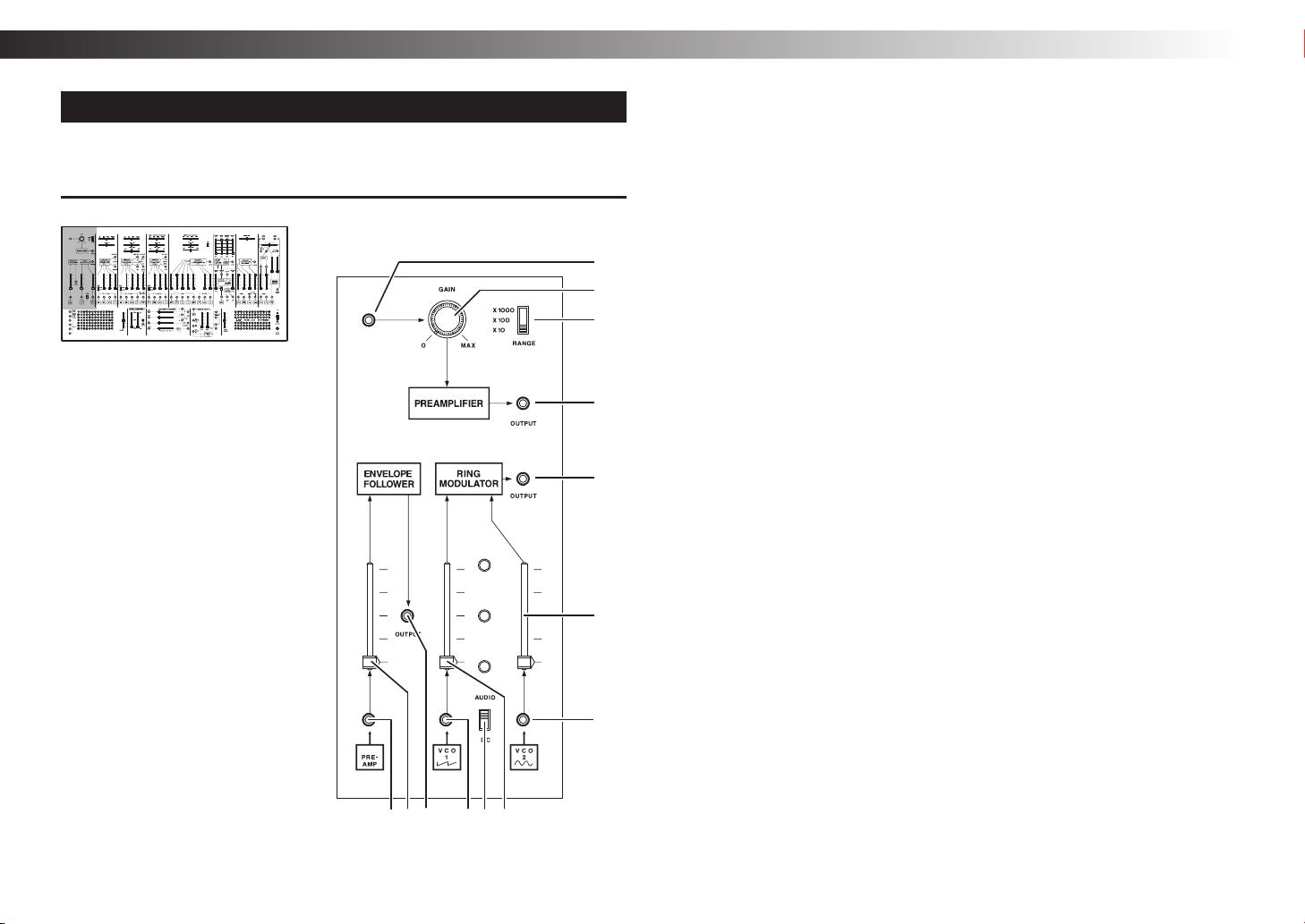
Front panel (PREAMPLIFIER, ENVELOPE FOLLOWER,
RINGMODULATOR section)
INITIAL OSCILLATOR FREQUENCY INITIAL OSCILLATOR FREQUENCY
f g h ie j
a
b
c
d
m
l
k
PREAMPLIFIER
a. Input jack
Inputs an audio signal from a mic, electric guitar, or other source.
b. GAIN knob ............................................................................................ [0…MAX]
Adjusts the gain of the preamp.
c. RANGE switch......................................................................... [x10, x100, x1000]
Switches the amplification ratio of the preamp.
d. Output jack
Outputs the signal that is amplified by the preamp.
ENVELOPE FOLLOWER
e. Input jack
This jack inputs a signal to the envelope follower.
The preamp output is internally connected.
f. Input level slider
Adjusts the signal level that is input to the envelope follower.
g. Output jack
This is the output jack of the envelope follower. It outputs a contour of the input signal.
RING MODULATOR
h. Input 1 jack
This jack inputs the first signal to the ring modulator.
The sawtooth wave of VCO-1 is internally connected.
i. Input select switch ........................................................................... [AUDIO, DC]
Setting this switch to AUDIO will cut the DC offset of the input signal.
If this switch is set to DC, the input signal is passed without modification to the
ring modulator. Choose this setting when inputting a CV.
j. Input level 1 slider
Adjusts the signal level of the input 1 jack. The sawtooth wave of VCO-1 is
internally connected.
k. Input 2 jack
This jack inputs the second signal to the ring modulator.
The sine wave of VCO-2 is internally connected.
l. Input level 2 slider
Adjusts the signal level of the input 2 jack.
m. Output jack
This is the ring modulator’s output jack. It outputs a signal produced by
multiplying two inputs.
- 6 -
Page 7

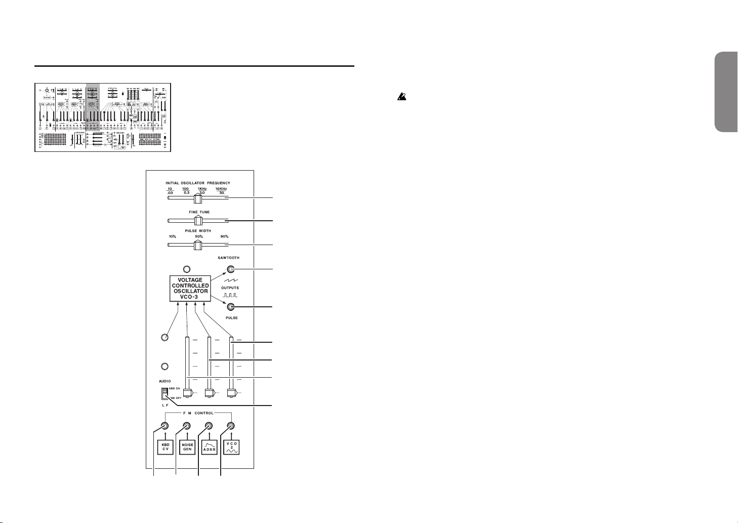
Front panel (VCO-1 section)
INITIAL OSCILLATOR FREQUENCY INITIAL OSCILLATOR FREQUENCY
VCO-1 (Voltage Controlled Oscilator 1)
a. INITIAL OSCILLATOR FREQUENCY slider ...................[10(.03)Hz…10K(30.)Hz]
Broadly adjusts the VCO-1 pitch.
The frequency range is an approximate value.
b. FINE TUNE slider
Finely adjusts the VCO-1 pitch.
a
b
k
l
j
i
h
g
c. CV input 1 jack
This is the pitch CV input jack for VCO-1. The KBD CV is internally connected.
d. CV input 2 jack
This is the pitch CV input jack for VCO-1. The S/H OUT is internally connected.
e. CV input 3 jack
This is the pitch CV input jack for VCO-1. The ADSR is internally connected.
f. CV input 4 jack
This is the pitch CV input jack for VCO-1. The sine wave of VCO-2 is internally
connected.
g. AUDIO/LF select switch ....................................................... [KBD ON, KBD OFF]
Selects whether to use VCO-1 as an audio signal or as an LFO. When used as an
LFO (KBD OFF), the CV from the keyboard is no longer input to VCO-1.
h. CV input 2 slider
Adjusts the signal level of VCO-1 CV input 2.
i. CV input 3 slider
Adjusts the signal level of VCO-1 CV input 3.
j. CV input 4 slider
Adjusts the signal level of VCO-1 CV input 4.
k. SAWTOOTH output jack
Outputs the sawtooth wave of VCO-1.
l. SQUARE output jack
Outputs the square wave of VCO-1.
Owner’s manual
c
d
e
f
- 7 -
Page 8

ARP 2600 FS
Front panel (VCO-2 section)
INITIAL OSCILLATOR FREQUENCY INITIAL OSCILLATOR FREQUENCY
VCO-2 (Voltage Controlled Oscilator 2)
a. INITIAL OSCILLATOR FREQUENCY
slider
...... [10(.03)Hz…10K(30.)Hz]
Broadly adjusts the VCO-2 pitch.
The frequency range is an
approximate value.
a
b
c
n
o
p
q
m
l
k
j
i
d
e
g
f h
b. FINE TUNE slider
Finely adjusts the VCO-2 pitch.
c. PULSE WIDTH slider
................................... [10%…90%]
Adjusts the duty cycle of the VCO-2
pulse wave.
d. CV input 1 jack
This is the pitch CV input jack for
VCO-2. The KBD CV is internally
connected.
e. CV input 2 jack
This is the pitch CV input jack for
VCO-2. The S/H OUT is internally
connected.
f. CV input 3 jack
This is the pitch CV input jack for
VCO-2. The ADSR is internally
connected.
g. CV input 4 jack
This is the pitch CV input jack for
VCO-2. The pulse wave of VCO-1 is
internally connected.
h. PULSE WIDTH MODULATION
input jack
This is the input jack for the CV that
controls the duty cycle of the
VCO-2 pulse wave output. The
noise generator is internally
connected.
i. AUDIO/LF select switch
........................[KBD ON, KBD OFF]
Selects whether to use VCO-2 as an
audio signal or as an LFO. When
used as an LFO (KBD OFF), the
CV from the keyboard is no longer
input to VCO-2.
j. CV input level 2 slider
Adjusts the signal level of VCO-2
CV input 2.
k. CV input level 3 slider
Adjusts the signal level of VCO-2
CV input 3.
l. CV input level 4 slider
Adjusts the signal level of VCO-2
CV input 4.
m. PULSE WIDTH MODULATION
input level slider
Adjusts the amount of pulse width
modulation.
n. TRIANGLE output jack
Outputs the triangle wave of VCO-2.
o. SAWTOOTH output jack
Outputs the sawtooth wave of
VCO-2.
p. PULSE output jack
Outputs the pulse wave of VCO-2.
q. SINE output jack
Outputs the sine wave of VCO-2.
- 8 -
Page 9
Front panel (VCO-3 section)
INITIAL OSCILLATOR FREQUENCY INITIAL OSCILLATOR FREQUENCY
m
k
j
i
h
VCO-3 (Voltage Controlled Oscilator 3)
a. INITIAL OSCILLATOR FREQUENCY slider ...................[10(.03)Hz…10K(30.)Hz]
Broadly adjusts the VCO-3 pitch.
The frequency range is an approximate value.
b. FINE TUNE slider
Finely adjusts the VCO-3 pitch.
c. PULSE WIDTH slider ....................................................................... [10%…90%]
Adjusts the duty cycle of the VCO-3 pulse wave.
d. CV input 1 jack
This is the pitch CV input jack for VCO-3. The KBD CV is internally connected.
e. CV input 2 jack
a
b
c
l
This is the pitch CV input jack for VCO-3. The noise generator is internally
connected.
f. CV input 3 jack
This is the pitch CV input jack for VCO-3. The ADSR is internally connected.
g. CV input 4 jack
This is the pitch CV input jack for VCO-3. The sine wave of VCO-2 is internally
connected.
h. AUDIO/LF select switch ....................................................... [KBD ON, KBD OFF]
Selects whether to use VCO-3 as an audio signal or as an LFO. When used as an
LFO (KBD OFF), the CV from the keyboard is no longer input to VCO-3.
i. CV input level 2 slider
Adjusts the signal level of VCO-3 CV input 2.
j. CV input level 3 slider
Adjusts the signal level of VCO-3 CV input 3.
k. CV input level 4 slider
Adjusts the signal level of VCO-3 CV input 4.
l. SAWTOOTH output jack
Outputs the sawtooth wave of VCO-3.
m. PULSE output jack
Outputs the pulse wave of VCO-3.
Owner’s manual
e
d
f
g
- 9 -
Page 10
ARP 2600 FS
Front panel (VCF section)
INITIAL OSCILLATOR FREQUENCY INITIAL OSCILLATOR FREQUENCY
e
g
f
h
i j k l
a
b
d
c
t
s
q
p
o
n
m
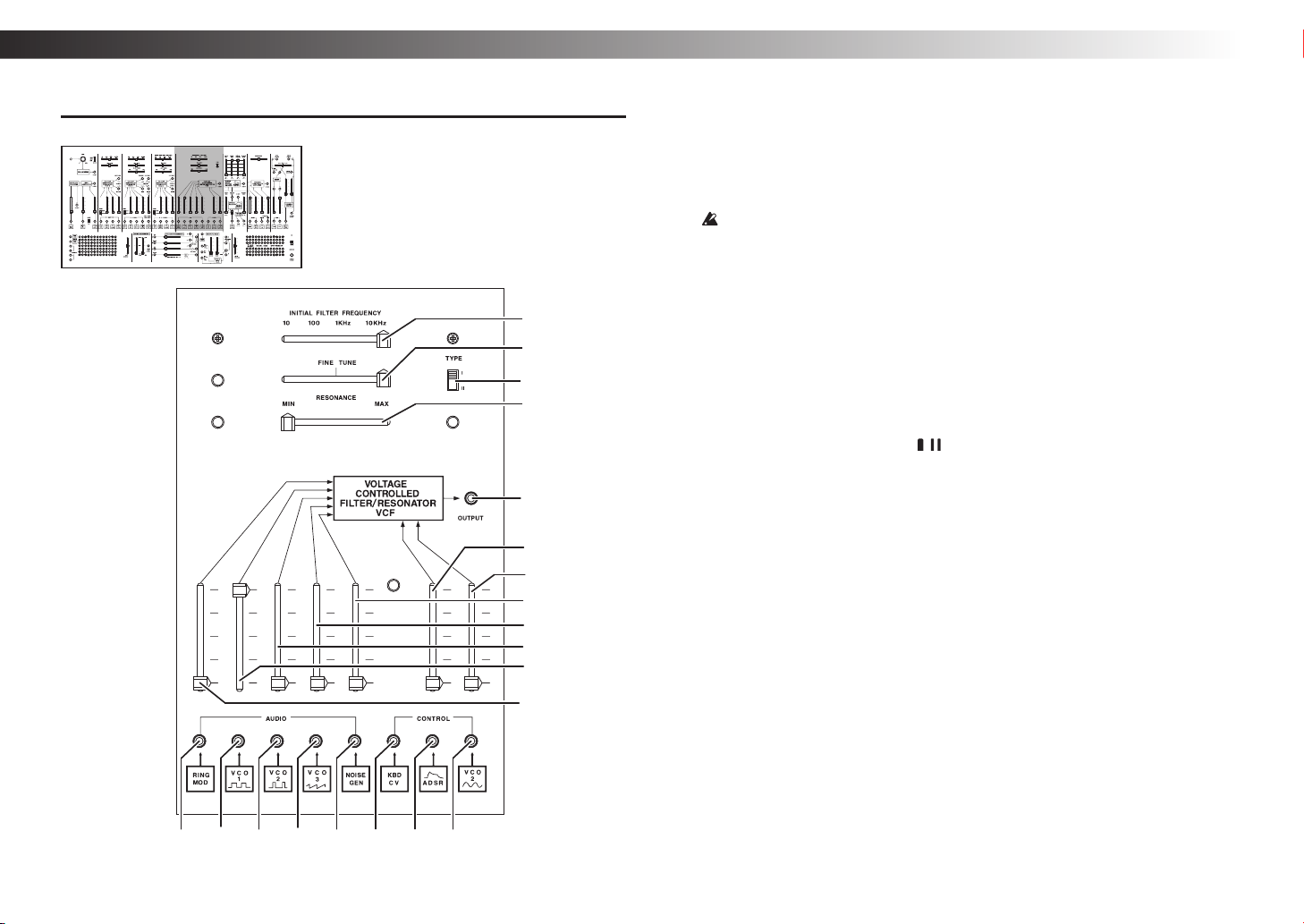
VCF (Voltage Controlled Filter)
a. INITIAL FILTER FREQUENCY slider ............................................ [10Hz…10KHz]
Broadly adjusts the cutoff frequency of the LPF (low-pass filter).
Moving the slider toward the left cuts the high-frequency range of the input
signal, producing a softer tone. Moving the slider toward the right produces a
harder and brighter tone.
The frequency range is an approximate value.
b. FINE TUNE slider
Finely adjusts the cutoff frequency
of the LPF.
c. RESONANCE slider
Adjusts the filter resonance level.
This modifies the tonal character by
boosting the overtones in the region
of the cutoff point. As you raise the
slider, self-oscillation (a state in which
the VCF itself produces a sound) will
occur starting at a certain point.
d. TYPE switch ............................ [ , ]
Selects the type of VCF.
TYPE I: ARP 2600 early models
TYPE II: ARP 2600 late models
e. AUDIO input 1 jack
r
This is the input jack for the VCF
audio signal. RING MODULATOR
is internally connected.
f. AUDIO input 2 jack
This is the input jack for the VCF
audio signal. The square wave of
VCO-1 is internally connected.
g. AUDIO input 3 jack
This is the input jack for the VCF
audio signal. The pulse wave of
VCO-2 is internally connected.
h. AUDIO input 4 jack
This is the input jack for the VCF
audio signal. The sawtooth wave of
VCO-3 is internally connected.
i. AUDIO input 5 jack
This is the input jack for the VCF
audio signal. The noise generator is
internally connected.
j. CV input 1 jack
This is a CV input jack that controls
the VCF cutoff frequency. The KBD
CV is internally connected.
k. CV input 2 jack
This is a CV input jack that controls
the VCF cutoff frequency. The
ADSR is internally connected.
l. CV input 3 jack
This is a CV input jack that controls
the VCF cutoff frequency. The sine
wave of VCO-2 is internally connected.
m. AUDIO input level 1 slider
Adjusts the audio signal level of
VCF AUDIO input 1.
n. AUDIO input level 2 slider
Adjusts the audio signal level of
VCF AUDIO input 2.
o. AUDIO input level 3 slider
Adjusts the audio signal level of
VCF AUDIO input 3.
p. AUDIO input level 4 slider
Adjusts the audio signal level of
VCF AUDIO input 4.
q. AUDIO input level 5 slider
Adjusts the audio signal level of
VCF AUDIO input 5.
r. CV input level 2 slider
Adjusts the signal level of VCF CV
input 2.
s. CV input level 3 slider
Adjusts the signal level of VCF CV
input 3.
t. Output jack
This is the VCF output jack.
- 10 -
Page 11
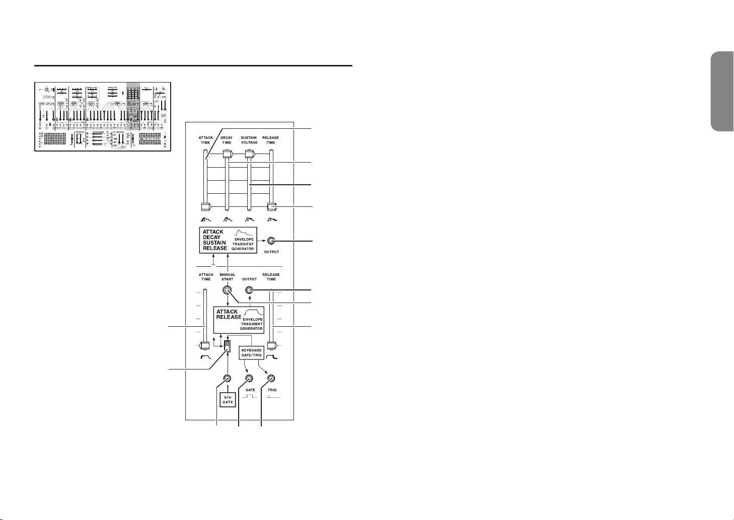
Front panel (ADSR EG/AR EG section)
INITIAL OSCILLATOR FREQUENCY INITIAL OSCILLATOR FREQUENCY
ADSR EG (Envelope generator)
a. ATTACK TIME slider
Adjusts the attack time of the ADSR envelope generator.
b. DECAY TIME slider
Adjusts the decay time of the ADSR envelope generator.
a
b
c
c. SUSTAIN VOLTAGE slider
Adjusts the sustain level of the ADSR envelope generator.
d. RELEASE TIME slider
Adjusts the release time of the ADSR envelope generator.
e. Output jack
This is the output jack of the ADSR envelope generator.
Owner’s manual
d
e
m
l
f
g
h
i
j k
AR EG (Envelope generator)
f. ATTACK TIME slider
Adjusts the attack time of the AR envelope generator.
g. RELEASE TIME slider
Adjusts the release time of the AR envelope generator.
h. GATE/TRIG source select switch ............... [S/H GATE, KEYBOARD GATE/TRIG]
Selects whether the GATE/TRIGGER signal is received from S/H GATE or from
the keyboard.
i. GATE input jack
Inputs the gate signal. S/H GATE is internally connected.
j. GATE output jack
Outputs the gate signal of the keyboard.
k. TRIG output jack
Outputs the trigger signal of the keyboard.
l. MANUAL START switch
Pressing this switch generates a gate signal, outputting an ADSR/AR signal.
This is convenient when you want to audition the sound without using the
keyboard.
m. Output jack
This is the output jack of the AR envelope generator.
- 11 -
Page 12
ARP 2600 FS
INITIAL OSCILLATOR FREQUENCY INITIAL OSCILLATOR FREQUENCY
a
b
j
f
g
h
i
c
d e
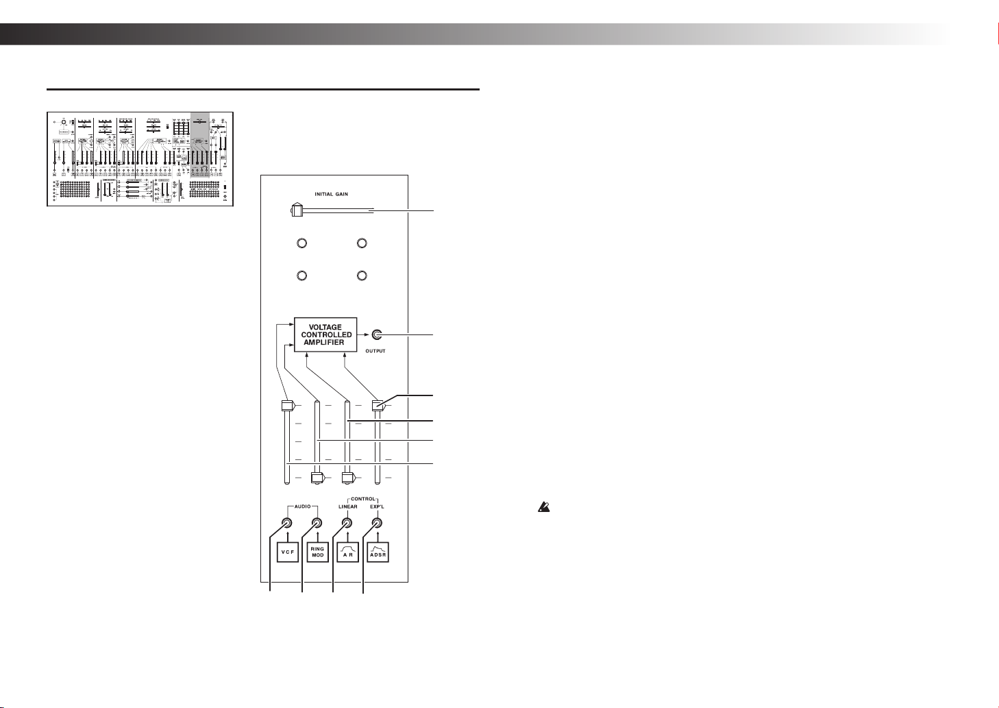
Front panel (VCA section)
VCA (Voltage Controlled Amplifier)
a. INITIAL GAIN slider
Adjusts the CV offset voltage of the VCA.
b. AUDIO input 1 jack
This is the input jack for the VCA audio signal. The VCF is internally connected.
c. AUDIO input 2 jack
This is the input jack for the VCA audio signal. The ring modulator is internally
connected.
d. CV input 1 jack
This is the CV input jack that controls the VCA gain. The AR EG is internally
connected.
The VCA gain is proportionally related to this CV voltage.
e. CV input 2 jack
This is the CV input jack that controls the VCA output. The ADSR EG is
internally connected.
The VCA gain is exponentially related to this CV voltage.
f. AUDIO input level 1 slider
Adjusts the audio signal level of VCA AUDIO input 1.
g. AUDIO input level 2 slider
Adjusts the audio signal level of VCA AUDIO input 2.
h. CV input level 1 slider
Adjusts the signal level of VCA CV input 1.
i. CV input level 2 slider
Adjusts the signal level of VCA CV input 2.
j. Output jack
This is the VCA output jack. It outputs an audio signal whose volume varies
according to the CV signals from CV input 1 and CV input 2.
If the INITIAL GAIN slider (a) is moved all the way to the right, the audio
signal is output continuously without stopping.
- 12 -
Page 13

Front panel (MIXER, REVERB section)
INITIAL OSCILLATOR FREQUENCY INITIAL OSCILLATOR FREQUENCY
i
g
f
e
d
c
a
b
m
MIXER
a. Input 1 jack
This is the mixer input jack. The
VCF output is internally connected.
b. Input 2 jack
j
l
h
k
o
n
p
This is the mixer input jack. The
VCA output is internally connected.
c. Input level 1 slider
Adjusts the audio signal level of
mixer input 1.
d. Input level 2 slider
Adjusts the audio signal level of
mixer input 2.
e. Audio output 1 jack
This jack outputs an audio signal
that is adjusted by c. Input level 1
slider.
f. Audio output 2 jack
This jack outputs an audio signal
that is adjusted by d. Input level 2
slider.
g. L/R input jack
This is an input for the audio signal
that is output to both the left and
right channels. The mixer output is
internally connected.
h. PAN slider
Adjusts the panpot (left/right
volume balance).
i. LEFT INPUT jack
This is the input jack for the left
channel of the mixer.
j. LEFT OUTPUT jack
This jack outputs an audio signal
that sums the output of the spring
reverb adjusted by n. with the input
from the LEFT INPUT jack.
k. RIGHT INPUT jack
This is the input jack for the right
channel of the mixer.
l. RIGHT OUTPUT jack
This jack outputs an audio signal
that sums the output of the spring
reverb adjusted by o. with the input
from the RIGHT INPUT jack.
REVERB
m. Input jack
This is the input jack for the
spring reverb. The mixer output is
internally connected.
n. Level slider L
Adjusts the level of the LEFT signal
that is input to the spring reverb.
o. Level slider R
Adjusts the level of the RIGHT
signal that is input to the spring
reverb.
p. REVERB OUTPUT jack
This is the output of the spring
reverb. If a patch cable is connected
here, the reverberated signal from l.
is no longer output.
Owner’s manual
- 13 -
Page 14
ARP 2600 FS
Front panel (NOISE GENERATOR, VOLTAGE PROCESSORS section)
INITIAL OSCILLATOR FREQUENCY INITIAL OSCILLATOR FREQUENCY
d
g
j
a b c
e
o
f
h
l
m
i
p
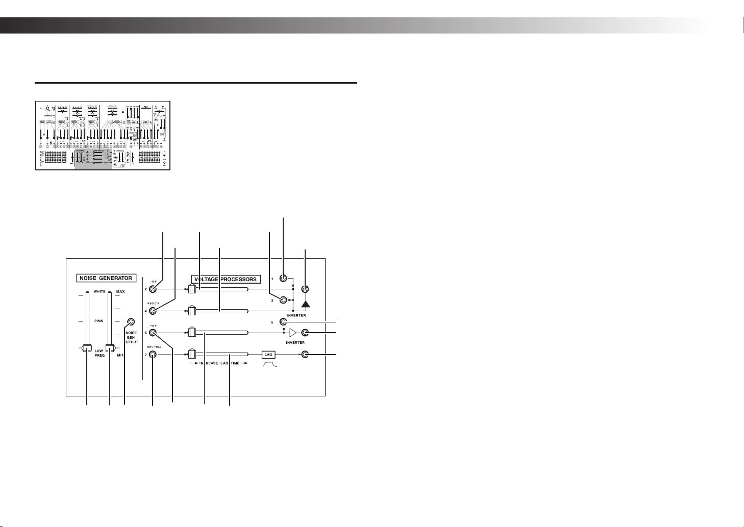
NOISE GENERATOR
a. Noise color slider
...........[LOW FREQ...PINK...WHITE]
Adjusts the frequency components
of the noise.
b. Noise level slider
Adjusts the signal level of the noise
generator.
c. NOISE GEN OUTPUT jack
This is the output jack of the noise
generator.
VOLTAGE PROCESSORS
d. Inverter input 1 jack
This is an input jack for an inverter
(a module that inverts a voltage).
e. Inverter input 2 jack
This is an input jack for an inverter.
−10 V is internally connected.
f. Inverter input 2 level slider
Adjusts the voltage level of the
inverter input 2 jack.
k
n
q
g. Inverter input 3 jack
This is an input jack for an inverter.
h. Inverter input 4 jack
This is an input jack for an inverter.
KBD CV is internally connected.
If you patch an inverted KBD CV
Tip:
to a VCO, the relationship between
the keyboard and the pitch is
reversed.
i. Inverter input 4 level slider
Adjusts the voltage level of the
inverter input 4 jack.
j. Inverter output 1 jack
Outputs an inverted summed
voltage of inverter inputs 1–4.
k. Inverter input 5 jack
This is an input jack for an inverter.
l. Inverter input 6 jack
This is an input jack for an inverter.
+10 V is internally connected.
m. Inverter input 6 level slider
Adjusts the voltage level of the
inverter input 6 jack.
n. Inverter output 2 jack
Outputs an inverted summed
voltage of inverter inputs 5 and 6.
o. LAG input jack
This is an input jack for the lag
(delay) circuit. The output of the
envelope follower (see “ENVELOPE
FOLLOWER” on page 6) is
internally connected.
p. LAG TIME slider
Adjusts the length of lag time.
Sliding this toward the right
smooths the output signal.
q. LAG output jack
Outputs a signal smoothed by the
lag circuit.
- 14 -
Page 15
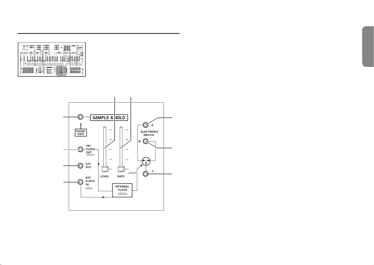
Front panel (SAMPLE & HOLD section)
INITIAL OSCILLATOR FREQUENCY INITIAL OSCILLATOR FREQUENCY
e f
a
b
c
d
SAMPLE & HOLD
a. SAMPLE & HOLD input jack
This is the input jack for the sample & hold circuit. The noise generator is
internally connected.
b. INT CLOCK OUT jack
Outputs the clock signal of the clock generator built into this unit.
c. S/H OUT jack
Outputs the sample & hold signal.
d. EXT CLOCK IN jack
This is an input jack for an external clock. If a clock signal is input from an
external device to this jack, the SAMPLE & HOLD and ELECTRONIC SWITCH
will synchronize to the external clock.
e. Sample & hold input level slider
Adjusts the level of the signal that is input to the sample & hold circuit.
g
h
i
f. CLOCK RATE slider ........................................................................ [0.2Hz...24Hz]
Adjusts the frequency of the internal clock.
g. ELECTRONIC SWITCH A jack
This is an analog switch that synchronizes to the clock. ELECTRONIC SWITCH
B and C are used together.
h. ELECTRONIC SWITCH B jack
This is an analog switch that synchronizes to the clock. ELECTRONIC SWITCH
A and C are used together.
i. ELECTRONIC SWITCH C jack
This is an analog switch that synchronizes to the clock. ELECTRONIC SWITCH
A and B are used together. Jacks A-C and jacks B-C are alternately connected in
synchronization with the clock.
For example if jack A is connected to LEFT INPUT, jack B is connected to
Tip:
RIGHT INPUT, and jack C is connected to an audio signal, an auto-pan effect is
obtained.
Owner’s manual
- 15 -
Page 16
ARP 2600 FS
a
b
c
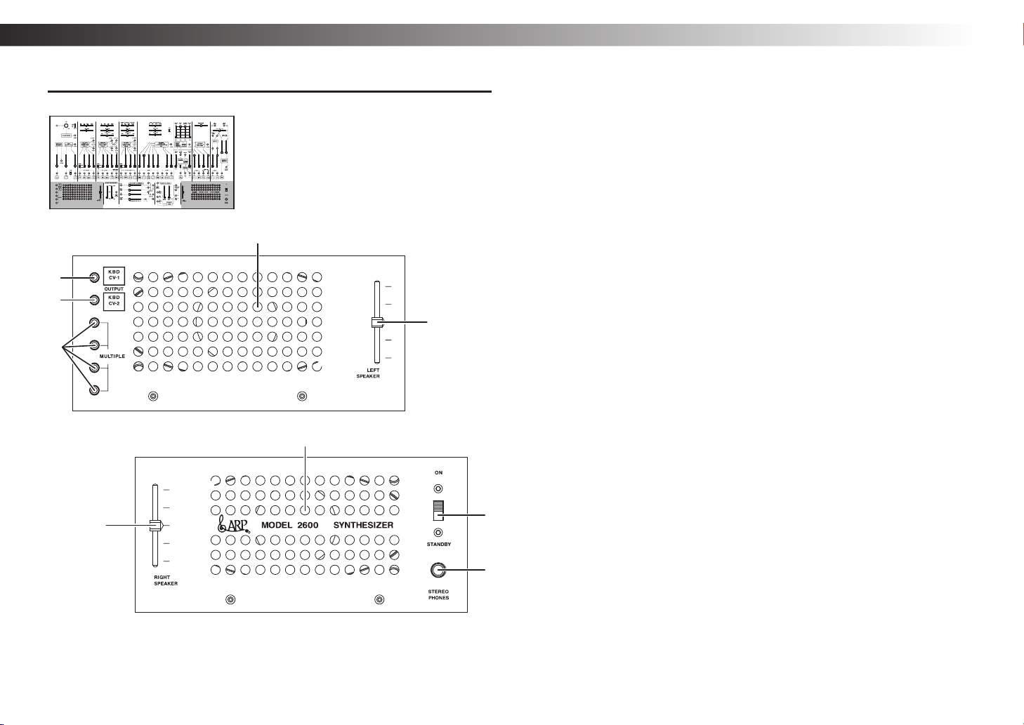
Front panel (SPEAKER section L, SPEAKER section R)
INITIAL OSCILLATOR FREQUENCY INITIAL OSCILLATOR FREQUENCY
d
e
SPEAKER section L
a. KBD CV-1 jack
Outputs a pitch CV when a key is pressed on the ARP 3620 keyboard. If two
keys are pressed, the pitch CV of the lower key is output.
The KBD CV input voltage of a VCO or the VCF is the same as the output
Tip:
voltage of this KBD CV-1 jack.
b. KBD CV-2 jack
Outputs a pitch CV when a key is pressed on the ARP 3620 keyboard. If two
keys are pressed, the pitch CV of the higher key is output.
The UPPER VOICE output voltage of the ARP 3620 keyboard unit is the same
Tip:
as the output voltage of this KBD CV-2 jack.
For details on the pitch CV voltage when multiple keys are pressed, refer to
Tip:
“Voice assign mode settings” on page 23.
c. MULTIPLE jacks
These are general-purpose signal distribution jacks (paralleled) that can be used
for either audio signals or control signals.
d. Internal speaker L
e. LEFT SPEAKER slider
Adjusts the volume of internal speaker L.
g
f
h
SPEAKER section R
f. RIGHT SPEAKER slider
Adjusts the volume of internal speaker R.
g. Internal speaker R
h. Power switch
This turns the power on/off.
i. STEREO PHONES jack
Connect your headphones here. This is a φ6.3 mm (1/4") stereo phone jack.
i
- 16 -
Page 17
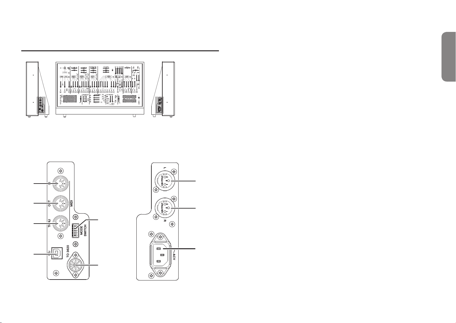
Side panel L (MIDI, USB, MODE SWITCH) Side panel R (power, main output jacks)
INITIAL OSCILLATOR FREQUENCY INITIAL OSCILLATOR FREQUENCY
a
g
MIDI
a. MIDI IN connector
You can connect an external MIDI device to this connector to receive MIDI data.
b. MIDI OUT connector
You can connect an external MIDI device to this connector to transmit MIDI
data.
c. MIDI THRU connector
The MIDI messages that are input via the MIDI IN connector are output without
change from this connector.
USB
d. USB B port
You can connect a computer to this port to transmit and receive MIDI data.
MODE SWITCH
This switch lets you set the MIDI channel and the auto power-off setting.
e. MODE SWITCH1–5
The combination of switches 1–4 specifies MIDI channel 1–16 (see “MIDI
channel” on page 24). Switch 5 enables or disables the auto power-off
function. (see
f. TO 3620 connector
Use the included 8-pin DIN cable to connect this to the ARP 3620 keyboard unit.
“Changing the auto power-off setting” on page 21).
Owner’s manual
b
c
d
e
Main output jacks
h
i
f
g. Main output L
Outputs the L channel audio signal of this unit. This is an XLR connector
(balanced). 1: GND, 2: HOT, 3: COLD
h. Main output R
Outputs the R channel audio signal of this unit. This is an XLR connector
(balanced). 1: GND, 2: HOT, 3: COLD
Power connector
i. ~ ACV connector
Connect the included AC power cord here.
- 17 -
Page 18
ARP 2600 FS
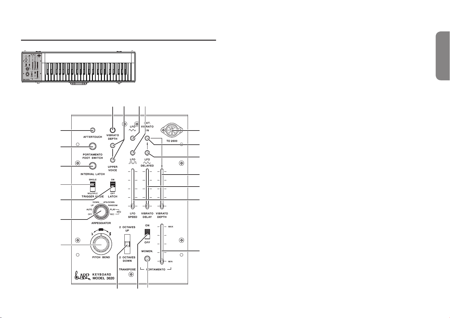
ARP3620 keyboard unit
a
b
c
d
e
f
g
h
ARP3620 keyboard unit
a. AFTERTOUCH output jack
Outputs a CV signal according
to the force that you apply to the
keyboard via aftertouch.
b. PORTAMENTO FOOT SWITCH jack
If you want to use a separately sold
foot switch (such as the Korg PS-1)
to control portamento, connect it
p
o
ml
u
s
r
t
q
n
k
i
j
here.
c. INTERVAL LATCH jack
Connect a separately sold foot
switch (such as the Korg PS-1)
here. If you turn on the foot switch
while holding down two keys, the
interval between the two keys is
memorized. While the foot switch is
on, pressing one key causes a note
higher by the memorized interval
(the CV signal) to be output from
the UPPER VOICE output jacks.
d. TRIGGER MODE switch
....................... [SINGLE/MULTIPLE]
Selects how the ADSR circuit starts
operating (is triggered) when
consecutive note-on occurs.
SINGLE: Since a new note-on will
not cause a trigger until the ADSR
release time has ended, this is used
for legato performance.
MULTIPLE: The ADSR circuit is
triggered by each note-on.
TRIGGER MODE does not
apply to the AR circuit.
e. LATCH switch .................. [ON/OFF]
If this switch is on, and you take
your finger off a key after playing
it, the state is maintained (the note
is latched) until the next time you
press a key. This is used mainly
in conjunction with the internal
arpeggiator.
f. ARPEGGIATOR selector
.......................... [OFF/AUTO...SEQ]
Selects the type for the internal
arpeggiator. The arpeggiator tempo
is synchronized with the LFO
speed.
OFF: Choose OFF if you are not
using the internal arpeggiator.
AUTO: If two or more keys are held
down, they sound in the order in
which they were pressed.
UP: While two or more keys are
held down, they sound in order
from the lower to the higher.
DOWN: While two or more keys are
held down, they sound in order
from the higher to the lower.
UP&DOWN: UP and DOWN
alternate repeatedly.
RANDOM: While two or more keys
are held down, they are sounded
randomly.
SEQ PLAY: Keys are sounded in
the pattern that you previously
recorded using SEQ REC. In
advance, choose SEQ REC and
record an arpeggio pattern.
SEQ REC: When SEQ REC is
selected, pitches are recorded in the
order in which you play the keys.
To use the arpeggio pattern that
you recorded, switch to SEQ PLAY.
For more about the internal
Tip:
arpeggiator, refer to “Arpeggiator
settings” on page 23.
- 18 -
Page 19
ARP3620 keyboard unit
a
b
c
d
e
f
g
h
g. PITCH BEND control
Raises or lowers the pitch of the
currently sounding note in real
time. The pitch will change in a
range of ±1 octave.
h. TRANSPOSE switch
Switches the range of the entire
keyboard unit up or down in twooctave units.
i. PORTAMENTO switch
p
o
ml
u
s
r
t
q
n
k
i
j
Switches the portamento effect on/
off.
j. PORTAMENTO momentary switch
The portamento effect turns on only
while you hold down this switch.
This switch is effective even if i.
Tip:
PORTAMENTO switch is off.
k. PORTAMENTO slider
......................... [MIN(OFF), ...MAX]
Specifies the portamento time
(the time over which the pitch
transitions to the next note). If the
slider is in the “MIN” position, no
portamento effect is applied.
l. VIBRATO DEPTH control
Adjusts the depth of the vibrato
effect applied by aftertouch.
m. UPPER VOICE output jacks
Output a CV voltage corresponding
to the highest key when you play
multiple keys. There are two
identical jacks, and each can be
patched to a VCO, etc.
For details on the pitch CV voltage
Tip:
when multiple keys are pressed,
refer to “Voice assign mode
settings” on page 23.
n. LFO SPEED slider
Adjusts the frequency of the
internal LFO.
This slider applies to all of the
LFOs: triangle wave, square wave,
and sine wave.
o. Triangle wave LFO output jack
Outputs a triangle wave LFO. This
can be used simultaneously with p.
Square wave LFO.
p. Square wave LFO output jack
Outputs a square wave LFO. This
can be used simultaneously with o.
Triangle wave LFO.
q. VIBRATO DELAY slider
Adjusts the delay time when you
want the sine wave LFO to start a
fixed time after the note begins. If
this is at the minimum setting, the
sine wave LFO starts the moment
that the note begins.
r. Sine wave LFO output jack
Outputs a sine wave LFO. This LFO
is delayed after the beginning of the
note by the length of time specified
by the VIBRATO DELAY slider.
s. EXT.VIBRATO IN jack
Use this if you want vibrato to be
controlled by an external signal
t. VIBRATO DEPTH slider
Adjusts the depth of the vibrato
effect produced by the LFO. This
slider applies to all of the LFOs:
triangle wave, square wave, and
sine wave.
u. TO 2600 connector
Use the included 8-pin DIN cable
to connect this to the ARP 2600 FS
main unit.
Owner’s manual
- 19 -
Page 20
ARP 2600 FS
Getting started
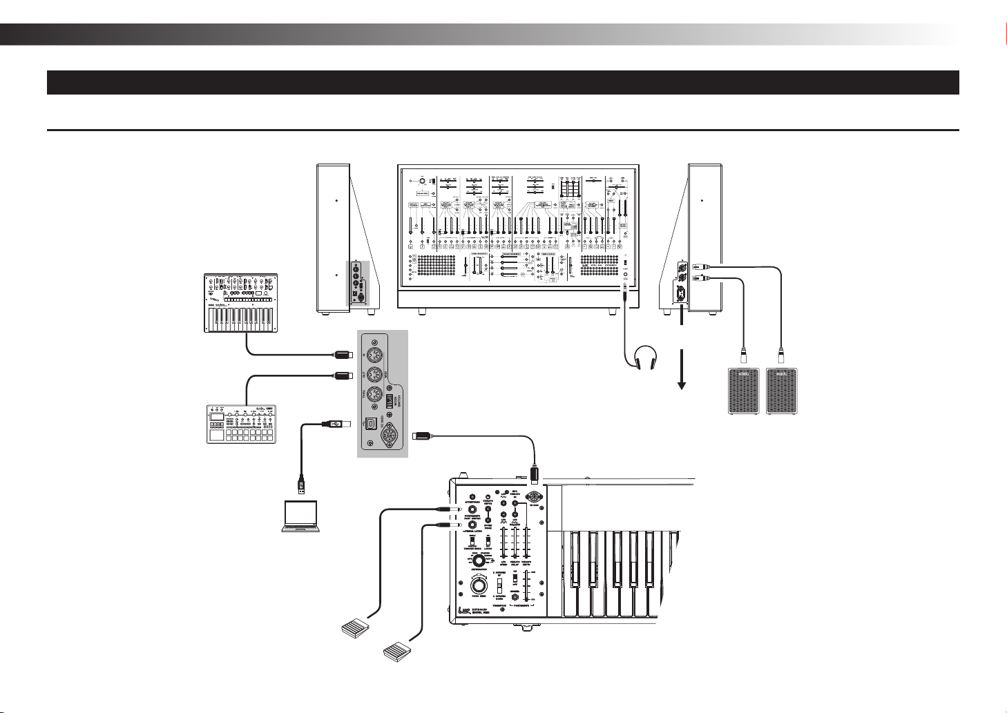
Connections
The following illustration shows an example of typical connections. Connect your equipment as appropriate for your needs.
INITIAL OSCILLATOR FREQUENCY INITIAL OSCILLATOR FREQUENCY
MIDI Keyboard,
Rhythm machine, etc.
MIDI OUT
MIDI IN
Sound module,
Rhythm machine, etc.
USB cable
Computer
KORG PS-1/PS-3
Pedal Switch
(Sold separately)
KORG PS-1/PS-3
(Sold separately)
Pedal Switch
ARP 2600 FS
8 pin DIN cable (included)
ARP 3620 Keyboard Unit
* Use only the included
8-pin DIN cable.
Headphones
Power cord
(included)
to AC outlet
XLR cable
Powered Monitor
- 20 -
Page 21
Turning the power on
Turn off the power of your powered monitor speakers or other external output
device before you power-on the ARP 2600 FS.
1. Lower this unit’s LEFT SPEAKER slider and RIGHT SPEAKER slider to the
minimum position.
2. When you turn this unit’s power switch ON, the power supply LED is lit, and
the power turns on. Lower the volume of your powered monitors or other
external output equipment before you turn the power on.
3. Adjust this unit’s LEFT SPEAKER slider and RIGHT SPEAKER slider. If
external output equipment is connected, raise the volume of that equipment as
appropriate.
If you are not familiar with how to create sounds, we suggest that you now
Tip:
adjust the settings as described in the “Basic settings” section.
Turning the power off
1. Lower the volume of your powered monitors or external output system, and
turn their power off.
2. When you set this unit’s power switch to the STANDBY position, the power
supply LED goes dark, and the power turns off.
Auto power-off function
The ARP 2600 FS has an auto power-off function that automatically turns the power
off when approximately four hours have elapsed since the instrument was last
played or used. With the factory settings, the auto power-off function is enabled.
Owner’s manual
Changing the auto power-off setting
If desired, you can enable or disable the auto power-off function.
Disabling the auto power-off function
On side panel L, set MODE SWITCH 5 off (downward
position). The auto power-off function is disabled; you don’t
have to turn the power off and on again to apply the setting.
Enabling the auto power-off function
On side panel L, set MODE SWITCH 5 on (upward position).
The auto power-off function is enabled; you don’t have to turn
the power off and on again to apply the setting.
ON
1 2 3 4
ON
1 2 3 4
5
5
- 21 -
Page 22

ARP 2600 FS
Let’s make some sounds
Basic settings
Set the ARP 2600 FS’s controls (sliders, switches, etc.) as shown in the illustration below.
When you play the keyboard with these settings, the sound of the VCO-1 square
wave is output by itself. To adjust the volume, use the MIXER section’s input level 2
slider (see
“MIXER” on page 13).
When you use a patch cable to connect the ARP 2600 FS unit with the ARP 3620
keyboard unit, the difference in GND level (the discrepancy in reference
voltage) might cause the pitch to drift by several cents.
Tuning
After you set this unit to the basic settings
described previously, adjust the FINE TUNE
slider of each VCO to the correct pitch using a
commercially available tuner (such as the Korg
CA-50).
- 22 -
Page 23
Arpeggiator settings
The ARP 3620 keyboard unit is equipped with an internal arpeggiator.
When you hold down two or more keys, the arpeggiator plays an arpeggio (broken
chord) or a previously recorded arpeggio pattern in synchronization with the LFO
tempo. To record and play back an arpeggio pattern, proceed as follows.
Recording an arpeggio pattern (SEQ REC)
1. On the panel of the ARP 3620, set the ARPEGGIATOR selector to “SEQ REC.”
2. When you play the keyboard in this state, notes are recorded as an arpeggio
pattern in the order in which you play them.
When you press and release a key, the arpeggio pattern advances by one step.
Tip:
By pressing the MOMEN.SW while holding down a key, you can enter a tie. By
pressing the MOMEN.SW while not holding down a key, you can enter a rest.
By pressing the MOMEN.SW several times, you can enter the corresponding
Tip:
number of consecutive ties or rests.
The arpeggio pattern is remembered while the power is on, but is lost when
you turn off the power.
Playing back the arpeggio pattern (SEQ PLAY)
1. After you have recorded an arpeggio pattern, set the ARPEGGIATOR selector
to “SEQ PLAY.”
2. When you play the keyboard, the arpeggio pattern is played back based on that
note.
When power is cycled, the SEQ REC memory is cleared, so when the
instrument is turned on, you will have to record a new sequence in order to
play back.
This unit’s arpeggiator starts playing from the beginning of the pattern each
Tip:
time a note-on occurs.
The gate time of the arpeggiator is fixed (50%).
Tip:
Voice assign mode settings
The ARP 3620 keyboard unit will output two pitch CV signals according to your
performance, and these can be used in a variety of ways. These two pitch CV
signals are respectively referred to as KBD CV-1 and KBD CV-2, and are sent via the
DIN cable to the ARP 2600 FS main unit.
KBD CV-1 is the same as “KBD CV” on the ARP 2600 FS main unit’s panel, and
is internally pre-connected to VCO1–3, but KBD CV-2 is located on the panel as a
modulation source that is not internally connected. KBD CV-2 is the same as the
UPPER VOICE output of the ARP 3620 keyboard unit’s panel.
When you press one key, KBD CV-1 and KBD CV-2 output the same voltage, but
when you press two or more keys, these two pitch CV outputs will be different
voltages. This unit lets you switch between using these pitch CV outputs in two
different ways (voice assign modes).
Normal mode (default)
This is the factory-set mode. When two or more keys are pressed simultaneously,
the lowest note is output as KBD CV-1 and the highest note is output as KBD CV-2
(UPPER VOICE). To specify this mode, hold down the three keys C3, D3, and E3
and turn on the power of the ARP 2600 FS main unit.
Original mode
This mode reproduces the operation of the original ARP 3620 keyboard unit. This
is the same as normal mode in that the lowest note is output as KBD CV-1 and the
highest note is output as KBD CV-2 (UPPER VOICE), but differs in that the lowest
note and highest note continue being held until the gate signal turns on (the first
key is played). To specify this mode, hold down the two keys C#3 and D#3, and
turn on the power of the ARP 2600 FS.
After changing this setting, do not turn off the power for several seconds.
Doing so might damage the data, causing malfunctions.
The voice assign mode function setting is remembered even after the power is
Tip:
turned off.
Owner’s manual
- 23 -
Page 24
ARP 2600 FS
34
34
34
34
About MIDI
Connecting MIDI devices
By connecting the ARP 2600 FS to a computer or external MIDI sequencer, you
can control the sound generator of the ARP 2600 FS from an external device. Use a
commercially available MIDI cable to connect the ARP 2600 FS’s MIDI IN connector
to the MIDI OUT connector of your external MIDI device (see “Connections” on
page 20).
MIDI IN connector: This receives MIDI messages from other MIDI devices. Connect
this connector to the MIDI OUT connector of the other device.
Note messages (velocity is ignored) are the only type of MIDI messages that
the ARP 2600 FS can receive via its MIDI IN connector. The range of notes that
can be received is 012 (C0)–127 (G9).
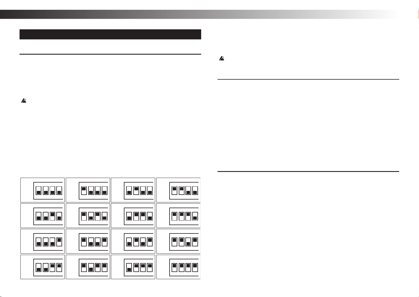
MIDI channel
MIDI has sixteen channels, 1–16.
If you connect an external MIDI device, you must set the MIDI channel of the
ARP 2600 FS to match the MIDI channel of your external MIDI device. With the
factory settings, this is set to channel 1.
For details on how to set the MIDI channel of your external device, refer to its
Tip:
operating manual.
ON
Ch.01
1234
ON
Ch.05
1234
Ch.02
Ch.06
ON
1234
ON
1234
Ch.03
Ch.07
ON
1234
ON
1234
Ch.04
Ch.08
ON
12
ON
12
Setting the MIDI channel of the ARP 2600 FS
Use the rear panel MODE SWITCH 1–4 to specify the MIDI channel. The MIDI
channel settings are shown in the following table. The MIDI channel changes
immediately when you change the setting.
Although you can change the MIDI channel during use, currently-sounding
notes will turn off. Pitch bend is also reset.
Connecting a computer
Use a USB cable to directly connect the ARP 2600 FS to a computer that’s equipped
with a USB port in order to receive MIDI messages in the same way as with the
MIDI connectors (see
“Connections” on page 20).
The only MIDI messages that can be transmitted or received via the USB port are
transmission and reception of note messages (velocity is fixed at 64 for transmission
and ignored for reception) and pitch bend messages (reception only).
The only MIDI messages that are transmitted are note messages transmitted
Tip:
when the keyboard is played. Slider and switch operations do not transmit
MIDI messages.
When connecting via USB, the KORG USB-MIDI driver must be installed.
Tip:
Download the latest version of the KORG USB-MIDI driver from the
Korg website (http://www.korg.com/), and install it as directed by the
documentation included with the driver.
About the MIDI implementation chart
The MIDI implementation chart lists the MIDI messages that can be transmitted
and received. When using a MIDI device, compare the MIDI implementation charts
to check that the MIDI messages are compatible. You can download the MIDI
implementation chart for this device from the Korg website.
Detailed MIDI specifications are provided under MIDI implementation. For
Tip:
more information on MIDI implementation, visit the Korg Web site (http://
www.korg.com/).
Ch.09
Ch.13
ON
1234
ON
1234
Ch.10
Ch.14
ON
1234
ON
1234
Ch.11
Ch.15
ON
1234
ON
1234
Ch.12
Ch.16
ON
12
ON
12
- 24 -
Page 25

Troubleshooting
Specifications
Power won’t turn on.
− Is the AC power cord connected correctly?
No sound.
− Try setting the panel controls to the settings described in the “Basic settings” on
page 22.
− Could the LEFT SPEAKER slider, RIGHT SPEAKER slider (see “Front panel
(SPEAKER section L, SPEAKER section R)” on page 16), the VCA section’s
VCA AUDIO input level 1 slider (see “VCA (Voltage Controlled Amplifier)” on
page 12), the MIXER section’s input level 1 slider, or the input level 2 slider (see
“MIXER” on page 13) be lowered all the way?
− Is the ARP 2600 FS correctly connected to the input jack of your amp, mixer, or
headphones?
− Is your amp or mixer powered-on, and is the volume raided on that device?
− Could the ARPEGGIATOR selector be set to PLAY?
Immediately after the power is turned on and an arpeggio pattern has not yet
been recorded, playing the keyboard will not produce sound (see “Arpeggiator
settings” on page 23).
Does not respond to MIDI data sent from an external device.
− Is the MIDI cable or USB cable connected correctly? (see “Connections” on
page 20)
− Does the MIDI channel of the data being sent from the external MIDI device
match the global MIDI channel of the ARP 2600 FS? (see “MIDI channel” on
page 24)
Can’t input sound from an external audio source.
− Is an external audio source correctly connected to the input jack of
the PREAMPLIFIER section? Also, could the GAIN knob be at 0? (see
“PREAMPLIFIER” on page 6)
− Is the output jack of the PREAMPLIFIER section connected to the audio input of
the VCF or MIXER?
ARP 2600 FS
Operating temperature range: 0 – +40 °C (non-condensing)
Maximum Polyphony: 2 voices for duophonic; normally
monophonic
VCO-1 (Voltage Controlled Oscilator 1)
Waveforms: Sawtooth, square
Frequency range: Approx. 0.03 Hz – 30 Hz (low freq. mode)
Approx. 10 Hz - 10 kHz (audio mode)
Voltage controlled response: 1 V/oct.
VCO-2 (Voltage Controlled Oscilator 2)
Waveforms: Sawtooth, pulse (dynamic pulse), triangle,
sine
Frequency range: Approx. 0.03 Hz - 30 Hz (low freq. mode)
Approx. 10 Hz - 10 kHz (audio mode)
Pulse width: 10% – 90%
Voltage controlled response: 1 V/oct.
VCO-3 (Voltage Controlled Oscilator 3)
Waveforms: Sawtooth, pulse (dynamic pulse)
Frequency range: Approx. 0.03 Hz - 30 Hz (low freq. mode)
Approx. 10 Hz - 10 kHz (audio mode)
Pulse width: 10% – 90%
Voltage controlled response: 1 V/oct.
VCF (Voltage Controlled Filter)
Type: Low-pass (TYPE I : early 24 dB/oct.,
TYPE II: late 24 dB/oct.)
Frequency range: Approx. 10 Hz – 10 kHz
Resonance: 1/2 - self oscillate
VCA (Voltage Controlled Amplifier)
Control voltage: AR type (internally connected)
ADSR type (internally connected)
Noise generator: Noise spectrum types (white and pink)
RING MODULATOR
Type: Analog multiplier
Input signal (Internally connected): VCO-1 sawtooth wave, VCO-2 sine wave
SAMPLE & HOLD
Sampled signal: Noise (internally connected)
Owner’s manual
- 25 -
Page 26

ARP 2600 FS
AUDIO OUTPUT JACKS
Front Panel (LEFT, RIGHT OUTPUT jacks)
Connector: φ3.5 mm monaural phone jack
Maximum output level: +9 dBu @ 10 kΩ load
Output impedance: 1.2 kΩ
Side Panel R
Connector: XLR connector
Maximum output level: +4 dBu @ 600Ω load
Output impedance: 1.2 kΩ
HEADPHONES JACK
Connector: φ6.3 mm stereo phone jack
Maximum output level: 50 mW + 50 mW @ 33Ω load
Output impedance: 20Ω
EXTERNAL AUDIO INPUT (PREAMPLIFIER INPUT) JACK
Connector: φ3.5 mm monaural phone jack
Maximum input level: −10 dBu
Input impedance: 100 kΩ
MIDI connector: IN, OUT, THRU
USB port: Type B
ARP 3620 (keyboard unit)
Keyboard: 49-note (with aftertouch, no velocity
sensitivity)
CV output voltage:
UPPER VOICE −3 V – +10 V, 1 V/oct.
LOWER VOICE −3 V – +7 V, 1 V/oct.
LFO output voltage:
TRIANGLE ±5 V, 10 Vp-p
SQUARE WAVE +10 V, 10 Vp-p
DELAYED SINE WAVE ±3 V, 6 Vp-p
EXTERNAL VIBRATO input voltage: Max. ±10 V
VIBRATO DEPTH slider: Max. 1 octave
VIBRATO DELAY slider: 0 – 2.5 sec
LFO SPEED slider: Approx. 0.25 – 25 Hz
PITCH BEND control: ±1 octave
TRANSPOSE switch: ±2 octave
PORTAMENTO SPEED slider: Maximum speed: about 0.25 msec/oct
Minimum speed: about 0.5 sec/oct
PORTAMENTO foot switch: KORG PS-1/PS-3 pedal switch
INTERVAL foot switch: KORG PS-1/PS-3 pedal switch
GATE output voltage
(on ARP 2600 FS panel): 0 V at all keys up, +10 V at key on
TRIGGER output voltage
(on ARP 2600 FS panel): +10 V, 0.5 ms pulse wave at key on
Arpeggiator: OFF, AUTO, UP, DOWN, UP&DOWN,
RANDOM, SEQ PLAY
General
Power supply: AC power supply terminal
Power consumption: 30 W
Dimensions (W × D × H), Weight:
ARP 2600 FS
ARP 3620 914 × 274 × 158 mm / 36.0 × 10.8 × 6.2 inches,
Included items: Road case, casters (4), AC power cord, 8-pin
Accessories (Sold separately): KORG PS-1/PS-3 pedal switch
* Specifications and appearance are subject to change without notice for
improvement.
836 × 232 × 509 mm / 32.9 × 9.13 × 20.0 inches,
19.3
kg / 42.55 lbs.
11.3 kg / 24.91 lbs.
DIN cable, Mini-phone cable, Owner's
manual, Original English manual (replica)
- 26 -
Page 27
CONSIGNES IMPORTANTES DE SÉCURITÉ
1) Veuillez lire ces consignes.
2) Conservez ces consignes.
3) Tenez compte de tous les avertissements.
4) Suivez toutes les instructions.
5) N’utilisez pas ce produit à proximité d’eau.
6) Nettoyez le produit avec un chiffon sec uniquement.
7) N’obstruez aucun orice d’aération. Installez le produit conformément aux consignes du fabricant.
8) Ne l’installez pas à proximité de sources de chaleur comme des radiateurs, des bouches d’air
chaud, des poêles ou d’autres appareils générateurs de chaleur (amplicateurs compris).
9) Ne supprimez pas la sécurité offerte par la che polarisée ou dotée d’une broche de terre. Une
che polarisée dispose de deux lames dont une plus large que l’autre. Une che avec broche
de terre dispose de deux lames (ou broches) et d’une broche de terre. La lame plus large ou la
troisième broche est conçue pour votre sécurité. Si la che fournie ne s’adapte pas à votre prise
de courant, consultez un électricien pour faire remplacer cette ancienne prise.
10) Protégez le cordon d’alimentation pour éviter qu’il ne soit piétiné ou abîmé notamment à la hau-
teur des ches, des rallonges et au point de connexion du produit.
11) Utilisez exclusivement des xations ou accessoires spéciés par le fabricant.
12) Utilisez cet appareil exclusivement avec un chariot, stand, pied, support ou
table du type spécié par le constructeur ou livré avec l’appareil. Si vous
utilisez un chariot, soyez prudent lors de son déplacement an d’éviter que
le produit ne bascule et ne blesse quelqu’un.
13) Débranchez cet appareil en cas d’orage ou s’il doit rester inutilisé durant
une période assez longue.
14) Pour tout dépannage ou entretien, veuillez consulter un service ou un tech-
nicien qualié. Il est impératif de faire appel à un technicien qualié si l’appareil a été endommagé d’une quelconque façon, notamment, si le cordon d’alimentation ou la che est endomma-
gée, si du liquide s’est renversé ou si des objets sont tombés dans l’appareil, si l’appareil a été
exposé à la pluie ou à l’humidité, s’il ne fonctionne plus normalement ou s’il est tombé.
• AVERTISSEMENT—Ce produit doit être branché à une prise secteur disposant d’une
connexion de sécurité à la terre.
• Un produit branché au secteur ne peut pas être exposé à des gouttes ou des éclaboussures.
Ne placez aucun conteneur de liquide (vase, verre) sur le produit.
• Le fait de couper l’interrupteur n’isole pas complètement le produit de la source de courant.
• Maintenez un accès facile à la prise d’alimentation. N’installez pas ce produit trop loin d’une
prise secteur et/ou d’un multiprise.
• N’installez pas ce produit dans un espace conné comme un ightcase ou autre meuble de ce
type.
• Une pression sonore excessive en provenance d’oreillettes ou d’un casque peut entraîner une
perte auditive.
• Cet instrument est conçu pour être utilisé dans des régions au climat tempéré et ne convient pas
pour les pays au climat tropical.
• Veillez à ne jamais bloquer les orices de ventilation en les couvrant d’objets tels que des
journaux, nappes, rideaux, etc.
• Ne placez aucune source de amme nue, telle qu’une bougie allumée, sur l’instrument.
• L’étiquette signalétique se trouve sur le dessous de l’instrument.
Le symbole d’éclair dans un triangle équilatéral est destiné à avertir l’utilisateur de la
présence d’une tension dangereuse non isolée au sein du produit. Cette tension est
sufsante pour constituer un risque d’électrocution.
Le point d’exclamation dans un triangle équilatéral avertit l’utilisateur de la présence
d’importantes consignes de manipulation ou d’entretien dans la documentation
accompagnant ce produit.
Note concernant les dispositions (Seulement EU)
Quand un symbole avec une poubelle barrée d’une croix apparait sur le produit, le
mode d’emploi, les piles ou le pack de piles, cela signie que ce produit, manuel ou
piles doit être déposé chez un représentant compétent, et non pas dans une
poubelle ou toute autre déchetterie conventionnelle. Disposer de cette manière, de
prévenir les dommages pour la santé humaine et les dommages potentiels pour
l’environnement. La bonne méthode d’élimination dépendra des lois et règlements
applicables dans votre localité, s’il vous plaît, contactez votre organisme administratif pour plus de détails. Si la pile contient des métaux lourds au-delà du seuil
réglementé, un symbole chimique est afché en dessous du symbole de la poubelle barrée
d’une croix sur la pile ou le pack de piles.
* Tous les noms de produits et de sociétés sont des marques commerciales ou déposées de leur
détenteur respectif.
REMARQUE IMPORTANTE POUR LES CLIENTS
Ce produit a été fabriqué suivant des spécications sévères et des besoins en tension
applicables dans le pays où ce produit doit être utilisé. Si vous avez acheté ce produit via
l’internet, par vente par correspondance ou/et vente par téléphone, vous devez vérier que
ce produit est bien utilisable dans le pays où vous résidez.
ATTENTION: L’utilisation de ce produit dans un pays autre que celui pour lequel il a été conçu
peut être dangereuse et annulera la garantie du fabricant ou du distributeur. Conservez bien votre
récépissé qui est la preuve de votre achat, faute de quoi votre produit ne risque de ne plus être
couvert par la garantie du fabricant ou du distributeur.
Manuel d’utilisation
- 27 -
Page 28

ARP 2600 FS
Sommaire
Un mot à propos de l’ARP 2600 FS
Petit historique du synthétiseur
ARP 2600
Caractéristiques principales
Schéma de principe ........ 29
Description des panneaux et
fonctions
Panneau avant (section PREAMPLIFIER,
ENVELOPEFOLLOWER,
RING MODULATOR)
Panneau avant (section VCO-1)
Panneau avant (section VCO-2)
Panneau avant (section VCO-3)
Panneau avant (section VCF)
Panneau avant (section ADSR EG/
AR EG)
Panneau avant (section VCA)
Panneau avant (section MIXER,
REVERB)
Panneau avant (section NOISE
GENERATOR, VOLTAGEPROCESSORS)
. . . . . . . . . . . . . . . . . . . . . . . . . . . . . . . . . . 38
Panneau avant (section SAMPLE &
HOLD)
Panneau avant (section SPEAKER L,
section SPEAKER R)
Panneau latéral G
(MIDI, USB, MODE SWITCH)
Panneau latéral D (alimentation,
prises de sortie principale)
Clavier ARP3620
.............. 28
........................ 28
...... 28
.................30
.............. 30
... 31
... 32
... 33
..... 34
........................... 35
..... 36
......................... 37
........................... 39
.............. 40
....... 41
................. 42
Préparations ..............44
Connexions ...................... 44
Mise sous tension
Mise hors tension
Fonction de mise hors tension
automatique
................ 45
................ 45
..................... 45
Production de sons ........46
Réglages de base ................ 46
Réglage d’accord
Réglages d’arpégiateur
Réglages de mode d’assignation
des voix
......................... 47
................ 46
........... 47
À propos de MIDI ..........48
Connexion de dispositifs MIDI .... 48
Connexion à un ordinateur
À propos du tableau
d’implémentation MIDI
....... 48
. . . . . . . . . . . 48
Dépannage ...............49
Fiche technique
...........49
Un mot à propos de l’ARP 2600 FS
Petit historique du synthétiseur ARP 2600
Produit et vendu entre 1971 et 1981, le synthétiseur ARP 2600 est un des produitsphares d’ARP Instruments, Inc. À l’exception des tout premiers modèles avec
boîtier en métal, le 2600 est célèbre pour sa construction de style valise intégrant un
module de synthé et un module de clavier distincts.
À une époque où les vastes systèmes modulaires étaient encore la norme,
l’ARP 2600 offrait un format de synthétiseur semi modulaire transportable. Les
modules principaux étant pré-connectés en interne, l’instrument permettait de
produire instantanément des sons sans aucun câble, mais aussi de concevoir des
sons extrêmement complexes en connectant des câbles. Vu son riche potentiel de
création sonore, l’ARP 2600 est utilisé par de nombreux artistes lors de sessions
d’enregistrement, mais aussi pour la production de bandes originales de films ainsi
qu’à des fins pédagogiques. Il se distingue aussi par ses haut-parleurs intégrés et sa
réverbération à ressort.
Caractéristiques principales
Synthétiseur ARP 2600 FS
• Doté de VCO, VCF et VCA reposant sur les circuits analogiques de l’ARP 2600
original, cet instrument offre un potentiel de création sonore dépassant de loin
celui des synthés analogiques conventionnels et vous met aux commandes d’une
synthèse flexible et riche en improvisation.
• Les câbles à fiches minijack mono fournis permettent des connexions (alias
‘patching’) ultra-flexibles. Vu que chaque module est connecté en interne à la
sortie d’usine, vous pouvez aussi utiliser l’instrument sans le moindre câble.
• Un sélecteur permet de choisir entre deux types de VCF (anciens modèles et
modèles plus récents).
• L’instrument propose deux types de générateurs d’enveloppe: “ADSR” et “AR”.
• L’entrée pour source audio externe permet d’acheminer et de traiter le son d’une
guitare ou d’un micro, par exemple.
• Le port USB et les prises MIDI permettent de brancher l’instrument à un
ordinateur ou à des dispositifs MIDI.
Clavier ARP 3620
• Le clavier offre trois types de LFO: onde triangulaire, onde carrée et onde
sinusoïdale. Utilisé en conjonction avec le synthétiseur ARP 2600, ce clavier
permet de produire divers effets comme par exemple vibrato et trémolo.
• Il intègre aussi un arpégiateur absent sur l’original permettant d’enregistrer et de
lire des motifs d'arpège.
• Le clavier comporte aussi un détecteur d’aftertouch permettant d’appliquer un vibrato
au son en maintenant la pression sur les touches enfoncées. En outre, en connectant
des câbles, vous pouvez produire divers changements sonores avec l’aftertouch.
- 28 -
Page 29

Schéma de principe
RING
MODULATOR
To MIXER
VCO-1 VCO-2
SAMPLE
&HOLD
INTERNAL
CLOCK
VCF
MIXER
VCA
NOISE
GENERATOR
ELECTRONIC
SWITCH
KEYBOARD
UPPER
CV
REVERB-
ERATOR
VCO-3
ADSR
GATE TRIGGER
MANUAL
START
KEYBOARD
+
LEFT
PREAMP
-
PAN
SLIDER
RIGHT
-
-
+
PREAMP
AR
KEYBOARD
LOWER
CV
AUDIO
AMPs
VCF
TYPE I
TYPE II
PREAMP
SPEAKER L
SPEAKER R
HEAD
PHONE
LINE L
(balanced)
LINE R
(balanced)
VCA
ENVELOPE
FOLLOWER
-10V
+10V
To MIXER
Manuel d’utilisation
LAG
INVERTER
INVERTER
- 29 -
Page 30
ARP 2600 FS
Description des panneaux et fonctions
Panneau avant (section PREAMPLIFIER,
ENVELOPEFOLLOWER, RING MODULATOR)
INITIAL OSCILLATOR FREQUENCY INITIAL OSCILLATOR FREQUENCY
f g h ie j
a
b
c
d
m
l
k
PREAMPLIFIER
a. Prise d’entrée
Reçoit le signal audio d’une source comme un micro, une guitare électrique, etc.
b. Commande GAIN ..................................................................................[0…MAX]
Règle le gain du préampli.
c. Sélecteur RANGE ...................................................................[x10, x100, x1000]
Change le rapport d’amplification du préampli.
d. Prise de sortie
Délivre le signal amplifié par le préampli.
ENVELOPE FOLLOWER
e. Prise d’entrée
Transmet le signal reçu au suiveur d’enveloppe (‘envelope follower’).
La sortie préampli est connectée en interne.
f. Curseur de niveau d’entrée
Règle le niveau d’entrée du signal transmis au suiveur d’enveloppe.
g. Prise de sortie
Il s’agit de la prise de sortie du suiveur d’enveloppe. Elle transmet un contour
du signal d’entrée.
RING MODULATOR
h. Prise d’entrée 1
Transmet le signal initial reçu au modulateur en anneau (‘ring modulator’).
L’onde en dents de scie du VCO-1 est connectée en interne.
i. Sélecteur d’entrée ............................................................................[AUDIO, DC]
Placez ce sélecteur sur AUDIO pour éliminer le décalage de courant continu
(DC) du signal d’entrée.
Quand ce sélecteur est sur DC, le signal d’entrée est transmis tel quel au
modulateur en anneau. Choisissez cette position lorsque vous transmettez un
signal CV (tension de commande).
j. Curseur de niveau d’entrée 1
Règle le niveau d’entrée du signal reçu à la prise d’entrée 1. L’onde en dents de
scie du VCO-1 est connectée en interne.
k. Prise d’entrée 2
Transmet le deuxième signal reçu au modulateur en anneau.
L’onde sinusoïdale du VCO-2 est connectée en interne.
l. Curseur de niveau d’entrée 2
Règle le niveau d’entrée du signal reçu à la prise d’entrée 2.
m. Prise de sortie
Il s’agit de la prise de sortie du modulateur en anneau. Elle délivre un signal
produit en multipliant les deux signaux reçus.
- 30 -
Page 31

Panneau avant (section VCO-1)
INITIAL OSCILLATOR FREQUENCY INITIAL OSCILLATOR FREQUENCY
a
b
c
k
l
g
h
i
j
d
e
f
VCO-1 (oscillateur commandé en tension 1)
a. Curseur INITIAL OSCILLATOR FREQUENCY ................[10(.03)Hz…10K(30.)Hz]
Effectue un réglage approximatif de hauteur du VCO-1.
La plage de fréquence est une valeur approximative.
b. Curseur FINE TUNE
Effectue un réglage précis de hauteur du VCO-1.
c. Prise d’entrée CV 1
Il s’agit de la prise d’entrée pour la tension de commande du VCO-1. La tension
de commande du clavier (KBD CV) est connectée en interne.
d. Prise d’entrée CV 2
Il s’agit de la prise d’entrée pour la tension de commande du VCO-1. La sortie
d’échantillonnage-blocage (S/H OUT) est connectée en interne.
e. Prise d’entrée CV 3
Il s’agit de la prise d’entrée pour la tension de commande du VCO-1.
L’enveloppe (ADSR) est connectée en interne.
f. Prise d’entrée CV 4
Il s’agit de la prise d’entrée pour la tension de commande du VCO-1. L’onde
sinusoïdale du VCO-2 est connectée en interne.
g. Sélecteur AUDIO/LF ............................................................. [KBD ON, KBD OFF]
Détermine si le VCO-1 sert de signal audio ou de LFO. Quand il sert de LFO
(KBD OFF), la tension de commande du clavier n’est plus transmise au VCO-1.
h. Curseur d’entrée CV 2
Règle le niveau du signal reçu à l’entrée CV 2 du VCO-1.
i. Curseur d’entrée CV 3
Règle le niveau du signal reçu à l’entrée CV 3 du VCO-1.
j. Curseur d’entrée CV 4
Règle le niveau du signal reçu à l’entrée CV 4 du VCO-1.
k. Prise de sortie SAWTOOTH
Délivre l’onde en dents de scie du VCO-1.
l. Prise de sortie SQUARE
Délivre l’onde carrée du VCO-1.
Manuel d’utilisation
- 31 -
Page 32

ARP 2600 FS
Panneau avant (section VCO-2)
INITIAL OSCILLATOR FREQUENCY INITIAL OSCILLATOR FREQUENCY
VCO-2 (oscillateur commandé en tension 2)
a. Curseur INITIAL OSCILLATOR
FREQUENCY
............... [10(.03)Hz…10K(30.)Hz]
Effectue un réglage approximatif de
hauteur du VCO-2.
La plage de fréquence est une
a
b
c
n
o
p
q
m
l
k
j
i
d
e
g
f h
valeur approximative.
b. Curseur FINE TUNE
Effectue un réglage précis de
hauteur du VCO-2.
c. Curseur PULSE WIDTH
................................... [10%…90%]
Règle le cycle opératoire de l’onde à
pulsation du VCO-2.
d. Prise d’entrée CV 1
Il s’agit de la prise d’entrée pour la
tension de commande du VCO-2.
La tension de commande du clavier
(KBD CV) est connectée en interne.
e. Prise d’entrée CV 2
Il s’agit de la prise d’entrée pour la
tension de commande du VCO-2.
La sortie d’échantillonnage-blocage
(S/H OUT) est connectée en interne.
f. Prise d’entrée CV 3
Il s’agit de la prise d’entrée pour la
tension de commande du VCO-2.
L’enveloppe (ADSR) est connectée
en interne.
g. Prise d’entrée CV 4
Il s’agit de la prise d’entrée pour la
tension de commande du VCO-2.
L’onde à pulsation du VCO-1 est
connectée en interne.
h. Prise d’entrée PULSE WIDTH
MODULATION
Il s’agit de la prise d’entrée pour la
tension de commande contrôlant
le cycle opératoire de l’onde à
pulsation produite par le VCO-2. Le
générateur de bruit est connecté en
interne.
i. Sélecteur AUDIO/LF
........................[KBD ON, KBD OFF]
Détermine si le VCO-2 sert de
signal audio ou de LFO. Quand il
sert de LFO (KBD OFF), la tension
de commande du clavier n’est plus
transmise au VCO-2.
j. Curseur de niveau d’entrée CV 2
Règle le niveau du signal reçu à
l’entrée CV 2 du VCO-2.
k. Curseur de niveau d’entrée CV 3
Règle le niveau du signal reçu à
l’entrée CV 3 du VCO-2.
l. Curseur de niveau d’entrée CV 4
Règle le niveau du signal reçu à
l’entrée CV 4 du VCO-2.
m. Curseur de niveau d’entrée PULSE
WIDTH MODULATION
Règle l’intensité de la modulation
de largeur de pulsation.
n. Prise de sortie TRIANGLE
Délivre l’onde triangulaire du
VCO-2.
o. Prise de sortie SAWTOOTH
Délivre l’onde en dents de scie du
VCO-2.
p. Prise de sortie PULSE
Délivre l’onde à pulsation du VCO-2.
q. Prise de sortie SINE
Délivre l’onde sinusoïdale du VCO-2.
- 32 -
Page 33

Panneau avant (section VCO-3)
INITIAL OSCILLATOR FREQUENCY INITIAL OSCILLATOR FREQUENCY
m
k
j
i
h
VCO-3 (oscillateur commandé en tension 3)
a. Curseur INITIAL OSCILLATOR FREQUENCY ................[10(.03)Hz…10K(30.)Hz]
Effectue un réglage approximatif de hauteur du VCO-3.
La plage de fréquence est une valeur approximative.
b. Curseur FINE TUNE
Effectue un réglage précis de hauteur du VCO-3.
c. Curseur PULSE WIDTH .................................................................... [10%…90%]
Règle le cycle opératoire de l’onde à pulsation du VCO-3.
d. Prise d’entrée CV 1
Il s’agit de la prise d’entrée pour la tension de commande du VCO-3. La tension
de commande du clavier (KBD CV) est connectée en interne.
e. Prise d’entrée CV 2
a
b
c
l
Il s’agit de la prise d’entrée pour la tension de commande du VCO-3. Le
générateur de bruit est connecté en interne.
f. Prise d’entrée CV 3
Il s’agit de la prise d’entrée pour la tension de commande du VCO-3.
L’enveloppe (ADSR) est connectée en interne.
g. Prise d’entrée CV 4
Il s’agit de la prise d’entrée pour la tension de commande du VCO-3. L’onde
sinusoïdale du VCO-2 est connectée en interne.
h. Sélecteur AUDIO/LF ............................................................. [KBD ON, KBD OFF]
Détermine si le VCO-3 sert de signal audio ou de LFO. Quand il sert de LFO
(KBD OFF), la tension de commande du clavier n’est plus transmise au VCO-3.
i. Curseur de niveau d’entrée CV 2
Règle le niveau du signal reçu à l’entrée CV 2 du VCO-3.
j. Curseur de niveau d’entrée CV 3
Règle le niveau du signal reçu à l’entrée CV 3 du VCO-3.
k. Curseur de niveau d’entrée CV 4
Règle le niveau du signal reçu à l’entrée CV 4 du VCO-3.
l. Prise de sortie SAWTOOTH
Délivre l’onde en dents de scie du VCO-3.
m. Prise de sortie PULSE
Délivre l’onde à pulsation du VCO-3.
Manuel d’utilisation
e
d
f
g
- 33 -
Page 34

ARP 2600 FS
Panneau avant (section VCF)
INITIAL OSCILLATOR FREQUENCY INITIAL OSCILLATOR FREQUENCY
e
g
f
h i j k l
a
b
d
c
t
q
p
o
n
m
VCF (filtre commandé en tension ou ‘Voltage Controlled Filter’)
a. Curseur INITIAL FILTER FREQUENCY .........................................[10Hz…10KHz]
Effectue un réglage approximatif de la fréquence de coupure du LPF (filtre passe-bas).
Quand ce curseur est glissé à gauche, le filtre coupe la plage de l’aigu du signal d’entrée
et adoucit le son. En glissant le curseur à droite, vous obtenez un son plus dur et brillant.
La plage de fréquence est une valeur approximative.
b. Curseur FINE TUNE
Effectue un réglage précis de la
fréquence de coupure du LPF.
c. Curseur RESONANCE
Règle le niveau de résonance du filtre.
Ce paramètre modifie le timbre
en accentuant les harmoniques
aux alentours de la fréquence de
coupure. Une auto-oscillation
(quand le VCF même produit un
son) est générée à un certain point
quand vous relevez le curseur.
d. Sélecteur TYPE ....................... [ , ]
Sélectionne le type (version) du VCF.
TYPE I: anciens modèles de l’ARP 2600
TYPE II: modèles plus récents de l’ARP 2600
e. Prise d’entrée AUDIO 1
Cette prise d’entrée reçoit le signal
audio pour le VCF. Le modulateur
r
s
en anneau (RING MODULATOR)
est connecté en interne.
f. Prise d’entrée AUDIO 2
Cette prise d’entrée reçoit le signal
audio pour le VCF. L’onde carrée
du VCO-1 est connectée en interne.
g. Prise d’entrée AUDIO 3
Cette prise d’entrée reçoit le signal
audio pour le VCF. L’onde à pulsation
du VCO-2 est connectée en interne.
h. Prise d’entrée AUDIO 4
Cette prise d’entrée reçoit le signal
audio pour le VCF. L’onde en dents de
scie du VCO-3 est connectée en interne.
i. Prise d’entrée AUDIO 5
Cette prise d’entrée reçoit le signal
audio pour le VCF. Le générateur
de bruit est connecté en interne.
j. Prise d’entrée CV 1
Cette prise d’entrée reçoit la
tension de commande contrôlant la
fréquence de coupure du VCF. La
tension de commande du clavier
(KBD CV) est connectée en interne.
k. Prise d’entrée CV 2
Cette prise d’entrée reçoit la tension
de commande contrôlant la fréquence
de coupure du VCF. L’enveloppe
(ADSR) est connectée en interne.
l. Prise d’entrée CV 3
Cette prise d’entrée reçoit la
tension de commande contrôlant
la fréquence de coupure du VCF.
L’onde sinusoïdale du VCO-2 est
connectée en interne.
m. Curseur de niveau d’entrée AUDIO 1
Règle le niveau du signal audio reçu
à l’entrée AUDIO 1 du VCF.
n. Curseur de niveau d’entrée AUDIO 2
Règle le niveau du signal audio reçu
à l’entrée AUDIO 2 du VCF.
o. Curseur de niveau d’entrée AUDIO 3
Règle le niveau du signal audio reçu
à l’entrée AUDIO 3 du VCF.
p. Curseur de niveau d’entrée AUDIO 4
Règle le niveau du signal audio reçu
à l’entrée AUDIO 4 du VCF.
q. Curseur de niveau d’entrée AUDIO 5
Règle le niveau du signal audio reçu
à l’entrée AUDIO 5 du VCF.
r. Curseur de niveau d’entrée CV 2
Règle le niveau du signal reçu à
l’entrée CV 2 du VCF.
s. Curseur de niveau d’entrée CV 3
Règle le niveau du signal reçu à
l’entrée CV 3 du VCF.
t. Prise de sortie
Il s’agit de la prise de sortie du VCF.
- 34 -
Page 35

Panneau avant (section ADSR EG/AR EG)
INITIAL OSCILLATOR FREQUENCY INITIAL OSCILLATOR FREQUENCY
f
h
a
b
c
d
e
m
g
ADSR EG (générateur d’enveloppe)
a. Curseur ATTACK TIME
Règle la vitesse d’attaque (ATTACK) du générateur d’enveloppe ADSR.
b. Curseur DECAY TIME
Règle le temps de chute (DECAY) du générateur d’enveloppe ADSR.
c. Curseur SUSTAIN VOLTAGE
Règle le niveau de maintien (SUSTAIN) du générateur d’enveloppe ADSR.
d. Curseur RELEASE TIME
Règle le temps de relâchement (RELEASE) du générateur d’enveloppe ADSR.
e. Prise de sortie
Il s’agit de la prise de sortie du générateur d’enveloppe ADSR.
AR EG (générateur d’enveloppe)
f. Curseur ATTACK TIME
Règle la vitesse d’attaque (ATTACK) du générateur d’enveloppe AR.
g. Curseur RELEASE TIME
Règle le temps de relâchement (RELEASE) du générateur d’enveloppe AR.
h. Sélecteur de source GATE/TRIG ................. [S/H GATE, KEYBOARD GATE/TRIG]
Détermine si le signal GATE/TRIGGER est reçu du S/H GATE ou du clavier.
i. Prise d’entrée GATE
Reçoit le signal de Gate. Le Gate d’échantillonnage-blocage (S/H GATE) est
l
connecté en interne.
j. Prise de sortie GATE
Délivre le signal de Gate du clavier.
k. Prise de sortie TRIG
Délivre le signal de déclenchement du clavier.
l. Bouton MANUAL START
Une pression sur ce bouton produit un signal de Gate et génère un signal
d’enveloppe ADSR/AR. Il est pratique pour vérifier un son sans utiliser le
clavier.
m. Prise de sortie
Il s’agit de la prise de sortie du générateur d’enveloppe AR.
Manuel d’utilisation
i
j k
- 35 -
Page 36

ARP 2600 FS
Panneau avant (section VCA)
INITIAL OSCILLATOR FREQUENCY INITIAL OSCILLATOR FREQUENCY
VCA (amplificateur commandé en tension ou ‘Voltage Controlled Amplifier’)
a. Curseur INITIAL GAIN
Règle la tension de décalage CV du VCA.
b. Prise d’entrée AUDIO 1
Cette prise d’entrée reçoit le signal audio pour le VCA. Le VCF est connecté en
interne.
c. Prise d’entrée AUDIO 2
Cette prise d’entrée reçoit le signal audio pour le VCA. Le modulateur en
a
j
i
h
g
f
anneau est connecté en interne.
d. Prise d’entrée CV 1
Cette prise d’entrée reçoit la tension de commande contrôlant le gain du VCA.
L’enveloppe AR est connectée en interne.
L’intensité de gain du VCA est liée de façon proportionnelle à cette tension de
commande.
e. Prise d’entrée CV 2
Cette prise d’entrée reçoit la tension de commande contrôlant la sortie du VCA.
L’enveloppe ADSR est connectée en interne.
L’intensité de gain du VCA est liée de façon exponentielle à cette tension de
commande.
f. Curseur de niveau d’entrée AUDIO 1
Règle le niveau du signal audio reçu à l’entrée AUDIO 1 du VCA.
g. Curseur de niveau d’entrée AUDIO 2
Règle le niveau du signal audio reçu à l’entrée AUDIO 2 du VCA.
h. Curseur de niveau d’entrée CV 1
Règle le niveau du signal reçu à l’entrée CV 1 du VCA.
i. Curseur de niveau d’entrée CV 2
Règle le niveau du signal reçu à l’entrée CV 2 du VCA.
j. Prise de sortie
Il s’agit de la prise de sortie du VCA. Elle délivre un signal audio dont le
volume varie selon les signaux CV de l’entrée CV 1 et de l’entrée CV 2.
Si le curseur INITIAL GAIN (a) est glissé à fond à droite, le signal audio est
produit de façon continue.
c
b
d e
- 36 -
Page 37

Panneau avant (section MIXER, REVERB)
INITIAL OSCILLATOR FREQUENCY INITIAL OSCILLATOR FREQUENCY
i
g
f
e
d
c
a
b
m
MIXER
a. Prise d’entrée 1
Il s’agit de la prise d’entrée du
mélangeur (MIXER). La sortie VCF
est connectée en interne.
j
l
h
k
o
n
p
b. Prise d’entrée 2
Il s’agit de la prise d’entrée du
mélangeur (MIXER). La sortie VCA
est connectée en interne.
c. Curseur de niveau d’entrée 1
Règle le niveau du signal audio reçu
à l’entrée 1 du mélangeur.
d. Curseur de niveau d’entrée 2
Règle le niveau du signal audio reçu
à l’entrée 2 du mélangeur.
e. Prise de sortie Audio 1
Cette prise sort un signal audio qui
est ajusté par c. Curseur de niveau
d’entrée 1.
f. Prise de sortie Audio 2
Cette prise sort un signal audio qui
est ajusté par d. Curseur de niveau
d’entrée 2.
g. Prise d’entrée L/R
Cette prise d’entrée reçoit le signal
audio délivré par les canaux gauche
et droit. La sortie mélangeur est
connectée en interne.
h. Curseur PAN
Règle le panoramique (position
dans l’image stéréo).
i. Prise LEFT INPUT
Cette prise d’entrée reçoit le
signal destiné au canal gauche du
mélangeur.
j. Prise LEFT OUTPUT
Le signal audio délivré par cette
prise correspond à la somme du
signal de réverbération à ressort
réglé avec n. et du signal reçu à la
prise LEFT INPUT.
k. PRISE RIGHT INPUT
Cette prise d’entrée reçoit le
signal destiné au canal droit du
mélangeur.
l. Prise RIGHT OUTPUT
Le signal audio délivré par cette
prise correspond à la somme du
signal de réverbération à ressort
réglé avec o. et du signal reçu à la
prise RIGHT INPUT.
REVERB
m. Prise d’entrée
Cette prise d’entrée reçoit le signal
pour la réverbération à ressort. La
sortie mélangeur est connectée en
interne.
n. Curseur de niveau L
Règle le niveau du signal LEFT
envoyé à la réverbération à ressort.
o. Curseur de niveau R
Règle le niveau du signal RIGHT
envoyé à la réverbération à ressort.
p. Prise REVERB OUTPUT
Cette prise délivre le signal de
réverbération à ressort. Quand
vous branchez un câble à fiches
minijack mono à cette prise, le
signal de réverbération de l. n’est
plus délivré.
Manuel d’utilisation
- 37 -
Page 38

ARP 2600 FS
Panneau avant
(section NOISE GENERATOR, VOLTAGEPROCESSORS)
INITIAL OSCILLATOR FREQUENCY INITIAL OSCILLATOR FREQUENCY
d
g
j
a b c
e
o
f
h
l
m
i
p
NOISE GENERATOR
a. Curseur de couleur de bruit
...........[LOW FREQ...PINK...WHITE]
Règle les composantes
fréquentielles du bruit.
b. Curseur de niveau de bruit
Règle le niveau du signal du
générateur de bruit.
c. Prise NOISE GEN OUTPUT
Il s’agit de la prise de sortie du
générateur de bruit.
VOLTAGE PROCESSORS
d. Prise d’entrée Inverter 1
Il s’agit de la prise d’entrée d’un
inverseur (module inversant la
tension).
e. Prise d’entrée Inverter 2
Il s’agit de la prise d’entrée d’un
inverseur. −10 V est connecté en
interne.
f. Curseur de niveau d’entrée
d’inverseur 2
Règle l’intensité de tension de la
k
n
q
prise d’entrée d’inverseur 2.
g. Prise d’entrée Inverter 3
Il s’agit de la prise d’entrée d’un
inverseur.
h. Prise d’entrée Inverter 4
Il s’agit de la prise d’entrée d’un
inverseur. KBD CV est connecté en
interne.
Si vous assignez un KBD CV
Astuce:
inversé à un VCO, le rapport entre
le clavier et la hauteur est inversé.
i. Curseur de niveau d’entrée
d’inverseur 4
Règle l’intensité de tension de la
prise d’entrée d’inverseur 4.
j. Prise de sortie Inverter 1
Produit une tension inversée
correspondant à la somme des
entrées d’inverseur 1–4.
k. Prise d’entrée Inverter 5
Il s’agit de la prise d’entrée d’un
inverseur.
l. Prise d’entrée Inverter 6
Il s’agit de la prise d’entrée d’un
inverseur. +10 V est connecté en
interne.
m. Curseur de niveau d’entrée
d’inverseur 6
Règle l’intensité de tension de la
prise d’entrée d’inverseur 6.
n. Prise de sortie Inverter 2
Produit une tension inversée
correspondant à la somme des
entrées d’inverseur 5 et 6.
o. Prise d’entrée LAG
Cette prise d’entrée reçoit le signal
pour le circuit de retard (‘lag’).
La sortie du suiveur d’enveloppe
(voyez “ENVELOPE FOLLOWER”
à la page 30) est connectée en
interne.
p. Curseur LAG TIME
Règle le temps de retard. Glisser ce
curseur à droite produit un signal
plus lisse.
q. Prise de sortie LAG
Produit un signal de tension lissée
par le circuit LAG.
- 38 -
Page 39

Panneau avant (section SAMPLE & HOLD)
INITIAL OSCILLATOR FREQUENCY INITIAL OSCILLATOR FREQUENCY
e f
a
b
c
d
SAMPLE & HOLD
a. Prise d’entrée SAMPLE & HOLD
Cette prise d’entrée reçoit le signal pour le circuit d’échantillonnage-blocage
(‘sample & hold’). Le générateur de bruit est connecté en interne.
b. Prise INT CLOCK OUT
Délivre le signal d’horloge du générateur d’horloge intégré à l’instrument.
c. Prise S/H OUT
Délivre le signal d’échantillonnage-blocage.
d. Prise EXT CLOCK IN
Cette prise d’entrée reçoit le signal d’une horloge externe. Quand le signal
d’horloge d’un dispositif externe est reçu à cette prise, SAMPLE & HOLD et
ELECTRONIC SWITCH se synchronisent sur cette horloge externe.
e. Curseur de niveau d’entrée d’échantillonnage-blocage
Règle le niveau du signal envoyé au circuit d’échantillonnage-blocage.
f. Curseur CLOCK RATE ....................................................................[0.2Hz...24Hz]
g
h
i
Règle la fréquence de l’horloge interne.
g. Prise ELECTRONIC SWITCH A
Ce commutateur analogique se synchronise sur l’horloge. ELECTRONIC
SWITCH B et C sont utilisés ensemble.
h. Prise ELECTRONIC SWITCH B
Ce commutateur analogique se synchronise sur l’horloge. ELECTRONIC
SWITCH A et C sont utilisés ensemble.
i. Prise ELECTRONIC SWITCH C
Ce commutateur analogique se synchronise sur l’horloge. ELECTRONIC
SWITCH A et B sont utilisés ensemble. Les prises A-C et B-C sont
alternativement connectées en synchronisation avec l’horloge.
Si par exemple la prise A est connectée à LEFT INPUT, la prise B à RIGHT
Astuce:
INPUT et la prise C à une source audio, cela produit un effet de panoramique
automatique.
Manuel d’utilisation
- 39 -
Page 40

ARP 2600 FS
a
b
c
Panneau avant (section SPEAKER L, section SPEAKER R)
INITIAL OSCILLATOR FREQUENCY INITIAL OSCILLATOR FREQUENCY
d
e
Section SPEAKER L
a. Prise KBD CV-1
Produit un signal de tension de commande quand vous enfoncez une touche
sur le clavier ARP 3620. Quand deux touches sont enfoncées, la tension de
commande de la touche plus basse est transmise.
La tension d’entrée KBD CV d’un VCO ou du VCF est identique à la tension
Astuce:
de sortie de cette prise KBD CV-1.
b. Prise KBD CV-2
Produit un signal de tension de commande quand vous enfoncez une touche
sur le clavier ARP 3620. Quand deux touches sont enfoncées, la tension de
commande de la touche plus haute est transmise.
La tension de sortie UPPER VOICE du clavier ARP 3620 est identique à la
Astuce:
tension de sortie de cette prise KBD CV-2.
Pour plus d’informations sur la tension de commande produite quand
Astuce:
plusieurs touches sont enfoncées, voyez “Réglages de mode d’assignation des
voix” à la page 47.
c. Prises MULTIPLE
Ces prises (parallèles) ordinaires de distribution de signaux sont disponibles
pour les signaux audio ou les signaux de commande.
d. Haut-parleur interne gauche (L)
e. Curseur LEFT SPEAKER
Règle le volume du haut-parleur interne gauche (L).
g
f
Section SPEAKER R
f. Curseur RIGHT SPEAKER
Règle le volume du haut-parleur interne droit (R).
g. Haut-parleur interne droit (R)
h. Interrupteur d’alimentation
h
Il met l’appareil sous/hors tension.
i. Prise STEREO PHONES
Branchez-y un casque d’écoute stéréo. Elle est destinée à un casque avec fiche de
type jack stéréo (φ: 6,3 mm).
i
- 40 -
Page 41

Panneau latéral G (MIDI, USB, MODE SWITCH) Panneau latéral D (alimentation, prises de sortie principale)
INITIAL OSCILLATOR FREQUENCY INITIAL OSCILLATOR FREQUENCY
a
g
b
h
c
e
i
d
f
MIDI
a. Prise MIDI IN
Cette prise permet de brancher un instrument MIDI externe et de recevoir des
données MIDI.
b. Prise MIDI OUT
Cette prise permet de brancher un instrument MIDI externe et de transmettre
des données MIDI.
c. Prise MIDI THRU
Les messages MIDI reçus via la prise MIDI IN sont délivrés tels quels par cette
prise.
USB
d. Port USB B
Permet de relier cet instrument à un ordinateur et d’échanger des données MIDI
entre les deux appareils.
MODE SWITCH
Ce commutateur (en fait un set de 5 commutateurs) permet de régler le canal MIDI
et la fonction de coupure automatique de l’alimentation.
e. MODE SWITCH1–5
La combinaison des commutateurs 1–4 détermine les canaux MIDI 1–16 (voyez
“Canal MIDI” à la page 48). Le commutateur 5 active ou désactive la fonction
de coupure automatique d’alimentation. (Voyez “Changer le réglage de coupure
automatique d’alimentation” à la page 45.)
f. Prise TO 3620
Reliez cette prise au clavier ARP 3620 avec le câble DIN à 8 broches fourni.
Prises de sortie principale
g. Sortie principale G
Délivre le signal audio du canal G de cet instrument. Cette prise est de type XLR
(symétrique). 1: masse, 2: point chaud, 3: point froid
h. Sortie principale D
Délivre le signal audio du canal D de cet instrument. Cette prise est de type XLR
(symétrique). 1: masse, 2: point chaud, 3: point froid
Prise du cordon secteur
i. Prise ~ ACV
Branchez ici le cordon d’alimentation secteur fourni.
Manuel d’utilisation
- 41 -
Page 42

ARP 2600 FS
Clavier ARP3620
a
b
c
d
e
f
g
h
Clavier ARP3620
a. Prise AFTERTOUCH
Délivre un signal de tension de
commande en fonction de la
pression appliquée sur le clavier
avec l’aftertouch.
b. Prise PORTAMENTO FOOT SWITCH
Si vous souhaitez contrôler le
portamento avec un commutateur au
pied disponible en option (comme le
p
o
ml
u
s
r
t
q
n
k
i
j
Korg PS-1), branchez-le ici.
c. Prise INTERVAL LATCH
Branchez-y un commutateur au
pied disponible en option (comme
le Korg PS-1). Quand vous activez
le commutateur au pied en
maintenant deux touches enfoncées,
l’intervalle entre ces deux touches
est mémorisé. Quand vous activez
le commutateur au pied et enfoncez
une touche, les prises de sortie
UPPER VOICE délivrent une
note transposée conformément à
l’intervalle mémorisé (signal CV).
d. Sélecteur TRIGGER MODE
........................[SINGLE/MULTIPLE]
Détermine la manière dont le circuit
ADSR démarre (est déclenché) en
présence de messages de note active
consécutifs.
SINGLE: Vu qu’un nouveau message
de note active ne provoque pas de
redéclenchement avant la fin du
temps de relâchement ADSR, cette
option est utilisée pour le jeu legato.
MULTIPLE: Le circuit ADSR est
déclenché par chaque message de
note active.
Le réglage TRIGGER MODE ne
s’applique pas au circuit AR.
e. Commutateur LATCH ...... [ON/OFF]
Quand ce commutateur est actif
('ON’) et que vous relâchez une
touche, la production du son continue
- 42 -
(la note est verrouillée) jusqu’à ce
que vous enfonciez une autre touche.
Ce réglage est principalement utilisé
avec l’arpégiateur interne.
f. Sélecteur ARPEGGIATOR
...........................[OFF/AUTO...SEQ]
Détermine le mode de
fonctionnement de l’arpégiateur
interne. Le tempo de l’arpégiateur se
synchronise sur la vitesse du LFO.
OFF: Choisissez ‘OFF’ si vous
n’utilisez pas l’arpégiateur interne.
AUTO: Quand vous maintenez
plusieurs touches enfoncées, les
sons sont produits dans l’ordre
d’enfoncement des touches.
UP: Quand vous maintenez
plusieurs touches enfoncées, les
sons sont produits de la note la plus
grave à la note la plus haute.
DOWN: Quand vous maintenez
plusieurs touches enfoncées, les
sons sont produits de la note la plus
haute à la note la plus grave.
UP&DOWN: Les modes UP et
DOWN alternent de façon répétée.
RANDOM: Quand vous maintenez
plusieurs touches enfoncées, les sons
sont produits dans un ordre aléatoire.
SEQ PLAY: Les sons sont produits
conformément à un motif d’arpège
existant enregistré avec SEQ REC.
Vous devez donc enregistrer au
préalable un motif d’arpège avec
SEQ REC.
SEQ REC: Avec le mode SEQ REC, les
notes sont enregistrées dans l’ordre
d’enfoncement des touches. Pour
utiliser un motif d’arpège enregistré,
choisissez le mode SEQ PLAY.
Pour plus de détails sur
Astuce:
l’arpégiateur interne, voyez
“Réglages d’arpégiateur” à la
page 47.
Page 43

Clavier ARP3620
a
b
c
d
e
f
g
h
g. Commande PITCH BEND
Augmente ou diminue en temps réel
la hauteur de la note actuellement
produite. La variation de hauteur est
produite sur une plage de ±1 octave.
h. Sélecteur TRANSPOSE
Transpose la hauteur du clavier
entier de deux octaves vers le haut
ou vers le bas.
i. Commutateur PORTAMENTO
p
o
ml
u
s
r
t
q
n
k
i
j
Active et désactive l’effet de
portamento.
j. Commutateur PORTAMENTO MOMEN.
L’effet de portamento est uniquement
produit quand vous maintenez ce
commutateur instantané enfoncé.
Ce commutateur produit un effet
Astuce:
même quand le commutateur i.
PORTAMENTO est en position ‘OFF’.
k. Curseur PORTAMENTO
......................... [MIN(OFF), ...MAX]
Détermine le temps de portamento
(la durée de transition de hauteur
entre les notes jouées). Quand le
curseur est en position “MIN”, le
portamento est désactivé.
l. Commande VIBRATO DEPTH
Règle l’intensité de l’effet de vibrato
appliqué par l’aftertouch.
m. Prise de sortie UPPER VOICE
Délivre une tension de commande
correspondant à la touche la plus
haute lorsque plusieurs touches
sont enfoncées. Les deux prises sont
identiques et peuvent être reliées
chacune à un VCO, etc.
Pour plus d’informations sur
Astuce:
la tension de commande produite
quand plusieurs touches sont
enfoncées, voyez “Réglages de mode
d’assignation des voix” à la page 47.
n. Curseur LFO SPEED
Règle la fréquence du LFO interne.
L’effet de ce curseur s’applique
à toutes les oscillations basse
fréquence (LFO): onde triangulaire,
onde carrée et onde sinusoïdale.
o. Prise de sortie d’oscillation d’onde
triangulaire
Produit une oscillation basse
fréquence de type onde triangulaire.
Vous pouvez l’utiliser simultanément
avec une p. oscillation basse
fréquence de type onde carrée.
p. Prise de sortie d’oscillation d’onde
carrée
Produit une oscillation basse
fréquence de type onde carrée. Vous
pouvez l’utiliser simultanément
avec une o. oscillation basse
fréquence de type onde triangulaire.
q. Curseur VIBRATO DELAY
Règle le délai entre le jeu de la note et
l’oscillation basse fréquence de type
onde sinusoïdale. Quand ce curseur
est en bas de course, l’oscillation basse
fréquence de type onde sinusoïdale
commence dès que vous jouez la note.
r. Prise de sortie d’oscillation d’onde
sinusoïdale
Produit une oscillation basse fréquence
de type onde sinusoïdale. Le délai
entre le jeu de la note et cette oscillation
basse fréquence est déterminé par le
réglage du curseur VIBRATO DELAY.
s. Prise EXT.VIBRATO IN
Utilisez cette prise pour contrôler le
vibrato via un signal externe.
t. Curseur VIBRATO DEPTH
Règle l’intensité de l’effet de vibrato
produit par le LFO. L’effet de ce curseur
s’applique à toutes les oscillations basse
fréquence (LFO): onde triangulaire,
onde carrée et onde sinusoïdale.
u. Prise TO 2600
Reliez cette prise au synthétiseur
ARP 2600 FS avec le câble DIN à 8
broches fourni.
Manuel d’utilisation
- 43 -
Page 44

ARP 2600 FS
Préparations
Connexions
L’illustration suivante montre un exemple typique de connexions. Branchez le matériel répondant à vos besoins.
INITIAL OSCILLATOR FREQUENCY INITIAL OSCILLATOR FREQUENCY
Clavier MIDI,
boîte à rythmes MIDI, etc.
MIDI OUT
MIDI IN
Module de sons MIDI,
boîte à rythmes MIDI, etc.
Interrupteur au pied
(vendu séparément)
Câble USB
Ordinateur
PS-1/PS-3
Interrupteur au pied
(vendu séparément)
PS-1/PS-3
ARP 2600 FS
Câble DIN à 8 broches (fourni)
Clavier ARP 3620
* Utilisez uniquement le
câble DIN à 8 broches
fourni.
Cordon d’alimentation
(fourni)
Casque
vers une prise
secteur
Câble XLR
Enceintes actives
- 44 -
Page 45

Mise sous tension
Mettez vos enceintes actives ou tout autre dispositif externe hors tension avant
de mettre votre ARP 2600 FS sous tension.
1. Abaissez le curseur LEFT SPEAKER et le curseur RIGHT SPEAKER de
l’instrument en bas de course.
2. Quand vous placez l’interrupteur d’alimentation de l’instrument sur ON, le
témoin d’alimentation s’allume et l’instrument est mis sous tension. Diminuez
le volume de vos enceintes actives ou de tout autre matériel d’amplification
externe avant de les mettre sous tension.
3. Réglez le volume avec le curseur LEFT SPEAKER et le curseur RIGHT
SPEAKER de l’instrument. Si vous avez branché du matériel d’amplification
externe, réglez le volume comme bon vous semble sur cet équipement.
Si vous n’êtes pas familiarisé avec la procédure de création de sons, nous
Astuce:
vous conseillons d’effectuer maintenant les réglages décrits dans la section
“Réglages élémentaires”.
Mise hors tension
1. Diminuez le volume de vos enceintes actives ou de tout autre système
d’amplification externe et mettez-le(s) hors tension.
2. Quand vous placez l’interrupteur d’alimentation de l’instrument sur STANDBY,
le témoin d’alimentation s’éteint et l’instrument est mis hors tension.
Fonction de mise hors tension automatique
L’ARP 2600 FS est doté d’une fonction de coupure automatique de l’alimentation
qui, comme son nom l’indique, met automatiquement l’instrument hors tension
quand il est resté environ quatre heures sans être utilisé ou manipulé. La fonction
de coupure automatique de l’alimentation est activée par défaut.
Changer le réglage de coupure automatique d’alimentation
Cette section décrit comment changer le réglage de fonction de coupure
automatique d’alimentation.
Pour désactiver la fonction de coupure automatique d'alimentation
Placez le commutateur MODE SWITCH 5 du panneau latéral
gauche en position “Off” (en bas). La fonction de coupure
automatique d’alimentation est désactivée. Vous ne devez pas
mettre l’instrument hors tension puis à nouveau sous tension
pour appliquer le réglage.
Pour activer à nouveau la fonction de coupure automatique
d'alimentation
Placez le commutateur MODE SWITCH 5 du panneau latéral
gauche en position “On” (en haut). La fonction de coupure
automatique d’alimentation est activée. Vous ne devez pas
mettre l’instrument hors tension puis à nouveau sous tension
pour appliquer le réglage.
ON
1 2 3 4
ON
1 2 3 4
5
Manuel d’utilisation
5
- 45 -
Page 46

ARP 2600 FS
Production de sons
Réglages de base
Réglez les commandes (curseurs, commutateurs, etc.) de l’ARP 2600 FS comme
illustré ci-dessous.
Quand ces réglages sont appliqués et que vous jouez sur le clavier, l’instrument
produit le son d'onde carrée du VCO-1. Réglez le volume avec le curseur de niveau
d’entrée 2 de la section MIXER (voyez
Quand vous reliez le synthétiseur ARP 2600 FS au clavier ARP 3620 avec un
câble à fiches minijack mono, la différence de niveau de masse (la divergence de
tension de référence) pourrait provoquer un écart de hauteur de quelques cents.
“MIXER” à la page 37).
Réglage d’accord
Après avoir effectué les réglages de base décrits
ci-avant, réglez le curseur FINE TUNE de chaque
VCO sur la hauteur appropriée avec un accordeur
disponible dans le commerce (comme le CA-50 de
Korg).
- 46 -
Page 47

Réglages d’arpégiateur
Le clavier ARP 3620 comprend un arpégiateur interne.
Quand vous maintenez plusieurs touches enfoncées, l’arpégiateur joue un arpège
(accord arpégé) ou un motif d’arpège déjà enregistré en se synchronisant sur le
tempo du LFO. Voyons maintenant comment enregistrer et jouer un motif d’arpège.
Enregistrer un motif d’arpège (SEQ REC)
1. Sur le panneau de l’ARP 3620, réglez le sélecteur ARPEGGIATOR sur “SEQ
REC”.
2. Quand vous jouez sur le clavier avec ce réglage, les notes sont enregistrées sous
forme de motif d’arpège selon l'ordre dans lequel vous les jouez.
Quand vous enfoncez puis relâchez une touche, le motif d’arpège
Astuce:
avance d’un pas. Pour entrer une liaison, appuyez sur MOMEN.SW tout
en maintenant une touche enfoncée. Et pour entrer un silence, appuyez sur
MOMEN.SW quand aucune touche n’est enfoncée.
Appuyez plusieurs fois de suite sur MOMEN.SW pour entrer le nombre
Astuce:
correspondant de liaisons ou silences consécutifs.
Le motif d’arpège est uniquement mémorisé tant que l’instrument est sous
tension. Il est donc perdu à la mise hors tension.
Jouer un motif d’arpège enregistré (SEQ PLAY)
1. Après avoir enregistré un motif d’arpège, réglez le sélecteur ARPEGGIATOR
sur “SEQ PLAY”.
2. Quand vous enfoncez une touche du clavier, l’instrument joue le motif d’arpège
en se basant sur la note jouée.
À la mise hors tension, le contenu de la mémoire SEQ REC est supprimé, de
sorte que si vous voulez jouer un motif d’arpège, vous devrez enregistrer une
nouvelle séquence après la mise sous tension.
L’arpégiateur de l’instrument joue le motif d’arpège depuis sa première note
Astuce:
chaque fois qu’un message de note active est produit.
La durée de Gate de l’arpégiateur est fixe (50%).
Astuce:
Réglages de mode d’assignation des voix
Le clavier ARP 3620 produit deux signaux de tension de commande (CV) en
fonction de votre jeu, et ces signaux peuvent être exploités de diverses manières.
Ces deux signaux de tension de commande (appelés respectivement ‘KBD CV-1’ et
‘KBD CV-2’) sont transmis via le câble DIN au synthétiseur ARP 2600 FS.
KBD CV-1 est identique à “KBD CV” sur le panneau du synthétiseur ARP 2600 FS
et est pré-connecté en interne au VCO1–3. En revanche, KBD CV-2 apparaît sur le
panneau comme une source de modulation non connectée en interne. KBD CV-2
correspond à la sortie UPPER VOICE sur le panneau du clavier ARP 3620.
Quand vous enfoncez une touche, KBD CV-1 et KBD CV-2 produisent la même
tension, mais quand vous enfoncez plusieurs touches, ces deux signaux ont des
tensions différentes. L’instrument permet d’alterner entre deux fonctionnements de
ces signaux CV (modes d’assignation des voix).
Mode normal (par défaut)
Il s’agit du mode activé à l’usine. Quand plusieurs touches sont enfoncées
simultanément, la note la plus grave produit le signal KBD CV-1 et la note la
plus haute le signal KBD CV-2 (UPPER VOICE). Pour choisir ce mode, mettez le
synthétiseur ARP 2600 FS sous tension en maintenant enfoncées les touches Do3,
Ré3 et Mi3.
Mode original
Ce mode reproduit le fonctionnement du clavier ARP 3620 original. Comme en
mode normal, la note la plus grave produit le signal KBD CV-1 et la plus haute
le signal KBD CV-2 (UPPER VOICE). En revanche, la note la plus grave et la note
la plus haute sont maintenues jusqu’à l’apparition du signal de Gate (la première
touche est enfoncée). Pour choisir ce mode, mettez le synthétiseur ARP 2600 FS sous
tension en maintenant enfoncées les touches Do#3 et Ré#3.
Après avoir modifié ce réglage, attendez plusieurs secondes avant de mettre
l’instrument hors tension. Sinon les données pourraient être endommagées, ce
qui pourrait causer des dysfonctionnements.
Le réglage de mode d’assignation des voix est conservé même après la mise
Astuce:
hors tension.
Manuel d’utilisation
- 47 -
Page 48

ARP 2600 FS
34
34
34
34
À propos de MIDI
Connexion de dispositifs MIDI
Vous pouvez brancher l’ARP 2600 FS à un ordinateur ou séquenceur MIDI externe
afin de piloter le générateur de son du synthétiseur avec ce dispositif externe.
Procurez-vous un câble MIDI disponible dans le commerce pour relier la prise
MIDI IN de l’ARP 2600 FS à la prise MIDI OUT du dispositif MIDI utilisé (voyez
“Connexions” à la page 44).
Prise MIDI IN: Elle reçoit les messages MIDI provenant d'autres dispositifs MIDI.
Reliez cette prise à la prise MIDI OUT de l'autre dispositif.
Les messages de note (le toucher est ignoré) sont les seuls messages MIDI que
l’ARP 2600 FS peut recevoir via sa prise MIDI IN. L’instrument peut recevoir la
plage de notes suivante: 012 (Do0) à 127 (Sol9).
Canal MIDI
La norme MIDI offre 16 canaux (1–16).
Pour pouvoir utiliser un dispositif MIDI externe connecté à l’ARP 2600 FS, vous
devez régler les deux appareils sur le même canal MIDI. Par défaut, le canal MIDI 1
est assigné à l’instrument.
Pour savoir comment régler le canal MIDI sur votre dispositif externe,
Astuce:
reportez-vous à son mode d’emploi.
ON
Ch.01
1234
ON
Ch.05
1234
Ch.02
Ch.06
ON
1234
ON
1234
Ch.03
Ch.07
ON
1234
ON
1234
Ch.04
Ch.08
ON
12
ON
12
Réglage du canal MIDI sur l’ARP 2600 FS
Utilisez les commutateurs MODE SWITCH 1–4 en face arrière pour définir le canal
MIDI. Les réglages de canal MIDI sont décrits dans le tableau ci-dessous. Le canal
MIDI change immédiatement quand vous manipulez les commutateurs.
Vous pouvez changer de canal MIDI pendant le jeu, mais dans ce cas les notes
en cours de production seront coupées. La fonction de jeu Pitch Bend est
également initialisée.
Connexion à un ordinateur
Reliez le port USB de l’ARP 2600 FS à celui de votre ordinateur à l’aide d’un câble
USB. Comme la prise MIDI IN, la prise USB de l’ARP 2600 FS permet de recevoir
des messages MIDI (voyez
“Connexions” à la page 44).
Le port USB permet de transmettre ou de recevoir exclusivement des messages
MIDI de note (l’instrument transmet la valeur de toucher fixe de 64 et ignore les
données de toucher reçues) et de recevoir des messages MIDI de Pitch Bend.
Les seuls messages MIDI transmis sont les messages de note produits
Astuce:
quand vous jouez sur le clavier. Les manipulations des curseurs et
commutateurs ne produisent pas de messages MIDI.
Pour pouvoir exploiter la connexion USB, vous devez installer le pilote
Astuce:
USB-MIDI de KORG. Téléchargez la dernière version du pilote USB-MIDI de
KORG sur le site Internet de Korg (http://www.korg.com/) et installez le pilote
en suivant les instructions de la documentation fournie.
À propos du tableau d’implémentation MIDI
Le tableau d’implémentation MIDI fournit la liste des messages MIDI qui peuvent
être transmis/reçus par l’instrument. Si vous avez l’intention d’utiliser un dispositif
MIDI, vérifiez la compatibilité des messages MIDI dans le tableau d’implémentation
MIDI de chaque instrument. Vous pouvez télécharger le tableau d’implémentation
MIDI (“MIDI Implementation Chart”) de cet instrument sur le site Internet de Korg.
L’implémentation MIDI offre une description détaillée des caractéristiques
Astuce:
MIDI de l’instrument. Pour en savoir plus sur l’implémentation MIDI, surfez
sur le site internet de Korg (http://www.korg.com/).
Ch.09
Ch.13
ON
1234
ON
1234
Ch.10
Ch.14
ON
1234
ON
1234
Ch.11
Ch.15
ON
1234
ON
1234
Ch.12
Ch.16
ON
12
ON
12
- 48 -
Page 49

Dépannage
Fiche technique
L’instrument ne s’allume pas.
− Le cordon d’alimentation est-il correctement connecté?
Aucun son.
− Réglez les commandes de l’instrument comme décrit sous “Réglages de base” à la
page 46.
− Le curseur LEFT SPEAKER, le curseur RIGHT SPEAKER (voyez “Panneau
avant (section SPEAKER L, section SPEAKER R)” à la page 40), le curseur de
niveau d’entrée VCA AUDIO 1 de la section VCA (voyez “VCA (amplificateur
commandé en tension ou ‘Voltage Controlled Amplifier’)” à la page 36), le
curseur de niveau d’entrée 1 ou le curseur de niveau d’entrée 2 de la section
MIXER (voyez
− Votre ampli, console ou casque est-il correctement connecté à l’ARP 2600 FS?
− Votre ampli ou console est-il sous tension, et son volume est-il suffisant?
− Le sélecteur ARPEGGIATOR est peut-être réglé sur PLAY?
Juste après la mise sous tension et avant l’enregistrement d’un motif d’arpège,
le jeu sur le clavier ne produit pas de son (voyez “Réglages d’arpégiateur” à la
page 47).
“MIXER” à la page 37) sont peut-être abaissés en bas de course.
L’instrument ne répond pas aux messages MIDI du dispositif externe.
− Le câble MIDI ou USB est-il correctement connecté? (voyez “Connexions” à la
page 44)
− Le réglage de canal global MIDI de l’ARP 2600 FS et le réglage de canal MIDI du
dispositif transmettant les messages sont-ils identiques? (voyez “Canal MIDI” à la
page 48)
Le son de la source audio externe connectée est inaudible.
− Une source audio externe est-elle correctement connectée à la prise d’entrée de la
section PREAMPLIFIER? La commande GAIN n’est-elle pas réglée sur 0? (voyez
“PREAMPLIFIER” à la page 30)
− La prise de sortie de la section PREAMPLIFIER est-elle reliée à l’entrée audio du
VCF ou du MIXER?
ARP 2600 FS
Température de fonctionnement: 0 à +40 °C (sans condensation)
Polyphonie: 2 voix maximum en mode duophonique;
monophonique en mode normal
VCO-1 (oscillateur commandé en tension 1)
Formes d’onde: en dents de scie, carrée
Plage de fréquence:
Réponse à la tension de contrôle (VC):
VCO-2 (oscillateur commandé en tension 2)
Formes d’onde: en dents de scie, à pulsation (pulsation
Plage de fréquence:
Largeur de pulsation: 10% – 90%
Réponse à la tension de contrôle (VC):
VCO-3 (oscillateur commandé en tension 3)
Formes d’onde: en dents de scie, à pulsation (pulsation
Plage de fréquence:
Largeur de pulsation: 10% – 90%
Réponse à la tension de contrôle (VC):
VCF (filtre commandé en tension ou ‘Voltage Controlled Filter’)
Types: Passe-bas
Plage de fréquence: 10 Hz – 10 kHz environ
Résonance: 1/2 - auto-oscillation
VCA (‘Voltage Controlled Amplifier’)
Tension de contrôle: de type AR (connecté en interne)
de type ADSR (connecté en interne)
Générateur de bruit: à spectres de bruit (blanc et rose)
0,03 Hz – 30 Hz environ (mode basse fréquence)
10 Hz – 10 kHz environ (mode audio)
1 V/oct.
dynamique), triangulaire, sinusoïdale
0,03 Hz – 30 Hz environ (mode basse fréquence)
10 Hz – 10 kHz environ (mode audio)
1 V/oct.
dynamique)
0,03 Hz – 30 Hz environ (mode basse fréquence)
10 Hz – 10 kHz environ (mode audio)
1 V/oct.
(TYPE I (anciens modèles): 24 dB/oct.,
TYPE II (modèles plus récents): 24 dB/oct.)
Manuel d’utilisation
- 49 -
Page 50

ARP 2600 FS
RING MODULATOR
Type: multiplicateur analogique
Signal d’entrée (connecté en interne):
onde en dents de scie de VCO-1,
onde sinusoïdale de VCO-2
SAMPLE & HOLD
Signal échantillonné: bruit (connecté en interne)
PRISES DE SORTIE AUDIO
Panneau avant (Prises LEFT, RIGHT OUTPUT)
Type: jack mono (φ: 3,5 mm)
Niveau de sortie maximum: +9 dBu avec une charge de 10 kΩ
Impédance de sortie: 1,2 kΩ
Panneau latéral D
Type: connecteur XLR
Niveau de sortie maximum: +4 dBu avec une charge de 600 Ω
Impédance de sortie: 1,2 kΩ
PRISE CASQUE
Type: jack stéréo (φ: 6,3 mm)
Niveau de sortie maximum: 50 mW + 50 mW avec une charge de 33Ω
Impédance de sortie: 20Ω
PRISE D’ENTRÉE EXTERNE (PREAMPLIFIER INPUT)
Type: jack mono (φ: 3,5 mm)
Niveau d’entrée maximum: −10 dBu
Impédance d’entrée: 100 kΩ
Prises MIDI: IN, OUT, THRU
Port USB: de type B
ARP 3620 (clavier)
Clavier: à 49 touches
(avec aftertouch et sans dynamique)
Tension de sortie CV:
UPPER VOICE −3 V – +10 V, 1 V/oct.
LOWER VOICE −3 V – +7 V, 1 V/oct.
Tension de sortie du LFO:
TRIANGLE ±5 V, 10 Vp-p
SQUARE WAVE +10 V, 10 Vp-p
DELAYED SINE WAVE ±3 V, 6 Vp-p
Tension d’entrée EXTERNAL VIBRATO:
max. ±10 V
Curseur VIBRATO DEPTH: max. 1 octave
Curseur VIBRATO DELAY: 0 – 2,5 sec
Curseur LFO SPEED: environ 0,25 – 25 Hz
Commande PITCH BEND: ±1 octave
Sélecteur TRANSPOSE: ±2 octave
Curseur PORTAMENTO SPEED: vitesse maximum: environ 0,25 msec/oct
vitesse minimum: environ 0,5 sec/oct
Commutateur PORTAMENTO: interrupteur au pied KORG PS-1/PS-3
Commutateur INTERVAL: interrupteur au pied KORG PS-1/PS-3
Tension de sortie du GATE
(Sur le panneau de l’ARP 2600 FS): 0V avec aucune touche enfoncée,
+10 V avec une touche enfoncée
Tension de sortie de TRIGGER
(Sur le panneau de l’ARP 2600 FS): onde à pulsation de +10 V, 0,5 ms avec une
touche enfoncée
Arpégiateur: OFF, AUTO, UP, DOWN, UP&DOWN,
RANDOM, SEQ PLAY
Généralités
Alimentation: Prise d'alimentation secteur
Consommation: 30 W
Dimensions (L × P × H), poids:
ARP 2600 FS 836 × 232 × 509 mm, 19,3 kg
ARP 3620 914 × 274 × 158 mm, 11,3 kg
Accessoires fournis: flight case, roulettes (4), cordon
d’alimentation, câble DIN à 8 broches, câble
minijack, Manuel d’utilisation, manuel anglais
original (copie)
Accessoires (vendus séparément): interrupteur au pied KORG PS-1/PS-3
* Les caractéristiques et l’aspect du produit sont susceptibles d’être modifiés sans
avis préalable en vue d’une amélioration.
- 50 -
Page 51

WICHTIGE SICHERHEITSHINWEISE
1) Bitte lesen Sie sich die Hinweise durch.
2) Bewahren Sie diese Hinweise auf.
3) Befolgen Sie alle Warnungen.
4) Führen Sie alle Anweisungen aus.
5) Verwenden Sie das Gerät niemals in der Nähe von Wasser.
6) Reinigen Sie es nur mit einem trockenen Tuch.
7) Versperren Sie niemals die Lüftungsschlitze. Stellen Sie das Gerät nur den Herstelleranweisungen entsprechend auf.
8) Stellen Sie das Gerät niemals in die Nähe von Wärmequellen wie Heizkörper, Öfen bzw. Geräte
(darunter auch Verstärker), die ausgesprochen heiß werden.
9) Versuchen Sie niemals, die Erdung des Netzkabels zu umgehen. Ein polarisierter (englischer)
Stecker weist zwei unterschiedlich breite Stifte auf. Ein geerdeter Stecker ist hingegen mit drei
Stiften versehen. Der Erdungsstift dient Ihrer Sicherheit. Wenn der beiliegende Stecker nicht in
Ihre Steckdose passt, bitten Sie einen Elektriker, diese zu ersetzen.
10) Sorgen Sie dafür, dass das Netzkabel nicht gequetscht wird (was vor allem in der Nähe des
Steckers passieren kann) und dass man nicht darüber stolpern kann.
11) Verwenden Sie nur Halter und Ständer, die ausdrücklich vom Hersteller empfohlen werden.
12) Verwenden Sie nur Wagen, Ständer, Halterungen usw., die vom Hersteller vertrieben oder empfohlen werden. Bei Verwendung eines Wagens ist
darauf zu achten, dass er während des Transports nicht umkippt.
13) Lösen Sie im Falle eines Gewitters oder wenn das Gerät längere Zeit nicht
verwendet werden soll, den Netzanschluss.
14) Überlassen Sie alle Wartungsarbeiten einem qualizierten und befugten
Techniker. Das ist z.B. notwendig, wenn das Produkt Schäden aufweist (z.B.
beschädigtes Netzkabel, Eintritt von Flüssigkeit oder Fremdkörpern, wenn das Gerät im Regen
gestanden hat), sich nicht erwartungsgemäß verhält oder hingefallen ist.
• WARNUNG—Dieses Gerät darf nur an eine geerdete Steckdose angeschlossen werden.
• Ein netzgespeistes Gerät darf niemals Regen- oder Wassertropfen ausgesetzt werden. Außerdem
darf man keine Flüssigkeitsbehälter wie Vasen, Gläser usw. auf das Gerät stellen.
• Auch nach dem Ausschalten bleibt die Netzverbindung dieses Gerätes bestehen.
• Sorgen Sie dafür, dass man den Netzstecker jederzeit problemlos erreichen kann. Stellen Sie
das Gerät niemals weit von der Steckdose/Anschlussleiste entfernt auf.
• Dieses Gerät darf sich während des Betriebs nicht in einem geschlossenen Behälter/einem
Flightcase benden.
• Ein hoher Schalldruck kann bei Verwendung von Ohrhörern bzw. eines Kopfhörers zu einem
bleibenden Hörschaden führen.
• Dieses Gerät ist für den Betrieb in gemäßigten Klimazonen ausgelegt und nicht zur
Verwendung in Ländern mit tropischem Klima geeignet.
• Sorgen Sie stets für eine einwandfreie Lüftung, indem Sie die Lüftungsöffnungen freihalten –
Zeitungen, Tücher und andere Gegenstände haben auf den Lüftungsöffnungen nichts verloren!
• Stellen Sie niemals Gegenstände mit offener Flamme wie brennende Kerzen, Wunderkerzen
usw. auf das Gerät!
• Das Leistungsschild bendet sich an der Unterseite des Geräts.
D
er als Pfeil dargestellte Blitz in einem Dreieck weist den Anwender auf nicht
isolierte, „gefährliche Spannungen“ im Geräteinneren hin, die so stark sein
können, dass sie einen Stromschlag verursachen.
Das Ausrufezeichen in einem Dreieck weist den Anwender darauf hin, dass zum
Lieferumfang des Gerätes wichtige Bedienund Wartungshinweise (eventuell
Reparaturhinweise) gehören.
Hinweis zur Entsorgung (Nur EU)
Wenn Sie das Symbol mit der „durchgekreuzten Mülltonne“ auf Ihrem Produkt, der
dazugehörigen Bedienungsanleitung, der Batterie oder dem Batteriefach sehen, müssen Sie
das Produkt in der vorgeschriebenen Art und Weise entsorgen. Dies bedeutet, dass dieses
Produkt mit elektrischen und elektronischen Komponenten nicht mit dem normalen Hausmüll
entsorgt werden dar f. Für Produkte dieser Art existiert ein separates, gesetzlich festgelegtes
Entsorgungssystem. Gebrauchte elektrische und elektronische Geräte müssen separat
entsorgt werden, um ein umweltgerechtes Recycling sicherzustellen. Diese Produkte müssen
bei benannten Sammelstellen abgegeben werden. Die Entsorgung ist für den Endverbraucher
kostenfrei! Bitte erkundigen sie sich bei ihrer zuständigen Behörde, wo sie diese Produkte zur
fachgerechten Entsorgung abgeben können. Falls ihr Produkt mit Batterien oder Akkumulatoren
ausgerüstet ist, müssen sie diese vor Abgabe des Produktes entfernen und separat entsorgen (siehe
oben). Die Abgabe dieses Produktes bei einer zuständigen Stelle hilft ihnen, dass das Produkt
umweltgerecht entsorgt wird. Damit leisten sie persönlich einen nicht unerheblichen Beitrag zum
Schutz der Umwelt und der menschlichen Gesundheit vor möglichen negativen Effekten durch
unsachgemäße Entsorgung von Müll. Batterien oder Akkus, die Schadstoffe enthalten, sind auch mit
dem Symbol einer durchgekreuzten Mülltonne gekennzeichnet.
In der Nähe zum Mülltonnensymbol bendet sich die chemische Bezeichnung des Schadstoffes.
Cd oder NiCd steht für Cadmium, Pb für Blei und Hg für Quecksilber.
* Alle Produkt- und Firmennamen sind Warenzeichen oder eingetragene Warenzeichen der betreffenden Eigentümer.
WICHTIGER HINWEIS FÜR KUNDEN
Dieses Produkt wurde unter strenger Beachtung von Spezikationen und
Spannungsanforderungen hergestellt, die im Bestimmungsland gelten. Wenn Sie dieses Produkt
über das Internet, per Postversand und/oder mit telefonischer Bestellung gekauft haben, müssen
Sie bestätigen, dass dieses Produkt für Ihr Wohngebiet ausgelegt ist.
WARNUNG: Verwendung dieses Produkts in einem anderen Land als dem, für das es bestimmt
ist, verwendet wird, kann gefährlich sein und die Garantie des Herstellers oder Importeurs
hinfällig lassen werden. Bitte bewahren Sie diese Quittung als
Kaufbeleg auf, da andernfalls das Produkt von der Garantie des Herstellers oder Importeurs
ausgeschlossen werden kann.
Bedienungsanleitung
- 51 -
Page 52

ARP 2600 FS
Inhalt
Einleitung zum ARP 2600 FS
Über den ARP 2600 Synthesizer ..52
Die wichtigsten Funktionen
Blockschaltbild ............ 53
Funktionen und Regler
Oberseite (Sektionen PREAMPLIFIER,
ENVELOPEFOLLOWER,
RINGMODULATOR)
Oberseite (VCO 1-Sektion)
Oberseite (VCO-2-Sektion)
Oberseite (VCO-3-Sektion)
Oberseite (VCF Sektion)
Oberseite (ADSR EG/ AR EG-Sektion)
. . . . . . . . . . . . . . . . . . . . . . . . . . . . . . . . . . 59
Oberseite (VCA Sektion)
Oberseite (MIXER, REVERB-Sektion)
. . . . . . . . . . . . . . . . . . . . . . . . . . . . . . . . . . 61
Oberseite (NOISE GENERATOR,
VOLTAGE PROCESSORS-Sektion)
Oberseite (SAMPLE & HOLD-Sektion)
. . . . . . . . . . . . . . . . . . . . . . . . . . . . . . . . . . 63
Oberseite (SPEAKER-Sektion L,
SPEAKER-Sektion R)
Seitliches Anschlussfeld L
(MIDI, USB, MODE SWITCH)
Seitliches Anschlussfeld R
(Netzanschluss, Hauptausgangsbuchsen)
. . . . . . . . . . . . . . . . . . . . . . . . . . . . . . . . . . 65
ARP3620 Tastatureinheit
............... 52
...... 52
....54
.............. 54
........ 55
....... 56
....... 57
.......... 58
.......... 60
.. 62
.............. 64
......... 66
Vorbereitung ..............68
Anschlüsse ......................68
Einschalten
Ausschalten
Energiesparfunktion
...................... 69
..................... 69
............. 69
Erzeugen wir nun ein paar
Sounds
...................70
Grundlegende Einstellungen ..... 70
Stimmen
Arpeggiator-Einstellungen
Einstellungen des Voice
Assign-Modus
. . . . . . . . . . . . . . . . . . . . . . . . . 70
....... 71
................... 71
Über MIDI ................. 72
MIDI-Geräte anschließen ......... 72
Computer anschließen
Über die MIDIImplementationstabelle
........... 72
.......... 72
Fehlersuche ...............73
Technische Daten
.......... 73
Einleitung zum ARP 2600 FS
Über den ARP 2600 Synthesizer
Der ARP 2600 wurde von 1971 bis 1981 hergestellt und verkauft und war ein
bemerkenswertes Produkt von ARP Instruments. Inc. Bis auf die ganz frühen
Modelljahre mit ihrem Metallgehäuse ist der 2600 für seine Konfigurierung als
zweiteiliges Case mit Synthie- und Tastaturmodul bekannt.
Zu einer Zeit, als große modulare Systeme noch die Regel waren, kam der ARP 2600
als semimodularer, transportabler Synthesizer auf den Markt. Die Hauptmodule
sind intern vorverkabelt, so dass bereits ohne Patching Klänge erzeugt werden
konnten – extrem komplexe Sounds konnten mittels Patching gestaltet werden.
Wegen seiner umfassenden Möglichkeiten der Soundgestaltung kam der ARP 2600
bei Aufnahmen vieler Musiker, der Produktion von Filmmusik sowie im Unterricht
zum Einsatz. Bemerkenswert waren auch seine eingebauten Lautsprecher und sein
Federhall.
Die wichtigsten Funktionen
ARP 2600 FS
• Dank der mit den analogen Schaltungen des originalen ARP 2600
versehenen VCOs, VCF und VCA bietet dieses Instrument Möglichkeiten der
Soundgestaltung, die diejenigen typischer analoger Synthesizer weit übertreffen
und ermöglicht eine flexible und hoch improvisatorische Synthese.
• Die mitgelieferten Patchkabel ermöglichen äußerst flexibles Patching. Da
sämtliche Module bereits intern miteinander verkabelt sind, kann das Gerät auch
ohne Patchkabel verwendet werden.
• Es verfügt über zwei VCF-Typen (frühe und späte Modelle), auswählbar mit
einem Schalter.
• Es verfügt über zwei Hüllkurvengeneratorentypen: ADSR und AR.
• Dank eines externen Audioeingangs können Sie auch Sounds externer Herkunft
verarbeiten, wie Gitarren- oder Mikrofonsignale.
• Es verfügt über einen USB-Port und MIDI Anschlüsse zum Anschluss eines
Computers oder eines MIDI-Instruments.
ARP 3620 Tastatureinheit
• Ausgestattet mit drei LFO-Typen: Dreieckwelle, Rechteckwelle und Sinuswelle.
Gemeinsam mit der ARP 2600 Haupteinheit können Sie so diverse Effekte wie
Vibrato und Tremolo erzeugen.
• Ein zusätzlicher, im Original nicht enthaltener Arpeggiator ermöglicht die
Aufzeichnung und Wiedergabe von Arpeggio-Mustern.
• Dank eines Aftertouch-Sensors können Sie durch Druck auf die Tastatur dem
Sound ein Vibrato hinzufügen. Dank Patching können über den Druck auf die
Tastatur diverse andere Veränderungen erzeugt werden.
- 52 -
Page 53

Blockschaltbild
RING
MODULATOR
To MIXER
VCO-1 VCO-2
SAMPLE
&HOLD
INTERNAL
CLOCK
VCF
MIXER
VCA
NOISE
GENERATOR
ELECTRONIC
SWITCH
KEYBOARD
UPPER
CV
REVERB-
ERATOR
VCO-3
ADSR
GATE TRIGGER
MANUAL
START
KEYBOARD
+
LEFT
PREAMP
-
PAN
SLIDER
RIGHT
-
-
+
PREAMP
AR
KEYBOARD
LOWER
CV
AUDIO
AMPs
VCF
TYPE I
TYPE II
PREAMP
SPEAKER L
SPEAKER R
HEAD
PHONE
LINE L
(balanced)
LINE R
(balanced)
VCA
ENVELOPE
FOLLOWER
-10V
+10V
To MIXER
Bedienungsanleitung
LAG
INVERTER
INVERTER
- 53 -
Page 54

ARP 2600 FS
Funktionen und Regler
Oberseite (Sektionen PREAMPLIFIER,
ENVELOPEFOLLOWER, RING MODULATOR)
INITIAL OSCILLATOR FREQUENCY INITIAL OSCILLATOR FREQUENCY
f g h ie j
a
b
c
d
m
l
k
PREAMPLIFIER
a. Eingangsbuchse
Zur Eingabe von Audiosignalen eines Mikros, einer E-Gitarre oder anderer Quellen.
b. GAIN-Regler ..........................................................................................[0…MAX]
Regelt den Gain des Vorverstärkers.
c. RANGE-Schalter ..................................................................... [x10, x100, x1000]
Schaltet das Verstärkungsverhältnis des Vorverstärkers um.
d. Ausgangsbuchse
Hier liegt das vom Vorverstärker verstärkte Signal an.
ENVELOPE FOLLOWER
e. Eingangsbuchse
Diese Buchse leitet ein Eingangssignal zum Hüllkurvenfolger.
Intern ist hier der Vorverstärkerausgang verkabelt.
f. Eingangspegel-Slider
Regelt den Pegel des Eingangssignals am Hüllkurvenfolger.
g. Ausgangsbuchse
Ausgang des Hüllkurvenfolgers. Hier wird eine Kontur des Eingangssignals
ausgegeben.
RINGMODULATOR
h. Eingangsbuchse 1
Diese Buchse leitet das erste Eingangssignal zum Ringmodulator.
Intern ist hier die Sägezahnwelle des VCO-1 verkabelt.
i. Eingangswahlschalter ......................................................................[AUDIO, DC]
Steht dieser Schalter auf AUDIO, wird der DC-Offset vom Eingangssignal
abgeschnitten.
Steht dieser Schalter auf DC, wird das Eingangssignal unverändert zum
Ringmodulator weitergeleitet. Wählen Sie diese Einstellung bei Eingabe einer
Steuerspannung (CV).
j. Eingangspegel-Slider 1
Regelt den Signalpegel von Eingangsbuchse 1. Intern ist hier die Sägezahnwelle
des VCO-1 verkabelt.
k. Eingangsbuchse 2
Diese Buchse leitet das zweite Eingangssignal zum Ringmodulator.
Intern ist hier Sinuswelle des VCO-2 verkabelt.
l. Eingangspegel-Slider 2
Regelt den Signalpegel von Eingangsbuchse 2.
m. Ausgangsbuchse
Ausgang des Ringmodulators. Hier liegt ein durch die Multiplikation zweier
Eingangssignale generiertes Ausgangssignal an.
- 54 -
Page 55

Oberseite (VCO 1-Sektion)
INITIAL OSCILLATOR FREQUENCY INITIAL OSCILLATOR FREQUENCY
a
b
c
k
l
g
h
i
j
d
e
f
VCO-1 (Spannungsgesteuerter Oszillator 1)
a. INITIAL OSCILLATOR FREQUENCY-Slider ...................[10(.03)Hz…10K(30.)Hz]
Zur groben Einstellung der Tonhöhe des VCO-1.
Der Frequenzbereich ist ein Näherungswert.
b. FINE TUNE-Slider
Zur genauen Einstellung der Tonhöhe des VCO-1.
c. CV-Eingangsbuchse 1
Tonhöhen-Steuerspannungseingang des VCO-1. Intern ist hier die
Tastatursteuerspannung verkabelt.
d. CV-Eingangsbuchse 2
Tonhöhen-Steuerspannungseingang des VCO-1. Intern ist hier der S/H OUT
verkabelt.
e. CV-Eingangsbuchse 3
Tonhöhen-Steuerspannungseingang des VCO-1. Intern ist hier der ADSR
verkabelt.
f. CV-Eingangsbuchse 4
Tonhöhen-Steuerspannungseingang des VCO-1. Intern ist hier Sinuswelle des
VCO-2 verkabelt.
g. AUDIO/LF Wahlschalter ....................................................... [KBD ON, KBD OFF]
Wählt aus, ob VCO-1 als Audiosignal oder LFO verwendet wird. Bei
Verwendung als LFO (KBD OFF) liegt die Steuerspannung der Tastatur nicht
mehr am Eingang des VCO-1 an.
h. CV-Eingang-Slider 2
Regelt den Signalpegel des VCO-1-CV Eingangs 2.
i. CV-Eingang-Slider 3
Regelt den Signalpegel des VCO-1-CV-Eingangs 3.
j. CV-Eingang-Slider 4
Regelt den Signalpegel des VCO-1-CV Eingangs 4.
k. SAWTOOTH-Ausgangsbuchse
Hier liegt die Sägezahnwelle des VCO-1 an.
l. SQUARE-Ausgangsbuchse
Hier liegt die Rechteckwelle des VCO-1 an.
Bedienungsanleitung
- 55 -
Page 56

ARP 2600 FS
INITIAL OSCILLATOR FREQUENCY INITIAL OSCILLATOR FREQUENCY
a
b
g
c
n
o
i
j
k
l
m
d
e
f h
p
q
Oberseite (VCO-2-Sektion)
VCO-2 (Spannungsgesteuerter Oszillator 2)
a. INITIAL OSCILLATOR FREQUENCY-
Slider
...... [10(.03)Hz…10K(30.)Hz]
Zur groben Einstellung der
Tonhöhe des VCO-2.
Der Frequenzbereich ist ein
Näherungswert.
b. FINE TUNE-Slider
Zur genauen Einstellung der
Tonhöhe des VCO-2.
c. PULSE WIDTH-Slider
................................... [10%…90%]
Regelt die Arbeitsphase der
Pulswelle des VCO-2.
d. CV-Eingangsbuchse 1
Tonhöhen-Steuerspannungseingang
des VCO-2. Intern ist hier die
Tastatursteuerspannung verkabelt.
e. CV-Eingangsbuchse 2
Tonhöhen-Steuerspannungseingang
des VCO-2. Intern ist hier der S/H
OUT verkabelt.
f. CV-Eingangsbuchse 3
Tonhöhen-Steuerspannungseingang
des VCO-2. Intern ist hier der ADSR
verkabelt.
g. CV-Eingangsbuchse 4
Tonhöhen-Steuerspannungseingang
des VCO-2. Intern ist hier die
Pulswelle des VCO-1 verkabelt.
h. PULSE WIDTH MODULATION-
Eingangsbuchse
Eingang für die Steuerspannung
zur Steuerung der Arbeitsphase
der vom VCO-2 ausgegebenen
Pulswelle. Intern ist hier der
Rauschgenerator verkabelt.
i. AUDIO/LF-Wahlschalter
........................[KBD ON, KBD OFF]
Wählt aus, ob VCO-2 als
Audiosignal oder LFO verwendet
wird. Bei Verwendung als
LFO (KBD OFF), liegt die
Steuerspannung der Tastatur nicht
mehr am Eingang des VCO-2 an.
j. CV Eingangspegel-Slider 2
Regelt den Signalpegel des VCO-2
CV Eingangs 2.
k. CV Eingangspegel-Slider 3
Regelt den Signalpegel des VCO-2
CV Eingangs 3.
l. CV Eingangspegel-Slider 4
Regelt den Signalpegel des VCO-2
CV Eingangs 4.
m. PULSE WIDTH MODULATION
Eingangspegel-Slider
Regelt das Ausmaß der
Impulsbreitenmodulation.
n. TRIANGLE Ausgangsbuchse
Hier liegt die Dreieckwelle des
VCO-2 an.
o. SAWTOOTH-Ausgangsbuchse
Hier liegt die Sägezahnwelle des
VCO-2 an.
p. PULSE Ausgangsbuchse
Hier liegt die Pulswelle des VCO-2
an.
q. SINE Ausgangsbuchse
Hier liegt die Sinuswelle des VCO-2
an.
- 56 -
Page 57

Oberseite (VCO-3-Sektion)
INITIAL OSCILLATOR FREQUENCY INITIAL OSCILLATOR FREQUENCY
a
b
d
c
l
m
h
i
j
k
e
f
g
VCO-3 (Spannungsgesteuerter Oszillator 3)
a. INITIAL OSCILLATOR FREQUENCY-Slider ...................[10(.03)Hz…10K(30.)Hz]
Zur groben Einstellung der Tonhöhe des VCO-3.
Der Frequenzbereich ist ein Näherungswert.
b. FINE TUNE-Slider
Zur genauen Einstellung der Tonhöhe des VCO-3.
c. PULSE WIDTH-Slider ....................................................................... [10%…90%]
Regelt die Arbeitsphase der Pulswelle des VCO-3.
d. CV-Eingangsbuchse 1
Tonhöhen-Steuerspannungseingang des VCO-3. Intern ist hier die
Tastatursteuerspannung verkabelt.
e. CV-Eingangsbuchse 2
Tonhöhen-Steuerspannungseingang des VCO-3. Intern ist hier der
Rauschgenerator verkabelt.
f. CV-Eingangsbuchse 3
Tonhöhen-Steuerspannungseingang des VCO-3. Intern ist hier der ADSR
verkabelt.
g. CV-Eingangsbuchse 4
Tonhöhen-Steuerspannungseingang des VCO-3. Intern ist hier Sinuswelle des
VCO-2 verkabelt.
h. AUDIO/LF Wahlschalter ....................................................... [KBD ON, KBD OFF]
Wählt aus, ob VCO-3 als Audiosignal oder LFO verwendet wird. Bei
Verwendung als LFO (KBD OFF) liegt die Tastatursteuerspannung nicht mehr
am Eingang des VCO-3 an.
i. CV Eingangspegel-Slider 2
Regelt den Signalpegel des VCO-3 CV Eingangs 2.
j. CV Eingangspegel-Slider 3
Regelt den Signalpegel des VCO-3 CV Eingangs 3.
k. CV Eingangspegel-Slider 4
Regelt den Signalpegel des VCO-3 CV Eingangs 4.
l. SAWTOOTH-Ausgangsbuchse
Hier liegt die Sägezahnwelle des VCO-3 an.
m. PULSE Ausgangsbuchse
Hier liegt die Pulswelle des VCO-3 an.
Bedienungsanleitung
- 57 -
Page 58

ARP 2600 FS
INITIAL OSCILLATOR FREQUENCY INITIAL OSCILLATOR FREQUENCY
a
b
e
d
c
r
m
n
o
p
q
s
t
f
g
h
i j k l
Oberseite (VCF Sektion)
VCF (Spannungsgesteuertes Filter)
a. INITIAL FILTER FREQUENCY-Slider .......................................... [10 Hz…10 KHz]
Zur groben Einstellung der Cutoff-Frequenz des LPF (Tiefpassfilter).
Wird der Slider nach links bewegt, wird der Hochfrequenzbereich des
Eingangssignals beschnitten, was einen weichen Klang erzeugt. Wird der Slider
nach rechts bewegt, wird ein härterer, klarerer Klang produziert.
Der Frequenzbereich ist ein Näherungswert.
b. FINE TUNE-Slider
Zur genauen Einstellung der
Cutoff-Frequenz des LPF.
c. RESONANCE-Slider
Zur Einstellung des Resonanzpegels
des Filters.
Modifiziert die Klangcharakteristik
durch Boosten der Obertöne im Bereich
der Cutoff-Frequenz. Wenn Sie den
Slider hochziehen, beginnt ab einem
gewissen Punkt die Selbstoszillation
(Zustand, bei dem das VCF
eigenständig einen Klang erzeugt).
d. TYPE-Schalter......................... [ , ]
Wählt den Typ des VCF.
TYPE I: ARP 2600 frühe Modelle
TYPE I: ARP 2600 späte Modelle
e. AUDIO-Eingangsbuchse 1
Eingang für das Audiosignal
des VCF. Intern ist hier der
Ringmodulator verkabelt.
f. AUDIO-Eingangsbuchse 2
Eingang für das Audiosignal
des VCF. Intern ist hier die
Rechteckwelle des VCO-1 verkabelt.
g. AUDIO-Eingangsbuchse 3
Eingang für das Audiosignal des
VCF. Intern ist hier die Pulswelle
des VCO-2 verkabelt.
h. AUDIO-Eingangsbuchse 4
Eingang für das Audiosignal
des VCF. Intern ist hier die
Sägezahnwelle des VCO-3 verkabelt.
i. AUDIO-Eingangsbuchse 5
Eingang für das Audiosignal
des VCF. Intern ist hier der
Rauschgenerator verkabelt.
j. CV-Eingangsbuchse 1
Steuerspannungseingang zur
Steuerung der Cutoff-Frequenz
des VCF. Intern ist hier die
Tastatursteuerspannung verkabelt.
k. CV-Eingangsbuchse 2
Steuerspannungseingang zur Steuerung
der Cutoff-Frequenz des VCF. Intern ist
hier der ADSR verkabelt.
l. CV-Eingangsbuchse 3
Steuerspannungseingang zur
Steuerung der Cutoff-Frequenz des
VCF. Intern ist hier Sinuswelle des
VCO-2 verkabelt.
m. AUDIO Eingangspegel-Slider 1
Regelt den Signalpegel des VCF
AUDIO-Eingangs 1.
n. AUDIO Eingangspegel-Slider 2
Regelt den Signalpegel des VCF
AUDIO-Eingangs 2.
o. AUDIO Eingangspegel-Slider 3
Regelt den Signalpegel des VCF
AUDIO-Eingangs 3.
p. AUDIO Eingangspegel-Slider 4
Regelt den Signalpegel des VCF
AUDIO-Eingangs 4.
q. AUDIO Eingangspegel-Slider 5
Regelt den Signalpegel des VCF
AUDIO-Eingangs 5.
r. CV Eingangspegel-Slider 2
Regelt den Signalpegel des VCF CV
Eingangs 2.
s. CV Eingangspegel-Slider 3
Regelt den Signalpegel des VCF CV
Eingangs 3.
t. Ausgangsbuchse
Ausgang des VCF.
- 58 -
Page 59

Oberseite (ADSR EG/ AR EG-Sektion)
INITIAL OSCILLATOR FREQUENCY INITIAL OSCILLATOR FREQUENCY
a
b
c
e
g
m
l
h
d
f
i
j k
ADSR-EG (Hüllkurvengenerator)
a. ATTACK TIME-Slider
Regelt die Anstiegszeit des ADSR-Hüllkurvengenerators.
b. DECAY TIME-Slider
Regelt die Abfallzeit des ADSR-Hüllkurvengenerators.
c. SUSTAIN VOLTAGE-Slider
Regelt die Haltezeit des ADSR-Hüllkurvengenerators.
d. RELEASE TIME-Slider
Regelt die Freigabezeit des ADSR-Hüllkurvengenerators.
e. Ausgangsbuchse
Ausgang des ADSR-Hüllkurvengenerators.
AS-EG (Hüllkurvengenerator)
f. ATTACK TIME-Slider
Regelt die Anstiegszeit des AR-Hüllkurvengenerators.
g. RELEASE TIME-Slider
Regelt die Freigabezeit des AR-Hüllkurvengenerators.
h. GATE/TRIG Quellenwahlschalter ............... [S/H GATE, KEYBOARD GATE/TRIG]
Wählt aus, ob das GATE/TRIGGER-Signal vom S/H GATE oder der Tastatur
empfangen wird.
i. GATE-Eingangsbuchse
Eingang für das Gate-Signal. Intern ist hier das S/H GATE verkabelt.
j. GATE-Ausgangsbuchse
Hier liegt das Gate-Signal der Tastatur an.
k. TRIG-Ausgangsbuchse
Hier liegt das Trigger-Signal der Tastatur an.
l. MANUAL START-Schalter
Durch Drücken dieses Schalters wird ein Gate-Signal erzeugt, das ein ADSR/
AR-Signal ausgibt. Damit können Sie sich den Sound anhören, ohne die Tastatur
zu verwenden.
m. Ausgangsbuchse
Ausgang des AR-Hüllkurvengenerators.
Bedienungsanleitung
- 59 -
Page 60

ARP 2600 FS
INITIAL OSCILLATOR FREQUENCY INITIAL OSCILLATOR FREQUENCY
a
b
j
f
g
h
i
c
d e
Oberseite (VCA Sektion)
VCA (Spannungsgesteuerter Verstärker)
a. INITIAL GAIN-Slider
Regelt die Offsetspannung der Steuerspannung des VCA.
b. AUDIO-Eingangsbuchse 1
Eingang für das Audiosignal des VCA. Intern ist hier das VCF verkabelt.
c. AUDIO-Eingangsbuchse 2
Eingang für das Audiosignal des VCA. Intern ist hier der Ringmodulator
verkabelt.
d. CV-Eingangsbuchse 1
Steuerspannungseingang zur Steuerung des VCA-Gains. Intern ist hier die ARHüllkurve verkabelt.
Der VCA-Gain ändert sich proportional zu dieser Steuerspannung.
e. CV-Eingangsbuchse 2
Steuerspannungseingang zur Steuerung des VCA-Ausgangs. Intern ist hier die
ADSR-Hüllkurve verkabelt.
Der Gain (Verstärkung) des VCA ändert sich exponentiell zur Steuerspannung.
f. AUDIO Eingangspegel-Slider 1
Regelt den Audiosignalpegel des VCA AUDIO-Eingangs 1.
g. AUDIO Eingangspegel-Slider 2
Regelt den Audiosignalpegel des VCA AUDIO-Eingangs 2.
h. CV Eingangspegel-Slider 1
Regelt den Signalpegel des VCA CV-Eingangs 1.
i. CV Eingangspegel-Slider 2
Regelt den Signalpegel des VCA CV-Eingangs 2.
j. Ausgangsbuchse
Ausgang des VCA. Hier liegt ein Audiosignal an, dessen Lautstärke sich gemäß
der Steuerspannungssignale aus CV-Eingang 1 und CV-Eingang 2 ändert.
Falls der INITIAL GAIN-Slider (a) ganz nach rechts bewegt wird, wird das
Audiosignal fortlaufend ohne Anzuhalten wiedergegeben.
- 60 -
Page 61

Oberseite (MIXER, REVERB-Sektion)
INITIAL OSCILLATOR FREQUENCY INITIAL OSCILLATOR FREQUENCY
l
h
a
j
n
c
d
e
f
g
i
o
k
p
b
m
MIXER
a. Eingangsbuchse 1
Mixer-Eingang. Intern ist hier der
VCF-Ausgang verkabelt.
b. Eingangsbuchse 2
Mixer-Eingang. Intern ist hier der
VCA-Ausgang verkabelt.
c. Eingangspegel-Slider 1
Regelt den Audiosignalpegel des
Mixer-Eingangs 1.
d. Eingangspegel-Slider 2
Regelt den Audiosignalpegel des
Mixer-Eingangs 2.
e. Audio-Ausgangsbuchse 1
Diese Buchse gibt ein Audiosignal
aus, das mit Eingangspegel-Slider 1
(c.) eingestellt wird.
f. Audio-Ausgangsbuchse 2
Diese Buchse gibt ein Audiosignal
aus, das mit Eingangspegel-Slider 2
(d.) eingestellt wird.
g. L/R Eingangsbuchse
Eingang für das am rechten
sowie linken Kanal anliegende
Audiosignal. Intern ist hier der
Mixer-Ausgang verkabelt.
h. PAN-Slider
Regelt die Balance
(Lautstärkeverhältnis links/rechts).
i. LEFT INPUT-Buchse
Eingang des linken Kanals des
Mischers.
j. LEFT OUTPUT-Buchse
Hier liegt ein Audiosignal an,
das aus der Summe des mit n.
eingestellten Federhalls und dem
Eingangssignal der LEFT INPUTBuchse besteht.
k. RIGHT INPUT-Buchse
Eingang des rechten Kanals des
Mischers.
l. RIGHT OUTPUT-Buchse
Hier liegt ein Audiosignal an,
das aus der Summe des mit o.
eingestellten Federhalls und dem
Eingangssignal der RIGHT INPUTBuchse besteht.
REVERB
m. Eingangsbuchse
Eingang des Federhalls. Intern ist
hier der Mixer-Ausgang verkabelt.
n. Pegel-Slider L
Regelt den Eingangspegel des
linken Signals (LEFT) am Federhall.
o. Pegel-Slider R
Regelt den Eingangspegel des
rechten Signals (RIGHT) am
Federhall.
p. REVERB OUTPUT-Buchse
Ausgang des Federhalls. Wird hier
ein Patchkabel angeschlossen, wird
das mit Hall bearbeitete Signal von
l. nicht mehr ausgegeben.
Bedienungsanleitung
- 61 -
Page 62

ARP 2600 FS
Oberseite (NOISE GENERATOR, VOLTAGE PROCESSORS-Sektion)
INITIAL OSCILLATOR FREQUENCY INITIAL OSCILLATOR FREQUENCY
d
g
j
a b c
e
o
f
h
l
m
i
p
NOISE GENERATOR
a. Rauschfarben-Slider
...........[LOW FREQ...PINK...WHITE]
Regelt die Frequenzanteile des
Rauschens.
b. Rauschpegel-Slider
Regelt den Signalpegel des
Rauschgenerators.
c. NOISE GEN OUTPUT-Buchse
Ausgang des Rauschgenerators.
VOLTAGE PROCESSORS
d. Inverter-Eingangsbuchse 1
Eingang eines Inverters (Modul,
dass eine Spannung invertiert).
e. Inverter-Eingangsbuchse 2
Eingang eines Inverters. Intern ist
hier −10 V verkabelt.
f. Inverter Eingangspegel-Slider 2
Regelt den Spannungspegel der
Inverter-Eingangsbuchse 2.
g. Inverter-Eingangsbuchse 3
Eingang eines Inverters.
k
n
q
h. Inverter-Eingangsbuchse 4
Eingang eines Inverters. Intern ist
hier die Tastatursteuerspannung
(KBD CV) verkabelt.
Wenn Sie eine invertierte
Tipp:
Tastatursteuerspannung an einen
VCO patchen, wird die Beziehung
zwischen Tastatur und Tonhöhe
invertiert.
i. Inverter Eingangspegel-
Schieberegler 4
Regelt den Spannungspegel der
Inverter-Eingangsbuchse 4.
j. Inverter-Ausgangsbuchse 1
Hier liegt die summierte invertierte
Spannung der Inverter-Eingänge
1–4 an.
k. Inverter-Eingangsbuchse 5
Eingang eines Inverters.
l. Inverter-Eingangsbuchse 6
Eingang eines Inverters. Intern ist
hier +10 V verkabelt.
m. Inverter Eingangspegel-
Schieberegler 6
Regelt den Spannungspegel der
Inverter-Eingangsbuchse 6.
n. Inverter-Ausgangsbuchse 2
Hier liegt die summierte invertierte
Spannung der Inverter-Eingänge 5
und 6 an.
o. LAG-Eingangsbuchse
Eingang der Laufzeitverzögerung
(Delay). Intern ist hier der Ausgang
des Hüllkurvenfolgers (siehe
„ENVELOPE FOLLOWER“ auf
Seite 54) verkabelt.
p. LAG TIME-Slider
Regelt die Länge der
Laufzeitverzögerung (Delayzeit).
Durch Schieben nach rechts wird
das Ausgangssignal geglättet.
q. LAG-Ausgangsbuchse
Hier liegt das von der
Laufzeitverzögerung geglättete
Signal an.
- 62 -
Page 63

Oberseite (SAMPLE & HOLD-Sektion)
INITIAL OSCILLATOR FREQUENCY INITIAL OSCILLATOR FREQUENCY
a
b
c
d
e f
h
i
g
SAMPLE & HOLD
a. SAMPLE & HOLD-Eingangsbuchse
Eingang des Sample & Hold-Schaltkreises. Intern ist hier der Rauschgenerator
verkabelt.
b. INT CLOCK OUT-Buchse
Hier liegt das Clock-Signal des Clock-Generators (Uhr) dieses Geräts an.
c. S/H OUT-Buchse
Hier liegt das Sample & Hold-Signal an.
d. EXT CLOCK IN-Buchse
Eingang für externes Clock-Signal. Wird hier ein Clock-Signal eines
externen Geräts eingegeben, synchronisieren sich SAMPLE & HOLD sowie
ELECTRONIC SWITCH mit der externen Uhr.
e. Sample & Hold Eingangspegel-Slider
Regelt den Eingangspegel des Signals am Sample & Hold-Schaltkreis.
f. CLOCK RATE-Slider ......................................................................[0,2 Hz...24 Hz]
Regelt die Frequenz der internen Uhr.
g. ELECTRONIC SWITCH A-Buchse
Analoger Schalter, der sich zur Uhr synchronisiert. ELECTRONIC SWITCH B
und C werden gemeinsam verwendet.
h. ELECTRONIC SWITCH B-Buchse
Analoger Schalter, der sich zur Uhr synchronisiert. ELECTRONIC SWITCH A
und C werden gemeinsam verwendet.
i. ELECTRONIC SWITCH C-Buchse
Analoger Schalter, der sich zur Uhr synchronisiert. ELECTRONIC SWITCH
A und B werden gemeinsam verwendet. Die Buchsen A-C und B-C werden
abwechselnd synchron zur Uhr verbunden.
Wird zum Beispiel Buchse A an LEFT INPUT, Buchse B an RIGHT INPUT und
Tipp:
Buchse C an ein Audiosignal angeschlossen, erhält man einen Auto-Pan-Effekt.
Bedienungsanleitung
- 63 -
Page 64

ARP 2600 FS
INITIAL OSCILLATOR FREQUENCY INITIAL OSCILLATOR FREQUENCY
a
b
c
d
e
f
h
i
g
Oberseite (SPEAKER-Sektion L, SPEAKER-Sektion R)
SPEAKER-Sektion L
a. KBD CV-1-Buchse
Hier liegt eine Tonhöhen-Steuerspannung an, wenn eine Taste der ARP 3620
Tastatur gedrückt wird. Werden zwei Tasten gedrückt, liegt hier die TonhöhenSteuerspannung des tiefen Tons an.
Die KBD-Eingangssteuerspannung einer VCO oder des VCF ist gleich der
Tipp:
Ausgangsspannung dieser KBD CV 1-Buchse.
b. KBD CV-2-Buchse
Hier liegt eine Tonhöhen-Steuerspannung an, wenn eine Taste der ARP 3620
Tastatur gedrückt wird. Werden zwei Tasten gedrückt, liegt hier die TonhöhenSteuerspannung des hohen Tons an.
Die UPPER VOICE Ausgangsspannung der ARP 3620 Tastatureinheit ist gleich
Tipp:
der Ausgangsspannung dieser KBD CV 2-Buchse.
Wie genau sich die Tonhöhensteuerspannung beim Drücken mehrerer Tasten
Tipp:
verhält, schlagen Sie bitte unter „Einstellungen des Voice Assign-Modus“ auf
Seite 71 nach.
c. MULTIPLE-Buchsen
Mehrzweck-Signalverteilungsbuchsen (parallel) die sich für Audio- sowie
Steuersignale eignen.
d. Interner Lautsprecher L
e. LEFT SPEAKER-Slider
Regelt die Lautstärke des internen Lautsprechers L.
SPEAKER-Sektion R
f. RIGHT SPEAKER-Slider
Regelt die Lautstärke des internen Lautsprechers R.
g. Interner Lautsprecher R
h. Netzschalter
Hiermit schalten Sie das Gerät ein und aus.
i. STEREO PHONES-Buchse
Zum Anschluss eines Kopfhörers. Es handelt sich um eine 6,3 mm StereoKlinkenbuchse.
- 64 -
Page 65

Seitliches Anschlussfeld L (MIDI, USB, MODE SWITCH)
Seitliches Anschlussfeld R
INITIAL OSCILLATOR FREQUENCY INITIAL OSCILLATOR FREQUENCY
(Netzanschluss, Hauptausgangsbuchsen)
a
b
c
e
d
f
g
h
MIDI
a. MIDI IN-Anschluss
Anschluss zum Empfangen von MIDI-Daten eines externen MIDI-Gerätes.
b. MIDI OUT-Anschluss
Anschluss zum Senden von MIDI-Daten an ein externes MIDI-Gerät.
c. MIDI THRU-Anschluss
An diesem Anschluss liegen die am MIDI-IN-Anschluss empfangenen MIDINachrichten unverändert an.
USB
d. USB B-Port
Zum Anschluss eines Computers und zur Übertragung (Senden und
Empfangen) von MIDI-Daten.
MODE SWITCH
Satz von 5 Schaltern zur Wahl des MIDI-Kanals und zum Einstellen der
Energiesparfunktion.
e. MODE SWITCH 1–5
Die Kombination der Schalter 1–4 wählt einen MIDI-Kanal von 1–16
aus (siehe
Energiesparfunktion aktivieren oder deaktivieren. (siehe „Ändern der
Energiespareinstellungen“ auf Seite 69).
f. TO 3620-Anschluss
Verbinden Sie diesen Anschluss mithilfe des mitgelieferten 8-Pin-DIN-Kabels
mit der ARP 3620 Tastatureinheit.
Hauptausgangsbuchsen
g. Hauptausgang L
Hier liegt der linke Kanal (L) des Audiosignals dieses Geräts an. Es handelt sich
um einen XLR-Anschluss (symmetrisch). 1: GND, 2: HOT, 3: COLD
h. Hauptausgang R
i
Hier liegt der rechte Kanal (R) des Audiosignals dieses Geräts an. Es handelt
sich um einen XLR-Anschluss (symmetrisch). 1: GND, 2: HOT, 3: COLD
Netzanschluss
i. ~ Wechselstromanschluss
Schließen Sie hier das mitgelieferte Netzteil an.
„MIDI-Kanal“ auf Seite 72). Mit Schalter 5 können Sie die
Bedienungsanleitung
- 65 -
Page 66

ARP 2600 FS
ARP3620 Tastatureinheit
a
b
c
d
e
f
g
h
ARP3620 Tastatureinheit
a. AFTERTOUCH-Ausgangsbuchse
Hier liegt ein Steuerspannungssignal
an, das über den auf die Tastatur
ausgeübten Druck per Aftertouch
zugewiesen wird.
b. PORTAMENTO FOOT SWITCH-Buchse
Hier können Sie – falls erwünscht
– einen im Fachhandel erhältlichen
Fußschalter anschließen (z. B. den
p
o
ml
u
s
r
t
q
n
k
i
j
Korg PS-1).
c. INTERVAL LATCH-Buchse
Hier können Sie einen im Fachhandel
erhältlichen Fußschalter anschließen
(z. B. den Korg PS-1). Wenn Sie zwei
Tasten gedrückt halten und hierbei
den Fußschalter einschalten, wird
der Intervall zwischen den beiden
Tasten gespeichert. Solange der
Fußschalter eingeschaltet bleibt, liegt
beim Drücken einer Taste eine um
den gespeicherten Intervall erhöhte
Note (Steuerspannungssignal) an den
UPPER VOICE Ausgangsbuchsen an.
d. TRIGGER MODE-Schalter
........................[SINGLE/MULTIPLE]
Wählt aus, wie der ADSR-Schaltkreis
zu arbeiten beginnt (getriggert wird)
wenn es zu konsekutiven Note-on
Nachrichten kommt.
SINGLE: Da eine neue Noteon Nachricht vor Ablauf der
Freigabezeit des ADSR nichts
triggert, dient diese Einstellung
dem Spielen von Legatos.
MULTIPLE: Der ADSR-Schaltkreis
wird von jeder Note-on Nachricht
getriggert.
TRIGGER MODE wirkt sich
nicht auf den AR-Schaltkreis aus.
e. LATCH-Schalter .............. [ON, OFF]
Ist dieser Schalter eingeschaltet,
und nehmen Sie Ihren Finger
von einer Taste, nachdem Sie
sie gespielt haben, wird dieser
Zustand beibehalten (die Note
wird gehalten) bis sie die nächste
Taste drücken. Diese Funktion wird
vor allem in Verbindung mit dem
internen Arpeggiator verwendet.
f. ARPEGGIATOR-Wahlschalter
...........................[OFF/AUTO...SEQ]
Wählt den Typus des internen
Arpeggiators aus. Das
Arpeggiatortempo wird mit der
LFO-Geschwindigkeit synchronisiert.
OFF: Wählen Sie OFF, wenn Sie
den internen Arpeggiator nicht
verwenden.
AUTO: Werden zwei oder mehrere
Tasten gedrückt gehalten, erklingen
Sie in der Reihenfolge, in der Sie
gedrückt worden sind.
UP: Werden zwei oder mehrere
Tasten gedrückt gehalten, erklingen
Sie in der Reihenfolge von der
tiefsten zur höchsten.
DOWN: Werden zwei oder mehrere
Tasten gedrückt gehalten, erklingen
Sie in der Reihenfolge von der
höchsten zur tiefsten.
UP&DOWN: UP und DOWN
wechseln einander ständig ab.
RANDOM: Werden zwei oder mehrere
Tasten gedrückt gehalten, erklingen
Sie in zufälliger Reihenfolge.
SEQ PLAY: Die Tasten erklingen im
Muster, das Sie zuvor mit SEQ REC
aufgezeichnet haben. Wählen Sie
vorher SEQ REC und zeichnen Sie
ein Arpeggio-Muster auf.
SEQ REC: Ist SEQ REC ausgewählt,
werden die Tonhöhen in der
Reihenfolge aufgezeichnet, in der
Sie die Tasten spielen. Um das so
aufgezeichnete Arpeggio-Muster
zu verwenden, schalten Sie auf SEQ
PLAY um.
- 66 -
Page 67

ARP3620 Tastatureinheit
a
b
c
d
e
f
g
h
Mehr zum internen Arpeggiator
Tipp:
finden Sie unter „ArpeggiatorEinstellungen“ auf Seite 71.
g. PITCH BEND-Regler
Hebt oder senkt die Tonhöhe der
aktuell gespielten Note in Echtzeit.
Der Bereich der Tonhöhenänderung
beträgt ±1 Oktave.
h. TRANSPOSE-Schalter
Transponiert den Bereich der
p
o
ml
u
s
r
t
q
n
k
i
j
gesamten Tastatur um eine oder
zwei Oktaven nach oben oder unten.
i. PORTAMENTO-Schalter
Schaltet den Portamento-Effekt ein/aus.
j. PORTAMENTO-Taste
Der Portamento-Effekt schaltet sich
nur ein, solange Sie diese Taste
gedrückt halten.
Diese Taste funktioniert auch,
Tipp:
wenn der PORTAMENTO-Schalter
(i.) ausgeschaltet ist.
k. PORTAMENTO-Slider
..........................[MIN(Aus), ...MAX]
Regelt die Portamento-Zeit (Dauer
des Tonhöhenübergangs von einer
zur nächsten Note). Steht der Slider
auf der Position „MIN“, wird kein
Portamento-Effekt zugewiesen.
l. VIBRATO DEPTH-Regler
Regelt die Tiefe des über Aftertouch
zugewiesenen Vibrato-Effekts.
m. UPPER VOICE-Ausgangsbuchsen
Beim Spielen mehrerer Tasten
liegt hier eine der höchsten Note
entsprechende Steuerspannung an.
Die beiden Buchsen sind identisch
und können jeweils an einen VCO
usw. gepatcht werden.
Wie genau sich die
Tipp:
Tonhöhensteuerspannung
beim Drücken mehrerer Tasten
verhält, schlagen Sie bitte unter
„Einstellungen des Voice AssignModus“ auf Seite 71 nach.
n. LFO SPEED-Slider
Regelt die Frequenz des internen LFO.
Dieser Slider wirkt sich auf
alle LFOs aus: Dreieckwelle,
Rechteckwelle und Sinuswelle.
o. Dreieckswellen-LFO-Ausgangsbuchse
Hier liegt ein Dreieckswellen-LFO
an. Dieser kann gleichzeitig mit
dem Rechteckwellen-LFO (p.)
verwendet werden.
p. Rechteckwellen-LFO-Ausgangsbuchse
Hier liegt ein RechteckwellenLFO an. Dieser kann gleichzeitig
mit dem Dreieckwellen-LFO (o.)
verwendet werden.
q. VIBRATO DELAY-Slider
Regelt die Delayzeit, wenn der
Sinuswellen-LFO eine bestimmte
Zeit nach Notenbeginn einsetzen
soll. Bei der Minimaleinstellung
setzt der Sinuswellen-LFO ein,
sobald die Note beginnt.
r. Sinuswellen-LFO-Ausgangsbuchse
Hier liegt ein Sinuswellen-LFO
an. Ob dieser LFO mit oder nach
Notenbeginn einsetzt, wird von der
mit dem VIBRATO DELAY-Slider
eingestellten Zeit bestimmt.
s. EXT.VIBRATO IN-Buchse
Hierüber können Sie das Vibrato
über ein externes Signal steuern.
t. VIBRATO DEPTH-Slider
Regelt die Tiefe des vom LFO
produzierten Vibrato-Effekts. Dieser
Slider wirkt sich auf alle LFOs aus:
Dreieckwelle, Rechteckwelle und
Sinuswelle.
u. TO 2600-Anschluss
Verbinden Sie diesen Anschluss
mithilfe des beiliegenden 8-PinDIN-Kabels mit der ARP 2600 FS
Haupteinheit.
Bedienungsanleitung
- 67 -
Page 68

ARP 2600 FS
Vorbereitung
Anschlüsse
Nachstehend wird ein typisches Anschlussbeispiel gezeigt. Selbstverständlich können Sie sich auf die für Sie relevanten Geräte und Anschlüsse beschränken.
INITIAL OSCILLATOR FREQUENCY INITIAL OSCILLATOR FREQUENCY
MIDI Keyboard,
Drumcomputer usw.
MIDI OUT
MIDI IN
Soundmodul,
Drumcomputer, usw.
(im Fachhandel erhältlich)
USB-Kabel
Computer
Fußschalter
PS-1/PS-3
Fußschalter
(im Fachhandel erhältlich)
PS-1/PS-3
ARP 2600 FS
Beiliegende 8-Pin-DIN-Kabel
ARP 3620 Tastatureinheit
* Verwenden Sie
ausschließlich das
beiliegende
8-Pin-DIN-Kabel.
Kopfhörer
Netzkabel
(Lieferumfang)
Zur Steckdose
XLR-Kabel
Aktivbox
- 68 -
Page 69

Einschalten
Schalten Sie angeschlossene Aktivboxen oder andere externe Verstärker erst
ein, nachdem Sie den ARP 2600 FS eingeschaltet haben.
1. Bewegen Sie die Slider LEFT SPEAKER und RIGHT SPEAKER auf die
Minimalposition.
2. Wenn Sie den Netzschalter dieses Geräts auf ON stellen, leuchtet die Netz-LED
auf und das Gerät schaltet sich ein. Regeln Sie die Lautstärke Ihrer Aktivboxen
bzw. Ihres externen Verstärkers herunter, bevor Sie sie/ihn einschalten.
3. Regeln Sie die Lautstärke mit den Slidern LEFT SPEAKER und RIGHT
SPEAKER. Falls eine externe Klangquelle angeschlossen ist, heben Sie bei
Bedarf deren Lautstärke an.
Falls Sie wenig Erfahrung im Erstellen von Sounds haben, raten wir Ihnen,
Tipp:
die Regler wie im Abschnitt „Grundlegende Einstellungen“ beschrieben
einzustellen.
Ausschalten
1. Regeln Sie die Lautstärke Ihrer Aktivboxen bzw. Ihres externen Verstärkers
herunter und schalten Sie sie/ihn aus.
2. Wenn Sie den Netzschalter dieses Geräts auf STANDBY stellen, erlischt die
Netz-LED und das Gerät schaltet sich aus.
Energiesparfunktion
Der ARP 2600 FS ist mit einer Energiesparfunktion ausgerüstet, die das Instrument
automatisch ausschaltet, wenn es über etwa vier Stunden hinweg nicht gespielt
oder benutzt worden ist. Werksseitig ist die Energiesparfunktion aktiviert.
Ändern der Energiespareinstellungen
Bei Bedarf können Sie die Energiesparfunktion aktivieren oder deaktivieren.
Energiesparfunktion deaktivieren
Schieben Sie den MODE SWITCH 5 im seitlichen
Anschlussfeld L nach unten (aus). Nun ist die
Energiesparfunktion deaktiviert – Sie müssen die Einstellung
nicht durch Aus- und Einschalten bestätigen.
Energiesparfunktion aktivieren
Schieben Sie den MODE SWITCH 5 im seitlichen
Anschlussfeld L nach oben (ein). Nun ist die
Energiesparfunktion aktiviert – Sie müssen die Einstellung
nicht durch Aus- und Einschalten bestätigen.
ON
1 2 3 4
ON
1 2 3 4
5
5
Bedienungsanleitung
- 69 -
Page 70

ARP 2600 FS
Erzeugen wir nun ein paar Sounds
Grundlegende Einstellungen
Stellen Sie die Regler (Slider, Schalter usw.) des ARP 2600 FS wie in der Abbildung
unten gezeigt ein.
Wenn Sie mit diesen Einstellungen auf der Tastatur spielen wird allein der
Klang der VCO-1 Rechteckwelle ausgegeben. Regeln Sie die Lautstärke mit dem
Eingangspegel-Slider 2 der MIXER-Sektion (siehe
Wenn Sie den ARP 2600 FS mit einem Patchkabel mit der ARP 3620
Tastatureinheit verbinden, kann der Unterschied im GND-Pegel (Abweichung
der Referenzspannung) die Tonhöhe um mehrere Cents verändern.
„MIXER“ auf Seite 61).
Stimmen
Nachdem Sie wie oben beschrieben die
grundlegenden Einstellungen am Gerät
vorgenommen haben, stellen Sie mit dem FINE
TUNE-Slider jedes VCO die korrekte Tonhöhe
ein – verwenden Sie hierzu ein handelsübliches
Stimmgerät (z. B. das Korg CA-50).
- 70 -
Page 71

Arpeggiator-Einstellungen
Die ARP 3620 Tastatureinheit verfügt über einen internen Arpeggiator.
Wenn Sie zwei oder mehr Tasten gedrückt halten, gibt der Arpeggiator ein mit dem
LFO-Tempo synchrones Arpeggio (gebrochener Akkord) wieder oder ein zuvor
aufgezeichnetes Arpeggio-Muster. Um ein Arpeggio-Muster aufzuzeichnen oder
wiederzugeben, gehen Sie wie folgt vor.
Aufzeichnung eines Arpeggio-Musters (SEQ REC)
1. Stellen Sie den ARPEGGIATOR-Wahlschalter im Bedien- und Anschlussfeld des
ARP 3620 auf „SEQ REC“.
2. Wenn Sie nun auf der Tastatur spielen, werden die Noten in der gespielten
Reihenfolge als Arpeggio-Muster aufgezeichnet.
Wenn Sie eine Taste drücken und loslassen, schreitet das Arpeggio-Muster
Tipp:
einen Schritt voran. Drücken Sie MOMEN.SW, während Sie eine Taste gedrückt
halten, können Sie einen Bindebogen eingeben. Drücken Sie MOMEN.SW, ohne
eine Taste gedrückt zu halten, können Sie eine Pause eingeben.
Durch mehrmaliges Drücken von MOMEN.SW können sie entsprechend viele
Tipp:
aufeinander folgende Bindebögen oder Pausen eingeben.
Das Arpeggio-Muster bleibt solange gespeichert, wie das Gerät eingeschaltet
ist, geht jedoch nach dem Ausschalten verloren.
Wiedergabe des Arpeggio-Musters (SEQ PLAY)
1. Nachdem Sie ein Arpeggio-Muster aufgezeichnet haben, stellen Sie den
ARPEGGIATOR-Wahlschalter auf „SEQ PLAY“.
2. Wenn Sie nun die Tastatur spielen, wird das Arpeggio-Muster basierend auf
dieser Note wiedergegeben.
Wird die Stromzufuhr unterbrochen, wird der Speicher gelöscht, so dass Sie
nach Wiedereinschalten des Instruments eine neue Sequenz zur Wiedergabe
aufzeichnen müssen.
Der Arpeggiator beginnt mit jeder Note-on Nachricht die Wiedergabe des
Tipp:
Musters von vorne.
Die Gate-Zeit des Arpeggiators ist unveränderlich (50%).
Tipp:
Einstellungen des Voice Assign-Modus
Die ARP 3620 Tastatureinheit gibt ausgehend von Ihrer Darbietung zwei TonhöhenSteuerspannungssignale aus, die auf unterschiedliche Art verwendet werden
können. Diese beiden Steuerspannungssignale werden als KBD CV-1 und KBD
CV-2 bezeichnet und werden über das DIN-Kabel an die ARP 2600 FS Haupteinheit
gesendet.
Hierbei entspricht KBD CV-1 der „KBD CV“ auf der Oberseite des ARP 2600
FS Hauptgeräts und ist intern mit VCO1-3 vorverkabelt, während KBD CV-2
dort als nicht intern verkabelte Modulationsquelle anliegt. KBD CV-2 entspricht
dem UPPER VOICE-Ausgang am Bedien- und Anschlussfeld der ARP 3620
Tastatureinheit.
Wenn Sie eine Taste drücken, geben KBD CV-1 und KBD CV-2 dieselbe
Spannung aus, drücken Sie jedoch zwei oder mehr Tasten, geben diese beiden
Steuerspannungsausgänge unterschiedliche Spannungen aus. Dieses Gerät
ermöglicht Ihnen, diese Steuerspannungsausgänge auf zwei unterschiedliche Arten
zu verwenden (Voice Assign-Modi).
Normalmodus (Standard)
Hierbei handelt es sich um den ab Werk eingestellten Modus. Werden zwei
oder mehr Tasten gleichzeitig gedrückt, wird die tiefste Note als KBD CV-1
und die höchste als KBD CV-2 (UPPER VOICE) ausgegeben. Um diesen Modus
auszuwählen, halten Sie die Tasten C3, D3 und E3 gedrückt und schalten Sie die
ARP 2600 FS Haupteinheit ein.
Originalmodus
Dieser Modus entspricht der Funktionsweise der originalen ARP 3620
Tastatureinheit. Wie im Normalmodus werden auch hier die tiefste Note als KBD
CV-1 und die höchste als KBD CV-2 (UPPER VOICE) ausgegeben, wobei allerdings
die tiefste und höchste Note so lange gehalten werden, bis das Gate-Signal
eingeschaltet (erste Note gespielt) wird. Um diesen Modus auszuwählen, halten Sie
die Tasten C#3 und D#3 gedrückt und schalten Sie den ARP 2600 ein.
Nachdem Sie diese Einstellung geändert haben, schalten Sie das Gerät bitte
nicht gleich wieder aus! Andernfalls drohen Datenverluste und Fehlfunktionen.
Es dauert einige Sekunden, bis die Voice Assign Einstellung gespeichert wird,
Tipp:
die dann auch nach dem Ausschalten erhalten bleibt.
Bedienungsanleitung
- 71 -
Page 72

ARP 2600 FS
34
34
34
34
Über MIDI
MIDI-Geräte anschließen
Wenn Sie den ARP 2600 FS an einen Computer oder einen externen MIDISequenzer anschließen, können Sie die Klangerzeugung des ARP 2600 FS extern
steuern. Verwenden Sie ein handelsübliches MIDI-Kabel, um den MIDI INAnschluss des ARP 2600 FS mit dem MIDI OUT-Anschluss des externen MIDIGerätes zu verbinden (siehe
MIDI IN-Anschluss: Hier werden MIDI-Nachrichten von anderen MIDI-Geräten
empfangen. Verbinden Sie diesen Anschluss mit dem MIDI OUT-Anschluss des
anderen Geräts.
Der ARP 2600 FS kann über seinen MIDI IN-Anschluss nur Notennachrichten
empfangen, wobei die Anschlagsdynamik ignoriert wird. Es können Noten im
Bereich von 012 (C0) bis -127 (G9) empfangen werden.
MIDI-Kanal
Es gibt sechzehn MIDI-Kanäle (1–16).
Wenn Sie ein externes MIDI-Gerät anschließen, müssen Sie am ARP 2600 FS
denselben MIDI-Kanal einstellen wie an Ihrem externen MIDI-Gerät. Werksseitig ist
Kanal 1 eingestellt.
Hinweise zum Einstellen des MIDI-Kanals Ihres externen Geräts finden Sie in
Tipp:
dessen Bedienungsanleitung.
ON
Ch.01
1234
ON
Ch.05
1234
„Anschlüsse“ auf Seite 68).
ON
Ch.02
1234
ON
Ch.06
1234
Ch.03
Ch.07
ON
1234
ON
1234
Ch.04
Ch.08
ON
12
ON
12
Den MIDI-Kanal des ARP 2600 FS einstellen
Mit MODE SWITCH 1–4 auf der Rückseite wählen Sie den MIDI-Kanal. Die MIDIKanal-Einstellungen sind in der folgenden Tabelle aufgeführt. Der MIDI-Kanal
ändert sich, sobald Sie die Einstellung ändern.
Sie können den MIDI-Kanal auch während des Betriebs ändern, dadurch
werden aber aktuell wiedergegebene Noten abgeschaltet. Der Pitch Bend wird
ebenfalls zurückgesetzt.
Computer anschließen
Sie können den ARP 2600 FS anstatt über den MIDI-Anschluss auch direkt per USBKabel an den USB-Port Ihres Computers anschließen, um MIDI-Nachrichten zu
empfangen (siehe
„Anschlüsse“ auf Seite 68).
Per USB-Port können nur folgende MIDI-Nachrichten übertragen werden:
Notennachrichten (mit festem Velocity-Wert von 64 beim Senden und ignorierter
Anschlagsdynamik beim Empfangen) sowie Pitch Bend-Nachrichten (nur
Empfang).
Es können lediglich durch Spielen der Tastatur erzeugte MIDI-
Tipp:
Notennachrichten gesendet werden. Bei Bedienung der Slider und Schalter
werden keine MIDI-Nachrichten gesendet.
Eine USB-Verbindung erfordert die Installation des KORG USB-MIDI-Treibers.
Tipp:
Laden Sie sich auf der Korg Website (http://www.korg.com/) die neueste
Version des KORG USB-MIDI-Treibers herunter und installieren Sie ihn gemäß
der dem Treiber beigefügten Anleitung.
Über die MIDI-Implementationstabelle
In der MIDI-Implementationstabelle finden Sie die MIDI-Nachrichten, die gesendet
und empfangen werden können. Wenn Sie ein MIDI-Gerät verwenden, überprüfen
Sie anhand der MIDI-Implementationstabellen, ob die MIDI-Nachrichten
kompatibel sind. Die MIDI-Implementationstabelle für dieses Gerät steht unter der
Korg Website zum Download bereit.
Genauere Einzelheiten zur MIDI-Norm finden Sie unter MIDI-
Tipp:
Implementation. Um mehr über die MIDI-Implementation zu erfahren
besuchen Sie bitte die Korg Website. http://www.korg.com/
Ch.09
Ch.13
ON
1234
ON
1234
Ch.10
Ch.14
ON
1234
ON
1234
Ch.11
Ch.15
ON
1234
ON
1234
Ch.12
Ch.16
ON
12
ON
12
- 72 -
Page 73

Fehlersuche
Technische Daten
Das Gerät lässt sich nicht einschalten.
− Ist das Netzteil korrekt angeschlossen?
Es ist nichts zu hören.
− Versuchen Sie, die Regler wie in Abschnitt „Grundlegende Einstellungen“ auf
Seite 70 beschrieben einzustellen.
− Sind womöglich die Slider LEFT SPEAKER, RIGHT SPEAKER (siehe „Oberseite
(SPEAKER-Sektion L, SPEAKER-Sektion R)“ auf Seite 64), der VCA AUDIO
Eingangspegel-Slider 1 der VCA-Sektion (siehe „VCA (Spannungsgesteuerter
Verstärker)“ auf Seite 60), der Eingangspegel-Slider 1 oder der
Eingangspegel-Slider 2 der MIXER-Sektion (siehe
heruntergedreht?
− Haben Sie den ARP 2600 FS korrekt an den Eingang Ihres Verstärkers, Mischpults
oder Kopfhörers angeschlossen?
− Haben Sie den Verstärker oder das Mischpult eingeschaltet und dort die
Lautstärke aufgedreht?
− Steht womöglich der ARPEGGIATOR-Wahlschalter auf PLAY?
Unmittelbar nach dem Einschalten – und solange noch kein Arpeggio-Muster
aufgezeichnet worden ist – erzeugt das Spielen der Tastatur keine Töne (siehe
„Arpeggiator-Einstellungen“ auf Seite 71).
„MIXER“ auf Seite 61) ganz
Keine Reaktion auf von einem externen Gerät gesendete MIDI-Daten.
− Haben Sie das MIDI- oder USB-Kabel korrekt angeschlossen? (siehe „Anschlüsse“
auf Seite 68)
− Entspricht der MIDI-Kanal, auf dem das externe MIDI-Gerät die Daten sendet,
dem globalen MIDI-Kanal des ARP 2600 FS? (siehe
„MIDI-Kanal“ auf Seite 72)
Der Klang einer externen Audioquelle kann nicht wiedergegeben oder
bearbeitet werden.
− Ist die externe Audioquelle korrekt an den Eingang der PREAMPLIFIER-
Sektion angeschlossen? Oder steht womöglich der GAIN-Regler auf 0? (siehe
„PREAMPLIFIER“ auf Seite 54)
− Ist der Ausgang der PREAMPLIFIER-Sektion mit dem Audioeingang von VCF
oder MIXER verbunden?
ARP 2600 FS
Betriebstemperatur: 0 – +40 °C (ohne Kondenswasserbildung)
Maximale: Polyphonie: 2 Stimmen für Duophonie, normalerweise
monophonisch
VCO-1 (Spannungsgesteuerter Oszillator 1)
Wellenformen: Sägezahn, Rechteck
Frequenzumfang: ca. 0,03 Hz – 30 Hz (Low freq.-Modus)
ca. 10 Hz – 10 kHz (Audio Modus)
Steuerspannungslogik: 1 V/Okt.
VCO-2 (Spannungsgesteuerter Oszillator 2)
Wellenformen: Sägezahn, Puls (dynamischer Impuls),
Dreieck, Sinus
Frequenzumfang: ca. 0,03 Hz – 30 Hz (Low freq.-Modus)
ca. 10 Hz – 10 kHz (Audio Modus)
Impulsbreite: 10% – 90%
Steuerspannungslogik: 1 V/Okt.
VCO-3 (Spannungsgesteuerter Oszillator 3)
Wellenformen: Sägezahn, Puls (dynamischer Impuls)
Frequenzumfang: ca. 0,03 Hz – 30 Hz (Low freq.-Modus)
ca. 10 Hz – 10 kHz (Audio Modus)
Impulsbreite: 10% – 90%
Steuerspannungslogik: 1 V/Okt.
VCF (Spannungsgesteuertes Filter)
Typen: Low pass (TYPE I: früh: 24 dB/Okt. /
TYPE II spät: 24 dB/Okt.).
Frequenzumfang: ca. 10 Hz – 10 kHz
Resonanz: 1/2 – Selbstoszillation
VCA (Spannungsgesteuerter Verstärker)
Steuerspannung: AR Typ (intern verkabelt)
ADSR-Typ (intern verkabelt)
Rauschgenerator: Rauscharten (weiß und rosa)
RINGMODULATOR
Typ: Analoger Multiplizierer
Eingangssignal (intern verkabelt): VCO-1 Sägezahnwelle, VCO-2 Sinuswelle
Bedienungsanleitung
- 73 -
Page 74

ARP 2600 FS
SAMPLE & HOLD
Gesampeltes Signal: Rauschen (intern verkabelt)
AUDIOAUSGÄNGE
Oberseite (LEFT, RIGHT OUTPUT-Buchsen)
Anschluss: 3,5 mm Mono-Klinkenbuchse
Maximaler Ausgangspegel: +9 dBu @ 10 kΩ Last
Ausgangsimpedanz: 1,2 kΩ
Seitliches Anschlussfeld R
Anschluss: XLR
Maximaler Ausgangspegel: +4 dBu @ 600 Ω Last
Ausgangsimpedanz: 1,2 kΩ
KOPFHÖRERANSCHLUSS
Anschluss: 6,3 mm Stereo-Klinkenbuchse
Maximaler Ausgangspegel: 50 mW + 50 mW @ 33Ω Last
Ausgangsimpedanz: 20Ω
EXTERNER AUDIOEINGANG (PREAMPLIFIER INPUT)
Anschluss: 3,5 mm Mono-Klinkenbuchse
Maximaler Eingangspegel: −10 dBu
Eingangsimpedanz: 100 kΩ
MIDI-Anschluss: IN, OUT, THRU
USB-Anschluss: Typ B
ARP 3620 (Tastatureinheit)
Tastatur: 49 Noten (mit Aftertouch, nicht anschlagdynamisch)
CV( Steuerspannung)-Ausgangsspannung:
UPPER VOICE −3 V – +10 V, 1 V/Okt.
UPPER VOICE −3 V – +7 V, 1 V/Okt.
LFO-Ausgangsspannung:
TRIANGLE ±5 V, 10 Vp-p
SQUARE WAVE +10 V, 10 Vp-p
DELAYED SINE WAVE ±3 V, 6 Vp-p
EXTERNAL VIBRATO Eingangsspannung:
Max. ±10 V
VIBRATO DEPTH-Slider: Max. 1 Oktave
VIBRATO DELAY-Slider: 0 – 2,5 s.
LFO SPEED-Slider: Ca. 0,25 – 25 Hz
PITCH BEND-Regler: ±1 Oktave
TRANSPOSE-Schalter: ±2 Oktaven
PORTAMENTO SPEED-Slider: Höchstgeschwindigkeit: ca. 0,25 ms/Okt.
Mindestgeschwindigkeit: ca. 0,5 s/Okt.
PORTAMENTO-Fußschalter: KORG PS-1/PS-3 Fußschalter
INTERVAL-Fußschalter: KORG PS-1/PS-3 Fußschalter
GATE-Ausgangsspannung
(An Bedien- und Anschlussfeld des ARP 2600 FS):
0 V bei allen Tasten oben, +10 V bei
Tastendruck
TRIGGER-Ausgangsspannung
(An Bedien- und Anschlussfeld des ARP 2600 FS):
+10 V, 0,5 ms Pulswelle bei Tastendruck
Arpeggiator: OFF, AUTO, UP, DOWN, UP&DOWN,
RANDOM, SEQ PLAY
Allgemein
Netzspannung: Netzanschluss
Leistungsaufnahme: 30 W
Abmessungen (B × T × H), Gewicht:
ARP 2600 FS 836 × 232 × 509 mm, 19,3 kg
ARP 3620 914 × 274 × 158 mm, 11,3 kg
Lieferumfang: Flightcase, Rollen (4), Netzkabel,
8-Pin-DIN-Kabel, Mini-Klinkenkabel,
Bedienungsanleitung, originale englische
Bedienungsanleitung (Replik)
Zubehör (im Fachhandel erhältlich): KORG PS-1/PS-3 Fußschalter
* Änderungen der technischen Daten und des Designs ohne vorherige
Ankündigung vorbehalten.
- 74 -
Page 75

INSTRUCCIONES DE SEGURIDAD IMPORTANTES
1) Lea estas instrucciones.
2) Guarde estas instrucciones.
3) Tenga en cuenta todas las advertencias.
4) Siga todas las instrucciones.
5) No use este equipo cerca del agua.
6) Límpielo únicamente con un paño seco.
7) No bloquee los oricios de ventilación. Instálelo siguiendo las instrucciones del fabricante.
8) No lo instale cerca de radiadores, aparatos de calefacción, estufas ni ningún tipo de aparato
(incluyendo amplicadores) que genere calor.
9) Tenga en cuenta los nes de seguridad de los conectores con derivación a masa y / o polarizados. Los conectores polarizados tienen dos contactos, uno de mayor tamaño que el otro.
Un conector con derivación a masa tiene dos contactos con un tercero para derivar a masa. El
contacto ancho o el tercer contacto se instalan con nes de seguridad. Si el conector del equipo
no encaja en la toma de corriente disponible, acuda a un técnico electricista cualicado para
que le substituya la toma obsoleta.
10) Procure no pisar ni aplastar el cable de alimentación, especialmente en los conectores, los
receptáculos y en el punto donde salen del equipo.
11) Use sólo los accesorios/conexiones especicados por el fabr cante.
12) Úselo sólo con la mesilla con ruedas, el soporte, el trípode, la abrazadera o
la mesa indicados por el fabricante, o que se venden junto con el equipo. Si
utiliza una mesilla con ruedas, tenga cuidado al desplazar el conjunto de la
mesilla y el equipo, ya que si se cae podría provocar lesiones.
13) Desconecte este equipo si hay tormenta o cuando no vaya a ser utilizado
por largos períodos de tiempo.
14) Deje que el mantenimiento lo lleve a cabo personal cualicado. Es necesario
reparar el equipo cuando ha sufrido algún daño, como por ejemplo si el cable de alimentación o el
conector han sufrido daños, si se ha derramado algún líquido o ha caído algún objeto en el interior
del equipo, si éste ha sido expuesto a la lluvia o la humedad, si no funciona normalmente o si se
ha caído al suelo.
• ATENCIÓN—Este aparato debe conectarse a una toma de corriente con una conexión a tierra
protectora.
• Los equipos conectados a la red no deben exponerse a gotas ni a salpicaduras. No coloque
objetos que contengan líquidos, como oreros o vasos, encima del equipo.
• El equipo no queda totalmente aislado de la red eléctrica si se desactiva con el conmutador de
alimentación.
• Procure que el conector de alimentación sea fácilmente a cesible. No instale este equipo en un
lugar alejado de tomas de corriente y/o regletas.
• No instale este equipo en un espacio cerrado, como una caja móvil u otro espacio similar.
• Una presión de sonido excesiva de los auriculares puede provocar una pérdida de audición.
• Este equipo está destinado al uso en zonas de clima templado, y no es adecuado para su uso
en países con clima tropical.
• No se debe obstruir la ventilación cubriendo las aberturas de ventilación con objetos como
periódicos, manteles, cortinas, etc.
• No se deben colocar llamas vivas, como por ejemplo velas, sobre el equipo.
• La etiqueta de clasicación está situada en la parte inferior de la unidad.
El símbolo de un relámpago con punta de echa, dentro de un triángulo equilátero, tiene
la función de avisar al usuario de la presencia de un “voltaje peligroso” no aislado dentro
del mueble del producto, que puede ser de magnitud suciente para suponer un riesgo
de descarga eléctrica para las personas.
El signo de exclamación dentro de un triángulo equilátero tiene la función de
avisar al usuario de la presencia de instrucciones importantes de funcionamiento y
mantenimiento (servicio técnico) en la documentación que se adjunta con el producto.
Nota respecto a residuos y deshechos (solo UE)
Cuando aparezca el símbolo del cubo de basura tachado sobre un producto, su manual
del usuario, la batería, o el embalaje de cualquiera de éstos, signica que cuando quiere
tire dichos artículos a la basura, ha de hacerlo en acuerdo con la normativa vigente de
la Unión Europea. No debe verter dichos artículos junto con la basura de casa. Verter
este producto de manera adecuada ayudará a evitar daños a su salud pública y posibles
daños al medioambiente. Cada país tiene una normativa especíca acerca de cómo
verter productos potencialmente tóxicos, por tanto le rogamos que se ponga en contacto
con su ocina o ministerio de medioambiente para más detalles. Si la batería contiene metales
pesados por encima del límite permitido, habrá un símbolo de un material químico, debajo del
símbolo del cubo de basura tachado.
* Todos los nombres de productos y compañías son marcas comerciales o marcas registradas de
sus respectivos propietarios.
NOTA IMPORTANTE PARA EL CONSUMIDOR
Este producto ha sido fabricado de acuerdo a estrictas especicaciones y requerimientos de
voltaje aplicables en el país para el cual está destinado. Si ha comprado este producto por
internet, a través de correo, y/o venta telefónica, debe usted vericar que el uso de este producto
está destinado al país en el cual reside.
AVISO: El uso de este producto en un país distinto al cual está destinado podría resultar
peligroso y podría invalidar la garantía del fabricante o distribuidor. Por favor guarde su recibo
como prueba de compra ya que de otro modo el producto puede verse privado de la garantía del
fabricante o distribuidor.
Manual del usuario
- 75 -
Page 76

ARP 2600 FS
Tabla de contenido
Introducción al ARP 2600 FS ..
Acerca del sintetizador ARP 2600
Características principales
Diagrama de bloques ......77
Descripción y funciones de
los paneles
Panel frontal (sección PREAMPLIFIER,
ENVELOPEFOLLOWER,
RINGMODULATOR)
Panel frontal (sección VCO-1)
Panel frontal (sección VCO-2)
Panel frontal (sección VCO-3)
Panel frontal (sección VCF)
Panel frontal (sección ADSR EG/AR EG)
. . . . . . . . . . . . . . . . . . . . . . . . . . . . . . . . . . 83
Panel frontal (sección VCA)
Panel frontal (sección MIXER, REVERB)
. . . . . . . . . . . . . . . . . . . . . . . . . . . . . . . . . . 85
Panel frontal (sección NOISE
GENERATOR, VOLTAGEPROCESSORS)
. . . . . . . . . . . . . . . . . . . . . . . . . . . . . . . . . . 86
Panel frontal (sección SAMPLE & HOLD)
. . . . . . . . . . . . . . . . . . . . . . . . . . . . . . . . . . 87
Panel frontal (sección SPEAKER LEFT,
sección SPEAKER RIGHT)
Panel lateral izquierdo
(MIDI, USB, MODE SWITCH)
Panel lateral derecho
jacks de salida principal)
Unidad de teclado ARP3620 ...... 90
................ 78
.............. 78
......... 88
(alimentación,
...........89
76
.. 76
........ 76
..... 79
..... 80
..... 81
....... 82
....... 84
Primeros pasos ............92
Conexiones ...................... 92
Activar el equipo
Desactivar el equipo
Función de desactivación
automática
................. 93
............. 93
...................... 93
Creación de sonidos de
ejemplo
................... 94
Ajustes básicos ..................94
Afinación
Ajustes del arpegiador
Ajustes del modo de asignación
de voces
........................ 94
........... 95
......................... 95
Acerca de MIDI ............96
Conexión de dispositivos MIDI. . . . 96
Conexión de un ordenador
Acerca de la tabla de
implementación MIDI
....... 96
............ 96
Solución de problemas. . . . . 97
Especificaciones
........... 97
Introducción al ARP 2600 FS
Acerca del sintetizador ARP 2600
El ARP 2600 se fabricó y se comercializó desde 1971 hasta 1981, y fue un producto
destacado de ARP Instruments, Inc. Excepto los primeros modelos que tenían
cuerpo metálico, el 2600 es bien conocido por su configuración tipo maleta con el
módulo de sintetizador y el módulo de teclado separados.
En una época en la que los grandes sistemas modulares estaban todavía muy
generalizados, el ARP 2600 salió al mercado como un sintetizador semimodular que
podía transportarse. Los módulos principales estaban precontectados internamente
para que pudiera producirse sonido inmediatamente sin hacer conexiones de
patch, y haciendo conexiones de patch podían diseñarse sonidos extremadamente
complejos. Su enorme potencial a la hora de diseñar sonidos hizo que el ARP 2600
fuese utilizado en grabaciones por muchos músicos, en la producción de música
para películas y en entornos educacionales. Otra características significativas eran
sus altavoces integrados y la reverberación de muelle.
Características principales
ARP 2600 FS
• Equipado con varios VCO, VCE y VCA que utilizan los circuitos analógicos del
ARP 2600 original, este instrumento ofrece unas capacidades de diseño de sonido
mucho más allá de un sintetizador analógico típico, lo que permite flexibilidad y
mucha improvisación en la síntesis.
• Los cables de patch incluidos permiten gran flexibilidad en las conexiones de patch.
Como cada módulo está conectado internamente de forma predeterminada, la unidad
también se puede utilizar sin necesidad de hacer conexiones con los cables de patch.
• Se proporcionan dos tipos de VCF (modelos primeros y posteriores), que se pueden
seleccionar mediante un simple conmutador.
• Se proporcionan dos tipos de generadores de envolventes: tipo ADSR y tipo AR.
• Dado que cuenta con un jack de entrada de audio, también se puede procesar sonido
introducido externamente, como por ejemplo la señal de una guitarra o un micrófono.
• Se proporcionan un puerto USB y conectores MIDI para poder conectar la unidad a
un ordenador o a dispositivos MIDI.
Unidad de teclado ARP 3620
• Dispone de tres tipos de LFO: onda triangular, onda cuadrada y onda sinusoidal.
Su uso conjunto con la unidad principal del ARP 2600 permite la producción de
una gran variedad de efectos tales como vibrato y trémolo.
• También cuenta con un arpegiador que no existía en el original y que es capaz de
grabar y reproducir patrones.
• Incorpora sensor de aftertouch, lo que permite aplicar vibrato al sonido mediante
la presión sobre la tecla. Las conexiones de patch posibilitan que la presión sobre el
teclado produzca una gran variedad de cambios.
- 76 -
Page 77

Diagrama de bloques
RING
MODULATOR
To MIXER
VCO-1 VCO-2
SAMPLE
&HOLD
INTERNAL
CLOCK
VCF
MIXER
VCA
NOISE
GENERATOR
ELECTRONIC
SWITCH
KEYBOARD
UPPER
CV
REVERB-
ERATOR
VCO-3
ADSR
GATE TRIGGER
MANUAL
START
KEYBOARD
+
LEFT
PREAMP
-
PAN
SLIDER
RIGHT
-
-
+
PREAMP
AR
KEYBOARD
LOWER
CV
AUDIO
AMPs
VCF
TYPE I
TYPE II
PREAMP
SPEAKER L
SPEAKER R
HEAD
PHONE
LINE L
(balanced)
LINE R
(balanced)
VCA
ENVELOPE
FOLLOWER
-10V
+10V
To MIXER
INVERTER
INVERTER
LAG
Manual del usuario
- 77 -
Page 78

ARP 2600 FS
Descripción y funciones de los paneles
Panel frontal (sección PREAMPLIFIER,
ENVELOPEFOLLOWER, RING MODULATOR)
INITIAL OSCILLATOR FREQUENCY INITIAL OSCILLATOR FREQUENCY
f g h ie j
a
b
c
d
m
l
k
PREAMPLIFIER (preamplificador)
a. Jack de entrada
Por este jack se introduce la señal de audio de un micrófono, una guitarra
eléctrica u otra fuente.
b. Mando GAIN ......................................................................................... [0…MAX]
Ajusta la ganancia del preamplificador.
c. Conmutador RANGE .............................................................. [x10, x100, x1000]
Selecciona la relación de amplificación del preamplificador.
d. Jack de salida
Por este jack sale la señal que es amplificada por el preamplificador.
ENVELOPE FOLLOWER (seguidor de envolvente)
e. Jack de entrada
Por este jack se introduce una señal al seguidor de envolvente.
La salida del preamplificador está conectada internamente.
f. Deslizador de nivel de entrada
Ajusta el nivel de la señal que se introduce al seguidor de envolvente.
g. Jack de salida
Este es el jack de salida del seguidor de envolvente. Emite un contorno de la
señal de entrada.
RING MODULATOR (modulador en anillo)
h. Jack de entrada 1
Por este jack se introduce la primera señal al modulador en anillo.
La onda de sierra de VCO-1 está conectada internamente.
i. Conmutador de selección de entrada ............................................ [AUDIO, DC]
Si se ajusta este conmutador en AUDIO, se cortará la desviación de CC de la
señal de entrada.
Si se ajusta en DC, la señal de entrada pasa sin modificación al modulador en
anillo. Elija esta opción cuando introduzca un CV (voltaje de control).
j. Deslizador de nivel de entrada 1
Ajusta el nivel de la señal del jack de entrada 1. La onda de sierra de VCO-1 está
conectada internamente.
k. Jack de entrada 2
Por este jack se introduce la segunda señal al modulador en anillo.
La onda sinusoidal de VCO-2 está conectada internamente.
l. Deslizador de nivel de entrada 2
Ajusta el nivel de la señal del jack de entrada 2.
m. Jack de salida
Este es el jack de salida del modulador en anillo. Por él sale una señal producida
por la multiplicación de las dos entradas.
- 78 -
Page 79

Panel frontal (sección VCO-1)
INITIAL OSCILLATOR FREQUENCY INITIAL OSCILLATOR FREQUENCY
VCO-1 (oscilador controlado por voltaje 1)
a. Deslizador INITIAL OSCILLATOR FREQUENCY ..........[10(.03)Hz…10K(30.)Hz]
Ajusta a grandes rasgos la afinación de VCO-1.
La gama de frecuencias es un valor aproximado.
b. Deslizador FINE TUNE
Ajusta con precisión la afinación de VCO-1.
a
b
k
l
j
i
h
g
c. Jack de entrada de CV 1
Es un jack de entrada de CV de afinación para VCO-1. KBD CV está conectado
internamente.
d. Jack de entrada de CV 2
Es un jack de entrada de CV de afinación para VCO-1. S/H OUT está conectado
internamente.
e. Jack de entrada de CV 3
Es un jack de entrada de CV de afinación para VCO-1. ADSR está conectado
internamente.
f. Jack de entrada de CV 4
Es un jack de entrada de CV de afinación para VCO-1. La onda sinusoidal de
VCO-2 está conectada internamente.
g. Selector AUDIO/LF ............................................................... [KBD ON, KBD OFF]
Selecciona si se utiliza VCO-1 como señal de audio o como LFO. Cuando se
utiliza como LFO (KBD OFF), el CV (voltaje de control) del teclado deja de
introducirse en VCO-1.
h. Deslizador de entrada de CV 2
Ajusta el nivel de la señal de la entrada de CV 2 para VCO-1.
i. Deslizador de entrada de CV 3
Ajusta el nivel de la señal de la entrada de CV 3 para VCO-1.
j. Deslizador de entrada de CV 4
Ajusta el nivel de la señal de la entrada de CV 4 para VCO-1.
k. Jack de salida SAWTOOTH
Por él sale la onda de sierra de VCO-1.
l. Jack de salida SQUARE
Por él sale la onda cuadrada de VCO-1.
Manual del usuario
c
d
e
f
- 79 -
Page 80

ARP 2600 FS
Panel frontal (sección VCO-2)
INITIAL OSCILLATOR FREQUENCY INITIAL OSCILLATOR FREQUENCY
VCO-2 (oscilador controlado por voltaje 2)
a. Deslizador INITIAL OSCILLATOR
FREQUENCY
............... [10(.03)Hz…10K(30.)Hz]
Ajusta a grandes rasgos la afinación
de VCO-2.
La gama de frecuencias es un
a
b
c
n
o
p
q
m
l
k
j
i
d
e
g
f h
valor aproximado.
b. Deslizador FINE TUNE
Ajusta con precisión la afinación de
VCO-2.
c. Deslizador PULSE WIDTH
................................... [10%…90%]
Ajusta el ciclo de operación de la
onda de impulso de VCO-2.
d. Jack de entrada de CV 1
Es un jack de entrada de CV de
afinación para VCO-2. KBD CV está
conectado internamente.
e. Jack de entrada de CV 2
Es un jack de entrada de CV de
afinación para VCO-2. S/H OUT
está conectado internamente.
f. Jack de entrada de CV 3
Es un jack de entrada de CV de
afinación para VCO-2. ADSR está
conectado internamente.
g. Jack de entrada de CV 4
Es un jack de entrada de CV de
afinación para VCO-2. La onda de
impulso de VCO-1 está conectada
internamente.
h. Jack de entrada PULSE WIDTH
MODULATION
Este es el jack de entrada para el CV
que controla el ciclo de operación
de la salida de onda de impulso de
VCO-2. El generador de ruido está
conectado internamente.
i. Selector AUDIO/LF
........................[KBD ON, KBD OFF]
Selecciona si se utiliza VCO-2
como señal de audio o como LFO.
Cuando se utiliza como LFO (KBD
OFF), el CV (voltaje de control)
del teclado deja de introducirse en
VCO-2.
j. Deslizador de nivel de entrada de
CV 2
Ajusta el nivel de la señal de la
entrada de CV 2 para VCO-2.
k. Deslizador de nivel de entrada de
CV 3
Ajusta el nivel de la señal de la
entrada de CV 3 para VCO-2.
l. Deslizador de nivel de entrada de
CV 4
Ajusta el nivel de la señal de la
entrada de CV 4 para VCO-2.
m. Deslizador de nivel de entrada
PULSE WIDTH MODULATION
Ajusta la cantidad de modulación
de la amplitud del impulso.
n. Jack de salida TRIANGLE
Por él sale la onda triangular de
VCO-2.
o. Jack de salida SAWTOOTH
Por él sale la onda de sierra de
VCO-2.
p. Jack de salida PULSE
Por él sale la onda de impulso de
VCO-2.
q. Jack de salida SINE
Por él sale la onda sinusoidal de
VCO-2.
- 80 -
Page 81

Panel frontal (sección VCO-3)
INITIAL OSCILLATOR FREQUENCY INITIAL OSCILLATOR FREQUENCY
a
b
c
m
k
j
i
h
VCO-3 (oscilador controlado por voltaje 3)
a. Deslizador INITIAL OSCILLATOR FREQUENCY ..........[10(.03)Hz…10K(30.)Hz]
Ajusta a grandes rasgos la afinación de VCO-3.
La gama de frecuencias es un valor aproximado.
b. Deslizador FINE TUNE
Ajusta con precisión la afinación de VCO-3.
c. Deslizador PULSE WIDTH ............................................................... [10%…90%]
Ajusta el ciclo de operación de la onda de impulso de VCO-3.
d. Jack de entrada de CV 1
Es un jack de entrada de CV de afinación para VCO-3. KBD CV está conectado
internamente.
e. Jack de entrada de CV 2
Es un jack de entrada de CV de afinación para VCO-3. El generador de ruido
está conectado internamente.
f. Jack de entrada de CV 3
Es un jack de entrada de CV de afinación para VCO-3. ADSR está conectado
internamente.
g. Jack de entrada de CV 4
Es un jack de entrada de CV de afinación para VCO-3. La onda sinusoidal de
l
VCO-2 está conectada internamente.
h. Selector AUDIO/LF ............................................................... [KBD ON, KBD OFF]
Selecciona si se utiliza VCO-3 como señal de audio o como LFO. Cuando se
utiliza como LFO (KBD OFF), el CV (voltaje de control) del teclado deja de
introducirse en VCO-3.
i. Deslizador de nivel de entrada de CV 2
Ajusta el nivel de la señal de la entrada de CV 2 para VCO-3.
j. Deslizador de nivel de entrada de CV 3
Ajusta el nivel de la señal de la entrada de CV 3 para VCO-3.
k. Deslizador de nivel de entrada de CV 4
Ajusta el nivel de la señal de la entrada de CV 4 para VCO-3.
l. Jack de salida SAWTOOTH
Por él sale la onda de sierra de VCO-3.
m. Jack de salida PULSE
Por él sale la onda de impulso de VCO-3.
Manual del usuario
e
d
f
g
- 81 -
Page 82

ARP 2600 FS
INITIAL OSCILLATOR FREQUENCY INITIAL OSCILLATOR FREQUENCY
a
b
e
d
c
r
m
n
o
p
q
s
t
f
g
h i j k l
Panel frontal (sección VCF)
VCF (filtro controlado por voltaje)
a. Deslizador INITIAL FILTER FREQUENCY .................................... [10Hz…10KHz]
Ajusta a grandes rasgos la frecuencia de corte del LPF (filtro de paso bajo).
Si se mueve el deslizador hacia la izquierda, se corta la gama de frecuencias
altas de la señal de entrada, produciendo un tono más suave. Si se mueve el
deslizador hacia la derecha, se produce un tono más fuerte y brillante.
La gama de frecuencias es un valor aproximado.
b. Deslizador FINE TUNE
Ajusta con precisión la frecuencia
de corte del LPF.
c. Deslizador RESONANCE
Ajusta el nivel de resonancia del filtro.
Esto modifica el carácter tonal al
elevar los armónicos superiores en la
región del punto de corte. Al elevar el
deslizador, se producirá la oscilación
automática (estado en el que el propio
VCF produce un sonido) a partir de
un determinado punto.
d. Conmutador TYPE ................. [ , ]
Selecciona el tipo de VCF.
TYPE I: Primeros modelos de ARP 2600
TYPE II: Modelos posteriores de ARP 2600
e. Jack de entrada AUDIO 1
Es un jack de entrada para la señal
de audio del VCF. El modulador en
anillo (RING MODULATOR) está
conectado internamente.
f. Jack de entrada AUDIO 2
Es un jack de entrada para la señal de
audio del VCF. La onda cuadrada de
VCO-1 está conectada internamente.
g. Jack de entrada AUDIO 3
Es un jack de entrada para la señal de
audio del VCF. La onda de impulso de
VCO-2 está conectada internamente.
h. Jack de entrada AUDIO 4
Es un jack de entrada para la señal de
audio del VCF. La onda de sierra de
VCO-3 está conectada internamente.
i. Jack de entrada AUDIO 5
Es un jack de entrada para la señal
de audio del VCF. El generador de
ruido está conectado internamente.
j. Jack de entrada de CV 1
Es un jack de entrada de CV que
controla la frecuencia de corte del VCF.
KBD CV está conectado internamente.
k. Jack de entrada de CV 2
Es un jack de entrada de CV que
controla la frecuencia de corte del VCF.
ADSR está conectado internamente.
l. Jack de entrada de CV 3
Es un jack de entrada de CV que
controla la frecuencia de corte del
VCF. La onda sinusoidal de VCO-2
está conectada internamente.
m. Deslizador de nivel de entrada de AUDIO 1
Ajusta el nivel de la señal de audio
de la entrada AUDIO 1 del VCF.
n. Deslizador de nivel de entrada de AUDIO 2
Ajusta el nivel de la señal de audio
de la entrada AUDIO 2 del VCF.
o. Deslizador de nivel de entrada de AUDIO 3
Ajusta el nivel de la señal de audio
de la entrada AUDIO 3 del VCF.
p. Deslizador de nivel de entrada de AUDIO 4
Ajusta el nivel de la señal de audio
de la entrada AUDIO 4 del VCF.
q. Deslizador de nivel de entrada de AUDIO 5
Ajusta el nivel de la señal de audio
de la entrada AUDIO 5 del VCF.
r. Deslizador de nivel de entrada de CV 2
Ajusta el nivel de la señal de la
entrada de CV 2 para el VCF.
s. Deslizador de nivel de entrada de CV 3
Ajusta el nivel de la señal de la
entrada de CV 3 para el VCF.
t. Jack de salida
Este es el jack de salida del VCF.
- 82 -
Page 83

Panel frontal (sección ADSR EG/AR EG)
INITIAL OSCILLATOR FREQUENCY INITIAL OSCILLATOR FREQUENCY
a
b
c
e
g
m
l
h
d
f
i
j k
ADSR EG (generador de envolvente de ADSR)
a. Deslizador ATTACK TIME
Ajusta el tiempo de ataque del generador de envolvente de ADSR.
b. Deslizador DECAY TIME
Ajusta el tiempo de caída del generador de envolvente de ADSR.
c. Deslizador SUSTAIN VOLTAGE
Ajusta el nivel de sustain del generador de envolvente de ADSR.
d. Deslizador RELEASE TIME
Ajusta el tiempo de liberación del generador de envolvente de ADSR.
e. Jack de salida
Este es el jack de salida del generador de envolvente de ADSR.
AR EG (generador de envolvente de AR)
f. Deslizador ATTACK TIME
Ajusta el tiempo de ataque del generador de envolvente de AR.
g. Deslizador RELEASE TIME
Ajusta el tiempo de liberación del generador de envolvente de AR.
h. Selector de fuente GATE/TRIG .................. [S/H GATE, KEYBOARD GATE/TRIG]
Selecciona si la señal de GATE/TRIGGER se recibe desde S/H GATE o desde el
teclado.
i. Jack de entrada GATE
Por él se introduce la señal de puerta. S/H GATE está conectado internamente.
j. Jack de salida GATE
Por él sale la señal de puerta del teclado.
k. Jack de salida TRIG
Por él sale la señal de disparador del teclado.
l. Conmutador MANUAL START
Al pulsar este conmutador se genera una señal de puerta, emitiendo una señal
ADSR/AR. Esto es práctico cuando se quiere escuchar el sonido sin utilizar el
teclado.
m. Jack de salida
Este es el jack de salida del generador de envolvente de AR.
Manual del usuario
- 83 -
Page 84

ARP 2600 FS
Panel frontal (sección VCA)
INITIAL OSCILLATOR FREQUENCY INITIAL OSCILLATOR FREQUENCY
VCA (amplificador controlado por voltaje)
a. Deslizador INITIAL GAIN
Ajusta el voltaje de desviación de CV del VCA.
b. Jack de entrada AUDIO 1
Es un jack de entrada para la señal de audio del VCA. El VCF está conectado
internamente.
c. Jack de entrada AUDIO 2
Es un jack de entrada para la señal de audio del VCA. El modulador en anillo
a
j
i
h
g
f
(RING MODULATOR) está conectado internamente.
d. Jack de entrada de CV 1
Es un jack de entrada de CV que controla la ganancia del VCA. El generador de
envolvente de AR (AR EG) está conectado internamente.
La ganancia del VCA está proporcionalmente relacionada con este voltaje CV.
e. Jack de entrada de CV 2
Es un jack de entrada de CV que controla la salida del VCA. El generador de
envolvente de ADSR (ADSR EG) está conectado internamente.
La ganancia del VCA está exponencialmente relacionada con este voltaje CV.
f. Deslizador de nivel de entrada de AUDIO 1
Ajusta el nivel de la señal de audio de la entrada AUDIO 1 del VCA.
g. Deslizador de nivel de entrada de AUDIO 2
Ajusta el nivel de la señal de audio de la entrada AUDIO 2 del VCA.
h. Deslizador de nivel de entrada de CV 1
Ajusta el nivel de la señal de la entrada de CV 1 para el VCA.
i. Deslizador de nivel de entrada de CV 2
Ajusta el nivel de la señal de la entrada de CV 2 para el VCA.
j. Jack de salida
Este es el jack de salida del VCA. Por él sale una señal de audio cuyo volumen
varía en función de las señales CV de la entrada de CV 1 y la entrada de CV 2.
Si el deslizador INITIAL GAIN (a) se desplaza completamente hacia la
derecha, la señal de audio se emite continuamente sin parar.
c
b
d e
- 84 -
Page 85

Panel frontal (sección MIXER, REVERB)
INITIAL OSCILLATOR FREQUENCY INITIAL OSCILLATOR FREQUENCY
i
g
f
e
d
c
a
b
m
MIXER (mezclador)
a. Jack de entrada 1
Es un jack de entrada del
mezclador. La salida del VCF está
conectada internamente.
j
l
h
k
o
n
p
b. Jack de entrada 2
Es un jack de entrada del
mezclador. La salida del VCA está
conectada internamente.
c. Deslizador de nivel de entrada 1
Ajusta el nivel de la señal de audio
de la entrada 1 del mezclador.
d. Deslizador de nivel de entrada 2
Ajusta el nivel de la señal de audio
de la entrada 2 del mezclador.
e. Jack de salida de Audio 1
Es un jack de salida de audio que
se ajusta mediante c. Deslizador de
nivel de entrada 1.
f. Jack de salida de Audio 2
Es un jack de salida de audio que
se ajusta mediante d. Deslizador de
nivel de entrada 2.
g. Jack de entrada izda./dcha.
Esta es una entrada para la señal
de audio que se envía tanto al canal
izquierdo como al derecho. La
salida del mezclador está conectada
internamente.
h. Deslizador PAN
Ajusta la panoramización (balance
de volumen izquierda/derecha).
i. Jack LEFT INPUT
Este es el jack de entrada para el
canal izquierdo del mezclador.
j. Jack LEFT OUTPUT
Por este jack sale una señal de
audio que suma la salida de la
reverberación de muelle ajustada
por n. con la entrada del jack LEFT
INPUT.
k. Jack RIGHT INPUT
Este es el jack de entrada para el
canal derecho del mezclador.
l. Jack RIGHT OUTPUT
Por este jack sale una señal de
audio que suma la salida de la
reverberación de muelle ajustada
por o. con la entrada del jack
RIGHT INPUT.
REVERB (REVERBERACIÓN)
m. Jack de entrada
Este es el jack de entrada para la
reverberación de muelle. La salida
del mezclador está conectada
internamente.
n. Deslizador de nivel izquierdo
Ajusta el nivel de la señal izquierda
(LEFT) que se introduce a la
reverberación de muelle.
o. Deslizador de nivel derecho
Ajusta el nivel de la señal derecha
(RIGHT) que se introduce a la
reverberación de muelle.
p. Jack REVERB OUTPUT
Esta es la salida de la reverberación
de muelle. Si se conecta un cable de
patch aquí, la señal reverberada de
l. deja de salir.
Manual del usuario
- 85 -
Page 86

ARP 2600 FS
INITIAL OSCILLATOR FREQUENCY INITIAL OSCILLATOR FREQUENCY
a b c
e
f
d
j
g
h
i
l
m
q
p
n
o
k
Panel frontal
(sección NOISE GENERATOR, VOLTAGEPROCESSORS)
NOISE GENERATOR
(generador de ruido)
a. Deslizador de color de ruido
...........[LOW FREQ...PINK...WHITE]
Ajusta los componentes de
frecuencia del ruido.
b. Deslizador de nivel de ruido
Ajusta el nivel de la señal del
generador de ruido.
c. Jack NOISE GEN OUTPUT
Este es el jack de salida del
generador de ruido.
VOLTAGE PROCESSORS
(procesadores de voltaje)
d. Jack de entrada de inversor 1
Es un jack de entrada para un
inversor (un módulo que invierte
un voltaje).
e. Jack de entrada de inversor 2
Es un jack de entrada para un
inversor. Un voltaje de −10 V está
conectado internamente.
f. Deslizador de nivel de entrada de
inversor 2
Ajusta el nivel de voltaje del jack de
entrada de inversor 2.
g. Jack de entrada de inversor 3
Es un jack de entrada para un
inversor.
h. Jack de entrada de inversor 4
Es un jack de entrada para un
inversor. KBD CV está conectado
internamente.
Sugerencia:
Si hace una conexión de
patch de un KBD CV invertido a un
VCO, se invierte la relación entre el
teclado y la afinación.
i. Deslizador de nivel de entrada de
inversor 4
Ajusta el nivel de voltaje del jack de
entrada de inversor 4.
j. Jack de salida de inversor 1
Por él sale un voltaje sumado
invertido de las entradas de
inversor 1–4.
k. Jack de entrada de inversor 5
Es un jack de entrada para un
inversor.
l. Jack de entrada de inversor 6
Es un jack de entrada para un
inversor. Un voltaje de +10 V está
conectado internamente.
m. Deslizador de nivel de entrada de
inversor 6
Ajusta el nivel de voltaje del jack de
entrada de inversor 6.
n. Jack de salida de inversor 2
Por él sale un voltaje sumado
invertido de las entradas de
inversor 5 y 6.
o. Jack de entrada LAG
Este es un jack de entrada para el
circuito de desfase (retardo). La
salida del seguidor de envolvente
(consulte “ENVELOPE FOLLOWER
(seguidor de envolvente)” en
la página 78) está conectada
internamente.
p. Deslizador LAG TIME
Ajusta la duración del tiempo
de desfase. Si se desliza hacia la
derecha, se suaviza la señal de
salida.
q. Jack de salida LAG
Por el sale una señal suavizada por
el circuito de desfase.
- 86 -
Page 87

Panel frontal (sección SAMPLE & HOLD)
INITIAL OSCILLATOR FREQUENCY INITIAL OSCILLATOR FREQUENCY
e f
a
b
c
d
SAMPLE & HOLD (muestreo y retención)
a. Jack de entrada SAMPLE & HOLD
Este es el jack de entrada para el circuito de muestreo y retención. El generador
de ruido está conectado internamente.
b. Jack INT CLOCK OUT
Por él sale la señal de reloj del generador de reloj interno de esta unidad.
c. Jack S/H OUT
Por él sale la señal de muestreo y retención.
d. Jack EXT CLOCK IN
Este es un jack de entrada para un reloj externo. Si se introduce una señal
de reloj desde un dispositivo externo en este jack, SAMPLE & HOLD y
ELECTRONIC SWITCH se sincronizarán al reloj externo.
e. Deslizador de nivel de entrada de muestreo y retención
Ajusta el nivel de la señal que se introduce a la reverberación de muelle.
f. Deslizador CLOCK RATE ............................................................... [0.2Hz...24Hz]
Ajusta la frecuencia del reloj interno.
g
h
i
g. Jack ELECTRONIC SWITCH A
Este es un conmutador analógico que se sincroniza al reloj. ELECTRONIC
SWITCH B y C se utilizan juntos.
h. Jack ELECTRONIC SWITCH B
Este es un conmutador analógico que se sincroniza al reloj. ELECTRONIC
SWITCH A y C se utilizan juntos.
i. Jack ELECTRONIC SWITCH C
Este es un conmutador analógico que se sincroniza al reloj. ELECTRONIC
SWITCH A y B se utilizan juntos. Los jacks A-C y los jacks B-C se conectan
alternativamente en sincronización con el reloj.
Sugerencia:
Por ejemplo, si el jack A se conecta a LEFT INPUT (entrada izquierda), el
jack B se conecta a RIGHT INPUT (entrada derecha) y el jack C se conecta a una
señal de audio, se obtiene un efecto de panoramización automática.
- 87 -
Manual del usuario
Page 88

ARP 2600 FS
INITIAL OSCILLATOR FREQUENCY INITIAL OSCILLATOR FREQUENCY
a
b
c
d
e
f
h
i
g
Panel frontal (sección SPEAKER LEFT, sección SPEAKER RIGHT)
Sección SPEAKER LEFT (altavoz izquierdo)
a. Jack KBD CV-1
Por él sale un CV (voltaje de control) de afinación cuando se pulsa una tecla en
el teclado ARP 3620. Si se pulsan dos teclas, sale el CV de afinación de la tecla
más baja.
Sugerencia:
b. Jack KBD CV-2
Sugerencia:
Sugerencia:
c. Jacks MULTIPLE
d. Altavoz interno izquierdo
e. Deslizador LEFT SPEAKER
El voltaje de entrada KBD CV de un VCO o del VCF es el mismo que el
voltaje de salida de este jack KBD CV-1.
Por él sale un CV (voltaje de control) de afinación cuando se pulsa una tecla en
el teclado ARP 3620. Si se pulsan dos teclas, sale el CV de afinación de la tecla
más alta.
El voltaje de la salida UPPER VOICE de la unidad de teclado ARP 3620
es el mismo que el voltaje de salida de este jack KBD CV-2.
Para ver información detallada sobre el voltaje CV de afinación cuando
se pulsan múltiples teclas, consulte “Ajustes del modo de asignación de voces”
en la página 95.
Son jacks de distribución de señal de uso general (conectados en paralelo) que
se pueden utilizar para señales de audio o para señales de control.
Ajusta el volumen del altavoz interno izquierdo.
Sección SPEAKER RIGHT (altavoz derecho)
f. Deslizador RIGHT SPEAKER
Ajusta el volumen del altavoz interno derecho.
g. Altavoz interno derecho
h. Conmutador de alimentación
Permite activar o desactivar el equipo.
i. Jack STEREO PHONES
Conecte los auriculares aquí. Es un jack phone estéreo de φ6,3 mm (1/4 de
pulgada).
- 88 -
Page 89

Panel lateral izquierdo (MIDI, USB, MODE SWITCH) Panel lateral derecho (alimentación, jacks de salida principal)
INITIAL OSCILLATOR FREQUENCY INITIAL OSCILLATOR FREQUENCY
a
g
b
h
c
e
i
d
MIDI
a. Conector MIDI IN
Puede conectar un dispositivo MIDI externo a este conector para recibir datos
MIDI.
b. Conector MIDI OUT
Puede conectar un dispositivo MIDI externo a este conector para transmitir
datos MIDI.
c. Conector MIDI THRU
Los mensajes MIDI que se introducen a través del conector MIDI IN salen sin
cambios por este conector.
USB
d. Puerto USB B
Puede conectar un ordenador a este puerto para transmitir y recibir datos MIDI.
MODE SWITCH
Estos conmutadores (son 5 en total) permiten ajustar el canal MIDI y la función de
desactivación automática.
e. MODE SWITCH 1–5
La combinación de conmutadores 1–4 especifica el canal MIDI 1–16 (consulte
“Canal MIDI” en la página 96). El conmutador 5 activa o desactiva la función
de desactivación automática. (Consulte “Cambio del ajuste de desactivación
automática” en la página 93).
f. Conector TO 3620
Utilice el cable DIN de 8 puntas para conectar este conector a la unidad de
teclado ARP 3620.
Jacks de salida principal
g. Salida principal L
Por él sale la señal de audio del canal izquierdo de esta unidad. Es un conector
XLR (balanceado). 1: TIERRA, 2: VIVO, 3: NEUTRO
h. Salida principal R
Por él sale la señal de audio del canal derecho de esta unidad. Es un conector
XLR (balanceado). 1: TIERRA, 2: VIVO, 3: NEUTRO
Manual del usuario
f
Conector del cable de alimentación
i. Conector ~ ACV
Conecte aquí el cable de alimentación incluido.
- 89 -
Page 90

ARP 2600 FS
Unidad de teclado ARP3620
a
b
c
d
e
f
g
h
Unidad de teclado ARP3620
a. Jack de salida AFTERTOUCH
Por él sale una señal CV en función
de la fuerza que se aplique al teclado
a través de la función de aftertouch.
b. Jack PORTAMENTO FOOT SWITCH
Si desea utilizar un conmutador de
pedal que se vende por separado
(como el Korg PS-1) para controlar
el portamento, conéctelo aquí.
p
o
ml
u
s
r
t
q
n
k
i
j
c. Jack INTERVAL LATCH
Conecte aquí un conmutador de
pedal que se vende por separado
(como el Korg PS-1). Si activa el
conmutador de pedal mientras
mantiene pulsadas dos teclas, se
memorizará el intervalo entre las
dos teclas. Mientras el conmutador
de pedal está activado, la pulsación
de una tecla hace que una nota más
alta que el intervalo memorizado
(la señal CV) salga por los jacks de
salida UPPER VOICE.
d. Conmutador TRIGGER MODE
....................... [SINGLE/MULTIPLE]
Selecciona cómo empieza a operar
(cómo se dispara) el circuito ADSR
cuando se producen activaciones de
nota consecutivas.
SINGLE: Dado que una nueva
activación de nota no causará
un disparador hasta que haya
terminado el tiempo de liberación
de ADSR, esta opción se utiliza para
tocar estilo “legato”.
MULTIPLE: El circuito ADSR se
dispara con cada activación de nota.
TRIGGER MODE no se aplica al
circuito AR.
e. Conmutador LATCH ....... [ON/OFF]
Si este conmutador está activado y
levanta el dedo de una tecla después
de tocarla, el estado se mantiene
(la nota queda enganchada) hasta
la próxima vez que pulse una tecla.
Esto se utiliza principalmente junto
con el arpegiador interno.
f. Selector ARPEGGIATOR
.......................... [OFF/AUTO...SEQ]
Selecciona el tipo de arpegiador
interno. El tempo del arpegiador se
sincroniza con la velocidad del LFO.
OFF: Elija OFF si no va a utilizar el
arpegiador interno.
AUTO: Si se mantienen pulsadas dos
o más teclas, suenan en el orden en
que fueron pulsadas.
UP: Mientas se mantienen pulsadas
dos o más teclas, suenan en orden
desde la más baja a la más alta.
DOWN: Mientras se mantienen
pulsadas dos o más teclas, suenan
en orden desde la más alta a la más
baja.
UP&DOWN: UP y DOWN se
alternan repetidamente.
RANDOM: Mientras se mantienen
pulsadas dos o más teclas, suenan
aleatoriamente.
SEQ PLAY: Las teclas suenan según
el patrón que previamente se haya
grabado utilizando SEQ REC.
Primeramente, seleccione SEQ REC
y grabe un patrón de arpegio.
SEQ REC: Cuando se selecciona
SEQ REC, los tonos de afinación se
graban en el orden en que se tocan
las teclas. Para utilizar el patrón de
arpegio que haya grabado, cambie a
SEQ PLAY.
Sugerencia:
Para más información sobre
el arpegiador interno, remítase
a “Ajustes del arpegiador” en la
página 95.
- 90 -
Page 91

Unidad de teclado ARP3620
a
b
c
d
e
f
g
h
g. Control PITCH BEND
Sube o baja en tiempo real la
afinación de la nota que está sonando
en ese momento. La afinación
cambiará en un rango de ±1 octava.
h. Conmutador TRANSPOSE
Cambia el rango de toda la unidad
de teclado hacia arriba o hacia abajo
en unidades de dos octavas.
i. Conmutador PORTAMENTO
p
o
ml
u
s
r
t
q
n
k
i
j
Activa/desactiva el efecto de
portamento.
j. Conmutador momentáneo de
PORTAMENTO
El efecto de portamento se activa
solo mientras se mantiene pulsado
este conmutador.
Sugerencia:
k. Deslizador PORTAMENTO
l. Control VIBRATO DEPTH
m. Jacks de salida UPPER VOICE
Sugerencia:
Este conmutador es efectivo
incluso aunque i. Conmutador
PORTAMENTO esté desactivado.
......................... [MIN(OFF), ...MAX]
Especifica el tiempo de portamento
(el tiempo sobre el que la afinación
pasa a la siguiente nota). Si el
deslizador está en la posición
“MIN”, no se aplica ningún efecto
de portamento.
Ajusta la profundidad del efecto de
vibrato aplicado por aftertouch.
Por ellos sale un voltaje CV
correspondiente a la nota más alta
cuando se tocan varias teclas. Hay
dos jacks idénticos, y cada uno
puede ser conectado en el patch a
un VCO, etc.
Para ver información
detallada sobre el voltaje CV
de afinación cuando se pulsan
múltiples teclas, consulte “Ajustes
del modo de asignación de voces”
en la página 95.
n. Deslizador LFO SPEED
Ajusta la frecuencia del LFO interno.
Este deslizador se aplica a todos
los LFO: onda triangular, onda
cuadrada y onda sinusoidal.
o. Jack de salida del LFO de onda
triangular
Por él sale un LFO de onda triangular.
Se puede utilizar simultáneamente
con p. LFO de onda cuadrada.
p. Jack de salida del LFO de onda
cuadrada
Por él sale un LFO de onda cuadrada.
Se puede utilizar simultáneamente
con o. LFO de onda triangular.
q. Deslizador VIBRATO DELAY
Ajusta el tiempo de retardo cuando
se quiere que el LFO de onda
sinusoidal comience en un tiempo
fijo después de que empiece la nota.
Si ajusta en el mínimo, el LFO de
onda sinusoidal comienza en el
momento en que empieza la nota.
r. Jack de salida del LFO de onda
sinusoidal
Por él sale un LFO de onda
sinusoidal. Este LFO es retardado
después del comienzo de la nota en
la cantidad de tiempo especificada
por el deslizador VIBRATO DELAY.
s. Jack EXT.VIBRATO IN
Se utiliza cuando se quiere que
el vibrato sea controlado por una
señal externa.
t. Deslizador VIBRATO DEPTH
Ajusta la profundidad del efecto de
vibrato aplicado por el LFO. Este
deslizador se aplica a todos los LFO:
onda triangular, onda cuadrada y
onda sinusoidal.
u. Conector TO 2600
Utilice el cable DIN de 8 puntas
para conectar este conector a la
unidad principal del ARP 2600 FS.
Manual del usuario
- 91 -
Page 92

ARP 2600 FS
Primeros pasos
Conexiones
La siguiente ilustración muestra un ejemplo de las conexiones típicas. Conecte el equipo de la forma que más le convenga.
INITIAL OSCILLATOR FREQUENCY INITIAL OSCILLATOR FREQUENCY
Teclado MIDI,
caja de ritmos, etc.
MIDI OUT
MIDI IN
Módulo de sonido,
caja de ritmos, etc.
(se vende por separado)
Cable USB
Ordenador
Pedalera
PS-1/PS-3
(se vende por separado)
PS-1/PS-3
Pedalera
ARP 2600 FS
Cable DIN de 8 puntas (incluido)
Unidad de teclado ARP 3620
Auriculares
* Utilice solo el cable DIN
de 8 puntas incluido.
Cable de alimentación
(incluido)
A una toma de CA
Cable XLR
Altavoces de monitor
autoalimentado
- 92 -
Page 93

Activar el equipo
Desactive la alimentación de sus altavoces de monitor autoalimentado o de otro
dispositivo de salida externa antes de activar la alimentación del ARP 2600 FS.
1. Baje los deslizadores LEFT SPEAKER y RIGHT SPEAKER de esta unidad hasta
su posición mínima.
2. Cuando se activa (ON) el conmutador de alimentación de esta unidad, se
ilumina el LED de alimentación y se activa el suministro de alimentación. Baje
el volumen de los altavoces de monitor autoalimentado o de otros equipos de
salida externos antes de activar su alimentación.
3. Ajuste los deslizadores LEFT SPEAKER y RIGHT SPEAKER de esta unidad. Si hay
algún equipo se salida externo conectado, suba su volumen como sea apropiado.
Sugerencia:
Si no está familiarizado con la creación de sonidos, se recomienda
realizar ahora los ajustes descritos en la sección “Ajustes básicos”.
Desactivar el equipo
1. Baje el volumen de los altavoces de monitor autoalimentado o del sistema de
salida externa, y luego desactívelos.
2. Cuando se ajusta el conmutador de alimentación de esta unidad en la posición
STANDBY (reposo), el LED de alimentación se apaga y se desactiva la
alimentación.
Función de desactivación automática
El ARP 2600 FS dispone de una función de desactivación automática que desactiva
automáticamente la alimentación una vez transcurridas unas cuatro horas desde
que el instrumento se utilizó por última vez. Con los ajustes de fábrica, la función
de desactivación automática está activada.
Cambio del ajuste de desactivación automática
Si lo desea, puede activar o desactivar la función de desactivación automática.
Desactivar la función de desactivación automática
En el panel lateral izquierdo, desactive (posición hacia abajo)
el conmutador MODE SWITCH 5. La función de desactivación
automática se desactivará; no hay que apagar la alimentación
y encenderla de nuevo para que el ajuste sea efectivo.
Habilitación de la función de desactivación automática
En el panel lateral izquierdo, active (posición hacia arriba) el
conmutador MODE SWITCH 5. La función de desactivación
automática se activará; no hay que apagar la alimentación y
encenderla de nuevo para que el ajuste sea efectivo.
ON
1 2 3 4
ON
1 2 3 4
Manual del usuario
5
5
- 93 -
Page 94

ARP 2600 FS
Creación de sonidos de ejemplo
Ajustes básicos
Ajuste los controles del ARP 2600 FS (deslizadores, conmutadores, etc.) como se
muestra en la ilustración siguiente.
Cuando toque el teclado con estos ajustes, el sonido de la onda cuadrada de VCO-1
se emitirá por sí mismo. Para ajustar el volumen, utilice el deslizador de nivel de
entrada 2 de la sección MIXER (consulte
Cuando utilice un cable de patch para conectar la unidad ARP 2600 FS con la
unidad de teclado ARP 3620, la diferencia de nivel de TIERRA
voltaje de referencia) puede hacer que la afinación se desvíe en varias centésimas.
“MIXER (mezclador)” en la página 85).
(la discrepancia en el
Afinación
Después de realizar en esta unidad los ajustes
básicos descritos anteriormente, ajuste el
deslizador FINE TUNE de cada VCO en la
afinación correcta utilizando un afinador de venta
en establecimientos comerciales (como el Korg
CA-50).
- 94 -
Page 95

Ajustes del arpegiador
La unidad de teclado ARP 3620 está equipada con un arpegiador interno.
Cuando se mantienen pulsadas dos o más teclas, el arpegiador reproduce
un arpegio (un acorde roto) o un patrón de arpegio grabado previamente en
sincronización con el tempo del LFO. Para grabar y reproducir un patrón de
arpegio, proceda como se indica a continuación.
Grabación de un patrón de arpegio (SEQ REC)
1. En el panel del ARP 3620, ajuste el selector ARPEGGIATOR en “SEQ REC”.
2. Al tocar el teclado en este estado, las notas se grabarán como un patrón de
arpegio en el orden en que las toque.
Sugerencia:
Sugerencia:
El patrón de arpegio se recuerda mientras la alimentación está encendida, pero
Reproducción de un patrón de arpegio (SEQ PLAY)
1. Después de haber grabado un patrón de arpegio, ajuste el selector
2. Al tocar el teclado, el patrón de arpegio se reproducirá basado en esa nota.
Al desactivar la alimentación, la memoria SEQ REC se borra, por lo que cuando
Sugerencia:
Sugerencia:
Cuando se pulsa y se suelta una tecla, el patrón de arpegio avanza
un paso. Puede introducir una ligadura pulsando el conmutador MOMEN.
mientras mantiene pulsada una tecla. Puede introducir un silencio pulsando el
conmutador MOMEN. sin mantener pulsada ninguna tecla.
Puede introducir varias ligaduras o silencios consecutivos pulsando el
conmutador MOMEN. las veces correspondientes.
se pierde al apagarla.
ARPEGGIATOR en “SEQ PLAY”.
vuelva a encender el instrumento, tendrá que grabar una nueva secuencia para
su reproducción.
El arpegiador de esta unidad comienza a reproducir desde el principio
del patrón cada vez que tiene lugar una activación de nota.
El tiempo de puerta del arpegiador es fijo (50 %).
Ajustes del modo de asignación de voces
La unidad de teclado ARP 3620 emitirá dos señales CV de afinación en función de
lo que se toque, y dichas señales se pueden utilizar de diversas maneras. Estas dos
señales CV de afinación se denominan respectivamente KBD CV-1 y KBD CV-2, y
son enviadas a través del cable DIN a la unidad principal del ARP 2600 FS.
KBD CV-1 es lo mismo que “KBD CV” en el panel de la unidad principal del
ARP 2600 FS, y está preconectada internamente a VCO1–3, pero KBD CV-2 se ubica
en el panel como una fuente de modulación que no está conectada internamente.
KBD CV-2 es lo mismo que la salida UPPER VOICE del panel de la unidad de
teclado ARP 3620.
Cuando se pulsa una tecla, KBD CV-1 y KBD CV-2 emiten el mismo voltaje, pero
cuando se pulsan dos o más teclas, estas dos salidas de CV de afinación serán de
voltajes diferentes. Esta unidad permite cambiar el uso de estas salidas de CV de
afinación de dos maneras diferentes (modos de asignación de voces).
Modo normal (predeterminado)
Este es el modo que viene predeterminado de fábrica. Cuando se pulsan dos o
más teclas simultáneamente, la nota más baja se emite como KBD CV-1 y la nota
más alta como KBD CV-2 (UPPER VOICE). Para especificar este modo, mantenga
pulsadas las tres teclas C3, D3 y E3 y encienda la alimentación de la unidad
principal del ARP 2600 FS.
Modo original
Este modo reproduce el funcionamiento de la unidad de teclado ARP 3620 original.
Es igual que el modo normal en que la nota más baja se emite como KBD CV-1 y
la nota más alta como KBD CV-2 (UPPER VOICE), pero difiere en que la nota más
baja y la nota más alta continúan siendo mantenidas hasta que la señal de puerta se
activa (se toca la primera tecla). Para especificar este modo, mantenga pulsadas las
dos teclas C#3 y D#3 y encienda la alimentación del ARP 2600 FS.
Después de cambiar este ajuste, no apague la alimentación durante varios
segundos. Si lo hace, podría dañar los datos y causar fallos de funcionamiento.
Sugerencia:
El ajuste de la función de modo de asignación de voces se recuerda
incluso aunque se apague la alimentación.
Manual del usuario
- 95 -
Page 96

ARP 2600 FS
34
34
34
34
Acerca de MIDI
Conexión de dispositivos MIDI
Al conectar el ARP 2600 FS a un ordenador o un secuenciador MIDI externo, puede
controlar el generador de sonidos del ARP 2600 FS desde un dispositivo externo.
Utilice un cable MIDI de venta en establecimientos comerciales para conectar el
conector MIDI IN del ARP 2600 FS al conector MIDI OUT del dispositivo MIDI
externo (consulte
Conector MIDI IN: Este recibe mensajes MIDI de otros dispositivos MIDI. Conecte
este conector al conector MIDI OUT del otro dispositivo.
Los mensajes de nota (se ignora la velocidad) son el único tipo de mensajes
MIDI que el ARP 2600 FS puede recibir a través de su conector MIDI IN. La
gama de notas que se puede recibir es 012 (C0)–127 (G9).
Canal MIDI
MIDI posee dieciséis canales, 1–16.
Si conecta un dispositivo MIDI externo, debe ajustar el canal MIDI del ARP 2600 FS
para que coincida con el canal MIDI de su dispositivo MIDI externo. Con los ajustes
de fábrica, está ajustado en el canal 1.
Sugerencia:
dispositivo externo, consulte el manual de funcionamiento correspondiente.
ON
Ch.01
1234
ON
Ch.05
1234
ON
Ch.09
1234
“Conexiones” en la página 92).
Para ver información detallada sobre cómo ajustar el canal MIDI de su
ON
Ch.02
1234
ON
Ch.06
1234
ON
Ch.10
1234
Ch.03
Ch.07
Ch.11
ON
1234
ON
1234
ON
1234
Ch.04
Ch.08
Ch.12
ON
12
ON
12
ON
12
Ajuste del canal MIDI del ARP 2600 FS
Utilice los conmutadores MODE SWITCH 1–4 del panel posterior para especificar
el canal MIDI. Los ajustes de canal MIDI se muestran en la tabla que viene a
continuación. El canal MIDI cambia de forma inmediata cuando se cambia el ajuste.
En caso de que cambie el canal MIDI durante el funcionamiento, las notas que
estén sonando dejarán de hacerlo. La modulación de la afinación (pitch bend)
también se reiniciará.
Conexión de un ordenador
Utilice un cable USB para conectar directamente el ARP 2600 FS a un ordenador
equipado con un puerto USB para recibir mensajes MIDI del mismo modo que con
los conectores MIDI (consulte
“Conexiones” en la página 92).
Los únicos mensajes MIDI que se pueden transmitir o recibir a través del puerto
USB son la transmisión y recepción de mensajes de nota (velocidad fija en 64 para
la transmisión e ignorada para la recepción) y de mensajes de modulación de la
afinación (pitch bend) (solo recepción).
Sugerencia:
Los únicos mensajes MIDI que se transmiten son mensajes de nota
transmitidos cuando se toca el teclado. Las operaciones con deslizadores y
conmutadores no transmiten mensajes MIDI.
Sugerencia:
Para conectar a través de USB, habrá que instalar el controlador KORG
USB–MIDI.
MIDI
Descargue la versión más reciente del controlador KORG USB-
desde el sitio web de Korg (http://www.korg.com/) e instálelo como se
indica en la documentación incluida con el controlador.
Acerca de la tabla de implementación MIDI
La tabla de implementación MIDI enumera los mensajes MIDI que pueden
transmitirse y recibirse. Cuando utilice esta unidad con otro dispositivo MIDI,
compare las respectivas tablas de implementación MIDI para comprobar que los
mensajes MIDI son compatibles. Puede descargar la tabla de implementación MIDI
de este dispositivo desde el sitio web de Korg.
Sugerencia:
Las especificaciones detalladas de MIDI se proporcionan bajo
implementación MIDI. Para más información sobre la implementación MIDI,
visite el sitio web de Korg (http://www.korg.com/).
Ch.13
ON
1234
Ch.14
ON
1234
Ch.15
ON
1234
Ch.16
ON
12
- 96 -
Page 97

Solución de problemas
Especificaciones
La alimentación no se activa
− ¿Está el cable de alimentación conectado correctamente?
No hay sonido
− Intente ajustar los controles del panel según los ajustes descritos en “Ajustes
básicos” en la página 94.
− ¿Es posible que estén completamente bajados el deslizador LEFT SPEAKER,
el deslizador RIGHT SPEAKER (consulte “Panel frontal (sección SPEAKER
LEFT, sección SPEAKER RIGHT)” en la página 88), el deslizador de nivel de
entrada de AUDIO 1 del VCA en la sección VCA (consulte “VCA (amplificador
controlado por voltaje)” en la página 84), el deslizador de nivel de entrada
1 o el deslizador de nivel de entrada 2 de la sección MIXER (consulte “MIXER
(mezclador)” en la página 85)?
− ¿Está el ARP 2600 FS conectado correctamente al jack de entrada del
amplificador, el mezclador o los auriculares?
− ¿Está el amplificador o el mezclador encendido y se ha elevado el volumen de ese
dispositivo?
− ¿Es posible que el selector ARPEGGIATOR esté ajustado en PLAY?
Inmediatamente después de encender la alimentación y si no se ha grabado
todavía un patrón de arpegio, al tocar el teclado no se producirá sonido (Consulte
“Ajustes del arpegiador” en la página 95).
No responde a los datos MIDI enviados desde un dispositivo externo
− ¿Está el cable MIDI o el cable USB conectado correctamente? (Consulte
“Conexiones” en la página 92).
− ¿Coincide el canal MIDI de los datos enviados desde el dispositivo MIDI externo
con el canal MIDI global del ARP 2600 FS? (Consulte “Canal MIDI” en la
página 96).
No se puede recibir sonido desde una fuente de audio externa
− ¿Hay una fuente de audio externa correctamente conectada al jack de entrada
de la sección de preamplificador (PREAMPLIFIER)? Así mismo, ¿es posible que
el mando GAIN esté en 0? (Consulte “PREAMPLIFIER (preamplificador)” en la
página 78).
− ¿Está el jack de salida de la sección de preamplificador (PREAMPLIFIER)
conectado a la entrada de audio del VCF o del mezclador (MIXER)?
ARP 2600 FS
Margen de temperatura de funcionamiento:
0 – +40 °C (sin condensación)
Polifonía máxima: 2 voces para duofónica; normalmente
monofónica
VCO-1 (oscilador controlado por voltaje 1)
Formas de onda: Sierra, cuadrada
Gama de frecuencias: Aprox. 0,03 Hz – 30 Hz (modo de
frecuencia baja)
Aprox. 10 Hz – 10 kHz (modo de audio)
Respuesta controlada por voltaje: 1 V/oct.
VCO-2 (oscilador controlado por voltaje 2)
Formas de onda: Sierra, impulso (impulso dinámico),
triangular, sinusoidal
Gama de frecuencias: Aprox. 0,03 Hz – 30 Hz (modo de
frecuencia baja)
Aprox. 10 Hz – 10 kHz (modo de audio)
Amplitud del impulso: 10% – 90%
Respuesta controlada por voltaje: 1 V/oct.
VCO-3 (oscilador controlado por voltaje 3)
Formas de onda: Sierra, impulso (impulso dinámico)
Gama de frecuencias: Aprox. 0,03 Hz – 30 Hz (modo de
frecuencia baja)
Aprox. 10 Hz – 10 kHz (modo de audio)
Amplitud del impulso: 10% – 90%
Respuesta controlada por voltaje: 1 V/oct.
VCF (filtro controlado por voltaje)
Tipo: Paso bajo (TYPE I: primeros 24 dB/oct.,
TYPE II: posteriores 24 dB/oct.)
Gama de frecuencias: Aprox. 10 Hz – 10 kHz
Resonancia: 1/2 – oscilación automática
VCA (amplificador controlado por voltaje)
Voltaje de control: Tipo AR (conectado internamente)
Tipo ADSR (conectado internamente)
Generador de ruido: Tipos de espectros de ruido (blanco y rosa)
Manual del usuario
- 97 -
Page 98

ARP 2600 FS
MODULADOR EN ANILLO
Tipo: Multiplicador analógico
Señal de entrada (conectada internamente):
Onda de sierra de VCO-1, onda sinusoidal
de VCO-2
MUESTREO Y RETENCIÓN
Señal muestreada: Ruido (conectado internamente)
JACKS DE SALIDA DE AUDIO
Panel frontal (Jacks LEFT, RIGHT OUTPUT)
Conector: Jack phone mono φ3,5 mm
Nivel máximo de salida: +9 dBu con carga de 10 kΩ
Impedancia de salida: 1,2 kΩ
Panel lateral derecho
Conector: Conector XLR
Nivel máximo de salida: +4 dBu con carga de 600 Ω
Impedancia de salida: 1,2 kΩ
JACK HEADPHONES
Conector: Jack phone estéreo φ6,3 mm
Nivel máximo de salida: 50 mW + 50 mW con carga de 33Ω
Impedancia de salida: 20Ω
JACK DE ENTRADA DE AUDIO EXTERNA (PREAMPLIFIER INPUT)
Conector: Jack phone mono φ3,5 mm
Nivel máximo de entrada: −10 dBu
Impedancia de entrada: 100 kΩ
Conector MIDI: IN, OUT, THRU
Puerto USB: Tipo B
ARP 3620 (unidad de teclado)
Teclado: 49 notas (con aftertouch, sin sensibilidad a
la velocidad)
Voltaje de salida CV:
UPPER VOICE −3 V – +10 V, 1 V/oct.
LOWER VOICE −3 V – +7 V, 1 V/oct.
Voltaje de salida del LFO:
TRIANGULAR ±5 V, 10 Vp-p
ONDA CUADRADA ±+10 V, 10 Vp-p
ONDA SINUSOIDAL RETARDADA (DELAYED)
±3 V, 6 Vp-p
Voltaje de entrada de VIBRATO EXTERNO:
Máx. ±10 V
Deslizador VIBRATO DEPTH: Máx. 1 octava
Deslizador VIBRATO DELAY: 0 – 2,5 seg.
Deslizador LFO SPEED: Aprox. 0,25 – 25 Hz
Control PITCH BEND: ±1 octava
Conmutador TRANSPOSE: ±2 octavas
Deslizador PORTAMENTO SPEED: Velocidad máxima: aprox. 0,25 mseg./oct.
Velocidad mínima: aprox. 0,5 seg./oct.
Conmutador de pedal de PORTAMENTO:
Pedalera KORG PS-1/PS-3
Conmutador de pedal de intervalo (INTERVAL):
Pedalera KORG PS-1/PS-3
Voltaje de salida GATE
(en panel ARP 2600 FS): 0 V en todas las teclas sin activar,
+10 V en la tecla activada
Voltaje de salida TRIGGER
(en panel ARP 2600 FS): +10 V, onda de impulso de 0,5 ms en tecla
activada
Arpegiador: OFF, AUTO, UP, DOWN, UP&DOWN,
RANDOM, SEQ PLAY
General
Fuente de alimentación: Terminal de alimentación de CA
Consumo: 30 W
Dimensiones (an. × pro. × al.), peso:
ARP 2600 FS 836 × 232 × 509 mm, 19,3 kg
ARP 3620 914 × 274 × 158 mm, 11,3 kg
Elementos incluidos: Maleta de transporte, ruedas (4), cable de
alimentación, cable DIN de 8 puntas, cable
mini phone, manual del usuario, manual
original en inglés (copia)
Accesorios (se venden por separado): Pedalera KORG PS-1/PS-3
* Las especificaciones y el aspecto están sujetos a cambios sin previo aviso por
mejora.
- 98 -
Page 99

安全上のご注意
ご使用になる前に必ずお読みください
ここに記載した注意事項は、製品を安全に正しくご使用いただき、あなたや他の方々への危害や損害を未然
に防ぐためのものです。注意事項は誤った取り扱いで生じる危害や損害の大きさ、または切迫の程度によって、
内容を「警告」、「注意」の2つに分けています。これらは、あなたや他の方々の安全や機器の保全に関わる重
要な内容ですので、よく理解した上で必ずお守りください。
マークについて
製品には左記のマークが表示されています。
マークには次のような意 味があります。
このマークは、機器の内部に絶縁されて
いない「危険な電圧」が存在し、感電の危
険があることを警 告しています。
このマークは注意喚起シンボルであり、取扱
説明書などに一般的な注意、警告、危険の説
明が記載されていることを表しています。
火災・感電・人身障害の危険を防止するには
図記号の例
記 号 は 、注 意( 危 険 、警 告 を 含 む )を 示 し て い ま す 。
記号の中には、具体的な注意内容が描かれています。左の図は「一般的な注意、警告、危険」を表しています。
記号は、禁止(してはいけないこと)を示しています。
記号の中には、具体的な注意内容が描かれることがあります。左の図は「分解禁止」を表しています。
記号は、強制(必ず行うこと)を示しています。
記号の中には、具体的な注意内容が描かれることがあります。左の図は「電源プラグをコンセントから抜く
こと」を 表しています。
以下の指示を守ってください
警告
この注意事項を無視した取り扱いをすると、死亡や重傷を負う可能性があります。
・ 電源プラグは、必ずAC100Vの電源コンセントに差し込む。
・ 電 源プラグに ほこりが 付 着し て い る場合は、ほこりを 拭 き取る 。
感電やショートの恐れがあります。
・本製品はコンセントの近くに設置し、電源プラグへ容易に手が届くようにする。
・ 次の ような場 合には、直ちに電源を切って電源プラグをコンセントから抜く。
○ 電源コードやプラグが 破 損したとき ○異 物が内部に入ったとき
○製品に異常や故障が生じたとき
修理が必要なときは、お客様相談窓口へ依頼してください。
・ 本製 品 を 分 解したり改 造し たりしな い 。
・ 修理、部品の交換などで、取扱説明書に書かれ てること以外は絶対にしない。
・ 電 源 コ ード を 無 理に 曲 げ たり 、発 熱 す る 機 器 に近 づ け た りし な い 。ま た 、電 源 コ ード の 上 に 重 い も の を の せ
ない。
電源コードが破損し、感電や火災の原因になります。
・大音量や不快な程度の音量で長時間使用しない。
大音量で長時間使用すると、難聴になる可能性があります。万一、聴力低下や耳鳴りを感じたら、専門の医
師に 相 談して ください 。
・ 本製品に異物(燃えやすいもの、硬貨、針金など)を入れない。
・ 温度が極端に高い場所(直射日光の当たる場所、暖房機器の近く、発熱する機器の上など)で使用や保
管をしない 。
・振動の多い場所で使用や保管をしない。
・ ホコリの 多い場 所 で使用や 保 管をしない。
・ 風呂場、シャワー室で使用や保管をしない。
・ 雨天時の野外のように、湿気の多い場所や水滴のかかる場所で、使用や保管をしない。
・ 本製品の上に、花瓶のような液体が入ったものを置かない。
・ 本 製 品 に 液 体 を こ ぼ さ な い 。
・ 濡 れ た 手 で 本 製 品 を 使 用 し な い 。
注意
この注意事項を無視した取り扱いをすると、傷害を負う可能性または物理的損害が発生する可能性があります。
・ 正常な通気が妨げられない所に設置して使用する。
・ラジオ、テレビ、電子機器などから十分に離して使用する。
ラジオやテレビ等に接近して使用すると、本製品が雑音を受けて誤動作する場合があります。また、ラジオ、
テレビ等に雑 音 が 入 ることが ありま す 。
・外装のお手入れは、乾いた柔らかい布を使って軽く拭く。
・ 電源コ ードをコンセントから抜き差しするときは、必 ずプラグを持つ 。
・ 長時間使用しないときは、電源プラグをコンセントから抜く。
電源スイッチをオフにしても、製品は完全に電源から切断されていません。
・ 付属の電源コードは他の電気機器で使用しない。
付属の電源コードは本製品専用です。他の機器では使用できません。
・他の電気機器の電源コードと一緒にタコ足配線をしない。
本製品の定格消費電力に合ったコンセントに接続してください。
・ スイッチやツマミなどに必要 以 上の力を加えない。
故障 の 原 因になります。
・ 外装のお手入れに、ベンジンやシンナー系の液体、コンパウンド質、強燃性のポリッシャーを使用しない。
・不安定な場所に置かない。
本製品が落下してお客様がけがをしたり、本製品が破損したりする恐れがあります。
・ 本製品の上に 乗ったり、重 いもの を の せたりしな い。
本製品が落下または損傷してお客様がけがをしたり、本製品が破損したりする恐れがあります。
・地震時は本製品に近づかない。
・本製品に前後方向から無理な力を加えない。
本製品が落下してお客様がけがをしたり、本製品が破損したりする恐れがあります。
*すべての製品名および会社名は、各社の商標または登録商標です。
取扱説明書
- 99 -
Page 100

ARP 2600 FS
目 次
はじめに 100
ARP2600シンセサイザーについて 100
おもな特長
ブロック図 101
各部の名称と機能
フロント・パネル(プリアンプ、エンベロープ・フォ
ロワ ー 、リ ン グ・モジ ュレ ータ ー・セ クシ ョ ン)1 0 2
フロント・パネル(VCO-1セクション) 103
フロント・パネル(VCO-2セクション) 104
フロント・パネル(VCO-3セクション) 105
フ ロ ン ト ・ パ ネ ル( V C F セ ク シ ョ ン )
フロント・パネル(ADSREG/AREGセクショ
ン) 107
フロント・パネル(VCAセクション)108
フロント・パネル(MIXER,REVERBセクション)
109
フロント・パネル(NOISEGENERATOR,
VOLTAGEPROCESSORSセクション) 110
フロント・パネル(SAMPLE&HOLDセクション)
111
フロ ン ト・パ ネル
(スピーカー・セクションL、スピーカー・セクショ
ンR)
サイド・パネルL(MIDI、USB、モード・スイッチ)
サイド・パネルR(電源、メイン出力端子)
ARP3620鍵盤ユニット 114
ARP3620鍵盤ユニット 115
演奏までの準備 116
接続 116
AC電源コードの接続
電源を入れる
電源を切る
オ ー ト・パ ワー ・オフ 機能
100
102
106
112
113
117
117
117
117
音を出してみよう 118
基本セッティング 118
チューニング
アルペジエーターの設定
ボイス・アサイン・モードの設定 119
118
119
MIDIについて120
MIDI機器の接続 120
コンピューターとの接続 120
MIDIインプリメンテーション・チャートについて
120
故障とお思いになる前に 121
仕 様
121
はじめに
ARP 2600シンセサイザーについて
ARP2600は、1971年から1981年頃にかけて製造販売されたARP社の代表製品です。金属ボ
ディが用いられたごく初期のモデルを除き、音源部と鍵盤部に分かれたスーツケース型のルック
スで広く知られています。
ARP2600は、大型のモジュラー・システムがまだ主流だった当時において、持ち運び可能なセ
ミ・モジュラー・シンセサイザーとして発売されました。主なモジュールはあらかじめ内部結線
されていて、パッチングすることなくすぐに音を出すことができ、またパッチングすることで非
常に複雑な音作りが可能でした。この音作りの幅広さにより、多数のミュージシャンのレコーディ
ングや映画音楽の制作、教育の現場でも活用されました。またスピーカーやスプリング・リバー
ブを内蔵していた点も大きな特徴でした。
おもな特長
ARP 2600 FS
• オリジナルのARP 2600のアナログ回路によるVCO、VCF、VCAを搭載し、アナログならで
はの音作りにより、柔軟で即興性の高いシンセシスが可能です。
• 付属のパッチ・ケーブルを用いて自由度の高いパッチングが可能です。また、各モジュールは
デフォルトで内部接続されているため、パッチ・ケーブルを接続しなくても使用できます。
• 前期型と後期型、2タイプのVCFを搭載し、スイッチひとつで切り替えが可能です。
• エンベロープ・ジェネレーターは、ADSRタイプとARタイプの2種類を搭載しています。
• 外部オーディオ・インプット端子を搭載しているので、ギターやマイクから入力したサウンド
を加工することが可能です。
• コンピューターやMIDI機器などと接続するUSB端子とMIDI端子を搭載しています。
ARP 3620鍵盤ユニット
• 三角波、矩形波、サイン波の三種のLFOを搭載しています。ARP2600本体と組み合わせて、
多彩なビブラートやトレモロなどの効果を得ることができます。
• オリジナルには無い、パターンの記録/再生も可能なアルペジエーターを搭載しています。
• アフタータッチ・センサーを搭載し、鍵盤を押し込む強さによって音色にビブラートをかける
ことが可能です。パッチングすると、押し込む強さでさまざまな変化を得られます。
- 100 -
 Loading...