

Page 1
ARP Inc. Document No. 107AP-INST
AIRCRAFT INSTALLATION MANUAL
Aircraft & Rotorcraft Products, Incorporated
Model Description: Carburetor Ice Detector
Model No.: 107AP
FAA STC No.: SA489EA
1.0 SCOPE
1.1 Purpose
This manual provides the installation and operation instructions needed when using ARP Carburetor Ice
Detection Systems Model 107AP.
WARNING— This instrument is approved as ‘optional’ equipment only and flight operation
predicated on its use is prohibited. Instructions provided herein on the use of carburetor heat
are intended to supplement existing procedures.
1.2 Applicability
In accordance with STC SA489EA, ARP Carburetor Ice Detection Systems Model 107AP are approved
for installation on normal, utility and acrobatic airplanes and helicopters equipped with Continental,
Franklin and Lycoming type engines and Precision Air-Motive (Facet or Marvel-Schebler) MA-2, MA-3,
MA-3A, MA-3SPA, MA-4, MA-4SPA, MA-4-5, MA-5, MA-6, MA-6AA and HA-6 series carburetors. The
following ARP part numbers are applicable to this manual—
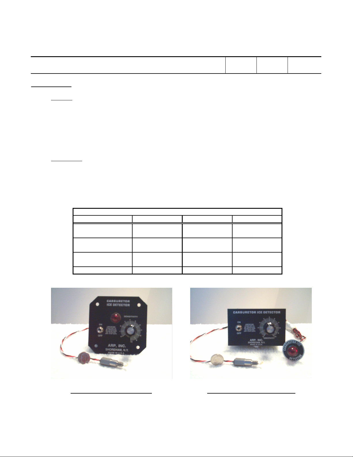
ARP's Carburetor Ice Detection Configurations
Configuration Type Part Number Aircraft Voltage Pictorial
"Panel Mount" 107AP-12 12V Photo 1
107AP-24 24V Photo 1
"Remote Mount" 107AP-R-12 12V Photo 2
107AP-R-24 24V Photo 2
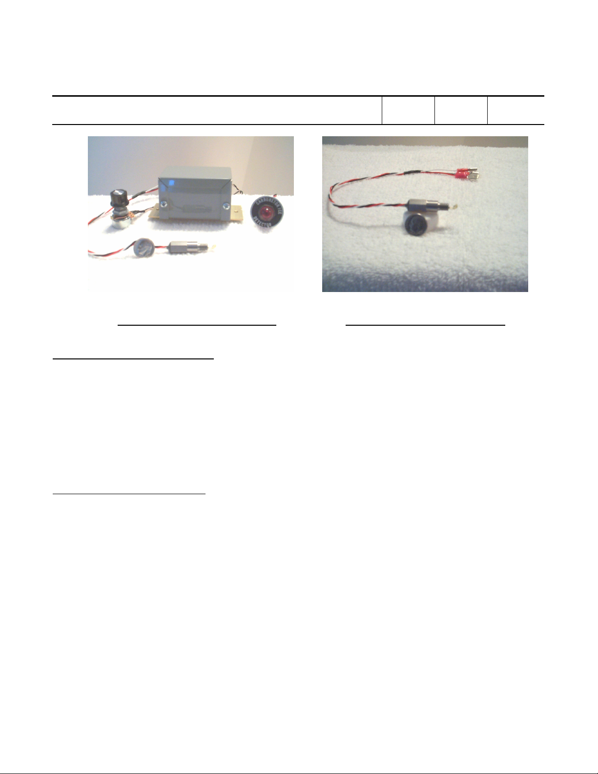
"Universal Mount" 107AP-U-12 12V Photo 3
107AP-U-24 24V Photo 3
"Probe Assembly" 107AP-P Both Photo 4
Revision B This sheet 1 Total Sheets
10
Photo 1 – “Panel Mount”
Photo 2 – “Remote Mount”
Page 2
ARP Inc. Document No. 107AP-INST
AIRCRAFT INSTALLATION MANUAL
Aircraft & Rotorcraft Products, Incorporated
Model Description: Carburetor Ice Detector
Model No.: 107AP
FAA STC No.: SA489EA
2.0 APPLICABLE DOCUMENTS
PL107AP-INST ARP Carburetor Ice Detector Installation Kit Parts List
107AP-SUPP FAA Flight Manual Supplement
STC SA489EA FAA Supplemental Type Certificate - Carburetor Ice Detector
FAR Part 43 FAA Federal Aviation Regulation - Maintenance, Preventive Maintenance,
AC 43.13-1A FAA Advisory Circular - Acceptable Methods, Techniques, and Practices –
AC 43.13-2A FAA Advisory Circular - Acceptable Methods, Techniques, and Practices –
3.0 CONFIGURATION TYPES
“Panel Mount” Carburetor ice detectors with the red warning light, sensitivity control and on/off
“Remote Mount” Carburetor ice detectors with the sensitivity control and on/off switch directly
“Universal Mount” Carburetor ice detectors with the red warning light, sensitivity control and on/off
Photo 3 – “Universal Mount”
Rebuilding, and Alterations
Aircraft Inspection and Repair
Aircraft Alterations
switch directly attached to the instrument panel.
attached to the instrument panel and the red warning light detached for remote
mounting. This warning light is electrically connected to the instrument with
discrete wires for installation in virtually any location.
switch detached from the unit’s instrument panel. These devices are electrically
connected to the instrument with discrete wires for installation in tight and remote
locations.
Photo 4 – “Probe Assembly”
Revision B This sheet 2 Total Sheets
10
Page 3

ARP Inc. Document No. 107AP-INST
AIRCRAFT INSTALLATION MANUAL
Aircraft & Rotorcraft Products, Incorporated
Model Description: Carburetor Ice Detector
Model No.: 107AP
FAA STC No.: SA489EA
4.0 MANUAL CONTENTS
Description Paragraph Numbers
• General Description 5.0
• Installation Instructions 6.0
• System Operations 7.0
5.0 GENERAL DESCRIPTION
5.1 ARP Carburetor Ice Detection Systems are designed to alert the pilot as to impending engine power loss
or stoppage due to ice / frost accumulation inside the carburetor so that carburetor heat can be applied.
Unlike temperature sensing devices, this carburetor ice detection system utilizes an electronic light
source and feedback sensor. A red warning light inside the cockpit is activated when the probe’s radiated
light beam and photo-detector sensor, located in the carburetor throat, is blocked due to ice / frost
formation. In the absence of carburetor ice / frost the red warning light automatically deactivates
5.2 These carburetor ice detection systems provide real-time detection of ice / frost formation within the
carburetor and alerts the pilot accordingly. It is completely independent of temperature or pressure
changes which do not affect the system operation except to melt away ice / frost accumulation.
5.3 The rotary sensitivity adjustment control knob is provided to adjust the system sensitivity level for ice /
frost detection. This setting should be just above the threshold where the red warning light deactivates
and should be set after engine start.
6.0 INSTALLATION INSTRUCTIONS
IMPORTANT— Read the following instructions completely prior to installation.
FAR Part 43 requires that methods, techniques, and practices acceptable to the FAA Administrator be
used by authorized personnel when altering civil aircraft. Methods, techniques, and practices other than
those prescribed in AC 43.13-1A and AC 43.13-2A may be used provided they are acceptable to the FAA
Administrator.
6.1 Gaining Access
Remove or open up the engine cowling to allow access to the engine, carburetor and firewall.
6.2 Carburetor Preparation
6.2.1 For carburetors equipped with a factory predrilled and tapped hole remove the existing plug in
the carburetor housing just below the throttle (or butterfly) valve and then proceed with
paragraph 6.4. (These carburetors have been equipped with a threaded brass plug in a ¼ X 28
tapped hole in lieu of a lead plug filling this access hole.)
6.2.2 If the carburetor is not equipped with a factory predrilled and tapped hole, proceed with
paragraph 6.3 for instructions on drilling and tapping a mounting hole in the carburetor barrel
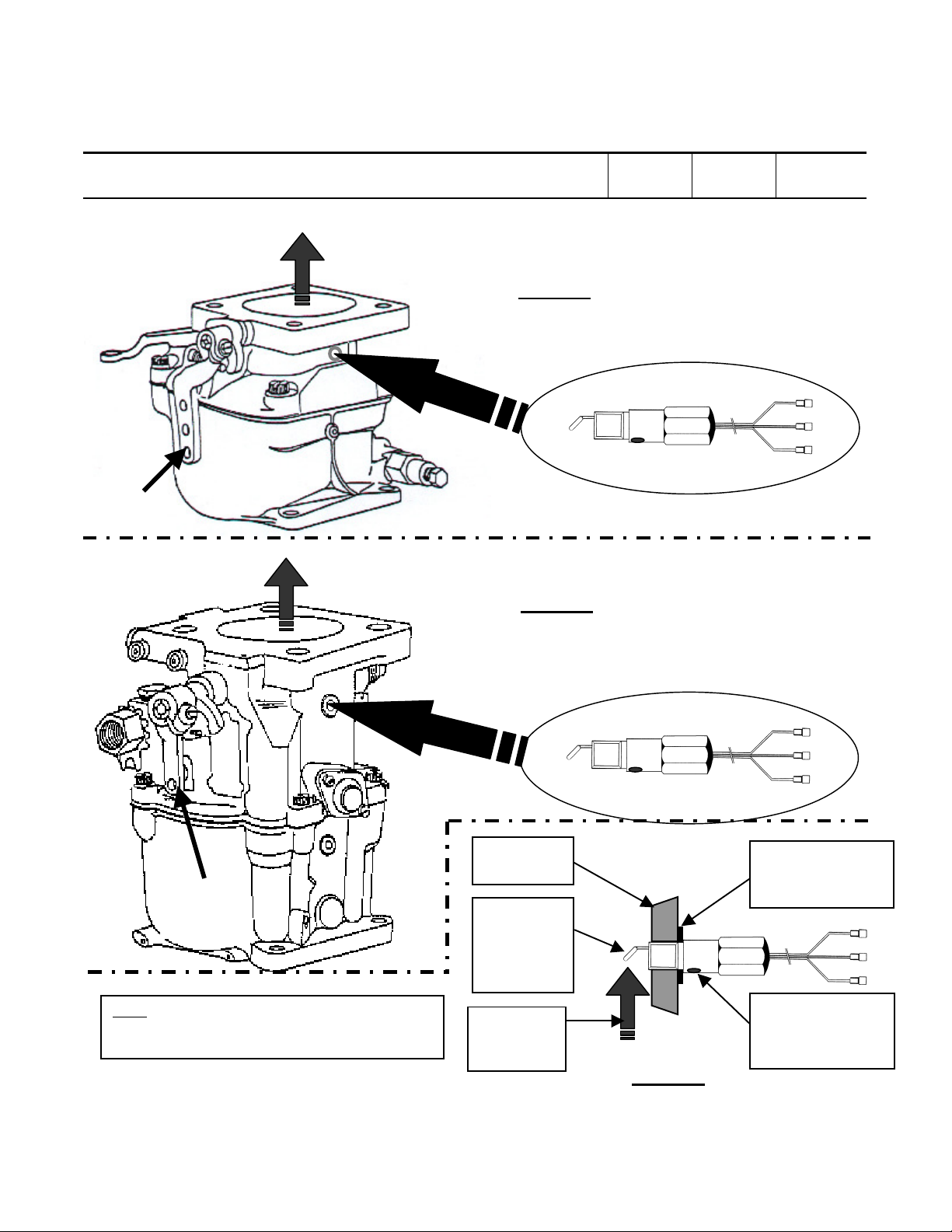
prior to proceeding with paragraph 6.4. (Refer to Figures 1 and 2.)
Revision B This sheet 3 Total Sheets
10
Page 4

ARP Inc. Document No. 107AP-INST
AIRCRAFT INSTALLATION MANUAL
Aircraft & Rotorcraft Products, Incorporated
Model Description: Carburetor Ice Detector
Model No.: 107AP
FAA STC No.: SA489EA
6.3 Drilling and Tapping Carburetor
Adjacent to the butterfly valve in all Precision Air-Motive (Facet or Marvel-Schebler) MA-2, MA-3, MA-4
and MA-4-5 series carburetors is a lead plug filling an access hole through which the idler jets were
drilled on the far side of the carburetor barrel. This lead plug fills a stepped hole just below the throttle
valve in the aluminum casting. The carburetor wall is approximately ¼” thick in which this plug is
inserted. The instructions prescribed below provides the process for removing the plug, drilling a larger
hole and tapping a female thread for mounting the ice detector probe securely at a point adjacent to the
butterfly valve. It is at this location the carburetor ice detection system will sense ice / frost
accumulation and warn the pilot of impending danger. (Refer to Figures 1, 2 and 3.)
6.3.1 Remove the carburetor assembly from the engine.
6.3.2 Secure the carburetor under a drill press and drill out the lead plug just below the throttle valve
using a 7/32” drill bit. Drill slowly and limit the drill travel so that the drill bit does not break
through and come in contact with the butterfly valve. (One technique is to apply a bit of putty
directly over the inner end of the lead plug to prevent the metal chips from entering the
carburetor. If the drill does not pass through the putty the process of removing the metal burrs
and chips is simplified.)
6.3.3 Remove all excess lead in order to create a smooth, flat perpendicular surface around the
outside of the hole. This will be the mating surface between the carburetor and the ice detector
probe.
6.3.4 Tap the hole with a lubricated ¼ X 28 tap.
6.3.5 Be careful to remove all metal burrs and chips from the interior of the carburetor.
6.3.6 Proceed with paragraph 6.4 for mounting the ice detector probe.
6.4 Mounting Ice Detector Probe
Open the throttle valve wide and carefully screw in the ice detector probe. Exercise caution not to bend
or move the probe-sensing component. Install a lock washer and the proper number of shim washers so
that when the probe is tightened the indicator marker (red or black dot, or vibra-etched scribed marking)
on the probe housing faces in the direction towards the carburetor air inlet. This will position the probesensing surface directly into the carburetor air stream. The probe assembly should be tightened by hand
as tight as possible and then only ¼ turn additional using a 3/8” short handle open-end wrench. This is
extremely important to prevent over tightening which can over stress the threads. (Refer to Figures 3.)
6.5 Electrical Wiring and System Check
At this time the electrical wiring may be installed to check the operation of the ice detector probe in the
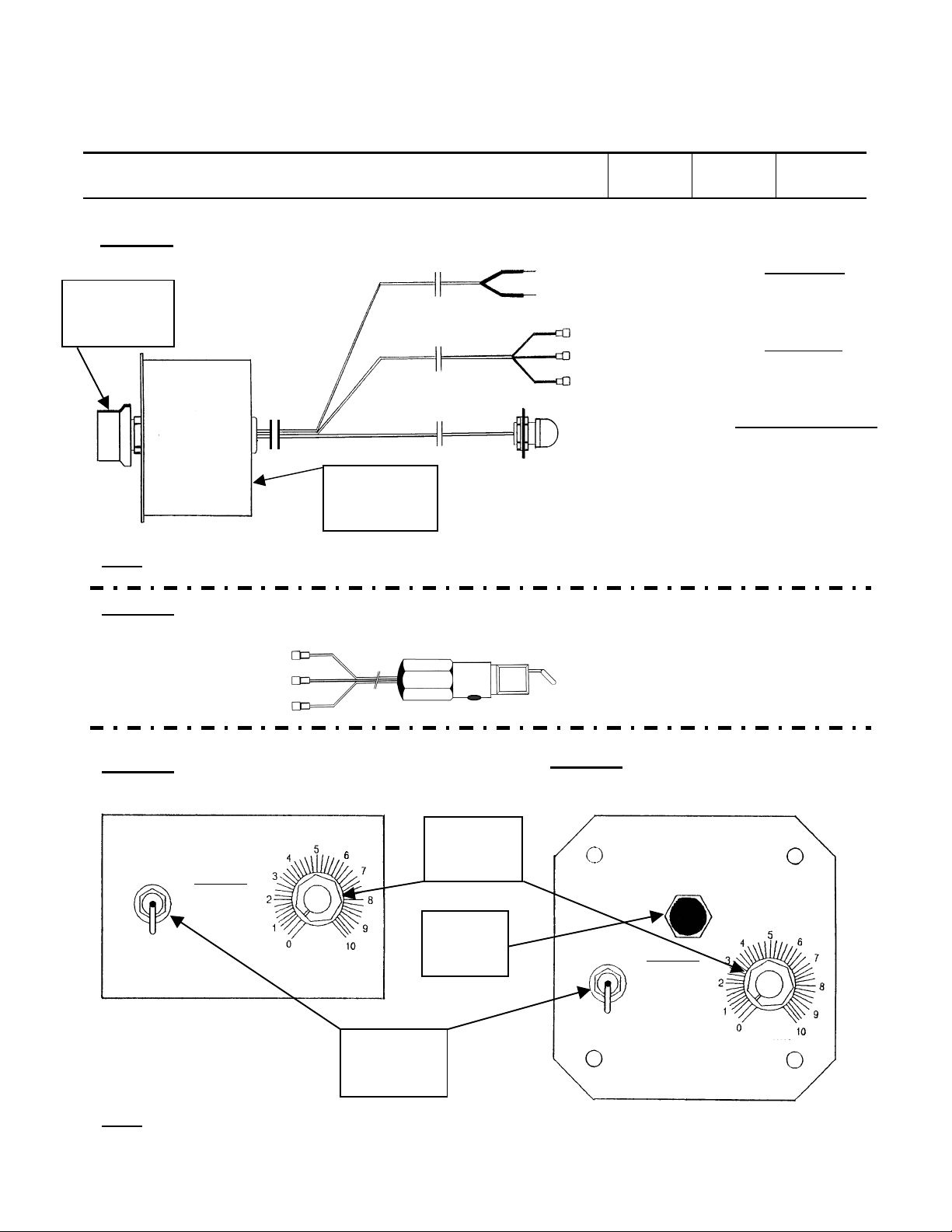
carburetor. (Refer to Figures 4 and 5.)
6.5.1 Make certain that a 12-Volt series carburetor ice detector is being installed on a 12-Volt aircraft
system, or a 24-Volt series on a 24-Volt system.
6.5.2 Power Cable Installation— Connect the instrument’s positive [+] power RED lead wire to the
positive [+] side of the aircraft electrical power and the negative [-] ground BLK lead wire to a
proper ground on the airframe. Make sure that the RED wire is the power wire from the
carburetor ice detector instrument case and not the probe assembly RED wire. Also, in most
Revision B This sheet 4 Total Sheets
10
Page 5

ARP Inc. Document No. 107AP-INST
AIRCRAFT INSTALLATION MANUAL
Aircraft & Rotorcraft Products, Incorporated
Model Description: Carburetor Ice Detector
Model No.: 107AP
FAA STC No.: SA489EA
aircraft the electrical system is positive [+] with the negative [-] battery post grounded to the
airframe. This means the instrument’s positive [+] power wire can be connected to the circuit
breaker or master switch. On aircraft with positive ground, the power wire must be reversed so
that plus meets plus.
6.5.3 System Operational Check— Connect the ice detector probe connectors to the instrument’s
probe cable connectors. Perform a system operational check described below (refer to Figures
6 and 7 for component setting locations). Make certain that the probe is in a dark area with little
or no light on it.
(a) Turn the instrument’s sensitivity adjustment knob to 0 or full counter-clockwise position.
(b) Set the instrument’s on/off power switch to the ON position.
(c) Slowly turn the sensitivity control up clockwise from 0 to approximately 5 to 8 (or higher).
(d) The red warning light should turn ON at 0 and turn OFF between 4 and 9.
(e) If this does not occur check the power supply, wires and connections.
(f) Be sure the proper color wires from the probe are connected to the same color wires on the
instrument.
6.5.4 Disconnect the probe connectors and re-install the carburetor assembly (if previously removed)
on the engine with the ice detector probe installed in the carburetor.
6.5.5 Probe Cable Installation— Route the three-wire probe cable from the instrument case through
the firewall to the carburetor where the ice detector probe is installed. Reconnect the probe
connectors. Replace the fireproof grommet and sealant (as required). Sealant approved for
firewalls is Proseal #700 (Coast Proseal Company, Chemical Division), or other approved
compound. If a hole does not already exist, drill a 9/16” hole through the firewall, remove all
burrs and sharp edges and install a grommet approved for firewalls (i.e. MS35449-2.9 or AN931-
2.9). A re-enforcing ring is not required provided the distance from other holes in the firewall is
not less than 1½”.
6.5.6 Clamp the probe cable with Adel clamps, tie-wraps, or equivalent every 12” to the carburetor, air
scoop and engine mount. Be sure to clamp the ice detector probe cable to the carburetor so that
there will be no cable movement at the probe due to engine vibration. Allow at least 6” to 8” of
slack between the clamping at the carburetor and the engine mount to allow for movement of the
engine on the mount.
6.5.7 Tape / insulate the connectors individually to prevent their touching and shorting out, and to seal
out dirt and oil.
6.6 Mounting Ice Detector Instrument and Components
Refer to AC 43.13-2A Chapter 11 for structural and design considerations when aircraft alterations
involve adding or relocating instruments. When making structural changes such as adding holes in the
aircraft’s instrument panel, refer to AC 43.13-2A Chapter 2, Paragraph 23.
6.6.1 As prescribed in AC 43.13-2A, all instruments shall be mounted in a location easily visible and
accessible to the pilot. The carburetor ice detector instrument’s red warning light and sensitivity
adjustment control should be positioned directly in front of the pilot within reach for adjustment.
6.6.2 Various mounting techniques may be deployed when installing the ice detector instrument.
When mounting the instrument case (for “Panel” or “Remote Mount” unit’s) in an opening on the
aircraft’s instrument panel make sure that the opening is suitable for the 2 3/4” x 2 1/8”
Revision B This sheet 5 Total Sheets
10
Page 6

ARP Inc. Document No. 107AP-INST
AIRCRAFT INSTALLATION MANUAL
Aircraft & Rotorcraft Products, Incorporated
Model Description: Carburetor Ice Detector
Model No.: 107AP
FAA STC No.: SA489EA
enclosure. Secure in-place with four #8-32 (for “Panel Mount” faceplate) or two #6-32 (for
“Universal Mount” mounting plate) aluminum round head screws, nuts and lock washers. Selflocking nuts may be used in lieu of standard nuts and lock washers. The rear of the instrument
case (for “Panel” or Remote Mount” units) may also be removed and mounted directly to the
aircraft’s instrument panel, or small 24ST aluminum brackets may be installed on the sides of the
instrument’s rear section in order to mount it in a rectangular cutout in the aircraft’s instrument
panel.
6.6.3 When installing the red warning light, remove the hex nut (closest to the red lens cover), lock
washer and remote lamp faceplate. Insert the threaded lamp holder through the back end of a
1/2” drilled hole in the aircraft’s instrument panel. Peel off the paper strip covering the dry
adhesive on the remote lamp faceplate and properly position the faceplate on the aircraft’s
instrument panel. Screw nut with lock washer back on and tighten. (Adjusting both nuts may be
required to compensate for the thickness of the aircraft’s instrument panel.) Similar technique
applies when mounting the sensitivity control and the on/off switch, except the mounting hole for
the sensitivity control is 3/8” and 1/4” for the on/off switch.
6.6.4 For “Universal Mount” Carburetor-Ice Detectors, P/N’s 107AP-U-12 and 107AP-U-24, affix the
Limitation placard, P/N 107AP-106 (provided with the installation kit and illustrated below)
adjacent to the red warning light and in clear view of the pilot.
6.6.5 Your ARP Carburetor Ice Detector is ready for operation.
7.0 SYSTEM OPERATIONS
Prior to operating an aircraft with ARP carburetor ice detection system, the ice / frost detection sensitivity
threshold level needs to be adjusted just above where the red warning light deactivates. Refer to the
FAA Flight Manual Supplement.
7.1 Sensitivity Setting
After turning the aircraft master switch to the ON position and starting the aircraft engine, set the
carburetor ice detector power switch to ON, and rotate the sensitivity adjustment control knob to zero or
full counter-clockwise position. The red warning light will turn ON. Slowly rotate the sensitivity control
knob up or clockwise until the red warning light turns OFF. This is the threshold setting for ice / frost
detection.
Note: After engine start, increase power to run-up setting, and apply carburetor heat for at least 30
seconds prior to adjusting the sensitivity adjustment control knob, to ensure that no ice / frost is present
when adjustment is made. Every time a readjustment of the sensitivity adjustment control is required,
carburetor heat must be applied for at least 30 seconds, prior to such adjustment, to ensure that no ice /
frost is present in the carburetor.
7.2 In-Flight Operation
7.2.1 After the sensitivity threshold setting has been established, be sure the carburetor ice detector
switch is ON and remains ON at all times during flight.
LIMITATION: FLIGHT NOT TO
BE PREDICATED ON USE OF
CARBURETOR ICE DETECTOR
Revision B This sheet 6 Total Sheets
10
Page 7

ARP Inc. Document No. 107AP-INST
AIRCRAFT INSTALLATION MANUAL
Aircraft & Rotorcraft Products, Incorporated
Model Description: Carburetor Ice Detector
Model No.: 107AP
FAA STC No.: SA489EA
7.2.2 If the red warning light turns ON, indicating initial ice / frost formation on the probe within the
carburetor throat, immediately apply carburetor heat (to both engines if a twin engine aircraft)
until the red warning light turns OFF automatically. This indicates the ice / frost has been
cleared within the carburetor.
7.2.3 If the red warning light does not turn OFF after approximately two minutes of heat application,
the cause may either be an improper sensitivity setting or carburetor icing conditions. Continue
flight operation using Flight Manual Procedures and check the carburetor ice detector sensitivity
setting after landing.
Note: If the sensitivity setting is improperly set too low, increasing or rotating clockwise the
sensitivity adjustment control knob slightly more above the threshold level can correct it.
7.3 System Test
To test the carburetor ice detector system, turn the instrument’s power switch OFF then ON during
normal operation. The red warning light will go ON then OFF indicating that all components are
operating properly. (Cycling the power switch OFF and ON simulates ice / frost on the probe.)
7.4 Normal Maintenance
7.4.1 With increasing time of operation on the engine (or twin engines) a slight film of fuel residue may
form on the probe, which may result in a slight reduction of sensitivity as compared to the
original setting when the ice detector is first installed. This will be observed when it is required to
turn the sensitivity adjustment knob to an ever increasing clockwise or higher setting as time
goes on. However, the basic ice detection sensitivity is not reduced when adjusted as prescribed
in paragraph 7.1.
7.4.2 In the event the sensitivity adjustment control must be turned to the full clockwise position and
the red warning light does not deactivate, then the probe must be removed and cleaned with a
soft cloth (preferably a cotton swab) and white gasoline. Exercise caution not to bend or move
the probe’s photo-detecting sensing component. Once cleaned, reinstall the probe assembly and
check out the system using the instructions prescribed in this manual.
-END-
Proprietary rights of Aircraft & Rotorcraft Products, Inc. are included in the information disclosed herein. This
document shall not be reproduced or transferred to other documents or used or disclosed to others for
manufacturing or for any purpose except as specifically authorized in writing by Aircraft & Rotorcraft Products,
Inc.
Prepared / Approved: H.P. Rask Document No. 107AP-INST, Revision: B
Date: 31-January-02
File Name: 107ap-inst_rev_b.doc
Revision B This sheet 7 Total Sheets
10
Page 8
ARP Inc. Document No. 107AP-INST
Probe Mounted in Carburetor Wall
etched marking on probe
Component
(Probe)
(Probe)
(Probe)
(from Ground)
(See Note)
Direction of
AIRCRAFT INSTALLATION MANUAL
Aircraft & Rotorcraft Products, Incorporated
Model Description: Carburetor Ice Detector
Model No.: 107AP
FAA STC No.: SA489EA
Direction of Carburetor Air Stream
Throttle
(Into Engine)
Handle
Revision B This sheet 8 Total Sheets
10
Figure 1
Model MA-2, MA-3 and MA-4
Direction of Carburetor Air Stream
(Into Engine)
Throttle
Handle
Figure 2
Model MA-4-5
Carburetor
Wall
Probe
Sensing
(Faces Air
Stream)
Figure 5
Detail Side View
(to Engine)
Shim Washers &
Lock Washer
(See Note)
Note: Install proper number of shims to ensure
black or red dot, or vibrahousing faces towards the carburetor air inlet.
Carburetor
Air Stream
Black or Red Dot,
or Vibra-Etched
Marking
Figure 3
Detailed Side View
Probe Mounted in Carburetor Wall
Page 9
Adjustment
FLIGHT NOT TO BE
ON USE OF CARB
FLIGHT NOT TO BE
ON USE OF CARB
Configuration
ARP Inc. Document No. 107AP-INST
AIRCRAFT INSTALLATION MANUAL
Aircraft & Rotorcraft Products, Incorporated
Model Description: Carburetor Ice Detector
Model No.: 107AP
FAA STC No.: SA489EA
Figure 4
Ice Detector Instrument
Sensitivity
Adjustment
Knob
(Instrument)
RED [+]
BLK [-]
Revision B This sheet 9 Total Sheets
RED [Light Sensor]
BLK [Ground]
WHT [Light Source]
Remote Warning Light
10
Power Cable
(Standard)
Probe Cable
(Standard)
(See Note 1)
“Remote”
Shown Here
Notes: (1) Remote warning light shown is part of “Remote” configuration unit.
Figure 5 (Standard Equipment)
Ice Detector Probe
(Probe)
RED [Light Sensor]
BLK [Ground]
WHT [Light Source]
Figure 6 (Front View)
“Remote Mount” Configuration
CARBURETOR ICE DETECTOR
ON
LIMITATION:
PREDICATED
ICE DETECTOR.
(SEE 107AP-SUPP)
OFF
ARP, INC.
SHOREHAM, N.Y.
MADE IN U.S.A.
SENSITIVITY
Sensitivity
Knob
Red
Warning
Light
On/Off
Power
Switch
Figure 7 (Front View)
“Panel Mount” Configuration
CARBURETOR
ICE DETECTOR
ON
LIMITATION:
PREDICATED
ICE DETECTOR.
(SEE 107AP-SUPP)
OFF
ARP, INC.
SHOREHAM, N.Y.
MADE IN U.S.A.
SENSITIVITY
Notes: (2) For “Universal Mount” configuration, the components are the same except they are detached from the unit’s
instrument panel.
Page 10

ARP Inc. Document No. 107AP-INST
AIRCRAFT INSTALLATION MANUAL
Aircraft & Rotorcraft Products, Incorporated
Model Description: Carburetor Ice Detector
Model No.: 107AP
FAA STC No.: SA489EA
This document is intended to be used by the aircraft or rotorcraft owner / operator, or an authorized representative, for the
installation and / or operation of an ARP product. If the user of this document finds an error or feels that improvements can
be made, ARP would appreciate your input. Please fill out this form and forward it via:
• Mail— ARP Inc., 2 Middle Cross Road, Shoreham, N.Y. 11786-1440
• FAX— (631) 821-7933 or Phone— (631) 744-1893
• E-Mail— [email protected]
Document No. Rev. Section/Page
IMPROVEMENT TYPE—
Documentation error (format, punctuation, spelling)
Content error
Enhancement or refinement
DESCRIPTION OF IMPROVEMENT—
PROPOSED CHANGE (attach marked-up text or proposed rewrite)—
Please feel free to provide any general comments that might improve future revisions of this document. Thank you.
WARRANTY INFORMATION
Name: _____________________________________________________ Phone No.: _______________________
Address: ___________________________________________________ FAX No.: ________________________
___________________________________________________ E-Mail No.: ______________________
Aircraft, Make: _____________________ Model: _________________ Year: ___________________________
Registration No.: ______________________________ Serial No.: _______________________________________
Remarks / Sugestions:____________________________________________________________________________
____________________________________________________________________________
OWNER/OPERATOR— Please complete warranty information and return to ARP, Inc. Thank You.
Revision B This sheet
10
Total Sheets
10
 Loading...