

Aros Spring T 500, Spring T 1500, Spring T 2000, Spring R 500, Spring R 800 User Manual
...
UNINTERRUPTIBLE POWER SUPPLY
LINE-INTERACTIVE
500-3000VA
(BATTERY BOX)
- Manuale d’uso -
- User’s manual -
- Bedienungsanleitung -


Questa parte del manuale contiene precauzioni da seguire scrupolosamente in quanto
riguardano la SICUREZZA.
Installazione
¾ Connettere l’UPS solo a prese con protezione di terra collegata.
¾ La presa protetta utilizzata per il collegamento deve essere facilmente accessibile e vicino all’UPS.
¾ Per il collegamento dell’UPS alla rete elettrica utilizzare solamente cavi di alimentazione testati VDE e
marchiati CE.
¾ Per le connessioni dei carichi all’UPS utilizzare solamente cavi di alimentazione testati VDE e marchiati
CE.
¾ In fase di installazione dell’apparecchiatura accertarsi che la somma delle correnti di dispersione verso
terra dell’UPS e degli altri dispositivi collegati sulla stessa linea non superi i 3.5 mA.
Utilizzo
¾ Questo UPS può essere utilizzato da qualsiasi individuo (purché accorto e prudente).
¾ Non scollegare il cavo di alimentazione dell’UPS o la spina di ingresso durante il funzionamento in
quanto verrebbe meno la protezione di terra dell’UPS e dei carichi collegati.
¾ L’UPS dispone di una fonte di energia interna (batterie). Le prese di uscita dell’UPS potrebbero, quindi,
essere in tensione anche se l’UPS risulta scollegato dalla rete elettrica di alimentazione.
¾ Per scollegare completamente l’UPS, prima spegnere l’apparecchiatura premendo il tasto OFF,
dopodiché scollegare il cavo di alimentazione.
Ambiente operativo, manutenzione e guasti
¾ L’UPS funziona a tensione pericolose. Ogni riparazione deve essere effettuata solamente da personale
qualificato.
¾ Attenzione - Rischio di scossa elettrica. Persino dopo aver scollegato l’apparecchiatura dalla rete
elettrica di alimentazione, i componenti interni dell’UPS essendo collegati alle batterie, sono ancora in
tensione, quindi pericolosi. Prima di effettuare qualsiasi tipo di riparazione o manutenzione, scollegare le
batterie e verificare che non sia presente tensione.
¾ Solo persone con preparazione adeguata a riguardo delle necessarie misure di precauzione e delle
batterie possono effettuare la sostituzione delle stesse o effettuare operazioni di supervisione. Le
persone non autorizzate devono rimanere lontane dalle batterie
¾ Attenzione - Le batterie possono essere causa di scossa elettrica e sono dotate di un alta corrente di
cortocircuito. Prendere le necessarie precauzioni e misure di sicurezza di seguito quando si maneggiano
delle batterie:
- non indossare orologi, aneli, catenine o qualsiasi altro materiale metallico
- usare solo attrezzi con impugnatura isolata
¾ Quando si esegue un cambio batterie fare attenzione ad installare lo stesso numero di batterie e dello
stesso tipo.
¾ Non gettare le batterie nel fuoco: possono esplodere.
¾ Non tentare di aprire o danneggiare le batterie: l’elettrolita contenuto in esse è nocivo per la pelle e per
gli occhi e potrebbe essere tossico.
¾ Non disassemblare l’UPS.
3

GB
SAFETY
GB
This part of the manual contains precautions that must absolutely be followed as they relate to
SAFETY.
Installation
¾ Connect the UPS system only to an earthed shockproof socket outlet.
¾ The building wiring socket outlet (shockproof socket outlet) must be easily accessible and close to the
UPS system.
¾ Please use only VDE-tested, CE-marked mains cable (e.g. the mains cable of your computer) to connect
the UPS system to the building wiring socket outlet (shockproof socket outlet).
¾ Please use only VDE-tested, CE-marked power cables to connect the loads to the UPS system.
¾ When installing the equipment, it should ensure that the sum of the leakage current of the UPS and the
connected consumer does not exceed 3.5mA.
Operation
¾ This UPS is operated by laymen.
¾ Do not disconnect the mains cable on the UPS system or the building wiring socket outlet (shockproof
socket outlet) during operations since this would cancel the protective earthing of the UPS system and of
all connected loads.
¾ The UPS system features its own, internal current source (batteries). The UPS output sockets may be
electrically live even if the UPS system is not connected to the building wiring socket outlet.
¾ In order to fully disconnect the UPS system, first press the OFF-switch then disconnect the mains.
Maintenance, servicing and faults
¾ The UPS system operates with hazardous voltages. Repairs may be carried out only by qualified
maintenance personnel.
¾ Caution - risk of electric shock. Even after the unit is disconnected from the mains power supply
(building wiring socket outlet), components inside the UPS system are still connected to the battery and
are still electrically live and dangerous. Before carrying out any kind of servicing and/or maintenance,
disconnect the batteries and verify that no current is present.
¾ Only persons adequately familiar with batteries and with the required precautionary measures may
exchange batteries and supervise operations. Unauthorised persons must be kept well away from the
batteries.
¾ Caution -Batteries may cause electric shock and have a high short-circuit current. Please take the
precautionary measures specified below and any other measures necessary when working with
batteries:
- remove wristwatches, rings and other metal objects
- use only tools with insulated grips and handles.
¾ When changing batteries, install the same number and same type of batteries.
¾ Do not dispose of batteries in a fire. The batteries may explode.
¾ Do not open or mutilate batteries. Released electrolyte is harmful to the skin and eyes. It may be toxic.
¾ Do not dismantle the UPS system.
4

Dieser Teil des Handbuchs enthält sorgfältig zu befolgende Vorsichtsmassnahmen, da sie sich
auf die SICHERHEIT beziehen.
Installation
¾ Die USV nur an eine geerdete, stromschlagsichere Steckdose anschließen.
¾ Der Netzanschluss (stromschlagsichere Steckdose) muss leicht zugänglich und in der Nähe des USV
Systems sein.
¾ Nur VDE getestete Netzkabel mit CE Siegel (z.B. die Netzkabel Ihres Computers) zum Anschluss der
USV an den Netzanschluss (stromschlagsichere Steckdose) benutzen.
¾ Die Verbraucher nur mit VDE getesteten Netzkabel mit CE Siegel an die USV anschließen.
¾ Bei Installieren der Geräte sicherstellen, dass die Leckströme der UPS und der angeschlossen
Verbraucher zusammen unter 3,5 mA bleiben.
Betrieb
¾ Die UPS kann von Nichtfachleuten betrieben werden.
¾ Während des Betriebs die Netzkabel der USV nicht vom Netzanschluss (stromschlagsichere Steckdose)
trennen, da damit eine Erdung der UPS und aller angeschlossenen Verbraucher nicht mehr gegeben ist.
¾ Die USV hat ihre eigene interne Stromquelle (Batterien). Daher können die Ausgangssteckdosen der
USV auch unter Spannung stehen, wenn die USV vom Gebäudenetz getrennt ist.
¾ Um das USV System ganz abzuschalten, erst den OFF Schalter drücken und dann die Netzkabel vom
Netz trennen.
Wartung, Service und Störungen
¾ Die USV arbeitet mit gefährlichen Spannungen. Reparaturen dürfen nur von qualifizierten Technikern
vorgenommen werden.
¾ Achtung - Gefahr von elektrischen Schlägen. Auch nach Trennen der USV vom Gebäudenetz
(Steckdose) bleiben Komponenten im System mit den Batterien verbunden und stehen daher unter
gefährlicher Spannung. Vor irgendwelchen Wartungs- und/oder Servicearbeiten, die Batterien abtrennen
und prüfen, dass kein Strom fließt.
¾ Nur wer mit Batterien und den für sie erforderlichen Sicherheitsmaßnahmen hinreichend vertraut ist, darf
Batterien tauschen und die Arbeiten überwachen. Nicht berechtigte Personen müssen von den Batterien
fern gehalten werden.
¾ Achtung -Batterien können elektrische Schläge verursachen und haben einen starken
Kurzschlussstrom. Beim Arbeiten an den Batterien die folgenden und alle anderen bei Arbeiten mit
Batterien notwendigen Vorsichtsmaßnahmen ergreifen:
- Armbanduhren, Ringe und sonstige Metallgegenstände ablegen
- Nur Werkzeug mit isolierten Handgriffen benutzen.
¾ Bei Batteriewechsel immer die gleiche Anzahl und den gleichen Typ von Batterien installieren.
¾ Batterien nicht in Feuer werfen: sie können explodieren.
¾ Batterien nicht öffnen oder beschädigen. Ausfließendes Elektrolyt ist gefährlich für Haut und Augen und
kann giftig sein.
¾ Das USV System nicht auseinandernehmen.
5

Cette partie du Manuel concerne les mesures de SÉCURITÉ à suivre scrupuleusement.
Installation
¾ Raccorder l’ASI exclusivement à des prises à ayant une protection de terre branchée.
¾ La prise protégée utilisée pour le branchement doit être facilement accessible et située à proximité de
l’ASI.
¾ Pour le branchement de l’ASI au réseau électrique, utiliser exclusivement des câbles d’alimentation
testés VDE et marqués CE.
¾ Pour les connexions de charges à l’ASI, utiliser exclusivement des câbles d’alimentation testés VDE et
marqués CE.
¾ Pendant la phase d’installation de l’appareil, s’assurer que la somme des courants de dispersion vers la
terre de l’ASI et des autres dispositifs branchés sur la même ligne ne dépasse pas les 3.5 mA.
Utilisation
¾ Cet ASI peut être utilisé par tout adulte (à condition qu’il soit avisé et prudent).
¾ Ne débrancher ni le câble d’alimentation de l’ASI ni la fiche d’entrée pendant le fonctionnement de ce
dernier car ceci éliminerait la protection de terre de l’ASI et des charges qui y sont branchées.
¾ L’ASI dispose d’une source d’énergie interne (batteries). Les prises de sortie de l’ASI pourraient donc
être sous tension même si l’ASI est débranché du réseau électrique d’alimentation.
¾ Pour débrancher complètement l’ASI, éteindre d’abord l’appareil en pressant la touche OFF, puis
débrancher le câble d’alimentation.
Environnement de travail, entretien et pannes
¾ L’ASI fonctionne sous des tensions dangereuses. Toute réparation doit être effectuée exclusivement par
un personnel qualifié.
¾ Attention – Risque de décharge électrique. Même après avoir débranché l’appareil du réseau électrique
d’alimentation, les composants présents à l’intérieur de l’ASI étant encore raccordés aux batteries sont
encore sous tension et donc dangereux. Avant d’effectuer tout type de réparation ou d’entretien,
débrancher les batteries et vérifier l’absence de tension.
¾ Seules les personnes ayant une préparation adéquate relative aux consignes de sécurité et aux
batteries peuvent effectuer le remplacement de ces dernières ou exécuter des opérations de
supervision. Toute personne non autorisée doit se tenir loin des batteries.
¾ Attention – Les batteries peuvent causer une décharge électrique et sont pourvues d’un courant élevé
de court-circuit. Prendre les précautions et les consignes de sécurité nécessaires reportées ci-après en
cas de manipulation des batteries:
- ne porter ni montres, ni bagues, ni chaînes ni tout autre objet métallique
- utiliser exclusivement des outils ayant une poignée isolée
¾ En cas de remplacement des batteries, installer le même nombre et le même type de batteries.
¾ Ne pas jeter les batteries dans le feu : elles pourraient exploser.
¾ Ne pas essayer d’ouvrir ni d’endommager les batteries: l’électrolyte qu’elles contiennent est nocif pour la
peau et les yeux et il pourrait s’avérer toxique.
¾ Ne pas démonter l’ASI.
6

Esta parte del manual contiene las precauciones a seguir cuidadosamente en lo que se refiere
a la SEGURIDAD.
Instalación
¾ Conectar el SAI únicamente a enchufes con protección de toma de tierra.
¾ El enchufe protegido utilizado para la conexión debe ser de fácil acceso y encontrarse cerca del SAI.
¾ Para la conexión del SAI a la red eléctrica utilizar únicamente cables de alimentación ensayados VED y
con marca CE.
¾ Para la conexión de las cargas al SAI utilizar únicamente cables de alimentación ensayados VED y
marca CE.
¾ En la fase de instalación del aparato asegurarse que la suma de las corrientes de dispersión hacia tierra
del SAI y de los demás dispositivos conectados a la misma línea no supere los 3,5 mA.
Uso
¾ Este SAI puede ser utilizado por cualquier persona (siempre que sea razonable y prudente).
¾ No desconectar el cable de alimentación del SAI o la clavija de entrada durante el funcionamiento ya
que se anularía la protección de tierra del SAI y de las cargas conectadas.
¾ El SAI dispone de una fuente de energía interna (baterías). El enchufe de salida del SAI podría, por ello,
tener tensión incluso aunque el SAI esté desconectado de la red eléctrica de alimentación del SAI.
¾ Para desconectar completamente el SAI, apagar primero el aparato pulsando el botón OFF, y luego
desconectar el cable de alimentación.
Entorno de funcionamiento, mantenimiento y averías
¾ El SAI funciona con tensiones peligrosas. Cualquier reparación debe ser realizada únicamente por
personal cualificado.
¾ Atención - Riesgo de descarga eléctrica. Incluso después de desconectar el aparato de la red eléctrica
de alimentación, los componentes internos del SAI continúan estando conectados a las baterías y por lo
tanto poseen una tensión peligrosa. Antes de efectuar cualquier reparación o mantenimiento,
desconectar las baterías y comprobar que no existe tensión.
¾ Únicamente las personas con la formación adecuada en relación con las necesarias medidas de
precaución y de las baterías pueden realizar la sustitución de las mismas o efectuar operaciones de
supervisión. Las personas no autorizadas deberán mantenerse alejadas de las baterías.
¾ Atención - Las baterías pueden provocar descargas eléctricas y poseen una alta corriente de
cortocircuito. Tomar las necesarias precauciones y las medidas de seguridad que se indican a
continuación cuando se manejen las baterías:
- quitarse los relojes, anillos, cadenas y cualquier otro material metálico
- emplear sólo herramientas con una empuñadura metálica
¾ Cuando se realice un cambio de baterías es necesario instalar el mismo número de baterías y del
mismo tipo.
¾ No tirar las baterías al fuego: podrían explotar.
¾ No intentar abrir o dañar las baterías: el electrolito contenido en las mismas es dañino para la piel y
para los ojos, y podría ser tóxico.
¾ No desmontar las baterías.
7

Den här delen av handboken innehåller försiktighetsåtgärder som ska följas noggrant eftersom
de har att göra med SÄKERHETEN.
Installation
¾ Anslut UPS-enheten (oavbrytbar strömförsörjning) endast till ett jordat standardvägguttag.
¾ Vägguttaget (standardvägguttag) måste vara lättillgängligt och nära UPS-enheten.
¾ Använd endast VDE-testade, CE-godkända sladdar (t e datorns sladd) för att ansluta UPS-enheten till
vägguttaget (standardvägguttag).
¾ Använd endast VDE-testade, CE-godkända sladdar för att ansluta förbrukaren till UPS-enheten.
¾ Vid installation av enheten skall den säkra att läckströmmen från UPS-enheten och den anslutna
förbrukaren inte överstiger 3.5mA.
Handhavande
¾ Denna UPS handhas av lekmän.
¾ Lossa inte sladden från UPS-enheten eller vägguttaget (standardvägguttag) under användning då detta
avbryter det jordade skyddet hos UPS-enheten samt alla anslutna förbrukare.
¾ UPS-enheten utmärks av en egen intern strömkälla (batterier). UPS-enhetens uttag kan vara
strömförande trots att UPS-enheten inte är ansluten till vägguttaget.
¾ Tryck först på strömbrytaren AV och lossa därefter sladden för att helt och hållet koppla ur UPS-
enheten.
Underhåll, service och fel
¾ UPS-enheten fungerar under farlig spänning. Reparationer får endast utföras av behörig
underhållspersonal.
¾ Varning – risk för strömstöt. Även efter att enheten kopplats loss från strömkällan (vägguttaget) är
komponenter inuti UPS-enheten fortfarande anslutna till batteriet och därmed fortfarande strömförande
och farliga. Före något slag av service och/eller underhåll måste batterierna kopplas ur och kontrolleras
att ingen ström finnes.
¾ Endast personer som är förtrogna med batterier och nödvändiga försiktighetsåtgärder får byta batterier
och övervaka funktionen. Obehöriga får ej komma i kontakt med batterierna.
¾ Varning – batterierna kan orsaka strömstöt och har hög kortslutningsström. Var vänlig iaktta nödvändiga
försiktighetsåtgärder enligt nedan samt alla övriga nödvändiga åtgärder vid arbete med batterierna:
- ta av klockarmband, ringar och övriga metallföremål
- använd endast verktyg med isolerade grepp och handtag.
¾ Vid byte av batterier skall de ersättas med samma antal och typ av batterier.
¾ Kasta aldrig batterier i öppen eld. Batterierna kan explodera.
¾ Försök inte öppna eller förstöra batterierna. Frigjord batterivätska är farlig för hud och ögon. Den kan
vara giftig.
¾ Försök inte ta isär UPS-enheten
9

Dit gedeelte van de handleiding bevat de VEILIGHEIDSVOORSCHRIFTEN die strikt opgevolgd
dienen te worden.
Installatie
¾ Steek de stekker van het UPS systeem in een geaard schokbestendig stopcontact.
¾ Het stopcontact van de hoofdleiding (schokbestendig stopcontact) moet gemakkelijk toegankelijk zijn en
zich in de buurt van het UPS systeem bevinden.
¾ Gebruik uitsluitend VDE-geteste, CE-gemarkeerde kabels (bijv. de kabel van uw computer) om de UPS
te verbinden met het stopcontact (schokbestendig stopcontact).
¾ Gebruik uitsluitend VDE-geteste, CE-gemarkeerde stroomkabels om de elektronische apparaten met het
UPS systeem te verbinden.
¾ Bij de installatie van de toestellen dient men erop te letten dat de som van de lekstroom van de UPS en
de verbonden verbruiker niet hoger is dan 3.5mA.
Bediening
¾ Deze UPS wordt bediend door niet deskundigen.
¾ Koppel de hoofdleiding niet los van het UPS systeem of het stopcontact (schokbestendig stopcontact)
wanneer het in gebruik is. Dit kan de beschermende aarding van het UPS systeem en alle verbonden
elektronische apparaten teniet doen.
¾ Het UPS systeem heeft een eigen stroombron (batterijen). De uitgangscontacten van de UPS kunnen
elektrisch geladen zijn zelfs als het UPS systeem niet verbonden is met het stopcontact van de kabels
voor vaste aanleg.
¾ Om het UPS systeem volledig los te koppelen dient u eerst op de "OFF" schakelaar te drukken en
daarna de hoofdleiding uit te trekken.
Onderhoud, controle en foutmeldingen
¾ Het UPS systeem werkt met gevaarlijke voltages. Reparaties kunnen uitsluitend uitgevoerd worden door
deskundig onderhoudspersoneel.
¾ Opgelet – risico voor elektrische schokken. Zelfs nadat de eenheid is losgekoppeld van de stroombron
(stopcontact) zijn er binnenin het UPS systeem nog steeds onderdelen verbonden met de batterij en
deze zijn nog steeds elektrisch geladen en gevaarlijk. U dient alle batterijen los te koppelen en zeker te
zijn dat er geen stroom aanwezig is voor iedere vorm van controle en/of onderhoud.
¾ Uitsluitend personen met voldoende kennis van batterijen en met de vereiste voorzorgsmaatregelen
mogen batterijen verwisselen en toezicht houden op de bediening. Onbevoegde personen moeten uit de
buurt van de batterijen blijven.
¾ Opgelet – Batterijen kunnen elektrische schokken veroorzaken en ze hebben een hoge kortsluitstroom.
Neem de nodige voorzorgsmaatregelen zoals hieronder aangegeven en iedere andere maatregel nodig
tijdens het werken met batterijen:
- verwijder uurwerken, ringen en andere metalen voorwerpen
- gebruik enkel werktuigen met geïsoleerde handvaten.
¾ Wanneer u batterijen verwisselt, installeert u altijd hetzelfde aantal en type batterijen.
¾ Gooi de batterijen nooit in het vuur. De batterijen kunnen ontploffen.
¾ Probeer de batterijen niet te openen of te verwringen. De vrijgekomen elektrolyt kan schadelijk zijn voor
de huid en de ogen. Het kan ook giftig zijn.
¾ U mag het UPS systeem niet demonteren.
10

Esta parte do manual contém precauções que devem ser seguidas rigorosamente, pois
respeitam à SEGURANÇA.
Instalação
¾ Somente conecte o sistema de alimentação ininterrupta (UPS) a uma tomada eléctrica anti choque com
ligação terra.
¾ A caixa da cablagem de edifício com a saída da tomada eléctrica anti choque deve estar em lugar de
fácil acesso e bem próxima ao UPS.
¾ Favor somente utilizar cabo portador principal VDE-testado e de marcação CE (ex. cabos principais do
seu computador) para conectar o sistema UPS à saída da caixa da cablagem de edifício (tomada
eléctrica anti choque).
¾ Favor somente utilizar cabos distribuidores de corrente VDE-testados e de marcação CE para conectar
cargas ao UPS.
¾ Ao instalar o equipamento, certificar-se de que a soma da perda de corrente eléctrica do UPS e do
consumidor de energia conectado não exceda 3.5mA.
Funcionamento
¾ Este UPS pode ser operado por pessoas não especializadas.
¾ Não desconecte o cabo de alimentação principal do UPS ou da saída da caixa da cablagem de edifício
(tomada anti choque) durante o funcionamento, pois este acto cancelaria a protecção da ligação terra
do UPS e de todas as cargas conectadas.
¾ O UPS possui sua própria fonte de corrente de energia interna (baterias). As tomadas de saída do UPS
estão sob tensão eléctrica, mesmo quando o UPS não está conectado à caixa de cablagem do edifício.
¾ Para desconectar totalmente o sistema UPS, aperte primeiramente o interruptor OFF, para então
desconectar os principais cabos condutores.
Manutenção, assistência técnica e falhas
¾ O UPS funciona com tensões de alto risco. Consertos somente deverão ser feitos por técnicos de
manutenção qualificados.
¾ Atenção – risco de choque eléctrico. Mesmo após desconectar o equipamento da principal fonte de
alimentação de corrente eléctrica (tomada da caixa da cablagem de edifício), os componentes internos
do UPS continuam ligados à bateria, ou seja, estão carregados, o que, consequentemente, os torna
perigosos. Antes de fazer qualquer serviço de conserto e/ou manutenção, desconecte as baterias e
certifique-se de que não há presença de corrente eléctrica.
¾ Somente pessoas adequadamente familiarizadas com este tipo de baterias e seguindo as medidas de
precaução requeridas devem fazer a troca das baterias ou supervisionar estes procedimentos. Pessoas
não autorizadas devem ser mantidas fora do alcance das baterias.
¾ Atenção – Baterias podem causar choque eléctrico. Elas possuem uma corrente de curto-circuito alta.
Favor tomar as providências de precaução especificadas acima e as seguintes medidas necessárias,
quando fizer um serviço ligado às baterias:
- remova relógios de pulso, anéis e outros objectos de metal
- somente use ferramentas com manípulos e cabos isolantes.
¾ Em caso de troca de baterias, instale a mesma quantidade e o mesmo tipo de baterias.
¾ Não deixe as baterias entrar em contacto com fogo. As baterias são inflamáveis e podem explodir.
¾ Não abra nem mutile as baterias. O electrólito liberado é nocivo à pele e aos olhos. Também pode ser
tóxico.
¾ Não desmonte o UPS.
11

COMMUNICATION PORT 72
RS232 PORT 72
USB PORT 72
COMMUNICATION SLOT 72
SOFTWARE 73
MONITORING AND CONTROL SOFTWARE 73
CONFIGURATION SOFTWARE 73
TROUBLE SHOOTING 74
BATTERY REPLACEMENT 75
SPRING T 75
SPRING R 76
SPRING RT 77
SPECIFICATION 78
49

Thanks you for choosing our product.
Our manufacturer are renowned specialists in the development and production of uninterruptible power supplies
(UPS). The UPS in this range are high quality products, designed and built with care in order to give you the best
performance.
This equipment can be installed by anyone, subject to
CAREFULLY AND THOROUGHLY READING THIS
MANUAL.
The manual contains detailed instructions on how to use and install the UPS.
For information on using and getting the best performance from your UPS, this manual should be kept
safely in the vicinity of the UPS and CONSULTED BEFORE TAKING ANY ACTION ON THE UPS
© Reproduction of any part of this manual, including partial, is strictly prohibited without the prior consent of the manufacturer.
For the purpose of improving it, the manufacturer reserves the right to modify the product described herein at any time and without notice.
Microsoft, Windows, and the Windows logo are trademarks, or registered trademarks of Microsoft Corporation in the United States and/or
other countries.
.
50

This manual describes a uninterruptible power supplies (UPS) self-contained family of Spring (T, R, RT models)
and the associated Battery box
It is a line-interactive UPS topology.
The UPS provides all connected equipment with secure protection against:
a) black-outs (mains power off )
b) impulse-type mains overloads (input surge)
c) mains voltage fluctuations
The UPS unit automatically corrects small-scale mains fluctuations. In the event of larger-scale fluctuations or
black-outs the unit output points are powered by the inverter, feeding power from the internal batteries.
The UPS should stay in line mode if battery is absent, regardless of utility condition. Except for battery mode, all
the other functions should work well, such as AVR function (in line mode), switch on and switch off, overload
protection.
FEATURES :
Sinusoidal output voltage
LCD display
Microprocessor control that guarantees high reliability
High frequency design
Automatic regulation of input voltage fluctuations (AVR). The AVR stabilisation device compensates for
input voltage variations and keeps output stable without making use of the batteries. Less frequent usage of
the batteries means that they will be fully charged when really needed and last longer.
Selectable output range
Cold startup capability
Built-in Dry contact/RS-232/USB communication port
Enable to extend runtime with battery box for 2200VA /3000VA
Overload, Short-circuit, and overheat protection
Rack/Tower configuration (only for 2U models)
19” rack mount available for Spring R and RT models
The figures below show the various product versions:
51

Spring T Spring R Spring RT
Nominal power [VA]
Watts rating [W]
Output nominal
voltage
Dimensions
LxHxD
[Vac]
[mm]
FRONT VIEWS
Spring 500/800/1100 T Spring 1500/2000 T
500 800 1100 1500 2000 500 800 1100 1500 2200 3000
350 540 740 1050 1350 350 540 740 1050 1540 2100
200/208/220/230/240
110X235X383 160X235X425
438X44X460
(19”x1Ux460)
438X88X582
(19”x2Ux582)
Spring 500/800/1100 R
Spring 1500/2200/3000 RT
Spring Battery Box
52
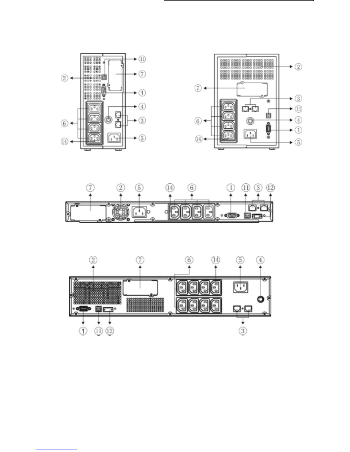
REAR VIEW
Spring 500/800/1100 T
Spring 1500/2000 T
Spring 500/800/1100 R
Spring 1500 RT
53

Spring 2200/3000 RT
Spring Battery Box
1. RS232 serial communication port
2. Cooling fans
3. Telephone/modem protection
54
4. Input Breaker
5. IEC mains input plug
6. IEC output sockets (max 10A)
7. Communication expansion slot
8. Battery expansion connector
9. IEC 16A output socket
10. Output Protection
11. USB Port
12. EPO
13. DC Breaker
14. Powershare socket

O PENING THE PACKAGING AND CHECKING THE CONTENTS
The first thing to do after opening the packaging is to check the contents
The packaging should contain the following:
UPS
USB cable
IEC 16A Power cord(Only for 2200/3000 RT)
IEC 10A connection cables
Tower stands(Only for RT models) + slide
assemblies (optional for RT models)
User’s manual + CD-ROM software + Warranty
Card
U
s
e
r
'
s
m
a
n
u
a
l
55
INSPECTING THE EQUIPMENT
LAC
NT
Inspect the UPS upon receipt. If the UPS has been damaged during shipment, keep the box and packing
material for the carrier. Notify the carrier and dealer immediately.
PLAC
EMEMENT
This UPS should be installed indoors with adequate airflow and free of contamination. Locate it in a clean and
indoor environment, free from moisture, flammable liquids, and direct sunlight. Maintain a minimum clearance of
4 inches (100mm); an ambient temperature range must be 0°C to 40°C (32°F to 104°F), and operating humidity
range must be 20% to 80% relative humidity (non-condensing).
CAUTION: The long term uses at ambient temperature in higher than 25qC which should reduce battery life. In
addition, place the UPS unit away from the monitor at least 20cm to avoid interference.
UPS SETUP
Spring family include T models that are design for tower purpose, R models that must be installed as a 19 inch
equipment rack and RT models that can be placed in tower configuration (with proper stands) or installed as a
19 inch equipment rack.
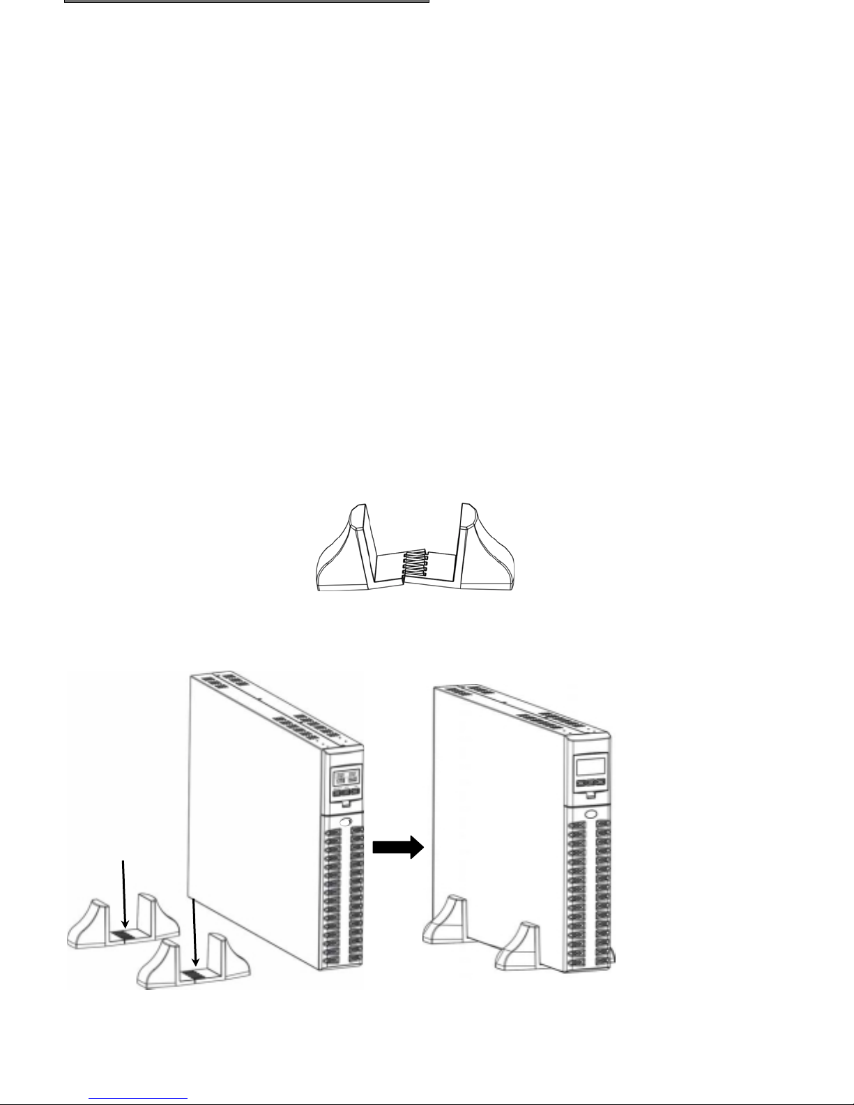
RT MODELS TOWER SETUP
The RT models are provided with the UPS stand necessary to stabilize the UPS when it’s positioned in vertically.
The UPS stand must be inserted to the bottom of the tower.
1. Put the two bracketes together
2. Slide down the UPS vertically and put two UPS stands at the end of the tower.
stands carefully.
Place the UPS into two
56

SPRING RT MODELS AND BATTERY BOX
1. Put the bracketes and the bracket extension together
2. Slide down the UPS and the battery box vertically and put two UPS stands at the end of the tower.
3. Place the UPS and battery box into two stands carefully.
57

RT MOD
MOD
ELS LCD DISPLAY COVER SETUP
The LCD display of the RT models can be rotate to adapt to rack or tower installation
Follow the below steps and charts, you can rotate the LCD display:
A. Rack To Tower
1. The UPS is placed by the level, pressing the key
B. Tower To Rack
1. If the UPS is placed vertically, pressing the key
2. The LCD display cover can be rotate at 90 angles
3. Tower configuration
2. The LCD display cover can be rotate at 90 angles
58
3. Rack configuration

R-RT MODELS RACK SETUP
Spring R and Spring RT can be installed in 19” racks. Use the following procedure to install UPS in a rack.
1. Align the mounting ears (optional for RT models) with screw holes on the side of the UPS.
2. Fix the slide to the rack enclosure with screws.
3. Insert UPS into the slide assemblies (optional for RT models) and lock it in the rack enclosure.
59

C ONNECTION
ONNECTION
ONNECTION
SET
UP
Connect the input of UPS with the mains power. Connect loads to to the sockets on the rear of the UPS with the
IEC-IEC cables or a cable with maximum length of 10 meters.
Notice: do not connect any loads that absorb more than 10A to the 10A IEC sockets. These loads should be
connected exclusively to the 16A IEC socket when this is available.
N ET /TEL CONNECTION
A telephone/modem or network cable can be connected to the modular RJ-45/RJ11 connectors located on the
rear of the UPS. Doing this can protect against overvoltages. A telephone extension cable is required for this
type of connection.
NOTICE: The connection is optional. The Net/Tel protection is active even when the UPS is turned off or
disconnected from mains power.
Warning: The device that protects against overvoltage on the telephone line may not work if it is not
installed correctly. Ensure that the telephone wall cable is inserted in the connector marked “IN” and
that the cable of the unit to be protected (telephone, modem, network card, etc.) is inserted in the
connector marked “OUT”.
Warning: The overvoltage protection device is only for indoor use. Do not connect telephone wires
during a storm.
NOTICE: The protection device limits the effects of an overvoltage but does not guarantee overall protection.
EMERGENCY POWER O FF (EPO) SET
Spring R and Spring RT series includes EPO port. The EPO power switch allows power to be shutdown
immediately and does not follow the shutdown procedure from any power management software.
Note: When EPO switch is reset, the equipment will not return to battery power until the UPS is manually
restarted. If pressing power switch to turn off UPS after EPO is activated, the UPS remains in Standby
mode .And the UPS will be restarted when pressing power switch to turn on the UPS again.
Follow the procedure to install the EPO switch as below.
1. Check the UPS is turned off.
2. Remove the EPO connector from the EPO port on the rear panel of UPS.
3. Connect isolated, normally-open, dry contacts (rated to handle 60Vdc maximum, 30Vac RMS maximum,
and 20mA maximum) across the EPO device to Pin 1 and Pin 2. Use non-shield wiring, size 18-22 AWG
(0.75 mm
4. Reconnect the EPO connector to the EPO port.
5. Verify that the externally-connected EPO switch is not activated to enable power to the UPS output
receptacles.
6. Plug in the UPS, then pressing ON power switch button to turn on the UPS.
7. Activate the external EPO switch to test the EPO function.
8. De-activate the external EPO switch and restart the UPS.
2
– 0.3mm2).
UP
60

A DDITIONAL BATTERY BOX INSTALLATION
Spring 2200 RT and 3000 RT models includes external battery port that allows to provide additional battery
runtime.
There is one external battery port for the UPS itself.
Caution: Connecting battery cable to external battery port may occur sparkle if adding up additional
battery.
Follow the procedure to install additional battery as below.
1. Connect the battery cable to the external battery port of the rear of Battery Box.
2. Then connect the supplied battery cable from battery box to the external battery port in the rear of UPS.
3. If continuing to add up battery box (total capacity max 120Ah), repeat above steps.
Note: When the battery box needs for making longer the backup time, UPS has to setup (with UPSTools
software) in order to calculate the right backup time and charging the battery properly. The setup must be made
when the UPS is turned on.
For this kind of battery box the value to inser is “9” [Ah] for each battery box connected.
For 2200/3000 RT models, in default condition, the charging current is 2A . But after setting the Nominal Battery
Capacity with UPSTools software, the charging current will change to 6A if the setting value is not less than 14.
61

TURN O N /OFF
To turn on/off the UPS, you should press the on/off switch three seconds at least.
Only for the first time you switch on: after about 30 sec., check that the UPS is working correctly by:
1. Simulating a black-out by removing the mains power cable
2. The load must continue to receive power, the “battery mode” indicator should light up and the UPS
should beep every 4 seconds.
3. Reconnect the power cable. Normal mains power operation should be restored.
C OOL START FUNCTION
Cool start function enables UPS to be started up when AC utility power is not available and battery is full
charged. Just simply press the On switch to turn on the UPS.
C HARGING
This UPS is shipped from the factory with its internal battery fully charged; however, some charge may be lost
during shipping. The battery should be recharged prior to use. Plug the UPS into an appropriate power supply
and allow the UPS to charge at least 8 hours.
62

FRONT PANEL
There are three buttons on the front panel ,which have been marked with “ON”, “OFF”,and “SELECT”.
LCD TOTAL VIEW
63

The detail description for the Part A(the left field of the LCD):
INPUT-VAC : the input voltage(unit: Volt)
ཱ INPUT-Hz: the input frequency(unit: Hz)
ི BATTERY-V: the total voltage of the battery (unit: Volt)
ཱི BATTERY-%: the estimated capacity of the battery in percentage
ུ BATTERY-MIN: the estimated battery remain time (unit: Minute)
The detail description for the Part B(the right field of the LCD):
OUTPUT-VAC: the output voltage(unit: Volt)
ཱ OUTPUT-Hz: the output frequency(unit: Hz)
ི LOAD-%: the output load in percentage
Part C and Part D indicate the state of the UPS. Refer to the LCD INDICATOR PANEL for the details.
64
LCD INDICATOR PANEL
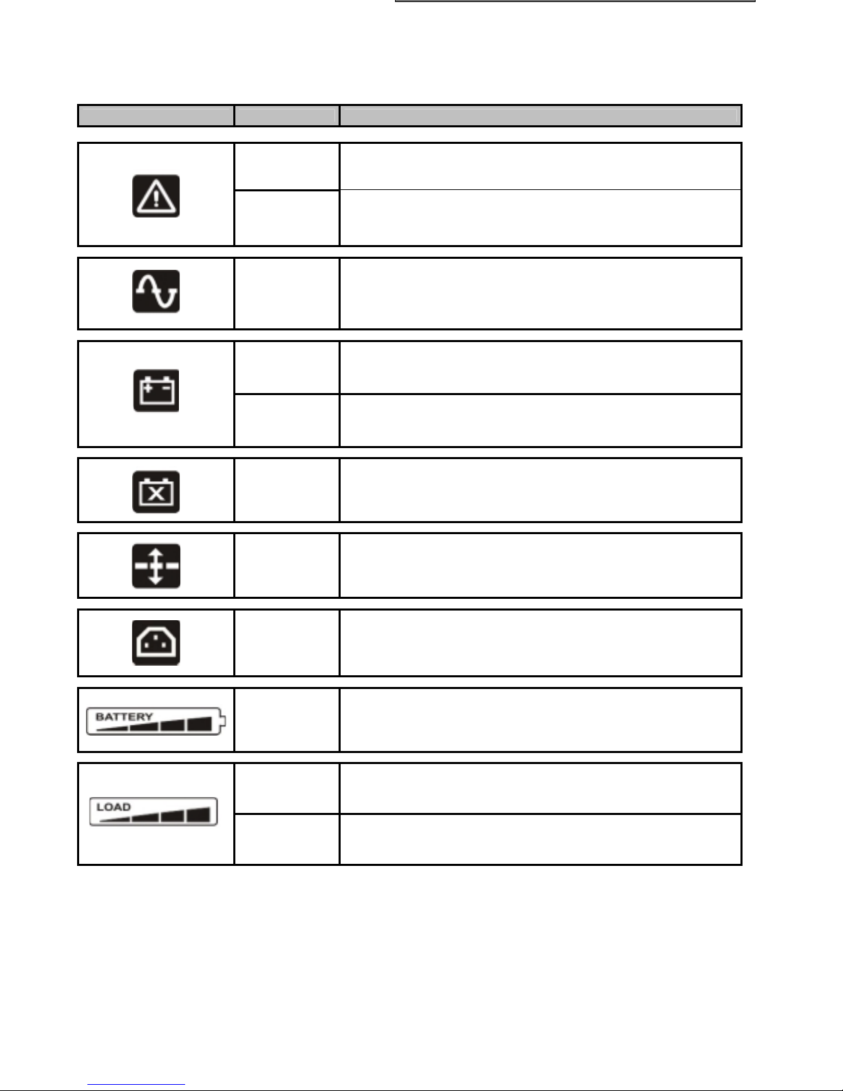
This chapter gives a detailed description of all indicator panel.
ICON STATUS DESCRIPTION
Steady Indicates a fault (see table 1)
Flashing The UPS is in standby mode
Steady The UPS is operating on mains power
Steady
Flashing
The UPS is operating in battery mode and will beep at regular
When operating off battery power, the UPS signals that it is
about to switch off due to end of discharge. In this state, it
beeps at regular intervals of 1 sec.
Steady Indicates battery failure
Steady AVR function is active
intervals.
Steady The power share socket is usable.
Active
Active
Represents the estimated percentage of battery charge
(see table 2)
Indicates the % of load applied to the UPS in relation to the
nominal value (see table 3)
Flashing The UPS is in overload condition
65

Table 1: Fault List
LCD Symbol In
Part A
Description Solution Advice
The UPS is over- loaded Check load level display and remove some load
1. Ensure the ambient temperature is below 40°C
The UPS is over temperature
2. Turn off the UPS and wait for a while to make it
cooling
1. Disconnect all loads and ensure nothing is
The UPS output is shortcircuit
Fan fails
output voltage is out of
range(inverter fails)
lodged in output receptacles
2. Ensure loads are not detective or shorted
internally
Please contact your local dealer for fan checking or
exchanging
Please contact your local dealer
UPS internal fault Please contact your local dealer
Table 2
Battery level
0%~20%
20%~40%
40%~60%
60%~80%
80%~100%
Tab. 3
Load level
flashing
0~5%
5~25%
25%~50%
50%~75%
75%~102%
>102%
After overloading, the UPS powers the loads and a hurried alarm will sound (1s on/1s off). By reducing the load
within the 100% threshold, the UPS returns to normal operating mode.
When the overload level is too high, the overload protection is activated and the UPS will be completely
shutdown.
To restore normal operation following failure due to overloading (continuous beep and load not powered), reduce
the load so that it falls within the 100% threshold. Hold the OFF button down until the continuous beep stops and
then release it. Wait until the UPS is completely shutdown and then switch on again.
66
LCD DISPLAY
DISPLAY
NFIGU
ION
The LCD display has two fields, left(Part A) and right(Part B). Left filed can shows the following measures:
“Input voltage”, “Input frequency”, “Battery voltage”, “Battery capacity percentage” and “Estimate battery
runtime”. For right field the measures available are: “Output volage”, “Output frequency” and “Load percentage”
Push the “SELECT” button to choose the field to set.
The first time that you push the “SELECT” button, the left field starts blinking. The second time that you push the
“SELECT” button the right field blinks, the third nothing blinks.
When the field are blinking push the “ON” button to confirm the field.
Push the “SELECT” button to choose measure required.
Push the “ON” button to confirm the measure choosed.
Configuration example:If you want the left field to display the “Estimate battery runtime”,and right display the
“Load percentage”, please follow the below procedure:
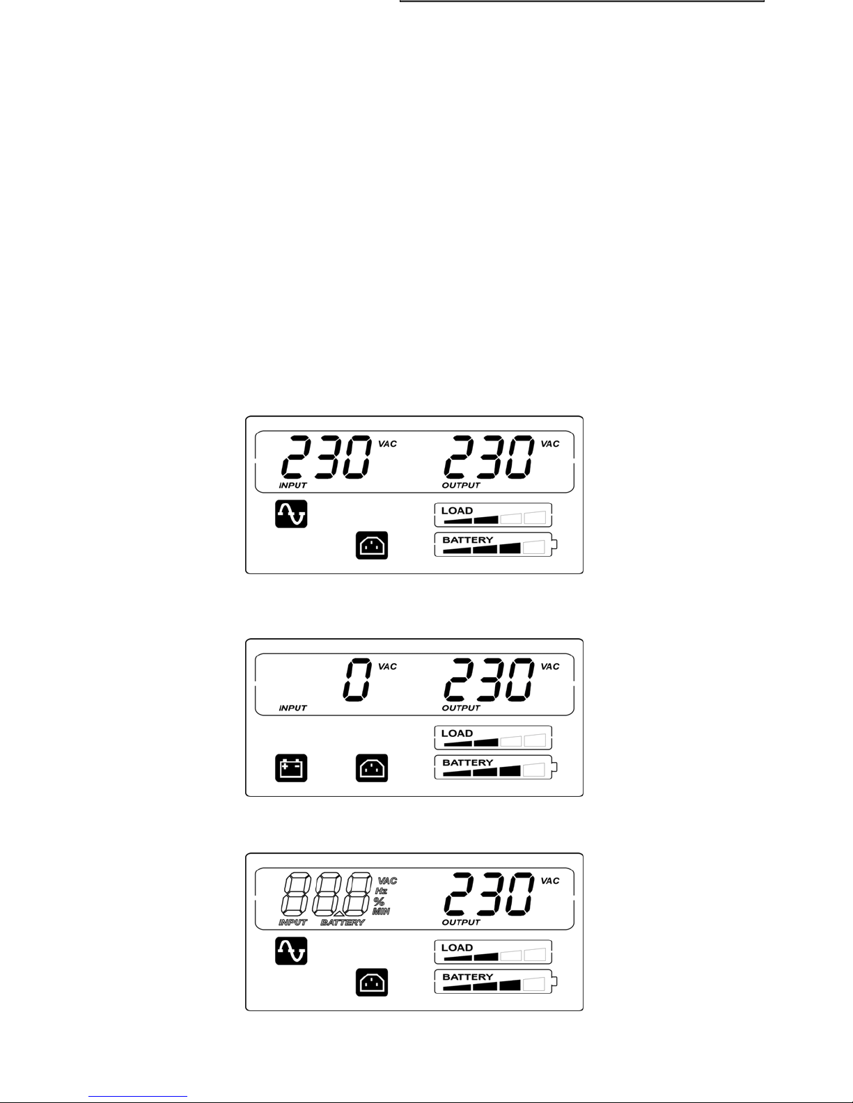
Step 1: Turn on the UPS, and the LCD displays the default measure, “Input voltage”in the left field and “Output
voltage”in the right field. The LCD will display as follows:
COCONFIGU
a) when the UPS is connected with the mains power
RATION
In utility condition
b) when the UPS is in battery mode:
In battery condition
Step 2: Push the “SELECT” button for 3 seconds, and the left field (the blank font) of the LCDwill blink.
67

Step 3: Push the “ON” button (confirm the left field), and the characters “INPUT”, “VAC”and corresponding
measure (the blank font) of the left field will blink.
Step 4: Push the “SELECT” button, and the characters “INPUT”, “Hz” and corresponding measure (the blank
font) of the left field will blink.
Step 5: Push the “SELECT” button again, and the characters “BATTERY”,“V” and corresponding measure (the
blank font) of the left field will blink.
Step 6: Continue to push the “SELECT” button, and the characters “BATTERY”, “%” and corresponding
measure (the blank font) of the left field will blink.
68
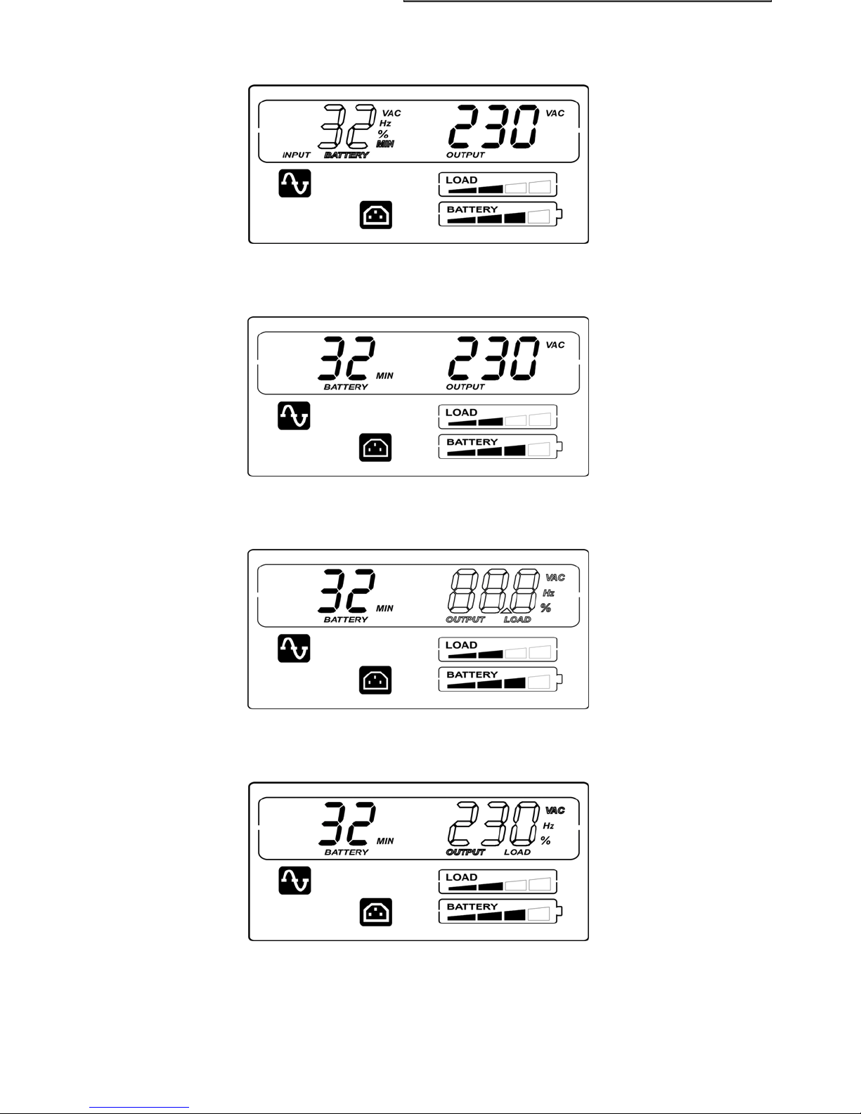
Step 7: Push the “SELECT” button, and at last the characters “BATTERY”, “MIN” and corresponding measure
(the blank font) of the left field will blink.
Step 8: Push the “ON” button (confirm this measure), then the measure of the left field is the “Estimate battery
runtime”.
Step 9: Push the “SELECT” button for 3 seconds, and the left field of the LCD will blink.
Push the “SELECT” button again, and the right field (the blank font) of the LCD will blink.
Step 10: Push the “ON” button, and the characters “OUTPUT” , “VAC” and corresponding measure (the blank
font) of the right field will blink.
69

Step 11: Push the “SELECT” button, and the characters “OUTPUT”, “Hz” and corresponding measure (the blank
font) of the right field will blink.
Step 12: Push the “SELECT” button, and the characters “LOAD”, “%” and corresponding measure (the blank
font) of the left field will blink.
Step 13: Push the “ON” button, then the measure of the right field is the “Load percentage”.
The configuration is complete.
NOTE: 1. If the configuration hasn’t been completed in 90 seconds,the UPS will exit the configuration
mode.
2. The LCD display has the memory function which could remember the last setting when UPS is
restarted.
70

B UZZER INDICATION
a) When keeping “ON”, “SELECT” or “OFF” button pressed for 1 to 3 seconds buzzer will beep;
b) If UPS is fault(because of over temperature or fan fail…) buzzer will beep steadily;
c) If battery bad or over charged, buzzer will beep steadily for warning;
d) If UPS is over load, buzzer will beep intermittently(1s on/1s off) for warning;
e) If UPS is in battery mode, buzzer will beep intermittently(1s on/4s off);
f) If UPS is in battery mode, and battery low, buzzer will beep intermittently(1s on/1s off) for warning;.
g) If battery is disconnected,after battery test, buzzer will beep intermittently(1s on/1s off) for warning;
h) When buzzer silence function is enabled (keeping “ON”botton pressed for over 3 seconds in battery
working condition), the buzzer will be mute, except for item b), item d) and item f).
i) If none of the above items occurs, the buzzer will be mute.
j) If UPS is in battery test process, the buzzer will beep 3 times(0.5s on / 0.5s off).
B ATTERY TEST
In line mode, keeping “ON” button pressed for over 5 seconds (three buzzer sound will be heard), UPS
performs battery test for 5 seconds(the default time).
In battery test process, both the icon “Line” and “Battery function” will be light.
The battery test process
71

RS232 PORT
The RS232 serial port allows the connection of a PC (COM port) by means of a pin-to-pin serial cable provided
(if a different cable is used, it should be of the pin-to-pin type with a max. length of 3 metres).
The computer interface in factory setup
port has the following characteristics as shown:
RS232 CONNECTOR
7
986
21345
. SIGNAL (factory setup)
1 Contact closed: UPS failure/Alarm
2 TXD
3 RXD/SD (remote shutdown)
4 Remote off
5 GND
6 +12Vdc (80mA)
7 PNP Signal
8 Contact closed: battery low pre-alarm
9 Contact closed: battery working
a) SD = With the UPS battery mode, shut down signal to switch off the UPS: +(5 ÷ 15) V DC for at least 20
seconds. Following this impulse the UPS shuts down immediately.
b) B.W. = contact closed in battery mode status (max. ratings:25mA +35Vdc Vce sat max: 1,5V @ 25mA)
c) B.L. = contact closed in battery low status (max. ratings:25mA +35Vdc Vce sat max: 1,5V @ 25mA)
d) UPS failure/Alarm = contact closed in UPS failure/Alarm status (max. ratings:25mA +35Vdc Vce sat max:
1,5V @ 25mA)
(d)
(a)
(c)
(b)
USB PORT
The USB port is used to establish communication between the UPS and a computer.
When the communication cable is installed, power management software(Watch & Save 3000) can exchange
data with the UPS. The software polls the UPS for detailed information on the status of the power environment. If
a power emergency occurs, the software initiates the saving of all data and an orderly shutdown of the
equipment.
C OMMUNICATION SLOT
All UPS come with an expansion slot for optional communication boards so that the unit is compatible with the
main communication standards.
Some examples:
Serial port duplexer
x Ethernet network agent with TCP/IP, HTTP and SNMP protocols
x RS232 + RS485 port with JBUS / MODBUS protocol
For more details on the options available, visit the manufacturer’s web site.
72

The CD-Rom provided includes two software programmes that allow the user to perform UPS monitoring, control
AND
CON
and configuration operations.
M ONITORING AND
The Watch & Save 3000 software ensures efficient and intuitive UPS management, by displaying all the
most important information such as input voltage, applied load, battery capacity, etc.
It can also automatically execute programmed shutdown/start-up operations, shutdown of the O.S., sending of emails, sms and network messages when specific user-selected events occur.
CON
TROL SOFTWARE
Installation Operations:
x Connect the UPS USB port to a USB port on the PC using the cable provided.
x Insert the CD-Rom and select the operating system required.
x Follow the installation instructions.
x For more detailed information on the installation and use of the software, refer to the software manual in the
Manuals folder on the CD-Rom provided.
Visit the manufacturer’s web site to check whether a more recent version of the software is available.
C ONFIGURATION SOFTWARE
UPSTools software allows the user to configure the UPS and provides a full view of the system parameters and
status through the USB port.
Refer to the paragraph UPS Configuration for a list of the possible configurations available.
Installation Operations:
x Connect the UPS USB port to the USB port on the PC using the cable provided.
x Follow the installation instructions given in the software manual in the UPSTools folder on the CD-Rom
provided.
Visit the manufacturer’s web site to check whether a more recent version of the software is available.
73

Audible Alarm Trouble Shooting
Problem Cause Solution
Sounding every
4 seconds
Sounding every
second
Continuously
sounding
Sounding every
second
Continuously
sounding
The UPS is on battery Check the input voltage
The battery is running low Save your work and turn off your equipment
The UPS fails Please contact your local dealer
Output overload Check load level indicator and remove some load
Battery may need to charge
or service
Replace the battery
General Trouble Shooting
The UPS is not
on when power
switch is
pressed
UPS could not
provide power to
the load
Battery has
reduced backup
time
The UPS fault
indicator
lights on
The battery bad
indicator
lights on
Connected
equipment’s
lose power while
connected to the
UPS
The UPS is
beeping
continuously
Buttons does
not work
The power cord is not
connected correctly
The wall outlet may be
faulty
The UPS output may shortcircuit or overload
Internal fuse may be blown Please contact your local dealer
Power is not presents on
one of the output sockets
Power is not presents on
any output sockets
Battery is not charged Re-charge the battery at least 4 hours
Battery may not able to
hold a full charge due to
age.
The UPS fails
The battery is bad
The UPS may be overloaded
The UPS may be failed Please contact your local dealer
The UPS is in fault
condition
1. The UPS is in green
mode
2. Button is Broken
Check the power cord connection
Please contact your local qualified electrician
1. Disconnect all loads and ensure nothing is lodged in
output receptacles
2. Ensure loads are not detective or shorted internally
Check the output fuse
1. Check the connected cable
2. Ensure the load does not exceed the maximum rating of
UPS
1. Recharge the battery at least 8 hours
2. Replace Battery
Save your work and turn off equipment. And refer to the
LCD INDICATOR PANEL for the details.
1. Check the battery connection
2. Please contact your local dealer to order new battery,
and replace the bad battery
Check the load status
Check the audible alarms condition table
1. Wait for a while and try again
2. Please contact your local dealer
74

When the Bad Battery indicator lights and there is a continuous sounding, the battery may need to be
r
replaced. Please check the battery connection or contact your local dealer to order new battery.
CAUTION: A battery can present a risk of electrical shock and high short circuit current. The following
precautions should be observed before replacing the batteries.
1. Turn off the UPS and disconnect the utility power cord from the wall outlet.
2. Remove rings, watches, and other metal objects.
3. If the battery replacement kit is damaged in anyway or shows signs of leakage, contact your dealer
immediately.
Note: If you are not qualified service personnel to replace the battery, do not attempt to open the batte
Please call local dealer or distributor immediately.
Recycle the used battery:
Never dispose the batteries in a fire. It may explode.
Do not open or mutilate the batteries. Released electrolyte is harmful to the skins and eyes. It may be toxic. A
battery can present a risk of electrical shock and high short circuit current.
To recycle properly the used battery, please do not discard the UPS, battery box, and batteries into the trash bin.
Please follow your local laws and regulations; you may contact your local recycling waste center for further
information to dispose properly of the used UPS, battery box, and batteries.
Follow the steps and charts below to replace batteries:
SPRING T
1. Remove the UPS front panel by pulling on
both ends.
2. Disconnect the battery cable from the UPS.
Remove the battery plate retaining battery
stably, then unscrew the battery bracket from
the UPS
3. Grasp the battery paper and pull it out from
the case.
4. Slide the new batteries into the UPS.
5. Reconnect the battery cable and screw up the
battery bracket.
6. Close and reinstall the front panel back to
UPS.
75

SPRING R
1. Remove the UPS front panel by pulling on both ends.
2. Disconnect the battery cable from the UPS, then unscrew the battery bracket from the UPS
3. Remove the battery plate retaining battery stably.
4. Pull the battery out onto flat area
5. Slide the new batteries into UPS.
6. Reconnect the battery cable and screw up the battery bracket.
7. Close and reinstall the front panel back to UPS.
76

SPRING RT
1. Remove the UPS front panel by pulling on both ends.
2. Unscrew the battery bracket from the UPS. Remove the battery plate retaining battery stably.
3. Disconnect the battery cable from the UPS.
4. Pull the battery out onto flat area
5. Slide the new batteries into UPS.
6. Reconnect the battery cable and screw up the battery bracket.
7. Close and reinstall the front panel back to UPS
77

NOMINAL
POWER
Spring T
500 800 1100 1500 2000
VA 500 800 1100 1500 2000
Watt 350 540 740 1050 1350
Nominal Voltage 230 VAC
(1)
INPUT
OUTPUT
OVERLOAD
RATING
TRANSFER TIME
BATTERY
PHYSICAL
Mains voltage range
Frequency Range 50/60Hz Autoselection
Voltage Regulation (Batt. Mode) 230V +5% ,-10%
Frequency 50/60Hz Autoselection
Frequency Regulation (Batt.
Mode)
Waveform Pure Sinewave
Line Mode
Battery Mode
Typical 4-msec. typical 6-msec.max.
Battery Number 1x12V 2 x12V 2 x12V 4 x12V 4 x12V
Dimension (LxHxD)
UPS
mm
Net weight (kg) 7 11 11 18 18
>110% alarm and fault after 3 minutes
>110 % alarm and fault after 30 seconds
110X235X383 160X235X425
160VAC ± 3%
294VAC ± 3%
(1)
±0.1Hz
>150% fault after 40 cycles
>120% fault after 40 cycles
ENVIRON-
MENT
INTERFACE
OTHER
Battery box Not availlable
Operating Environment 0- 40°C, 20 to 80% relative humidity (non-condensing)
Noise Level Less than 50dBA
RS-232 Yes
USB Yes
Communication expansion slot Yes
EPO Not availlable
Protection
Safety certifications GS-TUV / CE
EMC compliance EN55022 CLASSA
Excessive discharge of batteries – overcurrent – short circuit – overvoltage –
undervoltage – thermal
78

500 800 1100 1500 2200 3000
Spring R Spring RT
NOMINAL
POWER
INPUT
OUTPUT
OVERLOAD
RATING
TRANSFER
TIME
BATTERY
VA 500 800 1100 1500 2200 3000
Watt 350 540 740 1050 1540 2100
±0.1Hz
(1)
(1)
438X87.9X582
(19”x2Ux582)
Nominal Voltage 230 VAC
Mains voltage range
Frequency Range 50/60Hz Autoselection
Voltage Regulation (Batt.
Mode)
Frequency 50/60Hz Autoselection
Frequency Regulation (Batt.
Mode)
Waveform Pure Sinewave
Line Mode
Battery Mode
Typical 4-msec. typical 6-msec.max.
Battery Number 2x6V 3x6V 4x6V 4 x12V 8x12V 8x12V
UPS
Dimension
(LxHxD) mm
Net weight (kg) 12 13 15 29 31 32
438X44.3X460
(19”x1Ux460)
>110% alarm and fault after 3 minutes
>110 % alarm and fault after 30 seconds
160VAC ± 3%
294VAC ± 3%
230V +5% ,-10%
>150% fault after 40 cycles
>120% fault after 40 cycles
Nominal voltage Not availlable Not availlable 96 V
PHYSICAL
ENVIRON-
MENT
INTERFACE
OTHER
Battery
Box
Operating Environment 0- 40°C, 20 to 80% relative humidity (non-condensing)
Noise Level Less than 50dBA
RS-232 Yes
USB Yes
Communication expansion slot Yes
EPO Yes
Protection
Safety certifications GS-TUV / CE
EMC compliance EN55022 CLASSA
Nominal Not availlable Not availlable 9 Ah
Battery Number Not availlable Not availlable 8
Dimension
(WxHxD) mm
Net weight (kg) Not availlable Not availlable 30
Excessive discharge of batteries – overcurrent – short circuit – overvoltage – undervoltage
Note:
(1)
changeable by UPSTools (200/208220/230/240VAC)
Not availlable Not availlable 438X87.9X582
– thermal
79
 Loading...