

Page 1
OPERATOR’S MANUAL
INCLUDING:ĂOPERATION,ĂINSTALLATIONĂ&ĂMAINTENANCE
SECTION M10
MANUAL 129
Released: 02-07-94
Revised: 09-01-00
MODELS RS2( )A–( ) and RS2( )A–( )–EU
RANDOM ORBITAL SANDERS
12,000 R. P. M.
ARO is not responsible for customer modification of tools for applications on which ARO
was not consulted.
IMPORTANT SAFETY INFORMATION ENCLOSED.
READ THIS MANUAL BEFORE OPERATING TOOL.
IT IS THE RESPONSIBILITY OF THE EMPLOYER TO PLACE THE INFORMATION
IN THIS MANUAL INTO THE HANDS OF THE OPERATOR.
FAILURE TO OBSERVE THE FOLLOWING WARNINGS COULD RESULT IN INJURY.
PLACING TOOL IN SERVICE
• Always operate, inspect and maintain this tool
in accordance with American National
Standards Institute Safety Code for Portable
Air Tools (ANSI B186.1).
• For safety, top performance, and maximum
durability of parts, operate this tool at 90 psig
(6.2 bar/620 kPa) maximum air pressure at the
inlet with 5/16” (8 mm) inside diameter air
supply hose.
• Always turn off the air supply and disconnect
the air supply hose before installing, removing
or adjusting any accessory on this tool, or
before performing any maintenance on this
tool.
• Do not use damaged, frayed or deteriorated
air hoses and fittings.
• Be sure all hoses and fittings are the correct
size and are tightly secured. See Dwg.
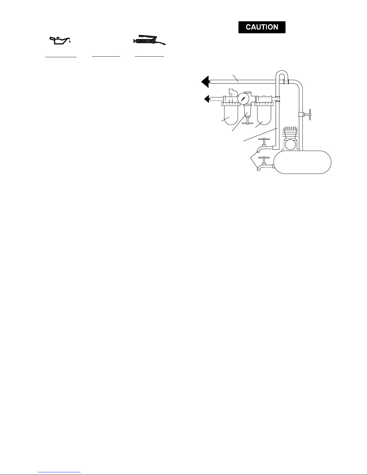
TPD905–1 for a typical piping arrangement.
• Always use clean, dry air at 90 (6.2 bar/
620 kPa) psig maximum air pressure. Dust,
corrosive fumes and/or excessive moisture
can ruin the motor of an air tool.
• Do not lubricate tools with flammable or
volatile liquids such as kerosene, diesel or jet
fuel.
• Do not remove any labels. Replace any
damaged label.
USING THE TOOL
• Always wear eye protection when operating or
performing maintenance on this tool.
• Always wear hearing protection when
operating this tool.
• Keep hands, loose clothing and long hair
away from rotating end of tool.
• Anticipate and be alert for sudden changes in
motion during start up and operation of any
power tool.
• Keep body stance balanced and firm. Do not
overreach when operating this tool. High
reaction torques can occur at or below the
recommended air pressure.
• Tool accessories may continue to rotate
briefly after throttle is released.
• Air powered tools can vibrate in use.
Vibration, repetitive motions or uncomfortable
positions may be harmful to your hands and
arms. Stop using any tool if discomfort,
tingling feeling or pain occurs. Seek medical
advice before resuming use.
• Use accessories recommended by ARO.
• This tool is not designed for working in
explosive atmospheres.
• This tool is not insulated against electric
shock.
The use of other than genuine ARO replacement parts may result in safety hazards, decreased tool
performance, and increased maintenance, and may invalidate all warranties.
Repairs should be made only by authorized trained personnel. Consult your nearest ARO Authorized
Servicenter.
For parts and service information, contact your local ARO distributor, or the Customer Service Dept. of the Ingersoll–Rand
Distribution Center, White House, TN at PH: (615) 672–0321, FAX: (615) 672–0801.
ARO Tool Products
Ingersoll–Rand Company
1725 U.S. No. 1 North D P.O. Box 8000 D Southern Pines, NC 28388–8000
E 2000 INGERSOLL–RAND COMPANY D PRINTED IN U.S.A.
Page 2
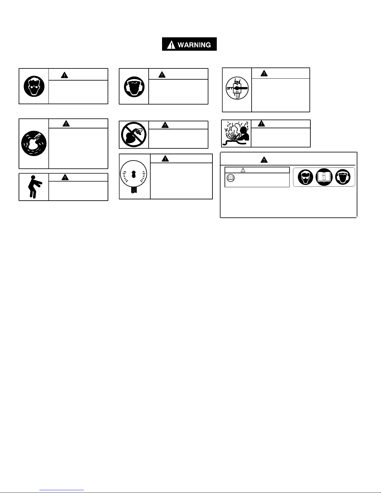
W ARNING LABEL IDENTIFICATION
FAILURE TO OBSERVE THE FOLLOWING WARNINGS COULD RESULT IN INJURY.
M10
129
WARNING
Always wear eye protection
when operating or performing maintenance on this
tool.
WARNING
Air powered tools can vibrate
in use. Vibration, repetitive
motions or uncomfortable positions may be harmful to your
hands and arms. Stop using
any tool if discomfort, tingling
feeling or pain occurs. Seek
medical advice before resuming use.
90 psig
(6.2bar/620kPa)
WARNING
Always wear hearing
protection when operating
this tool.
WARNING
Do not carry the tool by
the hose.
Operate at 90 psig (6.2 bar/
620 kPa) Maximum air pressure.
WARNING
Keep body stance balanced
and firm. Do not overreach
when operating this tool.
SANDER SPECIFIC WARNINGS
• Use only a sanding pad, buffing wheel or
polishing bonnet with these tools. Do not use
any grinding wheel, bur or metal removing
accessory other than a sanding pad with
these tools. Never use an accessory having a
maximum operating speed less than the free
speed of the Sander in which it is being used.
• These Sanders will operate at the free speed
specified on the nameplate if the air supply
line furnishes 90 psig (6.2 bar/620 kPa) air
pressure at the tool. Operation at higher air
pressure will result in excessive speed.
• Do not operate this Sander away from the
work surface.
• Check for excessive speed and vibration
before operating.
• Do not use this tool if actual free speed
exceeds the nameplate rpm.
• Never exceed the rated rpm of tool.
WARNING
• Repeated prolonged operator exposure to
• When using a pad having a shank, insert the
• Always use the recommended ARO Guard
WARNING
Always turn off the air supply and disconnect the air
supply hose before installing, removing or adjusting
any accessory on this tool,
or before performing any
maintenance on this tool.
WARNING
Do not use damaged, frayed
or deteriorated air hoses
and fittings.
WARNING
WARNING
Read the manual before
operating this tool.
Operate at 90 psig/6.2 bar max.
PN 48176–1 LABEL
(NON–EU MODELS)
This label must appear on the tool at all times. If it is lost or
damaged, a replacement label is available at no cost.
vibrations which may be generated in the use
of certain hand–held tools may produce
Raynaud’s phenomenon, commonly referred
to as Whitefinger disease. The phenomenon
produces numbness and burning sensations
in the hand and may cause circulation and
nerve damage as well as tissue necrosis.
Repetitive users of hand–held tool who
experience vibrations should closely monitor
duration of use and their physical condition.
shank to full depth in the collet. When using a
pad on a threaded arbor, make certain the
flange nut is tightened securely. Check the
tightness of the collet nut or flange nut before
operating a Sander to make certain it will not
loosen during operation.
furnished with the Sander.
PN 49883 LABEL
(–EU MODELS)
2
Page 3
LUBRICATION
Where Used
‘‘O” Rings & Lip Seals 36460 4 oz. Stringy
Gears and Bearings 33153 5 lb. ‘‘EP” – NLGI
ARO Part # Description
Lubricant
#1 Grease
M10
129
Do not mark any nonmetallic surface on this tool
with customer identification codes. Such actions
could affect tool performance.
MAIN LINES 3 TIMES
AIR TOOL INLET SIZE
TO
AIR
SYSTEM
Always use an air line lubricator with these tools.
We recommend the following Filter–Lubricator–
Regulator Unit:
ARO Model P29231–110 plus 100067 Gauge
After each 160 hours of operation, inject one or two
strokes of ARO Part #33153 grease through the end of
the spindle (27) to lubricate the needle bearing which is
in the end of the counterbalance (26). The sanding pad
(29) must be removed from the spindle to allow injection
of the grease.
TO
AIR
TOOL
LUBRICATOR
REGULATOR
BRANCH LINE 2 TIMES
AIR TOOL INLET SIZE
DRAIN REGULARLY
FILTER
COMPRESSOR
(Dwg. TPD905–1)
3
Page 4
M10
129
3
2
5
4
14
n 15
n 16
17
19
18
20
n 21
FACE WITH ROUNDED O.D. ON THIS SIDE
1
67
10
8n 9
11 [NOT USED ON MODELS RS2( )A–VLV]
31 [USED ON MODELS RS2( )A–VLV]
12 [USED ON MODELS RS2( )A–C( )V]
13 [USED ON MODELS RS2( )A–PS( )]
INSTALL RETAINING RING (15) AS SHOWN.
(BOWED AWAY FROM BEARING)
22
n 16
23
24
25
26
n 27
n 28
29
NOT SHOWN
K 49973 DISPOSABLE BAG (3)
K 49975 BAG COVER (STANDARD MODELS & EU MODELS)
K 49979 ADAPTER
K 49982 HOSE
K 49986 COLLAR
EXTRA COST ITEMS (NOT INCLUDED WITH TOOL)
48869 SPANNER WRENCH
49799 GRIP RING (3.00” DIA.)
49801 GRIP RING (2.58” DIA.)
n INCLUDED IN SERVICE KIT NO. 49837.
K INCLUDED WITH MODELS RS2( )A–VLV–( ) ONL Y.
(ATP–40)
4
Page 5
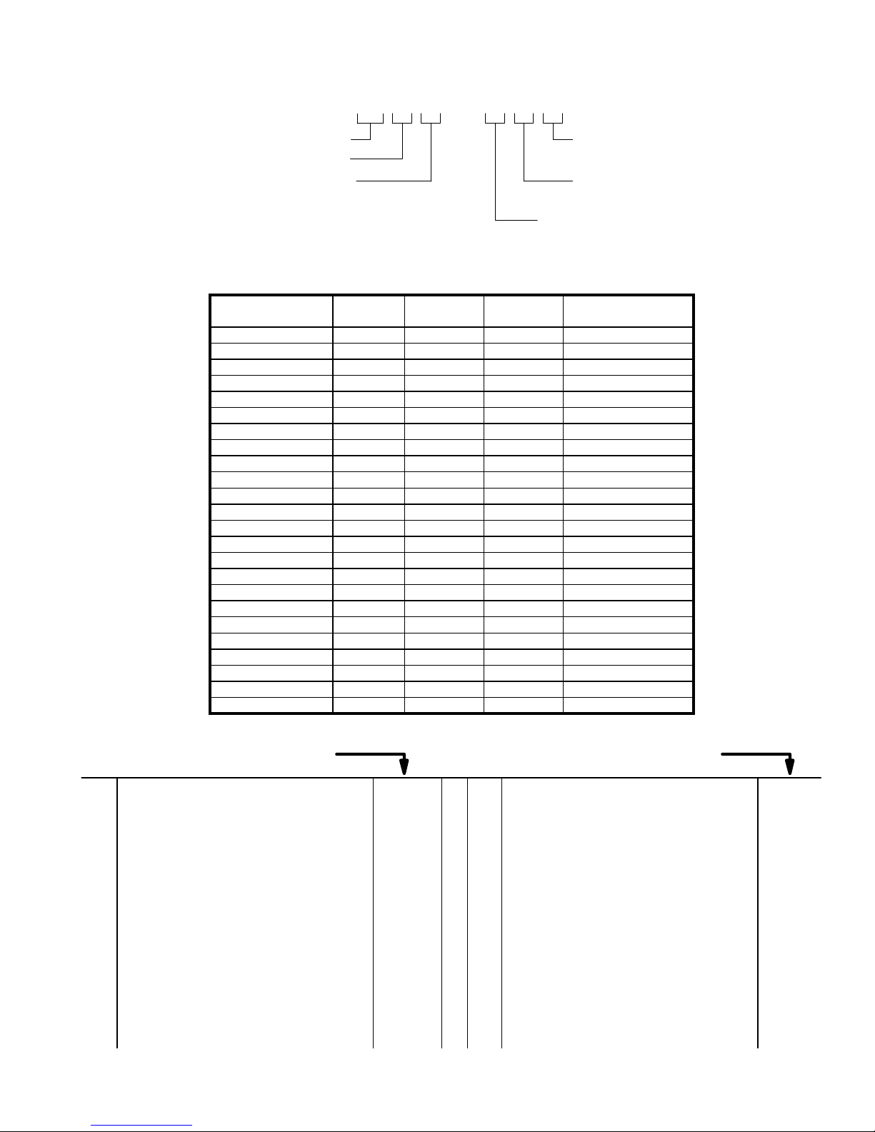
RANDOM SANDER
HORSEPOWER (.2)
SANDING PAD SIZE
3 = 3–1/2”
5 = 5”
6 = 6”
M10
129
MODEL NUMBER IDENTIFICATION
RS 2 X A– XXX
PAD TYPE
D = DUCK FACE
V = VINYL FACE
SHROUD
L = LONG
S = SHORT
SANDER TYPE
C = CENTRAL VACUUM
P = PLAIN
V = VENTURI
MODEL
NUMBER
LEVER
(ITEM 3)
SHROUD
(ITEM 14)
PAD
(ITEM 29)
PAD
DESCRIPTION
RS23A–CLV 48274–1 04334025 04334009 3–1/2” VINYL FACE
RS23A–CLV–EU 49936 04334025 04334009 3–1/2” VINYL FACE
RS23A–PLV 48274–1 04334025 04334009 3–1/2” VINYL FACE
RS23A–PLV–EU 49936 04334025 04334009 3–1/2” VINYL FACE
RS23A–VLV 48274–1 04334025 04334009 3–1/2” VINYL FACE
RS23A–VLV–EU 49936 04334025 04334009 3–1/2” VINYL FACE
RS25A–CLV 48274–1 48876 49096 5” VINYL FACE
RS25A–CLV–EU 49936 48876 49096–1 5” VINYL FACE
RS25A–CSV 48274–1 48266–1 49096 5” VINYL FACE
RS25A–CSV–EU 49936 48266–1 49096–1 5” VINYL FACE
RS25A–PSD 48274–1 48266–1 49877 5” DUCK FACE
RS25A–PSV 48274–1 48266–1 49094 * 5” VINYL FACE
RS25A–PSV–EU 49936 48266–1 49094–1 * 5” VINYL FACE
RS25A–VLV 48274–1 48876 49096 5” VINYL FACE
RS25A–VLV–EU 49936 48876 49096–1 5” VINYL FACE
RS26A–CLV 48274–1 48878 49099 6” VINYL FACE
RS26A–CLV–EU 49936 48878 49099–1 6” VINYL FACE
RS26A–CSV 48274–1 48266–1 49099 6” VINYL FACE
RS26A–CSV–EU 49936 48266–1 49099–1 6” VINYL FACE
RS26A–PSD 48274–1 48266–1 49880 6” DUCK FACE
RS26A–PSV 48274–1 48266–1 49879 6” VINYL FACE
RS26A–PSV–EU 49936 48266–1 49879–1 6” VINYL FACE
RS26A–VLV 48274–1 48878 49099 6” VINYL FACE
RS26A–VLV–EU 49936 48878 49099–1 6” VINYL FACE
MODELS WITH –EU SUFFIX ARE “EC” COMPLIANT MODELS *GOLD COLOR CODED SPINDLE
PART NUMBER FOR ORDERING PART NUMBER FOR ORDERING
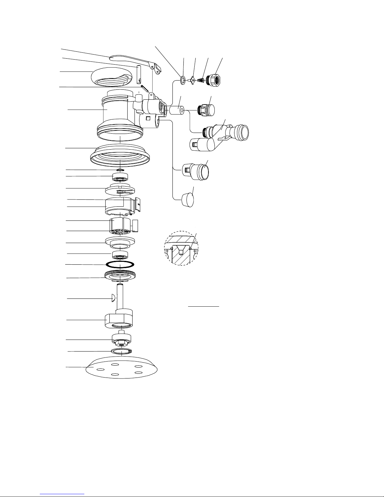
1 Housing (includes pin) 49816–1. . . . . . . . . . . . . . . .
2 Valve Stem 48065–2. . . . . . . . . . . . . . . . . . . . . . . . . .
3 Lever See table. . . . . . . . . . . . . . . . . . . . . . . . . . . . . . .
4 Roll Pin Y178-134. . . . . . . . . . . . . . . . . . . . . . . . . . . . .
5 Grip Ring 49798. . . . . . . . . . . . . . . . . . . . . . . . . . .
6 Seat 48071. . . . . . . . . . . . . . . . . . . . . . . . . . . . . . .
7 Tip Valve 48070. . . . . . . . . . . . . . . . . . . . . . . . . . .
8 Spring 32858. . . . . . . . . . . . . . . . . . . . . . . . . . . . . .
9 Inlet Adapter 49824. . . . . . . . . . . . . . . . . . . . . . . .
10 Muffler Tube 48263–1. . . . . . . . . . . . . . . . . . . . . . . . .
11 Muffler 49818. . . . . . . . . . . . . . . . . . . . . . . . . . . . . .
12 Vacuum Adapter 49802. . . . . . . . . . . . . . . . . . . . .
13 Tapered Plug 49821. . . . . . . . . . . . . . . . . . . . . . . .
14 Shroud See table. . . . . . . . . . . . . . . . . . . . . . . . . . . . .
15 Retaining Ring 44533. . . . . . . . . . . . . . . . . . . . . . .
16 Bearing (2 req’d) 48169–1. . . . . . . . . . . . . . . . . . . . .
17 Rear End Plate 48872. . . . . . . . . . . . . . . . . . . . . .
18 Cylinder (includes roll pin) 49815. . . . . . . . . . . . .
19 Seal 49819. . . . . . . . . . . . . . . . . . . . . . . . . . . . . . . .
20 Rotor 48253–1. . . . . . . . . . . . . . . . . . . . . . . . . . . . . . .
21 Blade (5 req’d) 48254–1. . . . . . . . . . . . . . . . . . . . . . .
22 Front End Plate 48871. . . . . . . . . . . . . . . . . . . . . .
23 O–Ring Y325-223. . . . . . . . . . . . . . . . . . . . . . . . . . . . .
24 Lock Ring 48257–1. . . . . . . . . . . . . . . . . . . . . . . . . . .
25 Key 39442. . . . . . . . . . . . . . . . . . . . . . . . . . . . . . . .
26 Counterbalance (includes needle bearing)
for 3–1/2” pad models 49808–3. . . . . . . . . . . . . .
for 5” pad models 49808–5. . . . . . . . . . . . . . . . . .
for 6” pad models 49808–6. . . . . . . . . . . . . . . . . .
27 Spindle Assembly (includes bearing) 49807. . . .
28 Retaining Ring Y147–125. . . . . . . . . . . . . . . . . . . . . . .
29 Sanding Pad See table. . . . . . . . . . . . . . . . . . . . . . . .
30 Wrench (not shown) 30131–2. . . . . . . . . . . . . . . . . .
31 Eductor Assembly 49976. . . . . . . . . . . . . . . . . . . .
Service Kit: includes items 8, 15, 16, 21,
27 and 28 49837. . . . . . . . . . . . . . . . . . . . . . . . . .
5
Page 6

DISASSEMBLY/ASSEMBLY INSTRUCTIONS
Always wear eye protection when operating or performing maintenance on this tool.
Always turn off the air supply and disconnect the air
supply hose before installing, removing or adjusting
any accessory on this tool or before performing any
maintenance on this tool.
• Never apply excessive pressure by a holding device which
may cause distortion of a part.
• Apply pressure evenly to parts which have a press fit.
• Apply even pressure to the bearing race that will be press
fitted to the mating part.
• Use correct tools and fixtures when servicing this tool.
• Don’t damage ‘‘O” rings when servicing this tool.
• Use only genuine ARO replacement parts for this tool.
When ordering, specify part number, description, tool model number and serial number.
MOTOR DISASSEMBLY
– Remove sanding pad (24).
– Remove retaining ring (28).
– Remove spindle assembly (27) (includes bearing). NOTE:
Do not attempt to remove bearing from spindle.
– Remove lock ring (24) and pull motor and seal (19) from
housing.
– Remove retaining ring (15).
– Using special brass blocks to fit around o.d. of cylinder,
clamp around cylinder and press shaft of counterbalance
thru bearing (16) and end plate (17).
– Remove blades (21), rotor (20) and key (25).
– Remove end plate (22) and bearing (16).
MOTOR ASSEMBLY
– Grease and assemble ‘‘O” ring (23) to lock ring (24).
– Assemble lock ring (24) over counterbalance (26).
– Assemble bearing (16) into end plate (22), pressing on out-
er race of bearing.
– Assemble end plate (22) onto shaft of counterbalance,
pressing on inner race of bearing.
– Install key (25) in key slot.
– Assemble rotor (20) to counterbalance, aligning keyway to
key (25).
– Assemble five rotor blades (21) to rotor slots.
– Assemble cylinder (18) over rotor, aligning roll pin in cylin-
der with slot in end plate.
M10
129
– Assemble bearing (16) into end plate (17), pressing on out-
er race of bearing.
– Assemble end plate (17), with bearing (16), to counterbal-
ance, pressing on inner race of bearing. NOTE: Align slot in
end plate with roll pin in cylinder.
– Install retaining ring (15) to groove in counterbalance, with
bow in ring positioned as shown on parts illustration page.
– Assemble seal (19) to grooves in cylinder.
– Assemble motor to housing, aligning seal (19) with air inlet.
– Tighten lock ring (24), securing motor assembly.
– Lubricate needle bearing, contained in counterbalance,
with ARO 33153 grease.
– Assemble spindle assembly (27) to counterbalance, se-
curing with retaining ring (28).
– Assemble sanding pad (29) to tool and tighten securely.
THROTTLE DISASSEMBLY
– Remove vacuum adapter (12)(if applicable) by pressing in
on tabs and pulling vacuum adapter out.
– Models RS2( )A–VLV: Remove eductor assembly (31)(if
applicable). To remove, unthread upper section, press in
on tabs of lower section and pull assembly from housing.
– Remove inlet adapter (9), releasing spring (8) and valve
(7). NOTE: Do not remove seat (6) unless damage is evident.
– Remove muffler (11), releasing muf fler tube (10).
– To remove valve stem (2), remove roll pin (4) and lever (3).
THROTTLE ASSEMBLY
– Coat valve stem (2) with ARO 29665 spindle oil and as-
semble into housing with hole in valve stem in line with
housing to accept valve (7).
– Assemble seat (6) into housing with rounded corners into
housing first.
– Coat valve (7) with ARO 29665 spindle oil and assemble
into housing, securing valve stem (2).
– Assemble spring (8) into housing.
– Assemble inlet adapter (9) to housing, securing throttle
components.
– Assemble lever (3) to housing, securing with roll pin (4).
– Assemble vacuum adapter (12) or plug (13) to housing. To
assemble vacuum adapter, push into housing until tabs on
vacuum adapter snap into slots in housing. To assemble
plug, push into housing until it is flush with port opening.
– Models RS2( )A–VLV: Assemble eductor assembly (31) to
housing. To assemble, insert tapered section of eductor
assembly into housing while aligning threaded section with
housing. Using a wrench on flats, tighten threaded section
securely. Tabs will snap into slots in housing.
6
Page 7

M10
129
7
Page 8

PN 49999–451
 Loading...