


ARO.
OPERATOR’S MANUAL
INCLUDING: OPERATION, INSTALLATION & MAINTENANCE
MANUAL
150
F
Part No.
Revised:
49999-217 E
01-16-98
P
SERIES GH03A AND GHX03A GRINDERS
Series GH03A and GHX03A Grinders are designed for close-quarter work in the metal fabricating
industry, shipyards, pipe fabrication, die and mold manufacturing and limited space applications.
They are particularly good where conduits, pipes, ducts etc. pass through bulkheads or frames.
These small Grinders are very efficient at grinding weld bead and leaving a fine finish.
ARO is not responsible for customer modification of tools for applications on which ARO was not
consulted.
IMPORTANT SAFETY INFORMATION ENCLOSED.
READ THIS MANUAL BEFORE OPERATING TOOL.
IT IS THE RESPONSIBILITY OF THE EMPLOYER TO PLACE THE INFORMATION
IN THIS MANUAL INTO THE HANDS OF THE OPERATOR.
FAILURE TO OBSERVE THE FOLLOWING WARNINGS COULD RESULT IN INJURY.
PLACING TOOL IN SERVICE
.
Always operate, inspect and maintain this tool in
accordance with American National Standards
Institute Safety Code for Portable Air Tools
(ANSI B186.1).
.
For safety, top performance, and maximum durability
of parts, operate this tool at 90 psig (6.2 bar/620 kPa)
maximum air pressure at the inlet with 5/16” (8 mm)
inside diameter air supply hose.
.
Always turn off the air supply and disconnect the air
supply hose before installing, removing or adjusting
any accessory on this tool, or before performing any
maintenance on this tool.
.
Do not use damaged, frayed or deteriorated air hoses
and fittings.
.
Be sure all hoses and fittings are the correct size and
are tightly secured. See Dwg. TPD905-1 for a typical
piping arrangement.
l
Always use clean, dry air at 90 psig maximum air
pressure. Dust, corrosive fumes and/or excessive
moisture can ruin the motor of an air tool.
.
Do not lubricate tools with flammable or volatile liquids such as kerosene, diesel or jet fuel.
.
Do not remove any labels. Replace any damaged label.
USING THE TOOL
.
.
.
.
.
.
.
.
.
.
Always wear eye protection when operating or
performing maintenance on this tool.
Always wear hearing protection when operating this
tool.
Keep hands, loose clothing and long hair away from
rotating end of tool.
Anticipate and be alert for sudden changes in motion
during start up and operation of any power tool.
Keep body stance balanced and firm. Do not overreach when operating this tool. High reaction torques
can occur at or below the recommended air pressure.
Tool accessories may continue to rotate briefly after
throttle is released.
Air powered tools can vibrate in use. Vibration, repetitive motions or uncomfortable positions may be
harmful to your hands and arms. Stop using any tool
if discomfort, tingling feeling or pain occurs. Seek
medical advice before resuming use.
Use accessories recommended by ARO.
This tool is not designed for working in explosive
atmospheres.
This tool is not insulated against electric shock.
The use of other than genuine ARO replacement parts may result in safety hazards, decreased tool performance, and
increased maintenance, and may invalidate all warranties.
Repairs should be made only by authorized trained personnel. Consult your nearest ARO Tool Products Authorized
Servicenter.
For parts and service information, contact your local ARO distributor, or the Customer Service Dept. of the Ingersoll-Rand
Distribution Center, White House, TN at PH: (615) 672-0321, FAX: (615) 672-0601.
ARO Tool Products
Ingersoll-Rand Company
ARO.
1725 U.S. No. 1 North l P.O. Box 8000 l Southern Pines, NC 28388-8000
© 1997 INGERSOLL-RAND COMPANY • PRINTED IN U.S.A.

WARNING LABEL IDENTIFICATION
FAILURE TO OBSERVE THE FOLLOWING WARNINGS COULD RESULT IN INJURY.
WARNING
I
WARNING
GRINDER SPECIFIC WARNINGS
Do not use this tool if actual free speed exceeds the
nameplate rpm.
Before mounting a wheel, after any tool repair or
whenever a Grinder is issued for use, check free
speed of Grinder with a tachometer to make certain
its actual speed at 90 psig (6.2 bar/620 kPa) does not
exceed rpm stamped or printed on the nameplate.
Grinders in use on the job must be similarly
checked at least once each shift.
Always use the recommended ARO Wheel Guard
furnished with the Grinder.
Do not use any grinding wheel, bur or other
accessory having a maximum operating speed less
than the free speed of the Grinder in which it is
being used. Always conform to maximum rpm on
grinding wheel blotters.
Inspect all grinding wheels for chips or cracks prior to
mounting. Do not use a wheel that is chipped or
cracked or otherwise damaged. Do not use a wheel
that has been soaked in water or any other liquid.
Make certain grinding wheel properly fits the
arbor. Do not use reducing bushings to adapt a
wheel to any arbor unless such bushings are
supplied by and recommended by the wheel
manufacturer.
After mounting a new wheel, hold the Grinder
under a steel workbench or inside a casting and run it
for at least 60 seconds. Make certain no one is
within the operating plane of the grinding wheel. If
a wheel is defective, improperly mounted or the
wrong size and speed, this is the time it will usually
fail.
150
WARNING
When starting with a cold wheel, apply it to the
work slowly until the wheel gradually warms up.
Make smooth contact with the work and avoid
any bumping action or excessive pressure.
Always replace a damaged, bent or severely worn
wheel guard. Do not use a wheel guard that has
been subjected to a wheel failure.
Make certain wheel flanges are at least 1/3 the
diameter of grinding wheel, free of nicks, burrs and
sharp edges. Always use wheel flanges furnished by
the manufacturer; never use a makeshift flange or a
plain washer. Tighten Flange Nut securely.
Guard opening must face away from operator.
Bottom of wheel must not project beyond guard.
Always match collet size with accessory shank size.
Always insert tool shank no less than 10 mm in the
collet. Tighten Collet Nut securely to prevent
accessory from working out during operation of the
Grinder. Check tightness of Collet Nut before
operating the Grinder. Pay particular attention to
the fact that allowed speed of a mounted point is
lowered when the length of the shaft is increased
between end of collet and mounted point (overhang).
2

PLACING TOOL IN SERVICE
150
WARNING:
Incorrect combinations of grinding wheel, wheel guard and tool speed could result in injury.
Correct combinations are specified below:
Guard Part Number
Wheel Type
AG20-106-3 27
Wheel Diameter
in. (mm)
3 (76)
Maximum Wheel
Thickness
in. (mm)
1/4 (6.4)
Maximum Speed
rpm
26 250
LUBRICATION
IRAX No. 1OP
IRAX No. 5OP
IRAX No. 68 1LB
Always use an air line lubricator with these tools.
We recommend the following Filter-Lubricator-Regulator
unit:
For USA - IRAX No. Cll-03400
After each two hours of operation,
if an air line lubricator is
not used, inject l/2 to 1 cc of IRAX No. 10P Oil into the Air
Inlet.
MAIN LINES 3 TIMES
AIR TOOL INLET SIZE
BRANCH LINE 2
AIR TOOL INLET SIZE
DRAIN REGULARLY
COMPRESSOR
HOW TO ORDER ELITE GRINDERS
(Dwg. TPD905-1)
GRINDERS with 3/8" -24 thread ARBOR
Model
GH03A-20RG-3 (Rear Exhaust)
Speed/rpm
20 ooo
GRINDERS with 1/4” COLLET
GH03A-35RC-2 (Rear Exhaust)
GH03A-30RC-2 (Rear Exhaust)
GH03A-25RC-2 (Rear Exhaust)
30 000
I
25 000
GH03A-20RC-2 (Rear Exhaust)
I
20 ooo
3” EXTENDED GRINDERS with 1/4” COLLET
GHX03A-30RC-2 (Rear Exhaust)
I
30000
GHX03A-25RC-2 (Rear Exhaust)
I
25 000
GRINDERS with 6 mm COLLET
GH03A-20RC-6M (Rear Exhaust)
I
20 ooo
GH03A-30RC-6M (Rear Exhaust)
30 000
GH03A-35RC-6M (Rear Exhaust)
35 ooo
3” EXT. GRINDERS with 8 mm COLLET
GHX03A-30RC-6M (Rear Exhaust)
I
30 000
3

150
PLACING TOOL IN SERVICE
The following equipment is available at an extra price and
must be ordered separately:
1. Piped-Away Exhaust Kit
Part No. LGl-K284
2. Variable Speed Control Part No. LGl-A1015
3. Throttle Valve Kit Part No. LGl-K300
To order a front exhaust tool from the factory,
substitute the letter “F” for the letter “R” in the above
models. Example: GH03A-25RC-2 Rear Exhaust
Model becomes GH03A-25FC-2 Front Exhaust Model.
With the exception of models having Low-Profile
Concentric Flanges, all other models listed above can be
changed to front exhaust tools by reversing the Flow
Ring and aligning the indicator marks with the letter
“F” on the Housing.
HOW TO ORDER CUSTOM MODELS
1. To order a tool with a Locking Lever, select the desired
3.
To order a tool with piped away exhaust, select the
model and add an “L” to the end of the existing
number.
desired model and add a “-P” to the end of the existing
number.
Example: GH03A-25RC-2-L
Example: GH03A-35RC-2-P
Anytime a tool is ordered with a Low-Profile
Concentric Flange, it will come equipped with a
Locking Lever from the factory.
To order a combination of options, add the required
letters to the end of the model number in the
following order: L or C, P, D
2. To order a tool with a Low-Profile Concentric Flange,
Example:
GH03A-35RC-4-LP or
select the desired model and add a -“C” to the end of
GH03A-35RC-4-CPD
the existing number.
Example: GH03A-35RC-2-C
4

150
NEW GRINDER TO ACCESSORY COLOR MATCHING GUIDE
Ingersoll-Rand Tool & Hoist Division has pioneered a new
color code system designed to:
1. Simplify the identification of rated tool speed via a
unique corresponding color match.
2. Easily communicate the appropriate backing pads and
accessories for each tool through a matching color
code system on the backing pads and/or other
corresponding Grinder accessories.
3. The chart below demonstrates the color code system
between the Grinder and the accessory.
SPEED COLOR
NAMEPLATE
RED
ORANGE
YELLOW
GREEN
BLUE
GREY
TAN
VIOLET
(READ FROM LEFT TO RIGHT)
RATED
SAFE RANGE ACCESSORY [MAXIMUM OPERATING SPEED)
(Dwg. TPD1146-1)
5

ARO-
MANUEL DE L’OPERATEUR
I-1998
COMPRENANT : EXPLOlTATION, INSTALLATION & ENTRETIEN
0
F
MEULEUSES DES SERIES GH03A ET GHX03A
Les meuleuses des Series GHOBA et GHX03A sont destinies aux travaux dans des endroits restreints
dans I’industrie des fabrications metalliques, des chantiers navals, des fabrications de tuyauteries, de
matrices et de moules, et pour toutes les applications ou I’espace est limit& En particulier, elks sont
idhales dans les endroits ou les tubes, tuyauteries, gaines, etc. passent ir travers des cloisons ou des
chksis. Ces petites meuleuses sont trks efficaces pour le meulage des cordons de soudure lorsqu’une
bonne finition est requise.
ARO ne peut Qre tenu responsable de la modification des outils par le client pour les adapter h des applications qui n’ont pas et6 approuvees par ARO.
D’IMPORTANTES INFORMATIONS DE SEClJRITk SONT JOINTES.
LIRE CE MANUEL AVANT D’UTILISER L’OUTIL.
L’EMPLOYEUR EST TENU A COMMUNIQUER LES INFORMATIONS
DE CE MANUEL AUX EMPLOYkS UTILISANT CET OUTIL.
LE NON RESPECT DES AVERTISSEMENTS SUIVANTS PEUT CAUSER DES BLESSURES.
MISE EN SERVICE DE L’OUTIL
Porter toyjours une protection acoustique pendant
l’utilisation de cet outil.
Tolljotus exploiter, inspecter et entretenh- cet outil
conformCment au Code de securite des outils pneumatiques portatifs de 1’American National Standards
Institute (ANSI B186.1).
Couper to4jours l’alhuentation d’air comprhue et
debrancher le flexible d’alhnentation avant d’installer, deposer ou ajuster tout accessoire sur cet outil, ou
d’entreprendre une operation d’entretien quelconque
sur l’outil.
Ne pas utiliser des flexibles ou des raccords endommages, effiloches ou dit&ior&.
S’assurer que tous les flexibles et les raccords sont
correctement dhuensionnQ et bien set-r&. Voir Plan
TPD905-1 pour un exemple type d’agencement des
tuyauteries.
Utiliser toujours de Pair set et propre P une pression
maxhnum de 6,2 bar. La poussi&e, les fumees corrosives et/au une humidit excessive peuvent endommager le moteur d’un outil pneumatique.
Ne jamais lubriller les outils avec des liquides inllammables ou volatiles tels que le k&osene, le gasol ou le
carburant d’aviation.
Ne retirer aucune etiquette. Remplacer toute etiquette
endommagie.
UTILISATION DE L’OUTIL
.
Porter to~ours des lunettes de protection pendant
l’utilisation et l’entretien de cet outll.
Tenir les mains, les v&ements llous et les cheveux
longs, 6loignes de l’extr&ni~ rotative de l’outil.
Pr&oir, et ne pas oublier, que tout 011th motoris est
susceptible d’8-coups brusques lots de sa mise en
marche et pendant son utilisation.
Carder une position equilibr4e et ferme. Ne pas se
pencher trop en avant pendant l’utilisation de cet outil. Des couples de reaction Clevis peuvent se produire
A, ou en dessous, de la pression d’air recommandie.
La rotation des accessoires de l’outil peut continuer
pendant un certain temps aptis le rel&hement de la
gtchette.
Les outils pneumatiques peuvent vibrer pendant l’exploitation. Les vibrations, les mouvements repetitifs et
les positions hrconfortables peuvent causer des douleurs darts les mains et les bras. N’utiliser plus d’outils
en cas d’inconfort, de picotements ou de douleurs.
Consulter un mCdecht avant de recommencer P utiliser l’outil.
Utillser les accessoires recommend& par ARO.
Cet outll n’est pas con9u pour fonctionner darts des
atmospheres explosives,
Cet outil n’est pas is016 contre les chocs ilectriques.
LWilisation de rechanges autres que les pieces d’origineAR0 peut causer des risques d’in&curiti, tiduire les performances de
Poutil et augmenter l’entretien, et peut annuler toutes les garanties.
Les reparations ne doivent &-e effectuees que par des reparateurs qualifies autoris6. Consultez votre Centre de Service ARO
Tool Products le plus proche.
Pour les informations relatives aux pikes et au service, contacter votre distributeur ARO.
ARO Tool Products
Ingersoll-Rand Company
1725 U.S. No. I North, PO Box 8000, Southern Pines, NC 28388-8000
01998 INGERSOLL-RAND COMPANY Imprime aux E.U.
ARO-

SIGNIFICATION DES ETIQUE7TES D’AVERTISSEMENT
150
LE NON RESPECT DES AVERTISSEMENTS SUIVANTS PEUT C
I
1
A ATTENTION
Los outlb prwumtlgma
p.uv*nt Vlbrw pond9nt
I’mxpl-. Lee VlbmtkM,
I.* -mm~ +6tltlb ot I.0
pomltkmm Irnonfolhbb8
pwvml lxu8.r de* doulmm
daru b* rnh .i lea bma.
N’utllbw plus d’oullh .n c..
d’lnconfoft da pk*nwnh 0”
do doukun. Consulkr un
m&deck wwd da neomnwm.r
i UtllkW I’outll.
IA
AlTENTlON 1
( iifi;G~~%c.t 1
USER DES BLESSURES
A ATTENTION
Cwpr tollloun I’~llmnt9tkn
d’alr comprlmi aI d6bmmh.r k
fkxlbk d’allm- avant
d’lntilkr. d6pa.r ou ajwter
tout acc.moln .“I cot wtll, ou
d’atmpnndm una ophtlon
d’wdmtkn qwkonqw au, I’ou-
111.
I
00 P&l
(G+am?okP~
10
zs f
/
Q
uulk*r da IWr comprlmi
i ma prosdom maxhum
da 62 bar (620 kP@.
AVERTISSEMENTS SPECIFIQUES AlJX MEULEUSES
Ne pas utiliser cet outil si la vitesse B vide r4elle
depasse celle indiquee sur la plaque signalktique.
Avant de monter une meule, apr&s toute reparation de
l’outil ou avant de four& une meuleuse pour
utilisation, v&Rer la vitesse $ vide de la meuleuse
avec un tachym&re pour s’assurer que la vitesse n5elle
B 6,2 bar (620 hPa) ne dCpasse pas celle pohrcomke ou
imprinke sur la plaque signal&ique. Les meuleuses
sorties sur chantier doivent &re v&i!Xes de la mime
facon au mohrs une fois par poste.
Utiliser tolljours le protige-mettle ARO fourni avec la
meuleuse.
Ne jamais utiliser une meule, une fraise ou tout autre
accessoire ayant une vitesse de service hrfkieure B la
vitesse $ vide de la meuleuse sur laquelle il est month.
Respecter toujours la vitesse maxhnum htscrite sur les
disques en papier de ht mettle.
Inspecter tomes les mettles avant de les monter pour
v&ifier qu’elles ne pr&entent pas d’eclats ou de
fusures. Ne jamais utiliser une mettle Ccaillee, fusut+e
ou ayant un endommagement quelconque. Ne jamais
utiliser une meule qui a Cti trempee dens l’eau ou tout
autre liquide.
S’assurer que la mettle se monte correctement sur
l’arbre. Ne pas utiliser de bagues rGductrices, $ mohw
que ces bagues soient recommandks et fournies par le
fabricant de la meule.
AprGs avok month une nouvelle mettle, teti le
meuleuse sous un Ctabli en acier ou dans une pi&e
cot&e et la faire tourner pendant au mohrs 60
secondes. S’assurer que personne ne se tient dens le
plan de rotation de la mettle. Toute mettle dbfectueuse,
ma1 montie ou de dimension et vitesse incorrectes se
cassera generalement P ce moment hi.
Pour commencer le travail avec une mettle froide,
l’appfiquer lentement contre la piece jusqu’8 ce que la
mettle s’echauffe progressivement. Mettre la meule en
contact avec la piece en douceur en &itant tout choc
ou pression excessive.
Remplacer tolljours un protege-mettle endommage,
tordu ou h&s usi. Ne pas utiliser un protege-meule qui
a 4th soumis h la rupture d’une meule.
S’assurer que les flasques de meule couvrent au mains
l/3 du diam&re de la meule, et qu’ils sont exempts
d’entailles, de bavures et d’ar&es vives. Utiliser
tolljours les flasques fournis par le fabricant; ne
jamais utiliser de tlasque de provenance douteuse ou
de rondelle plate. Serrer fermement 1’Ccrou du
Rasque.
L’ouverture du protige-meule doit &re orientie c8te
opposC P l’ophrateur. Le bas de la mettle ne doit pas
depasser le protege-meule.
Toujours choisir une pince adaptee P la dimension de
la queue de l’accessoire.
La queue de l’outil doit toqjours ttre insCtGe dans la
phrce sur au mohrs 10 mm. Serrer fermement l’&u-ou
de pince pour Cviter tout desserrage de l’accessohe
pendant l’emploi de la meuleuse. VCrifier le serrage de
l’brou de pince avant de mettre la meuleuse en
marche. Ne jamais oublier que la vi&se admissible
d’une meule sur tige doit 6tre r6duite lorsque la
longueur de la tige entre le bout de la pince et la meule
(Porte&faux) est augmentee.
7

150
MISE EN SERVICE DE L’OUTIL
ATTENTION:Une mauvaise combhkson de ruue d’afffitage, de protection de roue et de vitesse de l’outil peut provoquer ULL
accident corporel. Les combinaisons correctes sont sp&flkes ci-dessous:
Rkfkrence de la
protection
AG20- 106-3
‘Ijpe de roue
27
DiamStre de roue
mm (PO.)
3 (76)
Epaisseru maxlmale
de roue
mm (PO.)
If4 (6.4)
Vitesse maximale
(Urnin)
26 250
LUBRIFICATION
IRAX No. 1OP
IRAX No. 5OP
IRAX No. 68 1LB
Utiliser toujours un lubrificateur avec ces outils. Nous
recommandons l’emploi du filtre-r&ulateur-lubrificateur
suivant :
International - IRAX No. C26-C4-A29
Toutes les deux heures de fonctionnement,
si un
lubrificateur de ligne n’est pas utilis6, injecter l/2 g 1 cm3
d’huile IRAX No. 1OP dans le raccord d’admission.
VERS LE
R&AU D’AIR
COMPRIMk
TUYAUTERIE PRINCIPALE
AU MOINS 3 FOIS LA DIMENSION DE CADMISSION D’AIR
DE COUTIL
/-
MOINS 2 FOIS IA DI
SION DE CADMISS
D’AIR DE COUTI
COMPRESSEUR
VIDANGER
RiiGUUliREMENT
(Plan TPD905-11
8

ARO.
GlJiA DEL OPERARIO
1-1998
h’lANW0,
INSTALAClON Y MANlENlMlENTO
0
E
AMOLADORAS MODELOS GH03A Y GHX03A
m
Las Amoladoras Serle GHOBA y GHXOBA e&n dlseiiadas pare trabajo de cercania en la lndustrla de
fabrlcaclon de metales, astllleros, fabrlcaclon de tuberias, fabrlcaclon de moldes y troqueles y apllcaclones en espaclos reducldos. Resultan especlalmente eficaces para aquellas sltuaciones en las que
10s conductos, tuberias, etc. atraviesan tabiques o bastidores. Estas pequeiias amoladoras son muy
eficaces para rectificar cordones de soldadura y dejar un acabado fino.
ARO no aceptara responsabllfdad alguna por la modlficacion de las herramientas efectuada por el
cllente para las aplicaciones que no havan sido consultadas con ARO.
SE ADJUNTA INFORMACldN IMPORTANTE DE SEGURIDAD.
LEA
ESTE MANUAL ANTES DE USAR LA HERRAMIENTA.
ES RESPPNSABILIDAD DE LA EMPRESA ASEGURARSE DE WE EL OPERARIO
ESTE AL TANTO DE LA INFORMACICN WE CONTIENE ESTE MANUAL.
EL
HACER CASO OMISO DE LOS AVISOS SIGUIENTES PODRiA OCASIONAR LESIONES.
PARA PONER LA HERRAMIENTA EN
SERVICIO
.
Utilice, examine y mantenga siempre esta herramienta conforme al c6digo de seguridad para herramientas
neumaticas portkiles de la American National Standards Institute (ANSI B186.1).
.
Corte siempre el suministro de aire y desconecte la
manguera de suministro de aire antes de instalar, desmontar o ajustar cualquier accesorio de esta herramien@ o antes de realizer cualquier operaci6n de
mantenimiento de la n&ma.
.
No utilice mangueras de aire y accesorios daiiados,
desgastados ni deteriorados.
.
Aseglirese de que todas las mangueras y accesorios
Sean de1 tameno correct0 y estkn bien apretados. Vea
Esq. TPD905-1 pare un tipico arreglo de tuberias.
.
Use siempre aire limpio y seco a una presi6n mtixima
de 90 bar. El polvo, 10s gases corrosives y/o el exceso
de humedad podrian estropear el motor de una herra-
mienta neumfitica.
.
No lubrique las herramientas con liquidos inllamables
o volsitiles tales coma queroseno, gasoil o combustible
para motores a reacciijn.
.
No saque ninguna etiqueta. Sustituya toda etiqueta
daiiada.
US0 DE LA HERRAMIENTA
.
Use siempre protecci6n ocular cuando maneje, o
realice operaciones de mantenimiento en esta herramienta.
Use siempre protecci6n pare 10s oidos cuando maneje
esta herramienta.
Mantenga las manos, la ropa suelta y el cabello largo
alejados de1 extremo giratorio de la herramienta.
Anticipe y esti alerta sobre 10s cambios repentinos en
el movimiento durante la puesta en marcha y el manejo de toda herramienta motorizada.
Mantenga una postura de cuerpo equilibrada y file.
No estire demasiado 10s brazos al manejar la herramienta. Pueden ocurrir reacciones de alto par a, o a
menos de, la recomendada presidn de aire.
Los accesorios de la herramienta podrian seguir girando brevemente despub de haber soltado la palanca de estrangulaci6n.
Las herramientas neumsiticas pueden vibrar durante
el uso. La vibrac%n, repetici6n o posiciones inc6modas pueden daiiarle 10s brazos y manos. En case de
incomodidad, sensaci6n de hormigueo o dolor, deje de
usar la herramienta. Consulte a un medico antes de
volver a usarla otra vez.
Utilice Gnicamente 10s accesorios ARO recomendados.
Esta herramienta no ha sido diseiiada para trabajar
en ambientes explosivos.
Esta herramienta no esti aislada contra descargas
eliktricas.
El uso de piezas de recambio que no Sean las autenticas piezas ARO Tool podria poner en peligro la seguridad, reducir el rendimiento de la herramienta y aumentar 10s cuidados de mantenhniento necesarios, asi coma invalidar toda garantia.
Las reparaciones ~610 serein realizadas por personal cualillcado y autorizado. Consulte con el centro de servicio ARO Tool
Product autorizado msis pr6ximo.
Pour les informations relatives aux pikes et au service, contactez votre diitributeur ARO.
ARO Tool Products
ARO.
Ingersoll-Rand Company
1725 US. No. 1 North, PO Box 8000, Southern Pines, NC 28388-8000
@1998 INGERSOLL-RAND COMPANY lmpreso en EE.UU.
ETIQUETAS DE AVIS0
150
EL HACER CASO OMISO DE LOS AVISOS SIGUIENTES PODRiA OCASIONAR LESIONES.
Lu h.mn6.ntu n.u*a
pwdm vlbnr dunn@ ml wo.
La VlbNCh, ks movl~ntw
npftlll~om o Ima pfmkknw
I- podlim duidm km
bmza y lu mnoa. En c..o
hormIgu.a o d&r,
dejmr da
““I lm hwmmhn& Co~ulhr
al midlco ant.8 da vohmr a utlIkNh.
Mmejar la hwrmmhnh . “IN
pm*lhl da l u mixlrn da w
palo (6,2 bar/620 kP@.
AVISOS ESPECiFlCOS DE AMOLADORA
No use esta herramienta si la velocidad libre real
excede la indicada en ht placa de identillcacMn.
Antes de montar una muele, y despues de todas las
reparaciones de herramienta y siempre que se
proporcione una Amohtdora para su uso, compruebe
Irr velocidad libre de dicha Amoladora con un
tacdmetro para asegurarse que su velocidad real a
90 psig (620 bar/6,2 kPa) no exceda las rpm
estampadas o impresas en la placa de identillcaci6n.
Las Amoladoras usadas en trabajos debetin ser
examinadas similarmente coma minhno una vez en
cada jornada de trabajo.
Use siempre el Cubremuela ARO recomendado y
suministrado con la Amoladora.
No use nunca una muela, taladro rotatorio dental o
cualquier otro accesorio que tenga una velocidad
maxima de funcionamiento menor que la velocidad
libre de la Amoladora en la que se esti usando.
Cumpla siempre las rpm mriximas indicadas en 10s
distanciadores de la muela.
Inspeccione todas las muelas antes de su mon@je para
ver si tienen grietas o roturas. No use una muela que
esti rota o agrietada o dauada de cualquier otra
forma. No use una muela que haya estado a remojo en
agua o en cualquier otro liquido.
Asegtirese de que la muela esti bien puesta en la
espiga. No use anillos reductores para adaptar una
muela a la espiga a menos que estos hayan sido
suministrados y recomendados por el fabricante de
muelas.
DespuCs de haber montado una muela nueva, sujete la
Amoladora bajo un banco de acero o en un molde y
hrigala funcionar durante 60 segundos coma minimo.
Asegikese que no haya nadie en el entorno de
operaci6n de muela. Si la muela es defectuosa, esti
ma1 montada o es de1 tamafio y velocidad incorrectas,
normalmente fallarri en este momento.
A ADVERTENCIA
Coliw 8hmpn *I l umlnl~
k &u y d.mxm.ct,r * mnglmn da l nMhtm da l ln
l t.8 da Ilutdm, mtlnr 0 #ustar clmlqulw ~emorlo da .*
hammknh, 0 l nk* da rulbar
cldqu*r opomlim da mantmlmimto da la mhm.
Cuando ponga en marcha una muela en frio, apliquela
lentamente al trabajo hasta que se caliente
graduahnente. Contacte la zona de trabajo
suavemente, y evite golpes o exceso de presi6n.
Cambie siempre un cubremuela daiiado, torcido o
muy desgastado. No use un cubremuela que haya
experhnentado un fall0 de muela.
Asegikese que las brides de muela seen de un
d&metro minim
o de l/3 de la muela y que esten libres
de marcas, abrasiones y bordes afilados. Use siempre
las bridas de muela sun&is
tradas por el fabricante;
no use nunca una brida casera o arandela normal.
Apriete la Tuerca de Brida de manera segura.
La apertura de1 cubremuela deberri ester orientada
hacia afuera de1 operario. La parte inferior de la
muela no debersi proyectarse fuera de1 cubremuela.
Empareje siempre el tamafio de pinza con el tamafio
de v&ago de accesorio.
Inserte siempre el vristago de herramienta en la pinza
un mtnimo de 10 mm. Apriete la ‘Dterca de Pinza de
manera segura para evitar que se salga el accesorio
durante el funcionamiento de la Amoladora.
Compruebe el apriete de ‘Dterca de Pinza antes de
usar la Amoladora. Preste especial atenci6n al hecho
de que la velocidad permitida de un punto de montaje
disminuye cuando se incrementa la longitud de eje
entre extremo de phrza y punto de mon@je (saliente).
10

PARA PONER LA HERRAMIENTA EN SERVICIO
150
AVISO:
Combinaciones incorrectas de rueda de rectilicaci6n, protector de rueda y velocidad de herramienta puedan
resultar en lesionamientos. Las combinaciones correctas se especiIlc.an a conthmaci6n:
Ntimero de Pieza de1
Protector
AG20-106-3
Tlpo de Rueda
27
Disimetro de Rueda
mm (in.)
3 (76)
Grosor Mbximo de
Rueda
mm (in.)
114 (6,4)
Velocidad Mbxima
&pm)
26 250
LUBRICACl6N
TUBERiAS PRINCIPALES
3
m
VECES EL TAMAm DE
ENTRADA DE HERRAMIENTA
AL SISTEMA NEUM~TICA
IRAX N* 1OP
IRAX N* SOP
IRAX N* 68 1LB
Utilice siempre un lubricador de aire comprimido con estas
herramientas. Recomendamos la siguiente unidad de
Filtro-Lubricador-Regulador:
International - IRAX NP. C26-C4-A29
Despub de cada dos horas de two,
a menos que se use un
lubricante de linea de aire comprimido, inyecte 2 - 1 cc de
Aceite IRAX N* 1OP en la Admisi6n de Aire.
/
TUBERiA DE RAMAL
2 VECES EL TAMAbJO
DE ENTRADA DE
HERRqMlENTA
COMPRESOR
1
PERlbDICAMENTE
(Esq. TPD905-1)
11
ARO.
MANUAL DO OPERADOR
Ml0
124
INCLUINDO: FUNCIONAMENTO, INSTALAC$O E MANUTEN@O
0
P
RECTIFICADORES SGRIE GH03A E GHX03A
m
OS Rectificadores S&e GHO3A e GHXO3A sLo concebidos para trabalho em espagos restritos na
indktria de moldagem de metal, em estaleiros, fabricatio de tubos, fabricag6o de matrizes e
moldes e aplicag6ss corn aspap limitado. SCo especialmente bons onde condutas, canaliza~,
tubos etc. passam atravtks de paredas ou arma-. Estes pequenos Rectificadores s60 muito
eficazes para rcctificar pontos de soldadura e deixar uma acabamento polido.
A ARO nCo pode ser responsabilizada pela modifica@o de ferramentas para aplicac$es para as
quais nio tenha sido consultada.
IMPORTANTES INFORMACdES DE SEGURANCA EM ANEXO.
LEIA ESTE MANUAL ANTES DE OPERAR A FERRAMENTA
E RESPONSABIUDADE DA ENTlDADE PATRONAL PGR AS INFORMACCES
CONTlDpS NESTE MANUAL A DlSPOSlCAO DOS UTlLlZADORES.
A N.AO OBEDIENCIA AS ADVERTENCIAS SEGUINTES PODERA RESULTAR EM
LESdES
PES-
SOAIS.
COLOCACAO DA FERRAMENTA EM SERVICO
lJTlu74CAO DA FERRAMENTA
.
usesempteplotec+opataosoIhosaoopenuouihxer
man*0 nesta femunenta.
Use sempte protec+o autiadar ao openu f&a ferra-
.
.
Sempriopere, inspeccione e mantenha esta ferramen-
ta de acordo corn o C6digo de Seguranfa do Instituto
Americano de Padties Nacionais para Ferramentas
Pneumsiticas Port&is (ANSI Blll6.1).
Pam agxmup, desempenho supetior e dutabgidade
nikimadaspefas,opereestaf
emuuentaaumap~o
dearm&imade90pGg(6,ZbanS20kPa)naadmhGo
comumamanguekdeaIimenta~odearcomdGmeuu
iutemo de S/l6 poI. (Ii mm).
DesIigwsempteaahmenta~odeareamangue&de
alimenta@io de ar antes de ius-, retinu ou ajlstar
quaIquer aa.&itio de&a f erramenta, ou antes de fazer
man~onamf!sma.
.
Mantenhaas~mupassoItasecabeloslongosafastadosdaextmmkMerotativadaferramenta
EstqjapnparudoeakrtapantmudanpustibItasno
movimentodutunteoarranqueeofuucionamentode
quaIqlurferramentcr nie&ka.
Mautenheocu~numapos~equilibnulaetirme.
Niio estique o coqm ao openw esta f
emlmenta. Podem
oixmwbii
de mac+o ekvados $ ou abaixo da
ptesGodoartecomen&da.
ckal!eSs6liosdaf
emamenta podem contiuuar a mdar
porumcurtopet4ododetempodepoisdesoitarongu-
IdOr.
.
.
.
N~outiIizemangwhwdeareacw6rkudani6&os,
p&u ou deteriorados.
Certihque-sedequetadssasmangueires eaccstirios
siiodadhnenGocormctaequeest4iosegumsiinuemenk cu~ulte 0 Des. TPD!ws-1 para tuna dhposi@o
detubostipica
IJtfiizesemptearIimpoesecoaumap~om&ima
de 90 pig. Poeira, fumos conkwu 4ou humidade excessiva podem destruir o motor de uma ferramenta
PWdtiWi.
NGo hhilique a f emunenta corn hquidos inIIam&eis ou
volhtei9 como qlMznXw&
gas6Ieo ou CombmtiveI pra
jactos.
N&o rptim nenhum dulo. Substitua OS I&&IS danib-
.
.
A ferramentas pneu~&tiau podem vibrar dutante a
tltilh@o. vlbra~~ moviulentos lv@itivos ou pasduwonfintkk podem ser nocivos L stats n&s e
bnyos. Pam de utiihar quaIquer f
en-amenta se oconer
desconforto, sema60 de fonuigwhu
ou don Ptucun?
aeG&xie nkdica antes de tehdciar a utiikr+o.
USeo3
ace5s6liosrocomendadospelaARo.
Eda fenamenta t&o 6 con&ii pant timcionar em
atmosferas expkuivas.
Ekta ferramenta tio 4 koIada contrn choque ektrico.
A utiliza@o de qualquer pefa sobresselente que niio seja ARO gem&a pode resuhar em riscos pare a seguranqa, em
desempenho reduzido da ferramenta e mais necessidade de manuten@o, e pode invalidar todas as garantias.
As reparagoes s6 devem ser feitas por pessoal autorizado e corn forma@0 adequada. ConsuIte o Representante Autorizado
ARO Tool Poducts mais pr6ximo.
Para obter informa+s sobre pepas e assi&ncia, contacte o seu distribuidor local ARO.
ARO Tool Products
Ingersoll-Rand Company
1725 U.S. No. 1 North, PO Box 8000, Southern Pines, NC 28388-8000
ARO.
1998 INGERSOLL-RAND COMPANY Impress0 nos E.U.A.
IDENllHCA@iO DAS EllQLJEXAS DE ADVERTiiNCIA
Ml0
174
A NiiO OBEDI~NClA rhs ADVERtiNCAS SEGUlNlES PODEti RESULTAR EM LESdES PESSOAlS.
IAADVERTENCIA 1
IA
ADVERTENCIA
I
e
A ADVERTENCIA
Drllgw mmpn a
allmmt~o
&Y*~mmgudndQ
dl~ do .I antr de
lmtal~r, mmow 0” qwtar urn
-6rlo duta lmnmmta, ou
antr de fun mantden~ M
Opn . urn pmtio da .,
mixlm da 00 Pig (63 bw/
620 kPa).
ADVERTliNCIAS ESPECiFiCAS PARA 0 RECTIFICADOR
Nio utilize esta ferramenla se a w&&Jade lhne
real ultrapassar o vabr de rpm indkado M placa
de identka@o.
Antes de montar uma m6 abrastva, aphs qualquer
repara@o da fwramenta ou sempre qua o
RecMicador for ser utilizado, veMque a vebckiade
lii do mesmo corn urn taquimti para assegurar
que a sua vebcidade real a 60 palg (6,2 harm
Isa) tie ulhpassa o vabr de rpm gravado ou
lmpresso na placa de ldentifica@o. 0s
rectlfhdores em uao numa tarefa devsm ser
verificados da mesma man&a, peb menos uma
vez em cada turno.
UUlize sempre a Protec@o de MI% Abrashra ARO
recomendada e fomeckla corn o RecUflcador.
NLo utilize uma m6 abrasiva, rebarbador ou outro
aces&r& quetenha uma vebcldade m&ha de
funclonameW abab<o da velocldade hre do
RacUficador no qual o acaskio eath a ser
utiliido. Obade+ sempre ao vabr m&mo de rpm
especlflcado nas anilhas das m& abrash.
lnspeccbne todas as m6 abrash quanto a
lascas ou rachas antee de as montar. Nio utilii
uma ti qua esteja iascada, rachada, ou daniticada
de alguma manelra. N5o utilke uma m6 que tenha
e&ado mergulhada em kgua ou em outro liquido
qualquer.
Certifique-se de qua a m6 abrasiva sncabor
cormcbmente no vek. N&o utilize buchas
redutoras para adaptar uma m6 abrashra a urn
veb, a menos que a bucha seja fomeclda e
recomendada peb fabricante da m6.
Depois de montar uma m6 abrasiva nova, segure o
RecMicador sob uma bancada de ap ou dentro de
uma psqa fundlda e ponha-o a funcbnar durante
psb menos 60 segundos. CertMlque~-ss de que tio
H ningtim dentro do plano de opera@0 da m6
abrashra. Se uma m6 esliver corn deft&o, montada
lr~~~rrecbmente ou for de tamanho ou vekldade
errada, 6 geralmente nesta altura qus ela falharik
A0 comeqar a irabalhar corn uma m6 fria,
aplique-a a0 trabalho lentamente, ti a m6 aquecer
gradualmente. Fap contact0 suave corn o lrabalho
8 evite qualquer a*0 instivel ou pressho
excedva.
Substitua sempre uma protec@o de m6 abrasiva
danificada, curvada ou multo gash Nho utllizs
uma p-0 qus tenha sido sujeita a uma falha
de m6 abrashm.
Cehifque-se de qua as flanges da m6 Cm peb
menos l/3 do dPmetro da m6 abrash, e&o
livres de entalhss, rebarbas e bordas afwhs.
Utilll sempre as tinges de mci fomecfdas peb
fabricam nunca utlllze uma flange improvisada
ou uma anllha comum. Aperte a Flange da fUk5
fimemente.
A absttura da protac#io deve kar voltada para
bnge do operador. 0 fundo da m6 tie deve kar
saliente atim da protec@o.
Fap sempre a correspondhcla da dimerGo do
mandril corn a dimens da haste do aces&b.
Inlrodlla sempre a haste da ferramenta peb
menos 10 mm no mar&II. Aperte a Porca do
Mandrll fimwments para evitar que 0 acsss6rio se
desbque durante a operago do Rectkador.
Verlflque o aperto da Porca do Mandril antes de
fir o Rectlkador em funcbnamento. Pr&e
atsn@o especial ao facto de qus a velocidade
permitida de urn ponto montado i reduzida quando
o comprimento do veio i aumentado entxe a
extremidade do mandrll e o ponto montado
(Pw=sw~
13

COLOCA@O DA FERRAMENTA EM SEW/CO
ADVE-NCIA:
(Lmbbqk inco~ de m6 ha&~, pmteqiio da m6 abmiva e mhidade da femamenta padem
lFmltarem~pessoeis.As~~-
estio cspecificsdas abaixo:
Ml0
174
I
I
Nlimero de PeGa da
ProtecGCo
AG20- 106-3
Tipo de M6
Abrasiva
27
DiBmetro da M6
pol. (mm)
3 (76)
Espessura
Maxima da M6
pol. (mm)
l/4 (6.41
Velocldade Mgxima
vm
26.250
LUBRIACAC$O
Utilize sernpre urn lubrifc&or de linha de ar corn es&
femme&s.
Recomendamos a seguinte Unidade
Fittro-Lubrikador-Regulad~
Para lnternacional - RAX W CZSW-A29
Apis cada duas horas de fun&namer@ se rho esiiver
a ser utiliio urn lubrificador de linha de ar, injecte l/2 a 1
oc de &o RAX Np 1OP na Adm’tio do Ar.
PARA 0
SISTEMA
DE AR,
UNHAS PRINCIPAIS - 3 VEZEs
A DlMENS/iO DA ADMISSAO DA
FERRAMENTA PNEUMATICA
REGUlAbOR
UNHA SECUNDARIA -
~R~$$iyjC-ESSOR ]
DRENAR ”
REGUIARMENTE
(Des. TPD905-1)
14

MAINTENANCE SECTION
174

1
2
.
3
4
4A
4B
4c
4D
5
6
+
6A
PART NUMBER FOR ORDERING-\
PART NUMBER FOR ORDERING-\
Common parts for ALL GH
and GHX Grinders
Inlet Assembly
.......................
Inlet Screen
......................
Inlet Seal
........................
Throttle Valve Kit
....................
Throttle Valve Case
................
Throttle Valve Spring Seat
...........
Throttle Valve Spring
...............
Throttle Valve
....................
Throttle Valve Seat
................
Motor Housing
.......................
Throttle Lever
.......................
Locking Throttle Lever Assembly
(standard equipment on models
ending in C, L, MC or ML, optional
for all others)
........................
Lever Lock
.......................
Lock Spring
......................
Lock Pin
.........................
Throttle Lever Pin
....................
LGl-A465A
R1602-61
85H-167
LGl-K300
LGl-300A
LGl-592
LGl-51
AG210-302
LGl-303
ALGl-40
ALGl -273
LGl-A400
LGl -402
LGl -405
5UT-757
61H-120
8
9
.
10
.
11
12
.
13
14
15
.
16
17
18
Throttle Valve Plunger
.................
Rear Rotor Bearing
...................
Rear Rotor Bearing Spacer (2)
..........
Rear Rotor Bearing Retainer
............
Rotor
for GH03A-30, GH03A-35,
GHX03A-30 (3 slots)
. .......
for all others (5 slots)
..........
Vane Packet (set of 5 Vanes)
............
Front End Plate
......................
Front End Plate Spacer
................
Front Seal Cup
.......................
Front Rotor Bearing
...................
Flow Ring
for GH03A-20 (20 000 rpm)
(grey)
......................
for GH03A-25 and GHX03A-25
(25 000 rpm) (brown)
.........
for GH03A-30 and GHX03A-30
(30 000 rpm) (khaki)
..........
for GH03A-35 (32 000 rpm) (red)
LGl-191
DG230-22
DG20-278
LGl-118
LGl-53-3
LGl-53-5
LGl-42-5
LGl-11
DGl0-65-5
LGl-32
LGl-24
LGl-103-0
LGl-103-l
LGl-103-2
LGl-103-3
* Not illustrated.
l
To keep downtime to a minimum, it is desirable to have on hand certain repair parts. We recommend that you stock one (pair or set) of each part indicated by a
bullet (•) for every four tools in service.
+
Included with models that have and “L” in the suffix.

PART NUMBER FOR ORDERING-\
PART NUMBER FOR ORDERING-\
19
#o 19A
20
21
22
23
24
25
26
26A
26B
High Profile Flange . . . . . . . . . . . . . . . . .
Low Profile Concentric Flange . . . . . . . .
Flange Clamp . . . . . . . . . . . . . . . . . . . . . .
Additional parts for
ail GH03A collet models
Clamp Spacer. . . . . . . . . . . . . . . . . . . . . .
Clamp Nut . . . . . . . . . . . . . . . . . . . . . . . .
Collet Body . . . . . . . . . . . . . . . . . . . . . . ,
Additional parts for
all collet models
Collet
6 mm (-EU models) . . . . . . . .
l/4” (standard domestic) . . . . .
l/8” (available at extra price) .
Nosepiece . . . . . . . . . . . . . . . . . . . . . . . . .
Collet Nut. . . . . . . . . . . . . . . . . . . . . . . . .
Collet Body Wrench (7/16”) 5 x 11/16”)
(included with all models) . . . . . . . . . . . .
Collet Nut Wrench (11/16” x 7/16”)
(included with all models) . . . . . . :. . . . .
0
Included with models that have a “C” in the suffix.
LGl-23
LGlR-23
LGl-29
LGl-46
LGl-27
LGl-290
DGll0-700-6mm
DGll0-700-G4
DGll0-700-G2
AG210-698A
AG210-699A
DG20-69A
DG20-69A
27
28
29
30
31
32
33
34
35
36
37
38
39
40
41
42
43
44
Additional parts for all extended GHX03A collet models
Arbor Coupling
...................................
Clamp Sleeve
.....................................
Rear Arbor Bearing
................................
Arbor Bearing Nut (2)
..............................
Extension Arbor
...................................
Arbor Housing Assembly
...........................
Front Arbor Bearing
.........................
Additional parts for all GH03A wheel models
Clamp Spacer
.....................................
Clamp Nut .......................................
Guard Adapter Assembly
...........................
Guard Adapter Screw
........................
Wheel Guard .....................................
Wheel Guard Mounting Screw (3)
....................
Mounting Screw Washer (3)
.........................
Straight Wheel Adapter
.............................
Wheel Flange
.....................................
Flange Nut .......................................
Clamp Nut Wrench (l-3/16”) . . . . . . . . . . . . . . . . . . . . . . . .
LEl-304
LEl-276
AG210-24
LEl-85
LEl-4A-3
LEl-A20-3
AGS241-511
LGl -46H63
LGl-28
LAl-A710
804-634
AG20-106-3
LAl-667
R2-320
LGl-4-H63
DEG31-16
23-697
LA2-253
#
Always install a Locking Throttle Lever Assembly (6A) on a tool with a Low Profile
a
Concentric Flange (19A). Do not equip a tool with a standard
non-locking Throttle Lever (6) and Low Profile Concentric Flange. This can allow the tool to continue to run if dropped or set down.

+
45
46
47
*
*
*
PART NUMBER FOR ORDERING
Accessories for all Models
Piped-Away Exhaust Kit . . . . . . . . . . . . . . . . . .
Exhaust Hose Adapter . . . . . . . . . . . . . . . . .
Exhaust Hose Retainer. . . . . . . . . . . . . . . . .
Exhaust Hose . . . . . . . . . . . . . . . . . . . . . . . .
Variable Speed Control . . . . . . . . . . . . . . . . . . .
Warning Label
for wheel models ending in -EU . . . . . .
for all other models ending in -EU . . . .
for all other models . . . . . . . . . . . . . . . .
Nameplate
for GH03A-20 models ending in -EU .
for all other GH03A-20 models
. . . . . .
* Not illustrated.
+
Included with models that have a ‘-P” in the suffix.
LGl-K28 4
LGl -284
LGl-67
3RL-284
LGl-A1015
EU-63-99
EU-99
ALGl-99
ALG120-EU-301
ALG120-301
PART NUMBER FOR ORDERING
for GH03A-25 models ending in -EU . . .
for all other GH03A-25 models . . . . . . . .
for GH03A-30 models ending in -EU . . .
for all other GH03A-30 models . . . . . . . .
for GH03A-35 models ending in -EU . . .
for all other GH03A-35 models . . . . . . . .
for all other GHX03A-25 models . . . . . . .
for GHX03A-30 models ending in -EU . .
for all other GHX03A-30 models . . . . . . .
ALG125-EU-301
ALG125-301
ALG130-EU-301
ALG130-301
ALG135-EU-301
ALG135-301
ALE125-301
ALE130-EU-301
ALE130-301
By design, front exhaust models also exhaust some air out of the rear of the tool.
Exhaust Air is desired.
Piped-Away exhaust should be requested if containment of Rear

MAINTENANCE SECTION
M10
150
Always wear eye protection
when
operating or
performing maintenance on this tool.
Always turn off
the
air supply and disconnect the air
supply
hose
before installing, removing or adjusting
any accessory on this tool, or before performing any
maintenance on this tool.
LUBRICATION
Whenever one of these Grinders is disassembled for
overhaul or replacement of parts, lubricate as follows:
1. Always wipe the Vanes (13) with a light film of oil
before inserting them into the vane slots.
2. Inject 0.5 to 1.0 cc of IRAX No. 10P Oil into the Air
Inlet Assembly (1) after assembly.
DISASSEMBLY
General Instructions
1. Do not disassemble the tool any further than
necessary to replace or repair damaged parts.
2. When grasping a tool or part in a vise, always use
leather-covered or copper-covered vise jaws to
protect the surface of the part or tool and help prevent
distortion. This is particularly true of threaded
members and housings.
3. Do not remove any part which is a press fit in or on a
subassembly unless the removal of that part is
necessary for repairs or replacement.
4. Do not disassemble the tool unless you have a
complete set of new gaskets and O-rings for
replacement.
5. Do not press any needle bearing from a part unless
you have a new needle bearing on hand for
installation. Needle bearings are always damaged
during the removal process.
Disassembly of the Motor
Steps common to ALL GH03A collet models
1. Using the Collet Body Wrench (26A) to hold the
Collet Body (23) from turning, use the Collet Nut
Wrench (26B) to unscrew and remove the Collet Nut
(26).
2. Remove the Nosepiece (25) and the Collet (24).
3. Grasp the tool in copper-covered or leather-covered
vise jaws with the spindle upward and using a
l-3/16” wrench, unscrew and remove the Clamp Nut
(22). This is a
left-hand thread
and must be rotated
clockwise.
4. Remove the Clamp Spacer (21) and the Flange
Clamp (20).
5.
6.
7.
8.
1.
2.
3.
4.
5.
6.
7.
8.
1.
2.
3.
4.
Pull the Flange (19) and Plow Ring (18) off the front
of the Motor Housing (5).
Grasp the Collet Body and pull the assembled motor
out of the Motor Housing. Remove the Motor
Housing from the vise and remove the two Rear Rotor
Bearing Spacers (10) from the bottom of the Housing.
Remove the Vanes (13) from the Rotor (12).
Grasp the Rotor in copper-covered or leather-covered
vise jaws with the Collet Body upward. Using the
Collet Body Wrench, unscrew and remove the Collet
Body.
Steps common to ALL GH03A wheel models
Using an adjustable spanner wrench in one of the
holes in the Straight Wheel Adapter (41) and a 9/16”
wrench on the Flange Nut (43), unscrew and remove
the Flange Nut.
Remove the Wheel Flange (42) and the grinding
wheel.
Grasp the tool in copper-covered or leather-covered
vise jaws with the spindle upward and using the
Clamp Nut Wrench (44), unscrew the Clamp Nut
(35). This is a
left-hand thread
and must be rotated
clockwise.
Grasp the Wheel Guard (38) and pull the assembled
motor out of the Motor Housing (5). Remove the
Motor Housing from the vise and remove the two
Rear Rotor Bearing Spacers (10) from the bottom of
the Housing.
Remove the Vanes (13) from the Rotor (12).
Grasp the Rotor in copper-covered or leather-covered
vise jaws with the Wheel Guard upward. Using an
adjustable spanner wrench, unscrew and remove the
Wheel Adapter (41).
Using a 9/16” hex wrench, loosen the Guard Adapter
Screw (37) and remove the Guard Adapter Assembly
(36) from the Clamp Nut.
Remove the Flange Clamp (20) and pull the Flange
(19) and Plow Ring (18) off the front of the Motor
Housing.
Steps common to ALL GHX03A wheel models
Using the Collet Body Wrench (26A) to hold the
Extension Arbor (31) from turning, use the Collet
Nut Wrench (26B) to unscrew and remove the Collet
Nut (26).
Remove the Nosepiece (25) and the Collet (24).
Grasp the tool in copper-covered or leather-covered
vise jaws with the spindle upward and using a
l-3/16” wrench, unscrew and remove the Arbor
Housing (32). This is a
left-hand thread
and must
be rotated
clockwise.
Remove the Clamp Sleeve (28) and Arbor
Coupling (27).
19

Ml0
150
MAINTENANCE SECTION
5. Using the Collet Body Wrench (26A) to hold the
Extension Arbor (31) and a 7/16” socket, unscrew the
Arbor Bearing Nut (30).
6. Grasp the collet end of the Arbor and pull it from the
Arbor Housing Assembly (32) being careful not to
allow the Rear Arbor Bearing (29) to fall from the
Housing. Remove the Bearing from the Housing.
7. If the Front Arbor Bearing (33) must be replaced,
press it from the Arbor Housing.
8. Pull the Flange (19) and Flow Ring (18) off the front
of the Motor Housing (5).
9.
Grasp the Arbor Bearing Nut on the rotor shaft and
pull the assembled motor out of the Motor Housing.
Remove the Motor Housing from the vise and remove
the two Rear Rotor Bearing Spacers (10) from the
bottom of the Housing.
10. Remove the Vanes (13) from the Rotor (12).
11.
Grasp the Rotor in copper-covered or leather-covered
vise jaws with the Arbor Bearing Nut upward. Using
a 7/16” wrench, unscrew and remove the Arbor
Bearing Nut.
Steps common to ALL models
1.
If the Front Rotor Bearing (17) must be replaced,
support the Front End Plate (14) between two blocks
on the table of an arbor press. Place the blocks as
close to the body of the Rotor as possible and press
the Rotor from the Bearing and End Plate. Remove
the Front End Plate Spacer (15) and Front Seal Cup
(16) from the hub of the Rotor.
2.
If the Rear Rotor Bearing (9) must be replaced, use
snap ring pliers to remove the Rear Rotor Bearing
Retainer (11).
3.
Using a bearing puller, pull the Rear Rotor Bearing
off the hub of the Rotor.
Disassembly of the Inlet and Throttle
1. Using a 3/4” wrench, unscrew and remove the Inlet
Assembly (1).
2. Remove the Inlet Seal (3) and Inlet Screen (2) from
the Inlet.
3. Remove the Throttle Valve Spring Seat (4A), Throttle
Valve Spring (4B) and Throttle Valve (4C) from the
Motor Housing ((5).
4. If the Throttle Valve Seat (4D) must be replaced,
insert a hooked tool through the central opening of the
Seat and, catching the underside of the Seat, pull it
from the Housing.
5. If the Throttle Valve Case (4) must be replaced, insert
two hooked tools through the central opening of the
Case approximately 180 degrees apart and, catching
the underside of the Case, pull it from the Housing.
6. Press the Throttle Lever Pin (7) from the Housing and
remove the Throttle Lever (6). Remove the Throttle
Valve Plunger (8).
ASSEMBLY
General Instructions
1.
2.
3.
4.
5.
6.
7.
Always press on the
inner
ring of a ball-type bearing
when installing the bearing on a shaft.
Always press on the
outer
ring of a ball-type bearing
when pressing the bearing into a bearing recess.
Whenever grasping a tool or part in a vise, always use
leather-covered or copper-covered vise jaws. Take
extra care not to damage threads or distort housings.
Always clean every part and wipe every part with a
thin film of oil before installation.
Check every bearing for roughness. If an open
bearing must be cleaned, wash it thoroughly in clean
solution and dry with a clean cloth.
Sealed or
shielded bearings should not be cleaned.
Work
grease into every open bearing before installation.
Apply a film of o-ring lubricant to every o-ring
before installation.
Unless otherwise noted, always press on the stamped
end of a needle bearing when installing a needle
bearing into a recess. Use a bearing inserting tool
similar to the one shown in Dwg. TPD786.
Needle Bearing Inserting Tool
0
SHOULDER TO
REGULATE DEPTH
PILOT TO FIT I.D. OF
LENGTH OF PILOT TO BE
APPROXIMATELY 1/8”
LESS THAN LENGTH OF
BEARING
(Dwg. TPD786)
20

MAINTENANCE SECTION
Assembly of the Throttle and Inlet
1.
2.
3.
4.
5.
6.
7.
8.
Insert the Throttle Valve Plunger (8) into the Motor
Housing (5).
Position the Throttle Lever (6) on the Motor Housing
and using an arbor press, press the Throttle Lever Pin
(7) into the Housing and Lever. The Lever will retain
the Plunger in the Housing.
If the Throttle Valve Case (4) was removed, lubricate
the outside and the throttle stem end of the Case with
O-ring lubricant. Using a wooden dowel, push the
Case, open end trailing, into the Motor Housing.
If the Throttle Valve Seat (4D) was removed, use a
5/8” wooden dowel with a flat end to push the Seat
into the Motor Housing.
Push the small end of the Throttle Valve Spring (4B)
onto the end of the Throttle Valve (4C) with the short
stem until the Spring snaps into position around the
hub and remains there. Install the dish end of the
Throttle Valve Spring Seat (4A) onto the large end of
the Throttle Valve Spring.
Holding the Housing with the Lever downward, make
sure the Plunger is out of the way and insert the
assembled Throttle Valve, long stem end leading, into
the housing recess.
Push the Inlet Screen (2), closed end leading, into the
bushing of the Inlet Assembly (1). After moistening
the Inlet Seal (3) with o-ring lubricant and being
careful not to nick the Seal on the threads of the Inlet,
install the Seal on the Inlet.
Thread the Inlet Assembly into the Housing and
tighten it between 20 to 25 ft-lb (27.1 to 33.9 Nm)
torque.
Assembly of the Motor
Steps common to ALL models
1.
2.
3.
When installing a Rear Rotor Bearing, press the
Rotor Bearing onto the shaft with the shielded side
of the Bearing leading (shield toward the Rotor).
If the Rear Rotor Bearing (9) was removed, stand the
Rotor (12) upright on the table of an arbor press with
the threaded end downward. Make sure the threaded
end passes through a hole drilled in a block so that the
Rotor rests against the large rotor body. Press the
Rear Rotor Bearing onto the hub of the Rotor.
Install the Rear Rotor Bearing Retainer (11) in the
groove on the hub of the Rotor.
Install the Front End Plate (14), counterbored end
trailing, onto the threaded hub of the Rotor. Press the
Front Seal Cup (16), dish end trailing, onto the end of
the Front End Plate Spacer (15) that has the central
hole beveled. Continue pressing until the dish end is
flush with the end of the Spacer. Place the assembled
Spacer, Seal Cup trailing, onto the threaded hub of the
Rotor. Make sure the Seal Cup enters the recess in
the Front End Plate.
4.
5.
6.
7.
8.
9.
Be aware that in the next step, the Front Rotor
Bearing is a double flush ground bearing and must
be installed in a specific manner. The end of the
Bearing with a black stain or hash marks must be
away from the Spacer.
Stand the Rotor on the table of an arbor press with the
threaded end upward and press the Front Rotor
Bearing (17) onto the hub of the Rotor.
Grasp the assembled Rotor in copper-covered or
leather-covered vise jaws with the threaded rotor hub
upward.
Inject approximately 3/4 cc of IRAX No. 68 1LB
Grease into the small recess at the bottom of the
motor housing bore. Drop the two Rear Rotor
Bearing Spacers (10) into the bottom of the motor
housing bore.
Assemble the Flow Ring (18) with the Flange (19)
before installing the Flange on the Housing. Mate the
Flow Ring to the end of the Flange without
perforations. The positioning of the Flow Ring is
dictated by the desired exhaust. To set the tool
exhaust, proceed as follows:
a.
For front exhaust tools,
align the notched
projection on the edge of the Flow Ring with the
letter “F” on the Housing.
b.
For rear exhaust tools,
align the notched
projection on the edge of the Flow Ring with the
letter “R” on the Housing.
Install the assembled Flange, Flow Ring leading, onto
the front of the Motor Housing.
Position the Flange Clamp (20) against the Flange.
Steps common to ALL GHX03A collet models
1. Thread the Arbor Bearing Nut (30) onto the Rotor
(12) and using a torque wrench, tighten the Nut
between 14 and 19 ft-lb (19 and 26 Nm) torque.
2. Wipe each Vane (13) with a light film of oil and insert
a Vane into each vane slot in the Rotor.
3. Grasp the Arbor Bearing Nut and insert the assembled
Rotor into the Motor Housing (5).
4. Grasp the Motor Housing in copper-covered or
leather-covered vise jaws with the Arbor Bearing Nut
upward. Do not distort the Housing.

MAINTENANCE SECTION
Ml0
150
5.
6.
7.
8.
9.
10.
Lubricate the Arbor Coupling with approximately
1 cc of IRAX No. 681LB Grease and position the
Coupling over the Arbor Bearing Nut. Position the
Clamp Sleeve (28) over the Arbor Coupling against
the Front Rotor Bearing.
If the Front Arbor Bearing (33) was removed, stand
the Arbor Housing (32) on the table of an arbor press
with the small end upward. Using a bearing inserting
tool similar to the one shown on page 10 and with the
bearing identification marks trailing, press the Front
Arbor Bearing into the Housing until the trailing end
of the Bearing is between 0.135” and 0.145” (3.4 and
3.7 mm) below the edge of the Housing. Work
approximately 0.5 cc of IRAX No. 68 Grease into the
needle roller cage element of the Bearing.
Insert the Extension Arbor (31), collet end trailing,
through the Front Arbor Bearing from the collet end
of of the Arbor Housing.
Place the Rear Arbor Bearing (29) on the arbor hub
inside the rear of the Housing. Thread the Arbor
Bearing Nut, threaded end trailing, onto the rear of
the Extension Arbor. Using a socket on the Arbor
Bearing Nut and a torque wrench on the Collet Body,
tighten the joint between 14 and 19 ft-lb (19 and
26 Nm) torque.
Thread the Arbor Housing onto the Motor Housing
and tighten the joint between 20 and 25 ft-lb (27 and
34 Nm) torque. This is a
left-hand thread.
Turn
counterclockwise
to tighten.
Insert the Collet (24) into the Extension Arbor (31)
and slide the Nosepiece (25) over the Collet. Thread
the Collet Nut (26) onto the Arbor and use the Collet
Body Wrench (26A) and Collet Nut Wrench (26B) to
tighten the Nut to the Arbor.
Steps common to ALL GH03A Wheel models
1. Position the Guard Adapter Assembly (36) on the
long hub of the Clamp Nut (35) and, using a 9/64”
hex wrench on the Guard Adapter Screw (37), snug
the Assembly onto the Clamp Nut.
2. If the Wheel Guard (38)
was removed from the Guard
Adapter Assembly, attach the Guard using the three
Wheel Guard Mounting Screw (39) and Washers (40).
Tighten the Screws between 2 and 2-314 ft-lb (2.7
and 3.7 Nm) torque.
3.
4.
5.
6.
7.
8.
9.
1.
2.
3.
4.
5.
6.
Position the assembled Guard Adapter over the
threaded rotor hub in the vise and insert the Straight
Wheel Adapter (41) through the Clamp Nut and
thread it onto the threaded rotor hub. Tighten the
Wheel Adapter between 14 and 19 ft-lb (19 and
26 Nm) torque.
Wipe each Vane (13) with a light film of oil and insert
a Vane into each vane slot in the Rotor.
Grasp the Wheel Guard and insert the assembled
Rotor into the Motor Housing (5).
Grasp the Motor Housing in copper-covered or
leather-covered vise jaws with the Wheel Guard
upward. Do not distort the Housing.
Thread the Clamp Nut (35) onto the Motor Housing
and tighten the joint between 20 and 25 ft-lb (27 and
34 Nm) torque. This
is a left-hand thread.
Turn
counterclockwise
to tighten.
After positioning the Guard to the proper position,
tighten the Guard Adapter Screw between 2 and
2-3/4 ft-lb (2.7 and 3.7 Nm) torque.
Install a wheel, the Wheel Flange (42) and Flange Nut
(43) on the Wheel Adapter. Use an adjustable spanner
wrench on the Adapter and a 9/16” wrench on the
Flange Nut to tighten the Nut.
Steps common to ALL GH03A collet models
Thread the Collet Body (23) onto the Rotor (12) and
using a torque wrench, tighten the Collet Body
between 14 and 19 ft-lb (19 and 26 Nm) torque.
Wipe each Vane (13) with a light film of oil and insert
a Vane into each vane slot in the Rotor.
Grasp the Collet Arbor and insert the assembled Rotor
into the Motor Housing (5).
Grasp the Motor Housing in copper-covered or
leather-covered vise jaws with the Collet Body
upward. Do not distort the Housing.
Thread the Clamp Nut (22) onto the Motor Housing
and tighten the joint between 20 and 25 ft-lb (27 and
34 Nm) torque. This is a
left-hand thread.
Turn
counterclockwise
to tighten.
Insert the Collet (24) into the Collet Body and slide
the Nosepiece (25) over the Collet. Thread the Collet
Nut (26) onto the Collet Body and use the Collet
Body Wrench (26A) and Collet Nut Wrench (26B) to
tighten the Nut to the Collet Body.
22

MAINTENANCE SECTION
TROUBLESHOOTING GUIDE
Trouble
Low power or low free speed
Excessive runout
Scoring of End Plate
Leaky Throttle Valve
Exhausts at wrong direction
Probable Cause
Insufficient air pressure
Clogged muffler elements
Plugged Inlet Screen
Worn or broken Vanes
Loose Clamp Nut or Arbor
Housing
Worn or broken Motor Housing
Internal air leakage in the Motor
Housing indicated by high air
consumption/low speed or air
leaking out the front and rear
exhaust simultaneously.
Grit buildup under the Throttle
Lever restricting full Throttle
Valve Plunger movement
Bent stem on Throttle Valve
Front Seal Cup dragging against
the shield of the Front Rotor
Bearing
Bent rotor hub
Loose Collet Nut
Worn or damaged Collet or Collet
Nut
Worn or damaged Front Rotor
Bearing
Bent. worn or broken Extension
Arbor on GHX models
Worn or damaged Front Arbor
Bearing on GHX models
Worn Front End Plate Spacer or
Front End Plate
Worn Front Rotor Bearing
Dirt accumulation on Throttle
Valve or Throttle Valve Seat
Worn Throttle Valve or Throttle
Valve Seat
Excessive dirt build-up beneath
the Throttle Lever
Bent Throttle Valve Plunger
Incorrect orientation of the Flow
Ring
Solution
Check air line pressure at the Inlet of the tool.
It must be 90 psig (6.2 bar/620 kPa).
Disassemble the tool and agitate bare Motor
Housing and Flange in clean suitable cleaning
solution. If elements cannot be cleaned, replace the
Motor Housing and/or the Flange.
Clean the Inlet Screen with a clean, suitable
cleaning solution or replace the Screen.
Install a complete set of new Vanes.
Tighten the Nut or Housing between 20 and
25 ft-lb (27 and 34 Nm) torque.
Replace the Motor Housing.
Replace the Motor Housing.
Remove the Throttle Lever and clean the groove in
the Motor Housing.
Replace the Throttle Valve.
Re-position the Front Seal Cup.
Replace the Rotor.
Tighten the Collet Nut until snug.
Replace the damaged component and re-test.
Replace the Front Rotor Bearing.
Replace the Extension Arbor if, when mounted
between centers, the runout on the arbor body exceeds
0.002” T.I.R. or 0.0005” T.I.R. on the bearing
mounting diameters.
Replace the Front Arbor Bearing.
Install a new Front End Plate Spacer and Front End
Plate.
Install a new Front Rotor Bearing
Disassemble, inspect and clean parts.
Replace the Throttle Valve and/or Throttle Valve
Seat.
Clean out the slot area.
Replace the Plunger.
Reverse the face of the Flow Ring against the
Motor Housing.
23

MAINTENANCE SECTION
Trouble
Front Rotor Bearing runs hot
Slow tool idle
Air leakage around Flow Ring
Rough Operation/Vibration
TROUBLESHOOTIN
Probable Cause
Incorrect installation of the Front
Seal Cup
Front End Plate Spacer rubbing
the bore of the Front End Plate
Incorrect Front Rotor Bearing
installation orientation
Bent or leaky Throttle Valve
Damaged, mutilated or missing
Flange Clamp
Damaged Flow Ring
Improper lubrication or dirt
build up
Worn or broken Rear Rotor
Bearing or Front Rotor Bearing
Worn or broken Rear or Front
Arbor Bearing in GHX models
Dirt contaminated Front Arbor
Bearing in GHX models
Bent,
worn or broken Extension
Arbor on GH models
GUIDE
Solution
Reposition the Front Seal Cup flush with the face of
the Front End Plate Spacer.
Replace the Front End Plate and Front End Plate
Spacer combination.
If a black stain or black hash-marks are not visible
on the face of the Bearing when it is assembled
with the End Plate and Rotor, the Bearing is installed backwards. If possible, remove the Bearing
and install it correctly or replace the Bearing.
Replace the Throttle Valve.
Replace the Flange Clamp.
Replace the Flow Ring.
Disassemble the tool and clean it in a clean, suitable
cleaning solution. Assemble the tool and inject 3 cc
of the recommended oil into the Inlet and run the
Grinder long enough to coat the internal parts with
the oil.
Replace the worn or broken Bearings. Examine the
Front End Plate, Front End Spacer, Front Seal Cup
and Rear Rotor Bearing Spacers and replace any
damaged parts. If the rear end plate is damaged,
replace the Rotor.
Replace the worn or broken Bearing.
Replace the Bearing.
Replace the Extension Arbor if, when mounted
between centers the runout on the arbor body exceeds
0.002” T.I.R. or 0.0005” T.I.R. on the bearing mounting diameters.
SAVE THESE INSTRUCTIONS. DO NOT DESTROY.
ARO.

ARO GENERAL INFORMATION
Tool Products
6-1996
GB
SERIES GH03A-EU AND GHX03A-EU GRINDERS
Series GH03A-EU and GHX03A-EU Grinders are designed for close-quarter work in the metal
fabricating industry, shipyards, pipe fabrication, die and mold manufacturing and limited space
applications. They are particularly good where conduits, pipes, ducts etc. pass through bulkheads or frames. These small Grinders are very efficient at grinding weld bead and leaving a
fine finish.
ARO is not responsible for customer modification of tools for applications on which ARO was
not consulted.
IMPORTANT SAFETY INFORMATION ENCLOSED.
READ THIS MANUAL BEFORE OPERATING TOOL.
IT IS THE RESPONSIBILITY OF THE EMPLOYER TO PLACE THE INFORMATION
IN THIS MANUAL INTO THE HANDS OF THE OPERATOR.
FAILURE TO OBSERVE THE FOLLOWING WARNINGS COULD RESULT IN INJURY.
PLACING TOOL IN SERVICE
USING THE TOOL
l Always operate, inspect and maintain this tool in ac-
cordance with all regulations (local, state, federal and
country), that may apply to hand held/hand operated
pneumatic tools.
.
For safety, top performance, and maximum durability
of parts, operate this tool at 90 psig (6.2 bar/620 kPa)
maximum air pressure at the inlet with 5/16” (8 mm)
inside diameter air supply hose.
l Always turn off the air supply and disconnect the air
supply hose before installing, removing or adjusting
any accessory on this tool, or before performing any
maintenance on this tool.
.
Do not use damaged, frayed or deteriorated air hoses
and fittings.
.
Be sure all hoses and fittings are the correct size and
are tightly secured. See Dwg. TPD905-1 for a typical
piping arrangement.
.
Always use clean, dry air at 90 psig (6.2 bar/620 kPa)
maximum air pressure. Dust, corrosive fumes and/or
excessive moisture can ruin the motor of an air tool.
.
Do not lubricate tools with flammable or volatile liq-
uids such as kerosene, diesel or jet fuel.
.
Do not remove any labels. Replace any damaged label.
.
.
.
.
l
.
.
.
.
.
Always wear eye protection when operating or
performing maintenance on this tool.
Always wear hearing protection when operating this
tool.
Keep hands, loose clothing and long hair away from
rotating end of tool.
Anticipate and be alert for sudden changes in motion
during start up and operation of any power tool.
Keep body stance balanced and firm. Do not overreach when operating this tool. High reaction torques
can occur at or below the recommended air pressure.
Tool accessories may continue to rotate briefly after
throttle is released.
Air powered tools can vibrate in use. Vibration, repetitive motions or uncomfortable positions may be
harmful to your hands and arms. Stop using any tool
if discomfort, tingling feeling or pain occurs. Seek
medical advice before resuming use.
Use accessories recommended by ARO.
This tool is not designed for working in explosive
atmospheres.
This tool is not insulated against electric shock.
The use of other than genuine ARO replacement parts may result in safety hazards, decreased tool performance, and
increased maintenance, and may invalidate all warranties.
Repairs should be made only by authorized trained personnel. Consult your nearest ARO Tool Products Authorized
Servicenter.
For parts and service information, contact your local ARO distributor.
ARO Tool Products
Ingersoll-Rand Company
SWAN LANE. HINDLEY GREEN. WIGAN, UK WN2 4EZ
0942-57131
FAX
0942-55045 © 1996 INGERSOLL-RAND COMPANY
PRINTED IN U.S.A.
ARO
Part of worldwide Ingersoll-Rand
WARNING LABEL IDENTIFICATION
FAILURE TO OBSERVE THE FOLLOWING WARNINGS COULD RESULT IN INJURY.
I n- I
and’flrm. bo not overreach
when operating this toot.
I
Always turn off the air sup
ply and disconnect the air
supply hose before lnstalling, movlng or adjusting
any accessory on thls tool.
or before performing any
maintenance on this tool.
I
-
I
International Warning Label:
Order Part No.
GRINDER SPECIFIC WARNINGS
Do not use this tool if actual free speed exceeds the
nameplate rpm.
Before mounting a wheel, after any tool repair or
whenever a Grinder is issued for use, check free
speed of Grinder with a tachometer to make certain
its actual speed at 90 psig (6.2 bar/620 kPa) does not
exceed rpm stamped or printed on the nameplate.
Grinders in use on the job must be similarly
checked at least once each shift.
Always use the recommended ARO Wheel Guard
furnished with the Grinder.
Do not use any grinding wheel, bur or other
accessory having a maximum operating speed less
than the free speed of the Grinder in which it is
being used. Always conform to maximum rpm on
grinding wheel blotters.
Inspect all grinding wheels for chips or cracks prior to
mounting. Do not use a wheel that is chipped or
cracked or otherwise damaged. Do not use a wheel
that has been soaked in water or any other liquid.
Make certain grinding wheel properly fits the
arbor. Do not use reducing bushings to adapt a
wheel to any arbor unless such bushings are
supplied by and recommended by the wheel
manufacturer.
After mounting a new wheel, hold the Grinder
under a steel workbench or inside a casting and run it
for at least 60 seconds. Make certain no one is
within the operating plane of the grinding wheel. If
a wheel is defective, improperly mounted or the
wrong size and speed, this is the time it will usually
fail.
When starting with a cold wheel, apply it to the
work slowly until the wheel gradually warms up.
Make smooth contact with the work and avoid
any bumping action or excessive pressure.
Always replace a damaged, bent or severely worn
wheel guard. Do not use a wheel guard that has
been subjected to a wheel failure.
Make certain wheel flanges are at least 1/3 the
diameter of grinding wheel, free of nicks, burrs and
sharp edges. Always use wheel flanges furnished by
the manufacturer; never use a makeshift flange or a
plain washer. Tighten Flange Nut securely.
Guard opening must face away from operator.
Bottom of wheel must not project beyond guard.
Always match collet size with accessory shank size.
Always insert tool shank no less than 10 mm in the
Collet. Tighten Collet Nut securely to prevent
accessory from working out during operation of the
Grinder. Check tightness of Collet Nut before
operating the Grinder. Pay particular attention to
the fact that allowed speed of a mounted point is
lowered when the length of the shaft is increased
between end of collet and mounted point (overhang).
2
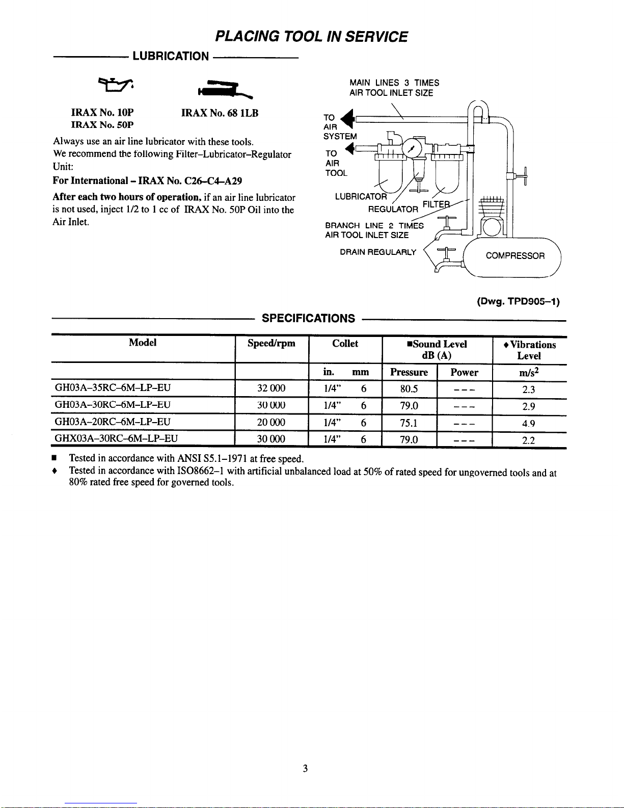
PLACING TOOL IN SERVICE
LUBRICATION
TIMES
AIR TOOL INLET SIZE
-
IRAX No. 10P
IRAX No. 50P
IRAX No. 68 1LB
Always use an air line lubricator with these tools.
We recommend the following Filter-Lubricator-Regulator
Unit:
For International - IRAX No. C26-C4-A29
After each two hours of operation, if an air line lubricator
is not used, inject l/2 to 1 cc of IRAX No. 50P Oil into the
Air Inlet.
BRANCH LINE 2 TIMES
AIR TOOL INLET SIZE
DRAIN REGULARLY
COMPRESSOR
(Dwg. TPD905-1)
SPECIFICATIONS
Model
Speed/rpm
GH03A-35RCXM-LP-EU
32 000
GH03A-30RC-6M-LP-EU
30 000
GH03A-20RC-6M-LP-EU
20000
GHX03A-30RC-6M-LP-EU
30 000
Collet
n
Sound Level Vibrations
dB (A)
Level
in. mm Pressure Power
m/S2
l/4”
6
80.5
---
2.3
l/4”
6
79.0
---
2.9
l/4”
6
75.1
---
4.9
l/4”
6
79.0
---
2.2
n
Tested in accordance with ANSI S5.1-1971 at free speed.
Tested in accordance with ISO8662-1 with artificial unbalanced load at 50% of rated speed for ungoverned tools and at
80% rated free speed for governed tools.
3

DECLARATION OF CONFORMITY
We
Ingersoll-Rand, Co.
(supplier's name)
Swan Lane, Hindley Green, Wigan WN2 4EZ
(address)
declare under our sole responsibility that the product,
Series GHO3A-EU and GHXO3A-EU Grinders
to which this declaration relates, is in compliance with the provisions of
89/392/EEC, 91/368/EEC, 93/44/EEC AND 93/68/EEC
Directives.
By using the following Principle Standards:
IS08662
Serial No. Range:
(1996 › ) XUA XXXXX ›
>>
Name and signature
of
authorised persons Name and signature
of
authorised person
June, 1996 June, 1996
Date
Date
SAVE THESE INSTRUCTIONS. DO NOT DESTROY.
When the life of the tool has expired, it is recommended that the tool be disassembled,
degreased and parts be separated by material so that they can be recycled.
4
ARO
INFORMATION GENERALE
Tool Products
6-1996
MEULEUSES DES SERIES GH03A-EU ET GHX03A-EU
Les meuleuses des Series GHOSA-EU et GHX03A-EU sont destinees aux travaux darts des endroits
restreints dans I’industrie des fabrications m&alliques, des chantiers navals, des fabrications de
tuyauteries, de matrices et de moules, et pour toutes les applications ou I’espace est limit& En particulier, elles sont ideales dans les endroits ou les tubes, tuyauteries, gaines, etc. passent 5 travers des
cloisons ou des chgssis. Ces petites meuleuses sont t&s efficaces pour le meulage des cordons de
soudure lorsqu’une bonne finition est requise.
ARO ne peut Qtre tenu re$ponsable de la modification des outils par le client pour les adapter a des
applications qui n’ont pas et6 approuvees par ARO.
tD
D’IMPORTANTES INFORMATIONS DE SECURlTi SONT JOINTES.
LIRE CE MANUEL AVANT D’UTILISER L’OUTIL.
L’EMPLOYEUR EST TENU A COMMUNIQUER LES INFORMATIONS
DE CE MANUEL AUX EMPLOY& UTILISANT CET OUTIL.
LE NON RESPECT DES AVERTISSEMENTS SUIVANTS PEUT CAUSER DES BLESSURES
MISE EN SERVICE DE L’OUTIL
UTILISATION DE L’OUTIL
Cet outil doit toujours &tre exploit& inspecte et entretenu conformement a toutes les r4glementations
(locales, departementales, fed&ales et nationales),
applicables aux outils pneumatiques tenuslcommandes a la main.
Pour la s&wit& les performances optimales et la du-
rabilite maximale des pieces, cet outil doit &-e connecti B une alimentation d’air cornprime de
6,2 bar (620 kPa) maximum B I’enttie, avec un flexible de 8 mm de diamkre int&ieur.
Couper toujours l’alimentation d’air cornprime et
debrancher le flexible d’alimentation avant d’installer, deposer ou ajuster tout accessoire sur cet outil, ou
d’entreprendre une operation d’entretien quelconque
sur I’outil.
Ne pas utiliser des flexibles ou des raccords endommages, effdoches ou dCt&iot&.
S’assurer que tous les flexibles et les raccords sont
correctement dimension&s et bien se&s. Voir Plan
TPD905-1 pour un exemple type d’agencement des
tuyauteries.
Utiliser toujours de I’air set et propre a une pression
maximum de 6,2 bar (620 kPa). La poussiere, les fumees corrosives etlou une humidit excessive peuvent
endommager le moteur d’un outil pneumatique.
Ne jamais lubrifier les outils avec des liquides intlammables ou volatiles tels que le kerosene, le gasol ou le
carburant d’aviation.
Ne Wirer aucune etiquette. Remplacer toute etiquette
endommagee.
.
Porter toujours des lunettes de protection pendant
I’utilisation et l’entretien de cet outil.
.
Porter toujours une protection acoustique pendant
l’utilisation de cet out&
.
Tenir les mains, les vi?tements flous et les cheveux
longs, eloignes de I’ext&nitC rotative de I’outil.
.
Prt%oir, et ne pas oublier, que tout outil motorise est
susceptible d’a-coups brusques lors de sa n&e en
marche et pendant son utilisation.
.
Garder une position equilibree et ferme. Ne pas se
pencher trop en avant pendant l’utilisation de cet outil. Des couples de reaction eleves peuvent se produire
a, ou en dessous, de la pression d’air recommandee.
.
La rotation des accessoires de I’outil peut continuer
pendant un certain temps apt-es le rellchement de la
glchette.
.
Les outils pneumatiques peuvent vibrer pendant I’exploitation. Les vibrations, les mouvements repetitifs et
les positions inconfortables peuvent causer des douleurs dans les mains et les bras. N’utiliser plus d’outils
en cas d’inconfort, de picotements ou de douleurs.
Consulter un medecin avant de recommencer a
utiliser 1’011th.
.
Utiliser les accessoires recommandis par ARO.
.
Cet outil n’est pas concu pour fonctionner dans des
atmospheres explosives,
.
Cet outil n’est pas isole contre les chocs electriques.
L’utilisation de rechanges autres que les pieces d’origine ARO
peut causer des risques d’insecurit4, reduire les
performances de l’outil et augmenter I’entretien, et peut annuler toutes les garanties.
Les reparations ne doivent Ctre effect&es que par des reparateurs qualifi6 autorisCs. Consultez votre Centre de Service ARO
Tool Products le plus proche.
Pour les informations relatives aux pikes et au service, contactez votre distrfbuteur ARO.
ARO Tool Products
Ingersoll-Rand Company
ARO
SWAN LANE. HINDLEY GREEN. WIGAN, UK WN2 4EZ
0942-57131
l
FAX 094265045 © WSG INGERSOLL-RAND
COMPANY
Imprime aux E.U.
Membre du groups mondial Ingersoll-Rand
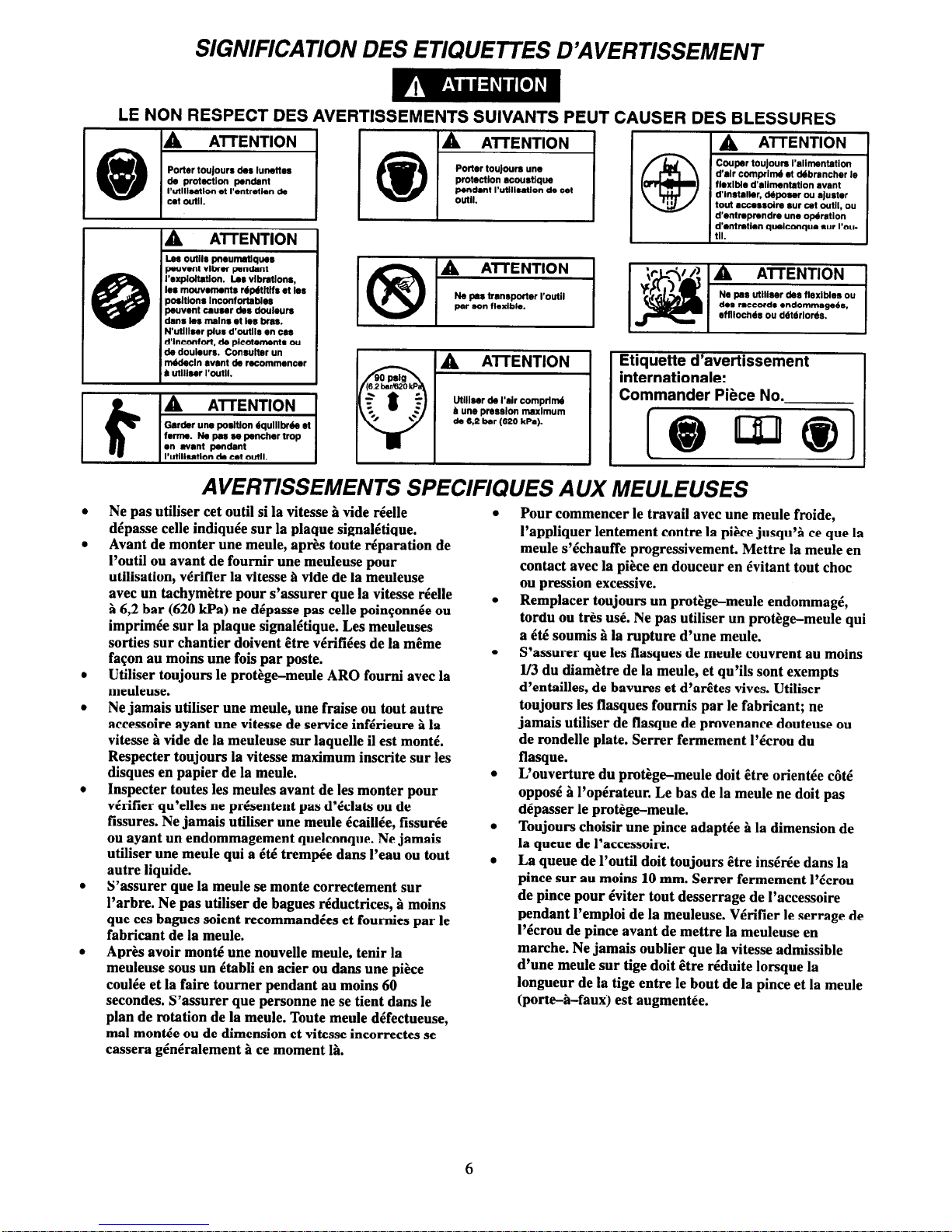
SIGNIFICATION DES ETIQUETTES D’AVERTISSEMENT
LE NON RESPECT DES AVERTISSEMENTS SUIVANTS PEUT CAUSER DES BLESSURES
Utllleer da I’alr comprlm4
B une pmsrlon maxlmum
de 6.2 bar (620 kPa).
Coupor touJoum I’allmentatlon
d’alr complti et ddbrsncher le
flexible d’rllmentatlon avant
d’lnstalkw, d4poser ou ajuster
tout acnssolm *ur cet Wtll. 0”
d’entnpmndre une opdrstlon
d’entmtlen quelconque SW I’ou-
AVERTISSEMENTS SPECIFIQUES AUX MEULEUSES
Ne pas utiliser cet outil si la vitesse g vide tielle
depasse celle indiquee sur la plaque signaletique.
Avant de monter une meule, apt% toute reparation de
I’outil ou avant de fournir une meuleuse pour
utilisation, vCrifier la vitesse B vide de la meuleuse
avec un tachymetre pour s’assurer que la vitesse tielle
S 6,2 bar (620 kPa) ne depasse pas celle poinconnee ou
imprimee sur la plaque signalktique. Les meuleuses
sorties sur chantier doivent Etre vCrifiees de la mCme
facon au moins une fois par poste.
Utiliser toujours le protege-meule ARO foumi avec la
meuleuse.
Ne jamais utiliser une meule, une fraise ou tout autre
accessoire ayant une vitesse de service inferieure B la
vitesse a vide de la meuleuse sur laquelle il est month.
Respecter toujours la vitesse maximum inscrite sur les
disques en papier de la meule.
Inspecter toutes les mettles avant de les monter pour
vdrifier qu’elles ne prkentent pas d’klats ou de
fissures. Ne jamais utiliser une mettle kaillie, fissurke
ou ayant un endommagement quelconque. Ne jamais
utiliser une mettle qui a Cti trempee dans I’eau ou tout
autre liquide.
S’assurer que la meule se monte correctement sur
l’arbre. Ne pas utiliser de bagues rkductrices, P moins
que ces bagues soient recommandees et foumies par le
fabricant de la mettle.
Apres avoir monk! une nouvelle meule, tenir la
meuleuse sous un Ctabli en acier ou dans une piece
coulee et la faire toumer pendant au moins 60
secondes. S’assurer que personne ne se tient dans le
plan de rotation de la mettle. Toute meule dGfectueuse,
ma1 montee ou de dimension et vitesse incorrectes se
cassera g&tiralement B ce moment 18.
Pour commencer le travail avec une meule froide,
I’appliquer lentement contre la piece jusqu’g ce que la
meule s’tkhauffe progressivement. Mettre la meule en
contact avec la piece en douceur en evitant tout choc
ou pression excessive.
Remplacer toujours un protege-meule endommagi,
tordu ou t&s use. Ne pas utiliser un protege-meule qui
a Cti soumis B la rupture d’une mettle.
S’assurer que les flasques de meule couvrent au moins
I/3 du diametre de la meule, et qu’ils sont exempts
d’entailles, de bavures et d’aretes vives. Utiliser
toujours les flasques foumis par le fabricant; ne
jamais utiliser de tlasque de provenance douteuse ou
de rondelle plate. Serrer fermement l’&rou du
flasque.
L’ouverture du protege-mettle doit ttre orientee c&e
opposC & l’operateur. Le bas de la mettle ne doit pas
depasser le protege-meule.
Toujours choisir une pince adaptee g la dimension de
la queue de I’accessoire.
La queue de l’outil doit toujours Ctre in&tie dans la
pince sur au moins 10 mm. Sewer fermement l’icrou
de pince pour eviter tout desserrage de I’accessoire
pendant I’emploi de la meuleuse. Verifier le serrage de
I’Ccrou de pince avant de mettre la meuleuse en
marche. Ne jamais oublier que la vitesse admissible
d’une mettle sur tige doit Ctre reduite lorsque la
longueur de la tige entre le bout de la pince et la mettle
(port&-faux) est augmentee.
6
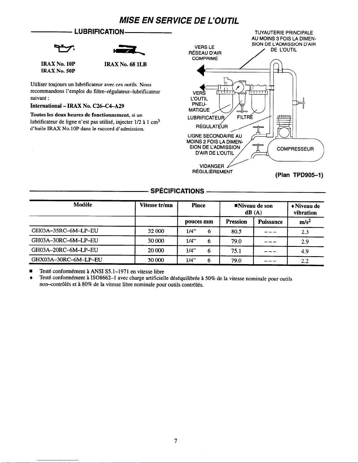
MISE EN SERVICE DE L’OUTIL
LUBRIFICATION
TUYAUTERIE PRINCIPALE
AU MOINS 3 FOIS LA DIMEN-
VERS LE
SION DE L’ADMISSION D’AIR
RiSEAU D’AIR
/ DE COUTIL
IRAX No. 10P
IRAX No. 50P
IRAX No. 68 1LB
Utiliser toujours un lubrificateur avec ces outils. Nous
recommandons I’emploi du filtre-regulateur-lubrificateur
suivant :
International - IRAX No. C26-C4-A29
Toutes les deux heures de fonctionnement, si un
lubriticateur de ligne n’est pas utilid, injecter l/2 a 1 cm3
d’huile IRAX No.10P dans le raccord d’admission.
Plan TPD905-1
SPECIFICATIONS
Modele
Vitesse tr/mn Pince
I
Niveau de son
Niveau de
!
dB (A)
vibration
pouces mm
Pression
Puissance
m/S2
GH03A-35RC-6M-LP-EU
32 000
l/4”
6
80.5
---
2.3
GH03A-30RC-6M-LP-EU
30000 1/4” 6
79.0
---
2.9
GH03A-20RC-6M-LP-EU
20000
l/4”
6
75.1
---
4.9
GHX03A-30RC-6M-LP-EU
30000 l/4” 6
79.0
---
2.2
w Teste conformement a ANSI S5.1-1971 en vitesse libre
Teste conformtment a ISO8662-1 avec charge artificielle desequilibree a 50% de la vitesse nominale pour outils
non-controlres et a 80% de la vitesse libre nominale pour outils controles.
7

CERTIFICAT DE CONFORMITE
N
OUS
Ingersoll-Rand, Co.
(nom
du
foumisseur)
Swan Lane, Hindley Green, Wigan WN2 4EZ
(adresse)
declarons sous notre seule responsabilite’ que le produit:
Meuleuses des Shies GHO3A-EU et GHXO3A-EU
objet
de ce certificat, est conforme aux prescriptions des Directives:
89/392/EEC, 91/368/EEC, 93/44/EEC, 93/68/EEC
en observant les normes de principe suivantes:
No. Serie:
(1996 -
) XUA XXXXX
-
IS08662
Nom et signature des charges de pouvoir Nom et signature des charges de pouvoir
Juin, I996
Juin, 1996
Date Date
CONSERVEZ SOIGNEUSEMENT CES INSTRUCTIONS. NE PAS LES DETRUIRE.
A la fin de sa duree de vie, il est recommande de demonter I’outil, de degraisser les pieces et de les @parer en
fonction des materiaux de maniere a ce que ces derniers puissent etre recycles.
8

ARO
BEDIENER-HANDBUCH
Tool Products
6-1996
SCHLEIFMASCHINEN DER BAUREIHE GH03A-EU UND GHX03A-EU
Schleifmaschinen der Baureihe GHOSA-EU und GHX03A-EU wurden entwickelt fur den Einsatz
in der Metallindustrie, auf Schiffswerften, bei der Rohrherstellung, Stempel- und GuRformhers-
tellung und Anwendungen auf engem Raum. Sie sind vor allem dort von Vorteil, wo Kanlle,
Rohre, Leitungen usw. unter Stiitzw8nden oder Trtigern entlangfiihren. Die kleinen Schleifmaschinen sind 8ul3erst leistungsstark beim Schleifen von SchweiBraupen und hinterlassen eine
glatte Oberfliiche.
ARO lehnt jede Haftung fur Vertinderungen an Werkzeugen ab, die ohne vorherige
Rucksprache mit ARO vorgenommen werden.
NACHFOLGEND WICHTIGE SICHERHEITSHINWEISE.
DIESES HANDBUCH VOR INBETRIEBNAHME DES WERKZEUGES UNBEDINGT LESEN.
DER ARBEITGEBER IST VERPFLICHTET, DIE IN DIESEM HANDBUCH GEGEBENEN
INFORMATIONEN DEM BEDIENER ZUGANGLICH ZU MACHEN.
DIE
NICHTEINHALTUNG DIESER WARNHINWEISE KANN ZU VERLETZUNGEN FUHREN.
INBETRIEBNAHME DES WERKZEUGES
WERKZEUGEINSATZ
Das Werkzeug stets nach den iirtlich und landesweit
geltenden Vorschriften fiir handgehalteneihandbetriebene Druckluftwerkzeuge betreiben.
Zur Erzielung hiichster Sicherheit, Leistung und
Haltbarkeit der Teile sollte dieses Werkzeug mit einem maximalen Luftdruck von 6,2 bar/620 kPa
(90 psig) am LufteinlaB und einem Luftzufuhrschlauch 8 mm Innendurchmesser betrieben werden.
Vor Montage, Demontage oder Verstellung von Aufsetzteilen bzw. Wartungsarbeiten dieses Werkzeugs
die Druckluftversorgung allseitig abschalten und
Druckluftschlauch abschlieBen.
Keine beschiidigten, durchgescheuerten oder abgenutzten Luftschliiuche und Anschltisse verwenden.
Darauf achten, da8 alle SchlHuche und Anschliisse die
passende GriiBe haben und korrekt befestigt sind. In
Zeichnung TPD905-1 ist eine typische Rohrleitungsanordnung abgebildet.
Stets saubere, trockene Luft verwenden und einen
Luftdruck von 6,2 bar/620 kPa verwenden. Staub,
iitzende Dimpfe undloder Feuchtigkeit kiinnen den
Motor eines Druckluftwerkzeuges beschidigen.
Die Werkzeuge nicht mit brennbaren oder fliichtigen
Fltissigkeiten wle Kerosin und Diesel schmieren.
Keine Aulkleber entfemen. Beschiidigte Autkleberaustauschen.
.
.
.
.
.
.
.
.
.
.
Beim Betreiben oder Warten dieses Werkzeuges stets
Augenschutz tragen.
Beim Betreiben dieses Werkzeuges stets Gehiirschutz
tragen.
Hiinde, lose Bekleidungsstiicke und lange Haare vom
rotierenden Ende des Werkzeuges fernhalten.
Bei Start und Betrieb eines Werkzeuges auf
Rtickschlag achten und darauf vorbereitet sein.
Wlhrend des Betreibens fur festen Halt sorgen und
den K&per nicht zu weit nach vorne beugen. Bei Betrieb mit empfohlenem oder niedrigerem Luftdmck
kiinnen hohe Reaktionsdrehmomente auftreten.
Nach dem Loslassen des Driickers kann das Werkzeug noch kurz weiterschlagen.
Dmckluftbetriebene Werkzeuge kiinnen wslhrend des
Betriebs vibrieren. Vibrationen, haulige gleichfiirmige
Bewegungen oder unbequeme Positionen kSnnen
schHdlich fiir Hiinde und Arme sein. Bei Unbehagen,
Krlbbeln oder Schmerzen das Werkzeug nicht mehr
bent&en. Vor dem emeuten Arbeiten mit dem Werk-
zeug iirztliche Hilfe aufsuchen.
St& von ARO empfohlenes Zubehiir
verwenden.
Das Werkzeug ist nicht ftir die Arbeit in explosiven
Atmosphffren geeignet.
Dieses Werkzeug ist nicht gegen elektrischen Schlag
isoliert.
Die Verwendung von nicht Original-ARO Ersatzteilen kann Sicherheitsrisiken, verringerte Standzeit und erhohten
Wartungsbedarf nach sich ziehen und alle Garantieleistungen ungiiltig machen.
Reparaturen sollen nur von geschultem Personal durchgefiihrt werden. Wenden Sie sich an Ihre niichste ARO Tool Proucts
Niederlassung oder den autorisierten Fachhandel.
Fur informationen zu Teilen und Dienstleistungen wenden Sie sich bitte an die ARO-Vertretung in lhrer Nahe.
ARO Tool Products
Ingersoll-Rand Company
ARO
SWAN LANE • HINDLEY GREEN • WIGAN, UK WN2 4EZ
0942-57131
l
FAX 0942-55045
©
1996 INGERSOLL-RAND CoMPANY
Gedruckt in den U.S.A.

ANWEISUNGEN AUF WARNSCHILDERN
DIE NICHTEINHALTUNG DIESER WARNHINWEISE KANN ZU VERLETZUNGEN FUHREN.
Druckltibetrlabene Warkzauge
k&hen w6hrend da8 Setrleba
vlbrleren. Vlbratlormn, hlluflge
gleichf6rmlge Bmegungan ode1
unbequem Poaltlonen k&man
achlidllch liir H6nda und Amm
6411. BeI Unbahagen, Krlbbeln
oder Schmemn das Werkzeug
nlcht mshr benutzen. Vor dam
ameuten Arbalten mlt dem
Werkzeug 6tztllcha Hllfa aufsuehan.
Mlt elnem maximalan
Luttdruck van 6,2 bar/620
kPa (90 pslg) batralban.
SCHLEIFMASCHINEN-SPEZIFISCHE WARNHIN WEISE
Das Werkzeug nicht einsekeq wenn die tat&hliche freie
Dmhzahl die auf dem Typenschild angegebene Drehzahl
iibers&reitet.
Vor dem Auf&ken einer Schleifscheibe, nach jeder
Werkzeugteparatur oder vor dem Ersteinsak einer
Scblei~ ist St& nit einem Tachometer &her zu
stellen, daU die taticldiche freie Dtehzahl der
Schleifmaschine bei 6,2 bar/620 kPa (90 psig) die auf dem
‘Qpenschild eingestempelte oder gedntckte Drehzahl
nicht iiberschreitet. Ebenso m&en im Einsak befindliche
Schleihnaxhmen mindestens einmal pro Schicht
iiberpriilk werden
Stets die empfohlene, mit der Schleifmaschine gelieferte
ARO SchleiBcheibe~ukvorrichtung verwenden.
Niemals eine SchleiBcheibe, ehren Grat oder sonstiges
Zubehiir verwenden, dessert
H&hstbetriebsgeschwindigkeit geringer als die freie
Drehzahl der eingesekten Schleifma&ine ist. Stets die
Hiichstdrphzahl des Schleifscheibenpapieres beachter~
Vor dem At&ken alle Schleifscheiben auf L&her und
Rise ilberprilfen Keine Schleifscheiben verwenden, die
L&her, R&e oder sonstige Sch%den aufweisen. Keine
Schlei&cheiben verwenden, die tiber bingere Zeit mit
Wasser oder einer anderen Fliissigkeit in Kontakt waren
Datauf achten, daB die Schleifscheibe tichtig auf der
Spindel sikt. Keine Reduzierhiilsen verwenden, um ehte
Schleifkheibe an eine Spindel anzupaasen, es sei denn,
eine entsprechende Htilse wurde vom Scheibenhersteller
mitgeliefert und empfohlen.
Nach bem Aufsetzen einer neuen Schleifscheibe die
Scfdeifma&me unter einer Stahlwerkbank oder hinter
einem Metallschuk mindestens 60 Sekunden lang
laufenlassen Darauf achten, dalI sich niemand in
Reichweite der Schleifmaechine authiilt. Ist eine
Schleifscheibe defekt, un.sachgemiiR aufgesekt oder hat
die falsche Gtige und Drehmhl, wird sich dies hier
gewiklich herausstellen
Beim Starten mit einer kalten Schleifscheibc ist diese
vorsichtig an das Werkstiick hemmufiihren, bis sie sich
auf Betriebstemperatur erw&mt hat. Der Kontakt mit
dem Werkstiick sollte glatt und ohne Stogbewegungen
oder zu hohen Druck erfolgen
Bexhiidigte, verbogene oder stark verschlissene
Schleifscheibenschukvorrichtungen stets auswechseln.
Keine Schleifscheibenschukvorrichumgen verwenden,
unter deren Einsak em Schlei&cheibenausfall a&rat.
Darauf achteq daB die Schleikcheibenflansche
mindestens ein Drittel des Durchmessers der
Schleibxheibe haben und keine Kerben, Grate oder
scharfen Kanten aufweisen Stets die empfohlene, mit der
Schleilinaschine gelieferte Ingersoll-Rand
SchleiBcheibenBansche verwenden Keinen pt&sorischen
Flansch oder eine blanke Scheibe verwenden Die
Fhmschmutter feskiehen
Die &fmmg der Schukvorrichtung mug vom Bediener
abgewandt sein Der untere Rand der Schleifscheibe darf
nicht iiber die Schukvorrichtung hinausragen.
Die Spannfuttergriige muI3 stets mit der SchaftgriiBe
des Werkzeugvorsakes tibereinstimmen.
Den Schaft des Werkzeugvorsakes mindestens 10 mm
in das Spannfutter einftihren. Die Spannmutter
feskiehen, so dag sich der Werkzeugvorsak wahrend
des Betriebs der Schleifmaschine nicht Risen kann.
Vor dem Betreiben der Schleifmaschine die Festigkeit
der Spannmutter tiberpriifen. Es ist zu beachten, dag
sich die zullissige Drehzahl eines Werkzeugvorsatzes
mit zunehmender Schafthinge zwischen
Spannfutterende und Werkzeugvorsak verringert
(Ausladung).
10

INBETRIEBNAHME DES WERKZEUGES
SCHMIERUNG
IRAX Nr. 10P
IRAX Nr. 50P
IRAX Nr. 68 1LB
Das Werkzeug stets mit einem Leitungsijler verwenden.
Es wird folgende Filter-Regleraler-Kombination
empfohlen:
IRAX Modell-Nr. C26-C4-A29
Wird kein Leitungsoler verwendet, nach jeweils zwei
Betriebsstunden 0,5 - 1 ccm IRAX-Ol Nr. 10P in den
LufteinlaB des Werkzeuges geben.
ZUM HAUPTROHRLEITUNG MIT DREIFACHEM
DRUCKLUFT- DURCHMESSER DES
DRUCKLUFT-
WERKZEUG
NEBENROHRLEITUNG
MIT ZWEIFACHEM
DURCHMESSER DES
LUFTEINLASSES
ABLASSEN
KOMPRESSOR
I
(Zeichn. TPD905-1)
TECHNISCHE DATEN
Modell
Drehzahl/
U/Min
Spannfutter Schallpegel
dB (A)
Schwin-
gungs-
intensitat
GH03A-35RC-6M-LP-EU
GH03A-30RC-6M-LP-EU
GH03A-20RC4M-LP-EU
GHX03A-30RC-6M-LP-EU
32000
30 000
20000
30 000
in. mm Druck Leistung m/s2
l/4”
6
80.5
---
2.3
l/4”
6
79.0
---
2.9
l/4”
6
75.1
---
4.9
1/4”
6
79.0
---
2.2
n
Gems8 ANSI S5. l-l 971 bei freier Drehzahl getestet
+
GemPB ISO8662-1 mit einer kiinstlichen, unsymmertischen Belastung bei 50% der Nenndrehzahl fur ungeregelte
Werkzeuge und 80% der freien Nenndrehzahl fur geregelte Werkzeuge getestet.
11

KONFORMITATSERKLARUNG
Wir
Ingersoll-Rand, Co.
(Name des Herstellers)
Swan Lane, Hindley Green, Wigan WN2 4EZ
(Adresse)
erklaren hiermit, gemas unserer alleinigen Verantwortung, das die Gerate:
Schleijkaschinen der Baureihe GHO3A-EU und GHXO3A-EU
auf die sich diese Erklarung bezieht, den Richtlinien:
89/392/EEC, 91/368/EEC, 93/44/EEC, 93/68/EEC
unter Anlehnung an die folgenden Grundnormen
entsprechen:
IS08662
Serien-Nr.-Bereich:
(1996 - ) XUA XXXXX -
Juni, 1996 Juni, 1996
Datum Date
DIESE ANWEISUNGEN SIND SORGFALTIG AUFZUBEWAHREN. NICHT ZERSTOREN.
Zur Entsorgung ist das Werkzeug vollstandig zu demontieren, zu entfetten und nach Materialarten
getrennt der Wiederverwertung zuzufuhren.
12

ARO MANUALE DELL’OPERATORE
6-1996
Tool Products
0
I
SMERIGLIATRICI SERIE GH03A-EU E GHX03A-EU
Le smerigliatrici delle serie GH03A-EU e GHXOSA-EU sono state progettate per il lavoro in
ambienti ristretti nell’industria metallurgica, nei cantieri navali, nelle aziende produttrici di tubi, di stampi
e nelle applicazioni in cui lo spazio i% limitato. Sono particolarmente efficienti nei casi di condotte, tubazioni e condutture passanti attraverso paratie o telai. Queste piccole smerigliatrici sono molto eff icienti
nell’asportare bave di saldatura e produrre una rifinitura di elevata qualita.
La ARO non B responsabile delle modifiche apportate agli attreui dai clienti per adattarli ad
applicazioni per le quali la ARO non sia stata interpellata.
IMPORTANTE INFORMAZIONE DI SICUREZZA ACCLUSA.
i:
LEGGERE IL PRESENTE MANUALE PRIMA DI USARE L’AlTREZZO.
RESPONSABILITA DEL DATORE DI LAVORO DI MElTERE QUEST’INFORMAZIONE
NELLE MANI DELL’OPERATORE.
LA MANCATA OSSERVANZA DELLE SEGUENTI AVVERTENZE Pub CAUSARE
LESIONI FISICHE
MESSA IN SERVIZIO DELL’ATTREZZO
COME USARE L’AlTREZZO
.
Usare, ispezionare e mantenere sempre quest’attrezzo
second0 tutti i regolamenti (locali, statali, federali e
nazionali), the possano essere applicahili agli attrezzi
a mano pneumatici.
.
Per sicurezza, massime prestazioni e massima durabiliti delle parti, usare quest’attrezzo ad una massima
pressione d’aria di 90 psig (6,2 bar/620 kPa) all’ingresso con un flessibile di alimentazione dell’aria con
diametro interno di 5/16” (8 mm).
.
Disinserire sempre l’alimentazione aria e staccare il
relativo tubo dall’attrezzo, prima di installare, togliere
0 regolare qualsiasi accessorio, oppure prima di eseguire qualsiasi operazione di manutenzione dell’attrezzo.
l
Non adoperare tubi e raccordi danneggiati, consunti o
deteriorati.
.
Assicurarsi the tutti i tubi ed i raccordi siano delle
corrette dimensioni e saldamente serrati. Consultare
il disegno TPD905-1 per una tipica disposizione dei
tubi.
.
Usare sempre aria pulita ed asciutta alla pressione
max di 90 psig(6,2 bar/620 kPa). Polvere, fuml corrosivi e/o un eccesso di umiditi possono rovinare il motore di un attrezzo pneumatico.
l Non lubrificare gli utensili con liquidi infiammabili o
volatili come kerosene, gasolio o combustibile per
aviogetti.
.
Non togliere nessuna etichetta. Sostituire eventuali
etichette danneggiate.
.
Indossare sempre degli occhiali protettivi quando si
adopera questo attrezzo o se ne esegue la manutenzione.
.
Indossare sempre delle cuffte protettive quando si
adopera questo attrezzo.
.
Tenere le mani, gli indumenti sciolti ed i capelli lunghi
distanti dall’estremitji battente dell’attrezzo.
.
Fare attenzione e cercare di anticipare improvvise
variazioni di movimento durante l’awiamento e l’uso
di qualsiasi utensile pneumatico.
.
Nell’usare I’attrezzo, mantenere con il corpo una posizione salda e ben bilanciata. Non sbilanciarsi durante
I’uso di questo attrezzo. Delle elevate reazioni di coppia si possono vericare alla pressione d’aria raccomandata o inferiore.
.
L’accessorio dell’utensile potrebbe continuare a funzionare brevemente dopo che e stata disinserita l’immissione.
l Gli attrezzi pneumatici possono vibrare durante I’uso.
Le vibrazioni, i movimenti ripetitivi o le posizioni sco-
mode possono risultare dannosi per le mani e le braccia. Interrompere l’uso dell’utensile se si awertono
sintomi di disagio fisico, formicolio o dolore. Interpellare un medico prima di riprendere il lavoro.
.
Usare accessori raccomandati dalla ARO.
l Questo utensile non e stato progettato per operate in
atmosfere esplosive.
l Quest0 utensile non e isolato contra le scosse elet-
triche.
L’uso di ricambi non originali ARO potrebbe causare condizioni di pericolositi, compromettere le prestazioni
dell’attrezzo ed aumentare la necessiti di manutenzione, inoltre potrebbe invalidare tutte le garanzie.
Le riparazioni devono essere effettuate soltanto da personale autorizzato e qualificato. Rivolgersi al pill vicino centro di
assistenza tecnica ARO Tool Products.
Per informazioni sulle parti di ricambio ed assistenza, contattare il distributore ARO.
ARO Tool Products
Ingersoll-Rand Company
ARO
SWAN LANE. HINDLEY GREEN. WIGAN, UK WN2 4EZ
094257131
l
FAX 0942-55045 ©
1996 INGERSOLL-RAND COMPANY
Stampato in U.S.A.
Parte della Ingersoll-Rand Mondiale

LA MANCATA OSSERVANZ
,
IDENTIFICAZIONE DELLE ETICHETTE Dl AVVERTENZA
CAUSARE LESIONI FISICHE
Indossare sempm dogIl
occhlall protefflvl quando sl
adopsm quest0 attmuo 0 M
no eseglle Ia “la”ute”7.ione.
adopera quest0
~ttmzzo.
relstlvo tuba. prima dl installam.
AVVERTENZA
GII attnzzl pnewnatlcl possono
vlbmre dumts I’UIO. Le
vlbmzloni, I movlmentl rlpetltlvl
0 IO poslzlonl sco”lode possono
rlrultare dannorl per IO numl a le
bmccla Interrompers l’uso
dell’ut.“rlle se ai avvertono
sintoml dl dirrglo fisico,
fo”~‘~lcollo o dolore. Intrrpellsre
“n rnedlco prkna dl ripmndere II
lavofo.
Lavorare con masslma
pmrrlone aria dl 90 psig
(6.2 bar/620 kPa).
J
AVVERTENZE SPECIFICHE PER LE SMERIGLIATICI
Non utilizzare quest0 attrezzo se la velocit4 libera
effettiva supera il valore indicate sulla targhetta dei dati.
Prima di montare una mola, dopo una qualsiasi
riparazione dell’attrezzo, oppure ogni qualvolta una
smerigliatrice viene consegnata all’operatore per l’uso,
controllare con un contagiri la velociti libera della
smergliatrice onde accetarsi the la sua velociti effettiva
alla pressione di 90 psig (6,2 bar/620kPa) non supera il
valore in glrilmin. Le smerigliatrici in uso sul luogo di
lavoro devono essere sottoposto a un controllo analog0
almeno ad ogni turn di lavoro.
Usare sempre la cuffia di protezione ARO consigliata e
fornita insieme alla smerlgliatrice.
Non adoperare alcuna mola, fresa o altro accessorio
avente una velocitii operativa massima inferiore alla
velociti libera della smerigliatrice su cui tale accessorio
deve essere montato. Attenersi sempre alla massima
velocita indicata sull’etichetta delle mole.
Controllare the tutte le mole non presentono
scheggiature o incrinature prima di montarle
sull’attrezzo. Non utilizzare una mola scheggiata,
incrinata o altrimenti danneggiata. Non adoperare una
mola scheggiata, incrinata o altrimenti danneggiata. Non
utilizzare una mola the sia stata tenuta a bagno
nell’acqua o in altro liquido.
Assicurarsi the la mola calza correttamente sull’albero.
Non utilizzare delle boccole di riduzione per adattare una
mola ad un albero, a meno the tali boccole non siano
state fornite e consigliate dal fahbricante della mola.
Dopo aver montato una nuova mola, posizionare la
smerigliatrice sotto un banco di lavoro in acciaio, o
all’interno di un pezzo fuzo ed azionarla per almeno 60
secondi. Assicurarsi the nessuno si trova nel piano
operativo della smerigliatrice. Se una mola disco e
difettosa, montata erroneamente o della dimensione o
velociti sbagliata, essa, generalmente, si rompera
durante quest0 collaudo.
Quando si inizia a lavorare con una mola fredda
applicarla alla superticie di lavoro lentamente, finch6 non
si riscalda gradualmente. Portare la mola a contatto con
la superllcie di lavoro un maniera progressiva, evitando
gli urti e la pressione eccessiva.
Sostituire sempre una cuffta di protezione danneggiata,
piegata o gravemente usurata. Non utilizzare una cuflla
di protezione the sia stata soggeta ad una rottura della
mola.
Assicurarsi the le flange della mola siano pari ad almeno
1/3 del diametro della mola. Usare sempre le flange della
mola fornita dal fabbricante; noon adoperare mai una
flangia improvvisata, oppure una rondella liscia. Serrare
saldamente il dado della fangia.
L’apertura della cuffia di protezione deve essere rivolta
in direzione opposta all’operatore. La parte inferiore
della mola non deve sporgere oltre la cuflla di protezione.
Assicurarsi sempre the la dimensione della pinza
corrisponda a quella del gamho dell’accessorio.
Inserire sempre il gambo dell’attrezzo nella pinza in
mlsura non inferiore a 10 mm. Serrare accuratamente il
dado della pinza, onde impedire la fuoriuscita
dell’accessorio durante l’azionamento della
smerlgliatrice. Controllare il serraggio de1 dado della
pinza prima di azionare la smergliatricie. Prestare
particolare attenzione al fatto the la velociti consentita di
una mola a gambo viene diminuita quando la lunghezza
dell’albero tra l’estremita della pinza e la mola viene
incrementata (sporgenza).
14

MESSA IN SERVIZIO DELL’ATTREZZO
LUBRIFICAZIONE
IRAX Nr. 10P
IRAX Nr. 50P
IRAX Nr. 68 1LB
Con questi attrezzi usare sempre un lubrificatore di linea.
Si raccomanda l’uso de1 seguente gruppo
filtro-regolatore-lubtificatore:
per gli altri paesi -WAX Nr. C26-C4-A29
Dopo ogni due ore di fuuzionamento, se non viene usato un
lubrificatore di linea, iniettare da 112 a 1 cc di olio IRAX
Nr. IOP nell’entrata aria.
TUBAZIONE
PRINCIPALE, 3 VOLTE
LA DIMENSIONE
ALCIMPIANTO
DELCENTRATA ARIA
PNEUMATIC0
DELCUTENSILE
ALL’
PNE
LA DIMENSIONE COMPRESSORE
DELCENTRATA ARIA
DELCUTENSILE
SVUOTARE
REGOLARMENTE
(il disegno TPD905-1)
SPECIFICA
Modello
Velociai,
Anello metallico
Livello suono
Livello di
giri/min
dB (A)
vibrazione
poll. mm Pressione
Potenza
m/s2
GH03A-35RC-6M-LP-EU
32 000 l/4” 6
80.5 ---
2.3
GH03A-30RC-6M-LP-EU
30000 l/4” 6
79.0 ---
2.9
GH03A-20RC-6M-LP-EU
20000
l/4” 6 75.1 ---
4.9
GHX03A-30RC-6M-LP-EU
30000 l/4” 6
79.0 ---
2.2
n
Collaudato secondo i criteri ANSI S5.1-1971 a velocith libera
+ Collaudato secondo i criteri ISO8662-1 con carico artificiale non bilanciato a 50% della velocith nominale per attrezzi
non regolamentari e a velocith libera nominale de11’80% per attrezzi regolamentari.
15

DICHIARAZIONE DI CONFORMITA
Noi
Ingersoll-Rand, Co.
(nome
del
fomitore)
Swan Lane, Hindley Green, Wigan WN2 4EZ
(indirizzo)
dichiariamo sotto la nostra unica responsabilita che il prodotto:
Smerigliatrci Serie GHO3A-EU e GHXO3A-EU
a cui si riferisce la presente dichiarazione e conforme alle normative delle direttive:
89/392/EEC, 91/368/EEC, 93/44/EEC, 93/68/EEC
secondo i seguenti standard:
IS08662
Numeri di Serie:
(1996 - ) XUA XXXXX -
Giugno, 1996
Giugno, 1996
Data
Data
CONSERVARE QUESTE INSTRUZIONI. NON DISTRUGGERLE.
Quando l’attrezzo diventato inutilizzabile, si raccomanda di smontarlo, sgrassarlo e separare i componenti secondo i
materiali in modo da poterii riciclare.
16

GUiA DEL OPERARIO
6-1996
Tool Products
0
E
AMOLADORAS MODELOS GH03A-EU Y GHX03A-EU
Las Amoladoras Serie GH03A-EU y GHXOBA-EU estan disefiadas para trabajo de cercania en la industria
de fabricacidn de metales, astilleros, fabrication de tuberias, fabrication de moldes y troqueles y aplica-
ciones en espacios reducidos. Resultan especialmente eficaces para aquellas situaciones en las que 10s
conductos, tuberias, etc. atraviesan tabiques o bastidores. Estas pequeiias amoladoras son muy eficaces para rectificar cordones de soldadura y dejar un acabado fino.
ARO no aceptara responsabilidad alguna por la modification de las herramientas efectuada por el
cliente para las aplicaciones que no hayan sido consultadas con ARO.
w
SE ADJUNTA INFORMACl6N IMPORTANTE DE SEGURIDAD.
LEA ESTE MANUAL ANTES DE USAR LA HERRAMIENTA.
ES RESPsONSABILIDAD DE LA EMPRESA ASEGURARSE DE QUE EL OPERARIO
ESTE AL TANTO DE LA INFORMACldN WE CONTIENE ESTE MANUAL.
EL HACER CASO OMISO DE LOS AVISOS SIGUIENTES PODRiA OCASIONAR LESIONES.
PARA PONER LA HERRAMIENTA EN
SERVICIO
US0 DE LA HERRAMIENTA
.
.
.
.
.
.
.
.
.
.
Use siempre protecci6n ocular cuando maneje, o realice operaciones de mantenimiento en esta herramienta.
Use, inspeccione y mantenga esta berramienta
siempre de acuerdo con todas las normativas (locales,
e&tales, federales, nacionales), que apliquen a las
berramientas neumaticas de operacidn y agarre
manual.
Para seguridad, maxim0 rendimiento y vida de servicio de las piezas, use esta berramienta a una presi6n
de aire maxima de 90 psig (6,2 bar/620 kPa) en la
admisi6n de manguera de suministro de aire con
diametro intemo de 8 mm.
Corte siempre el suministro de aire y desconecte la
manguera de suministro de aire antes de in&alar, desmontar o ajustar cualquier accesorio de esta berramienta, o antes de realizar cualquier opera&&t de
mantenimiento de la misma.
No utilice mangueras de aire y accesorios daiiados,
desgastados ni deteriorados.
Asegirrese de que todas las mangueras y accesorios
Sean de1 tamatio con-e& y es&t bien apretados. Vea
Esq. TPD905-1 para un tfpico arreglo de tuberias.
Use siempre aire limpio y seco a una presi6n maxima
de 90 bar (6,2 bar/620 kPa). El polvo, 10s gases corrosivos y/o el exceso de humedad podrian estropear el
motor de una herramienta neumatica.
No lubrique las herramientas con lfquidos inflamables
o volatiles tales coma queroseno, gasoil o combustible
para motores a reacci6n.
No saque ninguna etiqueta. Sustituya toda etiqueta
daiiada.
Use siempre protecci6n para 10s oidos cuando maneje
esta herramienta.
Mantenga las manos, la ropa suelta y el cabello largo
alejados de1 extremo giratorio de la herramienta.
Anticipe y est4 alerta sobre 10s cambios repentinos en
el movimiento durante la puesta en marcha y el manejo de toda herramienta motorizada.
Mantenga una postura de cuerpo equilibrada y firme.
No estire demasiado 10s brazos al manejar la herramienta. Pueden ocurrir reacciones de alto par a, o a
menos de, la recomendada presi6n de aire.
Los accesorios de la herramienta podrfan seguir girando brevemente despues de haber soltado la palanca de estrangulaci6n.
Las herramientas neumaiticas pueden vibrar durante
el uso. La vibrac%n, repetition o posiciones in&modas pueden daiiarle 10s brazos y manos. En case de
incomodidad, sensacidn de hormigueo o dolor, deje de
usar la herramienta. Consulte a un medico antes de
volver a usarla otra vez.
Utilice linicamente 10s accesorios ARO recomendados.
Esta herramienta no ha sido diseiiada para trabajar
en ambientes explosivos.
Esta herramienta no esta aislada contra descargas
electricas.
ARO Tool Products
Ingersoll-Rand Company
SWAN LANE. HINDLEY GREEN. WIGAN, UK WN2 4EZ
0942-57131
l
FAX 0942-55045 © 1999
INGERsoLL-RAND COMPANY
lmpreso en EE.UU.
Parte del grupo mundial Ingersoll-Rand
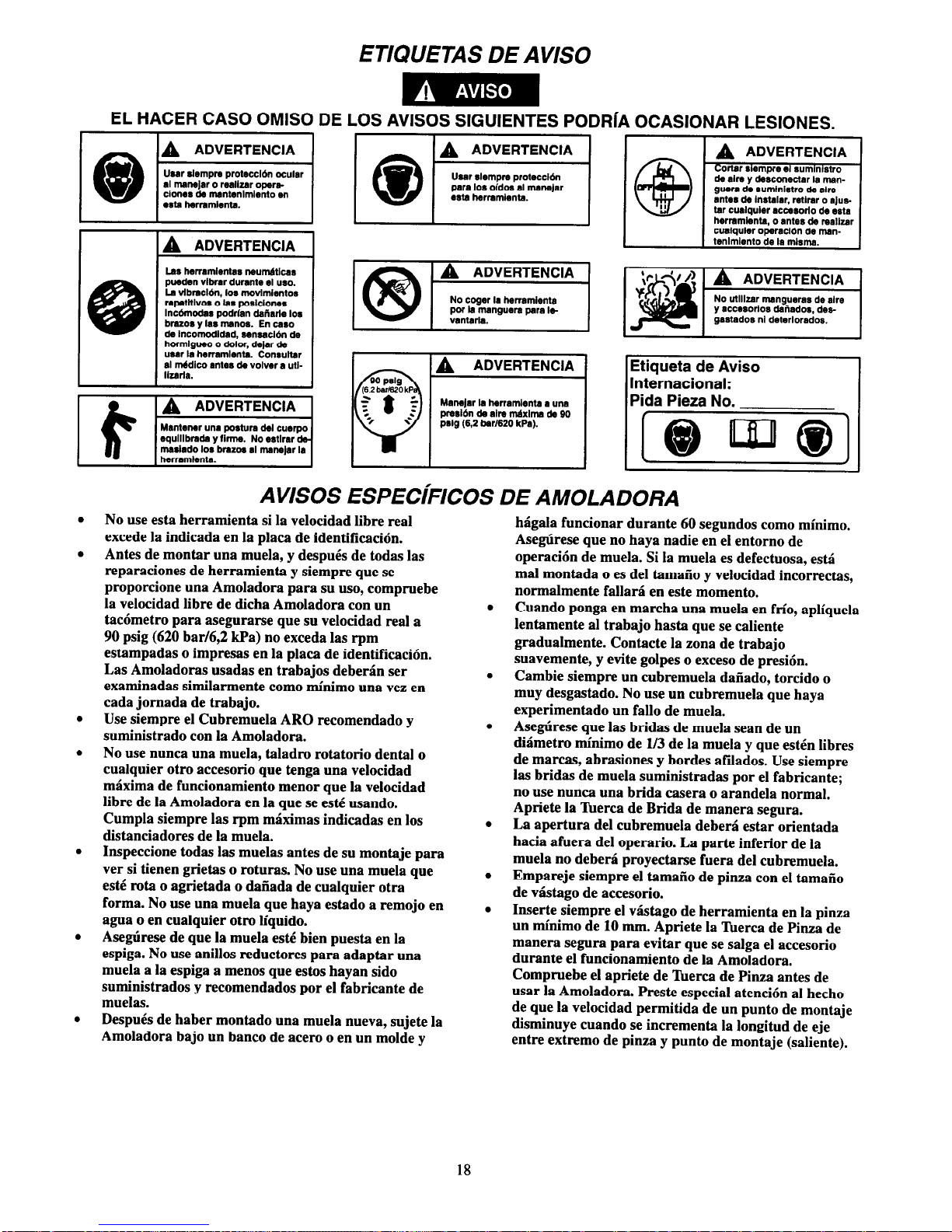
ETIQUETAS DE AVIS0
EL HACER CASO OMISO DE LOS AVISOS SIGUIENTES PODRIA OCASIONAR LESIONES.
pnrldn da alm m6xlma da 90
Pslg (6.2 bar1620 kPa).
gwra de sumlnlstro de alre
ant*8 de Instalar. retlrar 0 ajus.
tar cualquler acmsorlo de esta
hermmlanta, o antes de raallzar
cualquler operacl6n de msn-
Etiqueta de Avis0
International:
Pida Pieza No.
AVISOS ESPECIFICOS DE AMOLADORA
No use esta herramienta si la velocidad libre real
excede la indicada en la placa de identificaci6n.
Antes de montar una muela, y despues de todas las
reparaciones de herramienta y siempre que se
proporcione una Amoladora para su uso, compruebe
la velocidad libre de dicha Amoladora con un
tac6metro para asegurarse que su velocidad real a
90 psig (620 bar/6,2 kPa) no exceda las rpm
estampadas o impresas en la placa de identificaci6n.
Las Amoladoras usadas en trabajos deberan ser
examinadas similarmente coma minima una vez en
cada jomada de trabajo.
Use siempre el Cubremuela ARO recomendado y
suministrado con la Amoladora.
No use nunca una muela, taladro rotatorio dental o
cualquier otro accesorio que tenga una velocidad
maxima de funcionamiento menor que la velocidad
libre de la Amoladora en la que se este usando.
Cumpla siempre las t-pm maximas indicadas en 10s
distanciadores de la muela.
Inspeccione todas las muelas antes de su montaje para
ver si tienen grietas o roturas. No use una muela que
este rota o agrietada o daiiada de cualquier otra
forma. No use una muela que haya estado a remojo en
agua o en cualquier otro liquido.
Asegtkese de que la muela esti bien puesta en la
espiga. No use anillos reductores para adaptar una
muela a la espiga a menos que estos hayan sido
suministrados y recomendados por el fabricante de
muelas.
DespuCs de haber montado una muela nueva, sujete la
Amoladora bajo un banco de acero o en un molde y
hagala funcionar durante 60 segundos coma minimo.
Asegtirese que no haya nadie en el entorno de
operaci6n de muela. Si la muela es defectuosa, esk4
mal montada o es de1 tamailo y velocidad incorrectas,
normalmente fallarsi en este momento.
Cuando ponga en marcha una muela en frio, apliquela
lentamente al trabajo hasta que se caliente
gradualmente. Contacte la zona de trabajo
suavemente, y evite golpes o exceso de presi6n.
Cambie siempre un cubremuela daiiado, torcido o
muy desgastado. No use un cubremuela que haya
experimentado un fall0 de muela.
Asegtkese que las bridas de muela Sean de un
diaimetro minim0 de l/3 de la muela y que esten libres
de marcas, abrasiones y bordes afilados. Use siempre
las bridas de muela suministradas por el fabricante;
no use nunca una brida casera o arandela normal.
Apriete la Tuerca de Brida de manera segura.
La apertura de1 cubremuela debera estar orientada
hacia afuera de1 operario. La parte inferior de la
muela no debera proyectarse fuera del cubremuela.
Empareje siempre el tamaiio de pinza con el tamaiio
de v&ago de accesorio.
Inserte siempre el vhtago de herramienta en la pinza
un minima de 10 mm. Apriete la ‘Bterca de Pinza de
manera segura para evitar que se salga el accesorio
durante el funcionamiento de la Amoladora.
Compruebe el apriete de ‘kerca de Pinza antes de
usar la Amoladora. Preste especial atenci6n al hecho
de que la velocidad permitida de un punto de montaje
disminuye cuando se incrementa la longitud de eje
entre extremo de pinza y punto de montaje (saliente).
18
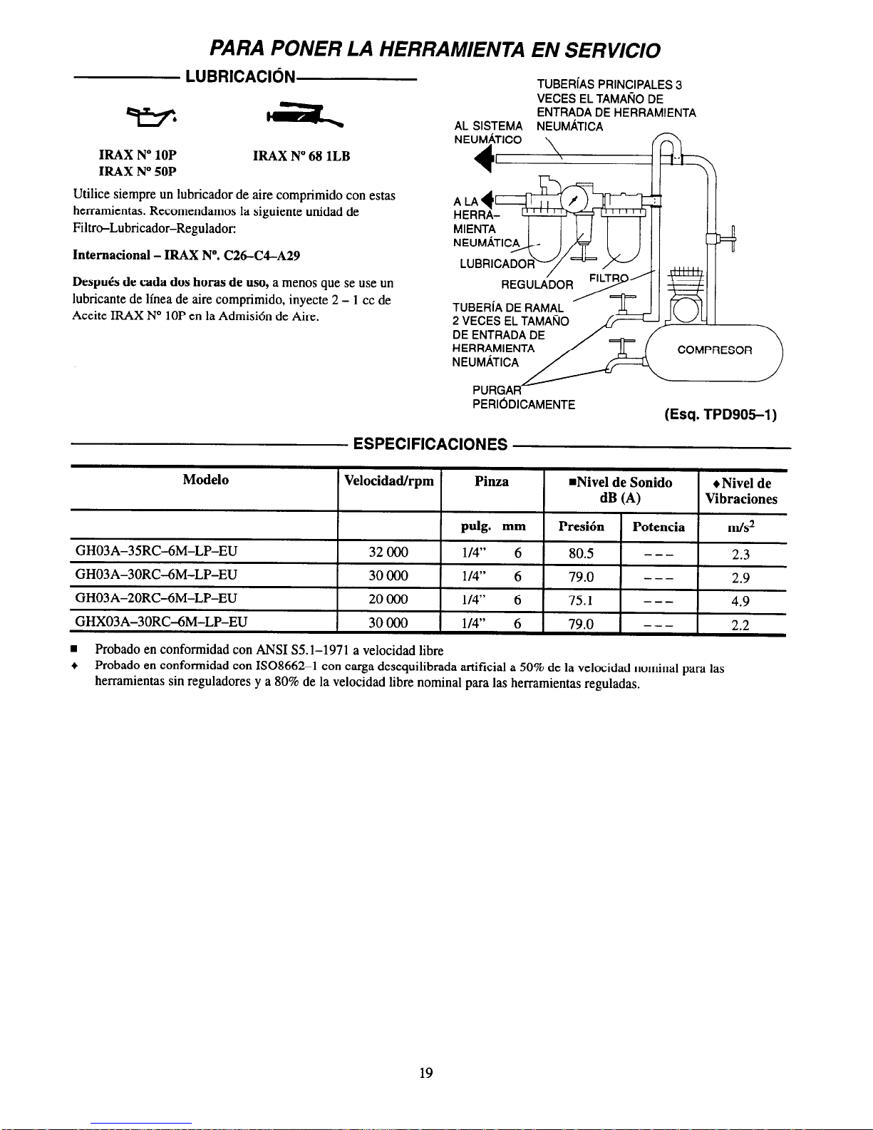
PARA PONER LA HERRAMIENTA EN SERVICIO
LUBRlCAClON
TUBERiAS PRINCIPALES 3
VECES EL TAMAfiO DE
ENTRADA DE HERRAMIENTA
AL SISTEMA NEUMATICA
IRAX N° 10P
IRAX N° 50P
IRAX N° 68 1LB
Utilice siempre un lubricador de aire comprimido con estas
herramientas. Recomendamos la siguiente unidad de
Filtro-Lubricador-Regulador:
Intemacional - IRAX N”. C2W3l-A29
Despub de cada dos horas de uso, a menos que se use un
lubricante de linea de aire comprimido, inyecte 2 - 1 cc de
Aceite IRAX N° 10P en la Admision de Aire.
TUBERiA DE RAMAL
2 VECES EL TAMARO
DE ENTRADA DE
HERRAMIENTA
COMPRESOR
PERlODlCAMENTE
(Esq. TPD905-1)
ESPECIFICACIONES
Modelo
Velocidad/rpm
Pinza
n Nivel de Sonido Nivel de
dB (A)
Vihraciones
pulg. mm
Presion
Potencia
m/s2
GH03A-35RC-6M-LP-EU 32 000
1/4” 6
80.5 ---
2.3
GH03A-30RC-6M-LP-EU 30 000
l/4” 6
79.0 ---
2.9
GH03A-20RC-6M-LP-EU 20000 l/4’* 6 75.1 ---
4.9
GHX03A-30RC-6M-LP-EU
30000 l/4” 6
79.0 --- 2.2
n
Probado en conformidad con ANSI S5.1-1971 a velocidad libre
+ Probado en conformidad con ISO8662-l con carga desequilibrada artificial a 50% de la velocidad nominal para las
herramientas sin reguladores y a 80% de la velocidad libre nominal para las herramientas reguladas.
19

DECLARACION DE COFORMIDAD
Los
abajo firmantes
Ingersoll-Rand, Co.
(nombre del proveedor)
Swan Lane, Hindley Green, Wigan WN2 4EZ
(domicilio)
Declaramos que, bajo nuestra responsabilidad exclusiva, el producto:
Amoladoras Modelos GHO3A-EU y GHXO3A-EU
a los que se refiere la presente declaracidn, cumplen con todo lo establecido en las
directivas:
89/392/EEC, 91/368/‘EEC, 93/44/EEC, 93/68/EEC
conforme a los siguientes estandares:
IS08662
Gama de No. de Serie:
(1996 - ) XUA XXXXX -
Nombre y firma de las personas autorizadas
Julio, 1996
Fecha
Julio, 1996
Fecha
GUARDE ESTAS INSTRUCCIONES. NO DESTRUYA.
Una vez vencida la vida util de herramienta, se recomienda desarmar la herramienta, desengrasarla y separar
las piezas de acuerdo con el material del que estan fabricadas para reciclarlas.
20
ARO
BEDIENINGSHANDBOEK
6-1996
Tool Products
0
NL
INSTRUCTIES VOOR
TYPEN GH03A-EU EN GHX03A-EU SLIJPMACHINES
Typen GH03A-EU en GHX03A-EU Slijpmachines zijn bedoeld voor gebruik bij werk op korte afstand in metaal
verwerkende industriebn, scheepswerven, fabricage van pijpen en buizen, matrijzen- en gietstukfabricage en
toepassingen in beperkte ruimten. Zij zijn uitermate geschikt waar leidingen, pijpen en buizen door schotten en
frames gaan. Deze kleine slijpmachines zijn uitermate efficignt bij het slijpen van lasrupsen en het verzorgen
van een perfecte afwerking.
ARO is niet aansprakelijk voor door de klant aangebrachte veranderingen aan de gereedschappen voor toepas-
singen waarover met ARO geen voorafgaand overleg werd
gepleegd.
BELANGRIJKE VEILIGHEIDSINFORMATIE IS INGESLOTEN.
EERST DIT HANDBOEK LEZEN, DAN HET GEREEDSCHAP BEDIENEN.
HET BEHOORT TOT DE VERANTWOORDELIJKHEID VAN DE WERKGEVER DE IN DIT
HANDBOEK GEGEVEN INFORMATIE AAN DE GEBRUIKER TER HAND TE STELLEN.
EEN NALATEN DE HIERNAVOLGENDE WAARSCHUWINGEN OP TE VOLGEN KAN LICHAMELIJK
LETSEL TOT GEVOLG HEBBEN.
GEBRUIK VAN HET GEREEDSCHAP
INGEBRUIKNEMING VAN HET
GEREEDSCHAP
Dit gereedschap altijd bedienen, controleren en onderhouden in overeenstemming met alle voorschriften
(plaatselijk, staat, federaal en land), die betrekking
hebben op hand-gehoudenlhand-bediende pneumatische gereedschappen.
Voor veiligheid, topprestatie, en maximale bestendigheid van de onderdelen dit gereedschap laten werken
bij een maximale luchtdruk van 90 psig
(6.2 bar/620 kPa) bij de inlaat met een luchttoevoerslang, die een inwendige diameter van 506” (8 mm)
heeft.
U moet te allen tijde oogbeschermers dragen wanneer
u dit gereedschap bedient of er onderhoudswerk-
zaamheden aan uitvoert.
Men dient te allen tijde de luchtinlaat af te sluiten en
de luchttoevoerslang te ontkoppelen voordat enig deel
aan dit gereedschap wordt aangebracht, verwijderd
of afgesteld, of voordat enig onderhoud aan dit gereedschap mag worden uitgevoerd.
Geen beschadigde, gerafelde of versleten luchtslangen
of fittingen gehruiken.
.
.
.
.
.
.
.
.
.
.
Altijd oorbeschermers dragen wanneer dit gereedschap wordt bediend.
Houd handen, losse kleding of lang haar weg van het
draaiende eind van het gereedschap.
Let op en anticipeer op plotselinge veranderingen in
de werking van enig persluchtgereedschap zowel
tijdens de start als gedurende het in bedrijf zijn.
Steeds in een goede houding staan. Als u het gereedschap hedient mag u zich niet te ver uitstrekken. Hoge
reactiekoppels kunnen voorkomen bij of beneden de
aanbevolen luchtdruk.
Zorg ervoor dat alle slangen en fittingen de juiste af-
metingen hebben en goed zijn vastgemaakt. Zie tekening TPD905-1 voor een typisch leidingnet.
Altijd schone, droge lucht gebruiken bij een maximum luchtdruk van 90 psig(6.2 bar/620 kPa). Stof,
corroderende uitwasemingen en/of te grote vochtigheid kan de motor van een drukluchtgereedschap
rumeren.
De gereedschappen niet smeren met ontvlambare of
vluchtige vloeistoffen als petroleum, diesel of (straal)
De hulpstukken van het gereedschap kan even blijven
draaien nadat de bediening is losgelaten.
Persluchtgereedschappen kunnen tijdens gebruik
ervan trillen. Trillingen, zich herhalende bewegingen,
of ongemakkelijke houdingen kunnen schadelijk zijn
voor uw handen en armen. Stop met bediening van
enig gereedschap wanneer u ongemak, een tintelend
gevoel of pijn ervaart. Zoek medisch advies alvorens
het werk te hervatten.
Uitsluitend de door ARO aanbevolen hijbehorende
hulpstukken gebruiken.
Dit gereedschap is niet ontworpen om er mee in
explosieve omgevingen te werken.
Dit gereedschap is niet geisoleerd tegen elektrische
schokken.
vliegtuigbrandstoffen. Geen typeplaatjes verwijderen. Beschadigde typeplaatjes moeten worden vervangen.
Het gebruiken van andere dan originele ARO onderdelen kan gevaar opleveren voor de veiligheid, en een vermindering met
zich brengen van het prestatievermogen van het gereedschap en een toeneming van het onderhoud ervan; het kan een vervallen
van alle garantie-bepalingen tot gevolg hebben.
Reparaties mogen uitsluitend worden uitgevoerd door hiertoe gemachtigd en geschoold personeel. Raadpleeg uw dichtstbezijnde erkende ARO Tool Products Servicenter.
ARO Tool Products
Ingersoll-Rand Company
SWAN LANE. HINDLEY GREEN. WIGAN, UK WN2 4EZ
0942-57131
l
FAX 0942-55045 © 1996 INGERSOLL-RANDCOMPANY Gedrukt in U.S.A.
Onderdeel van wereldomspannend Ingersoll-Rand
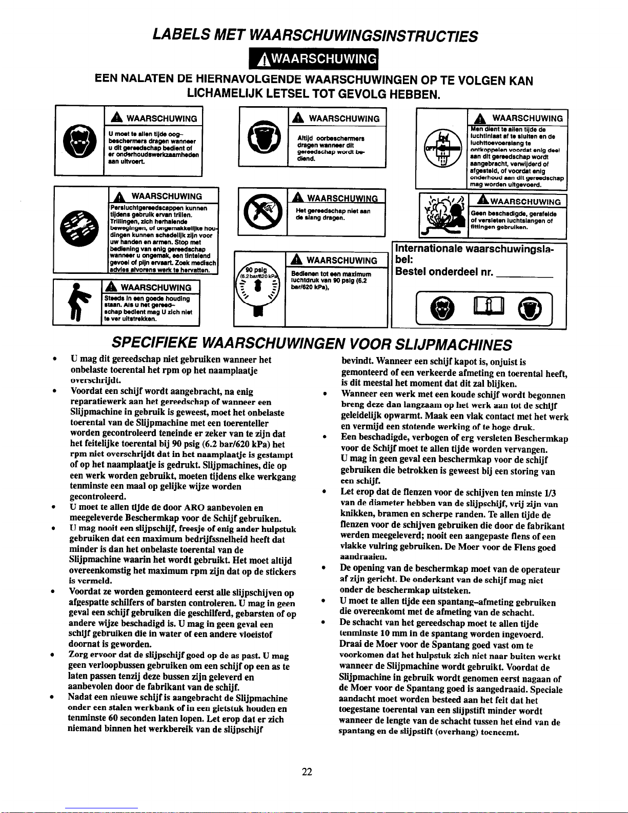
LABELS MET WAARSCHUWINGSINSTRUCTIES
EEN NALATEN DE HIERNAVOLGENDE WAARSCHUWINGEN OP TE VOLGEN KAN
LICHAMELIJK LETSEL TOT GEVOLG HEBBEN.
A
WAARSCHUWING I
IJ moat to allen UJde oogtmschernwr dragen wannc~~r
I
u dit gerwdschap bedlent of
ar ondwhoud~w6rkzaarnhed
am uitvwtt
Parsluchtgweedscap~n kunnen
tijdens gebruik enran trlllen.
TrIllIngan. rich hwhalenda
bOwegl”g~~, ot on~rnakkelljke hwdlngen kunnen schsdelljk zljn “our
uw handen en arnmn. Stop mat
bdenlng
“an l
nlg gsrwdschap
wan”.~r u ongwnak. OO” tlntelmd
gwwl ot pljn ervurt. Zwk rmdisch
advles alvorww werk to hervatten.
stwn. Als u hat gemdrchap bedlent rnag U dch nlet
to ver ultstnkkm.
I dlend.
luchtlnlaat al tb slulten en de
~~
=
ondarhoud aan dlt gerwdechq
mag worden ultgwoerd.
lnternatlonale waarschuwingslabel:
Bestel onderdeel nr.
SPECIFIEKE WAARSCHUWINGEN VOOR SLIJPMACHINES
U mag dit gereedschap niet gebruiken wanneer het
onbelaste toerental het rpm op het naamplaatje
overschrijdt.
Voordat een schijf wordt aangebracht, na enig
reparatiewerk aan het gereedschap of wanneer een
Slijpmachine in gebruik is geweest, moet het onbelaste
toerental van de Slijpmachine met een toerenteller
worden gecontroleerd teneinde er zeker van te zijn dat
het feitelijke toerental bij 90 psig (6.2 bar/620 kPa) het
rpm niet overschrijdt dat in het naamplaatje is gestampt
of op het naamplaatje is gedrukt. Slijpmachines, die op
een werk worden gebruikt, moeten tijdens elke werkgang
tenminste een maal op gelijke wijze worden
gecontroleerd.
U moet te allen tijde de door ARO aanbevolen en
meegeleverde Beschermkap voor de Schijf gebruiken.
U mag nooit een slijpschijf, freesje of enig ander hulpstuk
gebruiken dat een maximum bedrijfssnelheid heeft dat
minder is dan het onbelaste toerental van de
Slijpmachine waarin het wordt gebruikt. Het moet altijd
overeenkomstig het maximum rpm zijn dat op de stickers
is vermeld.
Voordat ze worden gemonteerd eerst alle slijpschijven op
afgespatte schilfers of barsten controleren. U mag in geen
geval een schijf gebruiken die geschilferd, gebarsten of op
andere wijze beschadigd is. U mag in geen geval een
schijf gebruiken die in water of een andere vloeistof
doornat is geworden.
Zorg ervoor dat de slijpschijf goed op de as past. U mag
geen verloopbussen gebruiken om een schijf op een as te
laten passen tenzij deze bussen zijn geleverd en
aanbevolen door de fabrikant van de schijf.
Nadat een nieuwe schijf is aangebracht de Slijpmachine
onder een stalen werkbank of in een gietstuk houden en
tenminste 60 seconden laten lopen. Let erop dat er zich
niemand binnen het werkbereik van de slijpschijf
bevindt. Wanneer een schijf kapot is, onjuist is
gemonteerd of een verkeerde afmeting en toerental heeft,
is dit meestal het moment dat dit zal blijken.
Wanneer een werk met een koude schijf wordt begonnen
breng deze dan langzaam op het werk aan tot de schijf
geleidelijk opwarmt. Maak een vlak contact met het werk
en vermijd een stotende werking of te hoge druk.
Een beschadigde, verbogen of erg versleten Beschermkap
voor de Schijf moet te allen tijde worden vervangen.
U mag in geen geval een beschermkap voor de schijf
gebruiken die betrokken is geweest bij een storing van
een schijf.
Let erop dat de flenzen voor de schijven ten minste 1/3
van de diameter hebben van de slijpschijf, vrij zijn van
knikken, bramen en scherpe randen. Te allen tijde de
flenzen voor de schijven gebruiken die door de fabrikant
werden meegeleverd; nooit een aangepaste flens of een
vlakke vuh-ing gebruiken. De Moer voor de Flens goed
aandraaien.
De opening van de beschermkap moet van de operateur
af zijn gericht. De onderkant van de schijf mag niet
onder de beschermkap uitsteken.
U moet te allen tijde een spantang-afmeting gebruiken
die overeenkomt met de afmeting van de schacht.
De schacht van het gereedschap moet te allen tijde
tenminste 10 mm in de spantang worden ingevoerd.
Draai de Moer voor de Spantang goed vast om te
voorkomen dat het hulpstuk zich niet naar buiten werkt
wanneer de Slijpmachine wordt gebruikt. Voordat de
Slijpmachine in gebruik wordt genomen eerst nagaan of
de Moer voor de Spantang goed is aangedraaid. Speciale
aandacht moet worden besteed aan het feit dat het
twgestane toerental van een slijpstift minder wordt
wanneer de lengte van de schacht tussen het eind van de
spantang en de slijpstift (overhang) toeneemt.
22
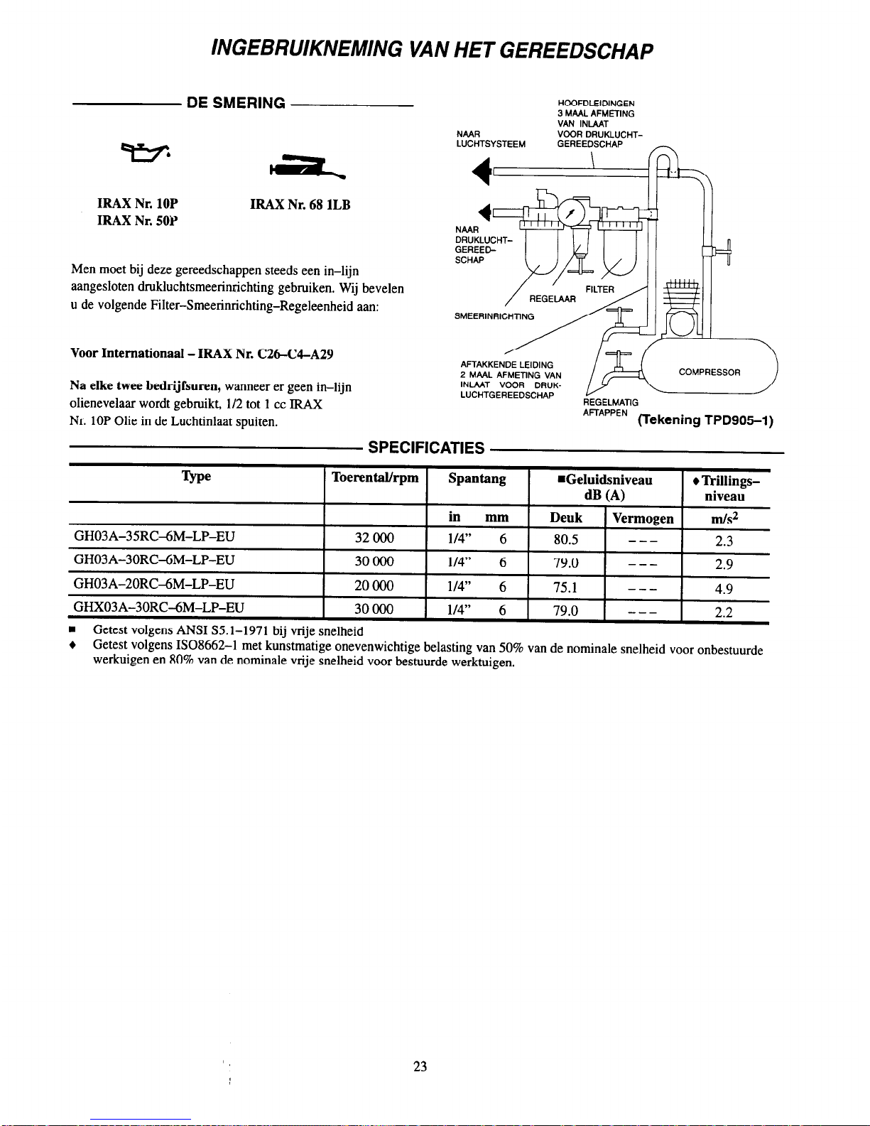
INGEBRUIKNEMING VAN HET GEREEDSCHAP
DE SMERING
IRAX Nr. 10P
IRAX Nr. 50P
IRAX Nr. 68 1LB
Men moet bij deze gereedschappen steeds een in-lijn
aangesloten drukluchtsmeerinrichting gebruiken. Wij bevelen
u de volgende Filter-Smeerinrichting-Regeleenheid aan:
Voor Intemationaal - IRAX Nr. C26-C4-A29
Na elke twee bedrijfsuren, wanneer er geen in-lijn
olienevelaar wordt gebruikt, 112 tot 1 cc IRAX
Nr. 10P Olie in de Luchtinlaat spuiten.
HOOFDLEIDINGEN
3 MAAL AFMETING
VAN INLAAT
NMR
VODR DRUKLUCHT-
LUCTM
GEREET ~~
DRUKLUCHT-
REGELMATIG
AFTAPPEN (Tekening TPD905-1)
SPECIFICATIES
Type
Toerental/rpm Spantang
n
Geluidsniveau
l
Trillings-
dB (A)
niveau
in mm
Deuk Vermogen m/s2
GH03A-35RC4M-LP-EU
32000
l/4”
6 80.5
---
2.3
GH03A-30RC-6M-LP-EU
30000
l/4"*
6
79.0
---
2.9
GH03A-20RC4M-LP-EU
20000
l/4”
6
75.1
---
4.9
GHX03A-30RC-6M-LP-EU
30000
l/4”
6
79.0
---
2.2
n
Getest volgens ANSI S5.1-1971 bij vrije snelheid
+ Getest volgens ISO8662-1 met kunstmatige onevenwichtige belasting van 50% van de nominale snelheid voor onbestuurde
werkuigen en 80% van de nominale vrije snelheid voor bestuurde werktuigen.
23

SCHRIFTELIJKE VERKLARING VAN CONFORMITEIT
Wij
Ingersoll-Rand, Co.
(naam leverancier)
Swan Lane, Hindley Green, Wigan WN2 4EZ
(adres)
verklaren, onder onze uitsluitende aansprakelijkheid, dat het produkt:
Typen GHO3A-EU en GHXO3A-EU Slijpmachines
waarop deze verklaring betrekking heeft overeenkomt met de bepalingen
van directieven:
89/392/EEC, 91/368/EEC, 93/44/EEC, 93/68/EEC
overeenkomstig de volgende hoofdstandaards:
IS08662
Serienummers:
(1996 - ) XUA XXXXX -
J. Cartwright
I
Naam en handtekening van gemachtigde personen
Juni, 1996
Juni, 1996
Datum
Datum
DEZE INSTRUCTIES GOED BEWAREN. NIET VERNIETIGEN.
Wanneer de levensduur van bet gereedschap verstreken is, wordt u aangeraden het gereedschap te demonteren en
ontvetten, en de delen gescheiden naar materialen op te bergen zodat zij gerecycled kunnen worden.
24

Ingersoll-Rand Company
510 Hester Drive
White House
TN 37188
USA
Tel: 1 800
TOOL HLP
Ingersoll-Rand
Sales Company Limited
Chorley New Road
Horwich
Bolton
Lancashire BL6 6JN
England
UK
Tel: (44) 1204 690690
Fax: (44) 1204 690388
Ingersoll-Rand
Equipements de Production
111 avenue Roger Salengro
BP 59
F - 59450 Sin Le Noble
France
Tel: (33) 27 93 0808
Fax: (33) 27 93 0800
Ingersoll-Rand GmbH
Gewerbeallee 17
45478 Mulheim/Ruhr
Deutschland
Tel: (49) 208 99940
Fax: (49) 208 9994445
Ingersoll-Rand ltaliana SpA
Casella Postale 1232
20100 Milano
ltalia
Tel: (39) 2 950561
Fax: (39) 2 95360159
Ingersoll-Rand lberica
Camino de Rejas 1, 2-18
28820 Coslada (Madrid)
Espana
Tel: (34) 1 6695850
Fax: (34) 1 6696054
Service Centers
Centres d’entretien
Niederlassungen
Centri di Assistenza
Centros de Servicio
Service Centra
Ingersoll-Rand Nederiand
Produktieweg 10
2382 PB Zoeterwoude
Nederland
Tel: (31) 71 452200
Fax: (31) 71 5218671
Ingersoll-Rand Company SA
PO Box 3720
Alrode 1451
South Africa
Tel: (27) 11 864 3930
Fax: (27) 11 864 3954
Ingersoll-Rand
Scandinavian Operations
Kastruplundgade 22, I
DK - 2770 Kastrup
Danmark
Tlf: (45) 32 526092
Fax: (45) 32 529092
Ingersoll-Rand SA
The Alpha Building
Route des Arsenaux 9
CH -1700 Fribourg
Schweiz/Suisse
Tel: (41) 37 205111
Fax: (41) 37 222932
Ingersoll-Rand Company
Kuznetsky Most 21/5
Entrance 3
103698 Moscow
Russia
CIS
Tel: (7) 501 882 0440
Fax: (7) 501 882 0441
Ingersoll-Rand Company
16 Pietro
UI Stawki 2
00193 Warsaw
Poland
Tel: (48) 2 635 7245
Fax: (48) 2 635 7332
25

NOTES
26


PN 49999-217

ARO BRUGERVEJLEDNING
6-1996
Tool Products
SLIBEMASKINER, SERIE GH03A-EU OG GHX03A-EU
Slibemaskiner af serie GHtBA-EU og GHX93A-EU er designet til brug under trange pladsforhold i metalforarbejdningsindustrien og pa skibsvaerfter, samt under fremstilling af rer og formvserktejer.
De er isazr velegnede til bearbejdning af retgennemferinger gemmen skotter og spanter.
Disse sm5 slibemaskiner er smrdeles effektive til bottslibning af svejsesem, s4 man f&r en god finish.
ARO p&ager sig intet ansvar for eventuelle aendringer af vazrktejer udfarrt af btugeren i forbindelse med anvendelsesomtider, som ARO ikke rx3 forhAnd er blevet konsulteret om.
INDEHOLDER VIGTIG SIKKERHEDSINFORMATION.
DENNE VEJLEDNING SKAL LIESES FOR BETJENING AF VIERKTOJET.
DET ER ARBEJDSGIVERENS ANSVAR AT SBRGE FOR, AT INDHOLDET
AF DENNE VEJLEDNING BRINGES TIL OPERATORENS KUNDSKAB.
MANGLENDE IAGlTAGELSE AF DISSE ADVARSLER KAN RESULTERE I PERSONSKADE.
IBRUGTAGNING AF VIERKT0JET
ANVENDELSE AF VkERKT0JET
Dette vaxkt0j skal altid betjenes, kontmlleres og vedligeholdes i overensstemmelse med de gzeldende lokale
og nationale regler for manuelle trykluftvaxk- t0jer.
Af sikkerhedshensyn og for at opt15 den bedst mulige
ydelse og levetid for vaerktajskomponenteme, skal
vaerktajet bmges ved et maksiit indgangsl~k fi
6,2
bar og med en lufttilfem4sslange, der har en ind-
vendig diameter pa 8 mm.
Der skal altid h&kc3 for hdttilf0tsleq og h&tilf0tselsslangen &al afmonterw f0r hrstallation, afmontering
eller justerhrg af tilbeh0r til dette vaerloj, e4ler f0r der
udfatw vedligeholdekesarbejde pa vaerkojet.
Der ma ikke bruges beskadigede, flossede eller nedslidte luftslanger og tilbehar.
Del skal sikm, at alle danger og alt tilbehor er af den
korrekte storrelse og er sikkert montemt. Der henvises
til tegning TPD905-1, som viser en typkk rorforing.
Der skal altid bruges ren, tar luft ved et maksiit
hdttryk pa
6,2
bar Stov, kormderende dampe og/eller
for hoj fugtighed kan odehegge motoren i et trykhtftvaerktoj.
Vaerktajer mA ikke smores med bramdbam eller flygtige wsker d som petroleum, dieselolie eller
flybrzendstof.
Maukater ma ikke fjernes. Eventuelt beskadigde
maxkater skal udskifux
.
.
.
.
.
.
.
.
.
.
Der skal altid bruges beskyttlsesbriller under betjening
eller vedligeholdelse af vaerktojet.
Der skal altid bruges hatwaem under betjening af
dette vaerktoj.
Hzender, lofstsiddende toj og langt har skal holdes borte
fra den mtetende ende af vaerktajet.
Under opstart og betjenhrg af trykhrftvaxktojer, skal
man forsage at forudse og were sgrdeles opmaxksom
over for pludselige bevazgelssesamdringen
Der skal hele tiden holdes en kropsstilling med god
balance og godt fodgreb. Som operator skal man undga
at strakke sig for langt under brug af dette vaerktoj.
Der kan forekomme voldsomme reaktionsmomenter
ved eller under det anbefalede hdttryk.
VActojsindsatsen kan fortwtte med at rotere et kort
stykke tid, efter man har sluppet hanndtaget.
Tlykhrftvzerktojer kan vibrem under brug. Vibration,
hyppigt gentague bewugelser og ubekvemme stillinger
kan vaere skadelige for operatorens hamder og arme.
Bmg af vaerktojet bar ophare, hvis man foler nogen
form for gener, en snunwrde fomemmelse i kmppen
tier
Smerter.Der
seal soges laegehjidp, far brug af
vaxktojet genoptages
Der ma kun bmges tilbehor, som anbefales af ARO.
Dette vaerktoj er ikke designet til brug i eksplosive
arbejdsmilijoer.
Dette vaerktloj er ikke isolemt mod elektriske stod.
Brug af reservedele, som ikke er originale ARO produkter, kan resultere i sikkerhedsrisici, foninget vaerktojsydelse samt ekstra
vedligehddelse, og kau gore alle garantier ugyldige.
Reparationsarbejde ma kun udfores af autoriseret og korrekt uddaunet personale.
ARO Tool servicecenter.
Kontakt venligst det naermeste autoriserede
For bestilling af dele og indhentning af yderligere oplysninger bedes De venligst kontakte Deres lokale ARO-distributor.
ARO Tool Products
Ingersoll-Rand Company
SWAN LANE. HINDLEY GREEN l WIGAN, UK WN2 4EZ
0942-57131
ARO
l
FAX 0942-55045 ©
1996 INGERSOLL-RAND COMPANY
Trykt i USA
Part of worldwide Ingersoll-Rand
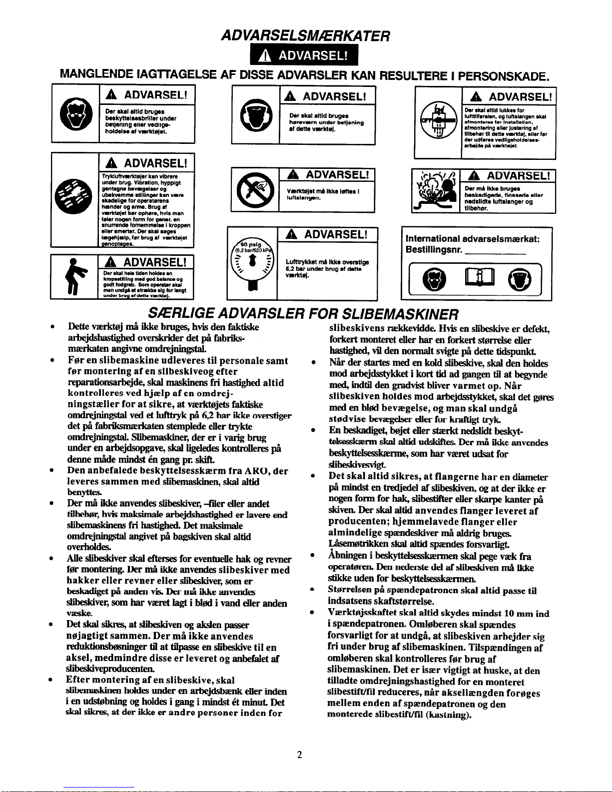
ADVARSELSM/ERKATER
MANGLENDE IAGlTAGELSE AF DISSE ADVARSLER KAN RESULTERE I PERSONSKADE.
TtWkdt’mrk?eJer km vibrere
under brug. Vibration, hyppigt
gmlugne kuagelrer og
skadrliga for opmitemnr
hmnder og arnm. Brug d
vErktojet her ophm. hvis mm
foler nogen form for Qwmr. en
legehjslp, fer brug at vaerktejet
noptages.
Lufttrykket mll ikke ovwstlge
6.2 bar under brug at dette
vmkt0j.
International advarselsmaxkat:
Bestillingsnr.
SAERLIGE ADVARSLER FOR SLIBEMASKINER
Dette vaerkoj ma ikke bruges, hvis den faktiske
arbejdshastighed ovetskrider det pa fabriksmaerkaten angivne omdrejningstal.
For en slibemaskine udleveres til personale samt
for montering af en slibeskiveog efter
reparationsarbejde, skal maskinens fri hastighed altid
kontrolleres ved hjaelp af en omdrejningstaeller for at sikre, at vauktojets faktiske
omdrejninstal ved et lufttryk pa 6,2 bar ikke overstiger
det pa fabtiksmazrkaten stemplede eller trykte
omdrejningstal. Slibermaskner, der er i varig brug
under en arbejdsopgave, skal ligekxles kontrdleres pa
denne made mindst en gang pr. skift
Den anbefalede beskyttelsesskzerm fra ARO, der
leveres sammen med slibemaskinen, skal altid
benyttes.
Der ma ikke anvendes slibeskiver, -filer eller andet
tilbehor, hvis makdmale arbejdshastighed er lavere end
slibemaskinens fri hastighed. Det maksimale
omdrcjnbqstal angivet pa bagskiven skal altid
overholdes.
Alle slibeskiver skal efterses for eventuelle hak og revner
for montering. Der ma ikke anvendes slibeskiver med
hakker eller revner eller slibeskiver, som er
beskadiget pa anden vis. Der ma ikke anvendes
slibeskiver, som har vaunt lagt i bled i vand eller anden
weske.
Det skal siknq at slibeskiven og akslen passer
nojagtigt sammen. Der mH ikke anvendes
reduktionsbominger til at tilpasse en slibeskive til en
aksel, medmindre disse er leveret og anbefalet af
slibeskivepxoducenten.
Efter montering af en slibeskive, skal
slibemaskinen hddes under en arbejdsbaenk eller inden
i en udstobning og holdes i gang i mindst et minut. Det
skal sikres, at der ikke er andre personer inden for
slibeskivens rrekkevidde Hvis en slibeskive er defekt,
forkett monteret eller har en forkert &wmlse eller
hastighed, Vil den normalt svigte pa dette tidspunkt
Nar der startes med en kdd slibeskive, skal den holdes
mod arbejdsstykket i kort tid ad gangen til at begynde
med, hrdtil den gradvist bliver varmet op. Nar
slibeskiven holdes mod arbejdsstykket, skal det gores
med en bled bevaegelse, og man skal undga
stsdvise bevagelser eller for kraftigt tryk
En beskadiget, bujet eller staxkt nedslidt beskyttelsesskm skai altid udskifb. Der nma ikke anvendes
beskyttehs~m~ som har viwet udsat for
slibeskivesvigt.
Det skal altid sikres, at flangerne har en diameter
pa mindst en tredjedel af slibeskiven, og at der ikke er
nogen form for hak, slibestifter eller skarpe kanter pa
skiven. Der skal altid anvendes flanger leveret af
producenten; hjemmelavede flanger eller
almindelige spamdeskiver ma akhig bruges.
Lasemotrikken skal altid spamdes forsvarligt.
Abnhrgen i beskyttelsesskretmen skal pege vaek fra
operatoren. Den nedetste del af slibeskiven ma ikke
stikke uden for beskyttelsesskaxmen,
Starrelsen pi spamdepatronen skal altid passe til
indsatsens skaftstorrelse.
Vaerktojsskaftet skal altid skydes mindst 10 mm ind
i spzndepatronen. Omloberen skal spaendes
forsvarligt for at undgi, at slibeskiven arbejder sig
fri under brug af slibemaskinen. Tilspzendingen af
omloberen skal kontrolleres for brug af
slibemaskinen. Deter isaer vigtigt at huske, at den
tilladte omdrejningshastighed for en monteret
slibestift/fil reduceres, r&r aksellzengden forages
mellem enden af spamdepatronen og den
monterede slibestift/fil (kastning).
2

IBRUGTAGNING AF VlERKT0JET
IRAX nr. 10P
IRAX nr. 50P
SM0RING
IRAX nr. 68 1LB
Der skal altid bruges luftledningssmoring til disse vaerktojer.
Vi anbefaler folgende filter-, smoreanordnings- og
reguleringsenhed:
Internationalt - IRAX nr. C26-C4-A29
Efter hver anden driftstime, skal der sprojtes mellem 0,5
og 1 kubikcentimeter olie af typen IRAX nr. 10P ind i
lufttilslutningen, medmindre der anvendes luftledningssmoring.
(Tegning TPD905-1)
SPECIFIKATIONER
Model
GH03A-35RC-6M-LP-EU
GH03A-30RC-6M-LP-EU
GH03A-20RC-6M-LP-EU
GHX03A-30RC4M-LP-EU
o/min.
Spaendepatron
n
Lydniveau Vibrations-
dB (A)
niveau
tommer (mm) Tryk
Effekt
m/s2
32 000
1/4”
6
80.5
---
2.3
30000
1/4”
6
79.0
---
2.9
20000
1/4”
6
75.1
---
4.9
30000
1/4”
6
79.0
---
2.2
.
Afprovet i overensstemmelse med ANSI S5.1-1971 ved fri hastighed
+
Afprovet i overensstemmelse med ISO8662-1 med kunstig, ubalanceret vregt pa 50% af dimensioneret hastighed for
vaxktojer uden hastighedsregulator, og ved 80% af dimensioneret hastighed for varktojer med hastighedsregulator.
3

FABRIKATIONSERKLAERG
Vi
Ingersoll-Rand, Co.
(leverandorens navn)
Swan Lane, Hindley Green, Wigan WN2 4EZ
(adresse)
erklaerer som eneansvarlig, at nedenstaende produkt,
Slibemaskiner, serie GHO3A-EU og GHXO3A-EU
som denne erklaering vedrorer; overholder bestemmelseme i folgende direktiver
89/392/EOF, 91/368/EOF, 93/44/EOF, OG 93/68/EOF
ved at vaere i overensstemmelse med folgende hovedstandard(er):
IS08662
Serienr:
(1996 -) XUA XXXXX -
Ansvarliges navn og underskrift
Ansvarliges navn og underskrift
Juni, 1996
Juni, 1996
Dato
Dato
DENNE VEJLEDNING BOR GEMMES. MA IKKE DESTRUERES.
Efter vaerktajets levetid anbefales det at demontere og affedte vaerktarjet, og opdele de adskilte
komponenter ud fra materialetypen, sa de kan genbruges.
4
ARO
ANVANDARMANUAL
Tool
6-1996
0
S
SLIPMASKINER, SERIER GH03A-EU OCH GHX03A-EU
Slipmaskiner, serier GH03A-EU och GHX03A-EU Ir tillverkade for arbeten i trenga utrymmen
inom metallindustri, skeppsvarv, riittillverkning, stans- och gjutformstillverkning, samt
anviindning i begrlnsade utrymmen. De Ir i synnerhet bra d& ror, ventiler etc. gBr genom skott
eller ramar. Dessa sma vinkelslipmaskiner ar mycket effektiva nar det galler att slipa
svetsstriingar samt for att astadkomma en fin yta.
ARO ar inte ansvarigt for verktyg som har modifierats av kunden for att anpassas till
andra anvtindningar, om inte kunden har konsulterat ARO.
VIKTIG SAKERHETSINFORMATION MEDFGLJER.
LAS DENNA HANDBOK INNAN VERKTYGET ANVANDS.
ALIGGER ARBETSG~VAREN ATT SE TILL ATT DE ANSTALLDA SOM SKALL
ANVANDA VERKTYGEN AR FGRTROGNA MED HANDBOKENS INNEHALL.
UNDERLATELSE ATT IAKTTAGA VARNINGARNA I DETTA INSTRUKTIONSHAFTE KAN
MEDFORA PERSONSKADOR.
INNAN VERKTYGET ANVANDS
VERKTYGETS ANVANDNING
Anviindning, inspektion och underhiill av verktyget
skall alltid ske i enlighet med pli anvjindningsplatsen
radande myndigheters gHllande regler for handhallna
pneumatiska verktyg.
For siikerhet, btista effektivitet och maximal varaktighet biir detta verktyg anviindas med ett maximalt lufttryck pa 6,2 bar/620 kPa (90 pund/tum2) vid intaget
och med en matarslang med en innerdiameter pa
8 mm (5/16 turn).
Sting alltid av lufttillfdrseln och koppla bort matarslangen innan du monterar, avltigsnar eller justerar
nagra tillbehor till detta verktyg och innan du utfor
service pa verktyget.
Anvand aldrig skadade, slitna eller trasiga luftslangar
och kopplingar.
Se till att alla slangar och kopplingar ar av ratt storlek och ordentligt fastsatta. Se bild TPD905-1 for en
typisk installation.
Anvand alltid ren, torr luft och ett maximalt lufttryck
pa 6,2 bar (90 pund/tum2). Damm, fratande Hngor
ocb/eller for mycket fuktighet kan fdrstora motorn pi
en tryckluftsverktyg.
Smiirj aldrig verktygen med IlttanCimlliga eller flyktiga
viitskor, som tex. fotogen, diesel- eller flygbriinsle.
Avhigsna ej etiketterna. Byt ut skadade etiketter.
.
AnvHnd alltid skyddsglasiigon nlr du anvHnder eller
utfor service pH detta verktyg.
.
AnvGnd alltid hiirselskydd nar du anvtinder detta
verktyg.
.
Hall hinder, losa klader och langt har pa avstind fran
den roterande verktygsdelen.
.
Fiirutse och var uppmarksam pa pliitsliga riirelseforiindringar vid start och drift av alla motordrivna
verktyg.
.
Sd stadigt, med god balans. Striick dig inte for langt
over verktyget nlr du arbetar. Hiiga reaktionsvridmoment kan intriiffa vid det rekommenderade lufttryck-
et.
.
Verktygstillbehiiren kan fortsiitta att rotera under en
kort stund efter det att padraget sbippts.
l Tryckluftsdrivna verktyg kan vibrera under
anviindningen. Vibrationer, monotona riirelser eller
en obekvHm stillning kan vara skadligt for bander
och armar. Upphiir att anvHnda ett verktyg om det
b&jar sticka eller vffrka i htinder och armar. SSk
bikare innan du Hter anviinder verktyget.
.
Anviind sHdana tillbehiir som rekommenderats av
ARO.
.
Detta verktyg ar ej avsett att anviindas i explosiv atmosfar.
.
Detta verktyg ar ej isolerat mot elektrisk chock.
Om andra reservdelar an de fran ARO anviinds, kan detta medfora en siikerhetsrisk, minskad verktygsprestanda och ett iikat
servicebehov. Det kan dessutom fa till foljd att alla garantier blir ogiltiga.
Reparationer fir endast utforas av auktoriserad, utbildad personal. RHdfriga niirmaste auktoriserade ARO Tool Products
servicecenter.
For information om reservdelar och service, ta kontakt med narmaste ARO-aterftorsaljare.
ARO Tool Products
Ingersoll-Rand Company
ARO
SWAN LANE. HINDLEY GREEN. WIGAN, UK WN2 4EZ
0942-57131
l
FAX 0942-55045 © 1996
INGERSOLL-RAND COMPANY
Tryckt i USA
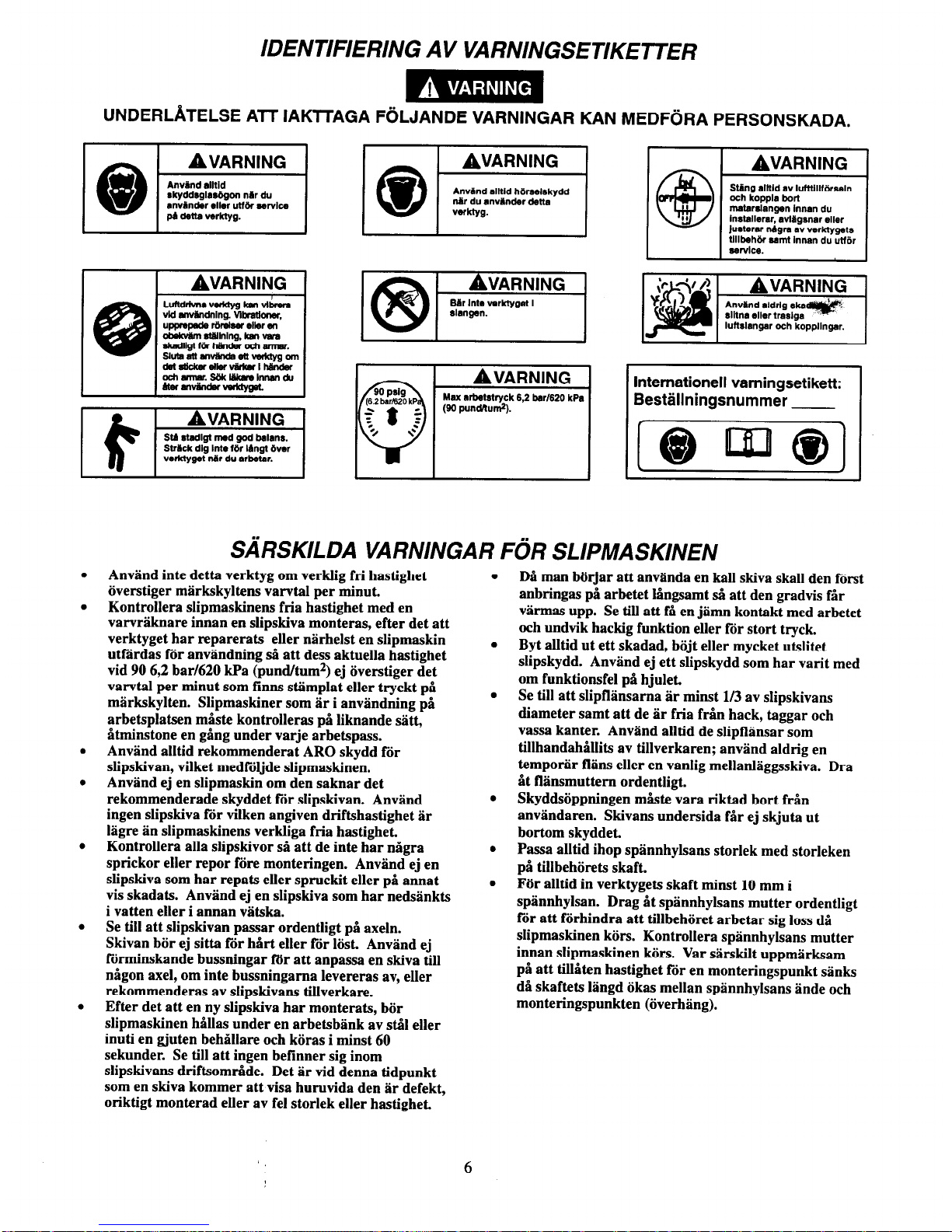
IDENTIFIERING AV VARNINGSETIKETTER
UNDERLATELSE ATT IAKlTAGA FOLJANDE VARNINGAR KAN MEDFORA PERSONSKADA.
SWVICB.
SARSKILDA VARNINGAR FOR SLIPMASKINEN
Anvand inte detta verktyg om verklig fri hastighet
iiverstiger markskyltens varvtal per minut.
Kontrollera slipmaskinens fria hastighet med en
varvraknare innan en slipskiva monteras, efter det att
verktyget har reparerats eller niirhelst en slipmaskin
utftirdas for anviindning sa att dess aktuella hastighet
vid 90 6,2 bar/620 kPa (pund/tum2) ej iiverstiger det
varvtal per minut som firms stimplat eller tryckt pH
mlrkskylten. Slipmaskiner som jir i anvjindning pH
arbetsplatsen mHste kontrolleras pH liknande sHtt,
Htminstone en gHng under varje arbetspass.
AnvHnd alltid rekommenderat ARO skydd for
slip&van, vilket medfiiljde slipmaskinen.
Anviind ej en slipmaskin om den saknar det
rekommenderade skyddet for slipskivan. Anviind
ingen slipskiva fdr vilken angiven driftshastighet Br
higre an slipmaskinens verkliga fria hastighet.
Kontrollera alla slipskivor sH att de inte har nHgra
sprickor eller repor fore monteringen. Anvjind ej en
slipskiva som har repats eller sprnckit eller pH annat
vis skadats. Anviind ej en slipskiva som har nedstinkts
i vatten eller i annan viitska.
Se till att slipskivan passar ordentligt pH axeln.
Skivan biir ej sitta fir hHrt eller for lost. Anvslnd ej
Fdrminskande bussningar fi5r att anpassa en skiva till
nPgon axel, om inte bussningama levereras av, eller
rekommenderas av slipskivans tillverkare.
Efter det att en ny slipskiva har monterats, biir
slipmaskinen hillas under en arbetsbiink av stil eller
inuti en gluten behHllare och kiiras i minst 60
sekunder. Se till att ingen befinner sig inom
slipskivans driftsomride. Det Hr vid denna tidpunkt
som en skiva kommer att visa huruvida den iir defekt,
oriktigt monterad eller av fel storlek eller hastighet,
.
.
.
.
.
.
6
D& man biirjar att anvtinda en kall skiva skall den forst
anbringas pH arbetet lbngsamt d att den gradvis fir
vslrmas upp. Se till att f& en jHmn kontakt med arbetet
och undvik hackig funktion eller for stort tryck.
Byt alltid ut ett skadad, biijt eller mycket utslitet
slipskydd. Anviind ej ett slipskydd som har vat-it med
om funktionsfel pH hjulet.
Se till att slipfliinsama tir minst l/3 av slipskivans
diameter samt att de iir fria f&n hack, taggar och
vassa kanter. Anviind alltid de slipflffnsar som
tillhandahHllits av tillverkaren; anvPnd aldrig en
tempo& fliins eller en vanlig mellanliiggsskiva. Dra
Ht BHnsmuttem ordentligt.
Skyddsiippningen m&e vara riktad bort frdn
anviindaren. Skivans undersida f&- ej skjuta ut
bottom skyddet
Passa alltid ihop spiinnhylsans storlek med storleken
pii tillbehijrets skaft.
For alltid in verktygets skaft minst 10 mm i
spiinnhylsan. Drag Ht splnnhylsans mutter ordentligt
for att fiirhindra att tillbehiiret arbetar sig loss dH
slipmaskinen k&s. Kontrollera splnnhylsans mutter
innan slipmaskinen kors. Var stirskilt uppmarksam
pH att tilliiten hastighet for en monteringspunkt sinks
dH skaftets Bingd iikas mellan splnnhylsans inde och
monteringspunkten (iiverhiing).

INNAN VERKNGET ANVANDS
SMORJNING
IRAX No. 10P
IRAX No. 50P
IRAX No. 68 1LB
Anvlnd alltid tryckluftssm&jare med dessa verktyg.
Vi rekommenderar foljande enhet som filtersmijrjarregulator:
Internationellt - IRAX Nr. C26-C4-A29
Efter varje tvH timmars drift, om en tryckluftssmorjare ej
anvlnds, skall l/2 till 1 cm301ja nr. 10P sprutas in i luftintaget.
KOMPRESSOR
(Bild. TPD905-1)
SPECIFIKATIONER
Modell
GH03A-35RC-6M-LP-EU
GH03A-30RC-6M-LP-EU
GH03A-20RC-6M-LP-EU
GHX03A-30RC-6M-LP-EU
Hastighet/
Spiinnhylsa
Ljudstyrkenivl Vibra-
varv per min.
dB (A)
tionsniva
tum mm Tryck Kraft
m/s2
32 000
l/4” 6
80.5
---
2.3
30000
1/4” 6
79.0
---
2.9
20 000
l/4” 6
75.1
---
4.9
30000
1/4” 6
79.0
---
2.2
Testad i enlighet med ANSI S5.1-1971 vid fri hastighet.
Testad i enlighet med ISO8662-1 med en artificellt obalancerad last med 50% av den godklnda hastigheten for verktyg utan
regulator, samt med 80% av den godkanda hastigheten for verktyg med regulator.
7
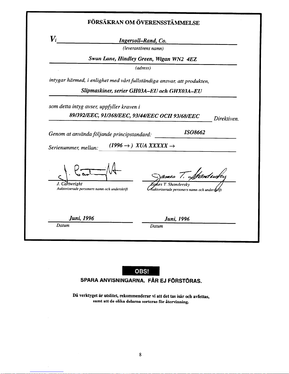
vi
Ingersoll-Rand, Co.
(leverantorens namn)
Swan Lane, Hind1ey Green, Wigan WN2 4EZ
(adress)
intygar harmed, i enlighet med vart fullstandiga ansvar, att produkten,
Slipmaskiner, serier GHO3A-EU och GHXO3A-EU
som detta intyg avser; uppfyller kraven i
89/392/EEC, 91/368/EEC, 93/44/EEC OCH 93/68/EEC
Direktiven.
Genom at anvanda foljande principstandard:
Serienummer, mellan:
(1996 - ) XUA XXXXX -
IS08662
Auktoriserade personers namn och underskrif
Juni, 1996
Juni, 1996
Datum
Datum
SPARA ANVISNINGARNA. FAR EJ FORSTORAS.
Da verktyget ar utslitet, rekommenderar vi att det tas isar och avfettas,
samt att de olika delama sorteras for Htervinning.
8
ARO
BRUKERHANDBOK
6-1996
Tool Products
0
N
SERIEN GH03A-EU OG GHX03A-EU SLIPEMASKINER
Serie GH03A-EU og GHX03A-EU slipemaskiner er konstruert for arbeide i trange forhold i jern
og metallindustrien, skipsverft, rorfabrikasjon, stoperier og andre arbeidsomreder med liten
plass. De er spesielt skikket til arbeider hvor ledningskanaler, ror, andre kanaler osv. passerer
gjennom skott og rammeverk. Disse sma slipemaskinene er meget effektive til a slipe svei-
sepaleggstreng og vil etterlate en fin overflate.
ARO er ikke ansvarlig for verktoymodifikasjoner som utfores av kunden hvor ARO ikke er
rbdspurt.
INNEHOLDER VIKTIG SIKKERHETSINFORMASJON.
LES DENNE INSTRUKSJONSHANDBOKEN FOR VERKTOYET TAS I BRUK.
DET ER ARBEIDSGIVERENS PLIKT A GI INFORMASJONEN I DENNE
INSTRUKSJONSBOKEN TIL BRUKEREN.
PERSONSKADER KAN OPPSTA HVIS IKKE FOLGENDE ADVARSLER BLIR EITERKOMMET.
FBRSTEGANGSBRUK AV VERKTOY BRUK AV VERKT0Y
Bruk, inspiser og vedlikehold alltid dette verktoyet i
folge eksisterende lokale og nasjonale forskrifter for
handholdt/handbetjent trykkluftverktoy.
For best sikkerhet, topp ytelse og maksimal levetid pa
deler her dette verkteyet brukes ved maksimalt lufttrykk pa 6,2 bar/620 kPa (90 psig) milt ved luftinntaket nar en 8 mm (5/16 tomme) innvendig diameter
trykkslange brukes.
Steng alltid av lufttilferselen og koble fra lufttilforselslangen for installering, fjeming eller justering av tilbehor, eller fer vedlikehold blir utfert pH
dette verktoyet.
Bruk ikke en skadet, sprukket eller slitt luftslange/
kobling.
Sorg for at alle slanger og koblinger er av riktig
sterrelse og er tette. Se tegning TPD905-1 for et
typisk koblingsarrangement.
Bruk alltid ren, torr luft ved 90 psig maksimalt lufttrykk. Stov, etsende gasser og/eller for mye fuktighet
kan sdelegge motoren pa et trykkluftverktoy.
Smar ikke verkteyene med brennbare eller ustabile
vcesker som parafin, diesel eller flybensin.
Fjern ikke noen identifikasjonsmerker. Skift ut skadete merker.
.
.
.
.
.
.
.
.
.
.
Bruk alltid vemebriller under arbeid med eller vedli-
kehold av dette verktoy.
Bmk alltid harselvem under arbeid med dette
verktoy.
Hold hender, lese kher og langt har unna rotasjonsdelen pa verktoyet.
Fomtse og veer forberedt pH plutselige bevegelsesforandringer ved oppstart og bruk av ethvert trykkluftverkt0y.
Hold kroppen i en balansert og fast stilling. Len deg
ikke for langt forover under bruken av dette
verktoyet. Hoye reaksjonsmomenter kan forekomme
ved lavere lufttrykk enn det som er anbefalt.
Verkteytilbeheret kan fortsette H rotere etter at av/pH
hHndtaket er sluppet.
Trykkluftverktey kan vibrere under bruk. Vibrasjon,
gjentatte bevegelser eller ubekvemme stillinger kan
were skadelig for hender og armer. Starts bruken av
ethvert verktoy ved ubehag, stikkende folelser eller
hvis du fhr smerter. Sok rad fra lege for videre arbeid
gjenopptas.
Bruk tilbeher som er anbefalt av ARO.
Dette verkteyet er ikke beregnet til bruk pa steder der
det er fare for eksplosjon.
Dette verktoyet er ikke isolert mot elektriske stot.
Bruk av andre deler enn originale ARO-reservedeler kan fore til sikkerhetsrisiko, redusert verktoyytelse og okt
vedlikehold, og kan fore til at garantien blir ugyldig.
Reparasjoner her bare utfores av autorisert personell. Spor hos ditt naermeste autoriserte ARO Tool Product,+reparasjonssenter.
For opplysninger om deler og service vennligst kontakt din lokale ARO-distributor.
ARO Tool Products
Ingersoll-Rand Company
SWAN LANE. HINDLEY GREEN. WIGAN, UK WN2 4EZ
ARO
0942-57131
l
FAX 0942-55045 © 1996
INGERSOLL-RAND COMPANY
Trykt i U.S.A.
Del av verdensomspennende lngersoll-Rand
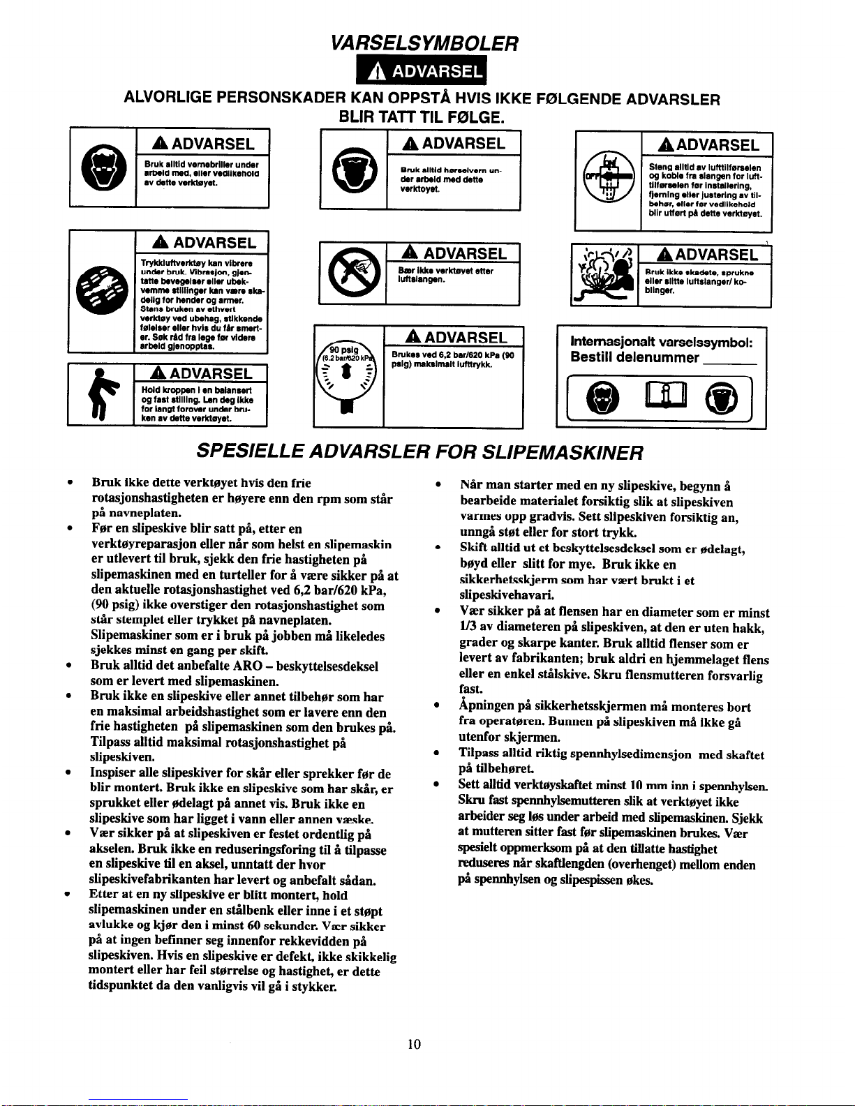
VARSELSYMBOLER
ALVORLIGE PERSONSKADER KAN OPPSTA HVIS IKKE FOLGENDE ADVARSLER
BLIR TATT TIL FOLGE.
lntemasjonalt varselssymbol:
Bestill delenummer
SPESIELLE ADVARSLER FOR SLIPEMASKINER
Bruk ikke dette verkteyet hvis den frie
rotasjonshastigheten er heyere enn den rpm som s&r
pH navneplaten.
Fgr en slipeskive blir satt pH, etter en
verkt@yreparasjon eller nHr som heist en slipemaskin
er utlevert til bruk, sjekk den frie hastigheten pH
slipemaskinen med en turteller for H were sikker pi at
den aktuelie rotasjonshastighet ved 6,2 bar/620 kPa,
(90 psig) ikke overstiger den rotasjonshastighet som
stir stemplet eller trykket pH navneplaten.
Slipemaskiner som er i bmk pH jobben ml likeledes
sjekkes minst en gang per skift.
Bruk alltid det anbefalte ARO - beskyttelsesdeksel
som er levert med slipemaskinen.
Bmk ikke en slipeskive eller annet tilbehfir som har
en maksimal arbeidshastighet som er lavere enn den
frie hastigheten pH slipemaskinen som den bmkes pH.
Tilpass al&id maksimal rotasjonshastighet pH
slipeskiven.
Inspiser alle slipeskiver for skHr elier sprekker far de
blir montert. Bmk ikke en slipeskive som har skHr, er
spmkket eller Bdelagt pH annet vis. Bmk ikke en
slipeskive som har ligget i vann eller annen vzske.
Veer sikker pH at slipeskiven er festet ordentlig pH
akselen. Bruk ikke en reduseringsforing til H tilpasse
en slipeskive til en aksel, unntatt der hvor
slipeskivefabrikanten har levert og anbefalt sbdan.
Etter at en ny slipeskive er blitt montert, hold
slipemaskinen under en stibenk eller inne i et stept
avlukke og kjer den i minst 60 sekunder. Vzr sikker
pi at ingen befinner seg innenfor rekkevidden pH
slipeskiven. Hvis en slipeskive er defekt, ikke skikkelig
montert eller har feil sterrelse og hastighet, er dette
tidspunktet da den vanligvis vi1 gH i stykker.
NHr man starter med en ny slipeskive, begynn H
bearbeide materialet forsiktig slik at slipeskiven
varmes opp gradvis. Sett slipeskiven forsiktig an,
unngH stet eller for stort trykk.
Skift al&id ut et beskyttelsesdeksel som er Bdelagt,
boyd eller slitt for mye. Bmk ikke en
sikkerhetsskjerm som har vaxt bmkt i et
slipeskivehavari.
Vazr sikker pH at flensen har en diameter som er minst
1/3 av diameteren pH slipeskiven, at den er uten
hakk,
grader og skarpe kanter. Bmk alltid flenser som er
levert av fabrikanten; bmk aldri en hjemmelaget flens
eller en enkel sdlskive. Skru flensmutteren forsvarlig
fast.
Apningen pH sikkerhetsskjermen rni monteres bort
fra operateren. Bunnen pB slipeskiven mH ikke gi
utenfor skjermen.
Tilpass alltid riktig spennhylsedimensjon med skaftet
p& tilbehtiret.
Sett alhid verkteyskaftet miust 10 mm inn i spennhylsen.
Skru fast spennhylsemutteren slik at verkteyet ikke
arbeider seg los under arbeid med slipemaskinen. Sjekk
at
mutteren sitter fast for slipemaskinen brukes. Veer
spesielt oppmerksom pH at den tillatte hastighet
reduseres nar skafflengden (overhenget) mellom enden
pi spennhylsen og slipespissen ekes.
10
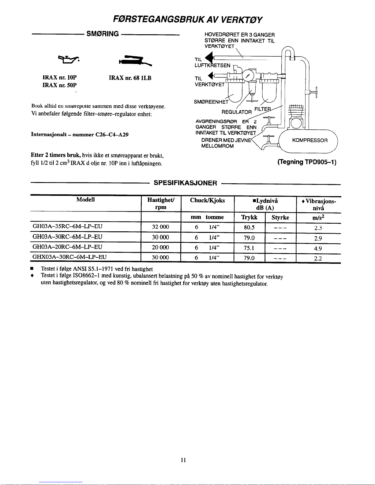
F0RSTEGANGSBRUK AV VERKT0Y
SMORING
HOVEDR0RET ER 3 GANGER
ST0RRE ENN INNTAKET TIL
VERKT0YET \
n
IRAX nr. 10P
IRAX nr. 50P
IRAX nr. 68 1LB
Bruk alltid en smarepotte sammen med disse verktoyene.
Vi anbefaler folgende filter-smore-regulator enhet:
Intemasjonalt - nummer C26-U-A29
DRENER MED JEVN
KOMPRESSOR
MELLOMROM
Etter 2 timers bruk, hvis ikke et smareapparat er brukt,
fyll 1/2 til 2 cm3 IRAX d olje nr. 10P inn i luftipningen.
(Tegning TPD905-1)
SPESIFIKASJONER
Modell
Hastighet/
Chuck/Kjoks
n
Lydnivl
Vibrasjons-
rpm
dB (A)
niva
mm tomme
Trykk
Styrke
m/s2
GH03A-35RC-6M-LP-EU 32 000 6
l/4”
80.5
---
2.3
GH03A-30RC-6M-LP-EU 30000 6
l/4”
79.0
---
2.9
GH03A-20RC-6M-LP-EU 20000 6
l/4”
75.1
---
4.9
GHX03A-30RC-6M-LP-EU 30000 6
l/4”
79.0
---
2.2
Testet i folge ANSI SS.l-1971 ved fri hastighet
Testet i folge ISO8662-1 med kunstig, ubalansert belastning pb 50 % av nominell hastighet for verktoy
men hastighetsregulator, og ved 80 % nominell fri hastighet for verktoy uten hastighetsregulator.
11

KONFORMITETSERKLAZRING
vi
Ingersoll-Rand, Co.
(leverandorens navn)
Swan Lane. Hindley Green, Wigan WN2 4EZ
(adresse)
erklaerer pa aere og samvittighet at produktet,
Serie GHO3A-EU og GHXO3A-EU slipemaskiner
som denne erklaeringen gjelder for, oppfyller bestemmelsene i
89/392/EEC, 91/368/EEC, 93/44/EEC OG 93/68/EEC
direktivene.
ved a bruke folgende prinsipielle standarder:
Serienr: :
(1996 - ) XUA XXXXX -
IS08662
Navn og underskrift til autoriserte personer
Juni, 1996
Juni, 1996
Dato Dato
OPPBEVAR DISSE INSTRUKSJONENE. ODELEGG DEM IKKE.
Nar verktoyet ikke lenger er brukbart, anbefales det at verktoyet blir demontert,
rengjort for olje og sortert etter materialer i gjenvinningsnryemed.
12
ARO KAYTTAJAN OPAS
Tool Products
6-1996
0
I
GH03A-EU- JA GHX03A-EU -SARJAN HIOMAKONEISIIN
GH03A-EU- ja GHX03A-EU -sarjan hiomakoneet on tarkoitettu kiiytetttiviksi ahtaissa paikoissa tapahtuvaan tyijstijijn metalliteollisuudessa, telakoilla, putkien valmistuksessa, takomuottien ja valumuottien
valmistuksessa ja monissa sellaisissa tyWaiheissa, joissa ty&tBiin kiiytetty tila on hyvin rajattu.
TyGkalut ovat erityisen kiiytt6kelpoisia sovelluksissa, joissa johdinkanavat, ilmastointikanavat, putket
tms. kulkevat laipioiden tai muiden merkitttivien kantavien rakenteiden Ilpi. NIml pienet hiomakoneet
ovat myb hyvin tehokkaita koneita hitsisaumojen hiomisessa ja niiden avulla saadaan aikaiseksi hyvin
viimeistelty pinta.
ARO ei ole vastuussa tyiikalujen mahdollisista modifikaatioista muihin sovelluksiin, joista ARO ei ole
tiedoitettu.
OHJEISSA ON MUKANA TiiRKElTii TURVAOHJEITA.
LUE TiiMli OHJEKIRJA ENNENKUIN ALAT KAYmiiii TYiiKALUJA.
TYGNANTAJAN VELVOLLISUUS ON SAA-l-FAA TiiMii
OHJEKIRJA TYijNTEKIJolDEN TIETOON.
SEURAAVIEN VAROITUSTEN LAIMINLY6MINEN SAAlTAA JOHTAA VAMMAUTUMISEEN.
TYOKALUJEN KiivrrijijNOTrO
TY6KALUN tiYlT6
Kayti, tarkasta ja huolla tiCi tySkalua aina kaikkien
kHsikslyttSisiin ilmanpaineella toimiviin tyiikaluihin
liittyvien sHjinniisten mukaisesti (Tyiiturvallisuuslaitoksen mliiriiykset yms.)
KIyti tyiikalua eninti5n 6,2 bat-in tyiipaineella ja liiti
se 8 mm (5116”) paineilmaletkuun, jotta tyiikalu toimisi mahdollisimman tehokkaasti, turvallisesti ja
pitkiiik5isesti.
Kytke paineilma aina pois psliilti ja irroita paineilmaletku ennen kuin asennat, poistat tai siijidiit miWn
t&m&t tyiikalun lisiilaitetta tai ennen kuin alat huoltaa
tyokalua.
All kiiyti vahingoittuneita, hankautuneita tai kuluneita paineilmaletkuja tai -liittimil.
Vannistu, ettii kaikki paineilmaletkut ja -liittimet
ovat oikeaa kokoa ja ne ovat tiiviisti kiinni. Katso ku-
vasta TPD905-1 kaaviota tavanomaisesta paineilma-
kytkennbti.
Kiiyti aina puhdasta, kuivaa paineilmaa, jonka Paine
on enintiiin 6,2 bar. Piily, ruostehiiyryt ja/tai liika
kosteus saattavat vahingoittaa tySkalun paineilmamoottoria.
Ala voitele tyiikalua tulenaroilla tai helposti haihtuvilla nesteilhi, kuten dieseliiljylhi, kerosiinilla tai JetA-polttoaineella.
Alii poista mit&in tyiikalussa olevia tarroja. Vaihda
vahingoittuneet tarrat.
.
.
.
.
.
.
.
.
.
.
Kliyti aina suojalaseja tyiikalua kaytt%esslsi tai huoltaessasi.
KHytii aina kuulosuojaimia tySkalua klyttiesslsi.
Pidii ktidet, irtonainen vaatetus ja hiukset loitolla
tySkalun pySrivjistii p&t&
Ennakoi ja varo tyi5kahm kiiynnistyksen ja kiiytiin aikana
ty&ahm liikkeiden ja voimien i&kin&i% muutoksia.
Seiso tukevassa asennossa hyviissH tasapainossa. Ahi
kurkota k5yttiesslsi tyiikalua. l@kaluun saattaa
ylliittien tulla voimakkaita vliintiiliikkeiti
sekH
suosi-
tellulla ilmanpaineella etti siti pienemmHllH paineella
toimittaessa.
TySkalun 1isHlaitteet saattavat pySril viehi hetken
aikaa kslynnistimesti irtipiihtimisen jllkeenkin.
Paineilmatyokalut voivat Grist5 toimiessaan. THrinL,
toistuvat liikesarjat tai epHmiellyttivHt asennot saattavat olla vahingollisia kiisillesi ja ktisivarsillesi. Lopeta
tyiikalun kayttii, jos alat tuntea kihelmiiintiii ja kipua.
KHHnny hbikiirin puoleen ennen kuin
jatkat
tyiikalun
kiiyttiiii.
Kiiyti ARO suosittelemia IiGilaitteita.
Ttimii tyiikalu ei ole suunniteltu klytettivlksi
riijjihdysalttiissa ymplristiiissl.
Tiimji tySkalu ei ole eristetty dhkoiskujen varalta.
Muiden kuin ARO alkupertiisvaraosien kjiyttii saattaa johtaa vaaratilanteisiin, heikentyneisiin tyokalun suoritusarvoihin,
kasvavaan huollontarpeeseen ja se saattaa mitiitiiidff kaikki takuut.
Ainostaan valtuutetun, koulutetun henkiliistiin tulisi korjata tyiikalua. Lisiitietoja saat liihimmiisti ARO Tool Products merkkihuoltokeskuksesta.
Varaosiin ja huoltoon liittyviin kysymyksiin vastaa paikallinen ARO-edustaja.
ARO Tool Products
Ingersoll-Rand Company
ARO
SWAN LANE. HINDLEY GREEN. WIGAN, UK WN2 4EZ
094257131
.
FAX
0942-55045 @ 1996 INGERSOLL-RAND COMPANY
Painettu Amerikan Yhdsysvalloissa
Osa maailmanleajuists Ingersoll-Rand -ryhmiiii

VAROITUSTARROJEN TULKINTAOHJEITA
SEURAAVIEN VAROITUSTEN LAIMINLYtiMINEN SAAlTAA JOHTAA VAMMAUTUMISEEN.
tilrlattl tdmlersaan. Ttirlnll,
tolstuvat lllkeaar~t tai ep&imld.
lyltiivtlt a8emmt saattavat olla
vahlngdllrla ktislll~sl Ja Mslvardllesl. Lopeta tybkalun
kllytttl jar alat tuntea kl-
1 AVAROITUS 1
I
Alit karma ty&ikalua palnell-
~IStkUSttL.
I
AVAROITUS
Kytke palndlma alna pds
piNIt Ja lrrolta
palndlmaletku annen kuln
arennat. pdrtat tal s&&t&
mltlllln titmhn tybkalun
Ildllaltetta tal enn@n kuin
alat huoltaa ty6kalua.
Kansainvtilinen varoitustarra:
Osanumero
[-liimm]
ERINISESTI HIOMAKONEISIIN LlllTYVA’T VAROITUKSET
Ahi kffyti tit& tyiikalua, jos tyiikalun vapaa nopeus
ylittiii nimikilvessH mainitun kierrosnopeuden.
Ennen kuin asennat koneeseen tySstiipHPn (laikan
tms.), aina korjausten jjilkeen ja kun kone
ensimmiliseksi otetaan kiiyttiiiin, tarkasta koneen
vapaa kierrosnopeus kierroslukumittarilla. Varmistu,
etti vapaa nopeus 6,2 barin ilmanpaineella ei yliti
koneen nimikilvessa mainittua kierrosnopeutta.
KHytiissH olevat koneet on tarkastettava samalia
tavalla vHhinti3in kerran tytivuoron aikana.
Kiiyt.5 aina koneen kanssa ARO suosittelemaa
tySstiip%in suojaa.
Ala kHytii hiomakonetta ilman suositeltua
laikansuojusta. Ahi kiiyti mititin sellaista laikkaa,
jonka suojassa suositeltu kierrosnopeus on pienempi
kuin hiomakoneen vapaa nopeus.
Tarkasta aina ennen tyiin aloittamista tyiistilaikoissa
olevat sjiriit ja halkeamat. Ahi ktiyti laikkaa, joka on
halkeillut, $CCttynyt tai jossa nakyy muita
vaurioita. Alli kayt5 laikkaa, joka on kastunut vedessa
tai muussa nesteess5.
Varmistu siiti, etti hiomakoneen laikka sopii
asianmukaisesti tyiikalun vat-teen. Ala kiiyti jyrsimen
ja laikan viilissii sovitepuslia, ellei tiima sovite ole
nimenomaan laikan valmistajan suosittelema tai
toimittama.
Uuden laikan asentamisen jtilkeen k5yG-i konetta
yhden minuutin ajan tyiipenkin alla tai jonkun
terlisrakenteen sis%llL Varmistu, etti kukaan ei ole
laikan tyiistiitasossa tin% aikana. Jos laikka on
viallinen, huonosti asennettu, viiiran kokoinen tai sita
. . . . . .
. .
kiiytet58n vaaralla nopeudella, se yleensa hajoaa
ensimmiiisen kHyttiiminuutin aikana.
Kun aloitat tyiistiin kylmiilhi laikalla, tyiisti pienellii
paineella ja kitkalla, kunnes laikka viihitellen
himpenee. Koeta saada aikaan pehmea kontakti laikan
ja tyiikappaleen vllillii ja viilti takovaa liiketti ja
kovaa painetta.
Vaihda aina vahingoittuneen, taipuneen tai hyvin
kuluneen tySstiipGn suojan tilalle uusi. Ahi kayta
suojaa,
joka
on joskus ollut kiiyt&sP laikan
hajoamisen yhteydessii.
Varmistu, etti laikkojen laippojen lapimitta on
viihint%in l/3 laikan liipimitasta ja etti laipoissa ei ole
iskujiilkiii, syviii naanuuja tai teriivil siirmil. KIytH
aina laikan vahnistajan toimittamia laippoja; ahi
koskaan kiiyti itse tehtyja laippoja tai tavallisia
aluslevyja. Kiristi laipan mutteri lujasti.
Tyiistiipii%t suojan avoimen osan tiytyy aina olla
poispiiin koneen kiiyttijbti. Laikan alaosa ei saa tulla
ulos suojasta.
Ktiyti aina oikean kokoista kiristysistukkaa, joka
vastaa tySkalun varren kokoa.
Tyiinnff tyiikalu aina vjihintitin 10 mm kiristysistukan
sisGn. Kiristi istukan mutteri lujasti, jotta tyiikalu ei
pllsisi kHyti5n aikana valumaan ulosplin istukasta.
Tarkasta kiristysmutterin tiukkuus ennen kuin alat
kiiyttisl konetta. Kiinnit5 erityistii huomiota siihen,
ettil kiinnekohdan maksimi sallittu kierrosnopeus
alenee, kun kiristysistukan ja kiinnekohdan vllisen
varren pituus kasvaa (ylitys).
14

TYOKALUN tdiYTT6liNOlTO
VOITELU
. .
PAAPAINEILMALINJA LAPIMITALTAAN
KOLME KERTAA PAlNElLtvlATYdKALUN
LIITINAUKON KOKOINEN
w*
PAl~~~RJEsTELM~N\ h
-
IRAX No. 1OP
IFUX No. 50P
IRAX No. 68 1LB
Kaytl aina paineilmavoitelua tyijkalujen yhteydessa.
Suosittelemme seuraavaa suodatin-voitelu-paineensaath
-yhdistelmllaitetta:
PAINEILMAN HAARALINJ
LAP~MITALTAAN KAK~I KER-
Kansainvfflisessji kiiytissti - IRAX C26C4-A29
TAA PAlNElLMATYCjK
LIITINAUKON KOK
KOMPRESSORI
Ruiskuta 112 - 1 cm3 Ingersoll-Rand 1OP iiljya paineilman
tuloaukkoon aina kahden kiiyttiitunnin viilein, miklli
paineilmajajestelmlssP ei ole paineilmavoitelua.
(Kuva TPD905-1)
ERIITELY
Malli
Vapaa nopeus
Kiristys-
WMelutaso
l
VlrinP
Urnin istukka
dB (-4
mm (tuumaa) Paine
Teho
m/s2
GH03A-35RC6M-LP-EU
1 32 ooo 1 6 WI” 1 80.5 1 -- - 1 2.3
I
GH03A-30RC-6M-LP-EU
30000
6 l/4”
79.0
---
2.9
GH03A-20RC6M-LP-EU
20000
6 l/4”
75.1
---
4.9
GHX03A-30RC-6M-LP-EU
30 000
6 l/4”
79.0
---
2.2
n
Koestettu ANSI S5.1-1971 mukaisesti vapaalla kierrosnopeudella.
+ Koestettu ISO8662-1 in mukaisesti keinotekoisella, tasapainottamattomalla kuormalla.
Nopeus 50% nimellisnopeudesta tyakaluille ilman sladinta ja 80% ty6kaluille, joissa on sladin.
15

VAKUUTUS NORMIEN T;iYTT;iMISEST;i
Mf?
Ingersoll-Rand, Co.
(toimittajan nimi)
Swan Lane, Hindlev Green, Wigan WN2 4EZ
(osoite)
vakuutamme ja kannamme yksin tiiyden vastuun siitli, ettti tuote
GHO3A-EU- ja GHXO3A-EU -sarjan hiomakoneet
johon ttimli vakuutus viittaa, tiiyttiiii direktiiveissii
89/392/EEC, 91/368/EEC, 93/44/EEC ja 93/68/EEC
esitetyt vaatimukset seuraavia perusnonneja kiiytetttiessii:
Sarjanumerot:
(1996 + ) XUA XXXXX +
IS08662
>
Autorisoidun henkilbn nimi
Kesiikuu, 1996
Kesiikuu, 1996
Piiiv2iy.s
Piiiviiys
. .
. .
SAASTA NliMii OHJEET. iiLii TUHOA NIITji.
Kun timtin tyiikalun ktiyttiiikti on loppunut, suosittelemme tyiikalun purkamista, puhdistusta rasvasta ja eri
materiaalien erittelyii kierrlitystl vat-ten.
16

ARO
MANUAL DO OPERADOR
Tool Products
RECTIFICADORES SERIE GH03A-EU E GHX03A-EU
6-1996
0
P
OS Rectificadores S&ie GH03A-EU e GHX03AIU Go concebidos para trabalho em espacos
restritos na industria de moldagem de metal, em estaleiros, fabrica@o de tubos, fabrica@ de
matrizes e moldes e aplica@es corn espaco limitado. so especialmente bons onde condutas,
canaliza@es, tubos etc. passam atraves de paredes ou arma@es. Estes pequenos Rectificadores
&o muito eficazes para rectificar pontos de soldadura e deixar uma acabamento polido.
A ARO n5io pode ser responsabilizada pela modifica@o de ferramentas para aplica@es para as
quais ntio tenha sido consultada.
IMPORTANTES INFORMACCES DE SEGURANCA EM ANEXO.
LEIA ESTE MANUAL ANTES DE OPERAR A FERRAMENTA.
E RESPONSABILIDADE DA ENTIDADE PATRONAL P6R AS INFORMACCES
CONTlDAS NESTE MANUAL A DISPOSICAO DOS UTlLIZADORES.
A NAO OBEDIENCIA AS ADVERTENCIAS SEGUINTES PODERA RESULTAR EM LESdES PESSOAIS.
COLOCACAO DA FERRAMENTA EM SERVlCO
Opere, inspeccione e fap manuten@o nesta ferramenta
sempre de acordo corn todos 0s mgulamentos (locais,
estataiq federais e nacionais) que possam ser apli&veis
a ferramentas pnemmiticas de hmcionamento manual.
Para seguran~ desempenho superior e durabiidade
mkima das M open2 esta ferramenta a uma prws50
de ar m%ma de 90 psig (6,2 bar-1620 kPa) na admiss
corn tuna mangueira de alimenta@o de ar corn diketro
intern0 de 916 pol. (8 mm).
Desligue sempre a alimenta@o de ar e a mangueira de
alimenta@o de ar antes de i&alar, ret&u ou ajustar qualquer aces&i0 desta ferramenta, ou antes de fazer manuten@io na mesma.
Niio utilize maugueiras de ar e ace&r& danificados,
puidos ou deteriorados.
Certifique-se de que todas as mangueiras e aceskics Go
da dimen. curmcta e que est5.0 segurus firmemente.
Cons&e o Des. TPD!NS-1 para uma disposi@o de tubas
tipica.
Utilize sempre ar limp0 e seco a uma pmss50 mkima de
90 pig. Poeira, fumes cormsivos e/au hum&de excesiva
podem destmir o motor de uma ferramenta pneumsitica.
Ngo lubtifique a ferramenta corn liquidos inflamkeis ou
vol&eis coma quetosene, gas&o ou combustfvel para jactos.
.
Niio reline nenhum r&do. Substitua 0s r6tulos danificados.
UTlLlZACAO DA FERRAMENTA
Use sedpre protec@o para 0s olhos a0 operar ou fazer
manuten@o nesta ferramenta.
Use sempre pnAec@o amicular a0 operar esta ferramenta.
Mantenha as m&s, roupas soltas e cabelos longos afastados da extrwnidade totativa da ferramenta
Psteja preparado e alerta para mudancas slibitas no movi-
mento dumnte o arranque e o funcionamento de qualquer
ferramenta me&&a.
Manteuba o corpo numa posi@io equilibrada e &me. Ngo
estique 0 corpo a0 operar esta ferramenta. Podem ocorrer
binkios de teac@o elevados a ou abaixo da press50 do ar
recomendada.
OS acesskios da ferramenta podem continuar a radar por
um auto pdodo de tempo depois de sohar o regulador.
A ferramentas pneumriticas podem vibrar durante a utili-
z.a@o. Vibra@o, movimentos npetitivos ou posi@es descouforthveis podem ser nocivos L suas mks e braces.
Pare de utilizar qualquer ferramenta se ocorrer desconforto, seusag50 de formigueiro ou dor. Procure a&stGncia
mkdica antes de reiniciar a utiliza@~o.
Use os acesskios recomendados pela ARO.
Esta ferramenta tie 6 concebida para funcionar em atmosferas explosives
Esta fenamenta 1150 C isolada contra choque elktrico.
A utiliza@o de qualquer pep sobresselente que nHo seja ARO genuina pode resultar em riscos para a seguranca, em
desempenho reduzido da ferramenta e mais necessidade de manuten@o, e pode invalidar todas as garantias.
As repara@es so devem ser feitas por pessoal autorizado e corn forma+o adequada. Consulte o Representante Autorizado
ARO Tool Products mais proximo.
Para obter informagbes sobre peGas e assisthcia, contacte o seu distribuidor local ARO.
ARO Tool Products
Ingersoll-Rand Company
ARO
SWAN LANE l HINDLEY GREEN. WIGAN, UK WN2 4EZ
0942-57131
l
FAX
0942-55045 @ 1~6 INGERSOLL-FIANO COMPANY
Impress0 nos E.U.A.
Parte da Ingersoll-Rand a nivel mundial

IDENTlFlCA@iO DAS ETIQUETAS DE ADVERTENCIA
A NAO OBEDIENCIA I\S ADVERTENCIAS SEGUINTES PODERA RESULTAR EM LES6ES PESSOAIS.
iA
ADVERTENCIA 1
b--e
vlbrudummslltimQ6o.
wbmQ&,mwi-mpe66vos
I Lgypd”
flOCNULNlOSWl&SS
bncor --~~~qrulquar
kNMWtfSSS--MO,
ssnsqadetorm~rocudor.
-sssls&ncismmiumws
ds mlnidv . u6lll.
I
ADVERTeNCIA
Use sentpre protac*
aurlCular so opwsr esu
krrarwnts.
A ADVERTENCIA
opare a “nts press60 dear
rMdt’t’t~ ds 90 pslg (6,2 bar/
1” ADVERTENCIA
Desligua sempre * alimenta~io
dssraamsngueirade
dis dear antes de
instslar, rmwver w sjustar urn
acess6rlo dests fensmenta, 0”
snter de fazer manuteqlo na
-Illa.
Etiqueta lnternacional de Advertihcia:
NQ de PeGa para Encomenda
ADVERTENCIAS ESPECl-FICAS PARA 0 RECTIFICADOR
NHo utilize esta ferramenta se a velocidade livre wd
ultrapassar o valor de rpm indicado na placa de
identitka@o.
Antes de montar mna m6 abrasiva, ap6s qualquer
repara@o da ferramenta ou sempre que o Rectikador
for ser utilizado, veritlque a velocidade like do mesmo
corn mn taquimetro para assegurar que a sua velocidade
real a 90 psig (6,2 bar/620 kPa) n50 ulhapasa o valor de
rpm gravado ou impress0 na placa de identi&a@o. OS
rectificadores em uso mnna tarefa devem ser verificados
da mesma maneira, pelo meno uma vez em cada turno.
Utilize sempre a Protec@o de M6 Abrasiva ARO
recumendada e fomecida corn o Rectificador.
N%o utilize mna m6 abrasiva, rebarbador ou outro
aces&i0 que tenha uma velocidade nxkima de
funcionamento abaixo da velocidade livre do Rectilicador
no quai o aces&i0 esG a ser u&ado. Obedg sempre
a0 valor m&&n oderpmespwificadonasanilhasdasn&
abrasivas.
lnspcrione todas as m& abrasivas quanto a lascas ou
rachas antes de as montar. NHo utilize uma m6 que esteja
lascada, rachada, ou danikada de alguma maneira. N5o
utilize mna m6 que tenha e&do mergulhada em &ua ou
em outro Equido qualquer.
Certitiquese de que a m6 abrasiva encaixa
comxtamente no veio. Nb utilize buchas lpdutoras para
adaptar uma m6 abrasiva a um veio, a menos que a
bucha seja fomecida e recomendada pelo fabricante da
m6.
Depois de montar uma m6 abrasiva nova, segum o
Rectifiaulor sob tuna bancada de ap ou dentro de uma
pep fundida e ponha-0 a funcionar durante pelo menus
60 segundos Certifiquw de que n&o hd ninguim dentro
do phmo de opera@0 da m6 abrasiva. Se mna m6 estiver
corn defeito, montada incorrectamente ou for de tamanho
ou velocidade errada, C gerahnente nesta altura que ela
falhans.
18
Ao comgar a trabalhar corn uma m6 fria, aplique-a ao
trabalho lentamente, ati a m6 aquecer graduahnenk
Fap contact0 suave corn o trabalho e evite qualquer
ac@o ins&e1 ou pnzs50
excessiva
Subslitua sempre uma pmtec@o de m6 abrasiva
danificada, curvada ou muito gasta. N5o utilize uma
prote+o que tenha side sujeita a uma falha de m6
abrasiva
Certifique-se de que as flanges da m6 ti?m pelo menos l/3
do di&netm da m6 abrasiva, estio livres de entalhes,
rebarbas e bordas afiadas. Utilize sempre as flanges de
m6 fomesidas pelo fabricante; nunca utilize mna flange
improvisada ou uma anilha comum. Aperte a Flange da
M6 firmemente,
A abertura da p~te@o deve ficar voltada para longe do
operador. 0 fundo da m6 1150 deve Bear saliente alCm da
protec@o.
Fap sempre a corwpondkia da dime&o do mandril
corn a dime&o da haste do acesskio.
Introduza sempre a haste da ferramenta pelo menos 10
mm no mandril. Aperte a Porm do Manti firmemente
para evitar que o aces&i0 se desloque durante a
opera@0 do Rectilicador. Verifique o aperto da Porca do
Mandril antes de p6r o Rectificador em funcionamento.
Preste atengo espe&l ao facto de que a velocidade
permitida de mn ponto montado 6 reduzida quando o
comprimento do veio B aumentado entre a extremidade
do mandril e o ponto montado @rojec@o).

COLOCA(d0 DA FERRAMENTA EM SERVICO
LUBRIFICACAO
PARA 0
SISTEMA
DE AR
LINHAS PRINCIPAIS - 3 VEZES
A DIMENSAO DA ADMlSSiiO DA
FERRAMENTA PNEUMATICA
IRAX w lo?
IRAXN”68 1LB
IRAXWSOP
Utilize sempre urn lubrificador de linha de ar corn estas
ferramentas.
Recomendamos a seguink Unidade
Filtr+Lubrificador-Regulado~
LINHA SECUNDARIA -
Para Intemacional - IRAX W C26-GL429
2 VEZES A DIMENSAO
DA ADMISSAO DA
FERRAMENTA
COMPRESSOR
Ap6s cada duas horas de funcionamento, se nb estiver a ser
PNEUMATICA
utilizado urn lubrificador de linha de ar, injecte l/2 a 1 cc de &to
lRAXN”lOPnaAdmiss%odoAr.
DRENAR y
REGULARMENTE
(Des. TPD905-1)
ESPEClFlCA@ES
Modelo
Velocidade/
Mandril
n
Nive1 de Som
+ Nivel de
rpm
dB (A)
VibragBes
pol. mm
Presdo
PotCncia
m/s2
GH03A-35RC-6M-LP-EU
32 000
l/4”
6
80.5
---
2.3
GH03A-30RC-6M-LP-EU
3oooo
l/4”
6
79.0
---
2.9
GH03A-20RC-6M-LP-EU
20000
l/4”
6
75.1
---
4.9
GHX03A-30RCAM-LP-EU
30 000
l/4”
6
79.0
---
2.2
n
Testada de acordo corn ANSI S5.1-1971 a velocidade livre
+
Testada de acordo corn ISO8662-1 corn carga artificial desequilibrada a 50% da velocklade nominal pam fen-amens n& govern& e
a 80% da velocidade nominal pam ferramentas reguladas
19

DECLARACAO DE CONFORMIDADE
N6.Y
Ingersoll-Rand, Co.
(nome do fomecedor)
Swan Lane, Hindley Green, Wigan WN2 4EZ
(enderego)
declaramos sob nossa exclusiva responsabilidade que o produto,
RectifKadores Stkie GHO3A-EU e GHXO3A-EU
a0 qua1 se refere a presente declaraglio, esti de aconlo corn as prescri@es da.5
Directivas
89/392/EEC, 91/368/EEC, 93/44/EEC E 93/68/EEC
observando as seguintes Normas Principais:
IS08662
Gama de No5 de S&rie.
(1996 + ) XUA XXXXX +
Nome e assinatura das pessoas autorizadas
Junho de 1996
Junho de 1996
Data Data
CONSERVE ESTAS INSTRU@ES. NAO AS DESTRUA.
Quando a ferramenta nSo mais funcionar eficazmente, recomenda-se que a mesma seja desmontada,
limpa e que as suas peGas sejam separadas por tipo de material para poderem ser recicladas.
20
Servicentre
Servicecenter
Servicesenter
Huoltokeskus
Centros de Assisthcia T&nica
Ingersoll-Rand Company
510 Hester Drive
White House
TN 37188
USA
Tel: 1 800
TOOL HLP
Ingersoll-Rand
Sales Company Limited
Chorley New Road
Horwich
Bolton
Lancashire BL6 6JN
England
UK
Tel: (44) 1204 690690
Fax: (44) 1204 690388
Ingersoll-Rand
Equipements de Production
111 avenue Roger Salengro
BP 59
F - 59450 Sin Le Noble
France
Tel: (33) 27 93 0808
Fax: (33) 27 93 0800
Ingersoll-Rand GmbH
Gewerbeallee 17
45478 MOlheim/Ruhr
Deutschland
Tel: (49) 208 99940
Fax: (49) 208 9994445
Ingersoll-Rand ltaliana SpA
Casella Postale 1232
20100 Milan0
ltalia
Tel: (39) 2 950561
Fax: (39) 2 95360159
Ingersoll-Rand lberica
Camino de Rejas 1,2-l 8
28820 Coslada (Madrid)
Espaha
Tel: (34) 1 6695850
Fax: (34) 1 6696054
Ingersoll-Rand Nederland
Produktieweg 10
2382 PB Zoeterwoude
Nederland
Tel: (31) 71 452200
Fax: (31) 71 5218671
Ingersoll-Rand Company SA
PO Box 3720
Alrode 1451
South Africa
Tel: (27) 11 864 3930
Fax: (27) 11 864 3954
Ingersoll-Rand
Scandinavian Operations
Kastruplundgade 22, I
DK - 2770 Kastrup
Danmark
Tlf: (45) 32 526092
Fax: (45) 32 529092
Ingersoll-Rand SA
The Alpha Building
Route des Arsenaux 9
CH -1700 Fribourg
SchweizJSuisse
Tel: (41) 37 205111
Fax: (41) 37 222932
Ingersoll-Rand Company
Kuznetsky Most 21/5
Entrance 3
103698 Moscow
Russia
CIS
Tel: (7) 501 882 0440
Fax: (7) 501 882 0441
Ingersoll-Rand Company
16 Pietro
UI Stawki 2
00193 Warsaw
Poland
Tel: (48) 2 635 7245
Fax: (48) 2 635 7332
21


PN 49999-217
 Loading...