

Page 1
OPERATOR’S MANUAL
INCLUDING: OPERATION, INSTALLATION & MAINTENANCE
INCLUDE MANUALS: 66516-X FOLLOWER PLATE (PN 97999-854) OR 67195-X FOLLOWER PLATE (PN 97999-841)
& S-635 GENERAL INFORMATION (PN 97999-635)
651612-X
RELEASED: 7-15-90
REVISED: 2-15-1
(REV. M)
HEAVY DUTY TWO POST LIFT / RAM
For use with 55 Gallon Drums
READ THIS MANUAL CAREFULLY BEFORE INSTALLING,
OPERATING OR SERVICING THIS EQUIPMENT.
It is the responsibility of the employer to place this information in the hands of the operator. Keep for future reference.
THIS MANUAL COVERS THE FOLLOWING MODELS (COMPLETE FOLLOWER DATA ON PAGE 3)
MODEL (See Page 3 for Follower Plate) TYPICAL PUMP APPLICATION
651612-1, -2, -3, -7, -8, -9, -59 4-1/4” & 6” Chop-Check & Two-Ball Pumps, 8” 44:1 Chop-Check and 38:1 Two-Ball Pumps.
651612, -4, -5, -6, -10, -11, -12 8”, 10” & 12” Chop-Check & Two-Ball Pumps (except 8” 44:1 Chop-Check and 38:1 Two-Ball Pumps).
SERVICE KITS
637343 for repair of elevator elastomeric seals.
104302 for repair of R37121- 100 regulator.
GENERAL DESCRIPTION
2
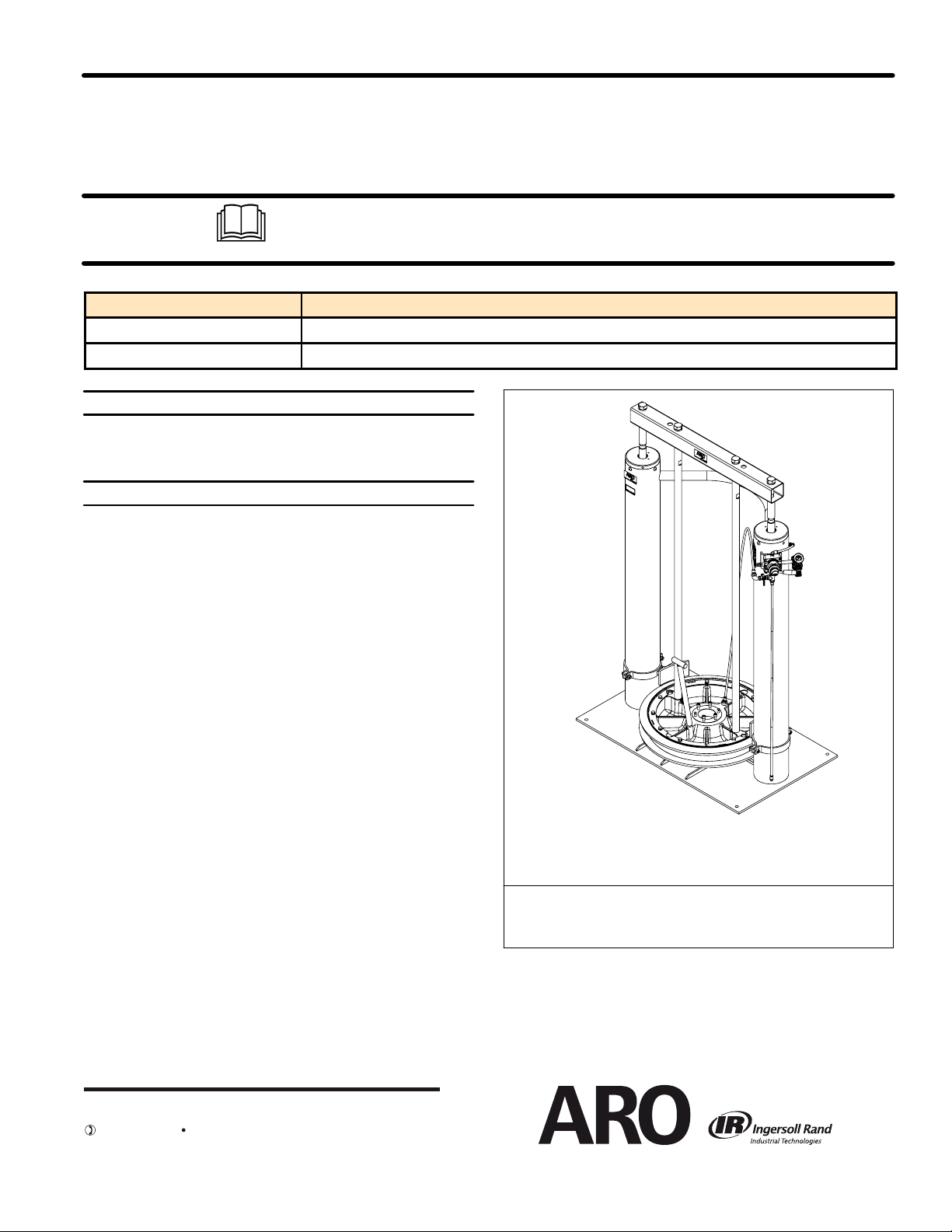
The ARO Model651612-X Two Post Lift /Ram is usedto help forcehigh
viscosity materials or greases intothe pumpmaterialinlet.This unit uses
dual 5-1/2’’ air operated cylinders welded to aheavy gauge plate and a
tubular steelcross member to raise andlower afluid handlingpump assembly into and out of a standard 55 - gallon drum.
The cast aluminum follower is fitted with a dual-lipped seal to wipe the
drum clean and seal off the material from the atmosphere. Several follower plate outer seal material options are available to be compatible
with the materialbeing pumped. Ina typical configurationthe pump lower pumpend is securely attached to the follower plate andis furtherstabilized by a support bracket assembly. Hold down brackets located on
each of the cylinders help to properly position drum with the follower
plate each time the drum is changed.
It is besttopermanently fasten the lift/ram to thefloor. Once theunit has
been properly anchored in concrete, this unit has the ability to raise a
pump 38-1/4” (toclearastandard 55 -gallondrum.)The operator isthen
able to easily remove a pump and follower assembly from a drum in order to exchange drums.
This unit usesa lever type controlvalve which controls theair necessary
toraise and lower the lift. Thistype ofvalveexhauststhroughaport in the
valve.
The lift also includes an auxiliary manualair valve which is used to supply acontrolled amountof airto thefollower plate.A smallamount ofair
supplied under the follower plate will help to raise the follower plate,
pump and lift by relieving the vacuum.
FIGURE 1
651612-X
HEAVY DUTY TWO POST LIFT/RAM
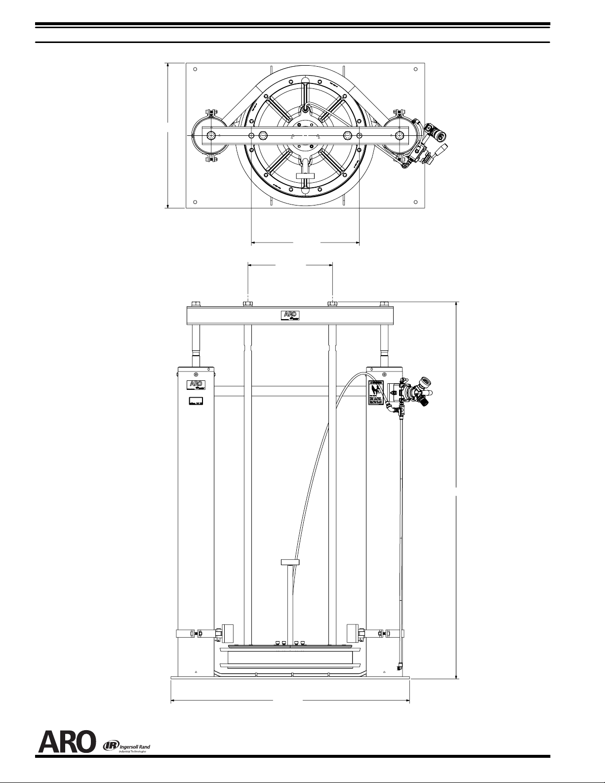
BASE DIMENSIONS: 39-1/2” (100.3 cm) x 24” (61.0 cm)
HEIGHT: LOWERED 61-3/4” (156.2 cm), RAISED: 99-13/16” (253.4 cm)
INGERSOLL RAND COMPANY LTD
209 NORTH MAIN STREET – BRYAN, OHIO 43506
(800) 495-0276
www.ingersollrandproducts.com
FAX(800) 892-6276
© 2012 CCN 81377905
Page 2
OPERATING AND SAFETY PRECAUTIONS
Z
Read andheed allWarnings, Cautions and Safety Precautions
before operating.
Z UseonlygenuineAROreplacementpartsto assure compatible
pressure rating and longest service life.
WARNING
CONCRETE. DO NOT ATTEMPT TO USE THE LIFT UNTIL ALL
POSSIBLE MEASURES HAVE BEEN TAKEN TO INSURE THAT
THE LIFT HAS BEEN PROPERLY INSTALLED AND THE BASE
IS SECURELY FASTENED. It is the duty of the installer to provide
anchor bolts / studs (not included) and for them to be securely embedded in concrete which is more than 2’’ thick. An improperly secured lift is unsafe.
WARNING
AREAABOVETHELIFTISCLEAROFELECTRICALFIXTURES,
DEVICES AND WIRING(minimum of 100” is required.)Examine
the working area and take necessary action to assure adequate
clearance for the lift and pump assembly to raise to the fullest limit
and function properly.
WARNING
OF 100 p.s.i. (6.9 bar). OPERATING LIFT AT HIGHER PRESSURE MAY CAUSE LIFT DAMAGE AND / OR PERSONALINJURY AND / OR PROPERTY DAMAGE.
WARNING
Know thepressure limitations of the drumand regulatethe air pressure within safe limits when supplying air to the follower plate.
THE LIFT MUST BE SECURELY ANCHORED IN
PREVENT ELECTRIC SHOCK. BE CERTAIN THE
DO NOT EXCEED MAXIMUM INLET PRESSURE
DO NOT EXCEED DRUM PRESSURE LIMITS.
WARNING
AND FEET CLEAR OF DRUM WHEN LIFT IS ASCENDING AND
DESCENDING. Do not attempt to reposition the pump by grasping
the follower plate. In the raising and lowering function, the air is restricted through a secondary restrictor orifice (in addition to the air
valve). In a situationwhere theliftcould get hung uporthedescentis
restricted temporarily, the lift could in some cases drop rapidly and
be hazardous. Ifthe follower platedoes not enterthe drum properly,
DO NOT ATTEMPTTO REPOSITION ITWITH YOUR HANDS;raise the lift and restart.
WARNING
THE LIFT. It is good safety practice to stay clear of a raised lift and
operate it from a safe position. When using the larger size pumps
(10” & 12”) the clearance of the air motor and cross tube are quite
close, KEEP HANDS AWAY FROM THIS AREA ANY TIME THE
PUMP IS DESCENDING.
WARNING
HOSES OR DISPENSINGVALVEWHILETHESYSTEMIS PRES-
SURIZED AS SERIOUS PERSONAL INJURY COULD RESULT.
First disconnect airline; then releivepressurefrom system byopening valve or device and / or carefully and slowly loosening and removing outlet hose or piping from the pump.
CAUTION
MENT HAVE BEEN TRAINED FOR SAFE WORKING PRACTICES, UNDERSTAND IT’S LIMITATIONS AND WEAR SAFETY
GOGGLES / EQUIPMENT WHEN REQUIRED.
AVOIDPOSSIBLE INJURY. KEEP HANDS, ARMS
STAND CLEAR WHEN RAISING OR LOWERING
DO NOT SERVICE OR CLEAN LIFT, PUMP,
BE CERTAIN ALL OPERATORS OF THIS EQUIP-
651612-XPAGE2OF8
Page 3
MODEL DESCRIPTION / FOLLOWER PLATE OPTIONS
MODEL
NUMBER
LOCATION
OF RODS
FOLLOWER
ASSEMBLY
SEAL
MATERIAL
651612 17.875” -- -- -- -- -- -- -- -- -- -- -- -- --
651612-1 14.000” 66516 Nitrile
651612-2 14.000” 66516-1 Polyurethane
651612-3 14.000” 66516-2
EPR
651612-4 17.875” 66517 Nitrile
651612-5 17.875” 66517-1 Polyurethane
651612-6 17.875” 66517-2 EPR
651612-7 17.875” 67195-2 EPR
651612-8 17.875” 67195-1 Neoprene
651612-9 17.875” 67195-3 Viton
651612-10 17.875” 67196-2 EPR
651612-11 17.875” 67196-1 Neoprene
651612-12 17.875” 67196-3 Viton
651612-59 17.875” 67195-7 = Viton
= Follower plate is PTFE coated.
GENERAL LIFT INSTALLATION INSTRUCTIONS
1. The area abovethe lift work areamust be clearand without obstructions and safely away from anything electrical.
2. THE LIFT BASE SHOULD BE SECURELY ANCHORED IN CON-
CRETE. Anchor bolts/ studs mustbeembedded in AT LE AST 2” of
good concrete is recommended. The base itself can be used for a
template for establishing the proper anchor locations.
3. Install an air shut-off valve between air source and pump air inlet.
NOTE: One of theavailableF-R-L combinations should beusedwiththe
ram. Refer to page 5.
651612-X
PAGE3OF8
Page 4
INITIAL SET-UP PROCEDURE
1. Assemble pump to follower plate.
2. Place pump on follower plate and secure with the proper fasteners.
3. Mount 91519 mountingplate to bottomof air motoronly if a 4-1/4”or
6” air motor is going to be used. Be sure support rods are properly
placed in the 14” (35.6 cm) location to mount air motor. Use the
17-7/8” (45.4 cm) support rod spacing for the 8”, 10” or 12”.
NOTE: It may be necessaryto loosen pumpspacer rods nuts in orderto
re-index the air motor on the pump to a more favorable position.
LIFT OPERATION
TO RAISE LIFT:
1. Connect air supply 100 p.s.i. (6.9 bar) to air regulator coupler (not
supplied).
2. Adjust air regulator pressure tobetween30and40 p.s.i. (2.1 and 2.8
bar).
3. Remove vent plug.
4. Rotate lift valve lever to the “UP” position to raise lift.Be certain the
lift is clear of any objects above. Also refer to “OPERATING AND
SAFETY PRECAUTIONS” found on page 2.
5. Raise the lift to desired height to clear drum. Stop lift upward travel
by rotating lift valve lever to the “NEUTRAL” position.
TO LOWER LIFT:
SAFETY NOTE:The liftmay hesitatebefore startingdownward, theair
pressure inside the lift post air chamber must decrease before it will begin to descend.
4. Place two supportbrackets around base ofthe air motorand secure
with four Y6-65-C 1” long screws, four Y16-616 lockwashers and
four Y12-6-C jam nuts.
5. Install an air shut-off valve between air source and pump.
NOTE: This is important for pump control when the pump and follower
are in the “UP” position.
TO CHANGE DRUMS:
CAUTION
TIONS OF DRUM AS INDICATED BY DRUM SUPPLIER /
MANUFACTURER.
1. Disconnect air supply to pump.
2. When utilizing thefollower air valveassistfeature; open thefollower
plate air supplyvalvesupply an amount ofair sufficient to helpthelift
raise the pump through the material drum.
3. SLOWLYrotate lift valvelever to “UP” position andraise lift bythrottling the lift valve.
4. When the follower plate air supply is no longer needed; turn off air
valve and remove vent plug.
5. Replace drum.
6. Repeat steps under “TO LOWER LIFT” section.
DO NOT EXCEEDMAXIMUM PRESSURE LIMITA-
NOTE: The lift valve should be in the “NEUTRAL” position.
1. Place the drumin position securelyagainst barrel guidesand adjust
if needed.
2. Align pump and follower with drum.
3. Turn lift valve lever to the “DOWN” position to begin lowering.
WARNING
CLEAR OF ASCENDING AND DESCENDING LIFT.Referto“OPERATING AND SAFETY PRECAUTIONS” on page 2.
4. Gradually work the follower seal into the drum, be certain the vent
plug has been remove (as applicable) so that the air trapped between the follower and the material is allowed to escape.
5. Air trapped between material and follower will purge through the
vent plug opening. Whenmaterial“oozes” from the vent,replacethe
vent plug. Thelift valve levershould remain inthe “DOWN” position.
6. At thispoint the pump should be started and allowed to prime. After
the pump has cycled several times, all the trapped air should be
purged from the pump, hose assembly, and the extrusion gun. A
steady stream of material from the nozzle indicates the system is
primed andready tooperate. Pump should stall out or remain static
when extrusion gun is in the “OFF” position.
7. Should pump continue to cycle after extrusion gun is in the “OFF”
position, increase theair pressure tothe lift valvetoa higher setting;
this increases the forceexertedbythe two cylinders and thefollower
plate on the material.
8. If this does not remedy the problem; increase the setting in increments of 10 p.s.i. (0.7 bar) up to 90 p.s.i. (6.2 bar) or purge the
trapped air under the follower plate or in the system.
BE CERTAIN HEAD, HANDS AND ARMS ARE
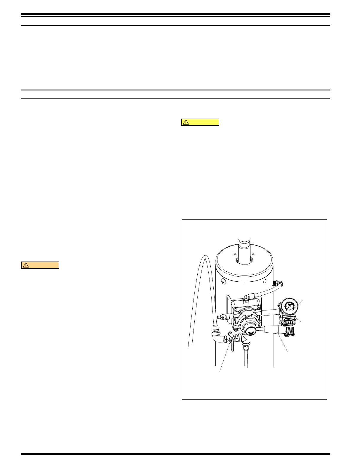
AIR CONTROLS
Gauge
Regulator
Control Lever
Follower Plate
Air Supply Valve
Figure 2
651612-XPAGE4OF8
Page 5
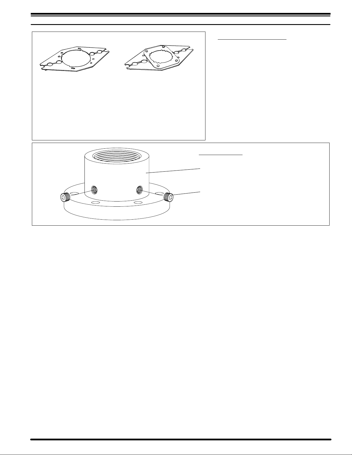
OPTIONAL EQUIPMENT
Pump Stabilizing Bracket Kit (includes hardware)
66353-1 for 8”,10”,12” Motors
Includes:
92362 Support Bracket (2)
Y6-65-C Screw (4)
Y6-66-C Screw (4) (3/8” -16x 1-1/4”)
Y12-106-C Jam Nut (4) (3/8” - 16)
Y12-6-C Nut (4) (3/8” - 16)
Y14-616 Lockwasher (8) (3/8”)
(3/8” -16x 1”)
66354-1 for 4-1/4”,6” Motors
Includes:
91519 Mounting Plate
92362 Support Bracket (2)
Y6-62-C Screw (4)
(3/8” -16x 5/8”)
Y6-65-C Screw (4) (3/8” -16x 1”)
Y6-66-C Screw (4) (3/8” -16x 1-1/4”)
Y12-106-C Jam Nut (8) (3/8” - 16)
Y12-6-C Nut (4) (3/8” - 16)
Y14-616 Lockwasher (12) (3/8”)
H Filter-Regulator-Lubricators
4-1/4”,6-1/4” - 65940 HD FRL w /Bracket
8”,10”,12” - 651729 HD FRL w /Bracket
H Polyethylene Follower Plate seal
protector sheets (included)
91363-10 Pkg of 10 - 32” dia. (55 gal. drum)
67136 Adapter Kit
67136 Adapter Kit Assembly
Y17-50-S Pipe Plug (2) ~
FIGURE 3
~ Included in 67136 Adapter Kit Assembly.
651612-X
PAGE5OF8
Page 6
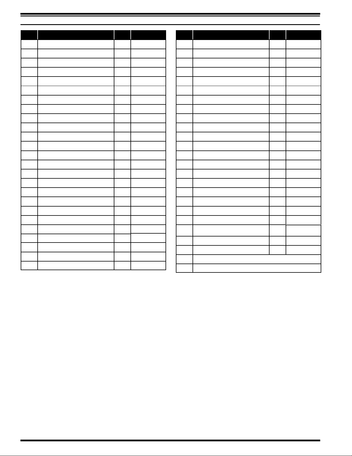
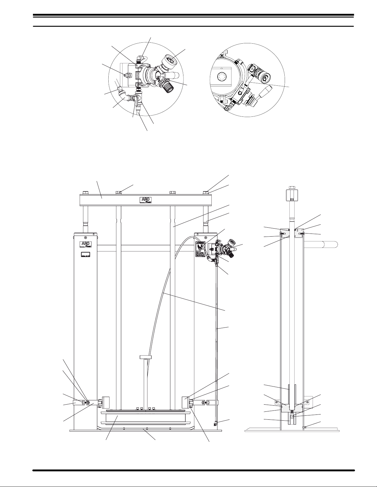
PARTS LIST
ITEM DESCRIPTION (Size in inches) (Qty) Part No. ITEM DESCRIPTION (Size in inches) (Qty) Part No.
n 1 Retaining Ring (1.942” o.d.) (2) Y147-175
2 Guide (2) 97182
3 Screw (3/8” -16x 5/8”) (8) Y211- 164
n 4 “O” Ring (1/8”x1-1/2” o.d.) (2) Y325- 218
5 Lock Washer, Hi-Collar (1/2”) (2) Y79-816
6 Screw (1/2” -13x 2-1/2”) (2) Y99-88
7 Drain Cock (1/8 - 27 N.P.T.) (2) Y57- 1
8 Stop Tube (2) 97183
n 9 Wear Strip (2) 97184
n 10 “O” Ring (1/4”x5-1/2” o.d.) (4) Y325-429
11 Piston (2) 97185
12 Stop Tube (2) 97186
n 13 “O” Ring (3/16”x1-5/8” o.d.) (2) Y325-322
n 14 Rod Scraper (2) 97187
15 Screw (7/8” -9x 4-1/2”) (2) 97188
16 Lock Washer (7/8”) (2) Y14-875
17 Vertical Support Rod (2) 94016
18 Piston Rod (2) 97189
19 Decal (Warning) (1) 93922
20 4-Way Air Valve (1) M512LR
21 Adapter (1/4” N .P. T. F.) (1) 1950
V 23 Tubing (5/16” o.d. x 60”) (1) 94980-XXX-X
f 24 Tubing (3/8” o.d. x 42-3/4”) (1) 94980- XXX
25 Clamp Shoe (2) 97190
26 Clamp Pin (2) 97191
27 90_ Male Elbow (1/4 N.P.T. x 3/8”) (3) 59756-158
28 Hair Pin Cotter (2) 97192
29 Welded Assembly (1) 67444
30 Follower Assembly (See page 3)
31 Clevis Bracket (2) 95354
32 Clamp Bracket (2) 95353
33 Screw (3/8” -16x 1-1/2”) (4) Y99-64
34 Nut (3/8” - 16) (4) Y12-6-C
35 Lock Washer (3/8”) (4) Y14-616-C
36 Cross Bar (1) 97193
37 Screw (7/8” - 14 UNF x 4”) (2) 94009
f 38 Tubing (3/8” o.d. x 6”) (1) 94980-XXX
39 Gauge (0 - 160 p.s.i. / 0 - 11 bar) (1) 104493
40 Regulator g (1) R37121-100
41 Tee (1/4 - 18 N.P.T.) (1) Y43-32- C
42 Shut-Off Valve (1/4 - 18 N.P.T.) (1) Y28-1
43 90_ Street Elbow (1/4 - 18 N.P.T.) (1) Y43-2-C
44 Male Connector (1/4 N.P.T. x 5/16”) (2) 59474-158
45 Silencer (1/4 - 18 N.P.T.) (1) 20313-2
46 Screw (1/4” -20x 1 1/4") (2) Y99-43
48
Pipe Nipple (1/4 N.P.T. x 2 1/2”) (1) Y44-12-C
Service Kit 637343
g Service Kit for Regulator 104158
f Bulk Tubing (3/8” o.d. x 100’)
V Bulk Tubing (5/16” o.d. x 100’)
DISASSEMBLY
1. Remove (37) screws, releasing (17) vertical support rods from the
(36) cross bar.
2. Remove(15) screws and (16) lock washers, releasing(36) crossbar
from the (18) piston rods.
3. Remove (1)retaining ringand (14)rod scraper from the top of each
(2) guide.
4. Remove (3) screws, releasing (2) guides from the (29) weldment
tubes sliding over the piston rods.
5. Remove (10) “O” rings from the o.d. of (2) guides.
6. Remove (13) “O” rings from the i.d. of (2) guides.
7. Remove (11)pistonand(18) rod assembly from each (29)weldment
tube and remove (9) wear strip from each (11) piston.
8. Remove (6) screw and (5) lock washer, releasing (8) stop tube and
(11) piston assembly from the (18) piston rod.
9. Slide (12) stop tube from each (18) piston rod.
10. Remove (10) “O” rings from the o.d. of (11) pistons.
11. Remove (4) “O” rings from the to i.d. of (11) pistons.
REASSEMBLY
1. Grease (4) “O” rings and assemble to i.d. of (11) pistons.
2. Grease (10) “O” rings and assemble to o.d. of (11) pistons.
3. Slide (12) stop tube over each (18) piston rod.
4. Assemble (11) piston assembly to (18) piston rod using (8) stop
tube, (5) lock washer and (6) screw on each (18) piston rod.
5. Apply oil to both (29) weldment tubes.
6. Assemble(9) wear strip to each (11) pistonandinsert(11) piston and
rod assembly into each (29) weldment tube.
7. Grease (13) “O” rings and assemble to i.d. of (2) guides.
8. Grease (10) “O” rings and assemble to o.d. of (2) guides.
9. Assemble (2) guides to (29) weldment tubes sliding over the piston
rods and secure with (3) screws. Note: Small tapped holes in topof
(2) guide must be oriented to cross-over tube of (29) weldment.
10. Assemble (14) rod scraper and (1) retaining ring to the top of each
(2) guide.
11. Position (36) cross barover(18)piston rod andsecurewith(16) lock
washer and (15) screw in each (18) piston rod with impact wrench.
12. Assemble (17) vertical support rods to (30) follower assembly and
assemble unit to lift with (37) screws and tighten.
651612-XPAGE6OF8
Page 7
45
46
PARTS LIST
27
39
36
44
43
42
41
38
VALVE DETAIL
37
40
19
15
16
17
18
21
20
14
10
13
48
1
2
3
34
35
33
32
31
30
29
28
23
44
24
25
26
27
12
11
10
4
5
9
8
6
7
651612-X
FIGURE 4
PAGE7OF8
Page 8
(24.000”)
DIMENSIONAL DATA
(17.875”)
(14.000”)
(39.500”)
(62.410”)
FIGURE 5
PN 97999-226
651612-XPAGE8OF8
 Loading...