

Page 1

1995-1996
Lincoln Continental
Front Air Spring Installation
Manual
INSTALLATION:
Congratulations on your recent purchase of the
Arnott 95-Top® replacement air spring for the 19951996 Lincoln Continental. This air spring provides
proper vehicle handling and performance, in
accordance with the manufacturers specifications.
As with all products requiring assembly, proper
installation is essential in order to appreciate and
benefit from the products capabilities. Please take a
moment to review the instruction manual in order to
familiarize your self with the product’s components.
Please be aware of, and take all applicable safety
measures while installing your new air spring. The
illustrations and instructions within this manual are all
of the right side (passenger’s side) of the vehicle.
Installation of the left side assembly will follow the
same instructions. Any exceptions will be highlighted
and noted in bold text.
Parts List:
Air Spring Assembly 95-TOP 1 # 114 O-Ring 1
# 015 O-Ring 2 # 141 O-Ring 2
#23 x 4mm O-ring 1
WARNING!
Do not inflate the air spring assembly while it is
unrestricted. The air spring assembly must be
restricted by the suspension system or another
adequate structure. Do not inflate the air spring
beyond 100 psi. Over inflation of the air spring, as
well as improper use of the assembly, may cause
severe personal injury or property damage.
Please do not exceed the maximum load
recommended by the vehicle manufacturer. (GVWR)
While the sir springs are rated by the manufacturer to
have a maximum pressure of 100 psi, this pressure
may allow too great a load to be carried on most
vehicles. For best results, load the vehicle and have it
weighed, then compare the vehicle weight with the
maximum allowed. Your vehicle owner’s manual or
data plate located on the inside of the driver’s door
will have the maximum loads listed. It is suggested
that all recommendations be followed for your own
safety and for the safety of the vehicle.
Page 2
Page 3

WARNING: Do not remove shock absorber's
flanged center nut while there is air pressure
remaining in the air spring. Failure to do so will
result in the unexpected separation of the shock/air
spring components.
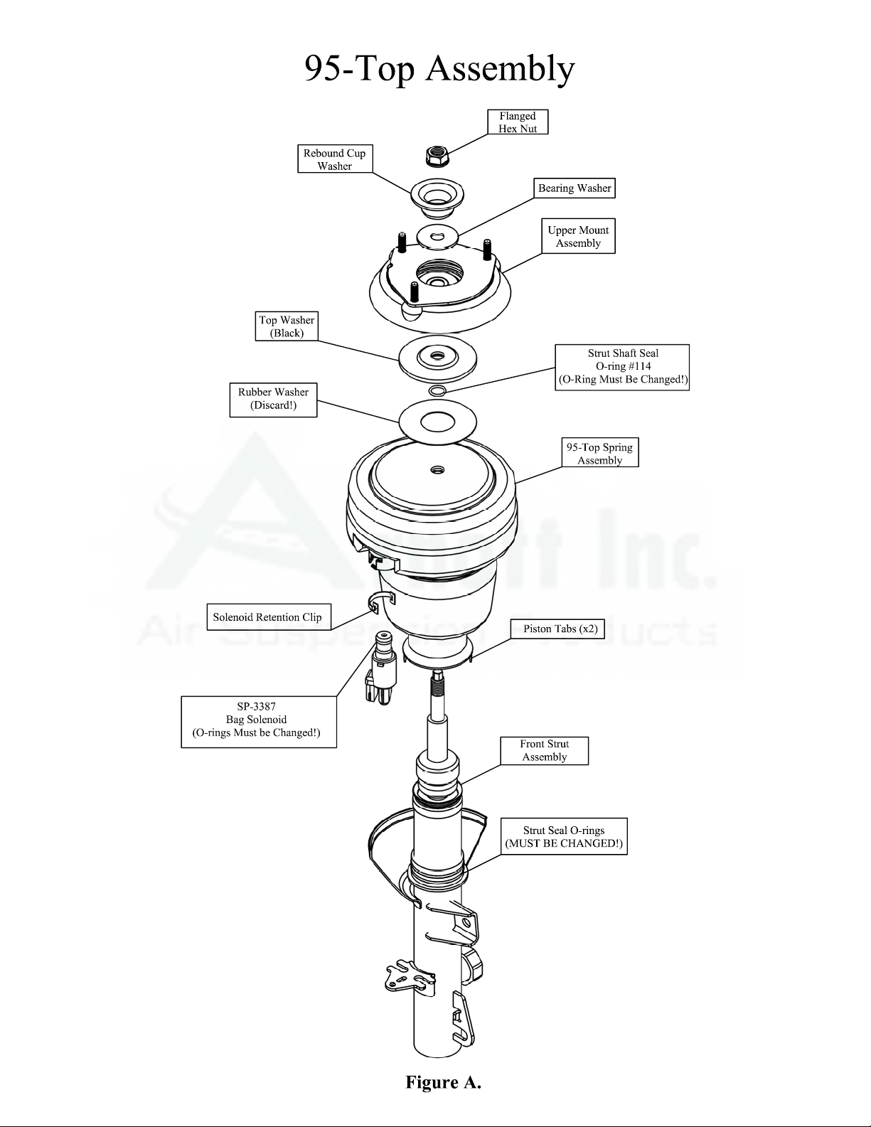
Step #1: Disassembly of the shock/air spring
a. Remove the large Flanged Hex nut located at the top of
the Strut Assembly
b. Remove the rebound cup & bearing washer
c. Remove the upper mount assembly
d. Remove the black top washer.
e. Remove the rubber washer and discard
(This will not be used with the new assembly)
f. Press out on the two plastic retaining clips (Figure B)
g. Gently pry the air spring piston apart from the strut
using a flat head screwdriver on the piston bottom.
(Figure C.)
h. Remove the air spring from the strut
i.
Change the 2 large O-rings located on the strut.
(Failure to change o-rings will cause strut to
leak!)
Step #2: Reassembly of the shock/air spring
a. Place the new air spring (Part # 95-TOP) onto the strut.
b. Place the new o-ring #114 onto the
c. Replace the black top washer with the c
facing down toward the o-ring
d. Replace the upper mount assembly.
e. Replace the rebound cup & bearing was
f. Tighten the flanged center nut. (63-71 l
g. Assembled Strut should appear as Figur
Note: Refer to Figure A for the placem on of all
above procedures and components.
strut shaft.
hamfered side
her.
b-ft.)
e D.
ent and descripti
Page 4

Page 5

95-96 Continental Front Air Strut
Removal and Installation.
Step #1: Strut Removal
a. Tu rn the air suspension switch to the off position. (switch is located on the driver’s side of the
trunk)
b. Raise the vehicle with proper lifting equipment. Tires must be off of the ground with the
suspension down and under no load. ALWAYS USE EXTREME CAUTION WHEN LIFTING
VEHICLE! (Refer to shop manual for lifting instructions)
c. Remove wheel
d. Remove the solenoid retaining clip using a flat head screwdriver.
e. Rotate the solenoid counterclockwise to the first stop, and then pull down on the solenoid to
release the air in the air spring. Make sure all of the air vents out of the air spring! Rotate again
and remove the solenoid.
f. Unbolt the brake line and remove from mounting bracket. Also unplug the strut electrical damper
solenoid.
g. Remove the ABS sensor cable from the strut.
h. Unhook the height sensor from its bottom mount.
i. Remove the lower knuckle pinch bolt and nut.
j. Remove stabilizer bar link nut.
k. Remove stabilizer bar link from strut
l. Loosen the top three mount to shock nuts. DO NOT REMOVE THE LARGE CENTER NUT!
m. Carefully remove the old air spring/shock assembly from the vehicle.
Note: Refer to Figure E for the placement and description of all above procedures and components.
Step #2: Disassembly & Reassembly of the shock/air spring
a. All procedures are outlined in detail in the above section
Step #3: Strut Installation
a. Install the new air spring/shock assembly and three upper mount-to-shock nuts. Do not tighten
nuts!
b. Install knuckle pinch bolt and nut. (Tighten to 73-79 lb-ft.) (Reverse Step 1:i)
c. Ch ange solenoid o-rings supplied with new air spring. Install solenoid in the new air spring.
(Reverse Step 1:d,e)
d. Install stabilizer bar link and tighten nut to 57-75 lb-ft. (Reverse Step 1:j,k)
e. Install Brake line to mounting bracket. (Reverse Step 1:f)
f. Install ABS cable back onto strut mounting bracket. (reverse Step 1:g)
g. Snap height sensor bottom back onto its lower ball stud (Reverse Step 1:h)
h. Replace wheel and lower suspension.
i. Turn air suspension switch back to the on position and start the vehicle. Suspension will
automatically lift back to its normal trim height.
Note: Refer to Figure E for the placement and description of all above procedures and components.
 Loading...