

Armstrong Pumps H-32, H-41, H-51, H-52, H-53 User Manual
...
FILE NO: 10.51
DATE: July 25, 2012
SUPERSEDES: 10.51
DATE: June 14, 2011
STANDARD CIRCULATORS Series “H”
JOB:
ENGINEER:
CONTRACTOR:
PUMP DESIGN DATA
Pump Model: Flange Size:
No. of Pumps:
Note:
Capacity: USgpm (I/s) Temperature: ºF (ºC)
Head: ft. (m) Liquid:
Companion Flanges Included
REPRESENTATIVE:
ORDER NO:
SUBMITTED BY:
APPROVED BY:
Maximum Working Pressure: 125 Psig 863 (kPa)
Maximum Operating Temperature: 225 ºF (107 ºC)
OPTIONAL EQUIPMENT
Performance curve See pg. 2
SUBMITTAL
DATE:
DATE:
DATE:
MATERIALS OF CONSTRUCTION
PUMP NAME
Pump Body Cast Iron Bronze / Lead Free Bronze
Impeller Non-Ferrous
Bearings Sleeve-Oil Lubricated
Shaft Alloy Steel-Copper Sleeve
Seal Mechanical
Stationary Seal Face
Coupler
* Contains less than 0.25% lead, weighted average
H-32 & H-41 Flexible, 4-Spring
H-51 to H-54 Flexible, Spacer Type H-51 to H-54 Flexible, Spacer Type
H-32 to H-54
(BRONZE Fitted)
H-63 to H-68
(BRONZE Fitted)
Flexible, Spacer Type
H-32 to H-54
(ALL BRONZE / LF-BRONZE*)
Sintered Silicon Carbide
H-32 & H-41 Flexible, 4-Spring
H-63 to H-68
(ALL BRONZE / LF-BRONZE*)
Flexible, Spacer Type
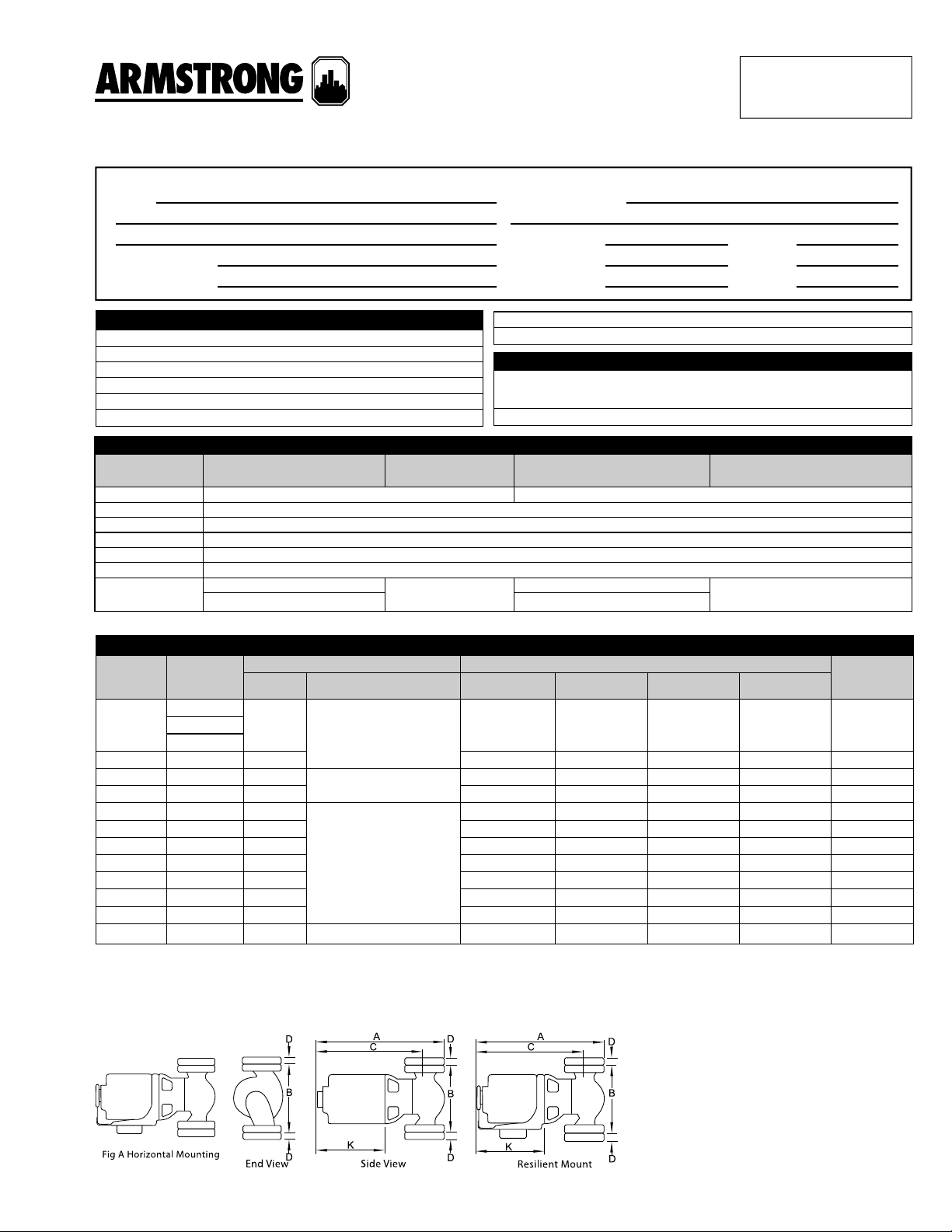
DIMENSIONAL DATA
MODEL
H-32
H-41 1 1/6 15-1/4 (387) 8-1/2 (216) 12-1/2 (318) 3/4 (19) 33 (15.0)
H-51 1 1/4 17-1/4 (438) 11-1/2 (292) 13-1/2 (343) 3/4 (19) 53 (24.0)
H-52 1-1/4 1/3 17-1/4 (438) 11-1/2 (292) 13-1/2 (343) 7/8 (22) 54 (24.0)
H-53 1-1/2 1/2
H-54 2 3/4 20 (508) 11-1/2 (292) 16-1/2 (419) 7/8 (22) 71 (32.0)
H-63 1-1/2 1/2 23 (584) 13- 1/2 (343) 19-3/4 (502) 7/8 (22) 96 (44.0)
H-64 1-1/2 3/4 23 (584) 13- 1/2 (343) 19-3/4 (502) 7/8 (22) 100 (45.0)
H-65 1-1/2 1 23 (584) 13-1/2 (343) 19-3/4 (502) 7/8 (22) 102 (46.0)
H-66 2 3/4 23-1/4 (591) 14 (356) 19-3/4 (502) 7/8 (22) 120 (54.0)
H-67 2 1 23-1/4 (591) 14 (356) 19-3/4 (502) 7/8 (22) 125 (57.0)
H-68 2 1-1/2 3 Phase 208/230/460or 575 V 21-3/4 (552) 14 (356) 18-1/4 (464) 7/8 (22) 130 (59.0)
FLANGE
SIZE
(N.P.T.)
1
1-1/2
H.P. PHASE & VOLT A B C D
1/6
MOTOR** DIMENSIONS Inches (mm)
1 Phase 115 V
1 Phase 115 V or
3 Phase 208/230/460V
1 Phase 115/230 V
or 3 Phase 208/230/460
or 575 V
15 (381) 8-1/2 (216) 12-1/2 (318) 7/8 (22) 33 (15.0) 1-1/4
20 (508) 11-1/2 (292) 16-1/2 (419) 7/8 (22) 64 (29.0)
WEIGHT lbs
Dimensions shown are for reference only.
**All single phase motors are equipped with built-in thermal overload protection.
Three phase motors require external overload protection.
Conduit box not supplied on ½ hp or greater.
SHIPPING
(kg)
Page 1 of 2
Page 1 of 2

PERFORMANCE CURVES
Performance Guaranteed Only At Operating Point Indicated
S. A. Armstrong Limited
23 Bertrand Avenue
Toronto, Ontario
Canada, M1L 2P3
T: 416-755-2291
F: 416-759-9101
For Armstrong locations worldwide, please visit www.armstrongintegrated.com
Armstrong Pumps Inc.
93 East Avenue
North Tonawanda, New York
U.S.A. 14120-6594
T: 716-693-8813
F: 716-693-8970
Armstrong Integrated Limited
Wenlock Way
Manchester
United Kingdom, M12 5JL
T: +44 (0) 8444 145 145
F: +44 (0) 8444 145 146
Page 2 of 2
© S.A. Armstrong Limited 2011
 Loading...