

Armstrong Pumps astro 210ci, astro 210ss, astro 220ssu, astro 225ssu, astro 225bs User Guide
...Page 1
Installation
and operating
instructions
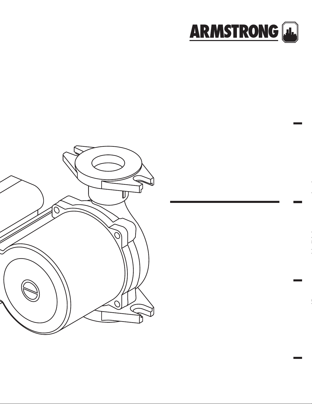
Astro 2 circulator
models
File No: 10.89
Date: ju ly 20, 2016
Supersedes: 10.89
Date: august 05, 2013
Page 2

Page 3

contents
1.0 Introduction 4
2.0 Installing 4
2.1 Terminal box 4
2.2 Electrical wiring 5
3.0 Check valve removal (optional) 5
4.0 Start up 5
5.0 Installation troubleshooting guide 6
6.0 Spare parts 7
Page 4
installation &
operating instructions
4
Astro 2
circulator models
warning
• Prior to installation, read these installation and
operating instructions. Installation and
operation must comply with local regulations and
accepted codes of good practice.
• The use of this product requires experience with and knowledge of the product. Only licensed or trained installers
should install this product.
• For supply connection, use wires acceptable for at least
90°c (194°f).
• Risk of shock: this pump has not been tested for use in
swimming pools or marine areas.
• To reduce risk of electric shock: Unplug before servicing,
see instructions for proper installation, connect to a properly grounded, grounding type receptacle only.
• For indoor use only.
• Use copper conductors only.
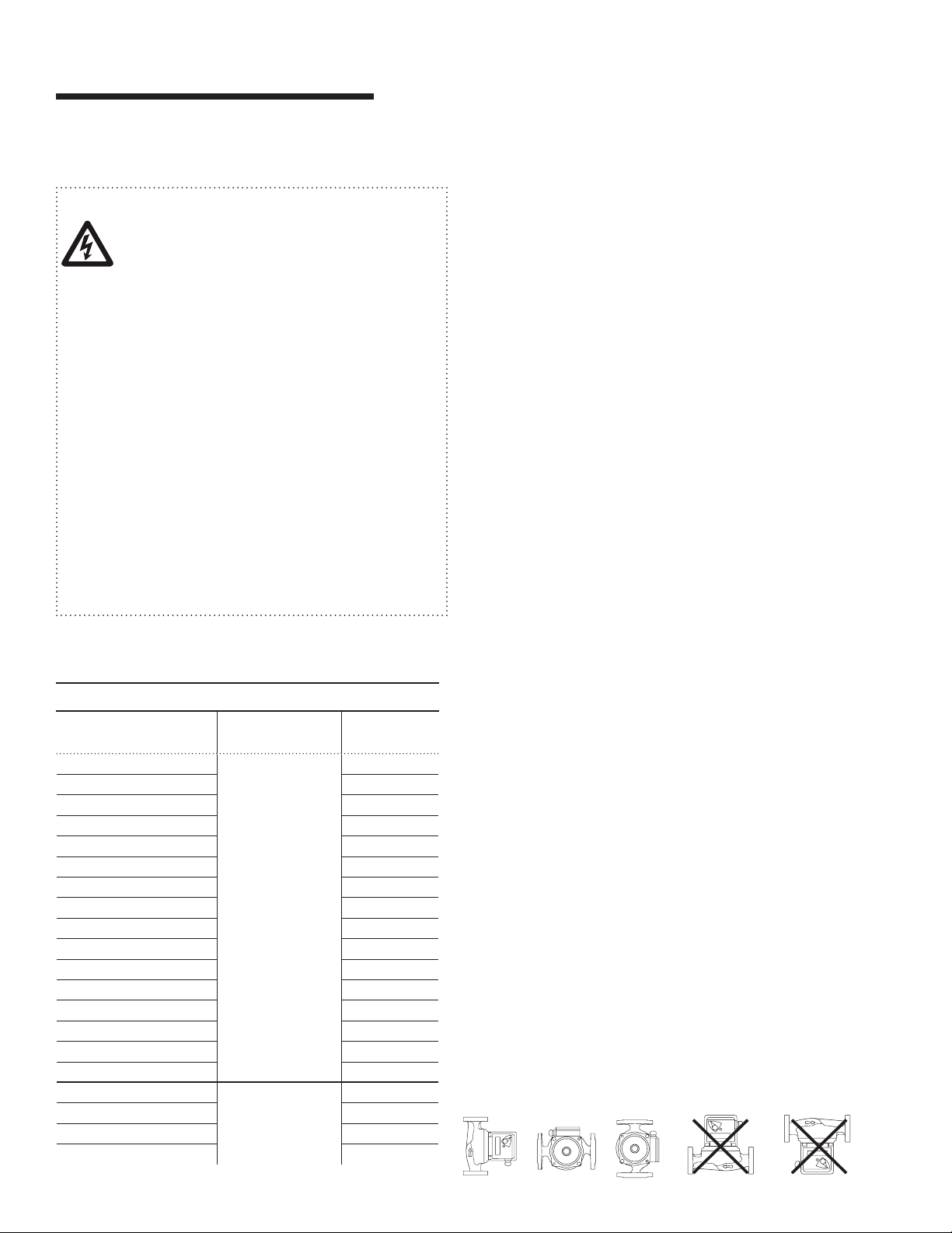
• Do not install with motor above or below pump body.
• Do no submerge.
• Do not run pump dry.
These installation and operating instructions are applicable to the
following Astro 2 models.
1.0 introduction
You are about to install a pump from the finest multi-speed wet
rotor circulator line on the market today. The Armstrong Astro
2 circulators are designed for closed hydronic or potable water
systems. Their intended use is for circulating water or glycol
solutions. For pumping domestic water use non-ferrous lead
free bronze or stainless steel body pump construction.
The Astro 2 operates extremely quietly and is lubricated by the
system liquid being pumped by the circulator.
These circulators except Astro 286 are designed to work at
temperatures and pressures up to 230°f (110°c) and 150 psi.
Astro 286 is designed to work at temperature and pressure
upto 150°f (65°c) and 150psi. For fluid temperature upto 185°f
(85°c), operating current must not exceed 1.35a. For lead free
bronze and stainless steel pumps used in potable water systems, it is recommended that the operating temperature of the
fluid be kept as low as possible (i.e. below 150°f/65°c) to avoid
precipitation of calcium.
When unpacking the circulator, inspect for any damage that
may have occurred during transit. Check for loose, missing or
damaged parts.
astro 2 models
model
astro 210ci
astro 210ss 200w, 1.72a
astro 220ssu 33w, 0.29a
astro 225ssu 83w, 0.69a
astro 225bs ½" swt 75w, 0.64a
astro 225bs O" swt 75w, 0.64a
astro 230ss 97w, 0.81a
astro 230ci 97w, 0.81a
astro 230ci-r 97w, 0.81a
astro 250ss 117w, 0.98a
astro 250ci 117w, 0.98a
astro 250ci-r 117w, 0.98a
astro 280ci 218w, 1.9a
astro 280ss 218w, 1.9a
astro 290ci 218w, 1.9a
astro 290ss 218w, 1.9a
astro 280ci 230v
astro 280ss 230v 210w, 0.9a
astro 286ci 370w, 1.6a
astro 286ss 370w, 1.6a
electrical
input
115v, 60hz
Single phase
23 0v, 60hz
Single phase
rating
200w, 1.72a
210w, 0.9a
2.0 installing
We recommend that any soldering be done before the pump
is actually installed. This will eliminate the possibility of solder
dropping into the pump body.
Thoroughly flush the system out before installing the circulator.
Before Installing, check that the flow direction of the water
through the pump body matches the arrow on the circulator
body. The circulator is supplied for up discharge installation.
Install the circulator in either the outlet or inlet line to the boiler
or hot water heater. It is important to install these circulators
with the split between the circulator body and the motor in a
vertical position. This ensures ecient operation.
See installation examples.
incorrect installationscorrect installations
Page 5
Astro 2
plug
1
2
3
circulator models
installation &
operating instructions
5
The circulator shaft must always be in a horizontal position.
(The piping can be in a horizontal or vertical run.) Isolation
valves should be installed on the discharge and suction side of
the pump to facilitate service.
2.1 terminal box
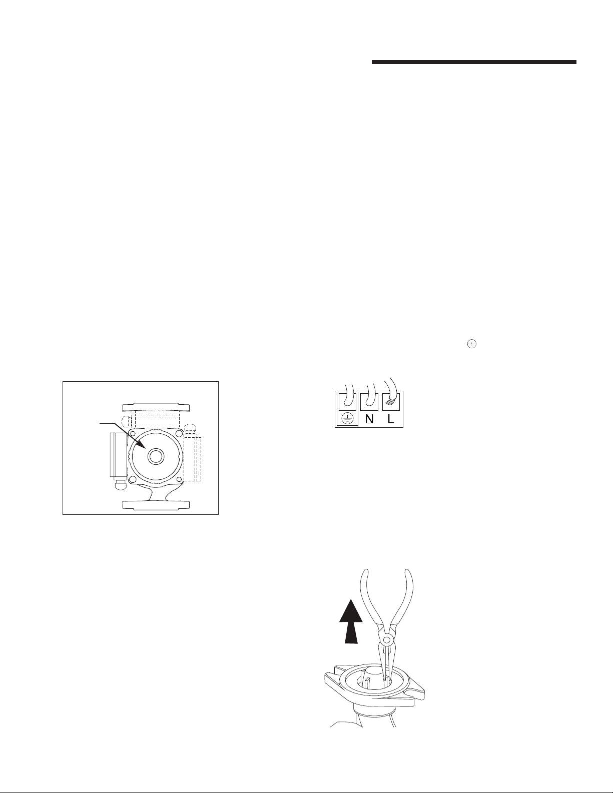
Always install the circulator with the terminal box above or beside the motor. If the terminal box is under the motor as initially
mounted, remove the motor mounting screws and rotate the
motor to the proper position. (See example.)
Ensure the gasket is intact and seated before evenly retightening the mounting screw to 4.5 - 5.5 lb/ft (6 - 7.5 Nm). To ensure
the rotor still spins freely, temporarily remove the plug (located
in the middle of the nameplate), insert a flat head screwdriver
into the slot in the end of the rotor shaft and turn.
Retighten the plug to 1.5 - 2 lb/ft (2 -2.7 Nm). Ensure no water
leak at all sealing contacts.
Wire shall be 14 to 16 gauge solid wire or 16 to 18 gauge
stranded wire.
To wire, loosen the screws from the terminal box cover and
remove the screws and cover.
Install constractors choice of strain relief into ½" npt threaded
access kit (not provided).
Insert wires through the strain relief connector and into the
terminal box.
Strip ³/af" of insulation from the ends of the three wires to
be connected.
To insert the wires into the terminal strip, press down firmly on
the terminal lever. Insert the stripped wire into the opening and
release the lever. Tug on the wire gently to ensure it is secured.
Connect the hot wire to terminal 'l', the neutral wire to terminal
'n', and the ground wire to terminal f.
Tighten the terminal box cover.
Do not hang items or articles of clothing on the pump as air
must be able to circulate freely through the motor. Do not
operate the circulator without the motor plug installed.
2.2 electrical wiring
The electrical wiring must be installed strictly in accordance
with national electrical codes, local codes and regulations.
Electrical installation should be conducted by a
1
qualified electrician.
Always make sure electric power is disconnected before
2
wiring the circulator.
The motor is designed for 60 Hz, 1 phase, 115 or 230 volt power.
The motor is thermally protected so overload protection is not
necessary. All that is required is a fused plug or circuit breaker
in the power line. Electrical information can be found on the
nameplate of the motor.
3.0 check valve removal (optional)
Using a pair of needle-nose pliers, grip one of the flat wings of
the check valve and gently pull the valve out vertically.
Page 6

installation &
operating instructions
6
Astro 2
circulator models
4.0 start up
These circulators are maintenance free. Self-lubricated by the
system fluid, these circulators have no seal to leak or coupling
to break.
A proper installation practice recommends to thoroughly flush
the system clean of all foreign materials prior to installing
the circulator.
Fill the system before starting.
Speed setting of Astro 2 3-speed circulators:
(Not applicable for Astro 286)
The speed of these pumps can be adjusted with a 3-speed
rotary switch. On speed setting 1, the pump operates at
approximately half the performance of the speed setting 3
(maximum speed) and consumes about half the power of full
speed operation.
warning
Never operate the circulator dry as permanent damage may
occur. Never shut o the discharge or restrict suction flow
while the circulator is operating.
The venting of the rotor chamber may be done automatically.
However, to assure proper and faster venting of this circulator,
we recommend the manual venting procedure as follows
Place a container under the back of the circulator to catch
1
any water that may run out.
Be sure power to the circulator is o at the fuse or
2
circuit breaker.
Loosen plug on the back of the motor but do not remove.
3
Continue until water appears.
4
After a sucient amount of water free of air bubbles has
5
passed, retighten the plug.
The circulator can now be started.
6
liquid temperature minimum inlet pressure
150°f (65°c) 3.0 ft (0.91 m )
167°f (75°c) 4.4 ft (1.34 m)
194°f (90°c) 9.2 ft (2.8 m)
230°f (110°c) 36.1 ft (11.0 m)
5.0 installation troubleshooting guide
fau lt possible cause remedy
Noise from radiator Excessive pressure passing the thermostatic valve.
The thermostatic valve is jammed or blocked.
The radiator is not
giving o any heat
The heating system is not balanced.
Incorrect discharge direction.
Dirty impeller
Pump generates
little or no output
Suction port blocked
Outlet blocked
Isolation valve closed
Dirty strainer
Air in the pump
Pump at lowest/medium speed level
Pump set point is too low
• Reduce the speed setting. Flow decreases will reduce
system pressure and eliminate the noise.
• Shut o all other radiators in the system, and set the
pump at maximum speed.
• Once the blockage has been dislodged reopen the
radiators and adjust pump to original speed setting.
• Re-assess the system. Fit new commissioning valves
on all radiators (may be integrated in the thermostatic
valves) to enable an even distribution of the flow.
• Turn pump 180°
• Open pump and clean impeller
note: Close isolation valves if present
• Open pump and clean housing
note: Close isolation valves if present
• Clean isolation valves
• Open isolation valves
• Clean strainer
• Switch o pump and open bleed screw to vent.
• Set pump to the next higher speed level.
• Increase set point on the pump or controller.
Page 7

fau lt possible cause remedy
Astro 2
circulator models
installation &
operating instructions
7
Pump stopped,
Power supply interrupted
no power
Fuse tripped or circuit breaker opened
Pump stopped, power
Thermal switch has actuated
supply present
Pump does not start
Noises in system, ther-
Pump output too high
mostatic valves/pipes
Noisy pump Air in pump
Cavitation sounds
Resonance noises
• Check the power supply. Attach external power control
if necessary.
• Repair short-circuited wire. Repair loose contact.
• Check for the properly rated fuse.
• Check pump motor and lead.
• Reduce ambient temperature.
• Clean blocked or slow rotating pumps.
• Open air vent screw and unlock shaft. Clean pump.
• Increase speed/set point.
• Replace pump.
• Reduce speed level.
• Open bypass/valve.
• Install circuit balancing valves to adjust flow.
• Check pump selection/system. Adjust pump. Check
system /gauges.
• Replace pump.
• Open bleed screw and vent pump. Vent and top up
system with water.
• Check expansion tank.
• Install air separator.
• Increase inlet pressure.
• Reduce temperature.
• Throttle back pump.
• Reduce speed.
• Use sound insulation material between the pump
and surface to reduce resonance noise. Install
expansion joints. Install fixture to change system’s
natural frequency.
• Adjusts pump speed.
• Replace pump/motor.
Knocking from foreign bodies in the
pump/or on valve
6.0 spare parts
spare part item no. applicable models
Check valve 1" 810223-104
Check valve 1¼" 810223-105
Astro 220ssu, Astro 225ssu
Astro 210, Astro 230, Astro 250, Astro 280, Astro 286
• Clean impeller.
• Adjust valve pressure. Adjust valve spring.
• Turn valve around if installed incorrectly.
• Replace pump.
Page 8

toronto
23 bertrand avenue
toronto, ontario
canada
m1l 2p3
+1 416 755 2291
buffalo
93 east avenue
north tonawanda, new york
u.s.a.
14120-6594
+1 716 693 8813
birmingham
heywood wharf, mucklow hill
halesowen, west midlands
united kingdom
b62 8dj
+44 (0) 84 44 145 145
manchester
wolverton street
manchester
united kingdom
m11 2et
+44 (0) 84 44 145 145
bangalore
#59, first floor, 3rd main
margosa road, malleswaram
bangalore, india
560 003
+91 (0) 80 4906 3555
shanghai
no. 1619 hu hang road, xi du township
feng xian district, shanghai
p.r .c.
201401
+86 21 3756 6696
são paulo
rua josé semião rodrigues agostinho,
1370 galpão 6
embu das artes
sao paulo, brazil
+55 11 4781 5500
armstrong fluid technology
established 1934
armstrongfluidtechnology.com
tm
 Loading...