

Page 1
Hydronic solutions
catalog
e.2 circulators
file no: 10.01
date: november 2014
supersedes: 10.01
date: august 2014
contents
commercial & residential pumps 3
Design Envelope Compass Circulators 3
Astro 2 Circulators 5
Astro 2 Hot Water Recirculation Systems 11
Astro 2 24-hour timer 15
Aquastat controls 17
Astro Express 2 Hot Water Recirculation 19
S&H 3-Piece Circulators 21
1050 & 1060 3-Piece Circulators 29
E.2 Circulators 33
E.2 Circulator Spool Pieces 37
4270 Motor Mounted Pumps 39
4360 Pump-in-a-Box
(4360, 4380, DE 4300 & DE 4380) 41
hydronic specialties 53
Air Vents (Automatic & Float) 53
Air Removal Trap 57
Diaphragm Expansion Tanks 59
Relief and Reducing Valves 61
circuit balancing valves (cbv) 63
Circuit Balancing Valves - Mini Sweat 63
Circuit Balancing Valves - Venturi 65
Circuit Balancing Valves - ANSI Flanged 69
Circuit Balancing Valves - ANSI Grooved 73
Flange Adapter Kits 77
PT Port & Extensions 79
Meters 81
Orifice Indicators 85
compass
parts section
Hardware Kits 95
Flange Hardware Kits - Cross Reference 97
Flex Flange 99
Flange Kits 101
Seal Bearing Assemblies 105
Coupler Assemblies 109
Motors 111
Seal Kits 113
Impellers 114
Gaskets 118
Pump Bodies 119
parts look up 121
s-25 121
s-35 122
h-32 123
s-35 124
s-45 125
s-46 127
h-41 128
4030 Base Mounted Pumps - Parts
Cross Reference 149
4280 Motor Mounted Pumps - Parts
Cross Reference 161
Shell & Tube Heat Exchangers - Parts
Cross Reference 171
4380 & 4360 VIL Pumps - Parts
Cross Reference 173
competition circulator
cross reference 175
Design Envelope COMPASS
Circulators Cross Reference 175
S&H Circulators Cross Reference 176
s-55 129
s-57 130
h-51 131
h-52 132
h-53 133
h-54 134
s-69 135
cbv
CBV Balancing Wheel 87
replacement parts 89
S&H Circulator Less Volute 89
Companion Flanges 91
E.2 Circulators Cross Reference 177
Astro 2 Circulators Cross Reference 179
technical data 181
Page 2

Page 3
back to
<
contents
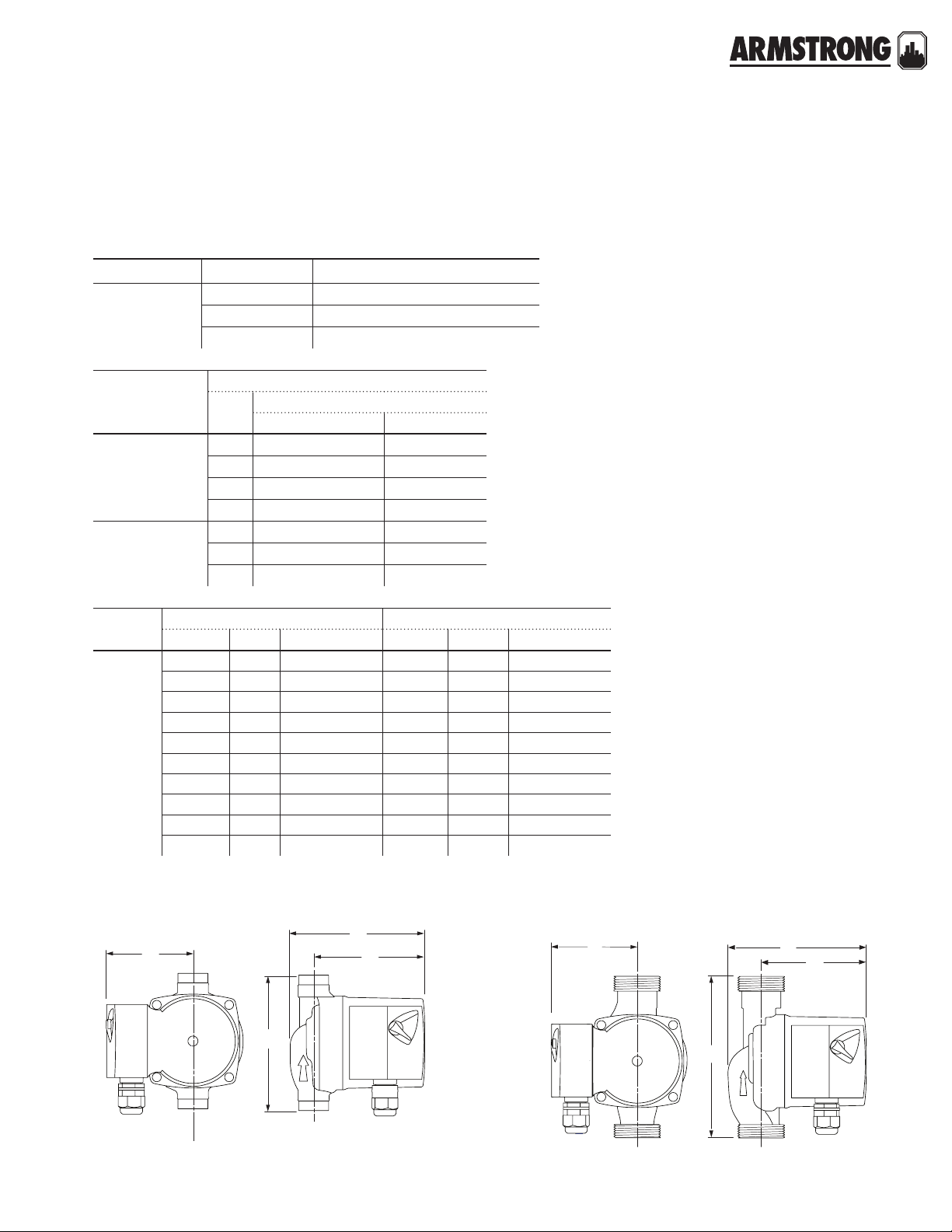
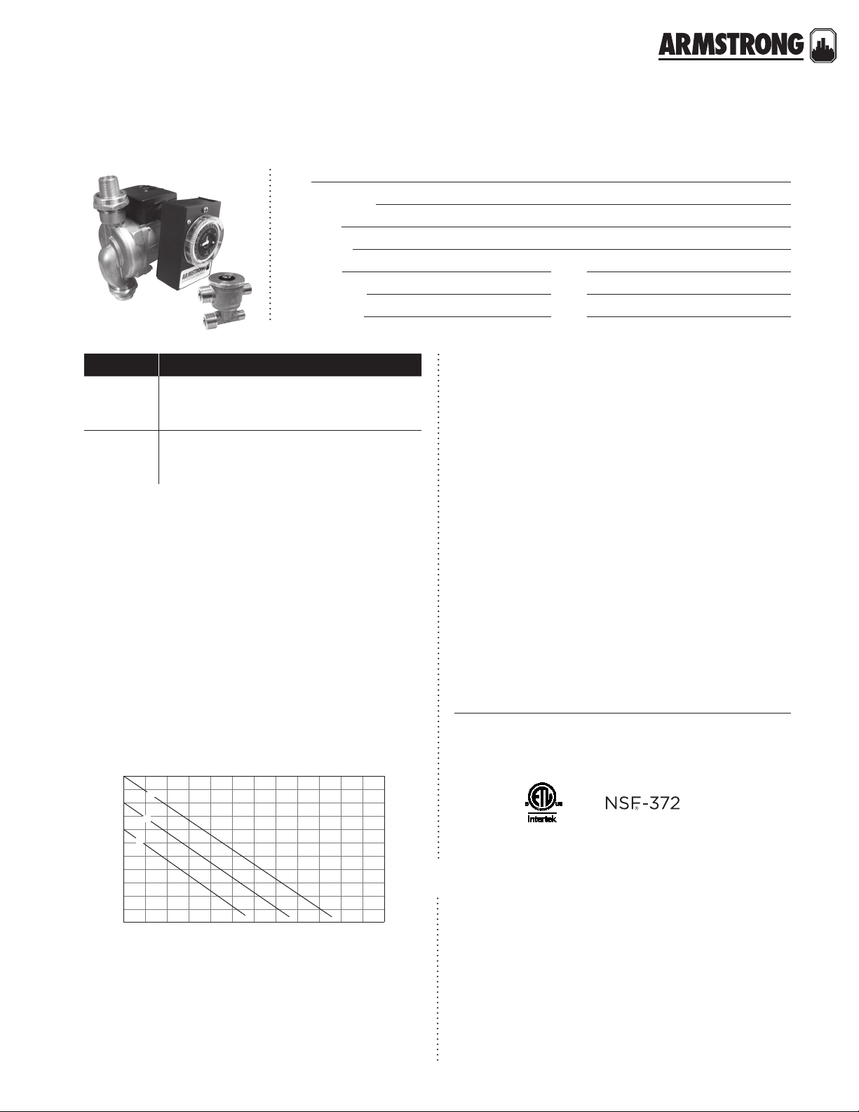
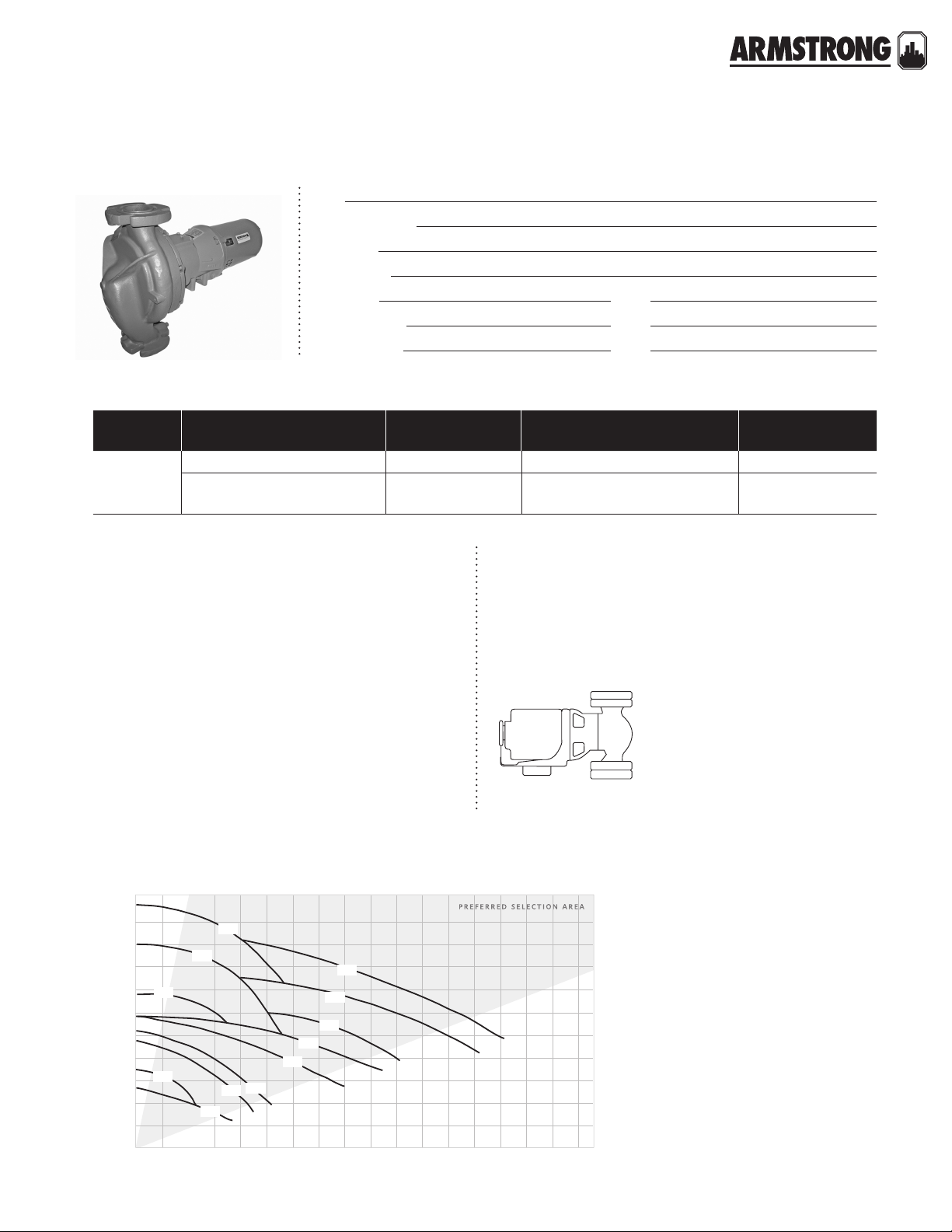
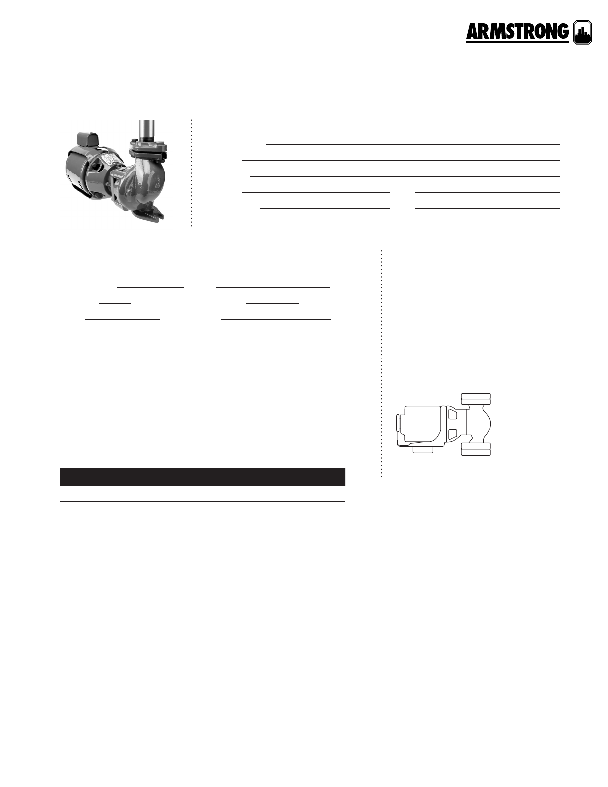
DESIGN ENVELOPE COMPASS CIRCULATORS
VARIABLE SPEED WET ROTOR
|
SUBMITTAL
Job:
Representative:
Engineer:
Contractor:
Order no: Date:
Submitted by: Date:
Approved by: Date:
technical data
Supply voltage: 1 × 115 v – 10%/+ 6%, 60 Hz
minimum maximum
Amp 0.05 0.65
Watt 5
Motor protection: The pump requires no external
motor protection.
Maximum working temperature: 230°f (110°c) maximum
Maximum working pressure: 150 psi (10 bar).
Maximum relative air humidity (rh): 95%.
Flow range: 0 – 20 USgpm (0 to 1.26 L/s)
Head range: 0 – 20.0 feet (0 to 6.09 m)
Enclosure class: Type 2
Insulation class: h
Certification:
ulstd.778 certified to csa std. c22.2 no.108-01)
*nsf 372 (for stainless steel models)
etl listed for US and Canada (conforms to
45
inlet pressure
Minimum inlet pressure in relation to liquid temperature:
To avoid condensation in the control box and stator, the
liquid temperature must always be higher than the
ambient temperature.
ambient
temperature
32°f (0°c) 35.6°f (2°c) 230°f (110°c)
50°f (10°c) 10°c (50°f) 230°f (110°c)
68°f (20°c) 68°f (20°c) 230°f (110°c)
86°f (30°c) 86°f (30°c) 230°f (110°c)
95°f (35°c) 95°f (35°c) 194°f (90°c)
104°f (40°c) 104°f (40°c)
liquid temperature
min. max.
materials of construction
Pump body: Cast iron (closed systems)
Stainless steel* (open s ystems)
Impeller: Noryl
Shaft: Ceramic
Bearings: Ceramic
Gasket material: epdm
158°f (70°c)
liquid temperature minimum inlet pressure
150°f (65°c) 3.0 ft (0.91 m)
167°f (75°c) 4.4 ft (1.34 m)
194°f (90°c) 9.2 ft (2.8 m)
230°f (110°c) 36.1 ft (11.0 m)
Sound pressure level:
lower than 43 dB(A).
Ambient temperature: 32°f (0°c) – 104°f (40°c)
Pumped liquids: Water or water Glycol mix.
Liquid temperature: 36°f (2°c) – 230°f (110°c)**
The sound pressure level of the pump is
hardware kit
Companion flange kit (contains two (2) flanges,
hardware and gaskets)
Cast iron: 0.75", 1", 1.25", 1.5"
Bronze: 0. 75", 1 ", 1 . 2 5", 1 .5"
HYDRONIC SOLUTIONS CATALOG
|
3
Page 4
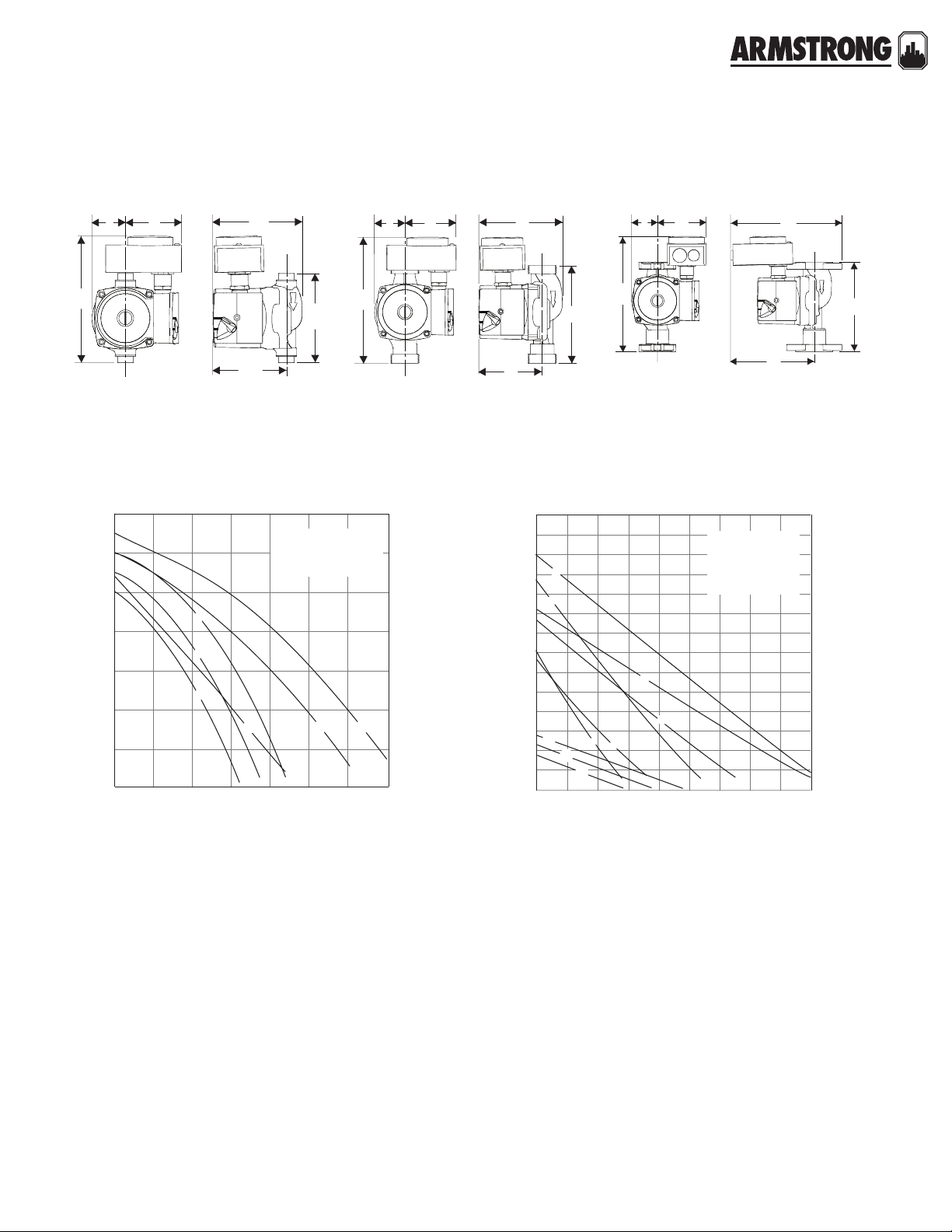
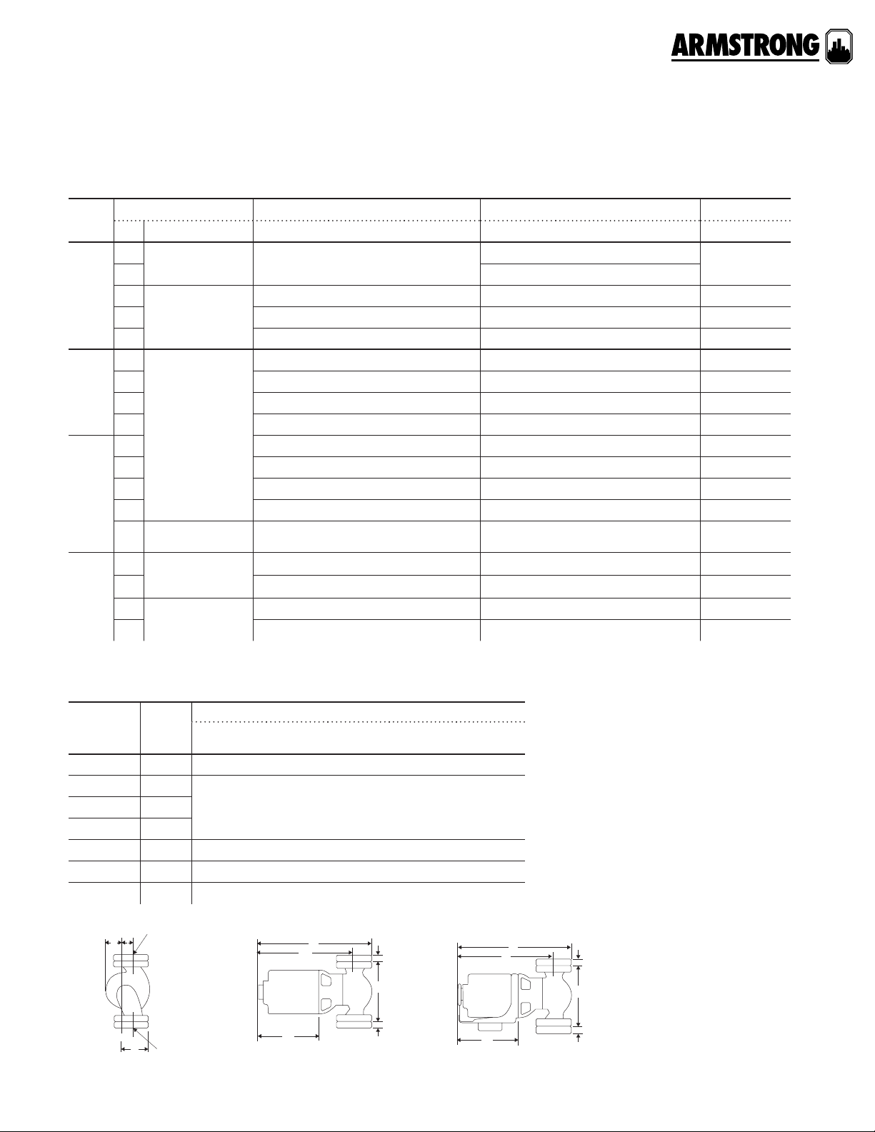
DESIGN ENVELOPE COMPASS CIRCULATORS
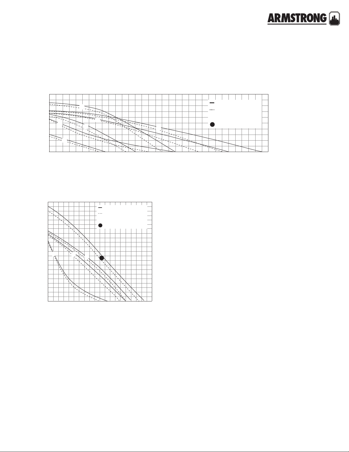
compass performance curves
head - ft.wg.
d
VARIABLE SPEED WET ROTOR
dimensions and weights
|
SUBMITTAL
stainless steel* part number a b c d e f g
Compass 20-20 ss
flange
180203-607
cast iron part number a b c d e f g
Compass 20-20 ci
flange
note:
All dimensions are in inches (mm) and weights in lbs (kg).
*Certified <0.25 weighted average percent lead and complies with California Health and
Safety Code Section 116875 (commonly known as ab 1953).
** For open systems, it is recommended that the liquid temperature be less than 150°f
(65°c) to avoid precipitation of calcium.
180203-606
compass performance curves
24
22
20
18
16
14
12
10
8
4
2
0
pc3
pc4
pc2
2
0
auto
466
i
10
8
flow - usgpm
pc1
6.50
(165)
6.50
(165)
7.08
(180)
7.08
(180)
5.75
(146)
5.75
(146)
4.00
(102)
4.00
(102)
2.00
(50)
2.00
(50)
3.25
(80)
3.25
(80)
5.31
(135)
5.31
(135)
connection
type& size
Flange – (2) ½"
dia. bolt holes
connection
type & size
Flange – (2) ½"
dia. bolt holes
weight
8.0 (3.6)
weight
8.0 (3.6)
compass flange
f
(on center)
e
a
ii
16
14
12
iii
20 22
18
b
c
g
speed pressure curve
iii
ii
i
auto
pc4
pc2
pc3
pc1
Lights on the display indicate the Control mode selected.
HYDRONIC SOLUTIONS CATALOG
|
4
Page 5
back to
<
contents
ASTRO 2 CIRCULATORS
THREE SPEED
|
SUBMITTAL
Job:
Representative:
Engineer:
Contractor:
Order no: Date:
Submitted by: Date:
Approved by: Date:
technical data
Flow range: 0 to 64 USgpm (0 to 4.04 L /s)
Head range: 0 to 42.0 feet (0 to 12.8 m)
Maximum fluid temperature: 185°f / 85°c (astro 286 up to 1.35a)
150°f / 65°c (astro 286 over 1.35a)
230°f / 110°c† (all others)
Maximum working pressure: 150 psi (1034 kPa)
Approvals: listed certified
†
For open systems, it is recommended that the fluid temperature be less
than 150°f (66°c) to avoid precipitation of calcium.
materials of construction
Pump body: Cast iron (closed systems)
Lead free bronze* (open systems)
Stainless steel* (open systems)
Impeller: Noryl
Bearings: Ceramic Gasket material: epdm
* Certified <0.25 weighted average percent lead and complies with
California Health and Safety Code Section 116875 (commonly known
as ab 1953).
Shaft: Ceramic
motor data
model electrical input speed full load amp draw (a) nominal power (w)
3 1.06
Astro 210ci/ss
Astro 220ssu
Astro 225bs
Astro 225ssu
Astro 230ss/ci/ci–r
Astro 250ss/ci/ci–r
Astro 280ci/ss
Astro 290ci/ss
Astro 280ci/ss 230v
Astro 286ci/ss
115v, 60hz
Single phase
23 0v, 60hz
Single phase
2 1.50
1 1.72
3 0.29
2 0.27
1 0.20
3 0.64
2 0.49
1 0.38
3 0.69
2 0.55
1 0.43
3 0.81
2 0.58
1 0.45
3 0.98
2 0.79
1 0.65
3 1.90
2 1.80
1 1.50
3 1.90
2 1.60
1 1.40
3 0.90
2 0.86
1 0.80
1 1.60
200
33
75
83
97
117
218
218
210
370
HYDRONIC SOLUTIONS CATALOG
|
5
Page 6

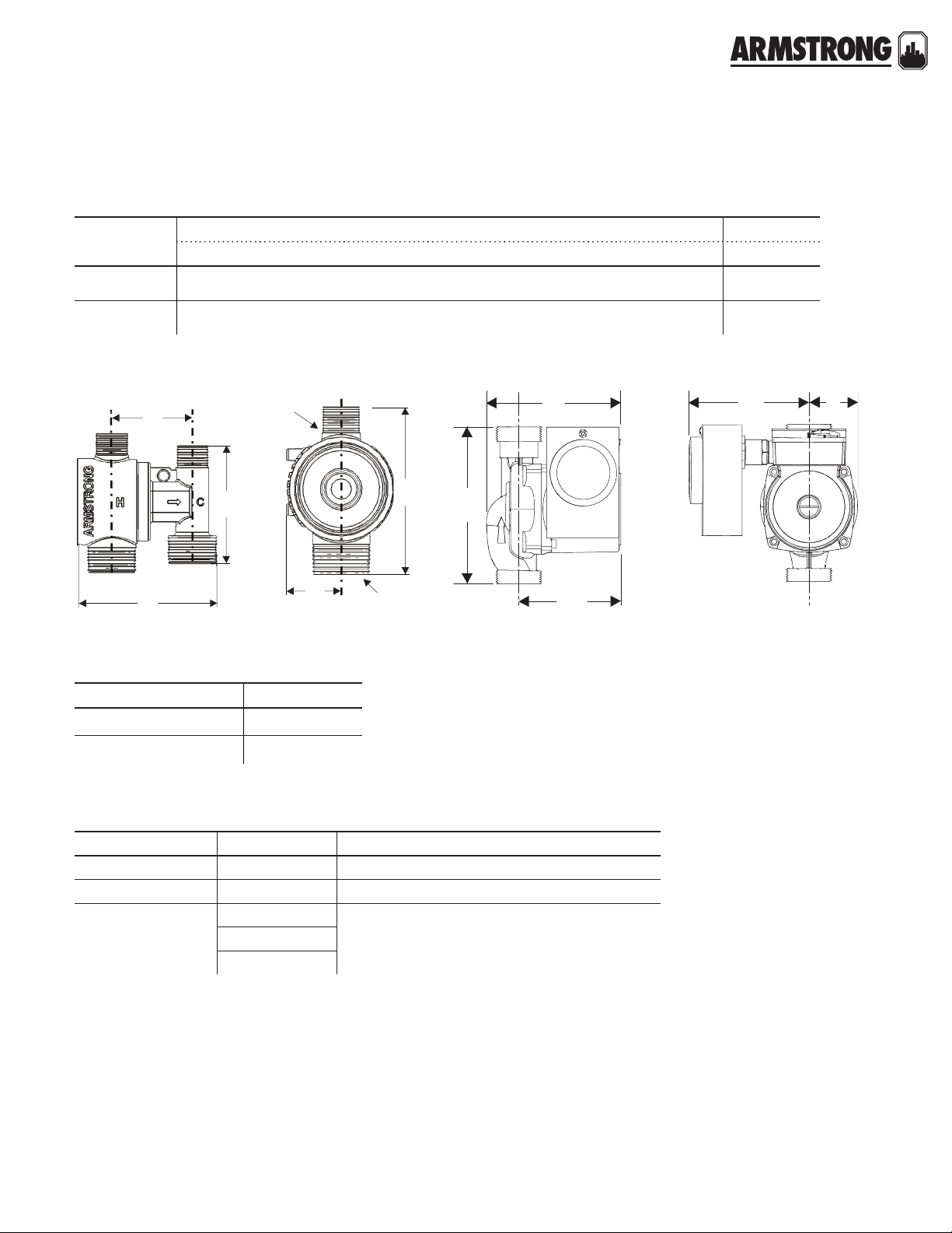
ASTRO 2 CIRCULATORS
THREE SPEED
|
SUBMITTAL
dimension data - inches (mm)
lead free bronze* a b c d e f connection type & size weight
Astro 225bs ½" swt 5.00 (127) 5 .0 0 (127) 4.13 (105) — 3 .00 (76) — Sweat – ½" 6.0 (2.7)
Astro 225bs ¾" swt 5.0 0 (127) 5.0 0 (127) 4.13 (105) — 3.0 0 (76) — Sweat – ¾" 6.0 (2.7)
stainless steel* a b c d e f connection type & size weight
Astro 220ssu** 6.00 (152) 5 .00 (127) 4.0 0 (102) — 3 .00 (76) — Union – 1¼" npsm 6.5 (2.9)
Astro 225ssu** 6.00 (152) 5 .0 0 (127) 4.0 0 (102) — 3 .00 (76) — Union – 1¼" npsm 6.5 (2.9)
Astro 230ss** 6 . 3 8 (162) 6. 0 0 (150) 4.00 (102) 4.0 0 (102) 3.00 (76) 3.25 (80) Flange – (2) ½" dia. bolt holes 8 .0 (3. 6)
Astro 250ss** 6.38 (162) 6.0 0 (150) 4.00 (102) 4. 0 0 (102) 3.00 (76) 3.25 (80) Flange – (2) ½" dia. bolt holes 8 .0 (3.6)
Astro 210ss** 6. 5 0 (165) 7. 25 (18 4) 4 .87 (124) 4 .0 0 (102) 3.5 0 (9 0) 3.13 (80) Flange – (2) ½" dia. bolt holes 10 .1 (4.6)
Astro 280ss (230v)** 6.50 (165) 6.75 (171) 4 . 87 (124) 4 .0 0 (102) 3.5 0 (9 0) 3.13 (80) Flange – (2) ½" dia. bolt holes 10 .1 (4.6)
Astro 286ss** 6.50 (16 5) 6 . 3 8 (162) 4.87 (124) 4 .00 (102) 3.5 0 (90) 3.13 (80) Flange – (2) ½" dia. bolt holes 10.1 (4.6)
Astro 29 0ss** 8.5 0 (216) 6. 65 (169) 5.20 (13 2) 4 .0 0 (102) 3.50 (9 0) 3.45 (88) Flange – (2) ½" dia. bolt holes 13.2 (6.0)
cast iron a b c d e f connection type & size weight
Astro 230ci** 6.38 (162) 6.0 0 (15 0) 4.00 (102) 4.0 0 (102) 3 .00 (76) 3.25 (80) Flange – (2) ½" dia. bolt holes 8 .0 (3.6)
Astro 230ci-r** 6.38 (162) 5 . 63 (137) 4. 0 0 (102) 4.00 (102) 3.0 0 (76) 3. 25 (80) Flange – (2) ½" dia. bolt holes 8.0 (3 .6)
Astro 250ci** 6 . 3 8 (162) 6.00 (150) 4.0 0 (102) 4.0 0 (102) 3 .00 (76) 3.25 (80) Flange – (2) ½" dia. bolt holes 8 .0 (3.6)
Astro 250ci-r** 6. 3 8 (162) 5.6 3 (137) 4.00 (10 2) 4.0 0 (102) 3.0 0 (76) 3.25 (8 0) Flange – (2) ½" dia. bolt holes 8.0 (3.6)
Astro 210ci** 6.50 (16 5) 7.2 5 (184) 4 . 87 (124) 4.0 0 (102) 3.5 0 (9 0) 3.13 (80) Flange – (2) ½" dia. bolt holes 10 .1 (4.6)
Astro 280ci (230v)** 6.50 (16 5) 6 . 3 8 (162) 4.87 (124) 4 .00 (102) 3.50 (90) 3.13 (80) Flange – (2) ½" dia. bolt holes 10.1 (4.6)
Astro 286ci** 6.50 (16 5) 6 . 3 8 (162) 4.87 (124) 4 .00 (102) 3.50 (90) 3.13 (80) Flange – (2) ½" dia. bolt holes 10.1 (4.6)
Astro 290ci** 8.50 (216) 6.6 5 (169) 5.20 (132) 4. 0 0 (102) 3.50 (90) 3.45 (88) Flange – (2) ½" dia. bolt holes 13.2 (6.0)
note: All dimensions are in inches (mm) and weights in lbs (kg).
** Removable check valve installed at pump outlet.
mounting orientation
right wrong
part numbers
model part number
Astro 220ssu w½" swt 110223-301
Astro 220ssu w¾" swt 110223-302
Astro 220ssu 110223-309
Astro 225bs ½" swt 110223-303
Astro 225bs ¾" swt 110223-304
Astro 225ssu 110223-310
Astro 230ci 110223-305
Astro 230ci-r 110223-315
Astro 230ss 110223-306
HYDRONIC SOLUTIONS CATALOG
|
6
model part number
Astro 250ci 110223-307
Astro 250ci-r 110223-317
Astro 250ss 110223-308
Astro 280ci 110223-320
Astro 280ss 110223-321
Astro 280ci (230v) 110223-322
Astro 280ss (230v) 110223-323
Astro 286ci (230v) 110223-324
Astro 286ss (230v) 110223-325
model part number
Astro 210ci 110223-326
Astro 210ss 110223-327
Astro 290ci 110223-328
Astro 290ss 110223-329
Page 7
ASTRO 2 CIRCULATORS
THREE SPEED
|
SUBMITTAL
accessories
lead free* union fitting sets (contains two (2) half unions and gaskets)
model part number connection
Astro
220ssu/225ssu
model
Astro
210/230/250
/280/286
Compass
Astro 290
810120-320 1.25" npsm × 0.5" sweat lead free
810120-322 1.25" npsm × 0.75" sweat lead free
810120-324 1.25" npsm × 0.75" fnpt lead free
flange kits
size
lead free bronze* cast iron
0.75" 816013-841 816013 -111
1" 816012-841 816012-111
1.25" 816011- 841 816011-111
1.5" 8160 09-841 816009-111
1" 806073-841 806073-111
1.25" 804300-841 804300-111
1.5" 804301-841 804301-111
item number
model
cif-050t ½" 110124-100 ff-050t ½" 110124-200
cif-075t ¾" 110124-00 0 ff-075t ¾" 110124-201
cif-100t 1" 110124-001 ff-100t 1" 110124-202
All Astro
flange
models
astro 225bs
cif-125t 1¼" 110124-002 ff-125t 1¼" 110124-203
cif-150t 1½" 110124-003 ff-150t 1½" 110124-204
cif-050s ½" 110124-150 ff-050s ½" 110124-250
cif-075s ¾" 110124-050 ff-075s ¾" 110124-251
cif-100s 1" 110124-051 ff-100s 1" 110124-252
cif-125s 1¼" 110124-052 ff-125s 1¼" 110124-253
cif-150s 1½" 110124-053 ff-150s 1½" 110124-254
e
cif flex flanges
model size item number model size item number
astro 220ssu, 225ssu
b
c
a
e
b
c
a
HYDRONIC SOLUTIONS CATALOG
|
7
Page 8

ASTRO 2 CIRCULATORS
head - feet
head - metres
flow - usgpm
flow - l/s
head - feet
head - metres
flow - usgpm
flow - l/s
THREE SPEED
|
SUBMITTAL
astro 230ss/ci, 250ss/ci
e
a
f
(on center)
d
astro 280ci, 290ci/ss, 286ci/ss
e
astro 230ci-r, 250ci-r
b
c
b
c
e
f
(on center)
d
astro 280ss, 210ci/ss
e
a
b
c
b
c
performance curve
astro 225bs, 225ssu astro 250, 230, 220
HYDRONIC SOLUTIONS CATALOG
|
8
(on center)
d
00.130.25
14
12
10
8
6
4
2
0
024
a
f
0.38 0.50 0.63
3
0.76 0.88
astro 225bs
astro 225ssu
4.3
3.7
3.0
2.4
0 0.13 0.25 0.38 0.50 0.63 0.76 0.88 1.01 1.14
28
24
3
20
2
16
a
f
(on center)
d
astro 250
astro 230
astro 220
8.5
7.3
6.1
4.9
2
1
1 2 3
1.8
1.2
0.6
12
3
8
2
3
1
4
2
1
3.7
2.4
1.2
1
6810
12 14
0
0
024681012141618
0
Page 9
ASTRO 2 CIRCULATORS
flow - usgpm
flow - l/s
head - feet
head - metres
flow - usgpm
flow - l/s
head - feet
head - metres
THREE SPEED
|
SUBMITTAL
astro 210, 290
0.250 0.50 0.76 1.01 1.26 1.51 1.77 2.02 2.27 2.78 3.03 3.79 4.043.533.282.52
20
16
12
1
8
4
1
0
0481216202428323644486064565240
3
2
2
astro 280, 286
0 0.50 1.01 1.51 2.02 2.52
44
40
32
without check valve
with check valve
astro 280
astro 286
13.4
12.2
9.8
3
without check valve
with check valve
astro 210
astro 290
6.1
4.9
3.7
2.4
1.2
0
24
1
16
8
0
0816 24 32 40
2
3
7.3
4.9
2.4
0
HYDRONIC SOLUTIONS CATALOG
|
9
Page 10

10
HYDRONIC SOLUTIONS CATALOG
|
Page 11
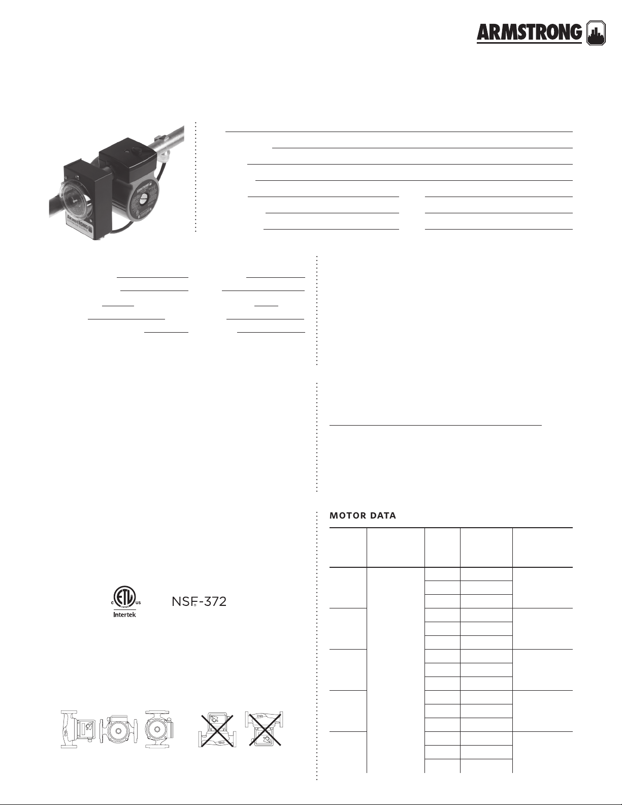
motor data
back to
<
contents
ASTRO 2
|
HOT WATER RE-CIRCULATION SYSTEMS
SUBMITTAL
Job:
Representative:
Engineer:
Contractor:
Order no: Date:
Submitted by: Date:
Approved by: Date:
pump design data
Pump model: Flange size:
No. of pumps:
Capacity:
Head:
ft (m) Liquid:
Companion flanges: Included:
Note:
USgpm (L/s) Temperature: °f (°c)
application
Armstrong Astro 2 hot water re-circulation systems
automatically circulate water through domestic hot water
distribution pipes. This helps to ensure that everyone in the
household has ‘instant’ hot water at the tap when they need
it, while also helping to conserve water and save water heating energy costs. All systems are assembled, wired, tested
and then shipped, ready for installation.
technical data
Power connection: 6.0 ft. (1.8 m) power cord, molded duplex
plug with ground
Environment: Indoor use only
Flow range: 0 to 64 USgpm (0 to 4.04 L /s)
Head range: 0 to 42.0 feet (0 to 12.8 m)
Max. working pressure: 150 psi (1034 kPa)
Max. water temperature: 230°f (110°c)
Ambient temperature: 39°f (4°c) to 104°f (40°c)
Low temperature switchpoint
High temperature switchpoint
Clock/timer: 12 hour analog clock with am/pm indication
Timer settings: Individual mechanical toggles for each 15
minute interval over 24 hours
Manual override: Three position slide switch; on/auto/o
Approvals: listed certified
1 High/low temperature switchpoints are as measured on pipe surface with the
Aquastat (ta models only).
†
For open systems, it is recommended that the fluid temperature be less
than 150°f (66°c) to avoid precipitation of calcium.
mounting orientation
right wrong
†
1
: 85°f (29°c) ± 10%
1
: 105°f (40°c) ± 10%
materials of construction
Pump body: Lead free bronze* (bs models)
Stainless steel* (ss models)
Impeller: Noryl
Bearings: Ceramic Gasket material: epdm
* Certified <0.25 weighted average percent lead and complies with California
Health and Safety Code Section 116875 (commonly known as ab 1953).
model
astro
220ssu
astro
225bs
astro
225ssu
astro
230ss
astro
250ss
Shaft: Ceramic
electrical
input
115v, 60hz
Single phase
speed
3 0.29
2 0.27
1 0.20
3 0.64
1 0.38
3 0.69
1 0.43
3 0.81
1 0.45
3 0.98
2 0.79
1 0.65
full load
amp
draw (a)
nominal
power (w)
33
752 0.49
832 0.55
972 0.58
117
11
HYDRONIC SOLUTIONS CATALOG
|
Page 12
ASTRO 2
SUBMITTAL
|
HOT WATER RE-CIRCULATION SYSTEMS
dimension data - inches (mm)
model a b c d e f
astro 225bs
astro 220/225ssu
astro 230/250ss
note: All dimensions are in inches (mm)
5. 0 (127) 6 . 5 (165) 5.6 (142) 7.1 (180) 4.3 (110) 1.8 (4 6)
5. 0 (127) 5 . 3 (134) 4.4 (112) 6.3 (160) 3.4 (86) 1 . 8 (46)
6.4 (162) 8 .7 (221) 6.8 (173) 7.0 (178) 3.7 (93) 1.8 (46)
electrical
model connection size cord timer aquastat
data @ 115
Vac, 60 Hz
astro 220ssu050s-ta*
astro 220ssu075s-ta*
astro 225bs050s-ta
astro 225bs075s-ta Sweat ¾"
astro 220ssu-ta npsm union 1¼"
astro 225ssu-ta npsm union 1¼"
astro 230ss-ta 2 bolt flange 2 bolt flange
astro 250ss-ta 2 bolt flange 2 bolt flange
astro 220ssu050s-t* Sweat ½"
astro 220ssu075s-t* Sweat ¾"
astro 225bs050s-t Sweat ½"
astro 225bs075s-t Sweat ¾"
astro 220ssu-t npsm union 1¼"
astro 225ssu-t npsm union 1¼"
astro 230ss-t 2 bolt flange 2 bolt flange
astro 250ss-t 2 bolt flange 2 bolt flange
astro 220ssu050s-lc* Sweat ½"
astro 220ssu075s-lc* Sweat ¾"
astro 225bs050s-lc Sweat ½"
astro 225bs075s-lc Sweat ¾"
astro 220ssu-lc npsm union 1¼"
astro 225ssu-lc npsm union 1¼"
astro 230ss-lc 2 bolt flange 2 bolt flange
astro 250ss-lc 2 bolt flange 2 bolt flange
note: All weights are in lbs. (kg) *Union model with sweat hardware kit.
Sweat ½"
Sweat ¾"
Sweat ½"
ü ü ü
ü ü ü
ü ü ü
ü ü ü
ü ü ü
ü ü ü
ü ü ü
ü ü ü
ü ü
ü ü
ü ü
ü ü
ü ü
ü ü
ü ü
ü ü
ü
— — 0.29 A, 33W 7.00 (3.18) 110223-340
ü
— — 0.29 A, 33W 7.00 (3.18) 110223-341
ü
— — 0.64 A, 75W 6.50 (2.95) 110223-342
ü
— — 0.64 A, 75W 6.50 (2.95) 110223-343
ü
— — 0.29 A, 33W 7.00 (3.18) 110223-344
ü
— — 0.69 A, 83W 7.00 (3.18) 110223-345
ü
— — 0.81 A, 97W 9.00 (4.08) 110223-348
ü
— — 0.98 A, 117W 9.00 (4.08) 110223-349
— 0.29 A, 33W 7.50 (3.40) 110223-240
— 0.29 A, 33W 7.50 (3.40) 110223-241
— 0.64 A, 75W 7.00 (3.18) 110223-242
— 0.64 A, 75W 7.00 (3.18) 110223-243
— 0.29 A, 33W 7.50 (3.40) 110223-244
— 0.69 A, 83W 7.50 (3.40) 110223-245
— 0.81 A, 97W 10 .0 0 (4.54) 110223-248
— 0.98 A, 117W 10.00 (4. 54) 110223-249
0.29 A, 33W 7.50 (3.40) 110223-140
0.29 A, 33W 7.50 (3.40) 110223-141
0.64 A, 75W 7.00 (3.18) 110223-142
0.64 A, 75W 7.00 (3.18) 110223-143
0.29 A, 33W 7.50 (3.40) 110223-144
0.69 A, 83W 7.50 (3.40) 110223-145
0.81 A, 97W 10.0 0 (4.54) 110223-148
0.98 A, 117W 10.00 (4. 54) 110223-149
weight
pa r t
numbe r
12
accessories
24 hour timer
model part number
24 hour timer 810123-130
See page 49 for the details on 24-Hour Timer
HYDRONIC SOLUTIONS CATALOG
|
aquastat
model part number
½" 110123-120
¾" 110123-121
See Page 85 for the details on Aquastat models.
Page 13
ASTRO 2
|
HOT WATER RE-CIRCULATION SYSTEMS
SUBMITTAL
lead free* union fitting sets (contains two (2) half unions and gaskets)
model part number connection
810120-320 1.25" npsm × 0.5" sweat lead free
Astro 220ssu/225ssu
model
Astro
210/230/250
/280/286
Compass
Astro 290
810120-322 1.25" npsm × 0.75" sweat lead free
810120-324 1.25" npsm × 0.75" fnpt lead free
flange kits
size
lead free bronze* cast iron
0.75" 816013-841 816013-111
1" 816012-841 816012-111
1.25" 816011- 841 816011-111
1.5" 8160 09-841 816009-111
1" 806073-841 8 0 6073-111
1.25" 804300-841 804300-111
1.5" 804301-841 804301-111
item number
model
All Astro
flange
models
cif flex flanges
model size item number model size item number
cif-050t ½" 110124-100 ff-050t
cif-075t ¾" 110124-000 ff-075t
cif-100t 1" 110124-001 ff-100t
cif-125t 1¼" 110124- 002 ff-125t
cif-150t 1½" 110124-003 ff-150t
cif-050s ½" 110124-150 ff-050s
cif-075s ¾" 110124-050 ff-075s
cif-100s 1" 110124-051 ff-100s
cif-125s 1¼" 110124-052 ff-125s
cif-150s 1½" 110124-053 ff-150s
½" 110124-200
¾" 110124-201
1" 110124-202
1¼" 110124-203
1½" 110124-204
½" 110124-250
¾" 110124-251
1" 110124-252
1¼" 110124-253
1½" 110124-254
13
HYDRONIC SOLUTIONS CATALOG
|
Page 14
ASTRO 2
b
c
a
fe
b
c
f
e
b
c
a
f
e
head - feet
head - metres
flow - usgpm
flow - l/s
head - feet
head - metres
flow - usgpm
flow - l/s
|
HOT WATER RE-CIRCULATION SYSTEMS
SUBMITTAL
astro 225bs astro 230/250ssastro 220/225ssu
d
d
d
performance curve
astro 225bs, 225ssu astro 250, 230, 220
00.130.25
14
12
10
8
6
4
2
0
024
0.38 0.50 0.63
3
2
1
1 2 3
6810
0.76 0.88
astro 225bs
astro 225ssu
12 14
4.3
3.7
3.0
2.4
1.8
1.2
0.6
0
0 0.13 0.25 0.38 0.50 0.63 0.76 0.88 1.01 1.14
28
24
3
20
2
16
12
8
3
1
4
2
1
1
0
024681012141618
3
2
astro 250
astro 230
astro 220
a
8.5
7.3
6.1
4.9
3.7
2.4
1.2
0
HYDRONIC SOLUTIONS CATALOG
|
14
Page 15
back to
<
contents
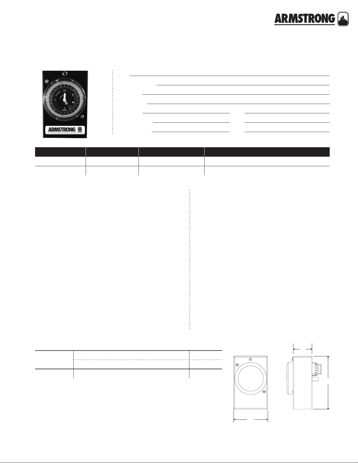
ASTRO 2
quantity tag no. model no. comments
|
24 HOUR TIMER
Job:
Representative:
Engineer:
Contractor:
Order no: Date:
Submitted by: Date:
Approved by: Date:
|
SUBMITTAL
technical data
Description: 24 hour timer
Application: Time actuated
Shortest switching interval: ¼ hour (15 minutes)
Manual switch modes: Timer,
Ambient temperature range: -40°f to 180°f (-40°c to 82°c)
Power consumption: 120 v, 0.5 w
Supply voltage: 110-120 vac, 60 Hz
Terminals: ¼" spade terminals
Switch rating: Type: Spot
Resistive: 21a
Tungsten: 1350 w
Inductive: 1 hp @ 120 vac; 2 hp @ 240 vac
on/o pump control
on override, o override
part numbers
24 hour timer: 810123-130
application
Armstrong 24 hour timers provide on/o pump control
according to preset operating times in order to increase
occupant comfort and improve the overall eciency
of domestic hot water re-circulation systems. The 24
hour timers are designed only for use with specified
Armstrong Astro series wet rotor circulators installed in
indoor hot water re-circulation applications.
Typical timer applications will cycle the pump at preset
times, allowing the user to select operation of the circulating pump during high peak usage periods in order to
decrease the delivery time to outlet fixtures and reduce
wasted water.
The timer control is programmable to ¼ hour intervals
within a 24 hour time frame utilizing a user-friendly
analog clock timer with hour and minute hands, two
directional arrows, and am/pm time setting.
dimension data - inches (mm)
model
hour timer
24
dimensions inches (mm) weight
a b c lbs (oz.)
2.74 (70) 1.50 (38) 4.23 (107) 0.19 (3.0)
b
c
a
HYDRONIC SOLUTIONS CATALOG
|
15
Page 16

16
HYDRONIC SOLUTIONS CATALOG
|
Page 17
a
c
back to
<
contents
AQUASTAT CONTROLS
½” & ¾”
|
SUBMITTAL
Job:
Representative:
Engineer:
Contractor:
Order no: Date:
Submitted by: Date:
Approved by: Date:
technical data
Description: Aquastat (thermostatic) switch
Application: Clip-on thermostatic control for Astro circulators
Type: Bi-metallic disc, snap-acting
Enclosure: Environmentally sealed
Mounting: Clip-on mount for ½" ( 12.7 mm) i.d. copper tube [X" (15.8 mm) o.d.]
Clip on mount for ¾" (19.0 mm) i.d. copper tube [Y" (22.2 mm) o.d.]
Contact rating: 10 a @ 120 v, 60 Hz resistive; 5 a @ 240 v, 60 Hz resistive
Temperature Rating* : 105±5°f (40±2°c) pump switches o
85±6°f (29±3°c) pump switches on
Leads: 2 Leads, awg 18, 14" (356 mm)
12" (305 mm), black insulation, silicon or epoxy overmold
½" (12.7 mm) strip length
* Temperatures indicated are at pipe surface
dimension data - inches (mm)
model
½" Aquastat
¾" Aquastat
dimensions inches (mm)
a b c d e f g h j
0.56
(14.2)
0.56
(14.2)
1.1 2
(28.4)
1.1 2
(28.4)
0.62 5 (15. 8)
nominal pipe o.d.
0.875 (22.2)
nominal pipe o.d.
1.7
(43 . 2)
1.8
(45 .7)
0.9 6
(24.4)
0.9 6
(24.4)
1.04
(2 6. 4)
1.04
(26.4)
14.0
(355.6)
14.0
(355.6)
b
2.0
(50.8)
2.0
(50.8)
j
h
g
e
d
f
0.5
(12.7)
0.5
(12.7)
part numbers
model part numer
½" Aquastat 110123-120
¾" Aquastat 110123-121
17
HYDRONIC SOLUTIONS CATALOG
|
Page 18
AQUASTAT CONTROLS
½” & ¾”
|
SUBMITTAL
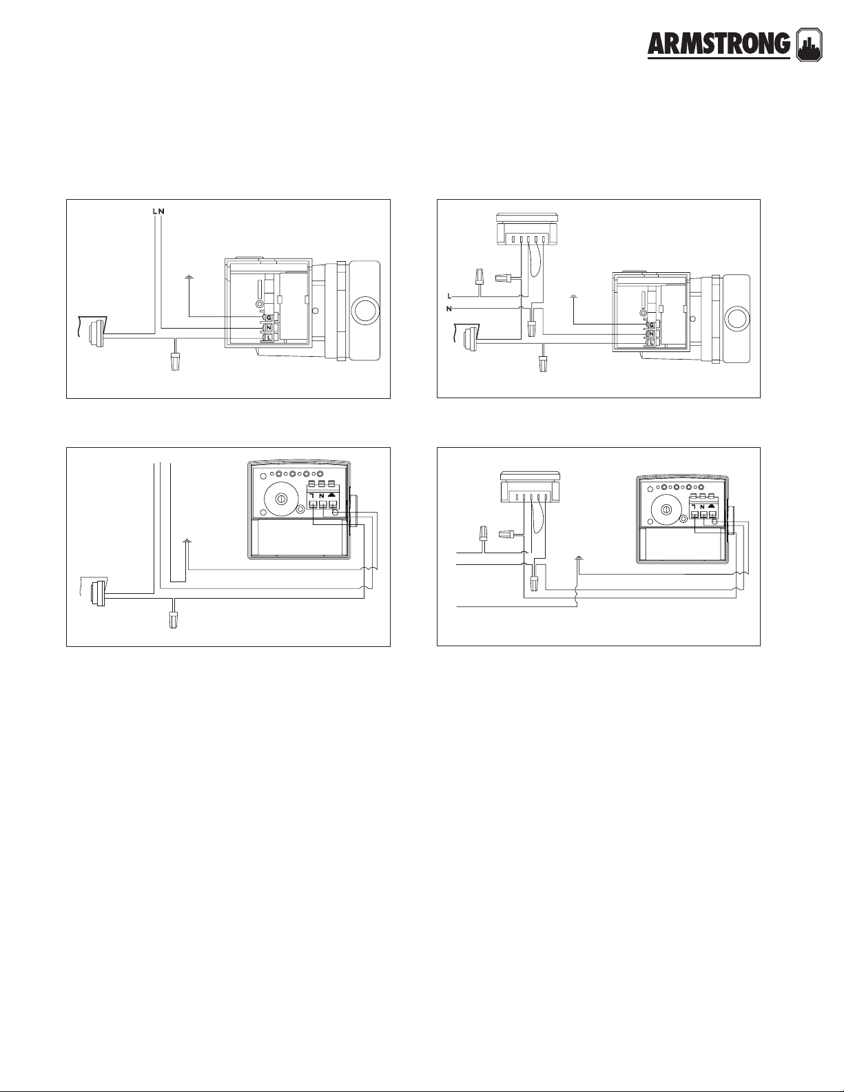
wiring diagram
green
black
white
aquastat
astro series circulator with aquastat control wiring diagram
black
white
aquastat
astro 2 series circulator with aquastat control wiring diagram
white
black
pump
GNL
green
white
black
pump
54321
black
black
white
black
white
aquastat
astro series circulator with 24 hour timer and aquastat control wiring diagram
timer
black
L
white
N
green
G
astro 2 series circulator and 24 hour timer wiring diagram
black
timer
black
ground
screw
white
black
black
ground screw
in timer box
white
black
green
white
black
green
green
white
black
pump
18
HYDRONIC SOLUTIONS CATALOG
|
Page 19
5.5
12
head - feet
flow - usgpm
back to
<
contents
ASTRO EXPRESS 2
HOT WATER RECIRCULATION
Job:
Representative:
Engineer:
Contractor:
Order no: Date:
Submitted by: Date:
Approved by: Date:
|
SUBMITTAL
quantity description
*Astro Express 2 system (Wet rotor circulator
with timer, line cord, union hardware, and one
Astro Express lf valve)
*Astro Express lf valve (only) for lengthy
branches to additional faucets o main
distribution pipe
materials of construction
astro express 2 circulator
Pump casing: Astro 220ssu with 1¼” npsm union threads
Power connection: 6.0 ft (1.8
plug with ground
Impeller: pa66
Shaft: Ceramic
Bearings/seal: Ceramic/epdm
Union tailpieces: Brass, ¾" fpt (two) and ¾" mpt (one)
Union gaskets: epdm (two)
m) power cord, molded duplex
performance curve
5
3
4
2
1
3
2
technical data
astro express 2 circulator
Power requirements: 115 vac, 60 Hz, 33 w, 0.29 a max.
Max. head (Astro 220ssu): 5.3 ft (1.6 m)
Max. flow (Astro 220ssu): 10.0 gpm (0.63 L/s)
Ambient temperature: 39°f (4°c) to 104°f (40°c)
Clock timer: 12 hour analog clock with am/pm indication
Timer settings: Individual toggles for each 15
interval over 24 hours
Manual override: 3 position slide switch, on/o/auto
astro express lf valve
Housing: Forged eco brass* with noryl cap
Internal components:
epdm o-rings
Connections: Threaded, ½" hot & cold inlets, W"
& cold outlets
Flowrate adjustment: 0 – 100%, multi-turn slotted screw
Mounting: Plastic wall anchor with screw
Environment: Indoor use only
Max. working pressure: 100 psi (689 kPa)
Max. water temperature: 140°f (60°c)
Approvals:
*Complies with Section 116875 of the California Health and Safety Code and
Vermont Act 193. (Lead content of all wetted surface is 0.25% or less.)
Stainless steel and plastic with
listed certified
minute
hot
1
0
024
6810
mounting orientation
Connect the hot and cold water supply to the Astro
Express lf valve K" threaded inlets. (Stainless steel flex
hose recommended.)
Connect the hot and cold Astro Express lf valve W"
threaded outlets to the faucet. (Stainless steel flex hose
recommended.)
Secure the valve to the wall under the sink, using the plastic
wall anchor and screw.
19
HYDRONIC SOLUTIONS CATALOG
|
Page 20
ASTRO EXPRESS 2
ef
c
d
cold
hot
HOT WATER RECIRCULATION
|
SUBMITTAL
dimension data - inches (mm)
product
Astro Express
2 circulator
Astro Express
lf valve
hot
dimensions inches (mm) weight
a b c d e f g lbs (kg)
6.00(152) 5.00 (127) 4.0 0 (102) — 5.00 (127) 1. 80 (46) —
2.50 (63) 1.50 (38) 2.10 (53) 2 . 60 (6 6) 0.8 0 (20) W"ips K" ips
f
b
faucet
supply
c
cold
e
10.00 (4.45)
0.50 (0.23)
astro express 2 circulatorastro express lf valve
b
a
a
g
part numbers
model part numer
Astro Express 2 circulator 110223-401
Astro Express lf valve 561100LF- 001
replacements parts
product part no.
Astro Express lf valve 561100LF- 001 See page 84 for the details on Astro Express lf valve
Timer 810123-130 See page 49 for the details on 24 hour timer
Union kits
(Lead free brass*)
810120-320
See page 181 for the details on Union Fitting Sets810120-322
810120-324
20
HYDRONIC SOLUTIONS CATALOG
|
Page 21
p
a
Based on 1800 rpm, 60 Hz motors. For 50 Hz motors write for special capacity charts.
flow - usgpm
flow - l/s
head - feet
head - meters
horizontal mounting
back to
<
contents
S&H 3-PIECE CIRCULATORS
S MODELS
|
SUBMITTAL
Job:
Representative:
Engineer:
Contractor:
Order no: Date:
Submitted by: Date:
Approved by: Date:
materials of construction
part name bronze fitted lead free bronze*
Pump Body Cast iron Lead free Bronze
Impeller: Non-ferrous
Bearings: Sleeve - Oil lubricated**
Maintenance free - Permanently lubricated***
Seal: Mechanical
Stationary seal face: Sintered silicon carbide
Coupler: s25-s46: Flexible, 4 - Spring;
s55-s69: Flexible spacer type
Motor: Single phase - 1800 rpm - Resilient mounted
Three phase - 1800 rpm - Resilient mounted
mounting orientation
The pump should be installed in a position to
permit proper lubrication of bearings and servicing.
Motor and bearing bracket are to be kept free
of insulation. Pump and motor unit are designed
to be supported by the in line piping only. Do
not support in any other manner. A height of
approximately 4 feet above floor is recommended.
* Contains less than 0.25% lead, weighted average.
** Alloy shaft with copper sleeve.
*** Stainless steel shaft.
maximum pump oper ating conditions
125 psig at 225°f (863 kPa at 107°c)
performance curve
0 0.63 1.89 3.15 4.41 5.68 6.94 8.209.4610.73
40
35
30
25
20
15
10
5
S3
S2
S4
S5
S4
referred selection are
S6
S5
Based on 1800 rpm, 60 Hz
12.1
10.7
9.1
7.6
6.1
4.6
3.0
1.5
motors. For 50 Hz motors
write for special capacity charts.
0
01030507090 110 130 150 170
0
HYDRONIC SOLUTIONS CATALOG
|
21
Page 22
S&H 3-PIECE CIRCULATORS
a
resilient mountend view side view
S MODELS
dimension data - inches (mm)
model
S25
S35 2 T 1 phase 115 v 15.00 (581) 8.50 (216) 12.50 (318) 0.88 (22) 38 (17.2)
S45
S46 3 L 1 phase 115 v 15.75 (400) 10.00 (254) 12.50 (318) 1.00 (25) 51 (23.1)
S55
S57
S69
|
SUBMITTAL
flange
size (n.p.t)
O A⁄a b 1 phase 115 v 13.75 (349) 6.50 (165) 11.50 (292) 0.75 (19) 19 (8.6)
1 A⁄a b 1 phase 115 v 13.75 (349) 6.50 (165) 11.50 (292) 0.75 (19) 19 (8.6)
1N A⁄ab 1 phase 115 v 13.75 (349) 6.50 (165) 11.50 (292) 0.88 (22) 19 (8.6)
1K A⁄ab 1 phase 115 v 13.75 (349) 6.50 (165) 11.50 (292) 0.88 (22) 19 (8.6)
2K N 1 phase 115 v 15.75 (400) 10.00 (254) 12.50 (318) 1.00 (25) 45 (20.4)
3 N 1 phase 115 v 15.75 (400) 10.00 (254) 12.50 (318) 1.00 (25) 45 (20.4)
3 K 1 phase 115/230 v 19.50 (495) 12.00 (305) 16.00 (406) 1.00 (25) 82 (37.2)
3 K 3 phase 208-230/460 v 19.50 (495) 12.00 (305) 16.00 (406) 1.00 (25) 74 (33.6)
3 K 3 phase 575 v 19.50 (495) 12.00 (305) 16.00 (406) 1.00 (25) 74 (33.6)
3 O 1 phase 115/230 v 20.00 (508) 12.00 (305) 16.50 (419) 1.00 (25) 82 (37.2)
3 O 3 phase 208-230/460 v 20.00 (508) 12.00 (305) 16.50 (419) 1.00 (25) 76 (34.5)
3 O 3 phase 575 v 20.00 (508) 12.00 (305) 16.50 (419) 1.00 (25) 76 (34.5)
3 1 1 phase 115/230 v 25.00 (635) 14.25 (362) 20.25 (514) 1.00 (25) 130 (59.0)
3 1 3 phase 208-230/460 v 25.00 (635) 14.25 (362) 20.25 (514) 1.00 (25) 125 (56.7)
3 1 3 phase 575 v 25.00 (635) 14.25 (362) 20.25 (514) 1.00 (25) 125 (56.7)
motor** dimensions inches (mm) weight
hp phase and volt a b c d lbs (kg)
22
Dimensions shown are for reference only. For exac t dimensional data,
contact factory.
Companion flanges are not furnished as standard on s-25, s-45 and h-32.
Conduit box not supplied on K hp or greater.
** All single phase motors are equipped with a built-in thermal overload
protection. Three phase motors require external overload protection.
part numbers
standard design maintenance free design
model
S25 174031-013 1740 31LF-043 174031MF-013 174 0 31MF-043
S35 174033-013 174033LF-043 174033MF-013 174033MF-043
S45 174036-113 174036LF-143 174036MF-113 174036MF-143
S46 174 037-113 174037LF-143 174037MF-113 174037MF-14 3
S55 (1 Phase) 106284-132 106284LF-133 106284MF-132 106284MF-133
S55 (3 Phase) 106284-136 106284LF-137 106284MF-136 106284MF-137
S55 (3 pH 575 V) 106284-010 106284LF-011 106284MF-010 106284MF- 011
S57 (1 Phase) 106285-132 106285LF-133 106285MF-132 106285MF-133
S57 (3 Phase) 106285-136 106285LF-137 10 6285MF-136 106285MF-137
S57 (3 pH 575 V) 106285-010 106285LF-011 106285MF-010 106285MF- 011
S69 (1 Phase) 116531-132 116532LF-133 n /a n/a
S69 (3 Phase) 116535-136 11653 6LF-137 n/a n/a
S69 (3 pH 575 V) 116539-000 116540LF-000 n/a n/a
HYDRONIC SOLUTIONS CATALOG
|
bronze fitted lead free* bronze bronze fitted lead free* bronze
item no. item no. item no. item no.
a
d
b
d
k
c
note:
standard design circulators are with
Sleeve Bearing sba and maintenance
free design circulators are with ball
bearing sba.
c
k
Page 23

S&H 3-PIECE CIRCULATORS
S MODELS
|
SUBMITTAL
companion single flange part numbers
size cast iron lf bronze
O 116013- 011 116013-841
1 116012-011 116012-841
1N
1K
2
2K
3
116011-011 116 011-841
1160 0 9 - 011 1160 0 9 - 841
105210-011/106074-011 105210-841/106074-841
105189 - 011 105189-841
105188- 011/133615- 010 105188-841/106466-841
23
HYDRONIC SOLUTIONS CATALOG
|
Page 24

24
HYDRONIC SOLUTIONS CATALOG
|
Page 25
S&H 3-PIECE CIRCULATORS
Based on 1800 rpm, 60 Hz motors. For 50 Hz motors write for special capacity charts.
flow - usgpm
flow - l/s
head - feet
head - metres
horizontal mounting
H MODELS
|
SUBMITTAL
Job:
Representative:
Engineer:
Contractor:
Order no: Date:
Submitted by: Date:
Approved by: Date:
materials of construction
part name
Pump body Cast iron Cast iron Lead free bronze Lead free bronze
Coupler
Impeller: Non-ferrous
Bearings: Sleeve - Oil lubricated**
Maintenance free - Permanently lubricated***
Seal: Mechanical
Stationary seal face: Sintered silicon carbide
* Contains less than 0.25% lead, weighted average.
** Alloy shaft with copper sleeve.
*** Stainless steel shaft.
h-32 to h-54
bronze fitted
h-32 & h-41 flexible, 4-spring
h-51 to h-54 flexible, spacer type
h-63 to h-68
bronze fitted
Flexible, spacer type
mounting orientation
The pump should be installed in a position to permit proper
lubrication of bearings and servicing. Motor and bearing
bracket are to be kept free of insulation. Pump and motor
unit are designed to be supported by the in line piping
only. Do not support in any other manner. A height of
approximately 4 feet above floor is recommended.
h-32 to h-54
lead free bronze*
h-32 & h-41 flexible, 4-spring
h-51 to h-54 flexible, spacer type
h-63 to h-68
lead free bronze*
Flexible, spacer type
maximum pump oper ating conditions
125 psig at 225°f (863 kPa at 107°c)
performance curve
0 0.63 1.89 3.15 4.41 5.68 6.94 8.209.4610.73
50
40
30
20
10
0
01030507090 110 130 150 170
H6
H4
H6
H3
H6
H5
H5
H6
H5
H5
H6
H6
Based on 1800 rpm, 60 Hz
15.2
12.1
9.1
6.1
3.0
0
motors. For 50 Hz motors write
for special capacity charts.
25
HYDRONIC SOLUTIONS CATALOG
|
Page 26
S&H 3-PIECE CIRCULATORS
resilient mountend view side view
H MODELS
dimension data - inches (mm)
model
H32
H41 1 T 1 phase 115 v 15.25 (387) 8.50 (216) 12.50 (318) 0.75 (19) 34 (15.4)
H51
H52
H53
H54
H63
H64
H65
H66
H67
H68
|
SUBMITTAL
flange
size (n.p.t)
1 T 1 phase 115 v 15.00 (381) 8.50 (216) 12.50 (318) 0.88 (22) 30 (13.6)
1N T 1 phase 115 v 15.00 (381) 8.50 (216) 12.50 (318) 0.88 (22) 30 (13.6)
1K T 1 phase 115 v 15.00 (381) 8.50 (216) 12.50 (318) 0.88 (22) 30 (13.6)
1 N 1 phase 115 v 17.25 (438) 11.50 (292) 13.50 (343) 0.75 (19) 48 (21.8)
1 N 3 phase 208-230/460 v 17.25 (438) 11.50 (292) 13.50 (343) 0.75 (19) 48 (21.8)
1N L 1 phase 115 v 17.25 (438) 11.50 (292) 13.50 (343) 0.88 (22) 48 (21.8)
1N L 3 phase 208-230/460 v 17.25 (438) 11.50 (292) 13.50 (343) 0.88 (22) 48 (21.8)
1K K 1 phase 115 v 20.00 (508) 11.50 (292) 16.50 (419) 0.88 (22) 58 (26.3)
1K K 3 phase 208-230/460 v 20.00 (508) 11.50 (292) 16.50 (419) 0.88 (22) 58 (26.3)
1K K 3 phase 575 v 20.00 (508) 11.50 (292) 16.50 (419) 0.88 (22) 58 (26.3)
2 O 1 phase 115 v 20.00 (508) 11.50 (292) 16.50 (419) 0.88 (22) 68 (30.8)
2 O 3 phase 208-230/460 v 20.00 (508) 11.50 (292) 16.50 (419) 0.88 (22) 68 (30.8)
2 O 3 phase 575 v 20.00 (508) 11.50 (292) 16.50 (419) 0.88 (22) 68 (30.8)
1K K 1 phase 115 v 23.00 (584) 13.50 (343) 19.75 (502) 0.88 (22) 86 (39.0)
1K K 3 phase 208-230/460 v 23.00 (584) 13.50 (343) 19.75 (502) 0.88 (22) 86 (39.0)
1K K 3 phase 575 v 23.00 (584) 13.50 (343) 19.75 (502) 0.88 (22) 86 (39.0)
1K O 1 phase 115 v 23.00 (584) 13.50 (343) 19.75(502) 0.88 (22) 89 (40.4)
1K O 3 phase 208-230/460 v 23.00 (584) 13.50 (343) 19.75(502) 0.88 (22) 89 (40.4)
1K O 3 phase 575 v 23.00 (584) 13.50 (343) 19.75(502) 0.88 (22) 89 (40.4)
1K 1 1 phase 115 v 23.00 (584) 13.50 (343) 19.75(502) 0.88 (22) 92 (41.7)
1K 1 3 phase 208-230/460 v 23.00 (584) 13.50 (343) 19.75(502) 0.88 (22) 92 (41.7)
1K 1 3 phase 575 v 23.00 (584) 13.50 (343) 19.75(502) 0.88 (22) 92 (41.7)
2 O 1 phase 115 v 23.25 (591) 14.00 (356) 19.75 (502) 0.88 (22) 110 (49.9)
2 O 3 phase 208-230/460 v 23.25 (591) 14.00 (356) 19.75 (502) 0.88 (22) 110 (49.9)
2 O 3 phase 575 v 23.25 (591) 14.00 (356) 19.75 (502) 0.88 (22) 110 (49.9)
2 1 1 phase 115 v 23.25 (591) 14.00 (356) 19.75 (502) 0.88 (22) 115 (52.1)
2 1 3 phase 208-230/460 v 23.25 (591) 14.00 (356) 19.75 (502) 0.88 (22) 115 (52.1)
2 1 3 phase 575 v 23.25 (591) 14.00 (356) 19.75 (502) 0.88 (22) 115 (52.1)
2 1K 1 phase 115 v 21.75 (552) 14.00 (356) 18.25 (464) 0.88 (22) 120 (54.0)
2 1K 3 phase 208-230/460 v 21.75 (552) 14.00 (356) 18.25 (464) 0.88 (22) 120 (54.0)
2 1K 3 phase 575 v 21.75 (552) 14.00 (356) 18.25 (464) 0.88 (22) 120 (54.0)
motor** dimensions inches (mm) weight
hp phase and volt a b c d lbs (kg)
26
Dimensions shown are for reference only. For exac t dimensional data,
contact factory.
Companion flanges are not furnished as standard on s-25, s-45 and h-32.
Conduit box not supplied on K hp or greater.
** All single phase motors are equipped with a built-in thermal overload
protection. Three phase motors require external overload protection.
HYDRONIC SOLUTIONS CATALOG
|
a
c
d
b
d
k
c
a
k
Page 27
S&H 3-PIECE CIRCULATORS
H MODELS
|
SUBMITTAL
companion single flange part numbers
size cast iron lf bronze
O
1
1N 116011- 011 116011-841
1K 116009-011 116009-841
2
2K
3
116013-011 116013-841
116012-011 116012- 841
105210-011/106074-011 105210-841/106074-841
105189 - 011 105189-841
105188- 011/133615- 010 105188-841/106466-841
part numbers
standard design maintenance free design
model
H32 174034-013 174 034LF-043 174034MF-013 174 0 34MF-043
H41 174035-113 174035LF-143 174035MF-113 174035MF-143
H51 (1 Phase) 116431-132 116432LF-133 116431MF-132 116432MF-133
H51 (3 Phase) 110119 -100 110119LF-101 110119MF-100 110119MF-101
H52 (1 Phase) 116435-132 116436LF-133 116435MF-132 11643 6MF-133
H52 (3 Phase) 110119 -102 110119LF-103 110119MF-102 110119MF-103
H53 (1 Phase) 116439-132 116440LF-133 116439MF-132 11644 0MF-133
H53 (3 Phase) 116443-136 116444LF-137 116443MF-136 116444MF-137
H53 (3 pH 575 V) 116447-000 116448LF-000 116447MF-000 116448MF-000
H54 (1 Phase) 116451-132 116452LF-133 116451MF-132 116452MF-133
H54 (3 Phase) 116455-136 116456LF-137 116455MF-136 116456MF-137
H54 (3 pH 575 V) 116459-000 116460LF-000 116459MF-000 116460MF-000
H63 (1 Phase) 116463-132 116464LF-133 n/a n/a
H63 (3 Phase) 116467-136 116468LF-137 n/a n/a
H63 (3 pH 575 V) 116471- 0 0 0 116472LF-000 n/a n/a
H64 (1 Phase) 116475-132 116476LF-133 n /a n/a
H64 (3 Phase) 116479-136 11648 0LF-137 n/a n/a
H64 (3 pH 575 V) 116483-000 116484LF-000 n /a n/a
H65 (1 Phase) 116487-132 116488LF-133 n /a n/a
H65 (3 Phase) 116491-136 116492LF-137 n/a n/a
H65 (3 pH 575 V) 116495-000 11649 6LF-000 n/a n/a
H66 (1 Phase) 116499-132 116500LF-133 n/a n/a
H66 (3 Phase) 11650 3-13 6 116504LF-137 n/a n/a
H66 (3 pH 575 V) 116507-000 116508LF-000 n/a n/a
H67 (1 Phase) 116511-132 116512LF-133 n/a n/a
H67 (3 Phase) 116515-136 116516LF-137 n/a n/a
H67 (3 pH 575 V) 116519 - 0 0 0 116520LF-000 n/a n/a
H68 (3 Phase) 116523-136 116524LF-137 n/a n /a
H68 (3 pH 575 V) 116527-000 116528LF-000 n/a n/a
note:
standard design circulators are with Sleeve Bearing sba and maintenance free design circulators are with ball bearing sba.
bronze fitted lead free* bronze bronze fitted lead free* bronze
item no. item no. item no. item no.
27
HYDRONIC SOLUTIONS CATALOG
|
Page 28

28
HYDRONIC SOLUTIONS CATALOG
|
Page 29
horizontal mounting
back to
<
contents
1050 & 1060 3-PIECE CIRCULATORS
CUSTOM IN-LINE
|
SUBMITTAL
Job:
Representative:
Engineer:
Contractor:
Order no: Date:
Submitted by: Date:
Approved by: Date:
pump design data
Pump model: Flange size:
No. of pumps:
Capacity:
Head:
ft (m) Liquid:
Companion flanges: Included
Note:
USgpm (L/s) Temperature: °f (°c)
motor design data
kW: rpm: 1800 Hertz:
Frame size: Enclosure:
mounting orientation
The pump should be installed in a
position to permit proper lubrication
of bearings and servicing. Motor and
bearing bracket are to be kept free of
insulation. Pump and motor unit are
designed to be supported by the in line
piping only. Do not support in any other
manner. A height of approximately 4
feet above floor is recommended.
materials of construction
part name bronze fitted all bronze
Pump body Cast iron Bronze
Impeller: series 1050: Non–ferrous
series 1060: Bronze
Shaft: Alloy steel–copper sleeve Coupler: Flexible spacer type
Mechanical seal assembly: Carbon/SiC, stainless steel trim, Viton seal
Bearings: Sleeve–oil lubricated
maximum pump oper ating conditions
175 psig at 225°f (1207 kPa at 107°c)
29
HYDRONIC SOLUTIONS CATALOG
|
Page 30
1050 & 1060 3-PIECE CIRCULATORS
resilient mount
d
d
rigid mount
discharge
m
CUSTOM IN-LINE
|
SUBMITTAL
motor data - inches (mm)
pump
size
1050
1060
1.5D
1060
2D
1060
3D
motor resilient mount inches (mm) rigid mount inches (mm) shpg.weight
hp phase and volt a c k l m n lbs (kg)
N
1 phase 115 v 17. 25 (43 8) 13. 50 (343) 7.38 (187)
L — — —
K
1 phase 115/230 v
or 3 phase 208-
O 20.0 0 (508) 16 .50 (419) 10. 38 (264) — — — 75 (34)
230/460 v or 575 v
1 20.75 (527) 17.0 0 (4 31) 10. 88 (276) — — — 80 (36)
K
¾ 23.00 (584) 19.75 (502) 10.3 8 (264) — — — 82 (37)
1 23. 50 (597) 20.2 5 (514) 10.8 8 (276) — — — 92 (42)
1 phase 115/230 v
1K* — — — 21.50 (546) 18 . 25 (4 64) 8.88 (225) 115 (52)
or 3 phase 208-
K 22.75 (578) 19. 2 5 (4 8 9) 9.88 (251) — — — 90 (41)
230/460 v or 575 v
¾ 23.75 (603) 19.75 (5 02) 10. 3 8 (264) — — — 96 (44)
1 23.75 (603) 20.25 (514) 10.8 8 (276) — — — 100 (45)
1K* — — — 21.75 (552) 18 . 25 (4 64) 8.88 (225) 120 (54)
3 phase 208-
2*
230/460 v or 575 v
1 phase 115/230 v
1
or 3 phase 208-
1K* — — — 24.00 (610) 19.00 (4 83) 8.88 (225) 138 (63)
230/460 v or 575 v
2*
3 phase 208230/460 v or 575 v
3* — — — 27.75 (705) 22.75 (578) 9. 88 (251) 150 (68)
19.75 (502) 16.00 (406) 9.88 (251) — — — 58 (26)
22.00 (559) 18.75 (476) 9.88 (251) — — — 8 6 (39)
— — —
— — — 22.75 (578) 19.25 (489) 9.88 (251) 124 (56)
— — — 23. 50 (597) 18.50 (470) 8.88 (225) 135 (61)
— — — 25.0 0 (635) 20.0 0 (508) 9.8 8 (251) 143 (65)
48 (22)
dimension data - inches (mm)
flange
pump size
size
(n.p.t)
1050 1B 1 11. 50 (292) 0.75 (19) 1. 38 (35) 3 .75 (95) 4.12 (105)
1050 1.25B 1N
1050 2B 2
1060 1.5D 1K 13.50 (343) 0.88 (22) 1 .00 (25) 4. 6 2 (117) 4.88 (124)
1060 2D 2 14.00 (3 56) 0.8 8 (22) 1.0 0 (25) 4 .75 (1 21) 5.12 (130)
1060 3D 3 18.00 (457) 1.00 (25) - 5 . 8 8 (149) 5.00 (127)
e
f
c
otor
l
h
HYDRONIC SOLUTIONS CATALOG
|
30
dimensions inches (mm)
b d e f h
11. 50 (292) 0.8 8 (22) 1. 38 (35) 3 . 75 (95) 4.12 (10 5)1050 1.5B 1K
suction
Dimensions shown are for reference only. For exac t
dimensional data, contact factory.
Pumps are shipped for up discharge.
Tapped openings are provided in the pump body for
venting and draining.
Motors are equipped with a built-in thermal overload
protection. Motor resilient mount.
All single phase motors are equipped with a built-in
thermal overload protection. Three phase motors rigid
mount, require external thermal overload protection.
* Motors rigid mount.
l
m
n
d
b
d
a
c
b
k
Page 31

1050 & 1060 3-PIECE CIRCULATORS
(4.42)
head - feet (m)
(4.42)
head - feet (m)
5.25 in
hp
head - feet (m)
head - feet (m)
CUSTOM IN-LINE
|
SUBMITTAL
performance curve
rpm: 1800 Availability: 1050 all ratings
• bhp based on shown Fluid’s sp. gr.
• Performance guaranteed only at operating point indicated.
• Curve shown for clear, cold water – sp. gr. 1.0000
Curve number: pt25-0-0-1800 Size: 1b
(7.6) 25
(6.1) 20
(4.6) 15
(3.0) 10
(1.5) 5
(0.0) 0
(0.00)
5.25 in
5.00 in
4.75 in
4.50 in
4.25 in
4.00 in
0
npshr
10
(0.63)
29
36
41
45
48
49
50
51
48
20
(1.26)
30
(1.89)
52
40
(2.52)
45
41
0.333 hp
0.25 hp
36%
0.167 hp
50
(3.15)60(3.79)
0.5 hp
flow - USgpm (l/s)
Curve number: pt1-1-0-1800 Size: 1.25b
5.25 in
5.00 in
(7.6) 25
4.75 in
4.50 in
(6.1) 20
4.25 in
(4.6) 15
4.00 in
(3.0) 10
(1.5) 5
70
(0.0) 0
0
(0.00)10(0.63)20(1.26)
npshr
29
36
41
45
48
49
50
51
48
30
(1.89)
52
40
(2.52)
45
0.5 hp
0.333 hp
0.25 hp
41%
0.167 hp
50
(3.15)60(3.79)
70
flow - USgpm (l/s)
Curve number: pt5-0-0-1800 Size: 1.5b
29
39
47
20
(1.26)
flow - USgpm (l/s)
53
(2.52)
(8.5) 28
(7.3) 24
(6.1) 20
(4.9) 16
(3.7) 12
(2.4) 8
(1.2) 4
(0.0) 0
5.00 in
4.75 in
4.50 in
4.25 in
4.00 in
npshr
0
(0.00)
Curve number: pt26-0-0-1800 Size: 2b
5.25 in
38
46
56
58
59
58
56
53
0.75
47
0.5 hp
0.333 hp
0.25 hp
0.167 hp
40
60
(3.79)
80
(5.05)
(8.5) 28
(7.3) 24
(6.1) 20
(4.9) 16
(3.7) 12
(2.4) 8
(1.2) 4
(0.0) 0
5.00 in
4.75 in
4.50 in
4.25 in
4.00 in
npshr
0
(0.00)
52
55
40
(2.52)
flow - USgpm (l/s)
58
61
0.25 hp
80
(5.05)
60
58
0.333 hp
55
52
0.5 hp
120
(7.57)
1 hp
0.75 hp
160
(10.09)
HYDRONIC SOLUTIONS CATALOG
|
31
Page 32

1050 & 1060 3-PIECE CIRCULATORS
flow - USgpm (l/s)
head - feet (m)
flow - USgpm (l/s)
head - feet (m)
flow - USgpm (l/s)
head - feet (m)
CUSTOM IN-LINE
|
SUBMITTAL
performance curve
rpm: 1800 Availability: 1060 all ratings
• bhp based on shown Fluid’s sp. gr.
• Performance guaranteed only at operating point indicated.
• Curve shown for clear, cold water – sp. gr. 1.0000
Curve number: pt8-0-0-1800 Size: 1.5d
7.00 in
23
33
40
45
(15.2) 50
(12.2) 40
(9.1) 30
(6.1) 20
(3.0) 10
(0.0) 0
6.50 in
6.00 in
5.50 in
5.00 in
0
(0.00)
npshr
20
(1.26)
48
40
(2.52)
50
0.333 hp
51
0.5 hp
50
48
60
(3.79)
45
0.75 hp
40
1 hp
(5.05)
Curve number: pt29-0-0-1800 Size: 2d
(15.2) 50
(12.2) 40
(9.1) 30
33
1.5 hp
(6.1) 20
7.00 in
6.50 in
6.00 in
5.50 in
5.00 in
(3.0) 10
80
(0.0) 0
0
(0.00)
npshr
35
40
(2.52)
43
49
54
56
58
59
56
59
0.5 hp
80
(5.05)
0.75 hp
(7.57)
120
1 hp
54
49
43
2 hp
1.5 hp
160
(10.09)
Curve number: pt41-0-0-1800 Size: 3d
7.00 in
38
49
58
80
(5.05)
65
69
71
71
71
49%
1 hp
0.75 hp
160
(10.09)
(15.2) 50
(12.2) 40
(9.1) 30
(6.1) 20
(3.0) 10
(0.0) 0
6.50 in
6.00 in
5.50 in
5.00 in
npshr
0
(0.00)
69
1.5 hp
240
(15.14)
65
58
3 hp
2 hp
320
(20.19)
HYDRONIC SOLUTIONS CATALOG
|
32
Page 33

head – feet
flow – usgpm
recommended optionalnot recommended
back to
<
contents
E. 2 CIRCULATORS
|
SUBMITTAL
Job:
Representative:
Engineer:
Contractor:
Order no: Date:
Submitted by: Date:
Approved by: Date:
materials of construction
Pump body: Cast iron (closed sytems)
Bronze (lead free for open systems)
Face plate:
Impeller: 30%
Bearings:
Seal: Silicon carbide enviroseal c/w viton elastomer
Stainless steel Shaft: Stainless steel
Glass-filled noryl Volute gasket: epdm
Permanently lubricated stainless steel
technical data
Flow range: 0 to 128.0 USgpm (0 to 8.1 L/s)
Head range: 0 to 61.0 feet (0 to 18.6 m)
Max/Min fluid temp: 230°f/40°f (110°c/4°c)
Max. Working pressure: 150 psi (1034 kPa)
mounting orientation
For indoor use only
performance curve
2
7
8
flow – l/s
2
1
1
1
1
flow – usgpm
0123456
40
35
30
25
20
1
15
10
5
0
10 0 20 30 40 50 60 70 80 90 100
Circled numbers denote E.2 Series model number
(Performance guaranteed only at operating
point indicated).
12
10
8
6
4
head – metres
2
0
2
1
flow – l/s
3
3
2
0123456789
60
1
55
50
1
45
40
35
9
30
head – feet
25
20
15
10
5
0
0
2
1
10 20 30 40 50 60 70 80 90 100 110 120 130 140 150
18
16
14
12
10
8
head – metres
6
4
2
0
33
HYDRONIC SOLUTIONS CATALOG
|
Page 34

E. 2 CIRCULATORS
a
d
f
b
|
SUBMITTAL
dimension data - inches (mm)
model body
e7.2 cast iron
e7.2b bronze 13.3 (6.03)
e8.2 cast iron 13.1 (5.94)
e8.2b bronze 13.3 (6.03)
e9.2 cast iron 13.1 (5.94)
e9.2b bronze 13.3 (6.03)
e10.2 cast iron
e10.2b bronze
e11.2 cast iron
e11.2b bronze
e13.2 cast iron
e13.2b bronze 14.8 (6.71)
e16.2 cast iron
e16.2b bronze 20.9 (9.48)
e30.2–2” cast iron
e30.2b–2” bronze 25.7 (11.66)
e30.2–3” cast iron
e30.2b–3” bronze 29.2 (13.24)
e33.2–2” cast iron
e33.2b–2” bronze 25.7 (11.66)
e33.2–3” cast iron
e33.2b–3” bronze 29.2 (13.24)
e12.2 cast iron
e12.2b bronze 18.4 (8.35)
e14.2 cast iron 17.8 (8.07)
e14.2b bronze 18.4 (8.35)
e15.2 cast iron
e15.2b bronze 21.2 (9.62)
e17.2 cast iron 20.9 (9.48)
e17.2b bronze 21.2 (9.62)
e19.2 cast iron
e19.2b bronze 20.9 (9.48)
e21.2 cast iron 20.7 (9.39)
e21.2b bronze 20.9 (9.48)
e22.2 cast iron 20.7 (9.39)
e22.2b bronze 20.9 (9.48)
34
e23.2 cast iron 20.7 (9.39)
e23.2b bronze 20.9 (9.48)
e24.2 cast iron 20.7 (9.39)
e24.2b bronze 20.9 (9.48)
e28.2 cast iron
e28.2b bronze 29.2 (13.24)
e29.2 cast iron 26.8 (12.16)
e29.2b bronze 29.2 (13.24)
HYDRONIC SOLUTIONS CATALOG
|
connection
type & size
1.25" diameter
2 bolt flanges
1.5" diameter
2 bolt flanges
2" diameter
4 bolt flanges
3" diameter
4 bolt flanges
2" diameter
4 bolt flanges
3" diameter
4 bolt flanges
1.25" diameter
2 bolt flanges
1.5" diameter
2 bolt flanges
3" diameter
4 bolt flanges
dimensions inches (mm)
a b c d e f lbs (kg)
7.10
(180)
7.50
(191)
8.40
(212)
10.90
(276)
11.30
(286)
10.90
(276)
11.30
(286)
9.30
(235)
10.30
(261)
10.30
(261)
11.35
(286)
6.40
(164)
8.50
(215)
8.50
(215)
8.50
(215)
8.50
(215)
8.50
(215)
8.50
(215)
6.40
(164)
8.50
(215)
8.50
(215)
8.50
(215)
5.50
(140)
5.60
(142)
5.80
(147)
8.30
(210)
8.30
(210)
8.30
(210)
8.30
(210)
7.80
(197)
8.00
(202)
8.00
(202)
8.35
(210)
3.80
(97)
3.80
(97)
3.80
(97)
4.00
(101)
4.00
(101)
4.00
(101)
4.00
(101)
4.00
(101)
4.00
(101)
4.00
(101)
4.00
(101)
3.20
(81)
3.40
(86)
2.90
(73)
2.90
(73)
3.50
(89)
2.90
(73)
3.50
(89)
3.20
(81)
3.20
(81)
3.40
(86)
3.50
(89)
4.20
(107)
4.20
(107)
5.20
(131)
5.20
(131)
6.00
(152)
5.20
(131)
6.00
(152)
4.20
(107)
4.20
(107)
4.20
(107)
6.00
(152)
shipping
weight
13.1 (5.94)
15.1 (6.85)
18.8 (8.53)
17.2 (7.80)
26.8 (12.16)
17.2 (7.80)
26.8 (12.16)
17.8 (8.07)
20.9 (9.48)
20.7 (9.39)
26.8 (12.16)
c
e
Page 35

E. 2 CIRCULATORS
|
SUBMITTAL
motor data
model voltage
e7.2/ e7.2b
e8.2/ e8.2b
e9.2/ e9.2b 3250
e10.2/ e10.2b
e11.2/ e11.2b 3300
e13.2/ e13.2b 3400
e16.2/ e16.2b 3400
120v
208v
240v
120v
240v
full load amp
draw (a)
2.0
1.0
1.0
2.0
1.0
nominal
power (w)
T hp (125w)
frequency
(hz)
motor type speed (rpm)
3400
Two pole,
Single phase
3300
e30.2/ e30.2b
e33.2/ e33.2b
e12.2/ e12.2b
e14.2/ e14.2b
e15.2/ e15.2b
e17.2/ e17.2b
e19.2/ e19.2b
e21.2/ e21.2b
e22.2/ e22.2b
e23.2/ e23.2b
e24.2/ e24.2b
e28.2/ e28.2b
e29.2/ e29.2b
120v
208v
240v
277v
120v
208v
240v
277v
120v 4.8
120v
208v
240v
277v
120v
208v
240v
277v
120v
208v
240v
277v
120v
208v
240v
277v
120v
208v
240v
277v
120v
208v
240v
277v
120v
208v
240v
277v
120v
208v
240v
277v
4.1
2.4
2.4
2.4
5.7
3.1
3.1
3.1
2.5
1.8
1.8
1.8
3.0
1.6
1.6
1.6
3.4
1.8
1.8
1.8
3.8
2.0
2.0
2.0
5.7
3.0
3.0
3.0
5.0
2.6
2.6
2.6
3.3
1.7
1.7
1.7
3.8
2.0
2.0
2.0
Q hp (300w)
60 Hz
Two pole,
Single phase
odp
Two pole,
Single phase
Two pole,
Single phase
odp
3350
3300
3500
3450
3350
3400
3450
3400
35
HYDRONIC SOLUTIONS CATALOG
|
Page 36

E. 2 CIRCULATORS
|
SUBMITTAL
part numbers
model 120 v 240 v
e7.2 182202- 643 182202- 671
e7.2b 182202- 644 182202- 672
e8.2 182202-657 182202- 645
e8.2b 182202- 658 182202- 646
e9.2 182202-659 182202- 647
e9.2b 182202- 660 182202- 648
e10.2 182202- 649 182202- 661
e10.2b 182202-650 182202-662
e11.2 182202-651 182202-663
e11.2b 182202- 652 182202- 664
e13.2 182202- 655 182202- 667
e13.2b 182202- 656 182202- 668
e16.2 182202- 653 182202- 665
e16.2b 182202-654 182202-666
e30.2–2" 182212- 645 182212- 604
e30.2b–2" 182212- 646 182212- 605
e30.2–3" 182212- 671 182212- 630
e30.2b–3" 182212- 672 182212- 631
e33.2–2" 182222- 669 182212- 628
e33.2b–2" 182212-670 182212- 629
e33.2–3" 182212- 675 182212- 634
e33.2b–3" 182212-676 182212-635
e12.2 182212- 841 182212- 800
e12.2b 182212- 842 182212- 801
e14.2 182212- 843 182212- 802
e14.2b 182212- 844 182212- 803
e15.2 182212- 661 182212- 620
e15.2b 182212- 662 182212- 621
e17.2 182212- 663 182212- 622
e17.2b 182212- 664 182212- 623
e19.2 182212- 649 182212- 608
e19.2b 182212-650 182212-609
e21.2 182212- 665 182212- 624
e21.2b 182212- 666 182212- 625
e22.2 182212- 667 182212- 626
e22.2b 182212-668 182212-627
e23.2 182212- 651 182212- 610
e23.2b 182212-652 182212-611
e24.2 182212- 653 182212- 612
e24.2b 182212-654 182212-613
e28.2 182212- 655 182212- 614
e28.2b 182212- 656 182212- 615
e29.2 182212- 657 182212- 616
e29.2b 182212- 658 182212- 617
accessories
model flange kits
e7.2/ e7.2b
e8.2/ e8.2b
e9.2/ e9.2b
e12.2/ e12.2b
e14.2/ e14.2b
e15.2/ e15.2b
e17.2/ e17.2b
e10.2/ e10.2b
e11.2/ e11.2b
e13.2/ e13.2b
e19.2/ e19.2b
e21.2/ e21.2b
e22.2/ e22.2b
e23.2/ e23.2b
e24.2/ e24.2b
e16.2/ e16.2b
e30.2-2"/ e30.2-2"b
e33.2-2"/ e33.2-2"b
e28.2/ e28.2b
e29.2/ e29.2b
e30.2-3"/ e30.2-3"b
e33.2-3"/ e33.2-3"b
• Timer
• Aquastat
• Spool pieces
¾" Flange kits
1" Flange kits
1¼" Flange kits
1½" Flange kits
1" Flange kits
1¼" Flange kits
1½" Flange kits
2" Flange kits
3" Flange kits
36
HYDRONIC SOLUTIONS CATALOG
|
Page 37

e.
spool piece
back to
<
contents
E.2 CIRCULATOR SPOOL PIECES
Job:
Representative:
Engineer:
Contractor:
Order no: Date:
Submitted by: Date:
Approved by: Date:
model
esp-1 1.25 (32) 3.00 (75) 3.16 (80) 180221- 011
esp-2 1.25 (32) 2.50 (64) 3.16 (80) 180222-011
esp-4 1.50 (38) 3.0 0 (75) 3.44 (87) 180224- 011
esp-5 1.50 (38) 5. 0 0 (125) 3.44 (87) 180225 - 011
es p - 6 3.00 (75) 1.50 (3 8) 5 . 0 6 (129) 180226 - 011
esp-7 3.00 (75) 2. 62 (67) 5.06 (129) 180227-011
esp-8 3.00 (75) 3.50 (89) 5.06 (129) 180228-011
esp-9 3 .00 (75) 5.12 (130) 5.0 6 (129) 180229 - 011
esp-10 2.0 0 (50) 5. 0 0 (125) 4.00 (100) 180230-011
esp-11 1.50 (38) 2.50 (64) 3.44 (87) 18 0231-011
esp-12 2.0 0 (50) 3.00 (75) 4.00 (100) 180232-011
esp-13 2.0 0 (50) 5.50 (140) 4.00 (100) 180233- 011
pipe size a
inches (mm)
spool length b
inches (mm)
bolt holes c
inches (mm)
|
SUBMITTAL
part no.
mounting orientation
2 series
e.2 series
circulator
original
flange-to-flange
37
HYDRONIC SOLUTIONS CATALOG
|
Page 38

E.2 CIRCULATOR SPOOL PIECES
|
SUBMITTAL
38
pump model to be replaced
and upgraded
bell & gossett
2.5" / ld3 e28 esp-6
hd3 e29 esp-6
pd35 e30 - 3" esp-8
* 60-11 e17 esp-2
* 60-15 e23 esp-5
* 60-13 e24 esp-4
60-14 e33 - 2" esp-12
* 601 e15 esp-2
* 602 e17 esp-2
* 607 e19 esp-4
* 605 e21 esp-2
* 622 e22 esp-5
* 606 e24 esp-11
615 e33 - 2" esp-10
pl55 e12 not required
pl130 - 2" e30 - 2" not required
pl130 - 3" e30 - 3" not required
taco
121 / 122 e28 esp-7
131 e29 esp-9
132 e30 - 3" esp-9
133 e33 - 3" esp-9
1400-50 e12 not required
1400-70 e33 - 2" not required
grundfos
* ups 32-80 e17 esp-2
up 43-70 e19 not required
* ups 32-160 e22 esp-11
up 43-110 e23 not required
* ups 40-80/2 e24 esp-5
* ups 50-80/2 e33 - 2" esp-12
armstrong
* h51 e15 esp-1
* h52 e17 esp-1
* h63 e23 esp-5
h53 e24 esp-4
s45 e28 esp-6
s46 e28 esp-6
s55 e30 - 3" esp-8
HYDRONIC SOLUTIONS CATALOG
|
h54 e33 - 2" esp-12
upgrade with
e model +
esp model to use
with e series
Page 39

water, spgr = 1.0000
flow - usgpm
flow - l/s
head - feet
back to
<
contents
4270 PUMPS
MOTOR MOUNTED
|
SUBMITTAL
Job:
Representative:
Engineer:
Contractor:
Order no: Date:
Submitted by: Date:
Approved by: Date:
materials of construction
Construction: Bronze Fitted
Impeller: Ultem
Casing/Volute:
Cast iron
O-ring: Viton
Adapter: Aluminum
Shaft: 416 Stainless steel
maximum pump oper ating conditions
150 psig at 275°f (1034 kPa at 135°c)
mechanical seal design data
Seal type: 21
Insert : Carbon
Seal: Ceramic
Bellows: Viton
L-cup: Viton
Retainer: Stainless steel
Spring: Stainless steel
mounting orientation
Mount the pump on a foundation suciently
substantial to absorb any vibration. A good
foundation should weigh approximately two-and
one-half times the shipping weight of the pump.
motor design data
kW:
Enclosure : 50j
rpm: 3500
Hertz: 60 Hz
Eciency: Standard
optional equipment
o Flush line for vertical mounting
performance curve
0 37.9 75.7 113.6 189.3 227.1 265.0151.4 302.8 340.7 378.5 416.4 454.2
710
100
706
80
705
709
707
60
704
702
40
20
0
010203050607040 80
1
3
2
1
1
3
2
1.25x1x5 @ 3600 rpm
1.5x1.25x5.5 @ 3600 rpm
2x1.5x5.5 @ 3600 rpm
90
100
110
120
30.5
24.4
18.3
12.2
6.1
0
head - metres
HYDRONIC SOLUTIONS CATALOG
|
39
Page 40

4270 PUMPS
location
discharge
7"
MOTOR MOUNTED
dimension data - inches (mm)
model suction discharge
702** 1.25 (31) 1.00 (25) 3.50 (88) ¾
70 4 * * 1.25 (31) 1.00 (25) 4.00 (100) 1 40 (88)
70 5 * * 1.25 (31) 1.00 (25) 4.50 (114) 1½ 49 (108)
706** 1.50 (38) 1.25 (31) 4.50 (114) 2 51 (113)
70 7 * * 2.00 (50) 1.50 (38) 4.00 (100) 1½
709T 2.00 (50) 1.50 (38) 4.38 (111) 2 56 (124)
710T 2.00 (50) 1.50 (38) 5.00 (125) 3 60 (132)
All dimensions are in inches (mm) and weights in lbs (kg)
*Motors are available with open drip-proof enclosures only.
**Add sux to the end of the model number.
Sux number: s: for 60 hz - 1 phase - 115 v / 230 v (230 v
only for 3 hp and 5 hp)
t: for 60 hz - 3 phase - 208-230 v / 460v
|
SUBMITTAL
impeller
size
motor dimensions inches (mm) weight
hp
a b c l* t w x y
2.90
4.80
3.80
8.80
3.10
8.30
4.20
(73)
(121)
(95)
(222)
(79)
(210)
(106)
2.90
4.80
3.80
8.80
3.10
8.50
4.20
(73)
(121)
(95)
(222)
(79)
(216)
(106)
l
vent
b
a
suction
4.80
(121)
4.80
(121)
w
t
lbs (kg)
38 (84)
53 (117)
std ¼"npt drain
plug at 3
y
part numbers
model bronze fitted all bronze
702S 410133-201 410133-241
702T 410133-301 410133-341
704S 410133-203 410133-243
704T 410133-303 410133-343
705S 410133-204 410133-244
705T 410133-304 410133-344
706S 410134-200 410134-240
706T 410134-300 410134-340
707S 410135-200 410135-240
707T 410135-300 410135-340
709T 410135-302 410135-342
710T 410135-303 410135-343
3Y"
¼" npt
c
3Y"
5½"
x
W × 1" slot
W × 1½" slot
40
HYDRONIC SOLUTIONS CATALOG
|
Page 41

flow - usgpm
flow - L/s
head- feet
back to
<
contents
4360 PUMP-IN-A-BOX
CLOSE-COUPLED VIL PUMPS
|
SUBMITTAL
Job:
Representative:
Engineer:
Contractor:
Order no: Date:
Submitted by: Date:
Approved by: Date:
materials of construction
Casing: Cast iron Motor shaft: Carbon steel
Companion flanges: Cast iron Stub shaft (4360 b): Stainless steel
Motor/pump bracket: Cast iron Shaft sleeve (4360 d): Bronze
Impeller: Bronze
technical data
Maximum working pressure: 175 psi (12 bar)
Maximum working temperature: 225°f (107°c )
npt end connections (companion flanges included)
motor design data
mechanical seal design data
style inside single spring
Type
Rotating face Carbon
Stationary face
Secondary seal
Springs Stainless steel
Rotating hardware Stainless steel
* Not suitable for use on oil service
Armseal (4360b)
Armstrong 2a (4360d)
Ceramic (4360b)
Silicon-carbide (4360d)
buna-n (4360b)
epdm* (4360d)
Frequency: 60 hz Voltage: See below Enclosure: odp (4360b)
Eciency: std (4360b)
tefc (4360d)
Energy ecient nema 12.11 (4360d)
performance curve
0.5 1.0 1.5 2.0 3.05.0 7.010.0
100
80
60
50
40
30
20
10
5
10 20 30 40 50 60 80 100 200
7
02d
02b
04b
08f
08d
04f
10d
12b
06d
06b
30
20
15
9
6
head- metres
3
2
HYDRONIC SOLUTIONS CATALOG
|
41
Page 42

4360 PUMP-IN-A-BOX
CLOSE-COUPLED VIL PUMPS
motor data - inches (mm)
performance
curve
02b 4360b-1205t-1.5/2 4360b00ah-083 4360b00ah-068 1.25"µ1.25"
02d 4360b-1205t-2.0/2 4360b00aj-083 4360b00aj-068 1. 25"µ1.25"
04b 4360b-1505t-0.5/4 4360b00bc-062 (115/230v only) 1.5"µ1.5"
04f 4360b-1505t-3.0/2 4360b00bm-083 4360b00bm-083 1. 5"µ1.5"
06b 4360b-2205t-0.5/4 4360b00cc-062 (115/230v only) 2"µ2"
06d 4360b-2205t-0.7/4 4360b00cd-068 4360b00cd-083 2"µ2" 0.75
08d 4360d-1507t-1.0/4 4360d00ag-083 4360d00ag-068 1.5"µ1.5" 1
08f 4360d-1507t-1.5/4 4360d00ai-083 4360d00ai-068 1. 5"µ1.5" 1.5
10d 4360d-2207t-2.0/4 4360d-2207t-2.0/4 4360d00bl-068 2"µ2" 2
12b 4360d-3307t-1.5/4 4360d00ci-083 4360d00ci-068 3"µ3" 1.5
model
dimension data - inches (mm)
model
4360b-1205t-1.5/2 11. 50 (292) 8.75 (222) 12.75 (324) 3.56 (90) 42 (19.0)
4360b-1205t-2.0/2 11.50 (292) 8.75 (222) 13.13 (334) 3.56 (90) 47 (21. 3)
4360b-1505t-0.5/4 11.63 (295) 8.75 (222) 12.75 (324) 3.56 (90) 43 (19. 5)
4360b-1505t-3.0/2 11.63 (295) 8.75 (222) 13.13 (334) 5 . 20 (132) 58 (26.3)
4360b-2205t-0.5/4 11.75 (298) 8.88 (226) 12.75 (324) 3.50 (89) 49 (22. 2)
4360b-2205t-0.7/4 11.75 (298) 8.88 (226) 12.75 (324) 3.50 (89) 51 (23.1)
4360d-1507t-1.0/4 13. 50 (343) 10.75 (273) 13.75 (349) 3.25 (83) 110 (49.9)
4360d-1507t-1.5/4 13.50 (343) 10.75 (273) 14.75 (375) 3.25 (83) 115 (52.2)
4360d-2207t-2.0/4 14 .00 (35 6) 11.13 (283) 14.75 (375) 3.50 (89) 120 (54.4)
4360d-3307t-1.5/4 18.00 (457) 13.13 (334) 14.81 (376) 4.50 (114) 130 (59.0)
dimensions - inches (mm)
x y h d
|
SUBMITTAL
part number
20 8 -230/46 0 volt s 575 volt s
inlet & outlet
(npt)
weight
lbs (kg)
hp
1
1
2
1
2
1.5
2
0.5
3
0.5
42
Note:
a. For exact installation data please write factory for certified dimensions.
b. All motors are 3-phase 1800 rpm except:
1 3600 rpm
2 1-phase
h
d
HYDRONIC SOLUTIONS CATALOG
|
y
x
Page 43

4360 PUMP-IN-A-BOX
CLOSE-COUPLED VIL PUMPS
installation
hanger supported pipe mounted motor lifting hook supported mounted on rigid base without
|
SUBMITTAL
flexible connectors
43
HYDRONIC SOLUTIONS CATALOG
|
Page 44

44
HYDRONIC SOLUTIONS CATALOG
|
Page 45

4380 PUMP-IN-A-BOX
flow - usgpm
flow - L/s
head- feet
head- metres
CLOSE-COUPLED VIL PUMPS
|
SUBMITTAL
Job:
Representative:
Engineer:
Contractor:
Order no: Date:
Submitted by: Date:
Approved by: Date:
materials of construction
Casing: Cast iron Motor shaft: Carbon steel
Companion flanges: Cast iron Shaft sleeve: Bronze
Impeller: Bronze Gasket: Non-asbestos fiber
technical data
Maximum working pressure: 175 psi (12 bar)
Maximum working temperature: 250°f (121°c )
Flange rating: ansi 125
mechanical seal design data
style inside single spring
Type Armstrong 2a
Rotating face Carbon
Stationary face Silicon-carbide
Secondary seal epdm*
Springs Stainless steel
Rotating hardware Stainless steel
* Not suitable for use on oil service
motor design data
Frequency: 60 hz Phase & voltage: 3 phase 208-230/460 v or 575 v
Enclosure: tefc Eciency: Energy ecient nema 12.11
performance curve
0.5 1.0 1.5 2.0 3.0 5.0 10.0 20.0
100
80
60
50
40
30
20
10
14f
14d
20d
16b
16d
18b
18d
18f
26d
22b
22f
22d
26b
24b
24d
30
20
15
9
6
28f
3
5
530402010 60 80 100200 300400
2
HYDRONIC SOLUTIONS CATALOG
|
45
Page 46

4380 PUMP-IN-A-BOX
CLOSE-COUPLED VIL PUMPS
motor data - inches (mm)
performance
curve
14d 4380-1508f-1.5/4 4380008ai-083 4380008ai-068 1. 5"µ1. 5" 1.5
14f 4380-1508f-2.0/4 4380008al-083 4380008al-068 1.5"µ1. 5" 2
16b 438 0 -2206f-1.0/4 4380006bg-083 4380006bg-068 2"µ2" 1
16d 43 8 0-2206f-1.5 /4 4380006bi-083 4380006bi-068 2"µ2" 1.5
18b 4380-2208f-2.0/4 4380008bl-083 4380008bl-068 2"µ2" 2
18d 4380-2208f-3.0/4 4380008bo-083 4380008bo-068 2"µ2" 3
18f 4380-2208f-5.0/4 4380008br-083 4380008br-068 2"µ2" 5
20d 4380-2210f-5.0/4 4380010ar-083 4380010ar-068 2"µ2" 5
22b 438 0 -3306f-1.0/4 4380006cg-083 4380006cg-068 3"µ3" 1
22d 438 0 -3306f-1.5 /4 4380006ci-083 4380006ci-068 3"µ3" 1.5
22f 4380-3306f-2.0/4 4380006cl-083 4380006cl-068 3"µ3" 2
24b 4380-3308f-3.0/4 4380008co-083 4380008co-068 3"µ3" 3
24d 4380-3308f-5.0/4 4380008cr-083 4380008cr-068 3"µ3" 5
26b 4380-3310f-5.0/4 4380010br-083 4380010br-068 3"µ3" 5
26d 4380-3310f-7.5/4 4380010bv-083 4380010bv-068 3"µ3" 7.5
28f 43 8 0 -44 0 6 f-3 . 0/4 4380006do-083 4380006do-068 4"µ4" 3
model
|
SUBMITTAL
part number
20 8 -230/46 0 volt s 575 volts
inlet & outlet
(ansi 125)
hp
dimension data - inches (mm)
model
4380-1508f-1.5/4 16.0 0 (406) 11.75 (298) 15.75 (400) 5.75 (146) 156 (70.8)
4380-1508f-2.0/4 16.00 (4 0 6) 11.75 (298) 15.75 (400) 5.75 (146) 156 (70.8)
438 0 -2206f-1.0/4 15.00 (381) 10.63 (270) 14.75 (375) 4. 88 (124) 14 0 (63 . 5)
438 0 -2206f-1.5 /4 15.00 (381) 10.63 (270) 15.75 (400) 4.8 8 (124) 145 (65 . 8)
4380-2208f-2.0/4 18.00 (457) 11.75 (298) 15.75 (400) 5.13 (130) 172 (78.0)
4380-2208f-3.0/4 18.00 (457) 12.75 (324) 20.13 (511) 5.13 (130) 187 (84.8)
4380-2208f-5.0/4 18.00 (457) 12.75 (324) 20.13 (511) 5.13 (130) 212 (96.2)
4380-2210f-5.0/4 19.00 (483) 13.75 (349) 20.13 (511) 5 . 38 (137) 245 (111.1)
438 0 -3306f-1.0/4 18.00 (457) 11.88 (302) 14.75 (375) 6.0 0 (152) 156 (70.8)
438 0 -3306f-1.5/4 18.00 (457) 11.88 (302) 6.00 (152) 6.00 (152) 161 (73.0)
4380-3306f-2.0/4 18.00 (457) 11.88 (302) 15.75 (400) 6.0 0 (152) 161 (73.0)
4380-3308f-3.0/4 22.00 (559) 13. 8 8 (253) 20.13 (511) 6. 38 (162) 213 (96.6)
4380-3308f-5.0/4 22.00 (559) 13.88 (253) 20.13 (511) 6.38 (162) 238 (108.0)
4380-3310f-5.0/4 21.00 (533) 14.25 (362) 20.13 (511) 6.25 (159) 282 (128.0)
4380-3310f-7.5/4 21.00 (533) 16. 63 (422) 25.63 (651) 6.25 (159) 331 (15 0.1)
438 0 -4406f- 3 .0/4 22.00 (559) 13.88 (353) 20.38 (518) 7.75 (197) 213 (96.6)
dimensions - inches (mm)
x y h d
weight
lbs (kg)
y
1
2
¼" npt gauge tappings
1
¼" npt drain
2
x
h
1
d
46
For exact installation data please write factory for certified dimensions.
HYDRONIC SOLUTIONS CATALOG
|
Page 47

4380 PUMP-IN-A-BOX
CLOSE-COUPLED VIL PUMPS
installation
hanger supported pipe mounted motor lifting hook supported mounted on rigid base without
|
SUBMITTAL
flexible connectors
47
HYDRONIC SOLUTIONS CATALOG
|
Page 48

48
HYDRONIC SOLUTIONS CATALOG
|
Page 49

DESIGN ENVELOPE 4300/4380 PUMP-IN-A-BOX
Design Envelope
4380 PiB
1 1506-003.0
2 1508-001.5
3 0206-001.5
4 0208-003.0
5 0208-005.0
6 0306-001.5
7 0308-003.0
8 0308-005.0
9 0310-007.5
1 0406-003.0
Design Envelope
4300 PiB
1 0308-015.0
1 0406-010.0
VERTICAL IN-LINE PUMPS
|
SUBMITTAL
Job:
Representative:
Engineer:
Contractor:
Order no: Date:
Submitted by: Date:
Approved by: Date:
materials of construction
Construction: bf with ansi 125 flanged connection
Casing (volute): Cast iron (a48-30)
Casing gasket: Confined Non-Asbestos Fiber
Flush line: Braided Stainless Steel
Impeller: Bronze
Shaft sleeve (4380): Bronze
Pump shaft (4300): ss astm a276 Ty p e 416
technical data
Maximum working pressure: 175 psi (12 bar)
Maximum working temperature: 250°f (121°c )
motor design data
Frequency: 60 hz
Enclosure: tefc
Eciency: nema premium 12.12
Voltage: 208-230
460 v 575 v
drive data
Sensorless control: Included
bms protocol: BACnet ms/tp
Enclosure: ul type 12
Fused disconnect switch: No
Control orientation: l1
Communication port: rs 485
emi/rfi control: Integrated filter designed to meet en61800-3
Harmonic suppression: Integrated dc link reactors**
Cooling: Fan-cooled through back channel
Ambient temperature: -10°c to +45°c upto 1000 meters
elevation (14°f to 113°f upto 3280ft)
Analog inputs: Two, current or voltage
Analog outputs: One, current
Digital inputs: Four programmable
Digital outputs: Two programmable
mechanical seal design data
performance curve
2 3 4 5 7 9 10 15 20 25 4030
140
90
70
1
45
2
35
25
head- feet
15
10
9
6
35
40 50 70 90 100 140 180 220 280 350 450 600
3
flow - L/s
9
5
4
7
6
flow - usgpm
Seal type:
40
1
8
1
1
30
20
15
10
7
head- metres
5
4
3
2
Secondary seal:
Rotating face: Resin bonded carbon
Stationary seat: Silicon-carbide
Springs: Stainless steel
Rotating hardware: Stainless steel
• Pump equipped with casing drain plug and ¼" npt suction and
discharge gauge ports
* If minimum maintained system pressure is not known, default is
40% of design head.
** The ivs 102 control is a low harmonic control with a built-in dc link
reactor equivalent in performance to a 5% ac line reactor. This does
not guarantee performance to any system wide harmonic specification or the costs to meet a system wide specification. If supplied
with the system electrical details, Armstrong will run a computer
simulation of the system wide harmonics. If system harmonic
levels are exceeded, Armstrong can also recommend additional
harmonic mitigation and the cost for such mitigation.
Inside single-spring (4380)
Outside balanced (4300)
epdm (4380)
viton (4300)
49
HYDRONIC SOLUTIONS CATALOG
|
Page 50

DESIGN ENVELOPE 4300/4380 PUMP-IN-A-BOX
VERTICAL IN-LINE PUMPS
motor data - inches (mm)
design envelope
model
1 4380 1506-003.0 20212uegbnsxxxxx 20214uegbnsxxxxx 20215uegbnsxxxxx
2 4380 1508-001.5 22412uegbnsxxxxx 22414uegbnsxxxxx 22415uegbnsxxxxx
3 4380 0206-001.5 21012uegbnsxxxxx 21014uegbnsxxxxx 21015uegbnsxxxxx 2"µ2" 1.5 145
4 4380 0208-003.0 22812uegbnsxxxxx 22814uegbnsxxxxx 22815uegbnsxxxxx 2"µ2" 3 182
5 4380 0208-005.0 22912uegbnsxxxxx 22914uegbnsxxxxx 22915uegbnsxxxxx 2"µ2" 5 184
6 4380 0306-001.5 21412uegbnsxxxxx 21414uegbnsxxxxx 21415uegbnsxxxxx 3"µ3" 1.5 145
7 4380 0308-003.0 23212uegbnsxxxxx 23214uegbnsxxxxx 23215uegbnsxxxxx 3"µ3" 3 182
8 4380 0308-005.0 23312uegbnsxxxxx 23314uegbnsxxxxx 23315uegbnsxxxxx 3"µ3" 5 184
9 4380 0310-007.5 24512uegbnsxxxxx 24514uegbnsxxxxx 24515uegbnsxxxxx 3"µ3" 7.5 213
1 4380 0406-003.0 21912uegbnsxxxxx 21914uegbnsxxxxx 21915uegbnsxxxxx 4"µ4" 3 182
1 4300 0308-015.0 04212uegbnsxxxxx 04214uegbnsxxxxx 04215uegbnsxxxxx 3"µ3"
1 430 0 0406-010.0 51712uegbnsxxxxx 51714uegbnsxxxxx 51715uegbnsxxxxx 4"µ4"
*All motors are with nema premium 12.12 eciency and tefc enclosure.
Note: All motors are three-phase, four-pole except: 1 Two-pole
part number
20 8 -230 volts 460 volts 575 volts hp*
|
SUBMITTAL
inlet & outlet
ansi 125
1. 5"µ1. 5"
1. 5"µ1. 5"
motor details
frame
1
3 182
1.5 145
1
15 213-5TC
1
10 213-5TC
dimension data - inches (mm)
model
1 4380 1506-003.0 3 .86 (98) 11.87 (301) 18.85 (479) 4. 2 5 (10 8) 14.25 (3 62) 21.32 (542) 202 (91.6)
2 4380 1508-001.5 5 .72 (145) 11.85 (301) 19.85 (504) 4.59 (117) 16.00 (4 0 6) 21.36 (543) 198 (89.8)
3 4380 0206-001.5 4.47 (114) 11.87 (301) 19.85 (504) 4 . 59 (117) 15.0 0 (381) 21.35 (542) 187 (84.8)
4 4380 0208-003.0 5.72 (145) 12.56 (319) 22.06 (560) 5.09 (129) 18.00 (457) 21.86 (555) 239 (108.4)
5 4380 0208-005.0 5.72 (145) 12.56 (319) 22.06 (560) 5.09 (129) 18.00 (457) 21.86 (555) 244 (110.7)
6 4380 0306-001.5 5. 80 (147) 11.85 (301) 21.60 (549) 6.00 (152) 18.00 (457) 24.92 (633) 203 (92.1)
7 4380 0308-003.0 6.81 (173) 12.56 (319) 24.56 (624) 6.31 (160) 22.00 (559) 21.86 (555) 2 65 (120.2)
8 4380 0308-005.0 6.81 (173) 12.56 (319) 24.56 (624) 6.31 (160) 22.00 (559) 21.86 (555) 270 (122. 5)
9 4380 0310-007.5 7.16 (182) 12.55 (319) 27.77 (70 5) 5 . 44 (13 8) 21.0 0 (533) 28.83 (732) 368 (166.9)
1 4380 0406-003.0 6 . 8 8 (175) 12.0 0 (305) 24.00 (610) 8.00 (203) 22.00 (559) 26.67 (758) 265 (120.2)
1 4300 0308-015.0 6. 8 8 (175) 13.17 (335) 13.17 (335) 7.75 (197) 22.00 (559) 29.41 (747) 431 (195.5)
1 4300 0406- 010.0 6.88 (175) 14.82 (376) 14.82 (376) 7.75 (197) 22.00 (559) 31.99 (812) 331 (150.1)
For exact installation data please write factory for certified dimensions.
dimensions - inches (mm)
b e f t sd x
weight
lbs (kg)
50
HYDRONIC SOLUTIONS CATALOG
|
Page 51

DESIGN ENVELOPE 4300/4380 PUMP-IN-A-BOX
e
b
t
e
VERTICAL IN-LINE PUMPS
de 4380 de 4300
sd
f
x
|
SUBMITTAL
sd
x
t
f
b
installation
hanger supported pipe mounted motor lifting hook supported mounted on rigid base without
flexible connectors
51
HYDRONIC SOLUTIONS CATALOG
|
Page 52

52
HYDRONIC SOLUTIONS CATALOG
|
Page 53

back to
<
contents
AUTOMATIC AIR VENTS
HYDRONIC SPECIALTIES
quantity tag no. model no. comments
materials of construction
Body and cover: Brass Fitted
Internal components: Non-Ferrous
|
SUBMITTAL
Job:
Representative:
Engineer:
Contractor:
Order no: Date:
Submitted by: Date:
Approved by: Date:
technical data
Maximum working pressure: 150 psi (1034 kPa)
Maximum working temperature: 248°f (120°c)
Minimum working temperature: 15°f (-10°c)
dimension data - inches (mm)
model description
ava-013
ava-025 N" npt 2.06 (52) 1. 8 8 (48) 2.25 (57)
ava-038 W" npt 2.0 6 (52) 1.88 (4 8) 2.25 (57)
ava-050
ava-075
avv-038
avv-050
avv-075
Automatic Air Vent
with angled discharge
Automatic Air Vent with angled discharge
and service check valve
Automatic Air Vent with angled discharge
and m/f adapter
High capacity Automatic Air Vent with
vertical discharge
High capacity Automatic Air Vent with
vertical discharge and service check valve
High capacity Automatic Air Vent with
vertical discharge and m/f adapter
dimensions inches (mm) weight
a b c d lbs (oz.)
V" npt 2.06 (52) 1. 8 8 (48) 2.25 (57)
K" npt 2. 25 (57) 1.88 (4 8) 3.19 (81)
O" mpt 3.25 (83) 1. 8 8 (48) K" fpt 3.25 (83) 1.8 8 (48) -
W" npt 2.94 (75) 1 . 88 (48) 3.25 (83)
K" npt 3.25 (83) 1.8 8 (48) 4.19 (106)
O" mpt 4.00 (100) 1.88 (4 8) K" fpt 4.00 (100) 1. 8 8 (48) -
0.20
(0.10)
0.50
(0.28)
0.35
(0.16)
0.60
(0.22)
53
HYDRONIC SOLUTIONS CATALOG
|
Page 54

AUTOMATIC AIR VENTS
c
d
a
d
a
c
c
a
c
d
a
c
d
a
c
a
HYDRONIC SPECIALTIES
Models ava-013, -025 & -038
b
Models avv- 038
|
SUBMITTAL
Models ava-0 50 with service check valve
b
Models avv- 0 50 with service check valve
Models ava-075
b
Models avv- 075
b
part numbers
model part number
ava-013 272005-300
ava-025 272005-301
ava-038 272005-302
ava-050 272005-303
ava-075 272005-308
avv-038 272005-305
avv-050 272005-306
avv-075 272005-307
b
b
54
HYDRONIC SOLUTIONS CATALOG
|
Page 55

FLOAT TYPE AIR VENTS
HYDRONIC SPECIALTIES
model number pipe size quantity required identification
67 V"(3.18)m
71 ¼" (6.35)m
72 V " (3.18)m
75 ½" (12.7)f & O"(19.05)m
7a overflow connector
no. 67 auto-vent
Vertical mounting V" i.p.
Male connection.
Up to 35 lbs. pressure
3¾ × 1I/af "
|
SUBMITTAL
Job:
Representative:
Engineer:
Contractor:
Order no: Date:
Submitted by: Date:
Approved by: Date:
no. 71 auto-vent
Vertical mounting N" npt.
Male connection.
Up to 150 lbs. pressure
4W × 2N"
no. 75 auto-vent
Combination connection-
½" npt Female and
O" npt Male
Up to 150 lbs. pressure
part numbers
model part number
67 272005-004
71 272005-002
72 272005-005
model part number
75 272005-003
7a 272005-006
no. 72 auto-vent
Vertical or horizontal
mounting V"npt
Male connection
Up to 75 lbs. pressure
1N × K"
note: All dimensions are in inches (mm)
55
HYDRONIC SOLUTIONS CATALOG
|
Page 56

56
HYDRONIC SOLUTIONS CATALOG
|
Page 57

connect to airvent
connect to expansion tank
back to
<
contents
AIR REMOVAL TRAP
HYDRONIC SPECIALTIES
|
SUBMITTAL
Job:
Representative:
Engineer:
Contractor:
Order no: Date:
Submitted by: Date:
Approved by: Date:
design features
One piece heavy cast iron construction
Suitable for pipe-line mounting
Units painted gray enamel
Arrow indicates direction of flow
Use #67 auto air vent at top of 1"(25.4 mm) - 1.5" (38.1 mm) purgers
Use #75 auto air vent at top on 2" (50.8 mm) - 3" (76.2 mm)
mounting orientation
Install the unit ensuring the flow direction will
match the arrow on the casing and the air vent
connection is on top.
horizontal mounted air separator having
in-line inlet & outlet designed for separation
of air in hydronic systems.
maximum pump oper ating conditions
125 psig at 225°f (1207 kPa at 107°c)
part numbers
model part number
art-447 572017-005
art-448 572017-006
dimension data - inches (mm)
model no pipe size
art-447 2.50 (63)
art-448 3.00 (76) 3.0 0 (76) 0.75 (19) 0. 5 (13) 20 (9.07)
All dimensions are in inches (mm) and weights in lbs (kg)
Dimensions shown are for reference only
dimensions inches (mm) tappings- n.p.t. shipping weight
a b c
10 . 0 0
(254)
6.0 0
(152)
5.00
(127)
u (n.p.t.) v (n.p.t.) z (n.p.t.)
2.5 (63) 0.75 (19) 0. 5 (13) 19 (8.62)
b
inlet
u
vent
a
v
z
lbs (kg)
u
c
57
HYDRONIC SOLUTIONS CATALOG
|
Page 58

58
HYDRONIC SOLUTIONS CATALOG
|
Page 59

back to
<
contents
DIAPHRAGM EXPANSION TANK
HYDRONIC SPECIALTIES
|
SUBMITTAL
Job:
Representative:
Engineer:
Contractor:
Order no: Date:
Submitted by: Date:
Approved by: Date:
design features
Permanent air cushion
Mild steel shell
Enamel finish
Eliminates water logging
Diaphragm separates 12 psi air cushion from expanding system water
Saves space and installation costs
Multiple unit installation for larger volume capacity
mounting orientation
technical data
Maximum working pressure: 100 psi (689 kPa)
Maximum working temperature: 240°f (116°c)
Standard factory pre-charge
(may be field adjusted): 12 psi (83 kPa)
dimension data - inches (mm)
tanks
model no.
15 2 0.9 11.50 (292) 8.00 (203) 0 . 5 0 (13) 5 (2.27)
30 4.4 2.4 14.00 (356) 11.00 (279) 0.50 (13) 9 (4.08)
60 7.6 2.4 23.00 (584) 11 .00 (279) 0. 5 0 (13) 14 (6.35)
90 14 11. 3 21.00 (533) 15.00 (381) 0.50 (13) 23 (10.43)
sx-30v 14 11.3 24.00(610) 15.00 (381) 1.0 0 (25) 25 (11.34)
sx-40v 20 11.3 31.75 (806) 15.00 (381) 1.00 (25) 32 (14.51)
sx-60v 32 11.3 46.63 (1184) 15.00 (381) 1.00 (25) 45 (20.41)
sx-90v 45 34 36.00 (914) 22.00 (559) 1.25 (32) 70 (31.75)
sx-110v 62 34 46.50 (1181) 22.00 (559) 1.25 (32) 92 (41.73)
sx-160v 86 46 47.19 (1199) 26.00 (660) 1.25 (32) 113 (51.26)
volume (gal.) accept (gal.) a b conn. (n.p.t) lbs (kg)
size dimensions inches (mm) system weight
All figures are nominal.
Do not use with fresh or potable water.
59
HYDRONIC SOLUTIONS CATALOG
|
Page 60

DIAPHRAGM EXPANSION TANK
c
HYDRONIC SPECIALTIES
system
connection
charging
valve
part numbers
|
SUBMITTAL
charging
valve
system
onnection
model part number
15
30
60
90
sx-30v
sx-40v
sx-60v
sx-90v
sx-110v
sx-160v
572018-001
572018- 002
572018- 003
572018- 004
572018- 005
572018- 006
572018- 007
572018- 008
572018-009
572018-010
HYDRONIC SOLUTIONS CATALOG
|
60
Page 61

back to
<
contents
RELIEF AND REDUCING VALVES
HYDRONIC SPECIALTIES
|
SUBMITTAL
Job:
Representative:
Engineer:
Contractor:
Order no: Date:
Submitted by: Date:
Approved by: Date:
mounting orientation
The pressure reducing valve should be installed with
part numbers
model part number
the flow arrow on the body pointing in the direction
of the flow.
C-11 216945-300
RL-11 216942-300
RD-11T/S 216944-300
combination relief and reducing valve
Bodies have built-in strainer, extra large diaphragms, ½" (12.7mm) sweat or threaded union
fitting and anti-siphon check valve feature on Reducing Valve. Reducing Valve is factory set
at 12 psi but is easily adjusted to meet varying building heights. The special composition
valve disc seat is brass and is practically noiseless during operation.
model part number
RD-40 207937-343
RD-50 207937-300
HRD-70 207936-300
size body construction
model
C-11 K (12.7) K (12.7) 30 (13.6) 12 (5.44)
model size description
RL-11
RD-11T/S
RD-40
RD-50*
HRD-70
All dimensions are in inches (mm) and weights in lbs (kg)
* The same unit is used in Armstrong Combination valve.
boiler fill
Max setting- 30 lbs (13.61 kg)
K
(12.7)
(19.0)
reducing valves: All working parts are brass with
easily cleaned built-in strainer. Factory adjusted at 12 psi
suitable for buildings up to three stories high. Complete
with integral check valve, the RD-11 is equipped with
either a sweat or threaded tail piece on the inlet side.
O
high pressure reducing valve: Factory adjusted for
150 lbs initial pressure, 45 lbs delivery pressure. Other
pressures must be specified when ordering. All working
parts (built in strainer and extra large diaphragm) are
brass. Complete with check valve.
relief
valve
factory setting
del. press.
reducing valve
readjustable
range
7 to 25
(3.18 to 11.34)
body
constr.
Brass 2.25 (1.02)
approx
body
constr.
Brass
ship.
weight
lbs (kg)
approx
ship.
weight
lbs (kg)
1.25
(0.57)
3.25
(1.47)
RD-40
RD-50
HRD-70
C-11
RD-11
RL-11
61
HYDRONIC SOLUTIONS CATALOG
|
Page 62

62
HYDRONIC SOLUTIONS CATALOG
|
Page 63

c
back to
<
contents
CIRCUIT BALANCING VALVES
MIN I SWEAT
|
SUBMITTAL
Job:
Representative:
Engineer:
Contractor:
Order no: Date:
Submitted by: Date:
Approved by: Date:
model no. quantity identification
specification
Connection: Solder joint Material of construction : Brass
Handwheel: 1 turn 360°
mounting orientation
cbvs must be installed for flow in the
direction of the arrow on the valve body
and to allow easy access to the metering
ports and handwheel.
note: We recommend that the valve be
installed in such a way that the meter
connections be above or on the side of the
valve body. (Not below or at 6 o’clock).
maximum pump oper ating conditions
300 psig at 250°f (2068 kPa at 121°c)
dimension data - inches (mm)
model pipe size a b c weight
CBV-K"MS K" 3.12 (79) 3.53 (90) 1.34 (34) 1.10 (0.50)
CBV-O"MS O" 3.78 (96) 3.62 (92) 1.34 (34) 1.19 (0.54)
All dimensions are in inches (mm) and weights are in lbs (kg)
Solder style models are supplied unassembled. Valve body must be soldered in the line before assembly.
Refer to Cv curves for sizing and balancing, giving pressure drop at dierent settings and flow rates.
Suggested meters for use in conjunction with Armstrong cbvs are the cbdm-200, cbdm-135/60, dpm-15
and dpm-100.
All valves furnished with probe metering ports.
part numbers
model part number
CBV-K"MS 570109-332
CBV-O"MS 570109-333
b
a
performance curve
0.2 0.3 0.4 0.5 0.6 0.7 0.8 0.9
100
90
80
70
60
50
40
pressure drop - in. wg
30
20
10
0
0.0 0.5 1.0 1.5 2.0 2.5 3.0 3.5 4.0 4.5 5.0 5.5 6.0
handwheel position
cbv - ½"ms
flow rate - USgpm
100
90
80
70
60
50
40
pressure drop - in. wg
30
20
10
0
0.0 0.5 1.0 1.5 2.0 2.5 3.0 3.5 4.0 4.5 5.0 5.5 6.0 6.5 7.0
handwheel position
0.2 0.3 0.4 0.5 0.6 0.7 0.8 0.9
cbv - ¾"ms
flow rate - USgpm
7.5 8.0 8.5 9.0
63
HYDRONIC SOLUTIONS CATALOG
|
Page 64

64
HYDRONIC SOLUTIONS CATALOG
|
Page 65

cbv cbv
5 d10 d
pump
back to
<
contents
CIRCUIT BALANCING VALVES
VENTURI
|
SUBMITTAL
Job:
Representative:
Engineer:
Contractor:
Order no: Date:
Submitted by: Date:
Approved by: Date:
materials of construction
Body, bonnet: Brass alloy (forged) – cw602n
Corrosion resistant to reference en12165 per iso-6509
Stem and disc: Brass alloy (machined) – cw602n
Corrosion resistant to reference en12165 per iso-6509
Elastomers: epdm
Handwheel: Reinforced nylon; abs
technical data
Maximum working pressure: pn20 / 300 psi (2068 kPa)
Operating temperature range: -4°f to 300°f (-20°c to 150°c )
installation
ARMflo Circuit Balancing Valves are highly
resistant to turbulence induced by nearby piping
components and can often provide excellent
results when mounted directly to other fittings.
However, for optimum flow measurement
accuracy and when practical, locate the valve:
• 5 pipe diameters downstream of a fitting.
• 2 pipe diameters upstream of a fitting.
• 10 pipe diameters upstream or
downstream of a pump.
flow rate ranges
model pipe size
cbv050v(x)cr-lf* K" (dn15) 0.26 (0.02) 1.98 (0.12)
cbv075v(x)cr-lf* ¾" (dn20) 0.41 (0.03) 3.11 (0.20)
cbv050v(x)cr K" (dn15) 1.22 (0.08) 9.57 (0.60)
cbv075v(x)cr ¾" (dn20) 1.99 (0.13) 13.76 (0.87)
cbv100v(x)cr 1" (dn25) 5.36 (0.34) 19.9 0 (1.25)
cbv125v(x)cr 1¼" (dn32) 8.45 (0.53) 40.01 (2.52)
cbv150v(x)cr 1 ½" (dn40) 9.02 (0.57) 50.07 (3.15)
cbv200v(x)cr 2" (dn50) 15.50 (0.98) 81.92 (5.16)
Flow in USgpm(L/s)
Where model (x) = Connection Type: t = npt , s = Sweat, b = bspp (iso-228).
* Armstrong low flow circuit balancing valves are needed for systems where the
flow rate is below ashrae guidelines. Low flow units allow contractors to line
size the valve, despite the low flow velocity. In addition, low flow valves:
• Boost the dierential pressure signal to make the signal more stable
and reliable
• Provide superior flow regulation over the operating range
• Are less prone to blockage due to particles in the system fluid
• Accurately indicate a blockage condition
min.
flow rate
max.
flow rate
accessories
pt ports
pt port extensions
Dierential pressure
manometers
notes
1
Solder style models - Valve body must be opened at
least one full turn prior to being soldered in the line.
2 For valve sizing, refer to the performance curve and
flow rate ranges. For balancing, use Venturi Cv curves
or slide rule, which display dierential pressure drop
across the Venturi for dierent flow rates.
3 Suggested dierential pressure meters for use with
Armstrong cbv’s are dpm-15 and dpm-100 digital
dierential pressure meters and cbdm 135/60 and
cbdm 200 analogue meters.
4 All valves furnished with probe metering ports.
o 1O" o 2O"
cbdm 200
cbdm 135/60
dpm-15
dpm-100
65
HYDRONIC SOLUTIONS CATALOG
|
Page 66

CIRCUIT BALANCING VALVES
a
c
a
VENTURI
dimension data - inches (mm)
model pipe size
solder joint connection
cbv050vscr-lf
cbv050vscr
cbv075vscr-lf
cbv075vscr
cbv100vscr 1" (dn25) 4.26 (108) 4.95 (126) 2.76 (70) 1.68 (0.76)
cbv125vscr 1¼" (dn32) 4.94 (125) 5.40 (137) 2.76 (70) 2.26 (1.03)
cbv150vscr 1½" (dn40) 5.67 (144) 5.60 (142) 2.76 (70) 3.22 (1.46)
cbv200vscr 2" (dn50) 7.03 (179) 6.36 (162) 2.76 (70) 5.40 (2.45)
threaded connection
cbv050v(x)cr-lf
cbv050v(x)cr
cbv075v(x)cr-lf
cbv075v(x)cr
cbv100v(x)cr 1" (dn25) 3.80 (97) 5.29 (135) 2.76 (70) 1.86 (0.84)
cbv125v(x)cr 1¼" (dn32) 4.32 (110) 5.60 (143) 2.76 (70) 2.34 (1.06)
cbv150v(x)cr 1½" (dn40) 5.07 (129) 5.90 (150) 2.76 (70) 3.49 (1.59)
cbv200v(x)cr 2" (dn50) 6.00 (153) 6.68 (170) 2.76 (70) 5.97 (2.46)
All dimensions are in inches (mm) and weights in lbs (kg)
Where model (x) = Connection Type: t = npt or b = bspp (iso-228).
|
SUBMITTAL
dimensions inches (mm) weight
a b c lbs (kg)
K" (dn15) 3.19 (81) 4.56 (116) 2.76 (70) 1.05 (0.48)
¾" (dn20) 3.64 (93) 4.65 (118) 2.76 (70) 1.09 (0.49)
K" (dn15) 2.99 (76) 4.60 (117) 2.76 (70) 1.07 (0.49)
¾" (dn20) 3.26 (83) 4.90 (125) 2.76 (70) 1.21 (0.55)
part numbers
model part number
cbv050v(s)cr-lf 571109 -370
cbv050v(t)cr-lf 571109 -360
cbv050v(b)cr-lf 571110 - 530
cbv050v(s)cr
cbv050v(t)cr 571109-340
cbv050v(b)cr 571110-520
cbv075v(s)cr-lf 571109-371
cbv075v(t)cr-lf 571109 -361
cbv075v(b)cr-lf 571110 -531
cbv075v(s)cr 57110 9 -351
cbv075v(t)cr 571109 -341
cbv075v(b)cr 571110-521
cbv100v(s)cr 571109 -352
cbv100v(t)cr 571109 -342
cbv100v(b)cr 571110 - 522
cbv125v(s)cr 571109-353
cbv125v(t)cr 571109 -343
cbv125v(b)cr 571110-523
cbv150v(s)cr 571109-354
cbv150v(t)cr 571109-344
cbv150v(b)cr 571110 -524
cbv200v(s)cr 571109 -355
cbv200v(t)cr 571109-345
cbv200v(b)cr 571110-525
571109-350
66
solder joint connection threaded connection
b
c
HYDRONIC SOLUTIONS CATALOG
|
b
Page 67

CIRCUIT BALANCING VALVES
pressure drop ft. of h
o
4.0
0
0
1.0
0.5
110
pressure drop ft. of h
o
10
2.0
3.0
4.0
5.0
1.0
0.5
pressure drop ft. of h
o
0
flow rate - gpm
pressure drop ft. of h
o
0
3.0
2.0
1.0
0.5
flow rate - gpm
pressure drop ft. of h
o
0
0
0
2.0
1.0
0.5
pressure drop ft. of h
o
0
pressure drop ft. of h
o
100
pressure drop ft. of h
o
2.0
1.0
0.5
0
0
0
VENTURI
|
SUBMITTAL
performance curves
cbv050v(x)cr-lf
100
2
10
1
0.1
0.1
cbv075v(x)cr-lf
100
2
10
1
min.
cv
flow rate - gpm
min.
cv
max.
5.
3.02.
100
2
10
min.
3.
4.
5.
cv
1
0.1
0.1
1
max.
10
cbv075v(x)cr
2.0
3.0
4.0
cbv050v(x)cr
1.0
100
2
10
0.5
min.
cv
1
5.0
max.
0.1
0.1
1
flow rate - gpm
cbv100v(x)cr
2.0
3.0
4.0
1.0
100
2
10
0.5
min.
5.0
cv
1
0.1
0.1
1
flow rate - gpm
max.
10
10
cbv150v(x)cr
100
2
10
cv
min.
1
4.0
5.
0.1
0.1
cbv125v(x)cr
100
2
10
cv
1
0.1
1
cbv200v(x)cr
100
2
10
cv
1
1
flow rate - gpm
min.
flow rate - gpm
10
min.
max.
10
2.0
1.0
0.5
max.
10
3.0
4.0
5.0
3.
4.
5.
max.
0.1
1
10
100
0.1
1
flow rate - gpm
max.
10010
HYDRONIC SOLUTIONS CATALOG
|
67
Page 68

68
HYDRONIC SOLUTIONS CATALOG
|
Page 69

pressure (bar)
b
vc
pump
5d 10d2d 2d
back to
<
contents
CIRCUIT BALANCING VALVES
ANSI FLANGED
|
SUBMITTAL
Job:
Representative:
Engineer:
Contractor:
Order no: Date:
Submitted by: Date:
Approved by: Date:
materials of construction
Body: Cast iron astm a48 class 30b Disk: Bronze astmb584 c-84400
Seat: epdm** elastomer Stem: Brass - astm b -16
Tri m : Brass astm b283 c-37700 O-ring: Buna & epdm** elastomer
Insulation: Optional fibre glass insulation with pvc cover
** epdm is not suitable for oil service.
maximum pump oper ating conditions
175 psig at 230°f (1207 kPa at 110°c*)
installation
Generally locate the valve five pipe diameters
downstream from a fitting; with two diameters
downstream from the balancing valve free
from fittings. If a balancing valve is located
downstream from a circulation pump, allow
a distance of ten (10) diameters between the
pump and balancing valves (as illustrated
below). To save space, the valve may be used
in the angled configuration as an elbow.
*Optional Viton for 2½" to 6" sizes elastomers for temperatures up to 300°f (150°c)
operating parameters
400
300
200
pressure (psig)
100
0
legend:
a
b
a
100500 150 200-50 250 300
3810-20 65 90 110 150
temperature
2.5"– 12" ansi 125 flange
8"– 12" ansi 250 flange
viton
viton
25
20
15
10
5
0
(°f)
(°c)
design data cbv straight and angle
pipe size
2.5 5
3 5
4 6
5 6
stem: no. of
360° turns
pipe size
6 6
8
10 10
12 14
stem: no. of
360° turns
12
cb
bv
accessories
pt ports
pt port extensions
Dierential pressure
manometers
Orifice Plates: 2½" to 12"
Venturis: 2½" to 12" butt welded
Pre-formed insulation is available to meet astm d 1784/
Class t4253-c, mea # 7-87, astm e-84 and astm e-136
with a flame spread rating of 25 or less and a smoke
development rating of 50 or less.
o 1O" o 2O"
cbdm 200
cbdm 135/60
dpm-15
dpm-100
69
HYDRONIC SOLUTIONS CATALOG
|
Page 70

CIRCUIT BALANCING VALVES
f
a
c
model cbv-fs - 2.5" to 6" model cbv-fa - 2.5" to 6"
model cbv-fs - 8" to 12" model cbv-fa - 8" to 12"
ANSI FLANGED
|
SUBMITTAL
dimension data - inches (mm)
dimensions inches (mm) weight
model
125 # ansi flange
cbv-2½fs
cbv-2½fa
cbv-3fs
cbv-3fa
cbv-4 f s
cbv-4fa
cbv-5fs
cbv-5fa
cbv-6fs
cbv- 6fa
cbv-8f s
cbv-8fa
cbv-1 0 f s
cbv-1 0 fa
cbv-1 2 fs
cbv-1 2 fa
pipe
size
2.5
3
4
5
6
8
10
12
a
7.3 8
(187)
8.19
(20 8)
9.63
(245)
12.00
(3 0 5)
14.13
(359)
19.0 0
(483)
20.33
(516)
24.07
(611)
b
(full open)
9. 62 (244)
10.50 (267)
10 . 56 (26 8)
13 . 0 6 (3 32)
13.75 (349)
24.62 (625)
26.50 (673)
28.43 (722)
c d e f g s lbs (kg)
2.75
(70)
2.44
(62)
3.00
(76)
3.63
(92)
4.44
(113)
5.69
(145)
6.56
(167)
7.63
(194)
4.63
(118)
3.88
(99)
4.38
(111)
5.50
(14 0)
6.63
(16 8)
9.19
(233)
9.78
(248)
14.05
(3 57)
1.00
(25)
1.00
(25)
1.25
(32)
1.25
(32)
2.00
(51)
2.25
(57)
2.25
(57)
2.25
(57)
2.56
(65)
3.00
(76)
3.44
(87)
4.94
(12 5)
5.88
(149)
7.8 8
(20 0)
9.47
(241)
12.63
(321)
7.00
(178)
7.5 0
(191)
9.00
(229)
10.00
(254)
11.00
(279)
13.50
(343)
16.00
(40 6)
19.0 0
(483)
12 . 0 0
(3 0 5)
12.00
(3 0 5)
14.0 0
(3 5 6)
17. 5 0
(445)
20.69
(526)
28.00
(711)
30.01
(762)
38.09
(9 67)
33
(15)
39
(17.7)
59
(26.8)
10 8
(49)
167
(75.7)
344
(15 6)
603
(273)
10 06
(456)
250 # ansi flange
cbv-8f s
cbv-8fa
cbv-1 0 f s
cbv-1 0 fa
cbv-1 2 fs
cbv-1 2 fa
note: All dimensions are in inches (mm) and weights in lbs (kg). Dimensional tolerance up to ±0.125" (3mm).
c
(diameter)e
s
10
12
19.11
8
(485)
20.33
(516)
24.05
(611)
b
24.62 (625)
26.50 (673)
28.43 (722)
g
f
5.69
(145)
6.56
(167)
7.63
(194)
(diameter)
e
9.69
(246)
9.80
(249)
14.03
(3 5 6)
b
d
2.25
(57)
2.25
(57)
2.25
(57)
7.8 8
(20 0)
9.47
(241)
12.63
(321)
g
15.00
(3 8 0)
17. 5 0
(445)
20.50
(521)
28.20
(716)
30.01
(762)
38.05
(9 6 6)
396
(180)
712
(323.6)
1163
(528. 6)
70
HYDRONIC SOLUTIONS CATALOG
|
Page 71

CIRCUIT BALANCING VALVES
4.0
5.0
3.0
2.0
1.0
pressure drop ft. of h
o
flow rate - gpm
1000
4.0
5.0
3.0
2.0
1.0
pressure drop ft. of h
o
1000
4.0
5.0
6.0
3.0
2.0
1.0
pressure drop ft. of h
o
flow rate - gpm
4.0
6.0
5.0
3.0
2.0
1.0
pressure drop ft. of h
o
flow rate - gpm
10000
ANSI FLANGED
|
SUBMITTAL
part numbers
model part number
cbv-2½fs 570109-376
cbv-2½fa 570109 -476
cbv-3 fs 570109-377
cbv-3fa 570109 - 477
cbv-4fs 570109-378
cbv-4fa 570109-478
cbv-5fs 570109-379
cbv-5fa 570109-479
cbv-6fs 570109-380
cbv- 6fa 570109 -480
cbv-8fs-125# 570109-381
cbv-8fa-125# 570109-481
cbv-8fs-250# 570109-661
cbv-8fa-250# 570109-681
model part number
cbv-10fs-125# 570109-382
cbv-10fa-125# 570109-482
cbv-10fs-250# 570109-662
cbv-10fa-250# 570109-682
cbv-12fs-125# 570109-383
cbv-12fa-125# 570109-483
cbv-12fs-250# 570109-663
cbv-12fa-250# 570109-683
performance curves
cbv-2½fs/cbv-2½fa
100
2
10
cv
1
0.1
110 100
cbv-4fs/cbv-4fa
100
2
10
cv
1
cbv-3fs/cbv-3fa
100
2
10
cv
1
0.1
110 100
flow rate - gpm
cbv-5fs/cbv-5fa
100
2
10
cv
1
0.1
110 100 1000
0.1
10 100 1000
71
HYDRONIC SOLUTIONS CATALOG
|
Page 72

CIRCUIT BALANCING VALVES
4.0
6.0
5.0
3.0
2.0
1.0
pressure drop ft. of h
o
flow rate - gpm
10000
4.0
6.0
5.0
3.0
pressure drop ft. of h
o
12.0
10.0
pressure drop ft. of h
o
flow rate - gpm
10000
4.0
3.0
2.0
pressure drop ft. of h
o
flow rate - gpm
10000
ANSI FLANGED
|
SUBMITTAL
performance curves
cbv-6fs/cbv-6fa
100
2
10
c
v
1
0.1
10 100 1000
cbv-10fs/cbv-10fa
100
2
10
cbv-8fs/cbv-8fa
4.0
6.0
5.0
100
2
10
8.0
cv
1
0.1
100 1000
cbv-12fs/cbv-12fa
7.0
8.0
10.0
100
2
10
5.0
6.0
7.0
8.0
10.0
12.0
14.0
cv
1
0.1
100 1000 10000
flow rate - gpm
cv
1
0.1
100 1000
HYDRONIC SOLUTIONS CATALOG
|
72
Page 73

400
ARMgrip flange adapter
b
vc
pump
5d 10d2d 2d
back to
<
contents
CIRCUIT BALANCING VALVES
ANSI GROOVED
|
SUBMITTAL
Job:
Representative:
Engineer:
Contractor:
Order no: Date:
Submitted by: Date:
Approved by: Date:
materials of construction
Body: Ductile iron astm a536 gr65-45-12
Disk: Bronze astmb584 c-84400
Seat: Ultra high strength engineered resin
Stem: 2½"- 4" - Brass - astm b -16
5"- 12" - Stainless steel astm a582 type 416
Tri m : Brass c-37700
O-ring: Buna
Insulation: Optional (pre-formed insulation is available to meet astm d
1784/clas s t4 253-c, mea # 7-87, astm e-84 and astm e-136 with a flame
spread rating of 25 or less and a smoke development rating of 50 or less.)
pt ports ¼" (2): npt brass body with epdm** check and gasketted cap
** epdm is not suitable for oil service.
installation
Generally locate the valve five pipe diameters
downstream from a fitting; with two diameters
downstream from the balancing valve free
from fittings. If a balancing valve is located
downstream from a circulation pump, allow
a distance of ten (10) diameters between the
pump and balancing valves (as illustrated
below). To save space, the valve may be used
in the angled configuration as an elbow.
cb
bv
maximum pump oper ating conditions
Max. working pressure: 375 psi (2586 kPa), limited to 175 psi (1207 kPa)
when used with Class 125/150 flange adapter
Max. working temperature:
*Optional viton for 2½" to 6" sizes elastomers for temperatures up to 300°f (150°c)
230°f (110°c)*
operating parameters
25
300
200
100
pressure (psig)
0
100500 150 200-50 250 300
3810-20 65 90 11 0150
temperature
legend:
Body with ansi 125 ARMgrip flange adapter
a
Body alone, or with ansi 250
b
a
viton
viton
20
15
10
pressure (bar)
5
0
(°f)
(°c)
accessories
pt ports
pt port extensions
Armstrong flange
adapter
Dierential
pressure
manometers
Flow meters
o 1O" o 2O"
ansi125#, ansi250#
pn16, pn25
cbdm 200
cbdm 135/60
dpm-15
dpm-100
Orifice plates: 2½" to 12"
Venturis: 2½" to 12" butt
welded
73
HYDRONIC SOLUTIONS CATALOG
|
Page 74

CIRCUIT BALANCING VALVES
ANSI GROOVED
dimension data - inches (mm)
model
cbv-2½gs
cbv-2½ga 7.40 (187) 9.62 (24 4) 2.75 (70) 4.60 (117) 1 . 0 0 (2 5) 2. 5 6 (65)
cbv-3gs
cbv-3ga 8.30 (20 8) 10. 5 0 (267) 2 . 4 4 (6 2) 3.90 (98) 1 .0 0 (25) 3.00 (76)
cbv-4gs
cbv-4ga 9.60 (244) 10.56 (26 8) 3.00 (76) 4.30 (111) 1.25 (32) 3.44 (87)
cbv-5g s
cbv-5g a 12.00 (305) 12.80 (324) 3 . 6 0 (92) 5.50 (140) 1 . 25 (3 2) 4 .94 (12 5)
cbv-6gs
cbv-6ga 14.10 (359) 13.10 (3 32) 4. 4 0 (113) 6 .63 (16 8) 2.0 0 (51) 5. 88 (149)
cbv-8g s
cbv-8g a 18.93 (481) 24.62 (625) 5.69 (144) 9.19 (233) 2.0 0 (51) 7.88 (200)
cbv-1 0 g s
cbv-1 0 g a 20.30 (516) 26.50 (673) 6.6 0 (167) 9.80 (248) 2.0 0 (51) 9.47 (241)
cbv-1 2gs
cbv-1 2ga 24.10 (611) 2 8 .4 0 (722) 7.6 0 (194) 14.0 0 (356) 2. 0 0 (51) 12.63 (321)
note: All dimensions are in inches (mm) and weights in lbs (kg). Dimensional tolerance up to ±0.125" (3mm).
connection
sizes
dn 1 0 0
dn 125
dn150
dn20 0
dn250
dn30 0
dn65
dn 8 0
|
SUBMITTAL
dimensions inches (mm) weight
a b (open) c d e f lbs (kg)
12.00 (3 05) 9. 62 (244) 2.75 (70) n/a 1.0 0 (25) 2. 5 6 (6 5)
12.00 (3 05) 10.50 (267) 2 . 4 4 (62) n/a 1.00 (25) 3.00 (76)
14.0 0 (356) 10 . 56 (2 6 8) 3.00 (76) n/a 1. 2 5 (3 2) 3.44 (87)
17. 5 0 (4 45) 12.80 (324) 3 . 6 0 (92) n/a 1. 2 5 (3 2) 4 .94 (125)
20.70 (525) 13.10 (332) 4.4 0 (113) n/a 2.0 0 (51) 5. 88 (149)
28.19 (716) 24.62 (625) 5. 6 9 (14 4) n/a 2. 0 0 (51) 7.88 (200)
30.00 (762) 26.50 (673) 6.60 (167) n/a 2.0 0 (51) 9.47 (241)
38.10 (967) 2 8 .4 0 (722) 7. 60 (194) n/a 2.0 0 (51) 12.63 (321)
19
(9.0)
24
(11 . 0)
42
(19.0)
81
(37.0)
54
(12 0)
310
(141)
460
(20 9)
870
(395)
74
flow rate ranges
connection
sizes
dn65 5 6 0 70 1.9 (30) 4 .4 (71)
dn8 0 5 85 10 0 3.8 (60) 8.8 (140)
dn100 5 2 3 9 28 0 8.2 (130) 17.0 (270)
dn12 5 5 2 81 3 30 15.8 (250) 31.6 (50 0)
dn150 5 392 4 6 0 25.2 (400) 50.5 (800)
dn200 5 1024 1 2 00 50.5 (800) 107.3 (1700)
dn25 0 5 1877 2 20 0 94.7 (1500) 189.3 (3000)
dn30 0 5 2 8 15 3 3 0 0 151.4 (2400) 315.5 (5000)
stem: no. of
360° turns
Kv (open) Cv (open)
min. flow rate max. flow rate
l/s (usgpm) l/s (usgpm)
part numbers
model part number
cbv-2½gs 570109 -386
cbv-2½ga 570109-486
cbv-3gs 570109-387
cbv-3ga 570109-487
cbv-4gs 570109-3 88
cbv-4ga 570109-48 8
cbv-5g s 570109 -389
cbv-5g a 570109-489
HYDRONIC SOLUTIONS CATALOG
|
model part number
cbv-6gs 570109-390
cbv-6ga 570109-490
cbv-8gs 570109-391
cbv-8ga 570109-491
cbv-10gs 570109-392
cbv-10ga 570109-492
cbv-12gs 570109-393
cbv-12ga 570109-493
Page 75

CIRCUIT BALANCING VALVES
model cbv-gs - 2.5" to 6" model cbv-ga - 2.5" to 6"
c
model cbv-fs - 8" to 12" model cbv-fa - 8" to 12"
4.0
5.0
3.0
2.0
1.0
pressure drop ft. of h
o
flow rate - gpm
1000
4.0
5.0
3.0
2.0
1.0
pressure drop ft. of h
o
1000
4.0
5.0
6.0
3.0
2.0
1.0
pressure drop ft. of h
o
flow rate - gpm
4.0
6.0
5.0
3.0
2.0
1.0
pressure drop ft. of h
o
flow rate - gpm
10000
ANSI GROOVED
e
a
|
SUBMITTAL
b
f
b
e
d
c
a
f
performance curves
cbv-2½gs/cbv-2½ga
100
2
10
cv
1
0.1
110 100
cbv-4gs/cbv-4ga
100
2
10
cv
1
cbv-3gs/cbv-3ga
100
2
10
cv
1
0.1
110 100
flow rate - gpm
cbv-5gs/cbv-5ga
100
2
10
cv
1
0.1
110 100 1000
0.1
10 100 1000
75
HYDRONIC SOLUTIONS CATALOG
|
Page 76

CIRCUIT BALANCING VALVES
4.0
6.0
5.0
3.0
2.0
1.0
pressure drop ft. of h
o
flow rate - gpm
10000
4.0
6.0
5.0
3.0
pressure drop ft. of h
o
12.0
10.0
pressure drop ft. of h
o
flow rate - gpm
10000
4.0
3.0
2.0
pressure drop ft. of h
o
flow rate - gpm
10000
ANSI GROOVED
|
SUBMITTAL
performance curves
cbv-6gs/cbv-6ga
100
2
10
c
v
1
0.1
10 100 1000
cbv-10gs/cbv-10ga
100
2
10
cbv-8gs/cbv-8ga
4.0
6.0
5.0
100
2
10
8.0
cv
1
0.1
100 1000
cbv-12gs/cbv-12ga
7.0
8.0
10.0
100
2
10
5.0
6.0
7.0
8.0
10.0
12.0
14.0
cv
1
0.1
100 1000 10000
flow rate - gpm
cv
1
0.1
100 1000
HYDRONIC SOLUTIONS CATALOG
|
76
Page 77

400
back to
<
contents
ARMGRIP™ FLANGE ADAPTER KITS
ANSI 125 & 250
|
SUBMITTAL
Job:
Representative:
Engineer:
Contractor:
Order no: Date:
Submitted by: Date:
Approved by: Date:
model size inches (mm) ansi rating temperature rating quantity identification
fa2.5 2.5 (63.5) 125 250 Standard High Temp
fa3 3.0 (76.2) 125 250 Standard High Temp
fa4 4.0 (101.6) 125 250 Standard High Temp
fa5 5.0 (127.0) 125 250 Standard High Temp
fa6 6.0 (152.4) 125 250 Standard High Temp
fa8 8.0 (203.2) 125 250 Standard High Temp
fa10 10.0 (254.0) 125 250 Standard High Temp
fa12 12.0 (304.8) 125 250 Standard High Temp
technical data
Flange: Ductile iron astm a536 gr65-45-12
Connection: Industry standard grooves
Gasket: standard temperature: epdm
high temperature: Viton® or equal
groove specifications
Armstrong component grooves comply with the following
pipe standards for cut groove connections:
• ansi b36.10
• bs1387 (iso65)
• din2440 & 2448 (iso4200)
• jis g3452
Some pipe standards have more than one o.d. per nominal
pipe size. Always specify pipe o.d. to match component
grooves connections.
application
ARMgrip™ Flange Adapter Kits quickly convert industry standard
grooved pipe connections to flanged connections, as required to
suit application requirements. Armstrong grooved products (such
as cbv-g, afo-g, ftv-g and ssg) include special tabs that engage
the flange adapter to prevent rotation during installation, just like a
fixed flange. While grooved connection components may provide
the greatest initial and installed cost economy, optional ARMgrip™
flange adapters enable the widest range of on-site application
versatility, while reducing spare parts costs and inventory.
® Viton is a registered trademark of DuPont Performance Elastomers.
pressure/temperature
25
300
200
100
pressure (psig)
b
a
viton
viton
20
15
10
pressure (bar)
5
flange adapter
gasket
armstrong ductile iron
flange adapter
0
legend:
0
100500 150 200-50 250 300
3810-20 65 90 11 0150
temperature
Body with ansi 125 ARMgrip flange adapter
a
Body alone, or with ansi 250 ARMgrip flange adapter
b
(°f)
(°c)
77
HYDRONIC SOLUTIONS CATALOG
|
Page 78

ARMGRIP™ FLANGE ADAPTER KITS
ANSI 125 & 250
|
SUBMITTAL
armgrip™ flange adapter kits*
model pipe o.d.
fa2.5 73 (2.9)
fa3 89 (3.5)
fa4 114 (4.5)
fa5 142 (5.6)
fa6 16 8 (6 .6)
fa8 219 (8.6)
fa10 273 (10.8)
fa12 324 (12.8)
rating o.d. thickness b.c.d size number lbs (kg)
ansi 125** 7.25 (184) 0.8 8 (22) 5.72/5.50 (146/140)†0.75 (19) 4 Slots 7 (3)
ansi 250 7.50 (190) 1.0 0 (25) 5.88 (149) 0.8 8 (22) 8 7 (3)
ansi 125 7.50 (190) 0.88 (22) 6.0 0 (152) 0.75 (19) 4 8 (4)
ansi 250 8.25 (210) 1.12 (29) 6 . 62 (168) 0.8 8 (22) 8 8 (4)
ansi 125*** 9.0 0 (229) 0.94 (24) 7.50/7.10 (191/180)†0.75 (19) 8 Slots 9 (4)
ansi 250 10.00 (254) 1. 25 (32) 7.88 (200) 0. 88 (22) 8 20 (9)
ansi 125*** 10.00 (254) 0.94 (24) 8.50 (216) 0.88 (22) 8 11 (5)
ansi 250 11.00 (279) 1.38 (35) 9. 26 (235) 0.8 8 (22) 8 22 (10)
ansi 125 11.0 0 (279) 1.00 (25) 9. 50 (241) 0.88 (22) 8 13 (6)
ansi 250 12.50 (318) 1.44 (37) 10.62 (270) 0. 88 (22) 12 24 (11)
ansi 125 13.50 (343) 1.12 (29) 11.74 (298) 0.88 (22) 8 18 (8)
ansi 250 15.00 (381) 1.63 (41) 13.0 (330) 1.00 (25) 12 36 (16)
ansi 125 16.00 (406) 1.19 (30) 14.24 (361) 1.00 (25) 12 24 (11)
ansi 250 17.50 (444) 1. 88 (48) 15. 25 (387) 1.12 (29) 16 51 (23)
ansi 125 19.0 0 (483) 1.25 (32) 17.0 0 (4 32) 1.0 0 (25) 12 51 (23)
ansi 250 20.50 (521) 2.0 0 (51) 17.74 (451) 1.25 (32) 16 75 (34)
flange bolt holes weight
armstrong cut groove connections*
nominal
sizes
2.50 (65) 2.90 (73) 0.01 (0.13) 0.01 (0.13) 0.6 (15.88) 0 .3 (7.92) 2.7 (68.83) ±0.005 (0.13) 0.08 (2.11)
3.0 0 (80) 3.50 (89) 0.01 (0.25) 0.01 (0.25) 0.6 (15 . 88) 0. 3 (7.9 2) 3.3 (84.68) ±0.010 (0.25) 0.08 (2.11
4.00 (100) 4.50 (115) 0.01 (0.25) 0.01 (0.25) 0 . 6 (15. 8 8) 0.4 (9.52) 4.3 (110.1) ±0.010 (0.25) 0.09 (2. 3)
5. 0 0 (125) 5 . 80 (142) 0.01 (0.13) 0.01 (0.13) 0. 6 (15 . 8 8) 0.4 (9.52) 5 . 4 (13 6 . 8) ±0.005 (0.13) 0.10 (2.41)
6.0 0 (150) 6.60 (16 8 0.01 (0.25) 0.01 (0.25) 0.6 (15. 88) 0.4 (9. 52) 6.4 (163.7) ±0.010 (0.25) 0.09 (2.29)
8.0 0 (20 0) 8.60 (219) 0.03 (0.79) 0.03 (0.79) 0.8 (19.0 5) 0.4 (11.18) 8.4 (214.4) -0.64 (0.02) 0.09 (2.34)
10.00 (250) 10.80 (273) 0.06 (1.60) 0.03 (0.79) 0.8 (19.0 5) 0.5 (12.70) 10.6 (268.3) -0.69 (0.03) 0.09 (2. 39)
12.00 (300) 12. 80 (324) 0.09 (2.36) 0.03 (0.79) 0. 8 (19. 0 5) 0.5 (12.70) 12.5 (318.3) -0.76 (0.03) 0.11 (2.78)
pipe o.d.
o.d. tolerance
+ - dimension tolerance
gasket
††
seat
groove
width
††
groove diameter
groove
depth
part numbers
model
fa2.5
fa3
fa4
fa5
ansi p n
rating part number rating part number
ansi 125** 570204-000 pn 16 570204-000
ansi 250 570205-000 pn 25 570204-000
ansi 125 570206-000 pn 16 570206-500
ansi 250 570207-000 pn 25 570206-50 0
ansi 125*** 570208-000 pn 16 570208-000
ansi 250 570209-000 pn 25 570209-50 0
ansi 125*** 570210-000 pn 16 570210-500
ansi 250 570211-000 pn 25 570211- 500
model
fa6
fa8
fa10
fa12
rating part number rating part number
ansi 125 570212-000 pn 16 570212-000
ansi 250 570213-000 pn 25 570213-500
ansi 125 570214-000 pn 16 570214-50 0
ansi 250 570215-000 pn 25 570229-500
ansi 125 570228-000 pn 16 570228 -50 0
ansi 250 570229-000 pn 25 570229-500
ansi 125 570230-000 pn 16 570230-500
ansi 250 570231-000 pn 25 570231-500
ansi pn
78
* All dimensions are in inches (mm) and weights in lbs (kg).
HYDRONIC SOLUTIONS CATALOG
** Also fits pn16 and pn25
|
*** Also fits pn16
† Bolt holes are elongated
†† ±0.03 (±0.76)
Page 79

pt port
1.75" pt port extension 2.75" pt port extension
b
a
back to
<
contents
PT PORT AND EXTENSIONS
Job:
Representative:
Engineer:
Contractor:
Order no: Date:
Submitted by: Date:
Approved by: Date:
model no. quantity tag no. comments
material of construction
Body and cap: Brass astm b-16 h02 c36000
Seal: epdm
technical data
Maximum operating pressure: 300 psi (2068 kPa)
20 bar (pn20)
Operating temperature range: -4°f to 300° f
(-20°c to 150°c)
dimension data - inches (mm)
model
pt port 0.5 (13) 1.54 (39) N" npt 1.0 (28)
pt port
extension
dimensions inches (mm) weight
a b c oz. (g)
0. 5 (13) 1 .75 (44) N" npt 1.2 (34)
0. 5 (13) 2.75 (70) N" npt 2.0 (58)
|
SUBMITTAL
pt ports & extensions
Armstrong pt ports enable the quick connection of pressure
and temperature measuring instruments for testing, balancing,
and troubleshooting hydronic systems. The dual epdm seals
provide superior protection against leaks in either heated or
chilled water systems, and are compatible with water and
ethylene or propylene glycol anti-freeze solutions. The ¼" npt
male mounting thread mates with common pipe fittings and
the V" flared thread port mates with compatible instrument
probes such as those used with an Armstrong dpm dierential
pressure manometer. Two sizes of ¼" npt m × f extensions are
available to improve the accessibility of pt ports that are mounted
in hard-to-reach locations or where pipe insulation is used.
part numbers
model item number
pt port 570148-004
pt port
extension
570148-200
570148-201
a
c
a
b
b
c
c
HYDRONIC SOLUTIONS CATALOG
|
79
Page 80

80
HYDRONIC SOLUTIONS CATALOG
|
Page 81

back to
<
contents
DIFFERENTIAL PRESSURE MANOMETER
SUBMITTAL
Job:
Representative:
Engineer:
Contractor:
Order no: Date:
Submitted by: Date:
Approved by: Date:
model no. quantity tag no. comments
material of construction
Service: Compatible, non-combustible gases & liquids
Wetted materials: Type 316l stainless steel
Accuracy: ±0.5% of full scale from 60°f - 78°f (15°c - 25°c);
±1% of full scale from 32°f - 60°f and 78°f - 104°f
(0°c - 15°c and 25°c - 40°c)
Measurement range: dpm-100: 0 - 100 psi (0 - 689 kPa)
dpm-15: 0 - 15 psi (0 - 103 kPa)
Maximum pressure: dpm-100: 200 psi (1379 kPa)
dpm-15: 30 psi (207 kPa)
Selectable pressure units: psi, in. H
bar and mbar
Operating temperature range: 32°f to 200°f (0°c to 93°c)
Storage temperature: -4°f to 176°f (-20°c to 80°c)
Pressure hysteresis: ±0.1% of full scale
Connections: Two V" female npt
Adapters: Tw o ¼" male sae adapters included
Display: 0.42" (10.6 mm) 4½ digit lcd with units indicators
Power source: 9 V alkaline battery (included)
Battery life: Up to 100 hours (less when lcd backlight used)
Agency approvals: ce
O, in. Hg, mm Hg, kPa,
2
The Dierential Pressure Manometer (dpm) is a rugged,
digital instrument used to measure the pressure drop or
pressure gain across hydronic system components. The
dpm is available in either 0-15 psi or 0-100 psi measurement
range models for precise adjustment of circuit balancing
valves, and to monitor circulator performance. Both models
measure gauge or dierential pressure and can store up to
40 readings for later recall. The operator can select from
a variety of Imperial and metric measurement units to suit
the hydronic system design data. Valuable safety features
include visible and audible instrument over-range warning
alarms and backlit display for work in poorly illuminated
areas. The lightweight, compact dpm design is easy to
use in the tight, overhead spaces commonly encountered
when balancing or troubleshooting hydronic systems.
carrying case, hoses & fittings
• Case is made of durable resin material
• Includes impact resistant foam packing
• Flexible hoses (one red and one blue) complete with fittings:
- ¼" female sae flare straight fitting (connects to ¼"sae
adapters on meter)
- ¼" female sae 45° elbow fitting (connects to measuring probes)
• Two pressure measuring probes with adapter fittings
• One Armstrong cbv balancing wheel
• One Armstrong ARMflo venturi-style cbv balancing slide rule
81
HYDRONIC SOLUTIONS CATALOG
|
Page 82

DIFFERENTIAL PRESSURE MANOMETER
SUBMITTAL
dimension data - inches (mm)
model height width depth weight
dpm-15 meter only 5.88 (150) 2.75 (70) 0.88 (20) 0.90 (0.4)
dpm-15 with case & hose fit 13.50 (343) 17.00 (432) 4.50 (114) 5.85 (2.6)
dpm-100 meter only 5.88 (150) 2.75 (70) 0.88 (20) 0.90 (0.4)
dpm-100 with case & hose fit
All dimensions are in inches (mm) and weights are in lbs (kg)
13.50 (343) 17.00 (432) 4.50 (114) 5.85 (2.6)
part numbers
model part numbers
dpm-15 meter only 570095-201
dpm-15 with case & hose fit 570095-202
dpm-100 meter only 570095-206
dpm-100 with case & hose fit
dpm-15 and dpm-100 with case & hose fit
570095-207
570095-208
82
HYDRONIC SOLUTIONS CATALOG
|
Page 83

PORTABLE FLOW MEASUREMENT METER
low high low high
CBDM 200 & CBDM 135/60
|
SUBMITTAL
Job:
Representative:
Engineer:
Contractor:
Order no: Date:
Submitted by: Date:
Approved by: Date:
specification
item cbdm 200 cbdm* 135/60
Range
Diameter
Hose length
Adapters
Max. operating
pressure
Max. operating
temperature
Accuracy
* Two meters in one case
0-200 0 -135" 0-60"
2½" 4½"
5" 5"
Schrader to ¼" pmp Schrader to ¼" pmp
500 psi 300 psi
150°f (66 °c) 150°f (66 °c)
±5% ascenting
0-135": ±5% ascenting
0-200": ±5% ascenting
low green
(downstream)
high red
(upstream)
material of construction
item cbdm 200 cbdm* 135/60
Gauge
Tubing
Fittings
Filters
Hoses
Aluminum body, s.s.316
internals, buna-n seals
Nylon
Brass
90 micron
buna-n with neoprene jacket and ‘Schrader’ ¼" brass
couplet. (Connects with ¼" 37° flare male fitting).
dimension data - inches
model a b c d
cbdm 200 12.50 6.00 7.00 14.00
cbdm 135/60 16.50 7. 25 9.00 18.50
part numbers
model item number
cbdm 200 570095-003
cbdm 135/60 570095-001
One polysulfone body and one
aluminum body, both with s.s.
internals and with buna-n seals
flow
pressure guage connections cbdm 135/60
c
d
c
a
b
armstrong cbv circuit balancing valve
83
HYDRONIC SOLUTIONS CATALOG
|
Page 84

84
HYDRONIC SOLUTIONS CATALOG
|
Page 85

red
green
*½"−4" *5" and up
apo - 2½" to apo- 24"
disconnect
al identification
back to
<
contents
ORIFICE INDICATORS
Job:
Representative:
Engineer:
Contractor:
Order no: Date:
Submitted by: Date:
Approved by: Date:
|
SUBMITTAL
maximum pump oper ating conditions
250 psi at 250°f (1724 kPa at 121°c)
sizing information
When sizing an Armstrong Venturi, model apo, for a given pipe
size, locate the operating gpm on the performance curve. Select the
apo with a pressure drop (P) as near to, but always above 10".
Example: 120 gpm on 4" pipe sizes available.
4"- 804 w/6.75"P
4"- 712 w/13"P- preferred choice
4"- 619 w/31"P
mounting orientation
flow
*5
**10"
minimum pipe diameters from fitting or valve
apo - 2½" to apo - 24"
*2
**4
general information
Use Armstrong Indicators for measuring flow conditions to obtain
proper distribution and balance throughout all sections of a
hydronic system.
Each unit includes a set of V" nipples, and disconnects. All models
greater than 1" are equipped with isolation valves.
All dimensions in inches.
Construction: ½" to 2"= Brass npt connectors
2½" to 10"= Zinc plate steel, for flange sandwich or socket weld.
part numbers
model a part number
APO 2½-708 ¾ 570132-000
APO 3-653 ¾ 570132-001
APO 4-619 ¾ 570132-002
APO 2½-810 ¾ 570132-003
APO 3-734 ¾ 570132-004
APO 3-794 ¾ 570132-005
model a part number
APO 5-750 ¾ 570132-008
APO 6-750 ¾ 570132-009
APO 8-800 ¾ 570132-010
APO 10-775 ¾ 570132-011
APO 12-792 ¾ 570132-012
APO 14-800 ¾ 570132-013
valve
¾"
met
tag
APO 4-712 ¾ 570132-006
APO 4-804 ¾ 570132-007
APO 16-800 ¾ 570132-014
85
HYDRONIC SOLUTIONS CATALOG
|
Page 86

ORIFICE INDICATORS
200
permanent head loss - inches water
mete reading - inches of water p
performance curves
|
SUBMITTAL
150
100
16"-800
14"-800
3"-734
4"-619
90
80
70
60
50
40
30
20
15
10
9
8
7
6
5
4
3
2
3"-653
2½"-708
2½"-810
4"-712
3"-794
4"-804
5"-750
6"-750
8"-800
10"-775
12"-792
1
10
20
15
30 40 50 70 90 150 250 400 600 800 1000 2000 3000 5000 7000 9000
25 35 45 60 80 100 200 300 500 700 900 1500 2500 4000 6000 8000
gpm water
HYDRONIC SOLUTIONS CATALOG
|
86
Page 87

back to
<
contents
CBV BALANCING WHEEL
CBV FLOW MEASUREMENT
|
SUBMITTAL
Job:
Representative:
Engineer:
Contractor:
Order no: Date:
Submitted by: Date:
Approved by: Date:
½"-2" circuit balancing valves
1 Measure the dierential pressure (p) across ports a & b
(fig. 1) of the ARMflo cbv.
2
Using the cbv Rule, turn the wheel of the slide rule
(fig. 2) until the measured pressure drop appears in
window. For example, for the slide rule shown in fig. 2,
the wheel is turned reveal 3.00 in the window.
3
Read the flow for the particular size of valve installed.
In this case, the reading
for a O" valve would be
5.96 USgpm.
4
The flow calculation for
other valve sizes appear
on either side of the
center rivet.
fig. 1
5
In the event that the calculated flow is not within the
desired range, turning the handle clockwise will decrease
the flow and turning the handle anticlockwise will increase
the flow.
Alternatively, or if a more precise flow rate calculation is
required, use the flow rate formula and corresponding Cv
value for the cbv model measured.
Flow rate = 0.66 Cv
P/(d/62.4)
Flow rate : USgpm
P: Dierential pressure (ft of h2o)
D: Density of liquid (lb/ft
3
)
D/62.4: 1 for water at 60°f (16°c)
0.66: Conversion constant
Cv : cbv flow co-ecient
CBV size (inches)
instructions
1. Place hairline over valve setting opposite cbv size.
2. Read flow rate (gpm) opposite meter gauge reading.
Valve handwheel setting
USgpm
size
Cv
CBV Rule
Armstrong Circuit Balancing Valves include an integral fixed orifice
venturi for dierential pressure to flowrate correlation.
Compared to traditional variable orifice valves, the handle
turns position is not required for flow rate calculation.
This design enables faster and more accurate flow
measurement, cbv adjustment, system balancing and
troubleshooting.
Accurate balancing contributes to greater
occupant comfort, system eciency and
life expectancy.
©
2
0
1
3
a
r
m
s
t
r
o
n
g
fl
u
i
d
fig. 2
fl
o
w
m
r
a
e
(
t
f
e
e
e
r
t
g
o
a
f
u
w
g
a
e
t
e
r
)
CBV size (inches)
size
USgpm
Cv
instructions (For balancing purposes only)
Use Armstrong performance curves for valve pressure drop determination
and size selection.
1. Measure the dierential pressure across ports a & b of the cbv.
Slide the wheel to the nearest corresponding value in the ∆p(ft) window.
2.
3. Read the flow rate conversions (feet to USgpm) in the red USgpm
window for the cbv model measured.
Flow Rate = 0.66C
Alternatively, or if a more precise flow rate calculation is
required, use the flow rate formula and corresponding
Cv value for the cbv model measured.
flow rate: USgpm
∆P: dierential pressure (ft)
d: density of liquid (lb/ft
d/62.4: 1 for water at 60˚f (16˚c)
0.66: conversion constant
Cv: cbv flow co-ecient
0
7
5
:
n
p
|
y
g
o
l
o
n
t
e
h
c
V
∆P/(d/62.4)
3
)
3
0
2
-
9
0
1
ARMflo Circuit Balancing Valves (cbv)
include an integral venturi for dierential pressure to flow rate correlation.
t
e
(
g
p
m
)
r
e
a
d
i
n
g
Flow Rate for O"
cbv = 5.96 USgpm
Δp = 3.0 ft
Flow Rate for other
sizes between ½"
and 2" sizes
Compared to traditional variable orifice
valves, the handle turns position is not
required for flow rate calculation.
The venturi design also results in higher
flow measurement accuracy (especially
when throttled), correctly indicates
valve plugging conditions, and enables
faster and move accurate flow measurement, CBV adjustment, system
balancing and troubleshooting.
Accurate balancing contributes to
greater occupant comfort, system
eciency and life expectancy.
HYDRONIC SOLUTIONS CATALOG
|
87
Page 88

CBV BALANCING WHEEL
valve size
angl
e
straight
e
valve size
CBV FLOW MEASUREMENT
valves
flow rate
meter gauge
scale
scale
CBV size (inches)
instructions
ed
1. Place hairline over valve setting opposite cbv size.
2. Read flow rate (gpm) opposite meter gauge reading.
size
USgpm
Cv
CBV Rule
Armstrong Circuit Balancing Valves include an integral fixed orifice
venturi for dierential pressure to flowrate correlation.
Compared to traditional variable orifice valves, the handle
turns position is not required for flow rate calculation.
This design enables faster and more accurate flow
measurement, cbv adjustment, system balancing and
troubleshooting.
Accurate balancing contributes to greater
occupant comfort, system eciency and
life expectancy.
©
2
0
1
3
a
r
m
s
t
r
60
Valve handwheel setting
instructions (For balancing purposes only)
Use Armstrong performance curves for valve pressure drop determination
and size selection.
1. Measure the dierential pressure across ports a & b of the cbv.
Slide the wheel to the nearest corresponding value in the ∆p(ft) window.
2.
3. Read the flow rate conversions (feet to USgpm) in the red USgpm
Flow Rate = 0.66C
Alternatively, or if a more precise flow rate calculation is
required, use the flow rate formula and corresponding
Cv value for the cbv model measured.
flow rate: USgpm
∆P: dierential pressure (ft)
d: density of liquid (lb/ft
d/62.4: 1 for water at 60˚f (16˚c)
0.66: conversion constant
Cv: cbv flow co-ecient
o
n
g
fl
u
o
l
i
d
o
n
t
e
h
c
fig. 3
|
SUBMITTAL
fl
o
w
m
r
a
e
(
t
t
f
e
e
e
e
r
t
g
o
a
f
u
w
g
a
e
t
e
r
r
)
3
CBV size (inches)
size
USgpm
Cv
window for the cbv model measured.
V
∆P/(d/6 2.4)
3
)
3
0
2
-
9
0
1
0
7
5
:
n
p
|
y
g
(
g
p
m
)
e
a
d
i
n
g
valve handle
position
hairlin
straight
valves
2½" & 3" circuit balancing valves
(fig. 3)
1 Measure the dierential pressure (P) in the
pipe with an appropriate measuring device.
2 Determine whether straight or angled
configuration is used.
3 Set the hairline over the valve handwheel setting
of the size and configuration of the valve.
4 In this case we have a 3" straight valve with a
handwheel setting of “3”. The Meter Gauge
Reading is 10 ft.
5 Read across from 10 on the lower scale to reveal
a Flow rate of 6 USgpm.
6 In the event that the calculated flow is not within
the desired range, turning the handle clockwise
will decrease the flow and turning the handle
anticlockwise will increase the flow.
valves
meter gauge
scale
ed
CBV size (inches)
instructions
1. Place hairline over valve setting opposite cbv size.
2. Read flow rate (gpm) opposite meter gauge reading.
dp (psi)
gpm = c
v
cv valve coecient
(gpm at 1 psi pressure drop)
c
=1.16 k
v
v
d=Density of the
liquid with d=1 for
water at 60˚f
flow rate
d
scale
valve sizing chart
model
pipe size
2½" – 12"
inches
cbv 2½ g/a
2½
cbv 3 g/a
3
cbv 4 g/a
4
cbv 5 g/a
5
cbv 6 g/a
6
cbv 8 g/a
8
cbv 10 g/a
10
cbv 12 g/a
12
150 0
8
maximum
minimum flow
recommended flow
1ft pressure drop
cv fully
50% open
100% open
open
gpm
gpmgpm
18.0
69.0
97.0
255.0
324.0
449.0
1127.0
2050.0
1532.0
3125.0
armstrongfluidtechnology.com
100.0
46.0
19.0
160.0
64.0
46.0
275.0
180.0
60.0
500.0
220.0
100.0
800.0
300.0
307.0
1100.0
751.0
559.0
1800.0
1347.0
2600.0
2059.0
fig. 4
CBV size (inches)
pressure
velocity
drop (ft)
(ft/s)
4.5
7.0
11.0
7.0
2.8
7.0
5.5
7.8
7.0
8.8
2.1
7.05
1.8
7.32
1.5
7.45
fl
o
w
m
r
a
e
(
t
t
f
e
e
e
e
r
t
g
o
a
f
u
w
g
a
e
t
e
r
r
)
e
ethelene
propylene
40
40
180
°F
70
4.5
4.5
82
°C
21
Cg
Cg
Cg
C%
Cg
1.0
1.0
1.01
0
1.0
.99
.99
1.01
10
.99
.99
.99
1.0
20
.99
.98
.99
1.0
30
.98
.97
.98
.99
40
.97
.96
.97
.98
50
.96
Glycol corrections
gpm (actual) = gpm (tested) × Cg
valve handle
position
(
g
p
m
)
a
d
i
n
g
180
70
82
21
Cg
Cg
1.01
1.0
1.01
.99
1.01
.99
1.01
.99
1.0
.98
1.0
.98
valves
hairlin
4"-12" circuit balancing valves
(fig. 4)
1 The process is the same as with the 2½ & 3"
valves. Measure the dierential pressure (P) in
the pipe with an appropriate measuring device.
2 Determine whether straight or angled configura-
tion is used.
3 Set the hairline over the valve handwheel setting
of the size and configuration of the valve.
4 In this case we have a 8" angled valve with a
handwheel setting of “7”. The Meter Gauge
Reading is 15 ft.
5 Read across from 15 on the lower scale to reveal
a Flow rate of 1550 USgpm.
6 In the event that the calculated flow is not within
the desired range, turning the handle clockwise
will decrease the flow and turning the handle
anticlockwise will increase the flow.
88
HYDRONIC SOLUTIONS CATALOG
|
Page 89

flow USgpm (l/s)
total head feet (m)
a
back to
<
contents
S&H CIRCULATOR LESS VOLUTE
KIT
|
SUBMITTAL
Job:
Representative:
Engineer:
Contractor:
Order no: Date:
Submitted by: Date:
Approved by: Date:
materials of construction
Pump body: Gold painted steel, radially split for servicing ease
Motor: Maintenance-free, permanently lubricated
Sealed bearing assembly: Armstrong sba with universal bearing module
• Stainless steel face plate
• Alloy steel shaft (heat treated for long life)
• Copper sleeve
• Circular oil wick
Coupler: 4-spring or flexible coupler
Shaft: Alloy steel (heat treated for long life), copper sleeve
Mechanical seal: Carbon/SiC, stainless steel trim, Viton seal
Impeller: Noryl (registered trade mark of ge plastics)
maximum pump oper ating conditions
125 psig at 225°f (863 kPa at 107°c)
performance curve
(9.1) 30
Armstrong in-line circulators are favoured by
system designers and chiller/boiler manufacturers who prefer 3-piece construction for
reliability, eciency, and serviceability. Today’s
models are direct substitutes for all compatible circulators built over the last 50 years.
Armstrong Gold Series - Pump Less Volute kits
enable you to upgrade and renew circulators
manufactured by others, to gain the benefits of
Armstrong quality, service, and performance,
along with these design innovations.
referred selection are
H5
(6.1) 20
H5
H5
H5
H4
(3.0) 10
100
(6.31)
S5
120
(7.57)
89
HYDRONIC SOLUTIONS CATALOG
|
S2
(0.0) 0
0
H3
20
(1.26)(0.00)
40 60
(3.78)(2.52)
S4
(5.05)
S4
80
Page 90

S&H CIRCULATOR LESS VOLUTE
c
KIT
|
SUBMITTAL
dimension data - inches (mm)
model
S25 LV A⁄ab
H32 LV T 7.50(190) 3.38(86) 13.88(354) 3.38(84) 1.38(36) 1.75(44) 4.25(107)
H41 LV T 7.50(190) 4.25(108) 14.12(358) 3.38(84) 1.25(32) 1.75(44) 5.38(135)
S45 LV N 7.50(190) 4.25(108) 14.25(360) 3.38(84) 2.00(50) 1.75(45) 5.38(135)
S46 LV L 7.50(190) 5.25(135) 14.25(360) 3.38(84) 2.00(50) 1.75(45) 5.38(135)
H51 LV N
H52 LV L
H53 LV K
H54 LV O 10.38(235) 5.25(135) 17.75(452) 4.62(117) 2.12(53) 2.12(54) 6.88(173)
S55 LV K 8.25(210) 5.25(135) 16.75(426) 4.62(117) 2.12(53) 2.12(54) 6.88(173)
Raypak 1** L 1 phase 115 v 7.50(190) 4.38(112) 14.75(375) 4.62(117) 2.12(53) 2.12(54) 6.88(173)
Raypak 2** K
Raypak 3** O 10.38(235) 4.50(115) 17.75(452) 4.62(117) 2.12(53) 2.12(54) 6.88(173)
Raypak 4** K 9.25(235) n/a n/a 4.62(117) n/a n/a n/a
motor*
phase and volt a b c d e f g
hp
1 phase 115 v
1 phase 115/230 v
or 3 phase 208230/460 v
1 phase 115/208230 v
dimensions inches (mm)
6.12(155) 2.75(70) 12.62(321) 3.88(98) 1.25(31) 1.25(33) 3.38(86)
7.50(190) 5.25(135) 15.62(396) 4.62(117) 2.12(53) 1.75(43) 6.88(173)
5.12(130) 5.25(135) 13.12(333) 4.62(117) 2.12(53) 1.75(43) 6.88(173)
9.88(251) 4.50(115) 17.25(439) 4.62(117) 2.12(53) 2.12(54) 6.88(173)
part numbers
b
model part number
e
g
S25 LV 110116-200
H32 LV 110116-201
H41 LV 110116-202
S45 LV 110116-203
S46 LV 110116-204
H51 LV 110116-300
H52 LV 110116-301
H53 LV 110116-302
H53–3 LV 110116-303
H54 LV 110116-304
H54–3 LV 110116-305
S55 LV 110116- 306
S55–3 LV 110116-307
Raypak 1 110108- 675
Raypak 2 110108- 677
Raypak 3 110108-717
Raypak 4 110108- 680
a
Dimensions shown are for reference only.
*All single phase motors are equipped with built-in thermal overload
protection. Three phase motors require external overload protection.
** Base circulator: 2b 10 50 ab- lv
d f
90
HYDRONIC SOLUTIONS CATALOG
|
Page 91

back to
<
contents
COMPANION FLANGES
PARTS INFORMATION
cast iron flanges application guide
cast iron pipe size and part number (for single flanges/flange kits)
model 0.75" 1.0" 1.25" 1.5" 2.0" 2.5" 3.0"
Astro 230/
250CI/CI-R/
280/210/286/
Compass
E7/E8/E9/
E12/E12-TE /
E14/E14-TE/
E15/ E17
E10/E11/E13 /
E19/E21/E22/
E23/E24/
Astro 290
E16 106074 - 011 810120-206 f91600
116013-011 116012- 011 116011-011 1160 0 9 - 011 810120-202 p15696
116013-011 116012- 011 116011-011 1160 0 9 - 011 810120 -244 p64910
106073-011 104300-011 104301-011 810120-204 p64940
hardware
kit #
b & g
fasterner
kit #
E28/E29 105188 - 011 810120-208 p65129
E30 (2")/
E33 (2")
E30 (3")/
E33 (3")
H-32 BF 106073-011 104300-011 104301- 011 810120 -218 p64930
H-41 BF 116012- 011 810120 -210 p64230
H-51 BF 116012 - 011 810120-218 n/a
H-52 BF
H-53 BF n/a 810120 -218 p64930
H-54 BF 106 074 - 011 810120-212 n /a
H-63 BF /
H-64 BF /
H-65 BF
H-66 BF / H-67
BF / H-68 BF
S-25 BF 116013- 011 116012-011 116 011- 011 1160 09-011 810120-202 p15696
S-35 BF 105210 - 011 810120-206 f91600
S-45 BF 105189 - 011 105188-011 810120-208 p65129
S-46 BF/
S-55 BF/
S-57 BF
S-69 BF 133615-010 810120 -214 p09540
(A hardware kit is included in each flange kit.)
106074- 011 810120-212 n/a
105188 - 011 810120-208 p65129
116011- 011 810120 -218 p64910
104301-011 810120-204 n/a
106074- 011 810120-212 n/a
105188 - 011 810120-208 p65129
91
HYDRONIC SOLUTIONS CATALOG
|
Page 92

COMPANION FLANGES
PARTS INFORMATION
lead free bronze flanges application guide
bronze pipe size and part number (for single flanges/flange kits)
model 0.75" 1.0" 1.25" 1.5" 2.0" 2.5" 3.0"
Astro
230SS/250SS/
210/280/286/
Compass
E7B/E8B/E9B/
E12B/ E14B/
E12B-TE /E14BTE /E15B/E17B
E10B / E11B /
E13B / E19B /
E21B / E22B /
E23B / E24B /
Astro 290
E16B 106074-041 810120-206 f91600
E28B / E29B 105188-041 810120-208 p65129
116013-041 116012-041 116011- 041 1160 09-041 810120-202 p15696
116013-041 116012-041 116011- 041 1160 09-041 810120 -244 p64910
106073-041 104300-041 104301-041 810120-204 p64940
hardware
kit #
b & g
fasterner
kit #
E30B (2")/
E33 B(2")
E30B (3")/
E33B (3")
H-32 AB 106073-041 104300-041 104301-041 810120 -218 p64930
H-41 AB 116012- 041 810120-210 p64230
H-51 AB 116012 - 041 810120-218 n /a
H-52 AB 116011-041 810120-218 p64910
H-53 AB n/a 810120 -218 p64930
H-54 AB 106 074 - 041 810120-212 n /a
H-63 AB /
H-64 AB /
H-65 AB
H-66 AB /
H-67 AB /
H-68 AB
S-25 AB 116013-041 116 012- 041 116011-041 116009 - 0 41 810120-202 p15696
S-35 AB 105210-041 810120-206 f91600
S-45 AB 105189-041 105188-041 810120-208 p65129
S-46 AB / S-55
AB / S-57 AB
10 6 074- 041 810120-212 n/a
105188-041 810120-208 p65129
104301-041 810120-204 n/a
10 6 074- 041 810120-212 n/a
105188-041 810120-208 p65129
92
S-69 AB 106466-041 810120-214 p09540
(A hardware kit is included in each flange kit.)
HYDRONIC SOLUTIONS CATALOG
|
Page 93

COMPANION FLANGES
diagram
PARTS INFORMATION
Job:
Representative:
Engineer:
Contractor:
Order no: Date:
Submitted by: Date:
Approved by: Date:
individual flange dimensions
armstrong bell & gossett dimension inches (mm)
part number part number
cast iron bronze a b c d
104300-011 104300-041 p03300 p06660 1.25 (32) 3.44 (87) 4.75 (121) 0.50 (13) 1
104301-011 104301-041 p03410 p06690 1. 50 (38) 3.44 (87) 4.75 (121) 0. 50 (13) 1
105188- 011 105188- 041 f74000 f74800 3.00 (76) 5.06 (128) 6 . 0 0 (152) 0.56 (14) 2
diagramcast iron bronze
105189 - 011 105189 - 041 p03560 p06750 2.50 (63) 5.06 (128) 6.0 0 (152) 0.56 (14) 2
105210-011 105210-041 — — 2.00 (51) 3.75 (95) 4. 88 (124) 0.56 (14) 2
106073-011 106073- 041 p01500 p06620 1.00 (25) 3.44 (87) 4.75 (121) 0. 5 0 (13) 1
106074-011 10 6 074 - 041 — — 2.00 (51) 3.16 (80) 5.13 (130) 0.63 (16) 2
1160 0 9 - 011 1160 09 - 041 p03430 p03450 1.50 (38) 3.16 (80) 4. 25 (10 8) 0. 5 0 (13) 1
116011-011 116011-041 p03250 p06640 1.25 (32) 3.16 (80) 4.25 (108) 0.50 (13) 1
116012-011 116012-041 p01510 — 1.00 (25) 3.16 (80) 4.25 (10 8) 0. 5 0 (13) 1
116013-011 116013-041 p00740 — 0.75 (19) 3.16 (80) 4.25 (108) 0. 5 0 (13) 1
133615-010 106466-041 a24600 — 3.00 (76) 6. 0 0 (152) 7.50 (190) 0 .75 (19) 2
c
b
a
d
c
a
b
d
1
diagram 2
93
HYDRONIC SOLUTIONS CATALOG
|
Page 94

FLANGES KITS
CROSS REFERENCE
|
PARTS INFORMATION
94
HYDRONIC SOLUTIONS CATALOG
|
Page 95

back to
<
contents
FLANGE HARDWARE KITS
APPLICATION CHARTS
|
PARTS INFORMATION
hardware kit (were used) cast iron
model part number
S-25 BF Flange
S-35 BF Flange
S-45 BF Flange
S-46 BF / S-55 BF / S-57 BF Flange
S-69 BF Flange
(A hardware kit is included in each flange kit.)
Hardware kit # 810120-202
B&G Fastener kit # P15696
Hardware kit # 810120-206
B&G Fastener kit # F91600
Hardware kit # 810120-208
B&G Fastener kit # P65129
Hardware kit # 810120-208
B&G Fastener kit # P65129
Hardware kit # 810120-214
B&G Fastener kit # P09540
hardware kit (application chart) lead free bronze
model part number
Astro 20B / 30B / 50B / 70B Flange
E7B / E8B / E9B / E12B / E14B /
E12B-TE / E14B-TE / E15B / E17B
E10B / E11B / E13B / E19B /
E21B / E22B / E23B / E24B
E16B Flange
E28B / E29B Flange
E30B (2") / E33B (2") Flange
E30B (3") / E33B (3") Flange
H-32 AB Flange
H-41 AB Flange
H
-51 AB Flange
H-52 AB Flange
H-53 AB Flange
Continued on next page...
Flange
Flange
Hardware kit # 810120-202
B&G Fastener kit # P15696
Hardware kit # 810120-244
B&G Fastener kit # P64910
Hardware kit # 810120-204
B&G Fastener kit # P64940
Hardware kit # 810120-206
B&G Fastener kit # F91600
Hardware kit # 810120-208
B&G Fastener kit # P65129
Hardware kit # 810120-212
B&G Fastener kit # n/a
Hardware kit # 810120-208
B&G Fastener kit # P65129
Hardware kit # 810120-218
B&G Fastener kit # P64930
Hardware kit # 810120-210
B&G Fastener kit # P64230
Hardware kit # 810120-218
B&G Fastener kit # n/a
Hardware kit # 810120-218
B&G Fastener kit # P64910
Hardware kit # 810120-218
B&G Fastener kit # P64930
95
HYDRONIC SOLUTIONS CATALOG
|
Page 96

FLANGE HARDWARE KITS
APPLICATION CHARTS
|
PARTS INFORMATION
hardware kit (application chart) lead free bronze
model part number
H-54 AB Flange
H-63 AB / H-64 AB /
H-65 AB
H-66 AB / H-67 AB /
H-68 AB
S-25 AB Flange
S-35 AB Flange
S-45 AB Flange
S-46 AB / S-55 AB / S-57 AB Flange
S-69 AB Flange
(A hardware kit is included in each flange kit.)
Flange
Flange
Hardware kit # 810120-212
B&G Fastener kit # n/a
Hardware kit # 810120-204
B&G Fastener kit # n/a
Hardware kit # 810120-212
B&G Fastener kit # n/a
Hardware kit # 810120-202
B&G Fastener kit # P15696
Hardware kit # 810120-206
B&G Fastener kit # F91600
Hardware kit # 810120-208
B&G Fastener kit # P65129
Hardware kit # 810120-208
B&G Fastener kit # P65129
Hardware kit # 810120-214
B&G Fastener kit #
96
HYDRONIC SOLUTIONS CATALOG
|
Page 97

back to
<
contents
FLANGE HARDWARE KITS
CROSS REFERENCE
|
PARTS INFORMATION
810120-202 hardware kit (b&g fastener kits p15696)
part number description quantity pump model
116653-000 Gasket flange 2
911123 -112 hhcs G/af - 14 × 1.5" lcs 4
913523-100 hh jam nut G/af - 14 lcs 4
S-25,Astro 20,
Astro 30, Astro 50
810120-204 hardware kit (b&g fastener kits p15696)
part number description quantity pump model
104034-000 Gasket flange 2
911123 -114 hhcs G/af - 14 × 1.75" lcs 4
913523-100 hh jam nut G/af - 14 lcs 4
H-63, H-64, H-65
E10, E11, E13
810120-206 hardware kit (b&g fastener kits p15696)
part number description quantity pump model
105209 - 002 Gasket flange 2
S-35 E16, E30, E33 911125-118 hhcs K - 13 × 2.25" lcs 8
913125-10 0 hh nut K - 13 lcs 8
810120-208 hardware kit (b&g fastener kits p15696)
part number description quantity pump model
105201-000 Gasket flange 2
911125-120 hhcs K - 13 × 2.5" lcs 8
913125-10 0 hh nut K - 13 lcs 8
S-45, S-46 S-55,
S-57
810120-210 hardware kit (b&g fastener kits p15696)
part number description quantity pump model
105176-000 Gasket flange 2
H-41911123 -114 hhcs G/af - 14 × 1.75" lcs 4
913523-100 hh jam nut G/af - 14 lcs 4
97
HYDRONIC SOLUTIONS CATALOG
|
Page 98

FLANGE HARDWARE KITS
CROSS REFERENCE
|
PARTS INFORMATION
810120-212 hardware kit (b&g fastener kits p15696)
part number description quantity pump model
116117-000 Gasket flange 2
911125-118 hhcs K - 13 × 2.25" lcs 8
913125-10 0 hh nut K - 13 lcs 8
H-54, H-66, H-67,
H-68, 4360-2B,
1050-2B
810120-214 hardware kit (b&g fastener kits p15696)
part number description quantity pump model
105201-000 Gasket flange 2
S-69 911129-120 hhcs X - 11 × 2.5" lcs 8
913129 -100 hh nut X - 11 unc 8
810120-216 hardware kit (b&g fastener kits p15696)
part number description quantity pump model
426410-008 Gasket flange 2
1060-3D 911129-120 hhcs X - 11 × 2.5" lcs 8
913129 -100 hh nut X - 11 unc 8
810120-218 hardware kit (b&g fastener kits p15696)
part number description quantity pump model
105176- 001 Gasket flange 2
911123 -114 hhcs G/af - 14 × 1.75" lcs 4
913523-100 hh jam nut G/af - 14 lcs 4
H-32, H-51, H-52, H-53 E7,
E8, E9, E12, E14 4360-1.25B,
4360-1.5B, 4360-2B
810120-244 hardware kit (b&g fastener kits p15696)
part number description quantity pump model
105176-000 Gasket flange 2
E7, E8, E9, E12, E14 911123 -112 hhcs G/af - 14 × 1.5" lcs 4
913523-100 hh jam nut G/af - 14 lcs 4
98
HYDRONIC SOLUTIONS CATALOG
|
Page 99

b
c
f
d
back to
<
contents
FLEX FLANGE
|
SUBMITTAL
Job:
Representative:
Engineer:
Contractor:
Order no: Date:
Submitted by: Date:
Approved by: Date:
material of construction
Valve and stem: Brass
Flange: Cast iron/Chromate
Ball: Chrome plated brass
Stem o-rings:
Seat: ptfe
buna n
maximum pump oper ating conditions
150 psig at 250°f (1034 kPa at 121°c)
The Flex Flange is for industry professionals
who need a fast and convenient solution for
pump installation and isolation.
The Flex Flange provides value by helping
plumbing installers:
• Perform quick upgrades and repairs
• Reduce downtime
• Increase client operating eciency
• Reduce the overall hydronic system cost
The Flex Flange includes an optimized integral
check valve to reduce fluid pressure drop,
flow restriction and pump capacity loss.
This feature prevents gravity circulation and
reverse system flow.
g
a
dimension data - inches (mm)
size type
K" (DN15) npt 2.56 (65) 2.77 (70)
O" (DN20) npt 2.94 (75) 3.43 (87)
1" (DN25) npt 3.50 (89) 4.17 (106) 2.70 (69) 4.53 (115) 4.63 (118) 3.18 (81) 3.41 (87) 0.53 (13)
1N" (DN32) npt 4.03 (102) 4.94 (126)
1K" (DN40) npt 4.31 (110) 5.24 (133)
K" (DN15) Sweat 2.45 (62) 2.67 (68)
O" (DN20) Sweat 3.04 (77) 3.54 (90)
1" (DN25) Sweat 3.69 (94) 4.38 (111) 2.70 (69) 4.53 (115) 4.63 (118) 3.18 (81) 3.41 (87) 0.53 (13)
1N" (DN32) Sweat 4.16 (106) 5.07 (129)
1K" (DN40) Sweat 4.56 (116) 5.49 (139)
All dimensions are in inches (mm)
iso
(without check)
a
iso
(with check)
e
b c d e f g
2.70 (69) 3.54 (90) 4.63 (118) 3.18 (81) 3.41 (87) 0.53 (13)
2.70 (69) 5.51 (140) 4.63 (118) 3.18 (81) 3.41 (87) 0.53 (13)
2.70 (69) 3.54 (90) 4.63 (118) 3.18 (81) 3.41 (87) 0.53 (13)
2.70 (69) 5.51 (140) 4.63 (118) 3.18 (81) 3.41 (87) 0.53 (13)
99
HYDRONIC SOLUTIONS CATALOG
|
Page 100

FLEX FLANGE
|
SUBMITTAL
application chart
circulator the armstrong flex flange kits
series models
20F/20BF
30/30B,
Astro
Astro 2
E series
S & H
series
30-3/30B-3
50/50B,
50-3/50B-3
70/ 70B
230SS
250SS
E7/E7B
E8/E8B
E9/E9B
E10/E10B
E11/E11B
E12/E12B
E13/E13B
E14/E14B
E15/E15B
E17/E17B
E19/E19B
E21/E21B
E22/E22B
E23/E23B
E24/E24B
S25
H32
H41
H51
H52
H53
H63
H64
H65
FF-050T / FF-050S FF-075T / FF-075S FF-100T / FF-100S FF-125T / FF-125S FF-150T / FF-150S
K" npt K" Sweat O" npt O" Sweat 1" npt 1" Sweat 1N" npt 1N" Sweat 1K" npt 1K" Sweat
● ● ● ● ● ●
● ● ● ● ● ●
● ● ● ● ● ●
● ● ● ● ● ●
● ● ● ● ● ● ● ● ● ●
● ● ● ● ● ● ● ● ● ●
● ● ● ● ● ● ● ●
● ● ● ● ● ● ● ●
● ● ● ● ● ● ● ● ● ●
● ● ● ● ● ●
● ● ● ● ● ●
● ● ● ● ● ● ● ●
● ● ● ● ● ●
● ● ● ● ● ● ● ●
● ● ● ● ● ● ● ●
● ● ● ● ● ● ● ●
● ● ● ● ● ●
● ● ● ● ● ●
● ● ● ● ● ●
● ● ● ● ● ●
● ● ● ● ● ●
● ● ● ● ● ●
● ● ● ● ● ●
● ● ● ● ● ● ● ●
● ● ● ● ● ●
● ● ● ● ● ●
● ● ● ● ● ●
● ● ● ● ● ●
● ● ● ● ● ●
● ● ● ● ● ●
100
part numbers
model part number
FF-050T 110124-200
FF-075T 110124-201
FF-100T 110124-202
FF-125T
FF-150T 110124-204
HYDRONIC SOLUTIONS CATALOG
|
110124-203
model part number
FF-050S 110124-250
FF-075S 110124-251
FF-100S 110124-252
FF-125S 110124-253
FF-150S 110124-254
 Loading...