

Page 1
INSTALLATION AND OPERATING INSTRUCTIONS
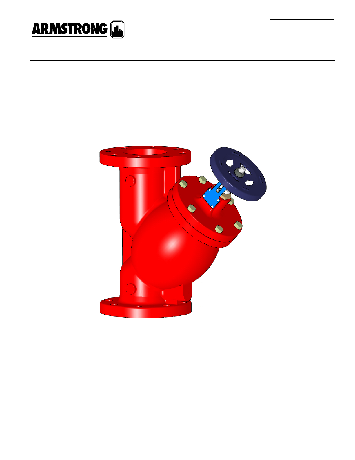
Armstrong Model FTV
350mm to 600mm
Flo-Trex Valve
FILE NO: 35.815IN
DATE: Aug. 25, 2011
SUPERSEDES: New
DATE: New
TABLE OF CONTENTS
Section Page
1.0 - Introduction.............................................................................................................................................2
1.1 - Warning ..................................................................................................................................................2
2.0 - Installation ..............................................................................................................................................3
3.0 - Storage...................................................................................................................................................3
4.0 - Cleaning .................................................................................................................................................3
5.0 - Maintenance...........................................................................................................................................3
6.0 - Disassembly & Assembly .......................................................................................................................4
Page 1 of 4
Page 2

1.0 - INTRODUCTION
The Armstrong Model FTV Flo-Trex Combination Valves are designed for installation on the discharge side of
centrifugal pumps. The Armstrong Combination Valve incorporates three functions in one valve:
• Drip-tight shut-off valve
• Spring-closure design, non-slam check valve
• Flow throttling valve
1. Body
2. Cover
3. Valve Seat
4. Disc
5. Disc Holder
6. Lower Stem
7. Upper Stem
8. Spring
9. Guide Bushing
10. Handle
1.1 - WARNING
These instructions must be read, understood and followed before attempting to install, maintain or operate this
equipment. Otherwise severe personal injury or damage to equipment may result.
Before installing the Flo-Trex valve, make sure that there is enough room provided to disassemble the valve
for maintenance.
Before undertaking any maintenance on the Flo-Trex valve, it must be isolated from the system line and any
pressure must be allowed to normalize to atmosphere.
Valves that remain in one position for long periods of times may be subject to some degree of reduced
operability as a result of loss of effective lubricants in threads, aging of gasket, surface corrosion of moving
parts, or accumulation of foreign solids. Refer to this manual’s recommended maintenance section to maintain
valve performance.
2.0 - INSTALLATION
The valve should be mounted to a spool piece on the discharge side of the pump. Spool piece length is based
on a minimum recommended space of 2 times the pipe diameter (e.g.: 350mm discharge requires 350mm D x
711mm L spool piece).
Page 2 of 4
Page 3

It is not recommended to mount a valve directly to the pump as this could cause undesirable noise in
the system.
Sufficient clearance around the valve should be left for valve removal or repair.
Install valve in the direction of the flow arrows on the valve body.
The valve body has been designed to handle the weight of the pump on vertical in-line installations. The body
is not designed to support the piping weight. It is recommended that the piping be supported by hangers. Pipe
supports should be provided under the valve and strainer bodies.
Ensure that the Flo-Trex is installed with the valve stem in the upright position. Valve slam may occur if
installed in any other configuration.
3.0 - STORAGE
The Flo-Trex valve must be examined for signs of damage that may have occurred during transportation.
The Flo-Trex valve should be stored in a suitably sheltered environment to protect it from the effects of
weather, dust, dirt, and moisture.
The Flo-Trex valve is shipped with end caps on the inlet and outlet ends. These end caps should be left in
place until it is ready for installation.
The Flo-Trex valve should be stored at a constant temperature between -10°C to 40°C (14°F to 104°F).
4.0 - CLEANING
The Flo-Trex valve has been cleaned, inspected, and sealed at the factory prior to shipment. The protective
end caps will guard against entry of foreign matter and no additional cleaning should be required. A visual
examination of the interior of the body should be made to ensure that the Flo-Trex valve is free of contaminants.
5.0 - MAINTENANCE
The Flo-Trex valve requires inspection and periodic maintenance at regular intervals to maintain optimum valve
performance and prolong equipment life.
The troubleshooting chart presented in the following table lists typical problems and methods for resolving
them. It should be noted that this chart does not present all possible problems or all possible solutions.
Problem Possible Cause Solution
Leakage
• Disc may fail to seat
(Foreign material lodged in orifice)
• Valve installed backwards
• Disassemble and clean
• Re-install in the direction of the
flow arrows
Pump overloading
Water hammer
• Valve may be closed or slightly opened
• Incorrect selection of valve size
• Buckling of stem. Foreign material lodged
in stem etc.
• Damage of the disc or seat
• Fully open the valve
• Re-size the valve
• Disassemble and check the stem
• Disassemble and check the disc
and seat
Page 3 of 4
Page 4

6.0 - DISASSEMBLY & ASSEMBLY
General: Before beginning to disassemble the Flo-Trex valve, become fully familiar with the construction
details and disassembly and re-assembly instructions prior to beginning any work.
Before undertaking any maintenance on the Flo-Trex valve it must be isolated from the system and any
pressure must be allowed to safely normalize to atmosphere.
To ensure that the Flo-Trex valve is re-assembled properly, it is necessary to mark certain parts and measure
and record certain dimensions. Additionally, ensure that spare and replacement parts such as o-rings,
gaskets, etc. are on hand before beginning the disassembly procedure.
6.1 - DISASSEMBLY
CAUTION: The Flo-Trex valve must be isolated from the system line and any pressure must be allowed
to normalize to atmosphere.
Remove handle by disengaging lock-nut from the stem.
Disassemble the travel indicator by removing the snap ring.
Unscrew guide bushing (The o-ring / gasket must be thoroughly cleaned. If there are any indications of
wear and/or scratches, they must be replaced.)
Release hex bolts and turn anti-clockwise until spring is slack.
Disassemble the cover, upper stem, spring and gasket. (The upper and lower stem, seat and disc must
be thoroughly cleaned. If there are any indications of bending, wear and/or scratches, they must
be replaced.)
When disassembling the disc assembly (disc holder, disc, lower stem) carefully lift the stem assembly
straight out of the body in order to avoid causing unnecessary damage.
If there is no damage to the seating surface, do not disassemble the seat.
6.2 - ASSEMBLY
Prior to assembly, be sure that all parts are clean and reassemble in reverse order of the disassembly.
Check to see that flange gaskets are properly positioned before tightening the bolts.
Tighten bolts gradually in a back and forth clockwise rotation.
Gradually adjust the stem until the proper flow rate is reached.
S. A. Arms
23 Bertrand Avenue
Toronto, Ontario
Canada, M1L 2
T: 416-755-2
F: 416-759-9
trong Limited Armstrong Integrated Limited Armstrong Design Private Ltd.
Manchester 490-L, 4th Phase, Peenya Industrial Area,
P3 United Kingdom, M12 5JL Bangalore, India 560 058
291 T: +44 (0) 8444 145 145 T: +91(80) 4906 3555
101 F: +44 (0) 8444 145 146 F: +91(80) 2334 3535
For Armstrong locations worldwide, please visit www.armstrongintegrated.com
Wenlock Way (Unit 1 - Armstrong Manufacturing Center)
© S.A. Armstrong Limited 2011
Page 4 of 4
 Loading...