

Armstrong FLO-RITE-TEMP 8120, FLO-RITE-TEMP 415, FLO-RITE-TEMP 415DW, FLO-RITE-TEMP 535DW, FLO-RITE-TEMP 665DW Installation And Adjustment Instructions
...
Bulletin No. AY-780-K
FLO-RITE-TEMP
INSTANTANEOUS WATER HEATER
INSTALLATION AND ADJUSTMENT INSTRUCTIONS
FOR SINGLE AND DOUBLE WALL UNITS
This bulletin should be used by experienced personnel as a guide to the installation of the
FLO-RITE-TEMP Instantaneous Water heater. Selection or installation of equipment should always
be accompanied by competent technical assistance. You are encouraged to contact Armstrong
International, Inc. or its local sales representative for additional information.

FLO-RITE-TEMP
INSTANTANEOUS WATER HEATER
INSTALLATION AND ADJUSTMENT INSTRUCTIONS
NOTICE
No water heater will work satisfactorily if improperly installed and operated. These instructions contain
important information for the installation and adjustment of the FLO-RITE-TEMP Water Heaters. Read
these instructions carefully before installing this unit. FAILURE TO ADHERE TO THESE
INSTRUCTIONS COULD RESULT IN SERIOUS BODILY INJURY OR PROPERTY DAMAGE.
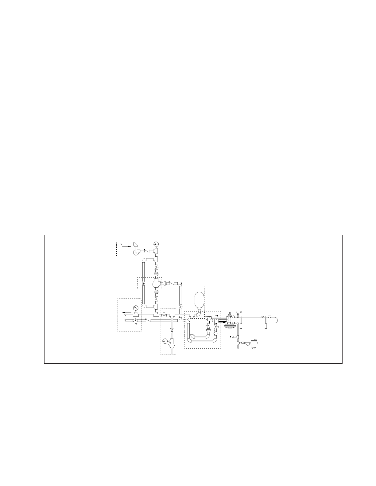
STEAM PIPING INSTALLATION OF A SINGLE UNIT
Single and Double Wall
Steam
In
Armstrong Pressure
Reducing Valve (If Req'd)
Armstrong
I.B. Trap
Armstrong Thermostatic
GP-2000
Air Vent
2-15 psig Steam
in the Shell
Vacuum Breaker
Pressure
Gauge
Gate
Valve
Safety Relief
Valve
Armstrong
I.B. Trap
NOTE: FLO-RITE TEMP is provided with (1) one Armstrong Steam Trap and Thermostatic
Air Vent (shaded). All other items shown not included.
Fig. 2-1
NOTE: units may be piped in parallel for larger capacity requirements. See Fig. 15-1 for an example of
parallel unit installation.
The unit includes the mixing valve mounted to the heat exchanger, channel iron and U-bolts mounted,
thermostatic air vent installed on the heat exchanger, a water pressure pop off valve integral to the unit control
valve and a separate Armstrong Inverted Bucket Steam Trap.
STEAM SIDE INSTALLATION
(Refer to Fig. 2-1)
1. Install the FLO-RITE-TEMP with adequate room to allow for tube bundle removal when cleaning is
required. See Table 12-1 for specific dimensions.
2. If 2-15 psig of steam is available a pressure reducing valve is NOT required. If a pressure reducing valve is
required, an Armstrong Inverted Bucket Steam Trap is recommended to drain condensate at the inlet of the
pressure reducing valve.
October 31, 2002 @ 3:15 pm
2
3. An Armstrong Y-strainer should be installed
before the pressure reducing valve to reduce the
chance of dirt fouling.
4. If an externally piloted pressure reducing valve is
used, the control pipe should be pitched away
from the PRV and installed at the pressure gauge
on the shell of the heat exchanger.
5. A steam safety relief valve should be used prior to
the heat exchanger if either or both of the
following conditions exist. (1) If the maximum
steam pressure could exceed the minimum water
pressure in the tubes, or (2) The maximum steam
pressure could exceed 150 psig (the maximum
steam pressure rating of the shell).
IMPORTANT -Steam supply pipe size
coming to the heat exchanger should NOT be
smaller than the steam connection supplied on
the heater, otherwise steam flow could be
restricted. If a pressure reducing valve is used,
installation should be as close as possible to the
Flo-Rite-Temp. Downstream piping from the
Pressure Reducing Valve should be expanded
immediately after the PRV to accomodate the
expanded volume of steam.
6. To vent start-up air, an Armstrong Thermostatic
Air Vent is included and installed on the top
connection, opposite the trap drain connection of
the heat exchanger. This discharge can be piped
to drain or the floor if preferred.
7. Install a vacuum breaker in the piping between the
heat exchanger drain connection and the steam
trap. This will prevent improper draining of the
heat exchanger caused by a possible vacuum
forming when the steam is shut off.
8. Install a suitable steam pressure gauge in the 1/4"
coupler located in the top mid section of the heat
exchanger shell. This gauge will help diagnose
pressure problems should they occur. This port
may also be used for a PRV external control pipe
if a PRV is required.
WATER PIPING INSTALLATION
(Follow same plumbing for DW units)
D
A
C
E
B
C
B
1. An 18 inch minimum thermal loop should be piped into the water inlet and outlet of the FLO-RITE-TEMP
and should be located as close to the mixing valve as possible (See Fig. 3-1A). These loops will act as a
thermal check valve or heat trap to prevent the conduction of heat through the water from the unit during
inactive times.
F
A
Fig. 3-1
2. Isolation valves and hose connections added to both the inlet and outlet water supplies will allow for
Clean-In-Place equipment to be utilized.
3. Use pipe unions on both the water inlet and outlet to allow ease of water heater mixing valve removal for
maintenance and removal of the tube bundle for cleaning (See Fig. 3-1A).
4. For adjusting the unit, an isolation valve and hot water by-pass to drain should be installed close to the unit
October 31, 2002 @ 3:15 pm
3
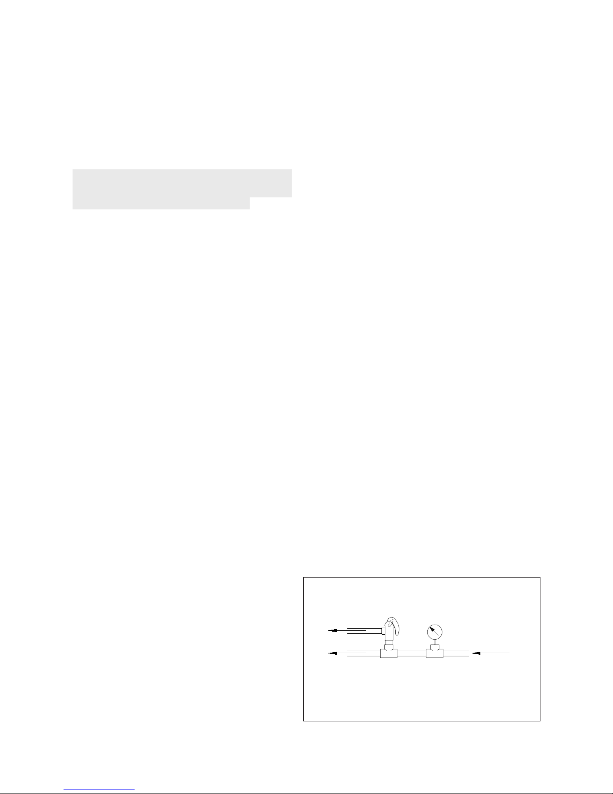
down stream from the thermal loops and prior to
the recirculation loop (if one is used) (See Fig.
3-1B). This allows for quick and easy setting of
the FLO-RITE-TEMP by one person. By isolating
the unit from the hot water system, flow can be
controlled to drain through the globe valve while
monitoring outlet water temperature during low
and high flow adjustments on the water heaters
mixing valve.
Minimum line sizes to drain should be as
follows: model 415 = 3/4", model 535 = 1",
model 665 = 1-1/4", model 8120 = 2". Line
sizes smaller than these will not allow sufficient
flow for making high flow settings on the mixing
valve.
5. A water temperature gauge should be installed
directly after the by-pass drain valve. This
thermometer is only used for inital temperature
adjustments of the Flo-Rite-Temp or
troubleshooting the unit. (See Fig. 3-1B)
6. If a recirculation system is used with a
FLO-RITE-TEMP, a small diverting valve must
be piped into the loop return downstream of the
recirculating pump (See Fig. 3-1C). This device is
used to divert recirculated water back to the
heater for reheating if the temperature of the
water drops too low due to no hot water demand
from the system plus piping radiation losses (See
page 9 for operation explanation). Be sure to pipe
in unions and isolation valves to facilitate diverting
valve removal required when element replacement
is needed. A throttling type valve should be
installed in a full return line size bypass around the
diverting valve in order to balance the flow to the
diverting valve. This is especially needed when
recirculating pumps are large or oversized.
7. For a recirculated system, a small constant running
pump should be piped in on the return side of the
loop (See Fig.3-1D). This pump should be sized to
move approximately 10% of the maximum rated
gpm of the FLO-RITE-TEMP in the system with
enough head to overcome the head encountered in
the loop.
NOTE: A thermometer should be installed in
the outgoing loop to monitor system temperature
(Fig. 3-1E). A thermometer may also be
installed on the loop return to monitor
temperature drop through the loop or to help
troubleshoot the diverting valve (Fig. 3-1D). The
thermometer referred to in point #4 and Fig. 3-1B
should only be used to set the FLO-RITE-TEMP
and never used to monitor system temperature.
NOTE: Expansion tanks should be used in on/
off demand applications where there is a short
duration of time from high flow to no flow of
water, i.e., a shut off time of 10 seconds or less.
(See Fig. 3-1F)
OPTIONAL SAFETY EQUIPMENT
See Fig. 3-1E for location of each option within the system. All options would be installed downstream of
the water heater in the outgoing recirculation loop, if one is present, or downstream of the hot water thermal
loop if recirculation is not used but always before the first hot water take off from the system.
Option #1 A temperature relief valve set at roughly 15-30 degrees above that of the FLO-RITE-TEMP
will help prevent any chance of overheated water reaching the faucets. (NOTE: Normally unit will fail closed
and either no water or only cold water will flow from the unit.)
Option #2 A 3-way blending valve with a set
point 10-30 degrees above that of the FLO-RITETEMP will help prevent the chance of overheated
water reaching the faucets in the event of unit failure.
Under normal operating conditions the hot water flows
straight through the blending valve from Port B to Port
A. But in the event of an overheated situation, the
blending valve will open Port C to add sufficient cold
water to maintain a constant temperature . (NOTE:
The blending valve should be sized to handle the
maximum flow of the system).
October 31, 2002 @ 3:15 pm
Temperature
Relief Valve
Option #1
4
Loop or System
Thermometer
Hot Water from
Flo-Rite-Temp
3-Way
Thermostatic
Valve
Loop or System
Thermometer
To Flo-Rite-Temp
Cold Water Supply
Option 3A
Temperature
Switch
Hot Water from
Flo-Rite-Temp
Option 3B
Pressure Switch
Loop or System
Thermometer
To steam
shut-off valve
Option #3Option #2
Hot Water Supply From
Flo-Rite-Temp
To Steam
Shut-Off Valve
!
Cold Water Supply to
Flo-Rite-Temp
Option #3 A temperature switch installed well downstream of the Flo-Rite-Temp outlet on a non-recirculated
system or just into the outgoing recirculated system loop on a recirculated system, with a set point 15-30
degrees above that of the FLO-RITE-TEMP will help prevent the chance of overheated water reaching the
faucets in the event of system problems. This switch can be used to turn off the steam supply to the heater in
the event of overheating. The most economical way to accomplish this is with a solenoid on the PRV. A full
ported motorized valve on the steam supply line may also be used. Option 3B. Along these same lines, a
pressure switch installed in the inlet water line would shut down the supply steam on the heat exchanger in the
event of water pressure loss, preventing thermal shock and water hammer to the unit.
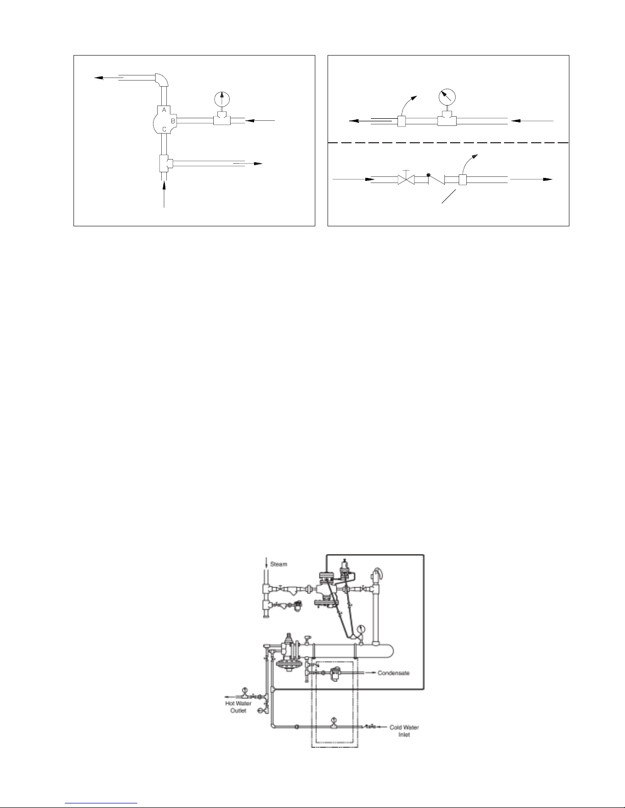
Option #4 (Available only when a pressure reducing station is installed on the Flo-Rite-Temp). Using the
Model GP-2000W1P system, when piped as shown in the Option 4 drawing, will provide a safe dependable
shut down of the main steam valve when the water pressure fails or drops rapidly on the Flo-Rite-Temp.
Unlike a solenoid application, which shuts the steam down when the water pressure drops below a pre-set
point, the GP-2000W1P offers another benefit that it allows the system to keep producing hot water even
when the water pressure is below the set pressure. The GP-2000W1P Combination valve essentially lets the
steam pressure modulate below the water pressure by 2 or 3 pounds, allowing a water heater to supply hot
water even when water pressure is low.
Incoming cold water is piped into the hot water heater with a sample line piped to the W-1 Pilot of
GP-2000W1P. At the same time the cold water is supplying the water heater, its pressure it is also supplying
the W-1 Pilot. When the pressure of the incoming cold water decreases, the W-1 Pilot modulates down the
supply of steam to the pressure pilot controlling the main steam valve, acting as a non-electric self-controlled
shutdown device. Ultimately, this valve eliminates the use of any electricity and gives the customer safe
control of their hot water supply when water pressure loss or fluctuating water pressure conditions exist.
October 31, 2002 @ 3:15 pm
Option #4
5
 Loading...