

Armstrong ASTRO 220SSU075S-TA, ASTRO 225BS050S-TA, ASTRO 220SSU050S-TA, ASTRO 225BS075S-TA, ASTRO 225SSU-TA Installation And Operating Instructions Manual
...
ASTRO 2 SERIES HOT WATER RE-CIRCULATION
SYSTEM
INSTALLATION AND OPERATING INSTRUCTIONS
|
File No: 10.812
Date: july 23, 2015
Supersedes: 10.812
Date: july 09, 2015
1.0 Typical application 1
2.0 How it works 1
3.0 Technical data 1
4.0 Installation 2
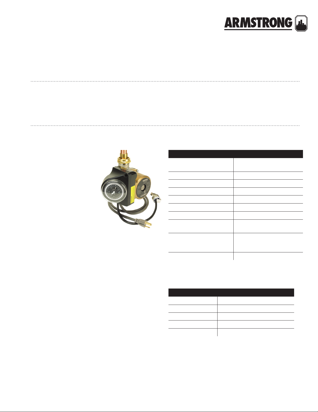
1.0 typical applications
Armstrong Astro 2 Hot water
re-circulation systems automatically circulate water
through domestic hot water
distribution pipes. This helps
to ensure that everyone in the
household has “instant” hot water at the tap when they need it,
while also helping to conserve
water and save water heating
energy costs. All systems are
assembled, wired, tested, and
then shipped from the factory,
ready for installation.
2.0 how it works
5.0 Operation 4
6.0 Setting the clock/timer 5
7.0 Replacement parts 5
3.0 technical data
technical data
Power Connection
Environment Indoor use only
Max. working pressure 150 psi (1034 kPa)
Ambient temperature 39°f (4°c) to 104°f (40°c)
Max. water temperature 230°f (110°c)
Low temperature switchpoint
High temperature switchpoint
Clock/timer
Timer settings
Manual override 3 position slide switch; on/auto/o
6.0 ft (1.8 m) power cord, molded
duplex plug with ground
1
85°f (29°c) ±10%
1
105°f (40°c) ±10%
12-hour analog clock with am/pm
indication
Individual mechanical toggles
for each 15 minute interval over
24 hours
In normal operation, the Astro 2 automatically starts recirculating water throughout the hot water distribution system
whenever the timer enables activation. The timer can be set for
one or more activation periods per day. An activation period
consists of a multiple (up to 96) of 15 minute time intervals. The
timer includes manual on and o overrides to normal
automatic operation.
Some models are equipped with an Aquastat, intended for
use on metallic piping. The Aquastat enables operation only
when the sensed water temperature is below 85°f (25°c). Once
activated, the circulator operates until either the water temperature reaches 105°f (41°c), or the current timed activation
period ends.
1
High/low temperature switch points are as measured on pipe surface
with the Aquastat (-ta mode ls only).
materials of construction (wetted parts)
Pump casing Lead free bronze* or Stainless steel*
Pump shaft Ceramic
Impeller Noryl
Bearings Ceramic
Bearing seal epdm
*Certified to nsf-372 Complies with section 116875 of the California Health
and Safety Code and Vermont Act 193 (Lead content of wetted surface is
0.25% or less.)
installation &
operating instructions
Astro 2 series
Hot water re-circulation system
2
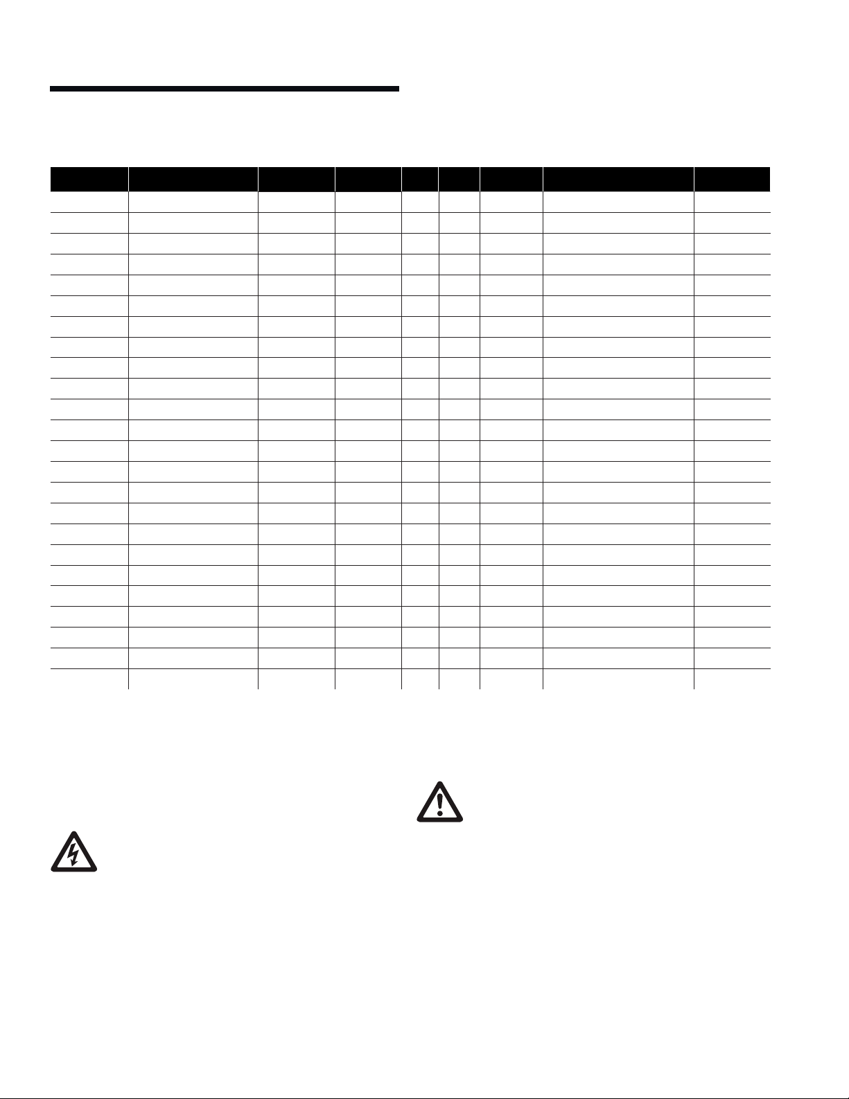
item model connection size cord timer aquastat electrical data weight
110223b -140
110223b -141
110223b -142
110223b-143 astro 225bs075s-ta Sweat ¾"
110223b-144 astro 220ssu-ta npsm union 1¼"
110223b-145 astro 225ssu-ta npsm union 1¼"
110223b-148 astro 2 3 0ss-ta 2 bolt flange 2 bolt flange
110223b-149 astro 250ss-ta 2 bolt flange 2 bolt flange
110223b-240 astro 220ssu050s-t* Sweat ½"
110223b-241 astro 220ssu075s-t* Sweat ¾"
110223b-242 astro 225bs050s-t Sweat ½"
110223b-243 astro 225bs075s-t Sweat ¾"
110223b-244 astro 220ssu-t npsm union 1¼"
110223b-245 astro 225ssu-t npsm union 1¼"
110223b-248 astro 2 30ss-t 2 bolt flange 2 bolt flange
110223b-249 astro 250ss-t 2 bolt flange 2 bolt flange
110223-340 astro 220ssu050s-lc* Sweat ½"
110223-341 astro 220ssu075s-lc* Sweat ¾"
110223-342 astro 225bs050s-lc Sweat ½"
110223-343 astro 225bs075s-lc Sweat ¾"
110223-344 astro 220ssu-lc npsm union 1¼"
110223-345 astro 225ssu-lc npsm union 1¼"
110223-348 astro 230ss-lc 2 bolt flange 2 bolt flange
110223-349 astro 250ss-lc 2 bolt flange 2 bolt flange
astro 220ssu050s-ta*
astro 220ssu075s-ta*
astro 225bs050s-ta
Sweat ½"
Sweat ¾"
Sweat ½"
ü ü ü
ü ü ü
ü ü ü
ü ü ü
ü ü ü
ü ü ü
ü ü ü
ü ü ü
ü ü
ü ü
ü ü
ü ü
ü ü
ü ü
ü ü
ü ü
ü
— — 115 Vac , 60 Hz, 0.29 A, 33W 7.0 0 (3.18)
ü
— — 115 Vac , 60 Hz, 0.29 A, 33W 7.0 0 (3.18)
ü
— — 115 Vac , 60 Hz, 0.64 A, 75W 6. 50 (2.95)
ü
— — 115 Vac , 60 Hz, 0.64 A, 75W 6. 50 (2.95)
ü
— — 115 Vac , 60 Hz, 0.29 A, 33W 7.0 0 (3.18)
ü
— — 115 Vac , 60 Hz, 0.69 A, 83W 7.00 (3.18)
ü
— — 115 Vac , 60 Hz, 0.81 A, 97W 9.00 (4.08)
ü
— — 115 Vac , 60 Hz, 0.9 8 A, 117W 9.00 (4.08)
115 Vac , 60 Hz, 0.29 A, 33W 7.50 (3.4 0)
115 Vac , 60 Hz, 0.29 A, 33W 7.50 (3.4 0)
115 Vac , 60 Hz, 0.64 A, 75W 7.0 0 (3 .18 )
115 Vac , 60 Hz, 0.64 A, 75W 7.0 0 (3 .18 )
115 Vac , 60 Hz, 0.29 A, 33W 7.50 (3.4 0)
115 Vac , 60 Hz, 0.69 A, 83W 7.50 (3.4 0)
115 Vac , 60 Hz, 0.81 A, 97W 10. 0 0 (4. 54)
115 Vac , 60 Hz, 0.9 8 A, 117W 10.0 0 (4. 54)
— 115 Vac , 60 Hz, 0.29 A, 33W 7.50 (3.4 0)
— 115 Vac , 60 Hz, 0.29 A, 33W 7.50 (3.4 0)
— 115 Vac , 60 Hz, 0.64 A, 75W 7.0 0 (3 .18 )
— 115 Vac , 60 Hz, 0.64 A, 75W 7.0 0 (3 .18 )
— 115 Vac , 60 Hz, 0.29 A, 33W 7.50 (3.4 0)
— 115 Vac , 60 Hz, 0.69 A, 83W 7.50 (3.4 0)
— 115 Vac , 60 Hz, 0.81 A, 97W 10. 0 0 (4. 54)
— 115 Vac , 60 Hz, 0.9 8 A, 117W 10.0 0 (4. 54)
note: All weights are in lbs. (kg) *Union model with sweat hardware kit.
4.0 installation
warning
• Installationshouldonlybecompletedbyqualied
personnel, in accordance with all applicable codes,
and following generally accepted installation
practices.
• Ensurethehotwatersupplyisturnedobefore
installation, to avoid personal injury or damage
to property.
• Readandunderstandtheseinstructionsthoroughly before beginning the installation.
cautio n
Prior to installation, flush all piping of any foreign material to prevent pump blockage and prevent damage.
procedure
1 Timer installation and wiring
Note: Numerical component designations included in Steps i
through viii refer to circulator and timer components shown
in fig. 1. Steps 1 & 3 apply to retrofit installations.
i Disconnect the electrical supply to the circulator
ii Unfasten the mounting 2 screws 4 and remove the
terminal box cover 3.
iii Disconnect wire leads from the power supply.

timer
cold water
iv Connect power supply wires (black, white and green) to
the timer unit and to the circulator terminals (as shown
in fig.2). Note: Lead Wiring Specification - Minimum,
6" (152 mm) long, 14 awg, rated minimum 140°f (60°c).
Provided with r/c crimp connectors for attachment to
the ground.
v Place the timer box cover 5 using the 2 mounting
screws 4. Insure that all lead wires are inside the timer
assembly.
vi Program the timer according to instructions provided
on page 5
vii Connect the unit to electrical supply.
viii Start the circulator
Assembly - Exploded Layout
44
6
3
5
2
1
1 Pump 4 Mounting screw
2 Terminal box base 5 Timer box cover
3 Terminal box cover 6 Timer module cover
fig. 1 Astro 2 Series circulator and 24-Hour Timer assembly
drawing
timer
black
black
white
green
fig. 2 Astro 2 Series circulator and 24-Hour Timer wiring
diagram
black
black
white
green
white
black
Astro 2 series
Hot water re-circulation system
black
black
black
white
white
aquastat
black
white
green
white
black
operating instructions
installation &
fig. 3 Astro 2 Series circulator and 24-Hour Timer and
Aquastat Control wiring diagram
2 Select a suitable location for system installation. Typically,
the Astro system is mounted near the hot water heater. The
inlet is connected to a return line from the furthest hot water
tap in the system. The discharge is connected into the hot
water heater drain line.
3 Ensure the following conditions are met when the system
is mounted:
i The circulator shaft is horizontal.
ii The clock/timer face is accessible for viewing
and adjustment.
iii The direction of water flow matches the arrow on the
circulator casing.
iv The piping is suciently rigid to support the system
in operation.
v Neither the clock/timer nor black terminal box is under
the circulator.
4 The Astro system is shipped fully assembled and tested to
suit either down discharge orientation with the clock timer
facing up, or horizontal discharge with the clock timer facing
the water supply side. For alternate orientation, see Rotating
the circulator casing.
supply line
hot water
tank
hot water supply line
air vent (optional)
domestic hot
water return line
isolation valve
aquastat
timer
astro circulator
check valve
hose bib
(drain valve)
blow down valve
3

installation &
operating instructions
4
Astro 2 series
Hot water re-circulation system
timer/discharge orientation (as shipped)
top timer access,
down discharge
5 Connect the hot water return line to the circulator, verifying
proper flow direction.
6 Attach the Aquastat by the integral spring clip, to either
the circulator inlet or discharge piping, whichever is most
convenient. Ensure the concave sensor face of the Aquastat
remains in direct contact with the pipe surface.
7 Supply water to the system and inspect connections and
components for leaks.
8 In order to purge the air from the recirculation line:
i Make sure that the system is connected to the cold water
line and no fixtures are in use in the building.
ii Close the blow down valve.
iii Open the drain valve. Wait until all the air is purged from
the system and the water flow is steady through
the drain valve.
iv Close the drain valve.
Vent the circulator to remove trapped air:
v Place a one gallon or larger container under the circulator.
vi Loosen the brass plug in the end of the circulator with a
slotted screwdriver until water just begins to run out into
the container.
vii When the vented water is free of air bubbles, gently
retighten the brass plug until sealed.
viii Open the blow down valve.
The system is purged by air and ready for operation.
9 Verify that the timer’s manual override switch is in the
o position.
10 Plug the power cord into a standard 115 V ac electrical
receptacle.
side timer access,
horizontal discharge
11 To perform an initial system test for basic operation, see
Operation.
rotating the circulator casing
Prior to connecting the system to the hot water piping, if alternate orientation of either the circulator discharge or clock timer
is required, proceed as follows:
1 Remove the four hex socket head screws that hold the cas-
ing to the circulator.
2 Gently pull the casing from the circulator body, taking care
not to damage the gasket or impeller.
3 Rotate the casing as required to meet circulator discharge
and clock timer orientation requirements.
4 Tighten the four hex socket head screws evenly, ensuring the
gasket seals the mating surfaces.
5 To verify the circulator shaft still spins freely:
i Remove the plug from the end of circulator with a slotted
screwdriver.
ii Insert the screwdriver in the slot in the end of the shaft.
iii Ensure the shaft turns freely and smoothly in both
directions.
iv Replace the plug and gently tighten.
5.0 operation
cautio n
Never operate the system 'dry' or permanent damage may occur to the circulator. Never shut o the
water supply or restrict flow in any way while the
circulator is operating.
1 Verify water is present at the circulator.
2 Verify the power cord is plugged into an appropriate house-
hold electrical receptacle.
3 To continuously run the circulator or test for initial operation,
set the manual override switch to the on position and verify
the circulator operates smoothly and quietly.
4 To prevent circulator operation, such as for extended periods
that the residence will be V acated, set the manual over ride
switch to the o position.
5 For normal automatic operation, set the clock/timer as
required and move the manual override switch to the
auto position.

Astro 2 series
o
on
auto
Hot water re-circulation system
installation &
operating instructions
5
manual override switch positions
6.0 setting the clock/timer
1 Rotate the dial in a clockwise direction until both the time
shown, and the appropriate am or pm indicator, correspond
to the current time of day. (This adjustment is required for
initial operation, following a power interruption, to adjust for
daylight savings time, or for periodic time correction.)
2 Remove the clear plastic cover from the dial.
3 The outer ring of the dial has an adjustable tab for each 15
minute time interval of a 24 hour day. To enable circulator
operation for a specific time interval, slide the corresponding interval tab toward the perimeter of the dial. All tabs
positioned toward the center of the dial disable circulator
operation for those time intervals.
4 Verify the manual override switch is in the auto position.
5 Replace the clear plastic cover on the dial.
7.0 replacement parts
astro models (pump only) item number
Astro 220ssu w/ ½" swt 110223-301
Astro 220ssu w/ ¾" swt 110223-302
Astro 225bs ½" swt 110223-303
Astro 225bs ¾" swt 110223-304
Astro 230ss 110223-306
Astro 250ss 110223-308
Astro 220ssu 110223-309
Astro 225ssu 110223-310
part description item number
24-Hour timer 810223-130
Timer cover 110223-041
½" Aquastat 110123-120
¾" Aquastat 110123-121
current time
interval tabs
(15 minutes each)
manual override
dial
am/pm indicators

toronto
23 bertrand avenue
toronto, ontario
canada
m1l 2p3
+1 416 755 2291
buffalo
93 east avenue
north tonawanda, new york
u.s.a.
14120-6594
+1 716 693 8813
birmingham
heywood wharf, mucklow hill
halesowen, west midlands
united kingdom
b62 8dj
+44 (0) 84 44 145 145
manchester
wolverton street
manchester
united kingdom
m11 2et
+44 (0) 84 44 145 145
bangalore
#59, first floor, 3rd main
margosa road, malleswaram
bangalore, india
560 003
+91 (0) 80 4906 3555
shanghai
no. 1619 hu hang road, xi du township
feng xian district, shanghai
p.r .c .
201401
+86 21 3756 6696
armstrong fluid technology
established 1934
armstrongfluidtechnology.com
tm
 Loading...