

Page 1

Date: 10/01/07
OWNERS MANUAL
CUMMINS SERIES:
MODELS A50CU, A75CU, A05CU, A200CU, A300CU, A400CU,
A500CU, A600CU, A830CU, A1000CU
SAVE THESE INSTRUCTIONS
This manual contains important instructions regarding for all
Armstrong Power Systems LLC power generator Models. The
information contained here must be followed during installation
and maintenance of the generator and batteries. Keep this
AR-EXP-CUMMINS-07-00 OWNERS MANUAL
Page 2

Page 2
SAVE THESE INSTRUCTIONS
This manual contains important instructions regarding for all Armstrong
Power Systems LLC power generator Models. The information contained
here must be followed during installation and maintenance of the generator and batteries. Keep this manual with the equipment. If the equipment
is traded or sold, give the manual to the new owner.
You are now the owner of a Armstrong Power generator powered by
CUMMINS engine. All our components keep the highest standards in
quality, efficiency and durability.
Each unit pass thru a complete test and inspection to guarantee the
quality of your unit. We provide warranty on every component subject to
the warranty coverage and limitations.
To get the best results from your new generator please read carefully
this document before starting the unit and follow the instructions.
If you have any question regarding your equipment please call your
dealer or contact us. Please have the generator model, and serial numbers when you call. Parts may be obtained directly from our distributors.
Once again thank you for your trust in Armstrong Power and welcome to
our family.
AR-EXP-CUMMINS-07-00 OWNERS MANUAL
Page 3

The warranty period for the power generator begins on the date of sale and continues for a period of 2 years or 1500 hours (what ever comes first).
Responsibilities: a) As the owner, you are responsible for the performance of the required maintenance listed on your operators manual. b) Armstrong Power may
deny your warranty coverage if your engine or part has failed due to abuse, neglect, improper maintenance or unapproved modifications.
Coverage: Armstrong Power warrants that your unit shall be free from defects in materials and workmanship which cause the unit to fail. During the period mentioned
above from the date of the original sale.
Limitations: this warranty certificate shall not cover any of the following. a) Repair or replacement required because of misuse or neglect, improper maintenance,
repairs improperly performed or replacements not conforming to Armstrong Power specifications that adversely affect performan ce and/or durability, and alteration or
modifications not recommended or approved in writing by Armstrong Power. b) Replacement of parts and other services and adjustments necessary for required
maintenance at and after the first scheduled replacement point.
Page 3
WARRANTY CERTIFICATE
AR-EXP-CUMMINS-07-00 OWNERS MANUAL
Page 4
Page 4
AR-EXP-CUMMINS-07-00 OWNERS MANUAL
Page 5

Page 5
1. INTRODUCTION
This manual provides general safety information for installing, operating and maintenance of Armstrong Power
equipments. The purchaser should comply with the instructions and information in this manual, and is strongly advised that all personnel to be associated with the equipment supplied should be made familiar with the information
contained herein.
It is essential that the personnel engaged in the installation, commissioning and maintenance of this equipment are
both competent and experienced in these fields, and that they comply with the relevant statutory requirements and
regulations, including he provisions of the Health and Safety act 1974, and any such modifications and amendments
which may subsequently become a legal requirement.
The equipment supplied by Armstrong Power should be installed by, or under the supervision of, competent person-
nel in accordance with good engineering practice, established codes of practice, those statutory requirements applicable to the installation site, the IEE regulations as applicable and, where the appropriate, in accordance with any
instructions specifically advised by the company.
You are requested, in accordance with the needs of safe operation and the provisions of the act, to take such steps
as are necessary to ensure that the appropriate information on the proper use and handling of our equipment is
made available by yourself to all those concerned. Similarly, this information must be available to anyone who may
purchase, or otherwise acquire from your self, such products for use in their own premises.
2. GENERAL
The generating set is designed to be safe when used in the correct manner. The following safety precautions, if fol-
lowed will minimize the possibility of accidents. Before performing any procedure or operating technique, it is up to
the user to ensure that it‘s safe. The generating set should only be operated by personnel who are authorized and
trained.
Warning:
Read and understand all safety precautions, and warnings before operating the generating set.
Failure to follow the instructions, procedures and safety precautions in this manual may increase the possibility
of accidents and injuries.
Never start the generating set unless it is safe to do so.
Do not attempt to operate the generating set with a know unsafe condition.
If the generating set is unsafe, fit danger notices and disconnect the battery negative (-) lead so that it cannot
be started until the condition is corrected.
Disconnect the battery negative (-)lead prior to attempting any repairs or cleaning inside the enclosure, if
equipped.
Appropriate firefighting equipment is to hand.
The metal work on every part of the generating set must be connected by means of an earth continuity conduc-
tor to an effective earth point.
Care must be taken to avoid spillage from the batteries.
No loose items or combustible material should be left on or against any part of the generator.
Do not risk injury by coming into contact with moving parts of the plant, or by allowing anything to be draw in
by the cooling fan or intake system.
Install and operate this generating set only in full compliance with relevant National, local or federal codes,
standards or other requirements.
AR-EXP-CUMMINS-07-00 OWNERS MANUAL
Page 6
Page 6
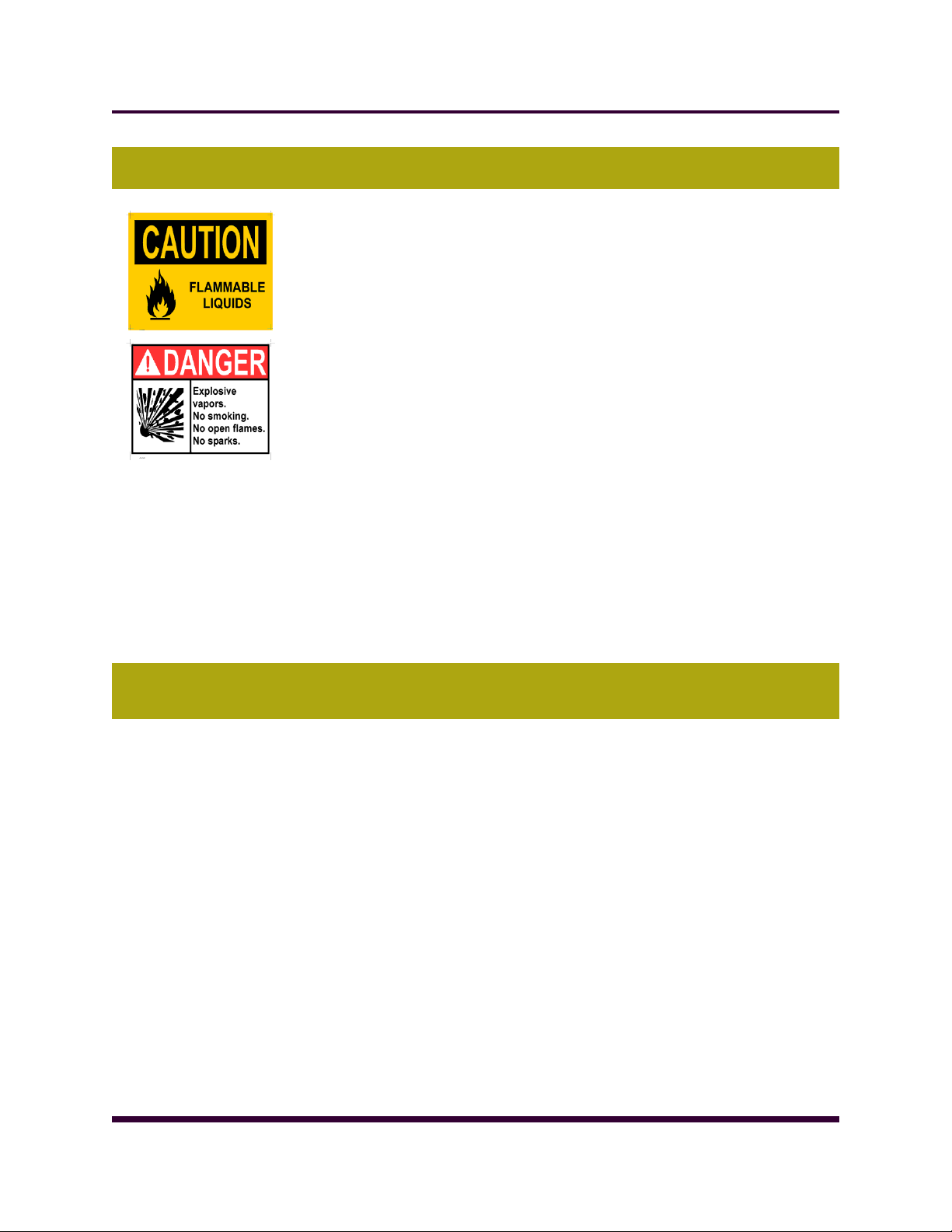
3. FIRE AND EXPLOSION
Risk of serious injuries or death
Don‘t touch the battery charger or the connections during the battery charging process.
Always disconnect the negative terminal from the battery before to start any work on the unit.
Keep the room, the floor and the generating set clean. When spills of fuel, oil, battery electrolyte or coolant occur
they should be cleaned up immediately.
Never store flammable liquids near the engine.
Store oily rags in covered metal containers.
Avoid refilling the fuel tank while the engine is running.
Do not attempt to operate the generating set with any known leaks in the fuel system.
Fuels and fumes associated with generating sets can be flammable and potentially explosive.
Proper care in handling these materials can dramatically limit the risk of fire or explosion.
However, safety dictates that fully charged BC and ABC fire extinguishers are kept on hand.
Personnel must know how to operate them.
The acids in the battery can cause explosion.
Avoid any contact between the tools and the terminals in the battery.
Never use metallic objects on the neck or hands when handling the set.
Never connect the negative terminal from the battery to the positive terminal from
the starter.
Don‘t smoke or allow sparks, flames or other sources of ignition around the fuel or bat-
teries.
Use adequate equipment to take fuel from the set.
Never test the battery by touching together the terminals.
Ensure the generating set room is properly ventilated.
4. INSTALLATION, HANDLING AND TOWING
Make electrical connections in compliance with relevant electrical codes, standards or other requirements. This in-
cludes requirements for grounding and ground/earth faults.
For stationary generating sets with remote fuel storage systems, make sure such systems are installed in compliance
with relevant codes, standards or other requirements.
Engine exhaust emissions are hazardous to personnel. The exhaust for all indoor generating sets must be piped out-
doors via leak-free piping in compliance with relevant codes, standards and other requirements. Ensure hot exhaust
silencers, piping and turbochargers, if equipped, are clear of combustible material and are guarded for personnel
protection per safety requirements. Ensure that fumes from the exhaust outlet will not be hazard.
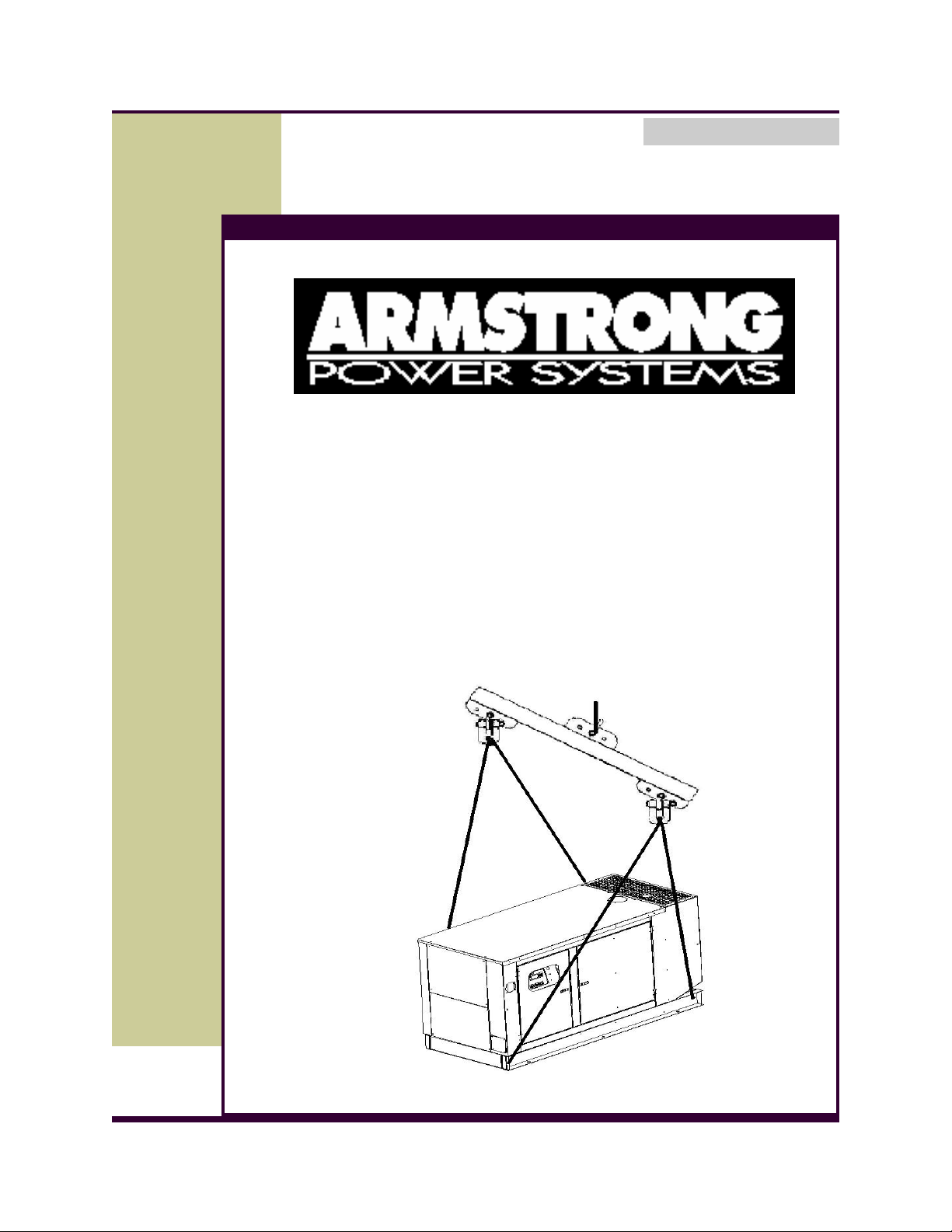
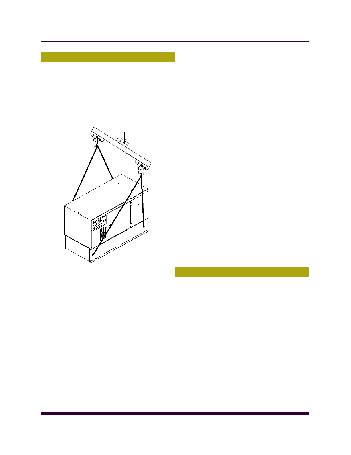
Never lift the generating set by attaching to the engine or alternator lifting lugs. Use a sling with a ―spreader bar‖
connected to the base frame.
Ensure the lifting rigging and supporting structure is in good condition and has capacity suitable for the load.
Keep all personnel away from the generating set when it is suspended.
Make sure all personnel are out of the generating set canopy or container, if equipped, before closing and latching
enclosure doors.
When towing a mobile generating set, observe all codes, standards or other regulations and traffic laws. These in-
clude those regulations specifying required equipment and maximum and minimum speeds. Ensure brakes, if fitted,
are in good order.
Do not permit personnel to ride in or on the mobile generating set. Do not permit personnel to stand or ride on the
drawbar or to stand or walk between the generating set and the towing vehicle.
Do not install or use the generating set in any classification of hazardous environment unless it has been specifically
designed for that environment.
AR-EXP-CUMMINS-07-00 OWNERS MANUAL
Page 7
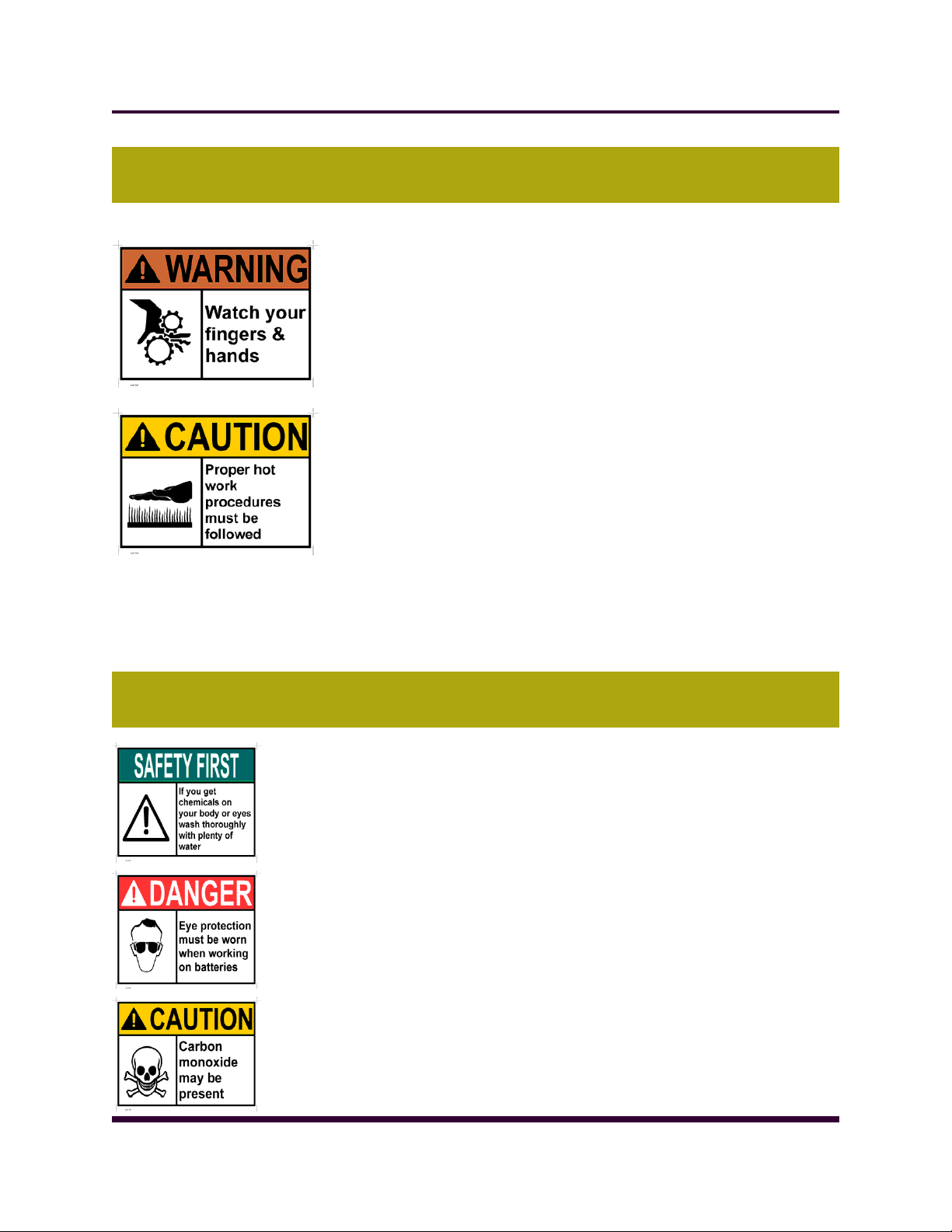
5. MECHANICAL
The generating set is designed with guards for protection from moving parts. Care
must still be taken to protect personnel and equipment from other mechanical
hazards when working around the generating set.
Do not attempt to operate the generating set with safety guards removed.
While the generating set is running do not attempt to reach under or
around the guards to do maintenance or for any other reason.
Keep hands, arms, long hair, loose clothing and jewellery away from pul-
leys, belts and other moving parts.
Attention!! Some moving parts con not be seen clearly when
the set is running.
Keep access doors on enclosures, if equipped, closed and locked when not
required to be open.
Avoid contact with hot oil, hot coolant, hot exhaust gases, hot surfaces and
sharp edges and corners.
Wear protective clotting including gloves and hat when working around the
generating set.
Do not attempt to remove the radiator filler cap until the coolant has cooled. Then loosen the cap slowly to relive
any excess pressure before removing the cap completely.
Ethyl ether starting aids must not be used on engines with combustion air preheating devises. These starting aids
will reduce the efficient working life of the engine.
6. CHEMICAL
Page 7
Fuels, oils coolants, lubricants and battery electrolyte used in this generating set
are typical of the industry. However they can be hazardous to personnel if not
treated properly.
Do not swallow or have skin contact with fuel, oil, coolant, lubricants and
battery electrolyte. If swallowed, seek medical treatment immediately. Do
not induce vomiting if fuel is swallowed. For skin contact, wash with soap
and water.
Do not wear clothe that has been contaminated by fuel or lube oil.
Wear an acid resistant apron and face shield or goggles when servicing
the battery. If electrolyte is spilled on skin or clotting, flush immediately
with large quantities of water.
Always keep good ventilation when the equipment is working. Carbon
Monoxide inhalation cause death. Always maintain inspection routine of
the exhaust system.
AR-EXP-CUMMINS-07-00 OWNERS MANUAL
Page 8

Page 8
7. NOISE
Generating sets that are not equipped with sound attenuating enclosures can produce
noise levels in excess of 105 dBA. Prolonged exposure to noise levels above 85 dBA is
hazardous to hearing.
Ear protection must be worn when operating or working around an operating
set.
8. ELECTRICAL
Safe and efficient operation of electrical equipment can be achieved only if the equipment is correctly installed, operated and maintained.
The generating set must be connected to the load only by trained and quali-
fied electricians who are authorized to do so, and in compliance with relevant electric codes, standards and other regulations.
Ensure the generating set, is effectively grounded/earthed in accordance
with all relevant regulations prior operation.
The generating sets should be shutdown with the battery negative (-) termi-
nal disconnected prior to attempting to connect or disconnect load connections.
Do not attempt to connect or disconnect load connections while standing in
water or on wet or soggy ground.
Do not touch electrical energized parts of the generating set and/or inter-
connecting cables or conductors with any part of the body or with any non
insulated conductive object.
Place the control panel cover as soon as connection or disconnection of the
load cables is complete. Do not operate the generating set without the
cover securely on place.
Connect the generating set only to loads and/or electrical systems that are com-
patible with it‘s electrical characteristics and that are within it‘s rated capacity.
Be sure all power is disconnected from the electrical equipment being serviced.
Keep all electrical equipment clean and dry. Replace any wiring where the insulation is cracked, cut, abraded or oth-
erwise degraded. Replace terminals that are worm, discolored or corrode. Keep terminals clean and tight.
Insulate all connections and disconnected wires.
Use only class BC or Class ABC extinguishers on electrical fires.
AR-EXP-CUMMINS-07-00 OWNERS MANUAL
Page 9
9. FIRST AID FOR ELECTRIC SHOCK
Identification / look out for:
Unconsciousness and Burns
Establish site of entry and exit of electric shock
What to do:
Switch off the main switch.
Break the contact between electrical source and patient using dry non-conductive object like wooden stick.
Call for help.
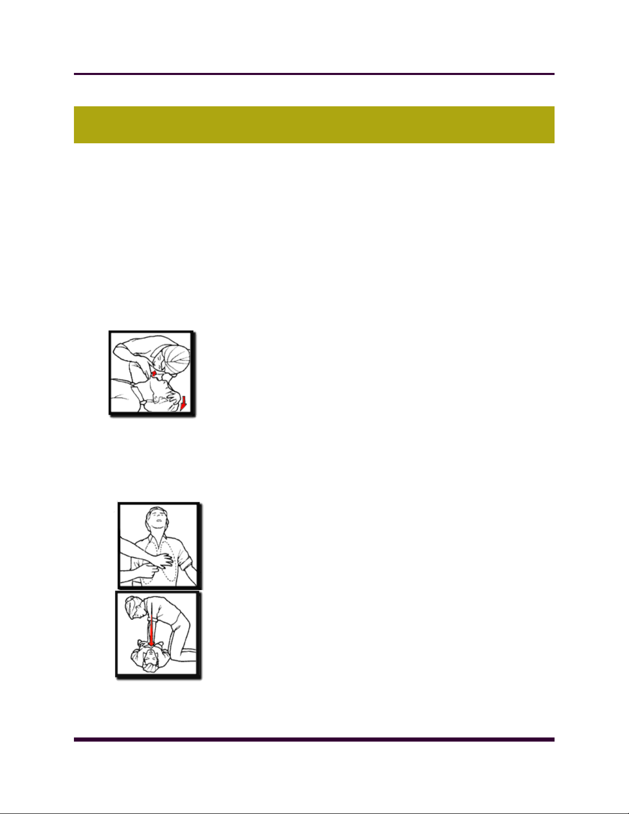
If breathing and heartbeat has stopped begin CPR
1. CALL
Check the victim for unresponsiveness. If there is no response, Call 911 and return to the victim. In most locations
the emergency dispatcher can assist you with CPR instructions.
2. BLOW
3. PUMP
Tilt the head back and listen for breathing. If
not breathing normally, pinch nose and cover
the mouth with yours and blow until you see
the chest rise. Give 2 breaths. Each breath
should take 1 seconds.
If the victim is still not breathing normally, coughing or moving, begin chest
compressions. Push down on the chest 11/2 to 2 inches 30 times
right between the nipples. Pump at the rate of 100/minute, faster than once
per second.
CONTINUE WITH 2 BREATHS AND 30 PUMPS UNTIL HELP ARRIVES.
In unconscious patient with intact breathing and pulse recovery position ensures the prevention of tongue falling back and blocking the airway.
What to do:
Place the patient on their back.
Lift the chin to ensure the air way is open.
Patient's arm on your side should be positioned so as to make a right angle
with his body, with elbow bent and palm facing out.
Patient's other arm on opposite side should be placed across the chest, with
back of their hand against the cheek on your side of the patient.
Pull up the patient's knee joint (side away from you) as it bends with the foot
flat on the ground.Roll over the patient in this position towards your side.
By tilting the patient's head back ensure that the airway is open.
The uppermost leg should be adjusted in such a way that the hip and knee
are at right angles.
Seek immediate medical help / ambulance.
Page 9
AR-EXP-CUMMINS-07-00 OWNERS MANUAL
Page 10

Page 10
10. SPECIAL CONSIDERATIONS FOR BATTERY
CAUTION – The electrolyte is a dilute sulfuric acid that is harmful to the skin
and eyes. It is electrically conductive and corrosive. The following procedures are
to be observed:
1) Wear full eye protection and protective clothing,
2) Where electrolyte contacts the skin, wash it off immediately with water,
3) Where electrolyte contacts the eyes, flush thoroughly and immediately with water and
seek medical attention, and
4) Spilled electrolyte is to be washed down with an acid neutralizing agent. A common
practice is to use a solution of one pound (500 grams) bicarbonate of soda to one gallon
(4 liters) of water. The bicarbonate of soda solution is to be added until the evidence of
reaction (foaming) has ceased. The resulting liquid is to be flushed with water and the
area dried.
CAUTION – Lead-acid batteries present a risk of fire because they generate
hydrogen gas. The following procedures are to be followed:
1) DO NOT SMOKE when near batteries,
2) DO NOT cause flame or spark in battery area, and
3) Discharge static electricity from body before touching batteries by first touching a
grounded metal surface.
AR-EXP-CUMMINS-07-00 OWNERS MANUAL
Page 11
Page 11
GENERATING SET
INSTALLATION
AR-EXP-CUMMINS-07-00 OWNERS MANUAL
Page 12
Page 12
1. LOCATION
The generating set sub base tank or frame (if it‘s the case)
is specifically designed for ease of moving the set. Improper
handling can cause serious damage to the generator and
components.
Never lift the generating set by attaching lugs to the engine
or alternator. Shackles and chains of suitable length and
lifting capacity must be used. A spreader bar is required to
prevent damaging the set.
See the drawings:
The location for a generator is dependent on applicable
codes and associated support systems for the generator
such as ventilation, wiring, fuel, and exhaust.
The following factors should be considered:
The ideal location for any generator is away from ex-
treme ambient temperatures and where the generator
is protected from adverse weather conditions. It is
recommended that generator be as close to the load it
is supporting as possible.
The structure where the Generator Set will be set upon
must be strong enough to support the weight of the
Gen-Set, its' auxiliary equipment, and other equipment
mounted on the structure.
The structure must meet a 1 hour non-combustion fire
rating.
The installation site must be clean, dry and not subject
to flooding.
Because of excessive ambient temperatures associ-
ated with the use of stand-alone metal sheds from
exposure to sunlight, a concrete pad with a supported
roof and an outside security enclosure (fence) to protect the unit from vandalism, birds, rodents, and other
small animals is recommended.
The Gen-Set generates heat while running. Installing
the Gen-Set in a tightly enclosed building or shed is not
recommended. The site must provide for adequate
cooling and ventilation with a minimum of duct work.
Adequate ventilation for a generator is specified in
cubic feet per minute.
The site must permit engine exhaust gases to be piped
away to an area that is uninhabited by people or animals. Care must be given to ensure that exhaust gases
do not re-enter an occupied area.
The outside site must provide access to the generator
to allow for maintenance, service, and repair. A three
foot (.914 meter) service clearance around the unit is
recommended.
Fuel supply and ease of refueling must be taken into
consideration.
Adequate normal and emergency lighting must be pro-
vided in any installation.
1.1. GROUND/FLOOR LOADING
The foundation for the generator must support the total
weight of the generator. This includes fuel, oil, and the
weight of any associated support systems.
Plan for 3 feet (1 Meters) of access around the generator
for maintenance, service and repair.
When calculating the floor loading, ensure the fuel weight,
cooling system fluids (where applicable), piping, pumps,
power cables/runways and supporting structures are included in the calculations.
2. MOUNTING
A concrete foundation with anchored mounting bolts, is
recommended. Steel Beams are an acceptable alternative.
Foundations help in the servicing and repair of Gen-Set's
and protect the unit from moisture that could occur from
seepage. The concrete base that the generator is mounted
to should be separate and independent from the surrounding structure.
The following applies to concrete bases:
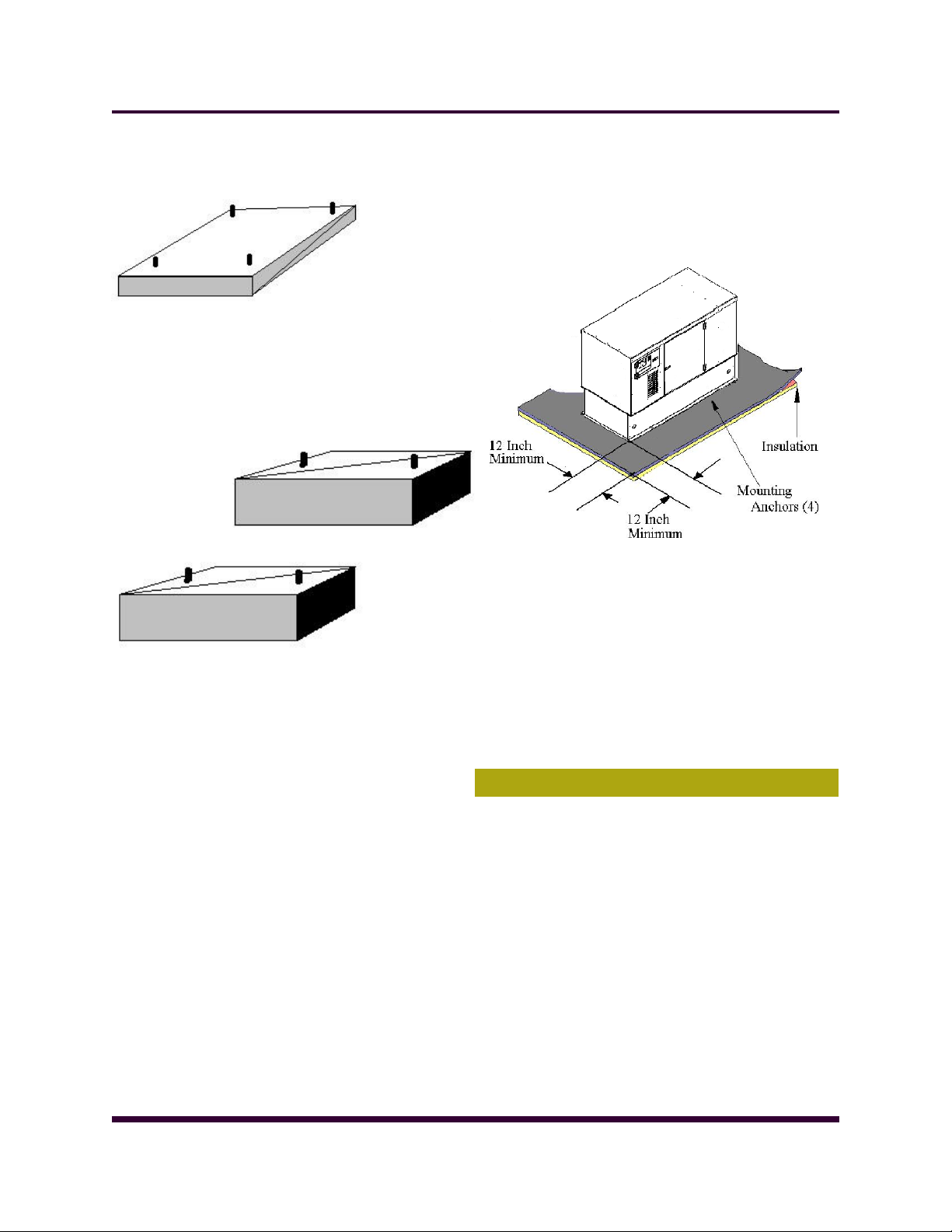
A Single (See Figure 1)or Double (See Figure 2) pedestal
base may be used. A height of at least 6 inches higher than
floor level is recommended.
AR-EXP-CUMMINS-07-00 OWNERS MANUAL
Page 13
Page 13
Figure 1- Single Pedestal Concrete Mount
Figure 2 - Double Pedestal Concrete Mount
A double pedestal base allows easier cleaning under
most generator's.
Double pedestals provide better access for inspecting
for oil or fuel tank leaks.
The generator should be retained to the pedestal base
with fasteners that are recommended by the generator
set manufacturer.
The concrete base should extend beyond the genera-
tor's "Footprint" by at least 12 Inches (305 mm) on all
sides.
The higher the mounting base is made, the easier the
unit will be to work on when performing maintenance,
service, or repairs. Typically bases are required to be
raised at least 6 inches (153 mm) above floor level.
Placing the unit higher than 6 inches sometimes has
the advantage of making it easier to change the unit's
oil.
Passing fuel lines and electrical conduit for a "stub-up"
through the concrete base is a standard practice of
gen-set installers.
Concrete foundations are typically mixed by volume.
The typical ratio of cement, sand, and aggregate is
1:2:3 with a maximum 4 inch (102 mm) slump and 28
day compressive strength of 2500 psi (173 kPa).
A generator can typically be mounted to a combustible
floor or roof, dependent upon code, however, the surface beneath the engine and beyond the engine to a
minimum distance of 12 inches (305 mm) must be
covered with a non combustible insulation and a minimum of 24 gage sheet metal between the insulation
and the generator. See Figure 3.
Figure 3. Combustible Floor and Roof
Optional vibration isolators beyond those already built
in the generator also help reduce transmitted noise,
however, it is recommended that one verify that the
generator manufacturer recommends the use of an
isolator.
Insulation must be a non-combustible material, typi-
cally a Fiberglas mat.
3. VENTILATION
3.1. OUTDOOR INSTALLATIONS - AIR COOLED UNITS
If your generator is expected to be in temperatures lower
than -20oF(-29oC) a cold weather package may be required.
The following general rules apply:
Where strong prevailing winds are anticipated, face the
engine end away from the wind.
Plan the installation carefully to prevent the cooling air
vents on the generator from becoming clogged by
leaves, grass, snow, etc.
AR-EXP-CUMMINS-07-00 OWNERS MANUAL
Page 14

Page 14
4. ELECTRICAL SYSTEM
There are a number of different generator systems and
typical loads in the context of electrical systems. Most systems, unless they contain automated switch gear, have a
means of disconnect between the generator and the
load. This is typically a transfer switch or disconnect. Ensure the contacts on the switch are rated for the
size of your system.
4.1. GENERAL ELECTRICAL SYSTEM
When mounting electrical panels, a 3 foot clearance is required and the use of an emergency light to illuminate the
unit during operation is typically required. Power for the
emergency light should be from both the primary utility and
the generator. This is highly recommend so that in the event
of a malfunction there is a light source to see to work on the
unit. Refer to your local building and electrical codes to
ensure compliance.
4.2. CONDUCTOR SIZING CONNECTION
This information is dependent upon your generator output
and intended load. When connecting cables to the generator, make connections at the generator first. Make the connections at the load last. Failure to do so may constitute a
fire or safety hazard.
All ampacities are typically calculated at 75 o C (Celsius)
(167 o F(Fahrenheit) in the conductor size charts. Building
wire conductors should be rated at 90oC(194oF) to allow for
different ambient temperatures that these conductors may
pass through.
All conductors are typically required by electrical code to be
copper. The recommended conductor sizes are based on
maximum current. Ampacities are found in NEC Article 310,
Table 310-16. Conductor resistances are found in NEC Table 8 "Conductor Properties".
4.3. CONNECTING THE GENERATOR
Please the refer to the electrical drawing of the unit and
your transfer switch documentation for information related.
Leave the installation only to a trained personnel and don‘t
forget to observe the local laws and permit requirements.
Errors during the installation may damage the equipment
and electrical devices connected to the unit and may create
fire and electrocution risks.
5. EXHAUST SYSTEM
5.1. GENERAL (EXHAUST SYSTEM)
Generator engines give off deadly carbon monoxide gas
through their exhaust systems.
Carbon monoxide gas, if breathed in sufficient concentrations, can cause unconsciousness or death. Exhaust gases
must be piped safely away from any room or enclosure that
houses a generator and to a well ventilated area where
AR-EXP-CUMMINS-07-00 OWNERS MANUAL
people will not be endangered.
Besides the possibility of carbon monoxide poisoning, exhaust piping becomes extremely hot during operation and
remains hot for a long time after shutdown. For that reason,
the following precautions are necessary:
Avoid contact with hot engines, exhaust manifolds,
exhaust piping and mufflers. Any of these can cause
severe burns.
Where piping must pass through combustible walls or
ceilings, special precautions must be taken to prevent
fire or heat damage such as using heat thimbles
through walls and ceilings.
5.2. GENERAL RULES FOR EXHAUST SYSTEM
When installing an exhaust system for a generator, the following rules should be considered:
Exhaust piping should be of wrought iron or steel hav-
ing adequate strength and durability.
Exhaust fittings may be of cast iron. A 9 inch spacing
(10 inches (250mm) recommended) from the exhaust
pipe and walls is also required by most local codes.
Low points in horizontal runs of piping should be pro-
vided with condensation traps, as well as condensation
drains.
Piping and mufflers must be properly supported and
connected.
A flexible length of exhaust pipe is required between
the engine exhaust manifold and rigid exhaust piping.
Exhaust piping must be terminated safely outside a
structure that houses a generator, in such a way that
hot gases and sparks will be discharged harmlessly
and will not blow against any combustible surface or
material.
Exhaust piping must not terminate under loading plat-
forms, structures, or near any opening in a building.
Where necessary, exhaust piping must be guarded
and/or insulated to prevent burns.
Provide a clearance of at least 9 inches (229mm)(10
inches (250mm) recommended) between exhaust
piping and any combustible material.
Keep exhaust piping well clear of fuel tanks, fuel lines,
etc.
5.3. RAIN CAP
A rain cap is recommended on the end of the exhaust pipe.
The rain cap is attached to the end of the pipe and opens
due to the pressure from the exhaust discharge force. The
rain cap protects the exhaust system from the environment
when the system is not running.
5.4. SPARK ARRESTOR
Use of a spark arrestor is required by the U.S. Department
of Forestry if located on lands under their jurisdiction. The
spark arrestor is recommended in areas where combustible
Page 15

6. INSTALLATION CHECKLIST
BATTERY INSTALLATION
❏ Battery is connected properly.
❏ Recommended battery is installed.
❏ Cables are clean and tight.
❏ Terminals are coated with anti-corrosion grease, and
terminal covers are positioned.
FUEL SYSTEM
❏ Complies with local and NFPA codes.
❏ Fuel is connected and checked for leaks.
❏ Correct fuel pressure (11-14 inches of water (0.6 psi) at
all load ranges).
❏ Load block adjusted for maximum power for natural gas
fuel.
LOCATION
❏ Unit is fastened to the appropriate mounting pad.
❏ Louvers are free from obstruction.
❏ Exhaust is clear of flammable objects and debris.
ELECTRICAL CONNECTIONS
❏ Complies with local code requirements and all National
Electrical Codes.
❏ Utility is connected and present.
❏ Transfer switch is connected.
❏ All wires running outside of the generator are in NEC-
approved conduit. *Note: Utility wires and transfer switch
control wires must be in separate conduit.
❏ Unit is grounded to an approved earth ground.
COOLING AND VENTILATING
❏ All inlets and outlets are free from obstruction.
OTHER
❏ Verify that the unit is filled to the proper level with the
proper break-in oil. Adjust as required.
Page 15
AR-EXP-CUMMINS-07-00 OWNERS MANUAL
Page 16

Page 16
GENERATING SET
OPERATION AND
MAINTENANCE
AR-EXP-CUMMINS-07-00 OWNERS MANUAL
Page 17

Page 17
7. PRE-OPERATION CHECK
BREAK-IN
During the engine break-in period, observe the following by
all means:
Change engine oil and oil filter cartridge after the first
50 hours of operation
2. DAILY CHECK
To prevent trouble from occurring, it is important to know
the conditions of the engine well. Check it before starting.
CAUTION
To avoid personal injury:
• Be sure to install shields and safeguards attached to the
engine when operating.
• Stop the engine at a flat and wide space when checking.
• Keep dust or fuel away from the battery, wiring, muffler
and engine to prevent a fire.
Check and clear them before operating everyday. Pay attention to the heat of the exhaust pipe or exhaust gas so that it
can not ignite trash.
1) Oil or water leaks
2) Engine oil level and contamination
3) Amount of fuel
4) Amount of coolant
5) Dust in air cleaner dust cup
6) Damaged parts and loosened bolts and nuts
7) Emergency stop off.
8) Battery connections
9) Wiring in good condition
3. CONTROL PANEL
The DSE 5120 automatic mains failure module has been
primarily designed to start and stop the generator depending upon the mains supply status.
External autostart from a switch and user operated manual
start is also provided. Additionally, you have the facility to
view all the system operating parameters via the LCD display.
The DSE 5120 module monitors the engine, indicating the
operational status and fault conditions automatically
shutting down the engine and giving a true first up fault
condition of an engine failure by a flashing COMMON
ALARM LED. Exact failure mode information is indicated by
the LCD display on the front panel.
AR-EXP-CUMMINS-07-00 OWNERS MANUAL
7.1. Automatic Mode of Operation
This mode is activated by pressing the pushbutton. An LED
indicator beside the button confirms this
action.
When the mains supply fails (or Remote Start signal (if configured) is applied) the following sequence is initiated:
The mains available LED extinguishes (if the sequence was
started by mains failure) and the relevant mains over/under
voltage LED will illuminate.
The Remote Start Active indicator illuminates if the sequence is started by the remote start input. To allow for
short term mains supply brownouts or false start signals the
Start Delay timer is initiated. After this delay, if the pre-heat
output option is selected then the pre-heat timer is initiated,
and the corresponding auxiliary output will energize.
After the above delays the Fuel Solenoid is energized, then
one second later, the Starter Motor is engaged. The engine
is cranked for a pre-set time period. If the engine fails to fire
during this cranking attempt then the starter motor is disengaged for the pre-set rest period. Should this sequence
continue beyond the set number of attempts (fixed at 3),
the start sequence will be terminated and Fail to Start fault
will be displayed accompanied by a flashing shutdown symbol.
Fail to start Shut Down
When the engine fires, the starter motor is disengaged and
locked out at a pre-set frequency from the Alternator output.
After the starter motor has disengaged, the Safety On timer
is activated, allowing Oil Pressure, High Engine Temperature, Under-speed, Charge Fail and any delayed Auxiliary
fault inputs to stabilize without triggering the fault.
Once the engine is running, the Warm Up timer, if selected
is initiated, allowing the engine to stabilize before accepting
the load.
If the mains supply returns (or the remote start signal is
removed if the start sequence was initiated by remote
start), before the warm up timer has expired, the mains
supply is kept on load and the return timer will begin.
At the end of the warming timer, If the mains supply is still
failed, or the remote start signal is still active, the load is
transferred to the generator - First the mains load switching
device is opened, then ¾ second later, the close generator
output is activated.
On return of the mains supply the mains in limit LED will
illuminate, and the under/overvolts LEDs will extinguish.
Additionally (or upon removal of the Remote Start signal if
Page 18

Page 18
the start was initiated by remote start), the return delay
timer is initiated after which the load Transfer signal is deenergized, removing the load. ¾ second later, the mains
load switch is closed, returning the mains on load. If the
generator set has been on load, The Cooling timer is then
initiated, allowing the engine a cooling down period off load
before shutting down.
Once the Cooling timer expires the Fuel Solenoid is deenergized, bringing the generator to a stop. Should the
mains supply fail, or Remote Start signal be re-activated
during the cooling down period, the set will return on load.
7.2. Manual Operation
To initiate a start se- quence in MANUAL, press
the pushbutton. When the controller is in the
manual mode (indicated by an LED indicator beside the
button), pressing the START (I) button will initiate the start
sequence.
If the pre-heat output option is selected this timer is then
initiated, and the auxiliary output selected is energized.
After the above delay the Fuel Solenoid is energized, then
the Starter Motor is engaged. The engine is cranked for a
pre-set time period. If the engine fails to fire during this
cranking attempt then the starter motor is disengaged for
the pre-set rest period. Should this sequence continue beyond the set number of
attempts (fixed at 3), the start sequence will be terminated
and Fail to Start fault will be displayed accompanied by a
flashing shutdown indicator.
Fail to start
Shut Down
When the engine fires, the starter motor is disengaged and
locked out at a pre-set frequency from the Alternator output. Alternatively a Magnetic Pickup mounted on the flywheel housing can be used for speed detection (This is
selected using the front panel editor or PC). After the starter
motor has disengaged, the Safety On timer is activated,
allowing Oil Pressure, High Engine Temperature, Underspeed, Charge Fail and any delayed Auxiliary fault inputs to
stabilize without triggering the
fault. Once the engine is running, the Warm Up timer, if
selected is initiated, allowing the engine to stabilize before
it can
be loaded.
The generator will run off load, unless the mains supply
fails, or a Remote Start signal is applied. The generator will
continue to run On load regardless of the state of the mains
supply and/or remote start input until the Auto mode is
selected, the Stop button is pressed, or an electrical trip or
shutdown alarm is detected. Selecting STOP (O) deenergizes the FUEL SOLENOID, bringing the generator to a
stop.
7.3. Protections
The module will indicate that an alarm has occurred in several ways:
The ―Common alarm‖ LED will illuminate (Warning =
Red steady, Shutdown = Red Flashing)
If appropriate, the LCD display or LED indicators will
display the appropriate alarm icon i.e. for battery
charging failure.
If no alarms are present the
LCD
will extinguish any alarm icons.
In the event of a warning alarm the LCD will display the
appropriate icon. If a shutdown then occurs the module will
display the appropriate icon. The original warning alarm
icon will remain displayed.
Charge alternator warning (all
symbols steady)
Charge alternator warning
indicator still present, common alarm indicator has
changed to a shutdown symbol and is now flashing. Also
present is the flashing overspeed LED.
Overspeed and Shutdown alarm Icons are displayed flashing. The original warning will remain displayed as long as
the triggering conditions remain. Any subsequent warnings
or shutdowns that occur will be displayed steady, therefore
only the first-up shutdown will appear flashing.
Warnings
Warnings are non-critical alarm conditions and do not affect
the operation of the generator system, they serve to draw
the operators attention to an undesirable condition. In the
event of a warning alarm the LCD will display:
AR-EXP-CUMMINS-07-00 OWNERS MANUAL
Page 19

Page 19
BATTERY CHARGE FAILURE
If the module does not detect a voltage from the warning
light terminal on the auxiliary charge alternator the icon will
illuminate.
FAIL TO STOP
If the module detects the engine is still running when the
Fail to stop timer‘ expires, then the module will display:
AUXILIARY INPUTS
If an auxiliary input has been configured as a warning the
appropriate LCD segment will be displayed.
SHUTDOWNS
Shutdowns are latching and stop the Generator. The alarm
must be cleared, and the fault removed to reset the module. In the event of a shutdown alarm the LCD will display:
FAIL TO START, if the engine does not fire after the pre-set
number of attempts has been made a shutdown will be
initiated. The icon will illuminate.
EMERGENCY STOP
Removal of the Positive DC Supply from the Emergency
Stop input initiates the following sequence, firstly it will initiate a controlled shutdown of the Generator and prevent any
attempt to restart the Generator until the Emergency Stop
cur. The icon will illuminate.
OVERSPEED / OVERFREQUENCY
If the engine speed exceeds the pre-set trip a shutdown is
initiated. The icon will illuminate. Overspeed is not delayed,
it is an immediate shutdown.
UNDERSPEED / UNDERFREQUENCY
If the engine speed falls below the pre-set trip after the
Safety On timer has expired, a shutdown is initiated. The
icon will illuminate.
OIL PRESSURE SENDER OPEN CIRCUIT
If the module detects a loss of signal from the oil pressure
sender (open circuit) a shutdown is initiated. The LCD will
indicate:(Steady) (And ‗-----‗ on the engine oil pressure in-
strument). Sender failure is not delayed, it is an immediate
shutdown.
AUXILIARY INPUTS, if an auxiliary input has been configured
as a shutdown the appropriate LCD segment will be displayed:
LOSS OF SPEED SIGNAL
If the speed sensing signal is lost during cranking, a shutdown is initiated. The icon will illuminate (Steady). As engine
speed cannot be determined, the entire ―fail to stop‖ timer
is observed before the alarm can be reset and the engine
restarted.
7.4. DESCRIPTION OF CONTROLS.
The following section details the function and meaning of
the various controls on the module.
push-button has been reset. Secondly it removes the Positive DC supply from both the Fuel Solenoid and Starter Solenoid. The icon will illuminate.
LOW OIL PRESSURE
If the module detects that the engine oil pressure has fallen
below the low oil pressure trip setting level after the Safety
On timer has expired, a shutdown will occur. The icon will
illuminate.
HIGH ENGINE TEMPERATURE
If the module detects that the engine coolant temperature
has exceeded the high engine temperature trip setting level
after the Safety On timer has expired, a shutdown will oc-
AR-EXP-CUMMINS-07-00 OWNERS MANUAL
Page 20

Page 20
Typical LCD screens
Instruments
The LCD displays the various engine parameters such as
‗ENGINE SPEED‘, ‗OIL PRESSURE‘, ‗HOURS RUN‘, etc. Each
instrument is displayed with
the appropriate units of measure. In this example, the values
being displayed are Generator
phase to phase AC voltages
Alarm Icons
The LCD also d i s - plays the exact nature
of any alarm condition that may have occurred such as LOW
OIL PRESSURE using appropriate icons. This allows very
specific alarm conditions to
be brought to the operators‘
attention. Refer to the
‗Protections‘ section of this
manual for details of the
alarms.
User Defined Indications
The LCD displays the user-defined indications when configured and active. The icons will illuminate and point to the
appropriate text insert label. These indications can be used
to indicate internal states (i.e. Engine Running, Safety On,
etc).
User Defined Alarms
The LCD displays the user-defined alarms when configured
and active. The icons will illuminate and point to the appropriate text insert label. These alarms can be used to indi-
cate the operation of external alarms (i.e. ‗Low Fuel Level‘,
‗Low Coolant level‘ etc) or to indicate internal alarms (i.e.
Fail to Stop, MPU fault, etc).
LCD Display Areas
NOTE:- The Engine Hours Run counter will only
display the accumulated hours to the nearest 12
Minutes (0.2Hr). The accumulated time will be
recorded in HH:MM however.
CAUTION:
If the DC supply to the module is interrupted the hours run
counter will not remember any ‗undisplayed‘ minutes accu-
mulated since the last 12 Minute display update.
i.e.
10 Hours 38 Minutes accumulated before DC supply is
removed… (10.6 Hours displayed) would become …10
Hours 36Minutes on restoration of DC supply. (10.6 Hours
still displayed) This will only occur in the event of a total DC
supply break and will NOT occur if the module is simply
switched to the Stop/Reset position.
VIEWING THE INSTRUMENTS
AR-EXP-CUMMINS-07-00 OWNERS MANUAL
Page 21

Page 21
It is possible to manually scroll to display the different instruments by repeatedly operating the scroll button. Once
selected the instrument will remain on the LCD display until
the user selects a different instrument or after a period of
inactivity the module will revert to the initial display (Hz/
RPM).
Instrument Page Order:-
• Frequency / RPM
• AC Voltage Line-Neutral (<<<Not Shown on 3 phase 3
wire (Delta) version of the module)
• AC Voltage Line-Line
• AC Line Current
• Oil Pressure
• Coolant temperature
• Engine Hours Run
USER CONFIGURABLE LCD INDICATORS
These LCD‘s can be configured by the user to indicate any
on of the different functions based around the following:
WARNINGS and SHUTDOWNS
Specific indication of a particular warning or shutdown condition, backed up by LCD indication (!)- Such as Low Oil
Pressure
Shutdown, Low Coolant level, etc.
STATUS INDICATIONS
Indication of specific functions or sequences derived from
DC Battery Voltage
Pressing the button again will scroll through each
individual instrument eventually returning to the
original instrument displayed.
NOTE:-Once selected the instrument will remain on the LCD
display until the user selects a different instrument or after
a period of inactivity the module will revert to the initial
display.
Indicators
COMMON ALARM LCD indicators
These indicate when an alarm condition is present. The
Alarm icons or LEDs will detail the exact nature of the
alarm. (warning) or (shutdown)
the modules operating state - Such as Safety On, Pre-
heating, Generator Available, etc.
Controls
This button places the module into its Stop/reset mode.
This will clear any alarm conditions for which the triggering
criteria have been removed. If the engine is running and
this position is selected, the module will automatically instruct the changeover device to unload the generator (‘Load
transfer’ becomes inactive (if used)). The fuel supply will be
removed and engine will be brought to a standstill. Should a
remote start signal be present while operating in this mode,
a remote start will not occur.
Manual
This mode is used to allow manual control of the generator
functions. Once in Manual mode the module will respond to
the start (I) button and start the engine and run off load. If
the engine is running off-load in the Manual mode and either remote start signal becomes present or the mains supply fails, the module will automatically instruct the changeover device to place the generator on load (‘Load transfer’
becomes active (if used)). Should the remote start signal
AR-EXP-CUMMINS-07-00 OWNERS MANUAL
Page 22

Page 22
then be removed the
generator will remain on load until either the ‗STOP/RESET‘
or ‗AUTO‘ positions is selected.
Auto
This button places the module into its
‗Automatic‘ mode. This mode allows the
module to control the function of the generator automatically. The module will monitor the remote start input and
the mains supply and once a start condition is signaled the
set will be automatically started and placed on load (‘Load
transfer’ becomes active (if used)). If the starting signal is
removed or the mains supply returns, the module will automatically transfer the load from the generator and shut the
set down observing the stop delay timer and cooling timer
as necessary. The module will then await the next start
event. For further details please see the more detailed de-
scription of ‘Auto Operation’ earlier in this manual.
Test
This mode is used to allow on load test of the
genera tor func- tions. Once in Test mode
the module will respond to the start (I)
button and start the engine and run on load until either the
‗STOP/RESET‘ or ‗AUTO‘ positions is selected.
Start
This button is only active in MANUAL or TEST
modes. Pressing this button in manual mode will start the
engine and run off load. If the generator is running offload
in the Manual mode and a remote start signal becomes
present or the mains supply returns, the module will automatically instruct the changeover device to place the generator on load (‘Load transfer’ becomes active (if used)).
Should the remote start signal then be removed the generator will remain on load until either the ‗STOP/RESET‘ or
‗AUTO‘ positions is selected.
Power Up LCD display
When DC power is first applied to the 5120 controller, a
short LCD test is performed that illuminates all
LCD segments. After this,
the module‘s software
revision number is shown
briefly.
For example, this display
is showing software revision 1.00
ENTERING CONFIGURATION MODE
NOTE:- Configuration mode can ONLY be entered when the
module is in the STOP mode and the engine is at rest.
Press the DOWN and STOP buttons to enter configuration mode.
The first configurable parameter is displayed. In this example, the Start delay timer (parameter 0) is currently set
to 5s.
Editing Analog Values
Enter the front panel configuration editor as described previously. Press the button to enter adjust mode. When in
adjust mode (indicated by the flashing icons in the module
display), pressing the + or – buttons will change the selected parameter to the desired value. Press the button
to ‗save‘ the value. The icons will stop flashing to confirm
that it has been saved.
To select the next parameter to edit, press the + button.
Continuing to press the + / – buttons will cycle through the
adjustable parameters in the order shown in the following
lists. Timers display in seconds up to 59 seconds, then in
minutes up to the timer‘s maximum value. For instance, the
parameter being
displayed in this
example is the
co o li n g ti m er
(parameter 7). It‘s
current value is
2.5mins (2mins
30secs).
7.5 EDITING A ‗LIST‘ VALUE
Some configuration
parameters have a
list of options to select from. These include input and output settings.
This example shows
the setting for LCD
i n d i c a t o r 3
(parameter 29). It‘s current setting is 3 (‗Close Generator‘
from the lists shown below.)
NOTE:- When in adjust mode (indicated by the flashing
icons in the module display), pressing the (stop mode) but-
AR-EXP-CUMMINS-07-00 OWNERS MANUAL
Page 23

ton will cancel any changes made to the current parameter,
reverting to the last ‗saved‘ value. This also exits adjust
mode.
NOTE:- To exit the front panel configuration editor at any
time press the STOP button. Ensure you save any changes
you have made by pressing the button first if necessary.
Timers and Analogue Settings
Page 23
NOTE:- Setting a timer to zero (0) will disable it. Timer settings increment from 0 to 60s in steps of 1s and from 1
minute to the maximum value in steps of 30 seconds (0.5
minutes) (where applicable)
NOTE:- Setting Flywheel teeth to zero (0) will disable magnetic pickup speed sensing. In this instance, engine speed
is derived from the alternator output frequency.
NOTE:- CT values increment from 10-100 in steps of 10A,
and from 100 to 6000A in steps of 50A. CT secondary must
be 5A.
AR-EXP-CUMMINS-07-00 OWNERS MANUAL
Page 24

Page 24
7.6 Panel Trouble Shooting
NOTE:- The above fault finding is provided as a guide check-list only. As it is possible for the module to be configured to provide a wide
range of different features always refer to the source of your module configuration if in doubt.
AR-EXP-CUMMINS-07-00 OWNERS MANUAL
Page 25

8. BREAKER-INSTALLATION INFORMATION
Page 25
AR-EXP-CUMMINS-07-00 OWNERS MANUAL
Page 26

Page 26 Page 26
AR-EXP-CUMMINS-07-00 OWNERS MANUAL
Page 27

FG MOLDED CASE
15-150 AMPS
Page 27 Page 27
AR-EXP-CUMMINS-07-00 OWNERS MANUAL
Page 28

JG MOLDED CASE
175-250 AMPS
Page 28
AR-EXP-CUMMINS-07-00 OWNERS MANUAL
Page 29

Page 29
AR-EXP-CUMMINS-07-00 OWNERS MANUAL
Page 30

KG MOLDED CASE
300-400 AMPS
Page 30
AR-EXP-CUMMINS-07-00 OWNERS MANUAL
Page 31

Page 31
AR-EXP-CUMMINS-07-00 OWNERS MANUAL
Page 32

LG MOLDED CASE
450-600 AMPS
Page 32
AR-EXP-CUMMINS-07-00 OWNERS MANUAL
Page 33

Page 33
AR-EXP-CUMMINS-07-00 OWNERS MANUAL
Page 34

MG MOLDED CASE
700-800 AMPS
Page 34
AR-EXP-CUMMINS-07-00 OWNERS MANUAL
Page 35

Page 35
AR-EXP-CUMMINS-07-00 OWNERS MANUAL
Page 36

NG MOLDED CASE
Page 36
900-1200 AMPS
AR-EXP-CUMMINS-07-00 OWNERS MANUAL
Page 37

1600-2500 AMPS
Page 37
AR-EXP-CUMMINS-07-00 OWNERS MANUAL
Page 38

Page 38
9. ENGINE
9.1. CHECKS DURING OPERATION
While running, make the following checks to see that all
parts are working correctly.
Radiator Cooling water (Coolant)
To avoid personal injury:
Do not remove radiator cap until coolant temperature
is well below its boiling point. Then loosen cap slightly
to the stop position, to relieve any pressure, before
removing cap completely.
When the engine overheats and hot coolant overflows
through the overflow pipe and cannot be stopped, stop the
engine immediately and make the following checks to determine the cause of trouble:
1. Check to see if there is any coolant leak;
2. Check to see if there is any obstacle around the cooling
air inlet or outlet;
3. Check to see if there is any dirt or dust between radiator
fins and tube;
4. Check to see if the fan belt is too loose;
5. Check to see if radiator water pipe is clogged; and
6. Check to see if anti-freeze is mixed into coolant in warm
seasons.
Fuel
To avoid personal injury:
• Fluid escaping from pinholes may be invisible. Do not use
hands to search for suspected leaks; Use a piece of cardboard or wood, instead, If injured by escaping fluid, see a
medical doctor at once. This fluid can produce gangrene or
a severe allergic reaction.
• Check any leaks from fuel pipes or fuel injection pipes.
Use eye protection when checking for leaks. Be careful not
to empty the fuel tank. Otherwise air may enter the fuel
system, requiring fuel system bleeding.
While the engine is run within the rated output range:
• The color of exhaust remains colorless.
• If the output slightly exceeds the rated level, exhaust may
become a little colored with the output level kept constant.
• If the engine is run continuously with dark exhaust emis-
sion, it may lead to trouble with the engine.
• Immediately stop the engine if;
• The engine suddenly slow down or accelerates.
• Unusual noises suddenly appear.
• Exhaust fumes suddenly become very dark.
9.2. MAINTENANCE SCHEDULE
Perform maintenance at whichever interval that occurs first.
At each scheduled maintenance interval, perform all previous maintenance checks that are due for scheduled maintenance.
Daily or Refueling - Maintenance Check
(4)
Air Intake Piping - Inspect
Air Tank and Reservoirs - Drain
Cooling Fan - Check/Correct
Crankcase Breather Tube - Inspect
Drive Belts - Check/Correct
Engine Coolant Level - Check/Correct
Engine Lubricating Oil Level - Check/Correct
Fuel-Water Separator - Drain
Every 250 Hours or 3 Months - Maintenance
(1, 4)
Check
Air Cleaner Restriction - Check/Correct
Air Compressor Mounting Hardware - Check/Correct
Charge Air Cooler - Check/Correct
Charge Air Piping - Check/Correct
Fuel Injection Pump Mounting Hardware - Check/
Correct
Lubricating Oil and Filters - Change
Radiator Hoses - Check
Every 500 Hours or 6 Months - Maintenance
(2, 3, 4)
Check
Engine Coolant - Antifreeze Check
Fuel Filter, Canister-Type - Replace
Fuel Filter, Spin-on-Type - Replace
Lubricating Oil and Filters - Change
Every 1000 Hours or 1 Year - Maintenance Check
(4)
Cooling Fan Belt Tensioner - Check/Correct
Fan Hub, Belt-Driven - Check/Correct
Overhead Set - Adjust
Every 2000 Hours or 2 Years - Maintenance Check
(3, 4)
Air Compressor Discharge Line - Check/Correct
Cooling System - Drain, Flush, and Fill
Vibration Damper, Rubber - Check
Vibration Damper, Viscous - Check
1. NOTE: The lubricating oil and lubricating oil filter
interval can be adjusted based on application, fuel
consumption, gross vehicle weight, and idle time.
For engines whose aspiration is jacket watercooled, turbocharged only, or natural, refer to
Table in the Oil Drain Intervals section.
2. The lubricating oil and lubricating oil filter interval
can be adjusted based on application, fuel consumption, gross vehicle weight, and idle time. For
AR-EXP-CUMMINS-07-00 OWNERS MANUAL
Page 39

Table 1: Jacket Water Cooled, Turbocharged Only, or Naturally Aspirated Engines
Page 39
Cummins Engine Standard
Classification
American Petroleum Institute
Classification
International Classifications All Engine Ratings
(CES) (API)
CES-20078, CES-20077, CES-
20076, CES-20072, CES20071
CES-20075 API CF-4/SG
API CI-4/SK, API CI-4, API
CH-4, API CH-4/SJ
API CG-4/SH, API CD, API
CE
ACEA E-5, Global DHD-1 250 Hours or 3 Months
ACEA E-3, ACEA E-2, JAMA
DH-1
ACEA E-1
Table 2: Charge Air Cooled Engines
Cummins Engine Standard
Classification
American Petroleum Institute
Classification
International Classifications All Engine Ratings
(CES) (API)
CES-20078, CES-20077, CES-
20076, CES-20072, CES20071
CES-20075 API CF-4/SG
API CI-4/SK, API CI-4, API
CH-4, API CH-4/SJ
API CG-4/SH, API CD, API
CE
ACEA E-5, Global DHD-1 500 Hours or 6 Months
ACEA E-3, ACEA E-2, JAMA
DH-1
ACEA E-1
150 Hours or 6 Weeks
Obsolete. Donot use.
250 Hours or 3 Weeks
Obsolete. Donot use.
9.3. CUMMINS/FLEETGUARD® FILTER SPECIFICATIONS
Fleetguard® is a subsidiary of Cummins Inc. Fleetguard® filters are developed through joint testing at Cummins and
Fleetguard®. Fleetguard® filters are standard on new Cummins engines. Cummins Inc. recommends their use.
Fleetguard® products meet all Cummins Source Approval Test standards to provide the quality filtration necessary to
achieve the engine's design life. If other brands are substituted, the purchaser should insist on products that the supplier
has tested to meet Cummins high-quality standards.
Cummins can not be responsible for problems caused by non-genuine filters that do not meet Cummins performance or
durability requirements.
Filter Part
Numbers
Cummins Part
Number
Fleetguard®
Part Number
Lubricating Oil
Filter B3.9
Lubricating Oil
Filter B4.5
Lubricating Oil
Filter B5.9
Fuel Filter B3.9 Fuel Filter B4.5 Fuel Filter B5.9
3934429 3934429 3934430 3966139 3991350 3900632
LF9100 LF9100 LF9098 FF9413 FS19608
FF9417
AR-EXP-CUMMINS-07-00 OWNERS MANUAL
Page 40

Page 40
WARNING
Do not mix gasoline, alcohol, or gasohol with diesel fuel. This mixture can cause an explosion.
CAUTION
Due to the precise tolerances of diesel injection systems, it is extremely important that the fuel be kept clean and free of
dirt or water. Dirt or water in the system can cause severe damage to both the fuel pump and the fuel injectors.
Cummins Inc. recommends the use of ASTM number 2D fuel. The use of number 2 diesel fuel will result in optimum engine performance.
At operating temperatures below 0°C [32°F], acceptable performance can be obtained by using blends of number 2D
and number 1D.
NOTE: Lighter fuels can reduce fuel economy.
NOTE: Engines equipped with diesel particulate filters require the use of diesel fuel with 30 ppm sulfur maximum. There
are no acceptable substitutes.
The viscosity of the fuel must be kept above 1.3 cSt at 40°C [104°F] to provide adequate pumping and lubricating characteristics to fuel system components.
The following chart lists acceptable substitute fuels for this engine.
Acceptable Substitute Fuels
Number
1D
Diesel
(3)
A OK Not OK A A A A Not OK Not OK Not OK
An "A" means OK only if fuel lubricity is adequate. This means the BOCLE number is 3100 or greater as measured by
ASTM specification D6078, Scuffing Load Ball On Cylinder Evaluator (SLBOCLE). Lubricity can also be measured by ASTM,
specification D6079, ISO 12156, High Frequency Reciporating Rig (HFRR) in which the fuel must have a wear scar diameter of 0.45 mm [0.02 in] or less.
Any adjustment to compensate for reduced performance with a fuel system using alternate fuel is not warrantable.
Winter blend fuels, such as found at commercial fuel-dispensing outlets, are combinations of number 1D and 2D diesel
fuels and are acceptable.
(1) (2)
Number
Diesel
2D
(3)
Number
1K Kero-
sene
Jet-A Jet-A1 JP-5 JP-8 Jet-B JP-4 CITE
CAUTION
A sulfated ash limit of 1.85 percent has been placed on all engine lubricating oils recommended for use in Cummins
engines. Higher ash oils can cause valve and/or piston damage and lead to excessive oil consumption.
CAUTION
The use of a synthetic-base oil does not justify extended oil change intervals. Extended oil change intervals can
decrease engine life due to factors such as corrosion, deposits, and wear.
AR-EXP-CUMMINS-07-00 OWNERS MANUAL
Page 41

Page 41
The use of quality engine lubricating oils, combined with appropriate oil drain and filter change intervals, is a critical factor
in maintaining engine performance and durability.
Cummins Inc. recommends the use of high-quality SAE 15W-40 heavy-duty engine oil, such as Valvoline® Premium
Blue®, which meets performance specifications as listed below.
Cummins Engineering Standard Classification (CES)
API CD API CE API CG-4/SH ACEA E-1
CES-20075 API CF-4/SG
CES-20071 CES-20076 API CH-4/SJ API CH-4 Global DHD-1
American Petroleum Institute
Classification (API)
International Classifications Comments
OBSOLETE. DO NOT
USE.
ACEA E-2 ACEA E-3 JAMA
DH-1
Minimum acceptable oil classification for midrange engines.
Acceptable oil classification
for midrange engines.
Similar in performance to
CES-20071 but validated un-
CES-20072 CES-20077 API CH-4 ACEA E-5 Global DHD-1
der European test standards.
Excellent oil for midrange
engines.
CES-20078 API CI-4/SK API CI-4
Excellent oil for midrange
engines.
NOTE: In areas where CH-4/SJ or CG-4/SH oils are not available, refer to Oil Drain Intervals in Section 2.
A sulfated ash limit of 1.0 mass percent is suggested for optimum valve and piston deposit and oil consumption control.
As the engine oil becomes contaminated, essential oil additives are depleted. Lubricating oils protect the engine as long
as these additives are functioning properly. Progressive contamination of the oil between oil and filter change intervals is
normal. The amount of contamination will vary depending on the operation of the engine, kilometers or miles on the oil,
fuel consumed, and new oil added.
Extending oil and filter change intervals beyond the recommendations will decrease engine life due to factors such as
corrosion, deposits, and wear.
Special ―break-in‖ engine lubricating oils are not recommended for new or rebuilt Cummins engines. Use the same type of
oil during the break-in as is used in normal operation.
The use of low-viscosity oils, such as 10W or 10W-30, can be used to aid in starting the engine and in providing sufficient
oil flow at ambient temperatures below -5°C [23°F]. However, continuous use of low-viscosity oils can decrease engine
life due to wear. Refer to the accompanying chart.
If an engine is operated in ambient temperatures consistently below -23°C [-9°F] and there are no provisions to keep the
engine warm when it is not in operation, use a synthetic CH/SI or CH/SK or higher API classification engine oil with adequate low-temperature properties such as 5W-20 or 5W-30.
The oil supplier is responsible for meeting the performance service specifications represented with its product.
Use low-silicate antifreeze that meets ASTM4985 (GM6038M specification) criteria. Fully formulated coolant must meet
ASTM D-6210/D-6211. Cummins Inc. recommends using either a 50/50 mixture of good-quality water and fully formulated antifreeze, or fully formulated coolant when filling the cooling system.
Good-quality water is important for cooling system performance. Excessive levels of calcium and magnesium contribute to
scaling problems, and excessive levels of chlorides and sulfates cause cooling system corrosion.
AR-EXP-CUMMINS-07-00 OWNERS MANUAL
Page 42

Water Quality
Page 42
Calcium Magnesium
(hardness)
Chloride 40 ppm as (CI)
Sulfur
Cummins Inc. recommends using Fleetguard® Compleat. It is available in both glycol forms (ethylene and propylene).
Fully formulated antifreeze must be mixed with good-quality water at a 50/50 ratio (40- to 60-percent working range). A
50/50 mixture of antifreeze and water gives a -36°C [-33°F] freezing point and a 108°C [226°F] boiling point, which is
adequate for locations in North America. The actual lowest freezing point of ethylene glycol antifreeze is at 68 percent.
Using higher concentrations of antifreeze will raise the freezing point of the solution and increase the possibility of a silica
gel problem.
Do not use sealing additives in the cooling system. The use of sealing additives will:
Maximum 170 ppm as
(CaCO3 + MgCO3)
100 ppm as (SO4)
Buildup in coolant low-flow areas
Plug the radiator and oil cooler Possibly damage the water pump seal.
Do not use soluble oils in the cooling system. The use of soluble oils will:
Corrode brass and copper
Damage heat transfer surfaces
Damage seals and hoses.
10. ALTERNATOR
For safety purposes it is necessary that any testing or maintenance carried out on electrical machine are performed by
qualified and authorized personnel, and all operation must be performed when the machine is stopped, at ambient temperature and disconnected from any supply source (including the auxiliary circuits such as the anti-condensation heaters).
Furthermore all measures must be taken to avoid restarting the gen-set during maintenance.
10.1. INSPECTION AND MAINTENACE INTERVALS
Inspection and maintenance should take into account the importance of the plant ambient conditions (dust etc.) and operating conditions.
As a general rule, the machine should be subjected to a first inspection after approx. 500 operating hours (in any case not
more than 1 year) and subsequent inspections when performing maintenance on prime mover.
When performing inspection check that:
The generator operates smoothly, without noise or irregular vibrations due to bearing deterioration
The operating data complies with that detailed on the rating plate
The air inlet openings are not obstructed
The supply cables show no signs of deterioration and connections are firmly tight
The electrical connections are in perfect condition (undamaged)
Screws and nuts are firmly tightened.
10.2. MAINTENNCE OF BEARINGS
The lifetime of bearings is determined by multiple factors and specifically by:
The lifetime of the grease. ·
The environmental conditions and working temperature.
The external loads and vibrations.
The bearings (D.E. and N.D.E. side are prelubricated sealed type (life lubrication), with sufficient grease quantity for a lo ng
operating
time.
The life expected time is, in case of normal operating condition, of about 20000 hours for all bearings.
AR-EXP-CUMMINS-07-00 OWNERS MANUAL
Page 43

Page 43
In case of complete overhaul of genset, the bearing of the
generator should be changed.
On request prelubricated bearings with regreasing system
can be mounted. When regreasing use 20/ 30 grams of
grease.
Following types of grease are to be recommended for normal application:
MOBIL OIL: MOBILUX 3
SHELL: ALVANIA 3
AGIP: GR MW 3
ESSO: BEACON 3
10.3. VOLTAG REGULATOR
a finer regulation, or to adjust the voltage from control
panel or to limit the voltage range, it is possible to insert an
external potentiometer.
P2/FREQ- Potentiometer for changing the low speed protection. Usually it is set in order to reduce the excitation when
the speed is 10 % below the rated value at 50 Hz. By removing the bridge which is normally shorting the auxiliary
terminals 60-Hz of the regulator, the low speed protection
acts properly for 60 Hz.
P3/STAB- Potentiometer for stability adjust. By rotating it
clockwise the stability of the regulator increases, but the
response time becomes longer.
P4/AMP- Potentiometer for chancing the overexcitation limit
device. The overexcitation limit device helps to protect the
excitation system. This device is delayed to avoid transitory
conditions (in case of overexcitation).
On the AVR there is a protecting fuse. ln case it should be
necessary to replace it, high speed fuses should be used; in
addition they should have high breaking resistance with a
rated voltage of 50OV, and rated current of 1OA. The AVR is
connected to the terminals of the generator and to exciter
using FAST—ON terminals.
The generators are provided with automatic voltage regulator. The AVR is provided with potentiometers to adapt the
characteristics of the AVR to different operating conditions.
The AVR is provided with adjustable stability circuitry to
allow operations in a wide range of applications.
The AVR is equipped also with protecting circuit allowing
ARMTRONG POWER
SYSTEMS
the generator to operate underspeed if not loaded.
ATTENTIONI: it is not advisable to have the generator operating loaded when the frequency (speed) is below the rated
value: this kind of operation is an overload for the whole
generator excitation system.
CONNECTION OF AVR
The AVR is connected to the terminals of the generator and
Phone: (305) 470 0058
Fax: (305) 470 0068
Toll Free: 1-800 238 0732
8254 NW 58th St., Miami, FL.
33166, U.S.A.
e-mail:
sales@armstrongpower.com
to exciter FAST-ON terminals.
USE OF POTENTIOMETERS
P1/VOLT- Potentiometer for adjusting the output voltage of
the generator; it allows a wide range of voltage setting (i.e.
between 350 and 470 V; or between 170 and 260 V depending on winding connections)). When resetting the potentiometer, the voltage has to be set in the range +5%,-5%
around the rated voltage of the machine. In order to obtain
AR-EXP-CUMMINS-07-00 OWNERS MANUAL
 Loading...