


GP4020 GPS Baseband Processor Design Manual
Publication Number: DM5280
Issue: 3
Revision: 002
Issued: January 2002
Zarlink Semiconductor, Cheney Manor
Swindon, Wiltshire, United Kingdom, SN2 2QW

Manual Revision History
Version Revision Date Update Summary
1 001 February 2000 First Version
2 001 August 2000 GND and VDD pins marked as type “PW R” in t ables 2.2 and 20.1.
Modified TESTMODE (pin 74) definition.
Removal of extra "
New BSIO Introduction (Secs 6.1, 6.2)
Extensive DMAC us age procedures added (Sec 8) and section 17.4 deleted.
Updated MPC C onfiguration f or Memory Area 3 (Sec 11)
New Note 1 added in Section 14.6.2
Updated A ddress Map info in S ection 19.
IO Cell DC Characteristics added to Section 20.
3 001 November 2001 Change of company identity from Mitel Semiconductor to Zarlink
Semiconductor throughout.
Revised values for UTC Err or Budget figures (Sec 15.3) .
Figures 1.2 and 14.2 amended. Section 14.3.1 amended.
"Trademarks" and "Document Conventions" sections added.
Linked Cross-references to Sections, Figures and Tables added throughout.
3 002 January 2002 Document reformatted to US "Letter" size. Now 214 pages instead of ~300.
Page numbers reformatted to show continuous page-numbering.
Fig 14.4 updated to show revised TCXO connection to RF Front-end device.
TM
" and "®" trade-markings throughout.
Zarlink and the Zarlink Semiconductor logo are trademarks of Zarlink Semiconductor Inc.
Copyright © 2002, Zarlink Semiconductor Inc. All Rights Reserved.
Informat ion relating to products and services furnished herein by Zarlink Semiconductor Inc. trading as Zarlink Semiconductor or
its subsidiaries (collectively “Zarlink”) is believed to be reliable. H owever, Zarlink assumes no liability for errors that may appear in
this publication, or for liability otherwise arising from the applic ation or use of any such inf ormation, product or servic e or for any
infringement of patents or other intellectual property rights owned by third parties which may result from such application or use.
Neither the supply of such information or purchase of product or servic e conveys any license, either express or implied, under
patents or other intellectual property rights owned by Zarlink or lic ensed from third parties by Zarlink, whatsoever. Purchasers of
products are also hereby notif ied that the use of product in certain ways or in combination with Zarlink, or non-Zar link furnished
goods or services may infringe patents or other intellectual propert y rights owned by Zarlink.
This publication is issued to provide inf ormation only and (unless agreed by Zarlink in writing) may not be used, applied or
reproduced for any purpose nor form part of any order or contract nor to be regarded as a representation relating to the products
or servic es conc erned. The products, their specifications, ser vices and other information appearing in this publication are subject
to change by Zarlink without notice. No warranty or guarantee express or implied is made regarding the capability, performance or
suitability of any product or service. Information conc erning possible methods of use is provided as a guide only and does not
constitute any guarantee that such methods of use will be satisfactory in a specific piece of equipment. It is the user’s
responsibility to fully determine the perf ormanc e and suitability of any equipment using such information and to ensure that any
publication or data us ed is up to dat e and has not been superseded. Manufacturing does not necessarily include testing of all
functions or parameters. These products are not suitable for use in any medical pr oducts whose failure to perform may result in
significant injury or death to the us er. All products and materials are sold and services provided subject to Zarlink Semiconductor’s
conditions of sale, which are available on request.
TECHNICAL DOCUMENTATION - NOT FOR RESALE, PRINTED IN THE UNITED KINGDOM.
DOCUMENT NUMBER: DM5280 003 January 2002
ii

Contents
Page
Contents.........................................................................................................................................iii
Related Products and Documents.................................................................................................... v
Trademarks .................................................................................................................................... v
Document References.................................................................................................................... vi
Document Conventions .................................................................................................................. vi
1 INTRODUCTION ...............................................................................................................1
1.1 GP4020 GPS Baseband Processor Overview........................................................................ 1
1.2 Features...............................................................................................................................1
1.3 Functional Description...........................................................................................................2
1.4 Typical Application................................................................................................................ 8
2 GP4020 PACKAGE AND ELECTRICAL CONNECTIONS............................................... 11
2.1 GP4020 100-pin Package Dimensions ................................................................................ 11
2.2 GP4020 100-pin Package Electrical Connection Details ....................................................... 13
3 ARM7TDMI MICROPROCESSOR................................................................................... 19
3.1 ARM7TDMI Instruction Set Architecture............................................................................... 19
3.2 The Thumb Concept ........................................................................................................... 19
3.3 Thumb’s Advantages .......................................................................................................... 19
3.4 Operating Modes................................................................................................................ 22
3.5 Register Sets...................................................................................................................... 23
3.6 Low Power ARM7TDMI Sleep Mode.................................................................................... 24
4 BOOT ROM.....................................................................................................................27
4.1 Functional Description......................................................................................................... 27
4.2 UART Download Data Protocol ........................................................................................... 28
5 The BµILD BUS .............................................................................................................. 31
5.1 Bus Masters ....................................................................................................................... 31
5.2 Bus Slaves ......................................................................................................................... 31
5.3 Bus Signals ........................................................................................................................ 32
6BµILD SERIAL INPUT OUTPUT (BSIO) INTERFACE ..................................................... 33
6.1 Overview ............................................................................................................................ 33
6.2 Operational Description....................................................................................................... 34
6.3 BSIO Frequency Divider...................................................................................................... 39
6.4 BSIO Slave Select Logic ..................................................................................................... 40
6.5 BSIO Interrupt Control......................................................................................................... 41
6.6 BSIO Write Buffer and Control Register............................................................................... 41
6.7 BSIO Read Buffer............................................................................................................... 42
6.8 BSIO Sequencer................................................................................................................. 42
6.9 BSIO Registers................................................................................................................... 44
7 12-CHANNEL CORRELATOR (CORR) ...........................................................................49
7.1 Introduction ........................................................................................................................ 49
7.2 Tracking Modules ...............................................................................................................52
7.3 Software Requirements.......................................................................................................55
7.4 Controlling the 12 Channel Correlator.................................................................................. 59
7.5 12 Channel Correlator Interface Timing ............................................................................... 63
7.6 12-Channel Correlator Register Maps.................................................................................. 64
8 DMA CONTROLLER (DMAC) .........................................................................................91
8.1 Single-Addressed (Fly-by) Data transfers............................................................................. 91
8.2 Dual-Addressed (Buffered) Data Transfers .......................................................................... 97
GP4020 GPS Baseband Processor Design Manual iii

8.3 DMAC Triggering................................................................................................................ 99
8.4 Cautionary Notes.............................................................................................................. 101
9 GENERAL PURPOSE INPUT OUTPUT (GPIO) INTERFACE ....................................... 103
9.1 Introduction ...................................................................................................................... 103
9.2 Initialisation ...................................................................................................................... 105
9.3 GPIO Registers ................................................................................................................ 105
10 INTERRUPT CONTROLLER (INTC) ............................................................................. 107
11 MEMORY PERIPHERAL CONTROLLER (MPC) .......................................................... 109
11.1 Introduction ...................................................................................................................... 109
11.2 GP4020 Memory Area 1 Configuration .............................................................................. 109
11.3 GP4020 Memory Area 2 Configuration .............................................................................. 110
11.4 GP4020 Memory Area 3 Configuration .............................................................................. 111
11.5 GP4020 Memory Area 4 Configuration .............................................................................. 112
12 PERIPHERAL CONTROL LOGIC (PCL)....................................................................... 113
12.1 Introduction ...................................................................................................................... 113
12.2 Chip Reset Logic .............................................................................................................. 113
12.3 PLL Enable Logic ............................................................................................................. 118
12.4 Multiplex Logic.................................................................................................................. 119
12.5 Interrupt and Wake-up logic .............................................................................................. 121
12.6 Chip-wide Power Control modes ....................................................................................... 123
12.7 Peripheral Control Logic Registers .................................................................................... 124
13 REAL TIME CLOCK (RTC)........................................................................................... 131
13.1 Introduction ...................................................................................................................... 131
13.2 32kHz Crystal Oscillator.................................................................................................... 131
13.3 Real Time Clock Registers................................................................................................ 132
14 SYSTEM CLOCK GENERATOR (SCG)........................................................................ 135
14.1 Introduction ...................................................................................................................... 135
14.2 40MHz Low Level Differential Input ................................................................................... 136
14.3 Processor Crystal Oscillator.............................................................................................. 137
14.4 Phase Locked Loop (PLL)................................................................................................. 139
14.5 System Clock Generator Power Consumption issues......................................................... 145
14.6 System Clock Generator Registers.................................................................................... 146
15 1PPS TIMEMARK GENERATOR.................................................................................. 149
15.1 Introduction ...................................................................................................................... 149
15.2 Issues To Consider When Aligning Timemark To UTC....................................................... 152
15.3 UTC Error Budget ............................................................................................................. 153
15.4 Fine-resolution Timemark setting, using TIC period slewing ............................................... 155
15.5 Fine-resolution Timemark setting, using Timemark Delay Counter...................................... 159
15.6 Data Retention Register.................................................................................................... 163
15.7 1PPS Timemark Generator Registers................................................................................ 164
16 UP-INTEGRATION MODULE (UIM).............................................................................. 167
17 UNIVERSAL ASYNCHRONOUS RECEIVER TRANSMITTER (UART) ......................... 169
17.1 Introduction ...................................................................................................................... 169
17.2 Baud Rate Generation ...................................................................................................... 169
17.3 Connections to the BµILD bus and the Firefly MF1 Core .................................................... 174
18 WATCHDOG TIMER (WDOG) ...................................................................................... 176
18.1 Design Features ............................................................................................................... 176
18.2 Operational Description..................................................................................................... 177
18.3 Watchdog Register Map.................................................................................................... 178
19 ADDRESS MAPS.......................................................................................................... 181
19.1 GP4020 System Address Map .......................................................................................... 181
iv GP4020 GPS Baseband Processor Design Manual

19.2 GP4020 Firefly MF1 Address Map..................................................................................... 183
20 INPUT / OUTPUT PIN CHARACTERISTICS .................................................................185
20.1 Pin Types......................................................................................................................... 185
20.2 Input Delays ..................................................................................................................... 187
20.3 Output Delays................................................................................................................... 188
20.4 Cell DC Characteristics..................................................................................................... 190
21 TIMING CHARACTERISTICS........................................................................................ 193
21.1 Memory Peripheral Controller (MPC) External Read & Write timing parameters with on-chip
Wait-state Control............................................................................................................. 193
21.2 Memory Peripheral Controller (MPC) External Read & Write timing parameters with SWait
Control ............................................................................................................................. 195
21.3 Direct Memory Access Controller (DMAC) single address transfer timing............................ 195
21.4 External interrupt inputs: Timing for Edge sensitivity mode ................................................. 196
21.5 External interrupt inputs: Timing for Level sensitivity mode................................................. 196
21.6 System Services Module (SSM) Broadcast Diagnostic Timing Diagrams ............................ 197
21.7 JTAG interface Timing Diagram ........................................................................................ 197
INDEXES..................................................................................................................................I
Table of Figures............................................................................................................................. III
Table of Data Tables......................................................................................................................VI
Related Products and Documents
Parameter Description Publication Reference
GP2015 GPS Receiver RF Front End Datasheet DS4374
GP2010 GPS Receiver RF Front End Datasheet DS4056
GP4020 GPS Baseband Pr ocess or Datasheet DS5134
FIREFLY MF1 Microcontroller Core Design Manual DM5003
GPS Receiver Hardware Design Applic ation Note AN4855
Trademarks
ARM is the registered trademark of ARM Ltd.
Thumb
ARM7TDMI
EmbeddedICE
MultiICE
MICROWIRE
SPI
is the registered trademark of ARM Ltd.
TM
is a trademark of ARM Ltd.
TM
is a trademark of ARM Ltd.
TM
is a trademark of ARM Ltd.
TM
is a trademark of National Semiconductor Corporation
TM
is a trademark of Motorola Inc.
GP4020 GPS Baseband Processor Design Manual v

Document References
References to the following documents are made within the GP4020 GPS Baseband Processor Design Manual:
1) "ARM7TDMI Technical Reference Manual"
ARM DDI 0029F, Rev 4 Copyright ARM Limited 2001.
Arm Ltd. Docum entation website (http://www.arm.com/arm/documentation?OpenDocument)
Document Conventions
The following terms which appear in the Manual, are defined here:
a) External device: device such as a memory or logic;
b) External Master: A Master device sited on the system bus;
c) low or clear: refers to a logical condition 0 of a signal or bit-field;
d) high or set: refers to a logical condition 1 of a signal or bit-field;
e) Numbers prefixed with '0x': hexadecim al;
f) Numbers prefixed with '0y': binary;
g) 'Reserved': When associated with a register field, the location should not be
written to or read from. When used in a bit-field among other
referenced fields, the default value must be maintained during write
operations.
h) Register field bit positions are represented within square brackets, thus: [n] ;
vi GP4020 GPS Baseband Processor Design Manual

1: Introduction
1 INTRODUCTION
1.1 GP4020 GPS Baseband Processor Overview
This design manual describes the GP4020 GPS Baseband Processor, which is based on the Zarlink
Semiconductor Firefly MF1 Microcontroller Core (ref. Firefly MF1 Core Design Manual (DM5003)), and a custom
Navstar GPS C/A code 12-channel spread-spectrum correlator.
The GP4020 is a complete digital baseband processor for a Global Positioning System (GPS) receiver. It combines
the 12-channel correlator function of the GP2021 with an advanced ARM7TDMI
achieve a higher level of integration, reduced system cost, reduced power consumption and added functionality.
The GP4020 complements the GP2015 and GP2010 C/A code RF down-converters available from Zarlink
Semiconductor.
The correlator section contains 12 identical tracking module blocks, one for each channel. Each channel contains
all the components necessary for acquiring and tracking the received signal, and contains other functional blocks,
which are used to produce part of the measurement data set. Individual channels may be deactivated for systems
not requiring full 12-channel operation and thus allowing for reduced power consumption and processor loading.
The microprocessor section contains the Firefly MF1 micro-controller core, which includes an ARM7TDMI with a
Thumb instruction de-compressor plus the Firefly BµILD module. Also included are a second UART, BµILD Serial
I/O, General I/O and WATCHDOG functions.
TM
(Thumb) microprocessor to
1.2 Features
• Complete GPS correlator and Firefly MF1 micro-controller core
• ARM7TDMI (Thumb) microprocessor, with JTAG ICEBreaker
TM
debug interface
• Fully configurable external data-bus
• 12 Fully Independent Correlation Channels
• Low Voltage operation; 3.3V
• Low Current Power–Down Mode
• 1PPS UTC Aligned Timing Output, with 25ns resolution
• System Clock Generator with Phase Locked Loop, capable of producing Flexible microprocessor clock speeds
• 32KHz Real Time Clock
• Dual UART
• 3-wire BµILD Serial Input / Output (BSIO) interface
• 8 General Purpose Input / Output (GPIO) lines
• Boot ROM, allowing software upload via UART
• 8k Bytes internal SRAM
• Compatible with GP2015 and GP2010 RF Front Ends
GP4020 GPS Baseband Processor Design Manual 1

1: Introduction
1.3 Functional Description
U2RXD
U2TXD
U1RXD
U1TXD
NICE
NTRST
GP4020
WDOG
NRESET
UART_CLK
UART2
DACK2
DMAC
DACK
UART1
TIC
SSM
ARM7TDMI
MICRO
JTAG
SSM BDIAG / XPIN IO
JTAG
JTAG INTERFACE
WATCH_TM
WATCH_INT
DREQ2
DREQ
NSRESET
POWER_GOOD
GPIO[7:0]
GPIO
NRESET
BSIO
WATCH_EN
NRESET
UART_INT
UART_CLK
BuILD_CLK
BuILD_CLK
Firefly
MF1 Core
BSIO
NRESET
NRESET
PER_INT
GPIO[7:0]
DISCIO
GPIO[7:0]
PERIPHERAL
CONTROL
LOGIC
RF_PLL_LOCK
INT_NCS0
TIC_INT
MEAS_INT
INTC
BuILD B US BuILD B US BuILD BUS
MPC
SDATA[15:0]
UIM
NSCS[0]
SADD[19:0]
MULTI_FNIO
TIMEMARK
ACCUM_INT
UIM BUS
TIC
TIMEMARK
TIC_INT
TESTMODE
TEST
RTC_CLK
RTC_CMP_INT
PLLDT1
UART_CLK
NPOR_RESET
TEST
POWER CONTROL LINES
DISCOP
CK100KHz
DISCIO /
DISCIP1
SIGN0 / MAG0
SIGN1 / MAG1
MEAS_INT
ACCUM_INT
NPOR_
RESET
BOOT
ROM
(512 x 16)
GENERATOR
NRESET
12 CHANNEL
CORRELATOR
TIMEMARK
GENERATOR
UIM BUS UIM BUS
REAL
TIME
CLOCK
PLL
SYSTEM
CLOCK
M_CLK
GPS
M_CLK
TIC
RELOAD_TIC
1PPS
RAM
(2k x 32)
RAW
RTC_XIN
RTC_XOUT
PLLAT1
PR_XIN
PR_XOUT
CLK_I
CLK_T
SAMPCLK
MAG0
SIGN0
TIMEMARK
RF_PLL_LOCK
IEXTINT2
TIMEMARK / TIC
TDI
TDO
TMS
TCK
NSOE
SWAIT
SDATA[15:0]
SADD[19:0]
NSUB
NSWE[1:0]
NSCS[0]
NSCS[2:1]
Figure 1.1 GP4020 Block Diagram
The GP4020 is a complete baseband processor for Navstar GPS C/A code signals. It incorporates a 12-channel
GPS correlator, a Zarlink Firefly MF1 micro-controller core (incorporating the ARM7TDMI Thumb microprocessor),
Real time Clock, 8k bytes of on-chip SRAM and a boot ROM. The GP4020 uses a fully configurable memory
interface, allowing the use of both 8-bit and 16-bit external memory. A Block Diagram of the GP4020 appears in
Figure 1.1 GP4020 Block Diagram" above.
2 GP4020 GPS Baseband Processor Design Manual

1: Introduction
1.3.1 ARM Processor (ARM7TDMI)
The ARM7TDMI is a 32-bit RISC microprocessor core designed by Advanced RISC Machines (ARM). It uses a
series 7 microprocessor Core, with the following functional extensions:
• Thumb (16-bit) instruction set
• Debug interface-using J-TAG.
• Fast Multiplier
• Embedded In-Circuit-Emulation capability
The ARM7TDMI is object-code compatible with all earlier ARM6 and ARM7 based products. The ARM7TDMI is a
fully static design and as such consumes dynamic power only when clocked.
Details on the ARM7TDMI can be found in:
a) Section 3 "ARM7TDMI MICROPROCESSOR" on page 19 of this manual
b) Firefly MF1 Core Design Manual, (DM5003), also available from Zarlink Semiconductor
c) ARM7TDMI Technical Reference Manual (document reference ARM DDI 0029F), which is downloadable (1.7
MB PDF) from ARM's website http://www.arm.com. The documentation download page can be found at:
http://www.arm.com/arm/documentation?OpenDocument .
1.3.2 Boot ROM
The GP4020 BOOT ROM contains code, which is executed every time there is a complete system reset (i.e. when
main power has been removed from the GP4020).
The code installed on the BOOT ROM, allows the GP4020 to undertake either of 2 functions after a complete reset:
• Run External FLASH EPROM from EPROM base address user to either run code direct from an external
FLASH EPROM memory
• Load into the internal SRAM a unique program via the UART1 input. This could be used for test purposes,
although the target use of this facility is to allow for field-upgrades of GPS receiver firmware, in conjunction
with a FLASH EPROM.
Details can be found in section 4 "BOOT ROM" on page 27:
1.3.3 BµILD Bus
This is a modular bus architecture and specification, via which all on-chip modules communicate with each other.
These modules can either be bus masters or slaves. A bus master can initiate a bus access, generate addresses
and control read or write transfers. A bus slave responds to a bus master request when selected by the system
address decoder, and may, if required, assert a wait signal on the bus until the relevant data transfer has been
completed. All internal data transfers on the module bus are single cycle.
The Firefly MF1 micro-controller has three modules that are capable of operating as Bus masters. These are the
ARM7TDMI Core, DMAC and SSM, described below.
1.3.4 BµILD Serial Input Output (BSIO)
This module produces a 2-channel 3-wire serial interface for upto 2 external "Slave" serial interface devices (e.g.
serial EEPROM). It provides both MICROWIRE
GP4020 GPS Baseband Processor Design Manual 3
TM
Interface and Serial Peripheral Interface (SPITM) compatibility.

1: Introduction
Details can be found in section 6 "B
1.3.5 12 Channel Correlator (CORR)
This module contains 12 channels of PRN code correlators for spread-spectrum correlation of 12 simultaneous
signals. Each channel contains an independent carrier DCO to allow independent mix down of a satellite signal to
base-band before code correlation occurs. The correlator is designed to extract data modulated at a nominal
chipping-rate of 1.023MBPS, and can be used on both Navstar C/A code GPS signals, and Inmarsat WAAS codes.
Details can be found in section 7 "12-CHANNEL CORRELATOR (CORR)" on page 49.
1.3.6 DMA Controller (DMAC)
Two DMA engines are available on the micro-controller. These are configured as a pair to provide a memory-tomemory DMA capability between UART1, UART2 and any location in the ARM7TDMI memory space. Alternatively,
they may be used independently for fly-by transfers between the UARTs and either on-chip or off-chip locations.
Single or multiple byte transfers (Demand or Burst Mode) are supported and may be word, half-word or byte wide.
Details can be found in section 8 "DMA CONTROLLER (DMAC)" on page 91.
1.3.7 Embedded Micro-Controller Debug Options
The Firefly MF1 Core incorporates three sophisticated methods of hardware and software debug. The options are:
µ
ILD SERIAL INPUT OUTPUT (BSIO) INTERFACE" on page 33.
• EmbeddedICE accessed via the ARM7TDMI JTAG interface.
• Angel Debug Monitor.
• Logic Analyser coupled with an Inverse Assembler accessed via the SSM debug interface.
The GP4020 can use any of these options, but special emphasis has been placed on the EmbeddedICE and Logic
Analyser options. The JTAG and SSM debug interfaces are multiplexed onto the same pins, and can be selected
by setting the NICE (pin 84) to High for SSM, or Low for JTAG.
1.3.8 Firefly MF1 Micro-Controller core
The Firefly MF1 Micro-controller is an Embedded Micro-controller core developed by Zarlink Semiconductor. It
combines the processing power of the ARM7TDMI microprocessor with a number of peripheral components:
• Direct Memory Access Controller (DMAC)
• Interrupt Controller (INTC)
• Memory Peripheral Controller (MPC), incorporating Up-Integration Module (UIM)
• System Services Module (SSM)
• System Timer/Counter (SYSTIC)
• Universal Asynchronous Receiver / Transmitter (UART)
Details can be found in the Firefly MF1 Core Design Manual, (DM5003), also available from Zarlink Semiconductor.
4 GP4020 GPS Baseband Processor Design Manual

1: Introduction
1.3.9 General Purpose Input Output (GPIO)
This module provides eight I/O pins, which may be bit or byte addressed and configured in a latched or transparent
mode. When in byte mode, buffer full/empty flags are available which can be used to generate an interrupt to the
ARM7TDMI processor.
Details can be found in section 9 "GENERAL PURPOSE INPUT OUTPUT (GPIO) INTERFACE" on page 103.
1.3.10 Interrupt Controller (INTC)
The ARM7TDMI core accepts two types of interrupt: Normal (IRQ) and Fast (FIQ). All Interrupts can be switched
between types, depending upon the relative priorities required.
The INTC is the central control logic that decodes the priority level and handles interrupt request signals from a
number of external sources.
Details can be found in section 10 "INTERRUPT CONTROLLER (INTC)" on page 107.
1.3.11 Memory/Peripheral Controller (MPC)
The MPC ensures the correct multiplexing of data is applied for bus transfers between 8-, 16- or 32-bit on-chip
macrocells, and 8- 0r 16-bit off-chip peripherals. Four different contiguous memory areas are available, each with
an address range of one MByte, with individually programmable wait- and stop-state generation. A “SWAP” function
allows memory area “1”, which is addressed at system reset, to be switched with memory area “4”. This allows, for
example, booting from ROM and then switching memory area 1 to address SRAM so that time-critical software and
interrupt routines can operate from fast memory.
Details can be found in section 11 "MEMORY PERIPHERAL CONTROLLER (MPC)" on page 109.
1.3.12 Peripheral Control Logic (PCL)
The GP4020 incorporates some specific control logic, which is used to control a number of functions:
• System Reset Control
• System Power-down, Sleep and Wake-up Control
• System Status and Control Registers
• Signal input/output multiplex control
Details can be found in section 12 "PERIPHERAL CONTROL LOGIC (PCL)" on page 113.
1.3.13 Internal SRAM
The GP4020 contains 8k bytes (configured as 2k x 32-bit) of high-speed (6ns) Static RAM. This can be used for
either:
• Non-volatile storage of GPS data (Almanac, Ephemeris, Position and Receiver Clock Offset), while the
receiver power is disabled.
• A High-speed Interrupt Service Routine, while the GP4020 is powered up.
The internal SRAM appears at GP4020 Base Address 0x6000 0000, served by the MPC Memory Area 4. An MPC
SWAP function can swap this memory space with 0x0000 0000 if required.
GP4020 GPS Baseband Processor Design Manual 5

1: Introduction
Since the internal SRAM is high-speed, it can be accessed with Zero wait-states through the Memory Peripheral
Controller. Refer to section 11 "MEMORY PERIPHERAL CONTROLLER (MPC)" on page 109, for more
information.
1.3.14 Real Time Clock (RTC)
The GP4020 Real Time Clock uses an external 32kHz crystal to give an indication of time to the GP4020 chip,
when the device is in Reset / Power Down. If a backup battery is included in a GPS receiver using the GP4020, the
RTC will continue to operate regardless of the reset-state of the rest of the device.
The RTC is incremental, which means that the number of seconds from a reset point is accumulated. The Real
Time Clock does NOT in itself contain a record of Gregorian Date, and so is NOT be affected by Year 2000
compliance issues.
Details can be found in section 13 "REAL TIME CLOCK (RTC)" on page 131.
1.3.15 System Clock Generator (SCG)
The GP4020 System Clock Generator is used to provide 2 system clocks:
• The M_CLK for the 12-channel Correlator; this is derived from the CLK_T and CLK_I inputs from the RF Front-
end device and MUST be 40MHz. This clock is fundamental to the correlator function, and must be phaselocked to the RF Front-end
• The B_CLK for ALL components on the BµILD Bus; this can be derived from M_CLK (see above) in
conjunction with a PLL and a divider to generate a wide range of clock frequencies. In this way, the B_CLK can
be phase-locked to the RF Front-end. The clock can also be derived from an independent Crystal source.
Details can be found in section 14 "SYSTEM CLOCK GENERATOR (SCG)" on page 135.
1.3.16 System Services Module (SSM)
The System Services Module (SSM) ensures correct bus operation through a number of modes (reset, initialisation,
debug, etc.). It provides diagnostic broadcast of address and data for internal transfers along with information about
the current operating mode.
Additionally the SSM System Configuration Register controls the operating mode of the GP4020.
Specifically the System Services Module performs the following functions:
• Control the BµILD bus operational mode
• Arbitrate amongst competing resources for BµILD bus mastership
• Interface to external bus masters and manufacturing testers
• Respond to power-down requests from the Power Control logic within the Core Peripheral Control Logic block.
• Control the activities of all BµILD bus modules during system debug activity.
• Broadcast information about BµILD bus activity for external diagnostics
• Hold BµILD bus logic levels when no other bus-master is driving
• Register System Configuration data.
6 GP4020 GPS Baseband Processor Design Manual

1: Introduction
Further details of the function and programming System Services Module can be found in Sections 2 and 8 of the
"Firefly MF1 Core Design Manual" DM5003, available from Zarlink Semiconductor.
1.3.17 System Timer/Counters (SYSTIC)
Two dual independent 32-bit timer/counters, with an 8-bit pre-scaler capability for each counter, are provided
(Timers 1A, 1B, 2A and 2B). These are synchronous to the system clock and may be polled, or set-up to generate
interrupts on over-run, with auto-reload.
The TIC functions provided by this module are part of the Firefly MF1 core. Timer 1 (TIC1) appears at GP4020
Base Address 0xE000 E000, and Timer 2 (TIC2) appears at Address 0xE000 F000. TIC enable (TEN) lines are not
available externally on the GP4020, but are tied Low on- chip. The TIC functions can be made available by setting
the External Enable Polarity bit of the TIC Control/Status register to logic “0”.
These timer / counters are NOT required by the GPS function in a GP4020 based GPS receiver. However, full
programming details of the programming of the System Timer/Counter can be found in Section 7 of the "Firefly MF1
Core Design Manual" DM5003, available from Zarlink Semiconductor.
1.3.18 1PPS Timemark Generator (1PPS)
The GP4020 Timemark generator is used in conjunction with software to produce a 1 Pulse-Per-Second (1PPS)
output pulse, which is aligned to Universal Time Co-ordinated (UTC) to a resolution of 25ns. The accuracy of time
transmitted from the Navstar GPS space-segment is very high, and this can be used to provide a mobile timing
reference to a similar accuracy.
Details can be found in section 15 "1PPS TIMEMARK GENERATOR" on page 149.
1.3.19 Up Integration Module (UIM)
This module provides a series of internal connection ports, which mimic the MPC external interface. This allows
customer logic, which has been developed externally and accessed via the MPC interface, to be quickly and
efficiently integrated to produce a complete ASIC.
1.3.20 Universal Asynchronous Receiver Transmitter (UART)
The full duplex asynchronous channel provides an RS232 type interface, which supports a XON/XOFF software
protocol. The Receive and Transmit channels are double buffered. The UART may be either Polled, or use an
interrupt scheme for module bus transfers. An internal Baud rate generator can provide selectable data rates,
derived from on-chip sources for a Rx/Tx pair. Directly triggered DMA transfers with the UART are also possible
without the need for CPU intervention.
Details can be found in section 17 "UNIVERSAL ASYNCHRONOUS RECEIVER TRANSMITTER (UART)" on page
169.
1.3.21 Watchdog (WDOG)
The GP4020 Watchdog can be used to detect hardware or software run-time errors, and reset the system. The
processor is required to reset the watchdog periodically; failure to do so will result in a chip-wide reset.
Details can be found in section 18 "WATCHDOG TIMER (WDOG)" on page 176.
GP4020 GPS Baseband Processor Design Manual 7

1: Introduction
1.4 Typical Application
10pF 10pF
GP4020 +3.3V
32kHz Crystal
10M
22k
STATIC
RAM
JTAG INTERFACE
(84)
(72) (73)
FLASH
EPROM
(16-BIT)
(16-BIT)
1 PULSE PER SECOND
GPIO / BSIO
1PPS
SRAM
(67)
GENERATOR
BOOT ROM
TEST
(69)
TIMEMARK
(2K X 32)
IDDQTEST
(70)
RTC_
RTC_
ICE
SYSTEM
NICE
XOUT
XIN
SERVICES
10k
LOGIC
(64)
UART 2
WATCHDOG
POWER_GOOD
SERIAL COMMS PORT 2
(8 LINES)
GENERAL
PURPOSE IO
SERIAL
INTERFACE
BSIO 3-WIRE
RAW
TIMEMARK
12 CHANNEL
CORRELATOR
SIGN0
SIGN0
MAG0
(61)
(62)
SAMPCLK
MAG0
SAMPCLK
(63)
SERIAL COMMS PORT 1
ARM7TDMI
TIMER /
COUNTER (x2)
MEMORY
PERIPHERAL
FIREFLY MF1
MICROCONTROLLER
DMA
_CLK
BuILD
UART 1
CONTROLLER
INTERRUPT
CONTROLLER
CONTROLLER
M_CLK
RESET
WITH PLL
GENERATOR
SYSTEM CLOCK
REAL TIME CLOCK
100k
100k
(58)
CLK_I
CLK_T
(59)
100k 100k
NSRESET
(75)
GP4020
RF_PLL_LOCK
(56)
470
(14)
1k
RESET
Main +3.3V
(11)
CLK
MAG
GENERATOR
(e.g DS1818-5)
Main +3.3V
22k
10nF
(17)
10nF
(16)
OPCLK-
OPCLK+
(21)
LD
470
(15)
SIGN
GP2015
ANTENNA
RF
FILTER
1575MHz
LC
FILTER
175MHz
35MHz
SAW
FILTER
10MHz
PREF
(8)
TCXO
Figure 1.2 Block Diagram of typical GP4020 based GPS receiver
8 GP4020 GPS Baseband Processor Design Manual

1: Introduction
Figure 1.2 above shows a typical GPS receiver employing a GP2015 RF front–end, and a GP4020 correlator. The
RF section, GP2015, performs down conversion of the L1 (1575.42MHz) signal for digital baseband processing.
The resultant signal is then correlated in the GPS correlator within the GP4020 with an internally generated replica
of the satellite PRN code to be received. Individual codes for each channel may be selected independently to
enable acquisition and tracking of up to 12 different satellites simultaneously.
The results of the correlations form the accumulated data, which is transferred to the microprocessor to give the
broadcast satellite data (the ’Navigation Message’) and to control the software signal tracking loops.
Note that the GP4020 is designed to operate from an independent PSU supply, so that it can remain active while all
the peripheral components are powered off. This is signified by the use of the PSU names "Main +3.3V", and
"GP4020 +3.3V". Essentially, the GP4020 can be used with a battery supply while the Main +3.3V supply is
disabled.
GP4020 GPS Baseband Processor Design Manual 9

1: Introduction
This page intentionally left blank.
10 GP4020 GPS Baseband Processor Design Manual

2: GP4020 Package and Electrical Connections
2 GP4020 PACKAGE AND ELECTRICAL CONNECTIONS
2.1 GP4020 100-pin Package Dimensions
The GP4020 GPS Baseband Processor is available from Zarlink Semiconductor in a 100-pin gull-wing Thin Quad
Flat Package (TQFP). Ordering information for the GP4020 are shown in the “GP4020 GPS Baseband Processor
Datasheet” DS5134, available from Zarlink Semiconductor.
Figure 2.1 below shows the pin distribution around the package. Figure 2.2 on page 12 shows the default package
outline drawing. Table 2.1 on page 13 gives values for each of the package dimensions.
Figure 2.1 GP4020 100-pin package pin distribution
GP4020 GPS Baseband Processor Design Manual 11

2: GP4020 Package and Electrical Connections
Figure 2.2 GP4020 100-pin package outline drawing
12 GP4020 GPS Baseband Processor Design Manual

2: GP4020 Package and Electrical Connections
Symbol Dimensions in millimetres
MIN Nominal MAX
A 1.40 1.60
A1 0.05 0.15
A2 1.35 1.45
D 15.80 16.20
D1 13.80 14.20
D3 12.00
E 15.80 16.20
E1 13.80 14.20
E3 12.00
L 0.45 0.75
e 0.50
b 0.17 0.27
c 0.09 0.20
Table 2.1 GP4020 100-pin package dimensions
2.2 GP4020 100-pin Package Electrical Connection Details
All Vdd and GND pins must be connected to ensure reliable operation. Any unused input pins must be tied either
High or Low; no inputs should be left unconnected.
Pin
No.
1 SADD[0] I/O MPC System Address bit 0
2 SADD[1] I/O MPC System Address bit 1
3 SADD[2] I/O MPC System Address bit 2
4 SADD[3] I/O MPC System Address bit 3
5 SADD[4] I/O MPC System Address bit 4
6 SADD[5] I/O MPC System Address bit 5
7GND PWR
8 SADD[6] I/O MPC System Address bit 6
9 SADD[7] I/O MPC System Address bit 7
10 VDD PW R
11 NSCS[0] I/O MPC System Chip Select 0 - Active Low 1
12 NSCS[1] O MPC System Chip Select 1 - Active Low 1
13 NSCS[2A] O MPC System Chip Select 2A - Active Low 1
14 SADD[19] O MPC System Address bit 19
15 SDATA[0] I/O MPC System Data bit 0 1
16 SDATA[1] I/O MPC System Data bit 1 1
17 SDATA[2] I/O MPC System Data bit 2 1
18 SDATA[3] I/O MPC System Data bit 3 1
19 GND PWR
20 SDATA[4] I/O MPC System Data bit 4 1
21 SDATA[5] I/O MPC System Data bit 5 1
22 VDD PW R
23 SDATA[6] I/O MPC System Data bit 6 1
Signal Name
Type
Circuit
Block
Description Notes
GP4020 GPS Baseband Processor Design Manual 13

2: GP4020 Package and Electrical Connections
Pin
No.
24 SDATA[7] I/O MPC System Data bit 7 1
25 NSOE I/O MPC System Output Enable - Active Low 1
26 NSW E[1] I/O MPC System W rite Enable bit 1 - Active Low 1
27 NSW E[0] I/O MPC System W rite Enable bit 0 - Active Low 1
28 SDATA[8] I/O MPC System Data bit 8 1
29 SDATA[9] I/O MPC System Data bit 9 1
30 VDD PW R
31 SDATA[10] I/O MPC System Data bit 10 1
32 SDATA[11] I/O MPC System Data bit 11 1
33 GND PWR
34 SDATA[12] I/O MPC System Data bit 12 1
35 SDATA[13] I/O MPC System Data bit 13 1
36 SDATA[14] I/O MPC System Data bit 14 1
37 SDATA[15] I/O MPC System Data bit 15 1
38 SADD[18] I/O MPC S ystem Address bit 18
39 SADD[17] I/O MPC S ystem Address bit 17
40 SADD[16] I/O MPC S ystem Address bit 16
41 GND PWR
42 SADD[15] I/O MPC S ystem Address bit 15
43 SADD[14] I/O MPC S ystem Address bit 14
44 VDD PW R
45 SADD[13] I/O MPC S ystem Address bit 13
46 SADD[12] I/O MPC S ystem Address bit 12
47 SADD[11] I/O MPC S ystem Address bit 11
48 SADD[10] I/O MPC S ystem Address bit 10
49 SADD[9] I/O MPC System Address bit 9
50 SADD[8] I/O MPC System Address bit 8
51 SWAIT I MPC System Wait input - allows wait-states to be inserted
52 NSUB O MPC System Upper Byte - Active Low 1,2
53 IEXTINT2 I INTC Interrupt s ource 2 input (for external interrupts)
54 MULTI_FNIO I/O PCL Multi-function Input / Output.
55 DISCIO I/O PCL Discrete Input / Output
56 RF_PLL_LOC K I INTC / PCL
57 A1VDD PWR VDD Supply for CLK_T & CLK_I input block in the
58 CLK_T I SCG Master C lock (M_CLK) Input from RF Front-end -
59 CLK_I I SCG Inverted Mast er Clock (M_CLK) Input from RF Fr ont-
60 GND PWR
Signal Name Type Circuit
Block
Description Notes
into the current Firefly clock cycle.
Used to s et Boot Up ROM area, and s ource either
100kHz square wave or System Clock
Used either as input or to source RF_Power_Down
control signal or TIC.
PLL Lock Indicator input from RF section. When High
this signal indic ates that the PLL within the RF section
is in lock and the master-clock inputs have stabilised.
System Clock Generator. This pin should be well decoupled to pin 60 (GND) to ensure optimum noise
immunity.
40MHz 100mV rms.
end - 40MHz 100mV rms.
3
4
4
14 GP4020 GPS Baseband Processor Design Manual

2: GP4020 Package and Electrical Connections
Pin
No.
61 SIGN0 I CORR Sampled Sign (polarity) data from RF Front- end
62 MAG0 I CORR Sampled Mag (amplitude) data from RF Front-end
63 SAMPCLK O CORR Sample Clock output to the RF front end. Provides a
64 POWER_GOOD I PCL Power Monitor input. High for normal operation. Low
65 PR_XOUT O SCG System C lock Oscillator - cr ystal oscillator output f or
66 PR_XIN I SCG System Clock Oscillator - crystal oscillator input f or 10
67 TEST I Test Select Pin. Used with TESTMODE (Pin 74).
68 VDD PW R
69 TIMEMARK / TIC O 1PPS Timemark output. This pin can be used to produce a
70 IDDQTEST I
71 GND PWR
72 RTC_XIN I RTC Real-time Clock Crystal Oscillator input for 32kHz
73 RTC_XOUT O RTC
74 TESTMODE I Test-mode Select Pin. Us ed with TEST (Pin 67).
75 NSRESET I PCL System Reset input
76 U2T XD O UART2 UART 2 Transmit data output .
77 U2RXD I UART2 UART 2 Receive data input. 3
78 U1T XD O UART1 UART 1 Transmit data output.
79 U1RXD I UART1 UART 1 Receive data input. 3
80 PLLGND PW R SCG PLL GND connection for PLL Block
81 PLLVDD PW R SCG PLL VDD connection for PLL Block
82 GND PWR
83 PLLAT1 O SCG PLL System Clock Generator PLL Analog T est IO.
84 NICE I JTAG /
Signal Name Type Circuit
Block
SSM
Description Notes
5.714MHz clock wit h a 4:3 mark–to–space ratio.
forces the GP4020 into Power Down mode.
10 to 16MHz crystal.
to 16MHz crystal.
This pin is reserved for TEST purposes only and
should be connected to GND in normal operation.
UTC-aligned 1PPS output, or TIC output
This pin is reserved for TEST purposes only and
should be connected to GND in normal operation
crystal.
Real-time Clock Crystal Oscillator output for 32kHz
crystal
This pin is reserved for TEST purposes only and
should be connected to GND in normal operation.
This pin is reserved for TEST purposes only and
should be NOT connected in normal operation
ARM7TDMI operating mode and JTAG / SSM
signal multiplex (pins 86, 87, 88, 89).
MUX
85 VDD PW R
86 TCK / bdiag[0] /
XReq
I/O JTAG /
SSM
JTAG Test Clock / SSM Diagnostic broadcast
output bdiag[0] / System Test control input
XReq
87 TDI / bdiag[1] /
XWrite
I/O JTAG /
SSM
JTAG Test Data In / SSM Diagnostic broadcast
output bdiag[1] / System Test control input
XWrite
5
5
6
6
6
GP4020 GPS Baseband Processor Design Manual 15

2: GP4020 Package and Electrical Connections
Pin
No.
88 TDO / bdiag[2] /
Signal Name Type Circuit
I/O JTAG /
XBurst
Block
SSM
Description Notes
JTAG Test Data Out / SSM Diagnostic
broadcast output bdiag[2] / System Test control
input XBurst
TMS / bdiag[3] /
89
XCon
I/O
JTAG /
SSM
JTAG Test Mode Select / SSM Diagnostic
broadcast output bdiag[3] / System Test control
input XCon
90 NTRST I
JTAG /
SSM
91 GPIO[7] / PLLDT1 I/O GPIO /
92 GPIO[6] I/O GPIO General Purpose Input / O utput pin 6. 3
93 GPIO[5] / DISCOP I/O
94 GND PWR
95 GPIO[4] / DISCIP1 I/O
96 GPIO[3] / BSIO_SS[1] I/O GPIO /
97 GPIO[2] / BSIO_SS[0] I/O GPIO /
98 VDD PW R
99 GPIO[1] / BSIO_DATA I/O GPIO /
100 GPIO[0] / BSIO_CLK I/O GPIO /
SCG PLL
GPIO /
CORR
GPIO /
CORR
BSIO
BSIO
BSIO
BSIO
JTAG Interface Reset or SSM debug interface
multiplex (pins 86, 87, 88, 89).
General Purpose Input / Output pin 7. Can be
multiplexed to SCG PLL Digital Test Output (PLLDT1).
General Purpose Input / Output pin 5. Can be
multiplexed to DISCOP discrete output from correlator
core.
General Purpose Input / Output pin 4. Also directly
connects to DISC IP1 on the 12-channel correlator.
General Purpose Input / Output pin 3. Can be
multiplexed to BSIO Slave Select[1].
General Purpose Input / Output pin 2. Can be
multiplexed to BSIO Slave Select[0].
General Purpose Input / Output pin 1. Can be
multiplexed to BSIO Data Input / Output.
General Purpose Input / Output pin 0. Can be
multiplexed to BSIO_CLK output.
Table 2.2 GP4020 100-pin package Signal Descriptions
6
6
6
3
3
3
3
3
3
3
Notes:
1) Hi Impedance is achieved on pins 11 to 18, 20, 21, 23 to 29, 31, 32, 34 to 37 when either:
(a) Data is not being written from GP4020
(b) POWER_GOOD (pin 64) is Low;
(c) Bit 1 ("RF_PD") of POW_CNTL register is high;
(d) Bit 10 ("RF_SLEEP") of POW_CNTL register is High;
2) NSUB (pin 52 is the Upper Byte select output from the Memory Peripheral Controller, when single-chip 16-bit
memories with NUB and NLB inputs are used. NSUB maps to NUB and address line SADD[0] to NLB.
3) Input is tolerant to being driven with a +5V HIGH level, as well as +3.3V HIGH nominal level.
4) Both CLK_T (pin 58) and CLK_I (pin 59) should not have an external DC bias of GREATER than +1.7V. Direct
connection from a GP2010 / GP2015 RF Front-end is NOT possible, without a bias-shift circuit (refer to Block
Diagram of typical GP4020 based GPS receiver" on page 8, and Section 14.2 "40MHz Low Level Differential
Input" on page 136 for more information).
5) TEST (pin 67) and TESTMODE (pin 74) are used together to set-up 3 manufacturing test-modes for the
GP4020:
16 GP4020 GPS Baseband Processor Design Manual

2: GP4020 Package and Electrical Connections
TEST (pin 67) TESTM ODE (pin 74) TEST FUNCTION
GND (0) GND (0) Normal Operation
VDD (1) GND (0) Firefly Macrocell test mode
GND (0) VDD (1) Firefly System test mode
VDD (1) VDD (1) UIM Logic test mode
Details of ALL test modes are covered in section 2.10 of the Firefly MF1 Core Design Manual (DM5003),
available from Zarlink Semiconductor.
6) NICE (pin 84) and NTRST (pin 90) control a number of operation modes and a debug signal multiplex on pins
86, 87, 88, 89 and 90, as follows:
NICE = Low ARM7TDMI in ICE mode.
ARM7TDMI will not access memory unless instructed to by the JTAG interface. NTRST
(pin 90) set Low will reset the JTAG Interface.
NICE = High ARM7TDMI in Normal mode.
NTRST does not effect a reset on the JTAG interface. However, a reset of Firefly will
also reset the JTAG.
NTRST (pin 90) has a reset and signal-multiplex function, dependent on the state of the NICE input (pin 84):
i) NICE = Low: JTAG debug signals connected to pins 86, 87, 88, 89 & 90, as follows:
Pin 86 = TCK = JTAG clock in
Pin 87 = TDI = JTAG data in
Pin 88 = TDO = JTAG data out
Pin 89 = TMS = JTAG mode select in
Pin 90 = NTRST = Active low reset to JTAG interface
(JTAG interface also reset when Firefly MF1 is reset)
ii) NICE = High and NTRST = High:
This is the Normal mode of operation for GP4020. The System Services Module Broadcast Diagnostic
debug output signals are connected to pins 86, 87, 88, 89 as follows:
Pin 86 = BDIAG[0]
Pin 87 = BDIAG[1]
Pin 88 = BDIAG[2]
Pin 89 = BDIAG[3]
Diagnostic mode must have been set-up using the Diagnostic Configuration Registers within Firefly MF1.
Refer to Section 8 of Firefly MF1 Core Design Manual (DM5003), from Zarlink Semiconductor, for more
information.
GP4020 GPS Baseband Processor Design Manual 17

2: GP4020 Package and Electrical Connections
iii) NICE = High and NTRST = Low:
Firefly MF1 System Test Control input signals are connected to pins 86, 87, 88, and 89 as follows:
Pin 86 = Xreq
Pin 87 = XWrite
Pin 88 = Xburst
Pin 89 = XCon
System test inputs are used in Firefly MF1 macrocell test mode for manufacturing test. Refer to Section
2.10 of Firefly MF1 Core Design Manual (DM5003), from Zarlink Semiconductor, for more information.
18 GP4020 GPS Baseband Processor Design Manual

3: ARM7TDMITM Microprocessor
3 ARM7TDMI MICROPROCESSOR
The ARM7TDMI is a member of the Advanced RISC Machines (ARM) family of general-purpose 32-bit
microprocessors, which offer high performance for very low power consumption and price. The ARM architecture is
based on Reduced Instruction Set Computer (RISC) principles, and the instruction set and related decode
mechanism are much simpler than those of micro-programm ed Complex Instruction Set Computers. This simplicity
results in a high instruction throughput and impressive real-time interrupt response from a small and cost-effective
core.
Pipelining is employed so that all parts of the processing and memory systems can operate continuously. Typically,
while one instruction is being executed, its successor is being decoded, and a third instruction is being fetched from
memory.
The ARM memory interface has been designed to allow the performance potential to be realised without incurring
high costs in the memory system. Speed-critical control signals are pipelined to allow system control functions to be
implemented in standard low-power logic, and these control signals facilitate the exploitation of the fast local access
modes offered by industry standard dynamic Ram.
The ARM7TDMI microprocessor is surrounded by a scan chain. This allows it to be isolated from the embedded
system for debug purposes. Register or memory values may be examined, and breakpoints and watchpoints may
be set via the JTAG interface. As ARM instructions are conditionally executed, the microprocessor pipeline follows
breakpoints to determine whether a trigger condition exists.
3.1 ARM7TDMI Instruction Set Architecture
The ARM7TDMI microprocessor employs a unique architectural strategy known as Thumb, which makes it ideally
suited to high-volume applications with memory restrictions or applications where high code density is essential.
The ARM 32-bit instruction set offers flexibility in instruction format and operand manipulation while producing
maximum performance from 32-bit memory systems.
3.2 The Thumb Concept
The essential idea behind Thumb is that of a super-reduced instruction set. Essentially, the ARM7TDMI
microprocessor has two instruction sets. The Thumb set’s 16-bit instruction length allows it to approach twice the
density of standard ARM code while retaining most of the ARM7TDMI's performance advantage over a traditional
16-bit microprocessor using 16-bit registers. This is possible because Thumb code operates on the same 32-bit
register set as ARM code.
Thumb code is able to provide up to 65% of the code size of ARM, and 160% of the performance of an equivalent
ARM microprocessor connected to a 16-bit memory system.
3.3 Thumb’s Advantages
Thumb instructions operate with the standard ARM register configuration, allowing excellent interoperability
between ARM and Thumb states. Each 16-bit Thumb instruction has a corresponding 32-bit ARM instruction with
the same effect on the microprocessor model.
The major advantage of a 32-bit (ARM) architecture over a 16-bit architecture is its ability to manipulate 32-bit
integers with single instructions, and to address a large address space efficiently. When processing 32-bit data, a
16-bit architecture will take at least two instructions to perform the same task as a single ARM instruction.
However, not all the code in a program will process 32-bit data (for example, code that performs character string
handling), and some instructions, like Branches, do not process any data at all.
GP4020 GPS Baseband Processor Design Manual 19

3: ARM7TDMITM Microprocessor
If a 16-bit architecture only has 16-bit instructions, and a 32-bit architecture only has 32-bit instructions, then overall
the 16-bit architecture will have better code density. Also 16-bit will have better than one half the performance of
the 32-bit architecture.
Clearly 32-bit performance comes at the cost of code density. Thumb breaks this constraint by implementing a 16bit instruction length on a 32-bit architecture, making the processing of 32-bit data efficient with a compact
instruction coding. This provides far better performance than a 16-bit architecture, with better code density than a
32-bit architecture.
Thumb also has a major advantage over other 32-bit architectures with 16-bit instructions. This is the ability to
switch back to full ARM code and execute at full speed. Thus critical loops for applications such as fast interrupts,
DSP algorithms can be coded using the full ARM instruction set, and linked with Thumb code. The overhead of
switching from Thumb code to ARM code is folded into sub-routine entry time. Various portions of a system can be
optimised for speed or for code density by switching between Thumb and ARM execution as appropriate.
Figure 3.1 ARM7TDMI Architecture
20 GP4020 GPS Baseband Processor Design Manual

3: ARM7TDMITM Microprocessor
Mnemonic Instruction Action
ADC Add with carry Rd := Rn + Op2 + Carry
ADD Add Rd := Rn + Op2
AND AND Rd := Rn AND Op2
B Branch R15 := address
BIC Bit Clear Rd := Rn AND NOT Op2
BL Branch with Link R14 := R15, R15 := address
BX Branch and Exchange R15 := Rn, T bit := Rn[0]
CDP Coproc ess or Data Processin g (Coprocess or-sp ec if ic)
CMN Compare Negative CPSR flags := Rn + Op2
CMP Compare CPSR flags := Rn - Op2
EOR Exclusive OR Rd := (Rn AND NOT Op2) OR (op2 AND NOT Rn)
LDC Load coprocess or from memory Coprocessor load
LDM Load multiple registers Stack manipulation (Pop)
LDR Load register from memory Rd := (address)
MCR Move CPU register to coprocess or register cRn := rRn {<op>cRm}
MLA Multiply Accumulate Rd := (Rm * Rs) + Rn
MOV Move register or constant Rd : = Op2
MRC Move from coprocessor register to CPU register Rn := cRn {<op>cRm}
MRS Move PSR status/flags to register Rn := PSR
MSR Move register to PSR status/flags PSR := Rm
MUL Multiply Rd := Rm * Rs
MVN Move negative register Rd := 0xFFFF FFFF EOR Op2
ORR OR Rd := Rn OR Op2
RSB Reverse Subtract Rd := Op2 - Rn
RSC Revers e Subtract with Carry Rd := Op2 - Rn - 1 + Carry
SBC Subtract with Carry Rd := Rn - Op2 - 1 + Carry
STC Store coprocess or register to memory address := CRn
STM Store Multiple Stack manipulation (Push)
STR Store register to memory <address> := Rd
SUB Subtract Rd := Rn - Op2
SWI Software Interrupt OS call
SWP Swap register with memory Rd := [Rn], [Rn] := Rm
TEQ Test bitwise equality CPSR flags := Rn EOR Op2
TST Test bits CPSR flags := Rn AND Op2
Table 3.1 Standard 32-bit ARM instruction set
GP4020 GPS Baseband Processor Design Manual 21

3: ARM7TDMITM Microprocessor
Mnemonic Instruction Action Lo/Hi
register
operands
ADC Add with Carry Rd := Rd + Rs + C Lo Yes
ADD Add Rd := Rn + Rs Lo/Hi Yes*
AND AND Rd := Rd AND Rs Lo Yes
ASR Arithmetic Shift Right Rd := Rd ASR Rs Lo Yes
B Unconditional branch PC := PC +/- Offset11 Lo
Bxx Conditional branch PC := PC +/- Offset8 Lo
BIC Bit Clear Rd := Rd AND NOT Rs Lo Yes
BL Branch and Link PC := PC +/- Offset LR:=PC + 2
BX Branch and Exchange PC := Rs Lo / Hi
CMN Compare Negative Rd + Rs Lo Yes
CMP Compare CPSR flags :=Rd - Rs Lo / Hi Yes
EOR EOR Rd := Rd EOR Rs Lo Yes
LDMIA Load multiple Stack manipulation (Pop) Lo
LDR Load word Rd32 := [Rb + Immediate5] Lo
LDRB Load byte Rd8 := [Rb + Immediate5] Lo
LDRH Load half-word Rd16 := [Rb + Immediate5] Lo
LSL Logical Shift Left Rd := Rd << Rs Lo Yes
LDSB Load sign-extended byte Rd8 := [Rb + Immediate5] Lo
LDSH Load sign- extended half-word Rd16 := [Rb + Immediate5] Lo
LSR Logical Shift Right Rd := Rd >> Rs Lo Yes
MOV Move register Rd := Immediate8 Lo / Hi Yes*
MUL Multiply Rd := Rs * Rd Lo Yes
MVN Move Negative r egister Rd := NOT Rs Lo Yes
NEG Negate Rd := -Rs Lo Yes
ORR OR Rd := Rd OR Rs Lo Yes
POP Pop registers [SP] ++ := Rlist (LR) Lo
PUSH Push registers Rlist (LR):= [SP] -- Lo
ROR Rotate Right Rd := Rd ROR Rs Lo Yes
SBC Subtract with Carry Rd := Rd -Rs - NOT C Lo Yes
STMIA Store Multiple [Rb]++ := Rlist Lo
STR Store word [Rb + Immediate5] := Rd32 Lo
STRB Store byte [Rb + Immediate5] := Rd8 Lo
STRH Store half-word [Rb + Immediate5] := Rd16 Lo
SWI Software Interrupt OS call
SUB Subtract Rd := Rd - Immediate8 Lo Yes
TST Test bits CPSR flags :=Rd AND Rs Lo Yes
Condition
codes set
Table 3.2 16-bit Thumb instruction set
3.4 Operating Modes
ARM7TDMI supports seven modes of operation:
• User (usr) The normal ARM program execution state
• FIQ (fiq) Designed to support a data transfer or channel process
• IRQ (irq) Used for general-purpose interrupt handling
• Supervisor (svc) Protected mode for the operating system
• Abort mode (abt) Entered after a data or instruction pre-fetch abort
22 GP4020 GPS Baseband Processor Design Manual

3: ARM7TDMITM Microprocessor
• System (sys) A privileged user mode for the operating system
• Undefined (und) Entered when an undefined instruction is executed
Mode changes may be made under software control, or may be brought about by external interrupts or exception
processing. Most application programs will execute in User mode. The non-user modes (“privileged modes”) are
entered in order to service interrupts or exceptions, or to access protected resources.
3.5 Register Sets
In ARM State, 16 general registers and 1 or 2 status registers are visible at any one time. In privileged (non-User)
modes, mode-specific banked registers are switched in. Table 3.3, Table 3.4, Table 3.5, and Table 3.6 below show
which registers are available in each mode: an asterisk indicates the banked registers (*):
System
& User
R0 R0 R0 R0 R0 R0
R1 R1 R1 R1 R1 R1
R2 R2 R2 R2 R2 R2
R3 R3 R3 R3 R3 R3
R4 R4 R4 R4 R4 R4
R5 R5 R5 R5 R5 R5
R6 R6 R6 R6 R6 R6
R7 R7 R7 R7 R7 R7
R8 R8_fiq * R8 R8 R8 R8
R9 R9_fiq * R9 R9 R9 R9
R10 R10_fiq * R10 R10 R10 R10
R11 R11_fiq * R11 R11 R11 R11
R12 R12_fiq * R12 R12 R12 R12
R13 R13_fiq * R13_s vc * R13_abt * R13_irq * R13_und *
R14 R14_fiq * R14_s vc * R14_abt * R14_irq * R14_und *
R15 (PC) R15 ( PC) R15 (PC) R15 (PC) R15 (PC) R15 (PC)
FIQ Supervisor Abort IRQ Undefined
Table 3.3 ARM State General Registers and Program Counter
CPSR CPSR CPSR CPSR CPSR CPSR
SPSR_fiq
*
SPSR_svc
*
SPSR_abt
*
SPSR_irq * SPSR_und *
Table 3.4 ARM State Program Status Registers
* Indicates register is banked.
The Thumb State register set is a subset of the ARM State set. The programm er has direct access to eight general
registers, R0-R7, as well as the Program Counter (PC), a stack pointer register (SP), a link register (LR), and the
CPSR. There are banked Stack Pointers, Link Registers and Saved Process Status Registers (SPSRs) for each
privileged mode.
GP4020 GPS Baseband Processor Design Manual 23

3: ARM7TDMITM Microprocessor
System
& User
R0 R0 R0 R0 R0 R0
R1 R1 R1 R1 R1 R1
R2 R2 R2 R2 R2 R2
R3 R3 R3 R3 R3 R3
R4 R4 R4 R4 R4 R4
R5 R5 R5 R5 R5 R5
R6 R6 R6 R6 R6 R6
R7 R7 R7 R7 R7 R7
SP SP_fiq * SP_svc* SP_abt * SP_irq * SP_und *
LR LR_f iq * LR_svc * LR_abt * LR_irq * LR_und *
PC PC PC PC PC PC
FIQ Supervisor Abort IRQ Undefined
Table 3.5 Thumb State General Registers and Program Counter
CPSR CPSR CPSR CPSR CPSR CPSR
SPSR_fiq * SPSR_svc * SPSR_abt * SPSR_irq * SPSR_und *
Table 3.6 Thumb State Program Status Registers
* Indicates register is banked.
3.6 Low Power ARM7TDMI Sleep Mode
A feature of the Firefly MF1 ARM7TDMI, is a Sleep Coprocessor, which can be used to disable the clock to the
ARM7TDMI, but keep it enabled to other parts of the Firefly MF1. This is different to the F_SLEEP utility in the
Peripheral Control Logic block of the GP4020, as it allows all other Firefly blocks to remain operable while the
ARM7TDMI is halted.
The ARM7TDMI core does not inherently contain a low power sleep mode; however, the architecture does contain
a mechanism for instruction set extension through the coprocessor interface. Zarlink has taken advantage of this
interface to define a coprocessor instruction set implementing a low power operation (sleep) mode.
This coprocessor is assigned coprocessor number "3", and performs Coprocessor Data operations (CDP). In the
implementation contained within the Firefly MF1 micro-controller, one coprocessor instruction (“0”) is defined:
0 Suspend processor operation and halt processor clock until interrupt is received from any enabled
interrupt in the INTC block. Upon receipt of interrupt, execute an interrupt service routine, then resume the
normal flow of execution after the CDP instruction.
All other instructions for that coprocessor and all other coprocessor instruction types are reserved. The assembly
code for the SLEEP instruction is:
NOP
NOP
CDP p3,0,c0,c0,c0
; Firefly Arm7 Sleep enable, Coprocessor no. 3, Operation ‘0’
; The ARM CPU has now been halted. Other Masters may still operate.
; An interrupt to the ARM will reawaken the ARM.
NOP
NOP
24 GP4020 GPS Baseband Processor Design Manual

3: ARM7TDMITM Microprocessor
An interrupt impulse to the ARM7TDMI will cause it to exit SLEEP mode. In certain circumstances, this may cause
the ARM7TDMI to enter an UNDEF (Undefined Instruction) trap (to address 0x04). In order to return to normal
program control, a:
MOVS PC,R14_und
instruction should be placed at address 0x04. If the UNDEF trap is to be used for other purposes also, a test
starting at location 0x04 will be necessary, to identify if the trap was as a result of an interrupt whilst in SLEEP
mode.
Note: With the ARM7TDMI processor in SLEEP mode, other Bus Masters (e.g.: DMAC) are still able to utilise the
bus.
3.6.1 Info on the Undefined Instruction Trap
When using the Sleep co-processor, the ARM7TDMI can get an instruction when re-enabled, which it cannot
handle, and it will take an “Undefined Instruction” trap. The trap may be used for software emulation of a
coprocessor in a system, which does not have the coprocessor hardware, or for general purpose instruction set
extension by software emulation.
When ARM7TDMI takes the undefined instruction trap, it performs the following:
1) Saves the address of the Undefined or coprocessor instruction plus four in “R14_und”; saves CPSR in
“SPSR_und”.
2) Forces M[4:0]=’11011’ (Undefined mode) and sets the I bit in the CPSR
3) Forces the PC to fetch the next instruction from address 0x04
To return from this trap after emulating the failed instruction, use:
MOVS PC,R14_und.
This will restore the CPSR and return to the instruction following the undefined instruction.
Further details of the function and programming of the ARM7TDMI microprocessor can be found in Section 2 of the
"Firefly MF1 Core Design Manual" DM5003, available from Zarlink Semiconductor. In addition Rev 3 of the
ARM7TDMI Technical Reference Manual (document reference ARM DDI 0029F), is downloadable (1.7 MB PDF)
from ARM's website http://www.arm.com. The documentation download page can be found at:
http://www.arm.com/arm/documentation?OpenDocument.
GP4020 GPS Baseband Processor Design Manual 25

3: ARM7TDMITM Microprocessor
This page intentionally left blank.
26 GP4020 GPS Baseband Processor Design Manual

4: Boot ROM
4 BOOT ROM
4.1 Functional Description
The GP4020 Boot ROM is an internal part of the IC. The code in the Boot ROM will allow the GP4020 based GPS
receiver to up-load a software routine into RAM from an external data source (e.g. a PC), and run the routine from
RAM. The uploaded routine could be used to update the GPS application firmware stored in FLASH EPROM. The
Boot ROM does NOT need to run every time the GP4020 is powered up. There are a number of methods used to
select either the internal Boot ROM or an External ROM.
The Boot ROM contains code that executes from address 0x0000 0000 via Firefly address area select line NCS[0].
The GP4020 can be configured to use either the internal ROM for system boot-up or an external ROM. This can be
influenced by whether the GP4020 based GPS receiver is:
a) running final application software which can boot from an external ROM;
b) running a software utility is downloaded via UART1, booted using the internal ROM.
The GP4020 contains two mechanisms to select whether the NCS[0] signal from the Firefly MPC addresses the
internal boot-ROM, or an external device connected to NSCS[0] (pin 11 (100-pin package)):
1) Control bit EXT_NCS0 in the IO_REV register within the PCL block.
2) A Latch that stores the state of MULTI_FNIO (pin 54 (100-pin package)) at the end of a chip reset due to
the NPOR_RESET signal. Refer to Section 12.2 "Chip Reset Logic" on page 113 for details on this reset
mechanism.
Setting EXT_NCS[0] (bit 9 of the IO_REV register) can disable the Boot ROM. However, if MULTI_FNIO is low
during a reset of the Firefly MF1 core, this control bit has no effect; it cannot override the hardware disable.
The Boot ROM is a maximum size of 512 words (16-bits wide). The code execution is dependent upon the input
value on the MULTI_FNIO pin. This pin is by default set to be an input, although this can be re-configured with
application software by the Peripheral Control Logic, after the Boot Code has run.
A reset due to NSRESET (pin 75 (100-pin package)) going Low, or a Watchdog time-out, will cause the internal
signal NPOR_RESET to be active (low).
NPOR_RESET will cause the EXT_NCS0 bit in the IO_REV register to be cleared.
In addition, at the rising edge of NPOR_RESET, the state of MULTI_FNIO is latched. The latched version of
MULTI_FNIO is inverted, to generate a signal called INT_NCS[0].
If INT_NCS[0] is high (i.e. MULTI_FNIO (pin 54 (100-pin package)) was low at rising edge of NPOR_RESET) OR
EXT_NCS0 is high, then NCS[0] from Firefly selects external NSCS[0] ROM device. Otherwise, the internal bootROM is selected.
A Read of the EXT_NCS0 bit in the PCL IO_REV register, will return the actual NCS[0] source selected (i.e. If
INT_NCS[0] is high, EXT_NCS0 bit will always be read as '1', irrespective of what is written to it. If INT_NCS[0] has
been used to select the external NSCS[0], the EXT_NCS0 bit cannot be used to switch back to using internal bootROM).
If the internal boot-ROM is selected, when the Firefly reset is released, it will:
1) Download data from UART1 and store it in internal RAM (using the protocol defined below);
2) Use an MPC function (configured in the SSM System Configuration Register) which swaps the address ranges
of the Firefly Memory area Select lines, NCS[0] and NCS[3]. (i.e. the internal boot-ROM and NSCS[0], with the
Internal RAM space). This effectively swaps the memory space of the internal SRAM (0x6000 0000), with the
space for the Internal Boot ROM (0x0000 0000). The internal SRAM space then effectively starts from 0x0000
GP4020 GPS Baseband Processor Design Manual 27

4: Boot ROM
0000, and the ROM space from 0x6000 0000. The ARM7TDMI will then begin execution of code downloaded
to the Internal RAM, starting at address 0x6000 0000.
The EXT_NCS0 bit in the IO_REV register (within the PCL) can then be set so that Firefly NCS[0] signal selects
external NSCS[0] instead of internal boot-ROM. Remember that NSCS[0] will now start at address 0x6000 0000
due to MPC swap.
The Memory space swap implemented by the boot ROM can be cleared by a GP4020 reset, due to:
1) RF_PLL_LOCK (pin 56 (100-pin package)) going Low, with EN_PLL_RST set to '1' (bit 7 of PER_STAT
register in PCL);
2) POWER_GOOD (pin 64 (100-pin package)) going Low, with EN_POW_RST set to '1' (bit 6 of PER_STAT
register in PCL);
3) SFT_RESET set to a '1' (bit 4 of PER_STAT register in PCL);
This will cause the MPC swap function to revert to NCS[0] appearing at address 0x0000 0000, and NCS[3]
appearing at address 0x6000 0000. However, these three reset sources will not effect whether NCS[0] selects
internal boot-ROM or external NSCS[0] device.
4.2 UART Download Data Protocol
The nominal UART1 speed is set to be ~57.6Kbaud, and the UART clock is derived from the 40MHz CLK_T and
CLK_I signals from the RF Front-end IC. The UART clock is 20MHz, and the UART1 Baud-Rate-Register is set to
produce a 16 x Baud Rate of 0.90909MHz. The actual baud rate is 56.8kBaud, which is in error by -1.3%.
The protocol to be used for downloading data to the GP4020 is detailed below. The main purpose of the protocol is
to provide simple but reliable data transfer. The protocol does not include any error checking. Any error checking on
the downloaded code can be performed by the downloaded code itself when it starts to execute. This has two
advantages:
1) It keeps the download protocol simple.
2) It allows maximum flexibility in the error checking routines that can be implemented.
The data protocol has three Header Bytes. These provide an indication of the number of Data Bytes (N) which are
to be transmitted and hence stored in the internal RAM area of the GP4020 (this number excludes the three head er
bytes). The first header Byte (Byte 1) is the most significant data for a 24-bit number, Byte 2 is the next most
significant and Byte 3 is the least significant.
Once the header Bytes have been transmitted, the data bytes can be sent. The boot ROM will cycle through a
retrieve-and-store routine for each byte in the transmitted data, upto a total of N times. Each data byte will be stored
in the Internal RAM. Figure 4.1 below shows the structure of the download data.
When the last byte has been transmitted, the internal ROM and internal RAM address areas are swapped and
program execution will then start from address 0x0000 0000 in internal RAM. This is achieved by swapping Firefly
Chip select lines NCS[0] and NCS[3], so effectively the internal Boot ROM will appear at address 0x6000 0000.
28 GP4020 GPS Baseband Processor Design Manual

TIME
4: Boot ROM
HEADER
BYTE 1 (MSB)
Header Bytes 1, 2, 3 produce 24-bit number
indicating total number of Data Bytes (N) to be
received. Byte 1 = Most Significant.
HEADER
BYTE 2
HEADER
BYTE 3 (LSB)
Figure 4.1 Boot ROM UART Download Data Protocol
DATA
BYTE 1
DATA
BYTE 2
DATA BYTES
DATA
BYTE N-1
DATA
BYTE N
GP4020 GPS Baseband Processor Design Manual 29

4: Boot ROM
This Page intentionally left blank.
30 GP4020 GPS Baseband Processor Design Manual

5: The BµILD BUS
5 The BµILD BUS
The GP4020 Baseband Processor CPU subsystem is internally based around the BµILD bus. The ARM7TDMI
processor is connected to peripherals through its Bus for µController Integration in Low-Power Designs (BµILD).
Although the GP4020 user does NOT need to know details of the internal operation of the BµILD bus for most
applications, the implementation details are included for information.
This section contains a technical overview of the protocols associated with bus arbitration and bus transactions.
This represents sufficient information to give a working knowledge of the implementation of the BµILD Bus within
this embedded ARM system. The BµILD architecture is optimised for efficient on-chip embedded systems. It is
primarily designed to support ARM CPUs and support modules, but is extensible to other processors and logic.
The following text describes the essential aspects of BµILD including the principal functional elements and protocol
definitions.
5.1 Bus Masters
The bus master is the controller of the current bus transaction. A bus master initiates bus requests, generates
addresses and controls data transfers while it has bus access, by reading or writing data over the data bus.
Bus masters on the GP4020 are:
• The ARM7TDMI CPU
• Direct Memory Access (DMA) multi-channel controller(s)
• System Services Module (SSM) for external test and debug
5.2 Bus Slaves
A bus slave responds to addresses present on the internal Bus that are in its allocated range within the address
map. It supplies or receives data during read or write cycles on demand. A slave may set a wait signal to delay
access using the synchronous bus transfer protocol.
GP4020 GPS Baseband Processor Design Manual 31

5: The BµILD BUS
Example slave devices are:
• UART
• Memory / Peripheral Controller
• General Purpose Input Output
5.3 Bus Signals
The BµILD bus, internal to the GP4020 has full 32-bit un-multiplexed address and data busses, b_addr<31:0> and
b_data<31:0>. The direction of the current transaction is denoted by a write not read signal, b_write. The BµILD
bus also supports multiple transaction sizes of byte, half-word (16-bits) and word (32-bits), as denoted by
b_size<1:0>. Along with these main control signals are a number of additional control signals such as
b_mode<2:0> that specifies the current bus-operating mode. In addition, two control signals are driven by the
current bus slave, b_wait and b_error. b_wait is used to denote that wait states must be inserted in to the current
bus access while b_error is used to denote that the current bus transaction is illegal e.g. a write to a read-only
register.
32 GP4020 GPS Baseband Processor Design Manual

6: BSIO Interface
6 BµILD SERIAL INPUT OUTPUT (BSIO) INTERFACE
6.1 Overview
A 3-wire serial input/output is included in the GP4020 to allow serial data connection to any device with a three-pin
serial interface. The BSIO pins are multiplexed with the General Purpose Input Output (GPIO) pins within the
Peripheral Control Logic block.
Two serial select pins allow for multiple types of devices to be connected using the same clock and data line. The
block is sufficiently configurable to connect to a variety of devices.
The device is primarily designed to connect to external EEPROM, but can also be used with any device with a
standard 3-wire serial interface. Eight registers control the serial bus.
6.1.1 Design Features
The main features of the BSIO module are:
• MICROWIRE
standard
• Serial Peripheral Interface (SPI
Microcontrollers
TM
Interface compatibility, to allow interfacing to memory and peripheral devices supporting this
TM
) compatibility; an interface found on some Motorola, TI and ST
• Data transfer with either byte or word oriented protocols
• Triple-buffered transmit and receive channels
• Operation in either Interrupt or Polled mode
• Support for upto two slave devices
6.1.2 Pinout
Pin Name Direction Function
BSIO_CLK Output S erial Cl ock Outp ut
BSIO_DATA Input / Output Serial Data
BSIO_SS[1:0] Output Serial Select
GP4020 GPS Baseband Processor Design Manual 33

6: BSIO Interface
6.1.3 Architecture
BSIO_SS[0]
GP4020
BSIO_SS[1]
BSIO
SERIAL
INTERFACE
Figure 6.1 Using BµILD Serial Input Output (BSIO) with EEPROM and LCD peripherals
BSIO_DATA
BSIO_CLK
CS
DATA IN
DATA OUT
CLK
CS
DATA
CLK
EEPROM
LCD
6.2 Operational Description
A control/status register configures the interface for each of the three select lines. A transfer register sets up
individual transfers with the number of words to write and read. A data register allows incoming data to be read
when in read mode and written when in write mode. An interrupt tells the ARM7TDMI when to read or write the data
register. If interrupts are disabled, the status register may be read to poll for when to read/write the data register.
The transfer register is used to initiate all transfers over the serial bus. Each write to the transfer register starts a
sequence of reads and writes over the bus directed by the data in the register. There are three possible scenarios
for transfers; write; read; write then read. In the read scenario after the transfer word is written, the chosen chip
select is asserted and data is read into the read buffer for the number of bytes required.
An interrupt is generated after each four bytes are read and at the end of the transfer to allow the ARM7TDMI to
read out the new word of data. Write mode works similarly where the data is written over the serial bus, with an
Interrupt occurring every four bytes of data. Write/Read mode starts with a number of bytes written over the
interface followed by a number of bytes read over the interface. A control bit allows for a one-cycle delay between
write and read for devices that require it. Write interrupts are generated during the write phase and then read
interrupts are generated during the read phase.
Example of a write of five bytes:
• The ARM7TDMI writes the first four bytes to the RWBUF register.
• The ARM7TDMI writes the control information to the transfer register.
• The Serial block copies the RWBUF register to an internal register and generates a write interrupt to the
ARM7TDMI to notify the RWBUF buffer is empty and begins sending data.
• The ARM7TDMI writes the last byte to the RWBUF register.
• The Serial block copies the RWBUF register to an internal register and generates a write interrupt to the
ARM7TDMI to notify the RWBUF buffer is empty and begins sending data once the first four bytes have been
sent.
34 GP4020 GPS Baseband Processor Design Manual

6: BSIO Interface
• After all data has been sent, since there is no read data, a read data interrupt is generated immediately. If
reading data, a read interrupt would be generated after each four bytes of data are read and after the last byte
of data is read.
The BSIO consists of six blocks, the Sequencer, Frequency Divider, Write Buffer, Read Buffer, Slave Select Logic
and Interrupt Control. A block diagram for the BSIO is shown in Figure 6.2 below.
Since the BSIO is an external Master, the only operations that are provided are a Read or a Write to a Slave. A
Write operation consists of sending between zero to 1023 bytes/words to a Slave. A Read operation consists of first
optionally sending between 0 to 1023 bytes/words to a Slave, and next receiving 0 to 1023 bytes/words.
The timing for a Read and Write operation from the BSIO to a Slave device is shown in Figure 6.3 and Figure 6.4
below. Refer to “Electrical Characteristics” in the “GP4020 GPS Baseband Processor Datasheet”, DS5134 for
values of these timing param eters.
Note that the clock to the Slave devices SCLK, is static, i.e. held in either the High or Low state, whilst no operation
is in progress.
Either byte or word transfers for write and read cycles are possible, with the word width being configurable between
2-bits and 32-bits. Data currently being transmitted / received is held in a 32-bit shift register. In addition, data that
has been received or is awaiting transmission is held in a pair of 2 x 32-bit FIFOs. When byte transfers are used,
the 32-bit word in the Read/Write buffers is treated as four consecutive bytes. In this case the lower order byte is
transmitted first and is the first byte to be received. If however word transfers are used, then the selected number of
lower order bits will make up the word, with any remaining higher order bits not being used. For example if a 20-bit
Word were to be selected, then bdata<19:0> would make up the word, with bdata<31:20> not being used.
GP4020 GPS Baseband Processor Design Manual 35

6: BSIO Interface
EXTERNAL INTERFACE
CONFSCLK
BSIO INTERNALS
BSIOCLK
SCLK_OP
SCLK_TRI_STATE
CONFSDIO
SCLKX2
SCLK_INT
DIVIDER
FREQUENCY
BSIODATA
SDO_OP
SDO_TRI_STATE
status
SDO
WRITE
BUFFER
SDI
Tri_State_En
READ
BUFFER
status
BSIOSS[0]
SS0_OP
LOGIC
SLAVE SELECT
BSIOSS[1]SS1_OP
INT
INTERRUPT
CONTROL
B_CLK
Bus
BuILD
Registers
Config & Transfer
SCLK EN
Fly-by
Write Buffer Control
Registers
Config & Transfer
Tri_State_En
Read Buffer Control
Registers
Config & Transfer
Slave Select
Registers
Config & Transfer
Status Register
Status
STATUS
SEQUENCER
Status
Transfer
SCLKX2
SCLK_INT
Register
Figure 6.2 BµILD Serial Input Output (BSIO) Block Diagram
36 GP4020 GPS Baseband Processor Design Manual
Config
Register

6: BSIO Interface
SS0 - SS1
SCLK
SLAVE
DATA IN
SLAVE
DATA OUT
TSERCDC
(N-5)SCLK
TSERDOD
1 2 3 4 N
High Z
Note: Last SCLK cycle shown for reference only - not actually generated in BSIO
Figure 6.3 BSIO Read Operation Timing Diagram
TSERCDC
TSERSU
N
1 2 3 4
TSERCEC
TSERCEC
(X-5)SCLK
TSERHD
X
SS0 - SS1
SCLK
SLAVE
DATA IN
SLAVE
DATA OUT
(N-5)SCLK
TSERDOD
1 2 3 4 N
High Z
Figure 6.4 BSIO Write Operation Timing Diagram
N
GP4020 GPS Baseband Processor Design Manual 37
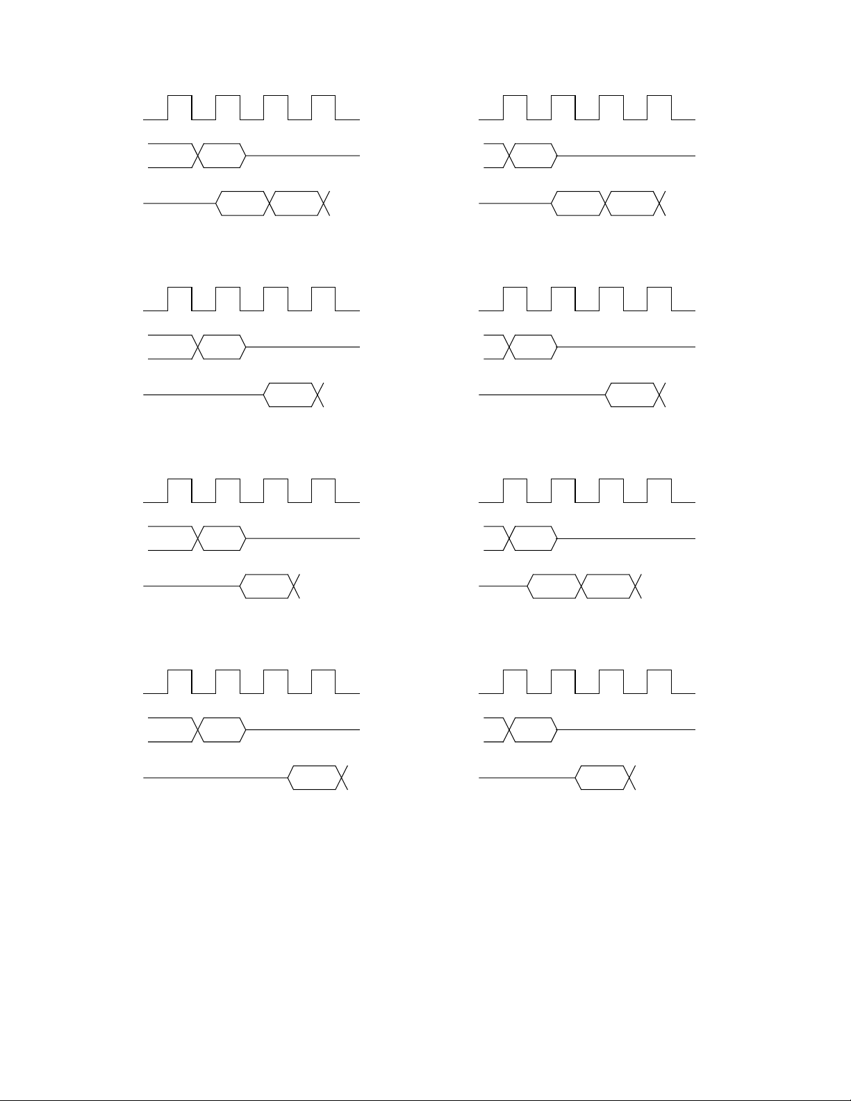
6: BSIO Interface
SCLK
SDIO
DATA OUT
SDIO
DATA IN
SCLK
SDIO
DATA OUT
SDIO
DATA IN
SCLK
RXD0 RXD0
WRPOL = 0, RDPOL = 0, CYCDELAY = 0
TXDn
RXD0
SCLK
SDIO
DATA OUT
SDIO
DATA IN
SCLK
SDIO
DATA OUT
SDIO
DATA IN
SCLK
TXDnTXDn
WRPOL = 1, RDPOL = 0, CYCDELAY = 0
TXDn
RXD0
WRPOL = 1, RDPOL = 0, CYCDELAY = 1WRPOL = 0, RDPOL = 0, CYCDELAY = 1
SDIO
DATA OUT
SDIO
DATA IN
SCLK
SDIO
DATA OUT
SDIO
DATA IN
TXDn
RXD0
WRPOL = 0, RDPOL = 1, CYCDELAY = 0
RXD0
SDIO
DATA OUT
SDIO
DATA IN
SCLK
SDIO
DATA OUT
SDIO
DATA IN
TXDn
RXD0
WRPOL = 1, RDPOL = 1, CYCDELAY = 0
TXDnTXDn
RXD0
WRPOL = 1, RDPOL = 1, CYCDELAY = 1WRPOL = 0, RDPOL = 1, CYCDELAY = 1
Figure 6.5 BSIO Bit timing options
In addition, the number of bytes/words to be sent and received in an operation is programmable between zero to
1023. Bit transfers will occur, on either the rising or falling edge, specified independently for read and write cycles
via the RDPOL and WRPOL bits. This has the option of a 1-cycle delay between write and read cycles controlled
by the CYCDELAY bit. The various bit timings possible are as shown in Figure 6.5 above.
In some applications, it may be necessary to send a Control Word at the start of an Operation. In order to support
this the BSIO provides a Page Mode in addition to the Standard Mode described above. The Control Word is held
in a separate 32-bit Parallel In / Serial Out Register. The CWORDSEL bit in the Mode Register selects between
38 GP4020 GPS Baseband Processor Design Manual

6: BSIO Interface
Standard and Page Modes, with the width of the Control Word being configurable between 2-bits and 32-bits via
the CW ORD bits.
In Standard Mode, the start of an Operation is defined as when the first word is written to the Read/Write Buffer. In
Page Mode, the start of an operation is defined as when the control word is written to the control word buffer.
In case of an Overflow condition (byte / word received when both words of the receive FIFO are full) an error bit
READERR in the Status Register is set. The new byte/word will not be shifted into the receive FIFO. An Under-flow
condition (byte / word required to be transmitted when both words of the transmit FIFO are empty) will result in the
WRITERR bit in the Status Register being set and the previous byte/word being sent.
6.3 BSIO Frequency Divider
The Frequency Divider allows the BµILD Bus clock B_CLK, to be divided down to a frequency of between B_CLK/2
to B_CLK/512, depending on the value selected by the SCLKFREQ bits in the Configuration Register. It consists of
a 9-bit Synchronous Counter and SCLK Enable Logic as shown in Figure 6.6 below.
Two outputs are provided: SCLK_INT (the serial output clock) and SCLKX2 (twice the frequency of SCLK_INT).
The frequency divider is disabled and held reset when no operation is currently in progress.
SCLKFREQ
OPERATION
B_CLK
9 BIT
COUNTER
SCLK_CTR
SCLKX2
SCLK
SCLK_EN
SCLKON
CPOL
SSEL
Figure 6.6 BSIO Frequency Divider
The division ratio of the counter is selected by the SCLKFREQ bits in the Configuration Register, and is in the
range 2^1 to 2^9, for SCLKFREQ = 0000 to SCLKFREQ = 1000 respectively. It is clocked by the Rising Edge of
B_CLK.
SCLK_EN, an output from the Sequencer, is used to enable or inhibit SCLK_INT. When SCLK_INT is in the idle
state (i.e. inhibited), its polarity will be configured for each of the slaves (SS0 & SS1) by means of the CPOL bits in
the Slave Select Register (High if CPOL = 1). The Timing Diagram for this is shown in Figure 6.7 below. Note that
if there is a change in the polarity of SCLK_INT, when selecting between two devices, the start of the first operation
can be delayed as required.
ENABLE
LOGIC
SCLK_INT
GP4020 GPS Baseband Processor Design Manual 39

6: BSIO Interface
SSEL
OPERATION
SS0 - SS1
SCLK_INT
Enable
Slave
01H
Enable
Slave
00H 02H 03H 03H
Note: ENPOL = 0000
00H
Enable
Slave
Enable
Slave
Figure 6.7 BSIO SCLK Polarity Timing
SCLKON in the Configuration Register allows SCLK_INT to be stopped during an Operation.
6.4 BSIO Slave Select Logic
The Slave Select Logic, as shown in Figure 6.8 below, provides the Slave enable signals. When a Slave device is
to be selected, the Sequencer enables the Slave Select Logic by means of the ext_sel signal.
The SSEL bits in the Configuration Register will select either SS0_OP or SS1_OP as shown in Table 6.1 below:
SSEL OP
000 SS0
001 SS1
010 Reserved
011 Reserved
100 Reserved
101 Reserved
110 Reserved
111 Reserved
Table 6.1 BSIO Slave Select Enable Configuration
In addition the ENPOL bits in the Slave Select Registers, configure the polarity of their corresponding select outputs
(i.e. active High or active Low), with ENPOL = '0' selecting an active Low.
SSEL
SLAVE
ENPOL
SELECT
SS0_OP - SS1_OP
LOGIC
ext_sel
Figure 6.8 BSIO Slave Select Logic
40 GP4020 GPS Baseband Processor Design Manual

6: BSIO Interface
6.5 BSIO Interrupt Control
The Active High INT output is provided to allow the BSIO to operate in an interrupt driven environment. The five
interrupt sources are the WRREADY, RDREADY, WRITERR and READERR bits in the Status Register and a
derivative of OPERATION, OPCOMP to denote the current operation has completed. They will be enabled by
writing (Logic = High to enable) to their corresponding enable bits in the Interrupt Control Register.
6.6 BSIO Write Buffer and Control Register
The Write Buffer consists of a two 32-bit transmit FIFO and a 32-bit transmit shift register and Control Logic as
shown in Figure 6.9 below.
CWORD_WR
32 bit bus
CWORD_EN
SELBYTE
TX_CLK
SHIFT_TX
TXWORD
TRFORMAT
32 bit bus
MUX AND
SHIFT
WRREADY
WRITERR
WFIFO_WR
SDO
BuILD Bus
END_OF_TX
BuILD Bus
CONTROL
WORD
REGISTER
FIFO
2 X 32 bits
Figure 6.9 BSIO Write Buffer and Control Register
Writing to the Read/Write Buffer loads the FIFO with a 32-bit word, whose valid bits will be shifted out serially via
the Transmit Shift Register. It should be borne in mind that not all the 32-bits would necessarily be sent since if byte
mode were selected by SELBYTE in the Transfer Register then they would be treated as four separate bytes to be
sent. However, if non-byte mode is selected then the TXWORD bits in the Transfer Register select the number of
bits in a word. Note that in this case the lower order bits make up the word, with the higher order ones being
redundant.
The Sequencer generates the signal TX_CLK, which forms the shift clock for serial data from the Shift Register,
with SHIFT_TX being the shift enable signal. It also asserts the END_OF_TX signal, after all the valid bits within a
32-bit Word have been shifted out.
WRREADY, a bit in the Status Register is set when the FIFO is ready to receive the next word, and is cleared when
the FIFO is full or when no more data is required to complete the current write operation. An Under-flow condition
i.e. a byte/word to be sent when the FIFO is empty, will result in the WRITERR bit in the Status Register being set
and the previous byte/word being sent. The WRITERR bit will be cleared by a read of the Status Register.
The TRFORMAT bits in the Slave Select Registers select between either a MSB or LSB first format (TRFORMAT =
High selecting MSB first) for each of the six slave devices. Note that in byte mode bit 7 of the byte would be the
MSB, whereas in word mode this would be its most significant bit.
The internal output WFIFO_WR will be set when the first word in an Operation is written to the FIFO, and is cleared
at the end of an Operation. Whilst in Standard Mode, it will be used to set the OPERATION bit in the Status
Register.
GP4020 GPS Baseband Processor Design Manual 41

6: BSIO Interface
When the Sequencer asserts CWORD_EN, the Control Word is shifted out at SDO prior to any data to be written
from the FIFO. CWORD_WR will be set when a Control Word is written to the Control Word Register, and will be
cleared at the end of an Operation. When in Page Mode, it will set the OPERATION bit in the Status Register.
6.7 BSIO Read Buffer
The Read Buffer consists of a Receive shift register, two 32-bit receive FIFOs and Control Logic as shown in Figure
6.10 below.
SELBYTE
RXWORD
TRFORMAT
SHIFT_RX
END_OF_RX
FIFO
2 X 32 bits
32 BIT BUS
RX_CLK
RECEIVE
SHIFT
REGISTER
SDI
RDREADY
RX_CLK
READERR
BuILD Bus
Figure 6.10 BSIO Read Buffer
Received data is shifted into the Receive shift register serially, and transferred to the FIFO in word / byte format,
from where it may be read as a 32-bit word. Note that like the Write Buffer, not all 32-bits in the Read FIFO will
necessarily be valid. When the SELBYTE bit in the Transfer Register selects byte mode, each 32-bit word is made
up of four consecutive bytes. However in non-byte mode, the RXWORD bits in the Transfer Register set the width
of the word that is to be received. Hence, the higher order bits that do not make up the word are redundant. For
example if a 20-bit Word were to be selected, then bdata<19:0> would make up the word, with bdata<31:20> not
being used.
Incoming serial data at SDI is shifted into the shift register by RX_CLK and the control signal SHIFT_RX both
generated by the Sequencer. Once the number of valid bits that make up a 32-bit word have been transferred into
the FIFO, an END_OF_RX signal generated by the Sequencer will set the RDREADY bit in the Status Register.
The RDREADY bit is cleared when the Read FIFO is empty.
As the FIFO is capable of storing two 32-bit words, it is possible to store the next word before the previous one has
been read.
If however a third word/byte were to be completely received whilst the FIFO is full the READERR bit in the Status
Register will be set, and further data will not be stored until the first word is read. READERR is cleared by a read of
the Status Register.
The TRFORMAT bits in the Slave Select Registers select between MSB and LSB formats, for each of the six slave
devices. Note that in byte mode bit 7 of each byte would be the MSB, whereas in Word mode this would be its most
significant bit.
6.8 BSIO Sequencer
The Sequencer consists of Read/Write Counters and Control logic as shown in Figure 6.11 below.
42 GP4020 GPS Baseband Processor Design Manual

OPERATION
sclk_int
SELBYTE
CWORD
CWORDSEL
TXWORD WRSIZE
WRITE
COUNTERS
shift_tx
end_of_tx
end_write
cword_en
wfifo_wr
cword_wr
end_write
end_readtri_state_en
6: BSIO Interface
OPERATION
end_write
sclk_int
SELBYTE
SSEL
CYCDELAY
RXWORD RDSIZE
READ
COUNTERS
shift_rx
end_of_rx
VALBYTES
end_read
SSLEAD
SSLAG
OPERATION
sclkx2
shift_rx
shift_tx
sclkx2
RWPOL
SSEL
SCLK
And
Ext
Select
SHIFT
CLOCKS
sclk_en
ext_sel
rx_clk
tx_clk
Figure 6.11 BSIO Sequencer
The Write Counters consist of a 5-bit binary counter to count the bit position within the currently transmitted control
or data word. There is also a 10-bit binary down counter. This is used to count the number of data words that
remain to be transmitted. At the start of an operation the counters are loaded with values determined by TXWORD
/ CWORD and WRSIZE in the Transfer and Mode Registers. After all the valid bits that make up a 32-bit word in
the Write FIFO have been shifted, the signal End_Of_Tx is asserted. End_Write is used to start the Read Counter,
after the last bit to be transmitted in the current operation has been shifted out of the Transmit Shift Register. When
the SELBYTE bit in the Transfer Register is set only byte-wide operations occur. If the CWORDSEL bit in the
Mode Register selects Page mode, the first word to be sent is the Control Word.
CWORD_EN acts as the shift enable signal for the Control Word Register, with CWORD in the Mode Register
selecting the width of the Control Word.
The Read Counters also consist of a 5-bit binary counter to count the bit position within the currently received data
word. Another 10-bit binary down counter counts the number of data words that remain to be received. At the start
of an operation, the counters are loaded with values determined by RXWORD and RDSIZE in the Transfer
Register. End_write, a signal from the Write Counter, is used to start the Read Counter, with CYCDELAY and
SSEL being able to select a 1 cycle delay for either SS0 or SS1. Shift_Rx, the control signal to the Read Buffer is
asserted when the first bit is to be read and de-asserted after the last bit has been shifted into the Receive shift
register. After all the valid bits that make up a 32-bit word in the RX FIFO have been shifted in, End_Of_Rx is
asserted, with end_read indicating the end of a complete read operation. The two status bits VALBYTES indicate
the number of bytes received. When the SELBYTE bit in the Transfer Register is set, only byte wide operations
occur.
The Operation bit in the Status Register is set when:
• the first word in an operation is written to the Write Buffer in Standard Mode,
• the Control Word is written in Page Mode.
The bit is cleared after the last bit of the current operation has been sent or received.
GP4020 GPS Baseband Processor Design Manual 43

6: BSIO Interface
The Sequencer enables SCLK and the Slave Select Logic by means of SCLK_EN and ext_sel respectively. The
bits SSLEAD in the Configuration Register select a delay between the external select being active and SCLK being
enabled of between 1 to 4 SCLK cycles. Similarly the bits SSLAG, select the delay between SCLK being stopped
and the external select being disabled of between 1 to 4 SCLK cycles.
RX_CLK and TX_CLK, the shift register clocks to the Read and Write Buffers are provided to allow data to be sent
or received at either the rising or falling edge of SCLK. RDPOL, WRPOL and SSEL select the clock polarity for read
and write cycles for each of the slave select outputs SS0 and SS1.
6.9 BSIO Registers
The BSIO uses nine separate registers. The GP4020 BSIO Base Address is 0xE000 7000.
Address Offset Regi ster Direction Function
0x000
0x004
0x008
0x00C
0x010
0x014
0x018 to 0x02C - -
0x030
0x034
0x038
0x03C
0x040 to 0xFFC
CONFIG
TRSFR
MODE
-
SLAVE0
SLAVE1
STATUS
INTC
RWBUF
CWBUF
-
Read/W rite Configuration Register
Read/W rite Transfer Control Information
Read/W rite Mode Register
-
Read/W rite Slave Select 0
Read/W rite Slave Select 1
Read Status Register
Read/W rite Interrupt Control
Read/W rite Read Write Buffer
Read/W rite Control W ord Buffer
-
Table 6.2 BSIO Register Map
Reserved
Reserved
Reserved
All registers are addressable as 32-bit locations only
6.9.1
BSIO Configuration Register - CONFIG - Memory Offset 0x0000
Bit Mnemonic Description Reset
31:18
17:15 SSEL Slave Select. Selects slave as follows:
14
13
12 CONFSDIO Configure SDIO. A High c onfigures SDIO as an Open Drain
11 CONFSCLK
Reserved
SSEL=000 SS0
SSEL=001 SS1
ALL OTHERS Reserved
Reserved
Reserved
Output, whereas a Low configures it as a CMOS output.
Configur e SCLK. A High configures SCLK as an Open Drain
output, whereas a Low configures it as a CMOS output.
Value
R/W
All = 0 R
000 R/W
0R/W
0R/W
0R/W
0R/W
44 GP4020 GPS Baseband Processor Design Manual

6: BSIO Interface
Bit Mnemonic Description Reset
10:7 SCLKFREQ
6:5 SSLAG SS LAG time. Period between SCLK being stopped, and the
4:3 SSLEAD SS LEAD time. Period between the external select being active,
2SCLKON
1:0
SCLK Frequency. S elect the frequenc y of SCLK, between
B_CLK/512 to B_CLK/2 in nine increments.
SCLKFREQ = 0000 selects B_CLK/2,
SCLKFREQ = 0001 selects B_CLK/4,
SCLKFREQ = 0010 selects B_CLK/8
Until …
SCLKFREQ =1000 selects B_CLK/512.
If SCLKFREQ > 1000, B_CLK/512 is selected.
external select being disabled.
Programmable between 1 to 4 SCLK cycles, with bit settings ‘00’
to ‘11’ respectively.
and SCLK being enabled. Programmable between 1 to 4 SCLK
cycles, with bit settings ‘00’ to ‘11’ respectively.
SCLK ON. When H igh, SCLK is ON, during an operation, when
Low it is OFF.
Reserved
Value
0000 R/W
00 R/W
00 R/W
1R/W
00 R
R/W
Table 6.3 BSIO Configuration Register
NOTE: If CONFSDIO is set High, to configure SDIO as Open Drain (i.e. Tx 0 = driven low, Tx 1 = tristate) then the
SDIO pin will remain driven low if the last bit transmitted is '0'. Therefore, to do a Transmit followed by a
Receive, you need to ensure that the last bit transmitted from the SDIO port on the GP4020 is a “1” (i.e.
High), otherwise the SDIO will only read “0” (i.e. Low).
6.9.2
BSIO Transfer Register - TRSFR - Memory Offset 0x0004
Bit
No.
31
30:26 RXWORD
25:21 TXWORD
20 SELBYTE Select Byte. When High selects B yte Data Transfer, when Low selects
19:10 WRSIZE Write Size. When written configures the number of bytes/words to be s ent
Mnemonic Description Reset
Reserved
RX Word Width: When SELBYTE = Low, the size of the RX W ord can be
configured from 2- to 32-bits.
RXWORD = 00000 or 00001 selects a width of 2, with R XWORD = 11111
selecting a width of 32.
Note only the least signific ant bits selected make up the Word, with the
most significant bits not used.
These bits are ignored when SELBYTE = High.
TX Word Width: W hen SE LBYTE = Low, the size of the TX W ord can be
configured from 2- to 32-bits.
TXWORD = 00000 or 00001 select a width of 2, with TXWORD = 11111
selecting a width of 32.
Note only the least signific ant bits selected make up the Word, with the
most significant bits not used.
These bits are ignored when SELBYTE = High.
Word.
in current oper ation.
With WRSIZE = 0000000000 for bytes/words = 0 to WRSIZE =
1111111111 for bytes/words = 1023
WRREM W rite Remaining. When read returns the number of bytes/words remaining
to be sent in the current oper ation.
Value
0R
11111 R/W
11111 R/W
1R/W
00000
00000
00000
00000
R/W
W
R
GP4020 GPS Baseband Processor Design Manual 45

6: BSIO Interface
Bit
No.
9:0 RDSIZE
Mnemonic Description Reset
RDREM Read Remaining. When read returns number of bytes/ words remaining to
Read Size. W hen writt en configures the number of bytes/words to be read
in the current operation.
With RDSIZE = 0000000000 for bytes/words = 0 to RDSIZE =
1111111111 for bytes/words = 1023
be received in the current operation.
Table 6.4 BSIO Transfer Register
Value
00000
00000
00000
00000
R/W
W
R
6.9.3
BSIO Mode Register - MODE - Memory Offset 0x0008
Bit
No.
31:6
5 CWORDSEL Control Word Select: When High s elects Page mode,
4:0 CW ORD
Mnemonic Description
Reserved
when Low selects Standard mode.
Control Word Width: These bits configur e the width of the
Control Word between 2-bits and 32-bits.
CWORD = 00000 or 00001 selects a width of 2, whilst
CWORD = 11111 selects a width of 32.
Table 6.5 BSIO Mode Register
6.9.4
BSIO Slave Select Registers - SLAVE0, SLAVE1 - Memory Offset (SLAVE0 = 0x0010, SLAVE1
= 0x0014)
Bit
No.
31:6
5 TRFORMAT Transfer Format. A High selects MSB as the first bit, with a Low selecting
4CYCDELAY
3 CPOL Clock Polarity. When Low, the SCLK idle state is Low, when High the SCLK
2WRPOL
1 RDPOL
0 ENPOL Enable Polarity. Sets the polarity of the Slave Select output as either ac tive
Mnemonic Description Reset
Reserved
LSB.
Cycle Delay. Allows the insertion of a 1-c ycle delay, between write and read
cycles. A High s elects a delay and a LOW no delay.
idle state is High. N ote that if two Slaves have different idle states, then the
start of an operation can be delayed as required.
Write Polarity. This bit selects either a rising or falling edge of SCLK for write
cycles. A High selects a Rising edge, with a Low selecting a Falling edge.
The edge is with respect to the BSIO block, not the slave. Hence WRPOL
selecting a rising edge configures the BSIO to gener ate output data
transitions on the rising edge of SCLK, to be latched by the current slave on
the falling edge.
Read Polarity. This bit selects either a ris ing or falling edge of SCLK for read
cycles. A High selects a Rising edge, with a Low selecting a Falling edge.
The edge is with respect to the BSIO block, not the slave. Hence RDPOL
selecting a rising edge configur es the BSIO to register input data on the
rising edge of SCLK, which has been generat ed by the current slave on the
falling edge.
Low or active High.
A Low configures the corresponding output as active Low, with a High
configuring it as active High.
Table 6.6 BSIO Slave Select Register
Reset
Value
All = 0 R
0R/W
11111 R/W
R/W
R/W
Value
All = 0 R
0R/W
0R/W
0R/W
0R/W
0R/W
0R/W
46 GP4020 GPS Baseband Processor Design Manual

6.9.5 BSIO Status Register - BSIO_STAT - Memory Offset - 0x0030
6: BSIO Interface
Bit
No.
31:8
7OPCOMP
6 OPERATION Operation: Set at start of operation, by first word written to
5 WRITERR Write Error: Set when an under-flow occurs in the Write
4 READERR Read Error. Set when an overflow occurs in the Read Buffer.
3:2 VALBYTES Valid Bytes. Number of Valid bytes to be read, from the Read
1 RDREADY R ead Buffer Ready. Set when Read buffer contains at least
0 WRREADY
Mnemonic Description Reset
Reserved
Operation Complete: S et once current operation has
completed. Cleared by Read of Status Reg.
Write Buffer in Standard Mode or by writing the Control Word
in Page Mode. Cleared at end of operation after last word
sent or received.
Buffer.
Cleared by Read of Status Register
Cleared by read of Status Register.
Buffer.
one valid word. Clear ed when buffer is empt y.
Write Buffer Ready. Sets whenever the W rite Buffer is ready
to store next 32-bit word, and more words are required to
complete the current transmit operation. Cleared when buffer
is full or all words have been transmitted.
Table 6.7 BSIO Status Register
6.9.6 BSIO Interrupt Control Register - INTC - Memory Offset - 0x0034
Value
R/W
All = 0 R
0R
0R
0R
0R
00 R
0R
0R
Bit
No.
31:8 -
7 OPCOMPEN Operation Complete Enable. Active High interrupt Enable
6-
5 WRITERREN W rite Error Enable. Active High Interrupt Enable for the
4 READERREN R ead Error Enable. Active High Interrupt Enable f or the
3:2
1 RDREADYEN Read Ready Enable. Active High Interrupt Enable for the
0 WRREADYEN Write Ready Enable. Active High Interrupt Enable for the
Mnemonic Description Reset
Reserved
for the OPCOMP bit in the Status Register.
Reserved
WRITERR bit in the St atus Register
READERR bit in the Status Register
Reserved
RDREADY bit in the Status Register
WRREADY bit in the Status Register
Table 6.8 BSIO Interrupt Control Register
Value
R/W
All = 0 R
0R
0R
0R/W
0R/W
00 R
0R/W
0R/W
GP4020 GPS Baseband Processor Design Manual 47

6: BSIO Interface
6.9.7 BSIO Read/Write Buffer Register - RWBUF - Memory Offset - 0x0038
6.9.8
Bit
No.
31:0 RWBUFF 32-bit Read/W rite buffer, f or word to be sent and received.
Mnemonic Descript ion Reset
Data Transfer can be either byte oriented, or based on a
Word Width configurable between 2- and 32-bits, for the
Read and Write Buffers. When configured as a Word, only
the selected number of lower order bits are employed, with
the remaining higher order bits not used. This is
implemented as a 2 Word by 32-bit FIFO, for both words to
be sent and those received.
Table 6.9 BSIO Read/Write Buffer Register
BSIO Control Word Buffer Register - CWBUF - Memory Offset - 0x003C
Bit
No.
31:0 CONT 32- bit Control W ord to be sent. This will be the first word
Mnemonic Descript ion Reset
sent in an operation, if the CWORDSEL bit, in the Mode
Register is set. The width of this word is c onfigurable from
2- to 32- bits via the CWORD bits in the Mode Register.
Table 6.10 BSIO Control Word Buffer Register
Value
R/W
All = 0 R/W
R/W
Value
All = 0 R/W
48 GP4020 GPS Baseband Processor Design Manual

7: 12-Channel Correlator
7 12-CHANNEL CORRELATOR (CORR)
7.1 Introduction
The 12-Channel Correlator forms the GPS-specific module of the GP4020 GPS Baseband Processor. It comprises
12 parallel Spread-spectrum signal tracking modules, including Carrier offset mixers, C/A code generators and
mixers, and 1ms Accumulate and Dump registers. Figure 7.1 below shows a block diagram of the correlator. It
consists of the following blocks:
7.1.1 Clock Generator
The Clock Generator block divides the frequency of the 40MHz master clock, which is generated by the System
Clock Generator (refer to section 14), by 6 or 7 to give the internal multi–phase set of clocks. The SAMPCLK pin
(pin 63 (100-pin package)) is an output giving a 4:3 mark–to–space ratio clock at 40 MHz / 7 (= 5·714MHz).
7.1.2 Timebase Generator
The Timebase Generator produces three important timing signals: ACCUM_INT, TIC and MEAS_INT. ACCUM_INT
is an interrupt provided to control data transfer between the correlator accumulators and the microprocessor. It may
be detected by means of the ACCUM_INT output or by reading the ACCUM_STATUS_A register (where bit 15 is a
flag indicating that ACCUM_INT has occurred since the previous read of this register). ACCUM_INT is cleared by
reading ACCUM_STATUS_A. After power–up this interrupt occurs every 505.05µs. The Interrupt period can
subsequently be changed by:
• toggling the INTERRUPT_PERIOD bit of the SYSTEM_SETUP register, or
• writing directly to the PROG_ACCUM_INT register.
TIC is an internal signal with a default period of 99999.90µs. It is used to latch measurement data (Epoch count,
Code phase, Code DCO phase, Carrier DCO phase and Carrier cycle count) of all 12 channels at the same instant.
Its period can subsequently be changed, by writing to the PROG_TIC_HIGH and PROG_TIC_LOW registers, or
toggling the FRONT_END_MODE bit of the SYSTEM_SETUP register.
MEAS_INT is a signal derived from the TIC counter. It may be used by the microprocessor as a software module
switching interrupt either by using the MEAS_INT output or by reading the ACCUM_STATUS_B or
MEAS_STATUS_A registers. MEAS_INT is activated at each TIC and 50 ms before each TIC provided the TIC
period is greater than 50 ms. If the TIC period is less than 50 ms, MEAS_INT is activated only at each TIC. It is
cleared by reading either the ACCUM_STATUS_B or MEAS_STATUS_A register, depending upon the
MEAS_INT_SOURCE bit of the SYSTEM_SETUP register.
GP4020 GPS Baseband Processor Design Manual 49

7: 12-Channel Correlator
UIM BUS
(To / from Firefly MF1)
CONTROL
A<9:2>
SYSTEM
MULTI- PHASE CLOCKS
STATUS
REGISTERS
DATA BUS
INTERFACE
D<15:0>
ADDRESS
DECODER
UIM INTERFACE
STATUS BITS
32 BIT BUS
MODULE 0
TRACKING
TIC
MODULE 1
TRACKING
TIC
MULTI- PHASE CLOCKS
MODULE 2
TRACKING
TIC
MULTI- PHASE CLOCKS
MODULE 3
TRACKING
TIC
SELECTS
REGISTER
TRACKING
MODULE 11
TIC
MULTI- PHASE CLOCKS
MULTI- PHASE CLOCKS
TIC
MAG0
SIGN0 &
LATCHED
MAG1
SIGN1 &
LATCHED
CLOCK
GENERATOR
M_CLK
(from SCG)
SAMPCLK
SAMPLE LATCH
MAG0
SIGN0 /
To / From
MAG1
SIGN1 /
RF Front End
TIC
TIMEBASE
MEAS_INT
To Firefly
RAW
TIMEMARK
GENERATOR
TIC
ACCUM_INT
To 1PPS
INTC & PCL
Timemark
GENERATOR
RAW
TIMEMARK
RELOAD TIC
Generator
CLK100KHz
Figure 7.1 12-Channel Correlator Block Diagram
50 GP4020 GPS Baseband Processor Design Manual

7: 12-Channel Correlator
7.1.3 Raw-Timemark Generator
The Raw Timemark generator generates two essential signals:
1) CK100kHz. This 100kHz clock is derived from M_CLK. This clock is only as accurate as the receiver TCXO
attached to the RF front-end, and hence cannot be re-synchronised to any GPS system timing. This signal can
be accessed from the Peripheral Control Logic (PCL) block.
2) Raw Timemark. This is a one Pulse-Per-Second (1PPS) signal which is derived the Multiphase Clock and the
TIC signal from the Timebase generator.
The Raw Timemark signal can be aligned to UTC (Universal Time Co-ordinated) by means of dynamic software
skewing of the TIC period within the Timebase Generator. The resolution of the TIC skewing is limited to 175ns
minimum. Improved alignment resolution can be achieved in conjunction with an external block of circuitry, the
1PPS Timemark Generator.
There are two methods of generating the Raw Timemark signal. In both cases TIMEMARK rising edges are
generated coincident with the rising edges of TIC. Therefore, for TIMEMARK to be aligned with UTC, TIC must be
aligned with UTC. This can be done by modifying the TIC period for a single TIC cycle, then setting it back to its
original value, thus slewing the phase of TIC. The alignment to UTC can also be performed independently of TIC
slewing by an independent delay counter within the external 1PPS Timemark generator.
Raw Timemark can be generated using two methods:
1) Set "FREE_RUN_TIMEMARK" (Bit 1 in TIMEMARK_CONTROL register) to ‘0’ and by setting the
ARM_TIMEMARK bit (Bit 0); the next TIC will generate a rising edge at RAW_TIMEMARK and clear the
ARM_TIMEMARK bit.
2) Set "FREE_RUN_TIMEMARK" to '1', and set the number of TICs per RAW_TIMEMARK period in the
"FREE_RUN_RATIO" bits of the register (Bits 2 to 6). In this instance, a RAW_TIMEMARK output pulse is
generated automatically every "FREE_RUN_RATIO" TICs automatically.
Further details of producing 1PPS Timemark are covered within Section 15 "1PPS TIMEMARK GENERATOR" on
page 149 for more information.
7.1.4 Status Registers
There are four status registers (ACCUM_STATUS_A, _B, _C and MEAS_STATUS_A). These contain flags
associated with the accumulated and measurement data held on each of the 12 channels. Some system level
status bits also appear in these registers.
7.1.5 Sample Latches
The Sample Latches synchronise data from the front end to the internal SAMPCLK. The down converted satellite
signal can be sampled at the output of the front end by SAMPCLK. This data is then input to the 12-channel
correlator as 2-bit data on the SIGN0, MAG0, where it is resampled at the next rising edge of SAMPCLK. These
signals are then distributed to the 12 tracking modules. When a GP2015 or GP2010 front end is used, the data
represents a band–limited signal at an IF centred on 4.309MHz. The IFOUT will alias to a 1.405MHz digitised IF, by
sampling the 4.309MHz signal at a rate of 5.714MHz.
7.1.6 Address Decoder
The Address Decoder performs address decoding for the correlator.
7.1.7 Bus Interface
The Bus Interface controls the transfer of data between the external 16-bit wide data bus and the internal 32-bit
data bus. Apart from the code and carrier DCO increment values, all data transfers are 16-bits wide. Write
GP4020 GPS Baseband Processor Design Manual 51

7: 12-Channel Correlator
operations to the code and carrier DCO’s are 32-bit data transfers, in which the High 16-bit word must be written
immediately before the low 16-bit word. Note that the write cycle to write cycle delay of 300ns referred to in the
Microprocessor Interface does not apply between the first and second write cycles for 32-bit DCO data transfers.
For further information, refer to Section 7.5 "12 Channel Correlator Interface Timing" on page 63.
7.1.8 UIM Interface
The UIM Interface performs data conversion and re-timing between the 12-channel correlator (clocked with the
M_CLK signal from the System Clock Generator), and the Up Integration Module Bus (UIM bus), clocked by
BµILD_CLK. For further information, refer to Section 11 "MEMORY PERIPHERAL CONTROLLER (MPC)" on page
109.
7.2 Tracking Modules
The Tracking Modules are 12 identical signal-tracking channels numbered CH0 to CH11, each with the block
diagram shown in Figure 7.2 below. These blocks generate the data used to track the satellite signals. There is no
overwrite-protection mechanism on this data. For further information, refer to Section 7.4 "Controlling the 12
Channel Correlator" on page 59.
Each Tracking Channel can be individually programmed to operate in either UPDATE or PRESET mode. Update
mode is the normal mode of operation. PRESET mode is a special mode of operation where writes to certain
registers are delayed until the next TIC to allow synchronisation of registers and pre-setting of the code DCO
phase. For further information, refer to Section 7.4.9 "PRESET Mode" on page 61.
SIGN0
AND
MAG0
SIGN1
AND
MAG1
SOURCE
SELECTOR
SOURCE &
MODE
SELECT
Q
LO
CARRIER
DCO
I
LO
CARRIER
CYCLE
COUNTER
DUMP CONTROL SIGNAL
16 BIT ACCUMULATE AND
DUMP - Q TRACKING
16 BIT ACCUMULATE AND
DUMP - Q PROMPT
C/A CODE
GENERATOR
CODE PHASE
COUNTER
16 BIT ACCUMULATE AND
DUMP - I PROMPT
16 BIT ACCUMULATE AND
DUMP - I TRACKING
CODE
SLEW
CODE
DCO
EPOCH
COUNTERS
DATA BUS
DUMP
Figure 7.2 Tracking Module Block Diagram
52 GP4020 GPS Baseband Processor Design Manual

7: 12-Channel Correlator
The individual sub–blocks in the tracking modules are:
7.2.1 Carrier DCO
The Carrier DCO, which is clocked at the SAMPCLK frequency, is used to synthesise the digital Local Oscillator
signal required to bring the input signal to baseband in the mixer block. It must be adjusted away from its nominal
value to allow for Doppler shift and reference frequency error.
When used with the GP2015/GP2010 the nominal frequency of this signal is 1.405396825 MHz (with a resolution of
42.57475 MHz) and is set by loading the 26-bit register CHx_CARRIER_DCO_INCR. This very fine resolution is
needed so that the DCO will stay in phase with the satellite signal for an adequate time.
The Carrier DCO Phase cannot be directly set, but must be adjusted by altering the frequency. The Carrier DCO
outputs are 4 level, 8 phase sinusoids with the following sequences over one cycle:
+2
+1
I
-1
-2
+2
+1
Q
-1
-2
Figure 7.3 Waveform outputs from Carrier DCO I & Q LO (sinewaves are a guide only)
Destination Arm Sequence
I
LO
Q
LO
-1 +1 +2 +2 +1 -1 -2 -2
+2 +2 +1 -1 -2 -2 -1 +1
Table 7.1 12-channel Correlator Carrier DCO outputs
As the clock to the DCO is normally less than 8 times the output frequency, not all phases are generated in every
cycle. With a typical clock frequency of 5.714 MHz and an output frequency of 1.405 MHz, there are only approx. 4
phases per cycle. These will slide through the cycle as time progresses to cover all values.
7.2.2 Code DCO
The Code DCO is similar to the Carrier DCO block. It is also clocked at the SAMPCLK frequency, and synthesises
the oscillator required to drive the code generator at twice the required chipping rate. The nominal frequency of the
GP4020 GPS Baseband Processor Design Manual 53

7: 12-Channel Correlator
output is 2.046 MHz, to give a chip rate of 1.023 MHz and is set by loading the 25-bit register
CHx_CODE_DCO_INCR.
It is programmed with a resolution of 85·14949 mHz when used with a GP2015/GP2010 front end. The very fine
resolution is again needed to keep the DCO in phase with the satellite signal. The Code DCO Phase can only be
set to the exact satellite phase in PRESET mode. In Update mode, it must be aligned with the satellite phase by
adjusting its frequency.
7.2.3 Carrier Cycle Counter
The Carrier Cycle Counter is 20-bits long, and keeps a count of the number of cycles of the Carrier DCO between
TICs. This is not needed for a basic navigation system but may be used to measure the range change (delta–
range) to each satellite between TICs. The delta ranges can be used to smooth the code pseudo–ranges. For finer
detail the Carrier DCO phase may also be read at each TIC to give the fractional part of the cycle count or delta–
range.
7.2.4 C/A Code Generator
The C/A Code Generator generates the selected Gold code for:
i) a GPS satellite (1 to 32),
ii) a ground transmitter (pseudolite, 33 to 37),
iii) an INMARSAT–GIC satellite (201 to 211),
iv) an INMARSAT-WAAS satellite (120 to 138)
v) a GLONASS satellite.
A Gold code is selected by writing a specific pattern of 10-bits to the CHx_SATCNTL register, or by setting the
GPS_NGLON bit to Low for the GLONASS code. Two outputs are generated to give both a PROMPT and a
TRACKING signal. The TRACKING signal can be set to one of four modes: EARLY (one half chip before the
PROMPT signal), LATE (one half chip behind), DITHERED (toggled between EARLY and LATE every 20ms) or
EARLY–MINUS–LATE (the signed difference). The output code is a sequence of +1’s and –1’s for all code types
except EARLY–MINUS–LATE where the result can also be a '0'. To avoid having an unused LSB in the
accumulators, the values in EARLY–MINUS–LATE mode are halved from the +2, 0, –2 that results from the
calculation (+1 or –1) – (+1 or –1) to +1, 0, –1. This must be considered when choosing thresholds in the software,
as the correlation results will be exactly half of the values otherwise expected.
At the end of every code sequence (1023 chips in GPS mode or 511 chips in GLONASS mode), a DUMP signal is
generated to latch the Accumulated Data for use by the signal tracking software. Each channel is latched
separately, as the satellite signals are not received in phase with each other.
The nature of GLONASS signals is that they are modulated with the same PRN Gold Code, but are separated in
the frequency domain (1597MHz to 1617MHz). Navstar GPS signals are modulated with different PRN Gold
Codes, but are transmitted on the same frequency (L1 = 1575.42MHz).
For the GP4020 to effectively de-modulate GLONASS signals, it would ideally need to have a separate set of RF
signal inputs for each correlator channel, in order for it to differentiate between the different frequencies used by
each GLONASS satellite. Since this facility is NOT available, the GP4020 cannot be used effectively to decode a
constellation of GLONASS signals.
Although the GP4020 contains a C/A code generator that can be used to demodulate GLONASS signals, the
GP4020 does NOT have a sufficiently wide Doppler-offset compensation range to allow it to be used effectively for
GLONASS. (The GLONASS code can be selected by setting the GPS_NGLON bit in CHx_SATCNTL to '0'). The
total frequency offset, which the carrier DCO can cope with, is ±2.857MHz. This means that the GP4020 12channel correlator will NOT be able to deal with the complete range of GLONASS signals, unless they are mixed
separately down to a digital IF of approx. 1.4MHz.
The GP1020, also available from Zarlink Semiconductor, has 10 separate sets of SIGN / MAG inputs from RF frontend devices, which can be configured to connect independent to any of 6 correlator channels, making this device
more suitable for GLONASS applications. Contact your regional Zarlink sales office for more information.
54 GP4020 GPS Baseband Processor Design Manual

7: 12-Channel Correlator
7.2.5 Carrier Mixers
The Carrier Mixers multiply the digital input signal by the Carrier DCO digital local oscillator to generate a signal at
baseband. Both the I and Q Carrier DCO phases are directed to the appropriate mixers. The mixing of the Carrier
DCO outputs with the input signal that produces a baseband signal, which can have the values ±1, ±2, ±3 and ±6.
7.2.6 Code Mixers
The Code Mixers multiply the I and Q baseband signals from the Carrier Mixers with both the PROMPT and
TRACKING local replica codes to produce four separate correlation results. The correlation results are passed to
the Accumulate and Dump blocks for integration.
7.2.7 Accumulate and Dump
The Accumulate and Dump blocks integrate the Mixer outputs over a complete code period of nominally 1ms.
There are four separate 16-bit accumulators for each channel. These represent the correlation of the I and Q
signals with the PROMPT and TRACKING codes, over the integration period. There is no overwrite protection
mechanism on these registers so the data must be read before the next DUMP.
7.2.8 Code Phase Counter
The Code Phase Counter counts the number of half–chips of generated code and stores this value in the
CHx_CODE_PHASE register on each TIC.
7.2.9 Code Slew Counter
The Code Slew Counter is used to slew the generated code by a number of half chips in the range 0 to 2047. In
Update mode, the slew occurs following the next DUMP. In PRESET mode, it occurs at the next TIC. All slew
operations are relative to the current code phase. The Code Slew counter must be written to, each time a slew is
required. During the slewing process, the accumulators for the channel being slewed are inhibited so that the first
result is valid. If a slew is written while a channel is disabled, the slew will occur as soon as the channel is enabled.
7.2.10 Epoch Counter
The Epoch Counters keep track of the number of code periods over a 1-second interval. This is represented by a 5bit word for the number of 1 ms integration periods (0 to 19), plus a 6-bit word containing the number of 20 ms
counts (0 to 49). The Epoch Counters can be pre-loaded to synchronise them to the data stream coming from the
satellite. This value will be transferred immediately to the counter when in Update Mode, or after the next TIC if in
PRESET Mode.
The Epoch Counter values are latched on each TIC into the CHx_EPOCH register. In addition, the instantaneous
values are available from the CHx_EPOCH_CHECK register.
7.3 Software Requirements
The GP4020 12-channel correlator can be operated in different ways dependent upon the GPS Receiver system
required by the user. So to accommodate this and to allow dynamic adjustment of loop parameters, the GP4020
12-channel correlator has been designed to use software for as many functions as possible. This flexibility means
that the device cannot be used without a microprocessor closely linked to it. Since a processor is always needed to
convert the output of the 12-channel correlator into useful information, this is not a significant limitation.
The software associated with the 12-channel correlator can be divided into two separate modules:
1) Acquire and track satellite signals to give pseudo-ranges;
GP4020 GPS Baseband Processor Design Manual 55

7: 12-Channel Correlator
2) Process pseudo-ranges to give the navigation solution and format it in a form suitable for the user.
In order for a Navigation Solution to be achieved, all of the pseudo-ranges must have exactly the same clock error.
This clock error can then be removed iteratively to give real ranges if sufficient satellites are tracked (three if the
height is known, otherwise four). This need for exact matching of timing errors explains the need for all of the
complicated synchronisation between all 12-channels of the correlator.
The following relates only to the signal processing aspects of the software, to acquire and track signals from up to
twelve satellites and to obtain the pseudo-ranges and the navigation message. The operation of the navigation
software is not dependent on the details of the correlator, and so does not need to be included in this data sheet.
A pair of on-chip interrupt time-base signals is provided to help implement a data transfer protocol between the
microprocessor and the 12-channel correlator at fixed time intervals:
1) ACCUM_INT. Used to interrupt the microprocessor to retrieve Accumulated data (1.023ms worth) - period of
interrupt normally less than 1ms.
2) MEAS_INT. Used to interrupt the microprocessor to retrieve Measurement data that occurs once every TIC
(approx. 100ms period).
These interrupts can be used to achieve instant response from the microprocessor via an Interrupt Service Routine.
Otherwise software-based polling will be needed; the choice is set by the application. If the ACCUM_INT interrupt is
used, and perhaps also if polling is used, the data transfer rate is about twice the correlation result rate for each
channel, so many transfers will not give new data. Bus use can be reduced by examining the status registers
before each transfer to see if new data is available and then only reading the data if it is useful.
It is important to note that the timing of each of the correlator channels will be locked to its own incoming signal and
not to each other or to the microprocessor interrupts, so new data is generated asynchronously. The sampling
instant of measurement data of all channels however is common to give a consistent navigation solution.
In order to acquire lock to the satellites as quickly as possible, the data from the last fix should be stored as a
starting point for the next fix. It is also useful to make use of the embedded real-time clock on the chip to give a
good estimate of GPS time for the next fix. The navigation solution can be used to measure clock drift and calculate
a correction for the clock to overcome ageing. The user's location (or a good estimate of it) along with the Almanac
and the correct time will indicate which satellites should be searched for. These may be used to find an estimate of
Doppler effects, while the previous clock error is the best available estimate of the present clock error. If this
information is not available then the receiver must scan a much wider range of values, which will greatly increase
the time to lock. The satellite Clock Correction and Ephemeris are needed for the navigation solution. If a recent set
of this information is held in memory, the calculations may begin as soon as lock is achieved and not need to wait
for the Satellite Navigation message re-transmission (18 to 36 seconds).
The 12-channel correlator on the GP4020 contains four different types of registers:
• Control Registers that are used to program functions of the device.
• Status Registers that provide a status indication of the process taking place in the device.
• Accumulated Data Registers that provide the results of correlation with the C/A code every millisecond. This
is the raw data used to acquire and track satellite signals.
• Measurement Data Registers which latch the carrier DCO phase, carrier cycle count, code DCO phase, 1
millisecond epoch, and the 20 millisecond epoch count at every 9.09 or 100 milliseconds interval. This is the
raw data used to compute pseudorange.
7.3.1
The spectrum of each Navstar GPS satellite signal is spread-spectrum modulated using 1023 chip Gold codes.
This causes the satellite signals seen by a GPS receiver to be so weak that they are buried in the noise and can
only be detected by correlation. The GPS signal power at a GPS receiver antenna is typically approx. -130dBm,
whereas the noise in the GPS signal band (2.046MHz wide) is approx. -111dBm at room temperature. To correlate
56 GP4020 GPS Baseband Processor Design Manual
Software Sequence For Acquisition

7: 12-Channel Correlator
the received signals therefore, a locally generated code must be chosen to precisely match the spreading code
type, rate, and phase.
This pattern is then multiplied bit-by-bit with the incoming data stream and the results integrated over the code
length to recover the signal.
The process of signal acquisition is simply the matching of receiver settings to the actual signal values. To make
matters more complicated the satellite carrier frequency is shifted a little by the Doppler effect due to the motion of
the satellite. The user clock will drift randomly, and (in most situations) the signal-to-noise-ratio (SNR) is poor for
some satellites. Therefore, the software must be 'wide-band' to find the signal and 'narrow-band' to reduce noise,
leading to very different programs in different applications. For all tracking channels, the signal processing software
needs the following sequence of activities:
1. Program CHx_SATCNTL register to select the desired GPS Gold code (PRN number) for the selected
satellite and also select the code type for the mode of the correlator tracking arm. It is often best when in
acquisition mode to fix the tracking arm to Dithering Mode (alternate 'Early' and 'Late') and do a search in two
phases at once. Then switch the tracking arm to a tracking mode once a satellite is found.
2. Program CHx_CARRIER_DCO_INCR_HIGH and CHx_CARRIER_DCO_INCR_LOW registers. The values
programmed into these two registers are concatenated and are used to set the local oscillator frequency for the
digital mixing performed in the 12-channel correlator. This brings the incoming 2-bit digitised signal from the RF
Front-end down to baseband. The value to be programmed is equal to the nominal local oscillator frequency
plus the estimated Doppler shift compensation plus the estimated user clock frequency drift compensation.
3. Program CHx_CODE_INCR_LO and CHx_CODE_INCR_HI. The value to be programmed in these registers
represents twice the nominal chipping rate of the C/A code (2.046 MHz); in addition, if desired, a small
compensation for the Doppler shift and user clock frequency drift.
4. Release the tracking channel reset by programming the RESET_CONTROL register with the proper value.
This will cause the correlation process to start.
5. Obtain accumulated data from Accumulated Data Register readings. Several consecutive readings on the
same tracking channel can be added to increase, at will, the integration period of the correlation.
6. Decide if the GPS signal has been found by comparing the correlation result with a threshold. If found then
jump to a signal pull-in algorithm. Note that both in-phase and phase quadrature accumulated data have to be
considered since at this tim e, the carrier DCO local oscillator phase is not necessarily in phase with the
incoming GPS signal.
7. If the GPS signal has not been found, a new trial has to be made with different carrier DCO, code DCO, or
gold code phase programming. Typically, both DCOs would be held constant while the Gold code phase is
varied to try all of the 2046 half chip positions possible. The carrier DCO would then be programmed with
slightly different values and the Gold code phase positions would again be scanned. The Gold code phase is
varied by programming the CHx_CODE_SLEW register and can be varied by increments of half a code chip.
8. Once the GPS signal has been found, the code phase alignment, the carrier phase alignment and the
Doppler and user clock bias compensations are still coarse. The code phase alignment is only within a half
code chip, the carrier DCO is not in phase with the incoming signal and infrequency is still in error by up to the
increment used for successive trials.
The signal processing software must next use a pull-in algorithm to refine these alignm ents. There are many
suitable types of algorithm to choose from, such as:
i) successive small steps until the error is too small to matter, like an analogue PLL;
ii) using more complicated signal processing to estimate the errors and jump to a much better set of values.
The signal pull-in algorithm will then program CHx_CARR_INCR_LO / HI registers with more values that are
accurate for the Carrier DCO. Corrections to the Gold code phase smaller than a half chip cannot be done by
programming CHx_CODE_SLEW registers in the Code Generator. This can be done by setting the
GP4020 GPS Baseband Processor Design Manual 57

7: 12-Channel Correlator
CHX_CODE_INCR_LO / _HI registers to steer the Code DCO and gradually bring the gold code phase to the right
value.
7.3.2 Signal Tracking
The incoming GPS signal will exhibit a Doppler shift that varies with time due to the non-uniform motion of the
satellite relative to the receiver, and the user clock bias is likely to also vary with time. The net result is that unless
dynamic corrections are applied to the code and carrier DCOs, the GPS signal will be lost. This leads to two servo
loops being required: one to maintain lock on the Gold code phase and a second to maintain lock on the carrier.
This can be implemented with the following.
The raw data used to steer the two servo loops is the Accumulated Data, which is output by the tracking channel, at
the rate of once per millisecond. The tracking arm Accumulated Data is used for the Gold code loop. Some
approaches use an 'early minus late' Gold code to implement a null steering loop. Others use a dithering code that
alternates between a code one-half chip late and a code one-half chip early. In the GP4020 12-channel correlator,
the dithering rate is 20 ms (20 code epochs) each way, starting with Early after a reset, when this type of code is
selected through the CHx_CNTL register. The Gold code loop is closed by regularly updating the code DCO
frequency using the CHx_CODE_INCR_LO / _HI registers.
The prompt arm Accumulated Data is used for the carrier phase loop (although the dithering mode in the tracking
arm may also be used). One approach consists of varying the carrier DCO phase in order to maintain all the
correlation energy in the in-phase correlator arm and none in the phase-quadrature correlator arm. The carrier
phase loop is closed by regularly updating the carrier DCO frequency using the CHx_CARR_INCR_LO / _HI
registers.
7.3.3 Data Demodulation
The C/A code is modulated with Space Vehicle (SV) data at 50 Baud to give the navigation message. This
modulation is an exclusive-OR function of the C/A code with the SV data. This means that every 20 milliseconds,
(which is every 20 C/A code epochs); the C/A code phase will be reversed (shifted by 180 degrees) if the new data
bit is different from the previous one. On the prompt arm, once the signal is being correctly tracked, such a data bit
transition will change the sign of the accumulated data. Data demodulation can then be achieved in two stages:
1. Locate the instants of data bit transitions to identify which C/A code epoch corresponds to the beginning of a
new data bit. This will allow initialisation of the 12-channel correlator epoch counters by the signal processing
software (through the CHx_1MS_EPOCH and CHx_20MS_EPOCH registers) to count code epochs from 0 to
19 in phase with data bits. At each new cycle of the 1 ms epoch counter, the 20 ms epoch counter will
increment.
2. Record the sign of accumulated data on the prompt arm for each data bit period of 20 ms, with filtering to
reduce the effect of noise on the signal. Note that there is a sign ambiguity in the demodulation process in that
it is not possible to tell which data bits are '0's and which are '1's from the signal itself. This ambiguity will be
resolved at a later stage when the full Navigation Message is interpreted.
7.3.4 Pseudorange Measurement
The measurement data registers provide the raw data necessary to compute the pseudorange. This raw data is a
sample, at a given instant set by the TIC signal, of the 20 ms and 1 ms epoch counters, the C/A code phase
counter and the code DCO phase. By definition, the pseudo-range is expressed in time units and is equal to the
satellite-to-receiver propagation delay plus the user clock bias. The user clock bias is first estimated (blind guessed
is more likely with a cold start, but iteration then takes longer) and then obtained as a by-product of the navigation
solution. The pseudorange is equal to the user's apparent local time of reception of the signal (t
real time of transmission (t
).
2
) minus the GPS
1
With the demodulated data, the software has access to the Space Vehicle Navigation Message, which contains
information on the GPS system time for the transmission of the current sub-frame; this is equal to term t
.
2
The time information in the navigation message allows the receiver time to be initialised with a resolution of 20
milliseconds (one data bit period) but with knowledge of the precision to much better than one C/A code chip; a little
less than 1 microsecond. As the time-of-flight from the satellite to the receiver is in the region of 60 to 80
58 GP4020 GPS Baseband Processor Design Manual

7: 12-Channel Correlator
milliseconds, an improved first guess for local time could include an allowance for this delay to reduce the iteration
time later.
By using the data to time-tag the TIC, along with the values of the Epoch counter, the Code generator phase, and
the Code clock phase it is possible to measure the time of the SV signal in local apparent time. This gives the value
needed for the pseudo-range measurement. The pseudorange can now be computed as t1 -t2.
of t
1
The error present in the tim e setting is the initial value of the user clock bias, with an allowance for the various
counter phases. Once a Navigation Solution has been found the clock error is precisely known and may be used for
future pseudorange calculations. Due to the receiver clock drifting with time, the clock-bias changes with time, and
this must be tracked by the Navigation software.
7.4 Controlling the 12 Channel Correlator
The following section describes typical methods for controlling the 12-channel correlator block in the GP4020.
These include signal acquisition tracking and carrier phase measurement.
7.4.1 Search Operation
To perform signal acquisition, the carrier frequency and code phase space needs to be searched until the signal is
detected. The maximum carrier frequency excursion from its nominal value is defined by the maximum carrier
Doppler shift plus the maximum receiver clock error. The maximum code phase is defined by the (fixed) code
length. Typically, all code phases will be searched at a given carrier frequency before advancing to the next carrier
frequency bin and repeating the code phase search.
7.4.2 Carrier DCO Programming
The CHx_CARRIER_DCO_INCR_HIGH (or X_DCO _INCR_HIGH), and CHx_CARRIER_DCO_INCR_LOW
registers are programmed in sequence with the relevant data according to the frequency bin being searched. It is
always necessary to write to both the _HIGH and _LOW registers. Carrier DCO programming will become effective
as soon as the channel is released (made active). If the channel is already active, writes to
CHx_CARRIER_DCO_INCR_LOW are effective immediately. (A small delay of up to 175ns will occur, to allow
synchronisation of the processor write operation to the chip operation.)
7.4.3 Code DCO Programming
The CHx_CODE_DCO_INCR_HIGH (or X_DCO_INCR_HIGH), and the CHx_CODE_DCO_INCR_LOW registers
are programmed in sequence with the relevant data according to the estimated code frequency offset. It is always
necessary to write to both _HIGH and _LOW registers. Code DCO programming will become effective as soon as
the channel is released (made active). If the channel is already active, writes to CHx_CODE_DCO_INCR_LOW are
effective immediately. (A small delay of up to 175ns will occur to allow synchronisation of the processor write
operation to the chip operation).
7.4.4 Code Generator Programming
For each channel, the CHx_SATCNTL register is programmed as follows:
i. Set the TRACK_SEL bits to set the Tracking arm code to either early or late (with respect to the Prompt arm).
ii. Set the G2_LOAD bits to select the required PRN code.
iii. Program the CHx_CODE_SLEW register with the desired code phase offset. The slew operation will become
effective upon CHx_RSTB release. The first DUMP will generate accumulated data for the channel and set
the associated CHx_NEW_ACCUM_DATA status bit.
GP4020 GPS Baseband Processor Design Manual 59

7: 12-Channel Correlator
iv. Release the relevant CHx_RSTB bits of the RESET_CONTROL register to make the channel active.
When the code clock is inhibited (to slew the code phase), the Integrate and Dump module is held at reset. It will
start to accumulate correlation results only after the slew operation is completed.
A search for a satellite on more than one channel may be performed using the MULTI channel addresses and
different code slew values as appropriate.
7.4.5 Reading the Accumulated Data
At each DUMP, the corresponding CHx_NEW_ACCUM_DATA status bit is set in the ACCUM_STATUS_A register.
The status register, together with all accumulation registers (CHx_I_TRACK, CHx_Q_TRACK, CHx_I_PROMPT,
CHx_Q_PROMPT) are mapped into consecutive addresses. These can be read as a consecutive block, if required,
after every ACCUM_INT interrupt. Alternatively, the Status Registers may be polled. The Accumulation registers
are not overwrite-protected; therefore the system must respond quickly when new data becomes available.
Whether or not it is necessary to process the accumulation at every DUMP is dependent upon the application. The
order of reading them is optional, but ideally, the CHx_Q_PROMPT register should be read last, because this
resets the CHx_NEW_ACCUM_DATA bit. The CHx_MISSED_ACCUM bits in the ACCUM_STATUS_B register
indicate that new accumulated data has been missed. These can only be cleared by a write to
CHx_ACCUM_RESET or by deactivating the channel.
7.4.6 Search on Other Code Phases
When it is desired to correlate on the next code phase, such as one whole chip later, the CODE_SLEW has to be
programmed with a value of 2 (the units are half code chips). The slew will occur on the next DUMP. The effect of
CODE_SLEW is relative to the current code phase. To repeat a CODE_SLEW, the register needs to be written to
again even if the same size slew is required.
Once the signal has been detected (correlation threshold exceeded), the code and carrier tracking loops can be
closed.
The tracking loop parameters must be tailored in the software to suit the application.
7.4.7 Data Bit Synchronisation
The data bit synchronisation algorithm should find the data bit transition instant. The processor calculates the
present one-millisecond epoch and programs this value into the 1MS_EPOCH counter. Ideally, epoch counter
accesses should occur following the reading of the accumulation register at each DUMP.
Alternatively, the epoch counters can be left free–running and the offset can be added by the software each time it
reads the epoch registers. Note that if the integration is performed across bit boundaries, the integration result can
be very small.
7.4.8 Reading the Measurement Data
At each TIC, the measurement data is latched in the Measurement Data registers (CHx_EPOCH,
CHx_CODE_PHASE, CHx_CARRIER_DCO_PHASE, CHx_CARRIER_CYCLE_HIGH,
CHx_CARRIER_CYCLE_LOW, and CHx_CODE_DCO_PHASE).
The ACCUM_STATUS_B or MEAS_STATUS_A register must be polled at a rate greater than the TIC rate (to see if
a TIC has occurred), otherwise measurement data will be lost. The ACCUM_INT or MEAS_INT events can be used
to instigate this operation. The reading of measurement data can be either interrupt driven or polled.
For the interrupt driven method the microprocessor reads the ACCUM_STATUS_B or MEAS_STATUS_A register
after each MEAS_INT, and if the TIC bit is set, subsequently reads the Measurement data.
60 GP4020 GPS Baseband Processor Design Manual

7: 12-Channel Correlator
For the polled method, the ACCUM_STATUS_A register is always read following every ACCUM_INT. In addition,
the ACCUM_STATUS_B register is read on each ACCUM_INT to ensure no Accumulated Data has been missed
and to check the TIC bit (along with several other status bits). The software tests the TIC bit to determine if new
Measurement Data is available to be read.
7.4.9 PRESET Mode
Each channel can be programmed into PRESET mode by writing a High into the PRESET/UPDATEB bit of the
CHx_SATCNTL register.
When a TIC occurs, the satellite code, epoch value and slew numbers are loaded, and a new phase programmed
into the Code DCO regardless of its previous value. Prior to the TIC, the channel operates with its previous
settings.
PRESET Mode has no effect on the Carrier DCO and Carrier Cycle Counter.
If PRESET mode is initiated, it should be allowed to operate to completion. The required sequence of operations is
as follows:
1) Write into CHx_SATCNTL to select the PRESET mode, together with the appropriate new settings.
2) Load the Code and Carrier DCO increment values. Note: These will take effect immediately thereby influencing
the current measurements.
3) Load the following Registers: CHx_CODE_DCO_PHASE, CHx_CODE_SLEW and
CHx_EPOCH_COUNT_LOAD. It is important that the CHx_EPOCH_COUNT_LOAD occurs last, because it
enables the PRESET operation on the next TIC.
7.4.10 Interrupts
There are two interrupt sources: ACCUM_INT and MEAS_INT. Their sense is dependent upon the selected
microprocessor interface mode. The default ACCUM_INT period is 505.05µs. However, it can be reconfigured via
the PROG_ACCUM_INT register or by changing the INTERRUPT_PERIOD or FRONT_END_MODE bits in the
SYSTEM_SETUP register. The default MEAS_INT period is 50ms. However, this can be reconfigured via the
PROG_TIC_HIGH and PROG_TIC_LOW registers. Both ACCUM_INT and MEAS_INT are applied to the Interrupt
Controller (INTC) in the Firefly MF1, and can hence be enabled or disabled from there.
7.4.11 Signal Path Delay Introduced by Hardware Signal Processing
When it is desired to generate an accurate time reference from GPS signals or to time–stamp position fixes the
delays in the receiver must be allowed for. The signal path delay has two components, an Analogue path delay that
varies with temperature and component tolerances; and a Digital path delay that is constant if oscillator drift
variations are neglected.
The Digital delay is easier to estimate and is made up of the following:
i. The time from the sampling edge of the SIGN and MAG bits in the front end (SAMPCLK) to the re–sampling
in the Sample Latch. This is 175ns, less the propagation delay of SAMPCLK to the Front–end, giving approx.
125ns (including the delay in the series 1.5kΩ resistor in the SAMPCLK feed).
ii. Plus the time for the correlation in the Correlator on these same SIGN and MAG bits (125ns).
iii. Plus the delay in the accumulator to latch the sampled data (175ns ).
iv. Less the time between the correlation and the TIC clock phase that is before the accumulator latch phase
(75ns).
This gives a total Signal path delay of 400ns, less the SAMPCLK delay.
GP4020 GPS Baseband Processor Design Manual 61

7: 12-Channel Correlator
The Analogue delay through the RF Front-end of the GPS receiver is set by such parameters as group delay in
filters. For the bandwidths used for C/A code will be in the region of 1 to 2 µs. This will normally swamp the digital
delay, but this can be measured and corrected for.
7.4.12 Integrated Carrier Phase Measurement
The Correlator tracking channel hardware allows measurement of integrated carrier phase through the
CHx_CARRIER_CYCLE_HIGH and _LOW and the CHx_CARRIER_DCO_PHASE registers, which are part of the
Measurement Data sampled at every TIC. The CHx_CARRIER_CYCLE_HIGH and _LOW registers contain the 20bit number of positive–going zero crossings of the Carrier DCO. This will be one more than the number of full
cycles elapsed (4-bits are in _HIGH and 16-bits in _LOW register). The CHx_CARRIER_DCO_PHASE register
contains the cycle fraction or phase, with 10-bit resolution to give 2π / 1024 radian increments.
To get the Integrated Carrier Phase over several TIC periods all that is needed is to read the
CHx_CARRIER_CYCLE_HIGH and _LOW registers at every TIC and sum the readings. This gives a number one
higher than the number of complete carrier cycles, when a carrier cycle is measured from one positive–going zero
crossing to the next. To this number, the fractional carrier cycle at the end has to be added, and the fractional
carrier cycle at the beginning has to be subtracted. Both numbers are read from the CHx_CARR_DCO_PHASE
register. The total phase change can be calculated as follows:
Integrated Carrier Phase =
2 π * ∑ No.s in Carrier Cycle Counter + final Carrier DCO phase - Initial Carrier DCO phase
Figure 7.4 below shows how this equation is derived.
This Integrated Carrier Phase may be related to the delta–range (the change in distance to each satellite). When
used with the orbital parameters of the satellites, the delta–ranges give a measure of the receiver’s movement
between fixes, which is independent of those fixes and so can be used to smooth them. It can also give a velocity
directly. The delta–ranges will be noisy and most of the value is due to satellite movement so the determination of
velocity must use data from adequately separated TICs. For position smoothing all delta–ranges may be included in
the input to the navigation filter, as that filter will perform a running average of the delta–ranges as well as the
ranges.
62 GP4020 GPS Baseband Processor Design Manual

1. reading at TIC 0 : CHx_CARR_DCO_PHASE 0 = PH 0
π
π
2. reading at TIC 1 : CHx_CARR_DCO_PHASE 1 = PH 1
CHx_CARR_CYCLE 1 = K 1 + 1
3. reading at TIC
CHx_CARR_CYCLE 2 = K 2 + 1
π
π
×=
2 : CHx_CARR_DCO_PHASE 2 = PH 2
PHPHKY
) (2 2
++×=∆
01
) (2
2
PH PH1K
++=
11
101
YCLECHx_CARR_C
−
1
+
1024
7: 12-Channel Correlator
CO_PHASECHx_CARR_DCO_PHASECHx_CARR_D
10
last
2
π
×=∆Υ
∑∑
1
=
i
Carrier Cycle Counter value is stored at every TIC and the Counter is reset
YCLECHx_CARR_C
−
Figure 7.4 Integrated carrier phase
+
1024
CO_PHASECHx_CARR_DCO_PHASECHx_CARR_D
last0
Note: The
7.5 12 Channel Correlator Interface Timing
In addition to the detailed timings associated with individual read and write cycles, the internal architecture of the
correlator also imposes limits on cycle to cycle timings (in particular write to write cycle and write to read cycle).
In the GP4020, it must be ensured that no attempts are made to access the 12-channel correlator for the 300ns
following the end of a correlator write cycle. However, if the controlling software is to be allowed to write rapidly to
the correlator (e.g. block writes), then a more complex bus interface (which inserts wait states) will be required.
Note that this limitation only applies after correlator writes, and does not apply to writes to the correlator
X_DCO_INCR_HIGH address.
The correlator section of the GP4020 uses a multi–phase clock internally, and the correlator registers load on
specific clock phases. At the end of a write cycle, the falling edge of the internal write strobe latches both the
relevant address and data bits. This data is then loaded from the internal data bus to the relevant register at some
time during the following 300ns. A write cycle to the Correlator with no writes in the preceding 300ns (314ns), may
be performed immediately, so long as the detailed signal timings are met. However, subsequent read or write
cycles to the Correlator after this write cycle may need to be delayed if they would modify the internal address or
data lines. Correlator read cycles with no write cycles in the preceding 300ns (314ns) are self–contained, and do
not delay subsequent cycles. An isolated read cycle requires only sufficient wait states to meet the detailed signal
timings.
GP4020 GPS Baseband Processor Design Manual 63

7: 12-Channel Correlator
7.5.1 Write Cycle To Read Cycle Timings
As described previously, the internal write cycle of the Correlator takes 300ns. Only once the write cycle is
complete will the correlator address decoders switch to decoding the current address. The correlator uses a pre–
charged internal data out bus and hence the decoded address lines must be stable before the internal bus drivers
are enabled (when the read strobe goes high). Consequently, the read strobe must be held Low until some time
after the end of the 300ns (314ns) internal write cycle, to allow sufficient internal address set-up time
7.5.2 Write Cycle To Write Cycle Timings
The internal write cycle of the correlator takes 300ns after the falling edge of the write strobe. During this time the
write internal address and data busses (latched by write) must not be modified. If a second write follows the first,
the second write cycle must be delayed such that it ends no earlier than 300ns after the end of the previous write.
The ‘end’ being a falling edge on the internal write strobe. The specific interface signal timings must also be met.
Writes to the Correlator register X_DCO_INCR_HIGH need not incur subsequent delays, since writes to this
location do not instigate an internal write cycle. A write to this address must always be followed by a write to either
a CHX_CARRIER_DCO_INCR_LOW or a CHX_CODE_DCO_INCR_ LOW register. It is this second associated
write which instigates the internal write cycle.
Note that the exact number of wait states which need to be inserted after a correlator write is not fixed. If the
processor were to perform a correlator write then spend 400ns accessing a different peripheral, subsequent
correlator reads and writes would incur no additional delay.
7.6 12-Channel Correlator Register Maps
The register map of the 12-Channel Correlator within the GP4020 is shown in Table 7.2 below. The Base Address
for the GP4020 12-channel Correlator block is 0x4010 0000. The addresses are complete, and it should be noted
that all the register addresses are 32-bit word–aligned but are 16-bits wide, i.e. A0 and A1 are not used. Adjacent
register addresses thus increment by four. Data can be written to and read from the correlator in 32-bit width, but
the 16MSBs of each 32-bit read or write will be ignored.
Address Offset Register Direct ion Function
0x000 to 0x01C CH0 C ontrol
0x020 to 0x03C CH1 C ontrol
0x040 to 0x05C CH2 C ontrol
0x060 to 0x07C CH3 C ontrol
0x080 to 0x09C CH4 C ontrol
0x0A0 to 0x0BC CH5 Control
0x0C0 to 0x0DC CH6 Control
0x0E0 to 0x0FC CH7 Control
0x100 to 0x11C CH8 C ontrol
0x120 to 0x13C CH9 C ontrol
0x140 to 0x15C CH10 Contr ol
0x160 to 0x05C CH11 Contr ol
(see Table 7.3)
(see Table 7.3) (see Table 7.3)
(see Table 7.3) (see Table 7.3)
(see Table 7.3) (see Table 7.3)
(see Table 7.3) (see Table 7.3)
(see Table 7.3) (see Table 7.3)
(see Table 7.3) (see Table 7.3)
(see Table 7.3) (see Table 7.3)
(see Table 7.3) (see Table 7.3)
(see Table 7.3) (see Table 7.3)
(see Table 7.3) (see Table 7.3)
(see Table 7.3) (see Table 7.3)
Correlator Channel Control Registers
(see Table 7.3)
0x180 to 0x19C MULTI Control
0x1A4 X_DCO_INCR_HIGH Write
0x1AC PROG_ACCUM_INT Write ACCUM_INT Period Counter
0x1B4 PROG_TIC_HIGH Write Bits [20:16] of TIC Period C ounter
0x1BC PROG_TIC_LOW Write Bits [15:0] of TIC Period Counter
(see Table 7.3) (see Table 7.3)
64 GP4020 GPS Baseband Processor Design Manual

7: 12-Channel Correlator
Address Offset Register Direct ion Function
0x1C0 to 0x1DC ALL Control
0x1EC TIMEMARK_CONTROL W rite Configure Raw Timemark output
0x1F0 TEST_CONTROL Write Set-up correlator test modes
0x1F4 MULTI_CHANNEL _SELECT Write Select channels for "MULTI"
0x1F8 SYSTEM_SETUP Write Set-up top-level correlator configs
0x1FC RESET_CONTROL Write Channel Reset (Disable)
0x200 to 0x20C Status Registers
0x210 to 0x21C CH0 Accumulate
0x220 to 0x22C CH1 Accumulate
0x230 to 0x23C CH2 Accumulate
0x240 to 0x24C CH3 Accumulate
0x260 to 0x26C CH5 Accumulate
0x270 to 0x27C CH6 Accumulate
0x280 to 0x28C CH7 Accumulate
0x290 to 0x29C CH8 Accumulate
0x2A0 to 0x2AC CH9 Accumulate
0x2B0 to 0x2BC CH10 Accumulate
0x2C0 to 0x2BC CH11 Accumulate
(see Table 7.3) (see Table 7.3)
(see Table 7.5) (see Table 7.5)
(see Table 7.4)
(see Table 7.4) (see Table 7.4)
(see Table 7.4) (see Table 7.4)
(see Table 7.4) (see Table 7.4)
(see Table 7.4) (see Table 7.4)
(see Table 7.4) (see Table 7.4)
(see Table 7.4) (see Table 7.4)
(see Table 7.4) (see Table 7.4)
(see Table 7.4) (see Table 7.4)
(see Table 7.4) (see Table 7.4)
(see Table 7.4) (see Table 7.4)
Correlator Channel Data Accumulation R egisters
(see Table 7.4)
0x2D0 to 0x2DC MULTI Accumulate
0x2E0 to 0x2EC ALL Accumulate
(see Table 7.4) (see Table 7.4)
(see Table 7.4) (see Table 7.4)
Table 7.2 12-channel correlator (CORR ) Register Map
Addresses for each of the Correlator Registers may be calculated from a base address with an increment for a
particular register.
In both the Accumulate and Control register sections in Table 7.2 above, there are some addresses labelled ALL or
MULTI in place of CHx. By writing to these addresses, either all the channels or a selection of channels set by
MULTI_CHANNEL_SELECT will be written to in one operation. This facility may be used to initialise the system
quickly or to load the next search settings with little bus use. This is a write only function and the corresponding
CHx read functions are not available at addresses labelled ALL or MULTI.
7.6.1 Tracking Channel Control Registers
Each Tracking channel has the Control registers as shown in Table 7.3 below. Each address has an independent
read and write function. Complete address offset for each Channel Control register can be determined using:
Correlator Register Address Offset = CHx_Control Base Address + Control Register Offset
For Example, CH3_CODE_DCO_INCR_LOW = 0x060 + 0x018 = 0x078
It can be seen in Table 7.3 below that the addresses for the Channel Control registers are used to Control the
channel in write mode, but give the channel Measurement Data when in read mode.
GP4020 GPS Baseband Processor Design Manual 65

7: 12-Channel Correlator
7.6.2 Tracking Channel Data Accumulation Registers
Each Tracking channel has the Data Accumulation registers as shown in Table 7.4 on page 67. Each address has
an independent read and write function. Complete address offset for each Channel Control register can be
determined using:
Correlator Register Address Offset =
CHx_Accumulate Base Address + Accumulate Register Offset
For Example, CH3_Q_TRACK = 0x240 + 0x004 = 0x244
Address Offset Register Direction Function
CHx_
Control
+ 0x00 CODE_SLEW READ 11-bit Code Slew value
SATCNTL WRITE Configure C/A Code generator
+ 0x04 CODE_PHASE READ 11-bit Code Phase Count
CODE PHASE COUNTER
+ 0x08 CARRIER_CYCLE_LOW READ 16 LSBs of Carrier Cycle Count
CARRIER_CYCLE_
COUNTER
+ 0x0C CARRIER_DCO_PHASE READ
CARRIER_DCO_INCR_ HIGH WRITE 10 MSBs of Carrier DCO phase increment
+ 0x10 EPOCH (Latched) READ 1ms and 20ms EPOCH Counter values latched at last
CARRIER_DCO_INCR_ LOW WRITE 16 LSBs of Carrier DCO phase increment
+ 0x14 CODE_DCO_PHASE READ 10 MSBs of Code Phase Accumulator, sampled at TIC
CODE_DCO_INCR_HIGH WRITE 9 MSBs of Code DCO phase increment
+ 0x18 CARRIER_CYCLE_HIGH READ 4 MSBs of Carrier Cycle Count
CODE_DCO_INCR_LOW WRITE 16 LSBs of Code DCO phase increment
+ 0x1C EPOCH_CHECK (Not latched) READ Instant aneous values of 1ms and 20ms EPOCH
EPOCH_COUNT_LOAD WRITE 1ms and 20ms EPOCH Counter load values.
1
1
WRITE
WRITE
Load Code Phase Counter
Load Carrier Cycle Counter
10 MSBs of Carrier Phas e Accumulator, sampled at
TIC
TIC event.
counters.
(test mode only)
(test mode only)
Table 7.3 CORR Tracking Channel Control Registers Map
Note 1: The CODE_PHASE_COUNTER and CARRIER_CYCLE_CONTROL registers can only be written to if
‘Test’ mode has been selected by setting bit 3 of the TEST CONTROL register to High.
66 GP4020 GPS Baseband Processor Design Manual

Address Offset Register Direction Function
CHx_
Accumulate
+ 0x00 I_TRACK READ Integrate and Dump Values for I tracking arm in
CODE_SLEW
_COUNTER
+ 0x04 Q_TRACK READ Integrate and Dump Values for Q tracking arm in
ACCUM_RESET WRITE Reset ACCUM_STATUS_X registers.
+ 0x08 I_PROMPT READ Integrate and Dump Values for I prompt arm in
not used
+ 0x0C Q_PROMPT READ
CODE_DCO
_PRESET_ PHASE
WRITE Sets number of code half-chips to slew the C/A
WRITE
WRITE 8 MSBs of CODE_DCO phase to be loaded at
correlator channel X.
code generator at next DUMP event.
correlator channel X.
correlator channel X.
Integrate and Dump Values f or Q pr ompt arm in
correlator channel X.
next TIC event, in PRESET mode.
Table 7.4 CORR Tracking Channel Data Accumulation Registers Map
7: 12-Channel Correlator
Address
Offset
0x200 ACCUM_STATUS_C READ Indicates either "Early" or "Late" codes, on each
STATUS WRITE Latches data on ALL ACCUM_STATUS registers
0x204 MEAS_STATUS_A READ Indic ates if Measurement data has been miss ed, on
not used
0x208 ACCUM_STATUS_A READ
not used
0x20C ACCUM_STATUS_B READ Indic ates if new Accumulation data has been missed,
not used
Register Direction Function
correlator channel.
each correlator channel.
WRITE
Indicates if new Accumulation data is available on each
correlator channel.
WRITE
on each correlator channel.
WRITE
Table 7.5 CORR Tracking Channel Status Registers Map
Apart from the Code and Carrier DCO increment values, all data transfers are only 16-bits wide. Writes to the Code
and Carrier DCO’s are 32-bit data transfers. The _HIGH word should be written first and will be retained in the 16- to
32-bit interface until the _LOW word is written. The _LOW word write must occur as the next write to the chip. All 32bits will then be transferred into the DCO increment register. Data is written to an input buffer in the 16- to 32-bit
interface and will be transferred to its destination register during the next full cycle of the 7 (or 6) phase clock. Write
cycles should therefore have a period of at least 300ns. The X_DCO_INCR_HIGH may be used to write the high bits of
the increment number to any or all DCO’s as an alternative to using the CHx_CODE / CARRIER_DCO_INCR– _HIGH
addresses. By using this address, there is no need to wait 300ns before writing the _LOW part. For further information,
refer to Section 7.5 "12 Channel Correlator Interface Timing" on page 63.
The bit assignments for the Correlator registers are given below, but two write–only registers do not have any data bits,
these are:
1) A write to the CHx_ACCUM_RESET register (irrespective of what data is written) will reset the
ACCUM_STATUS_A, ACCUM_STATUS_B, and ACCUM_STATUS_C registers for that channel.
2) A write to the STATUS register (irrespective of what data is written) will latch the state of the various status
flags into ACCUM_STATUS_A, ACCUM_STATUS_B, ACCUM_STATUS_C registers for all channels. This
allows polling based, rather than Interrupt driven tracking scheme.
GP4020 GPS Baseband Processor Design Manual 67

7: 12-Channel Correlator
The registers are listed in alphabetical order and not in address order to allow easy reference to each section.
Unless otherwise stated the LSB is bit 0 and the MSB is bit 15 or as far up the register as there is data. Note that
most registers do not have both read and write functions, and many addresses are shared between read–only and
write–only registers having different functions.
7.6.3 ACCUM_STATUS_A Register - Read Address offset 0x208
ACCUM_STATUS_A is a register containing the state of twelve status bits sampled and latched on the active edge
of every ACCUM_INT. They can also be sampled and latched on request, by performing a write operation to
STATUS. (This is safe only if the interrupts are stopped, by setting INTERRUPT_ENABLE bit to LOW in the
SYSTEM_SETUP register.) The microprocessor must respond to each ACCUM_INT and read the channel
registers before the next DUMP is due in that channel.
Bit
No.
15 ACCUM_INT Set HIGH at each occurrence of ACCUM_INT; Reset by reading
Not used
14
Not used
13
Not used
12
11 CH11_NEW_ACCUM_DATA '1' = a DUMP has occurred in Correlator Channel 11, and that
10 CH10_NEW_ACCUM_DATA (as bit 11 but for channel 10) 0 R
9 CH9_NEW_ACCUM_DATA (as bit 11 but for channel 9) 0 R
8 CH8_NEW_ACCUM_DATA (as bit 11 but for channel 8) 0 R
7 CH7_NEW_ACCUM_DATA (as bit 11 but for channel 7) 0 R
6 CH6_NEW_ACCUM_DATA (as bit 11 but for channel 6) 0 R
5 CH5_NEW_ACCUM_DATA (as bit 11 but for channel 5) 0 R
4 CH4_NEW_ACCUM_DATA (as bit 11 but for channel 4) 0 R
3 CH3_NEW_ACCUM_DATA (as bit 11 but for channel 3) 0 R
2 CH2_NEW_ACCUM_DATA (as bit 11 but for channel 2) 0 R
1 CH1_NEW_ACCUM_DATA (as bit 11 but for channel 1) 0 R
0 CH0_NEW_ACCUM_DATA (as bit 11 but for channel 0) 0 R
Mnemonic Description Reset
Value
0R
ACCUM_STATUS_A register. This status bit is reset by a
hardware master reset but not by a software reset (MRB).
'0' when read 0 R
'0' when read 0 R
'0' when read 0 R
0R
new Accumulated Data is available to be read.
'0' = no new data available.
Each bit is cleared by the trailing edge of a read of the associated
CHx_Q_PROMPT register or by a write to CHx_ACCUM_RESET.
Table 7.6 CORR ACCUM_STATUS_A Register
R/W
Note that the channel specific bits of this register will not show their new value until after an active edge of
ACCUM_INT or a write to the STATUS register. Disabling a channel will however, clear the bit immediately.
7.6.4 ACCUM_STATUS_B Register - Read Address offset 0x20C
ACCUM_STATUS_B is a register containing the state of twelve status bits sampled and latched on the active edge
of every ACCUM_INT (as for ACCUM_STATUS_A). They can also be sampled and latched on request, by
performing a write operation to STATUS.
Bit
No
15 DISCIP1_GLITCH The DISCIP_GLITCH bit will be s et HIGH if a glitch to LOW has occurred
Mnemonic Description
on the DISCIP pin since the last read of this register. It is cleared by
reading this ACCUM_STATUS_B register. This bit is reset by a hardware
master reset (NRESET at Low) but not by a software reset. The
minimum reliably detectable glitch width is 25ns.
68 GP4020 GPS Baseband Processor Design Manual
Reset
Value
0R
R/W

7: 12-Channel Correlator
Bit
No
14 DISCIP1
13 TIC Set HIGH at every occurr ence of TIC and is cleared by reading this
12 MEAS_INT
11 CH11_MISSED_ ACCUM '1' = missed Accumulated Data due to a new DUMP in CHx before the
10 CH10_MISSED_ ACCUM (as bit 11 but for channel 10) 0 R
9 CH9_MISSED_ACCUM (as bit 11 but for channel 9) 0 R
8 CH8_MISSED_ACCUM (as bit 11 but for channel 8) 0 R
7 CH7_MISSED_ACCUM (as bit 11 but for channel 7) 0 R
6 CH6_MISSED_ACCUM (as bit 11 but for channel 6) 0 R
5 CH5_MISSED_ACCUM (as bit 11 but for channel 5) 0 R
4 CH4_MISSED_ACCUM (as bit 11 but for channel 4) 0 R
3 CH3_MISSED_ACCUM (as bit 11 but for channel 3) 0 R
2 CH2_MISSED_ACCUM (as bit 11 but for channel 2) 0 R
1 CH1_MISSED_ACCUM (as bit 11 but for channel 1) 0 R
0 CH0_MISSED_ACCUM (as bit 11 but for channel 0) 0 R
Mnemonic Description Reset
The DISCIP1 bit indicates the level on the DISCIP input pi n at the time
this read occurs. It may be used to int erface a hardware condition (such
as a read y flag from a UART, or the PLL LOCK signal from a front–end)
to the microprocessor without using an interrupt. This bit is not res et by a
hardware master reset nor by an MRB.
ACCUM_STATUS_B register. This bit can be used as a flag to the
microprocessor, to time softwar e module swapping. It is reset by a
hardware master reset (NRESET at Low) but not by an MRB in
RESET_CONTROL.
Provided that interrupts are enabled, the MEAS_INT bit is set High at
each TIC and 50 ms before each TIC (if the TIC period is greater then 50
ms), and is cleared by reading this register. This bit can be us ed to tell
the microprocessor that new Measurement Data is available. It is reset
by a hardware master reset (NRESET at Low), but not by a software
reset.
previous data has been read.
'0' = no missed data.
This bit is latched until the associated CHx_ACCUM_RESET is written
to. The data is sampled and latched on the active edge of every
ACCUM_INT signal and on request by performing a write operation to
STATUS (as with ACCUM_STATUS_A).
Value
0R
0R
0R
0R
Table 7.7 CORR ACCUM_STATUS_B Register
R/W
Note. If any accumulation data is missed due to the reading process being too slow this must be allowed for in the
software, such as by checking the Navigation Message data bit transitions independently of the sets of
Accumulated Data reads. If too much data is lost the system signal-to-noise ratio will be degraded. The primary
purpose of these bits is as a check on how well the tracking routines are working – once the whole design is
complete, these bits should not become set.
Channel specific bits of this register will not show their new value until after an active edge of ACCUM_INT or a
write to the STATUS register. Disabling a channel will however, clear the bit immediately.
GP4020 GPS Baseband Processor Design Manual 69

7: 12-Channel Correlator
7.6.5 ACCUM_STATUS_C Register - Read Address offset 0x200
ACCUM_STATUS_C is a register containing the state of twelve status bits sampled and latched on the active edge
of every ACCUM_INT (as for ACCUM_STATUS_A). They can also be sampled and latched on request, by
performing a write operation to STATUS.
Bit
No.
15
14
13
12
11 CH11_EARLY_LATEB Status bit which indicates the code type for the accumulated Data on the
10 CH10_EARLY_LATEB (as bit 11 but for channel 10) 0 R
9 CH9_EARLY_LATEB (as bit 11 but for channel 9) 0 R
8 CH8_EARLY_LATEB (as bit 11 but for channel 8) 0 R
7 CH7_EARLY_LATEB (as bit 11 but for channel 7) 0 R
6 CH6_EARLY_LATEB (as bit 11 but for channel 6) 0 R
5 CH5_EARLY_LATEB (as bit 11 but for channel 5) 0 R
4 CH4_EARLY_LATEB (as bit 11 but for channel 4) 0 R
3 CH3_EARLY_LATEB (as bit 11 but for channel 3) 0 R
2 CH2_EARLY_LATEB (as bit 11 but for channel 2) 0 R
1 CH1_EARLY_LATEB (as bit 11 but for channel 1) 0 R
0 CH0_EARLY_LATEB (as bit 11 but for channel 0) 0 R
Mnemonic Description Reset
Not used
Not used
Not used
Not used
'0' when read 0 R
'0' when read 0 R
'0' when read 0 R
'0' when read 0 R
Tracking arm of channel 11, when that channel is in Dithering mode.
'1' = EARLY code
'0' = LATE code.
Each individual bit is determined on the DUMP that s ets
CHx_NEW_ACCUM_DATA to High for that channel.
Value
0R
Table 7.8 CORR ACCUM_STATUS_C Register
R/W
Note that the channel specific bits of this register will not show their new value until after an active edge of
ACCUM_INT or a write to the STATUS register. Disabling a channel will however, clear the bit immediately.
7.6.6 CHx_ACCUM_RESET Register - Offset <CHx_Accumulate> + 0x04
Accumulator Status Register reset. A write of any value to this register will reset all of the status bits in
ACCUM_STATUS_A, ACCUM_STATUS_B, and ACCUM_STATUS_C associated with a given channel or all
channels. When these locations are written to, the data is irrelevant.
Bit
Mnemonic Description
No.
15:0
Not used
Reset Accumulator Status Registers 0x0000 W
Table 7.9 CORR CHx_ACCUM_RESET Register
70 GP4020 GPS Baseband Processor Design Manual
Reset
Value
R/W

7: 12-Channel Correlator
7.6.7 CHx_CARRIER_CYCLE_COUNTER Register - Offset <CHx_Control> + 0x08
MULTI_CARRIER_CYCLE_COUNTER Register - Offset (0x180 + 0x08)
ALL _CARRIER_CYCLE_COUNTER Register - Offset (0x1C0 + 0x08)
Bit
No.
15:0
Mnemonic Description
Not used
Write–only in Test- mode only: Value loaded into lower 16- bits of
CHx_CARRIER_CYCLE_COUNTER along with zeros into the upper
4-bits.
((A write to these registers only has effect when in test mode (bit 3 of
TEST_CONTROL set High)).
Reset
Value
0x0000 W
R/W
Table 7.10 CORR CHx_CARRIER_CYCLE_COUNTER Register
7.6.8 CHx_CARRIER_CYCLE_HIGH Register - Offset <CHx_Control> + 0x18
The Correlator tracking channel hardware allows for measurement of integrated carrier phase through the
CHx_CARRIER_CYCLE_HIGH and _LOW and the CHx_CARRIER_DCO_PHASE registers, which are part of the
Measurement Data sampled at every TIC. The CHx_CARRIER_CYCLE_HIGH and _LOW registers contain the 20bit number of positive going zero crossings of the Carrier DCO (4-bits are in _HIGH and 16-bits in _LOW). The
cycle fraction can be read from the CHx_CARRIER_DCO_PHASE register.
In the CHx_CARRIER_CYCLE counter, a TIC generates two consecutive actions. First it latches the four more
significant bits of the cycle counter into CHx_CARRIER_CYCLE_HIGH and the 16 less significant bits into
CHx_CARRIER_CYCLE_LOW. Then it resets the cycle counter.
After each TIC, every time the Carrier DCO accumulator generates an overflow because of a carrier cycle being
completed, the cycle counter increments by one.
The nominal CARRIER DCO frequency with no Doppler and no oscillator drift compensation is 1.405396825 MHz,
so in 100 ms, there will be about 140540 cycles.
In almost all applications, the number of Carrier DCO cycles does not vary much from one TIC interval to another. It
is possible to predict the Most Significant Bits of the value, and then only read the CHx_CARRIER_CYCLE_LOW
register.
CHx_CARRIER_CYCLE_HIGH and _LOW contents are not protected by an overwrite protection mechanism and
so must be read before the next TIC. For further information on the Carrier Cycle Counter, refer to Section 7.4
"Controlling the 12 Channel Correlator" on page 59.
Bit
Mnemonic Description
No.
15:4
3:0 CHx_CARRIER_CYCLE [19:16] Bits 19:16 of the 20-bit Carrier Cycle Count 0000 R
Not used
'0' when read 0 R
Reset
Value
R/W
Table 7.11 CORR CHx_CARRIER_CYCLE_HIGH Register
7.6.9 CHx_CARRIER_CYCLE_LOW Register - Offset <CHx_Control> + 0x08
The CHx_CARRIER_CYCLE_HIGH and LOW registers contain the 20-bit number of positive going zero crossings
of the Carrier DCO (4-bits are in HIGH and 16-bits in LOW). Refer to CHx_CARRIER_CYCLE_HIGH for more
information
Bit
No.
15:0 CHx_CARRIER_CYCLE [15:0] Bits 15:0 of the 20-bit Carrier Cycle Count 0x0000 R
Mnemonic Description Reset
Value
Table 7.12 CORR CHx_CARRIER_CYCLE_LOW Register
R/W
GP4020 GPS Baseband Processor Design Manual 71

7: 12-Channel Correlator
7.6.10 CHx_CARRIER_DCO_INCR_HIGH Register - Offset <CHx_Control> + 0x0C
MULTI_CARRIER_DCO_INCR_HIGH Register - Offset 0x180 + 0x0C
ALL_CARRIER_DCO_INCR_HIGH Register - Offset 0x1C0 + 0x0C
The _CARRIER_DCO_INCR_HIGH Register contains the 10 Most Significant bits of a 26-bit value used to set the
frequency of the Carrier DCO in the correlator channel selected. The programmed value is treated as an increment
of a Minimum frequency step.
The contents of registers _CARRIER_DCO_INCR_HIGH and _CARRIER_DCO_INCR_LOW are combined to form
the 26-bits of the CHx_CARRIER_DCO_INCR register, the carrier DCO phase increment number. In order to write
successfully, the top 10-bits must be written first, to any of the _HIGH addresses. They will be stored in a buffer and
only be transferred into the increment register of the DCO together with the _LOW word.
A 26-bit increment number is adequate for a 27-bit accumulator DCO, as the increment to the MSB is always zero.
The LSB of the INCR register represents a step given by:
27
Min Step Frequency = (40MHz / 7) / 2
Output Frequency = CHx_CARRIER_DCO_INCR * Min Step Frequency.
With a GP2015/GP2010 style front end, the nominal value of the IF is 1.405396826 MHz before allowing for
Doppler shift or crystal error. Writing 0x01F7 B1B9 into the CHx_CARRIER_DCO_INCR register will generate a
local oscillator frequency of 1.405396845 MHz.
= 42.57475mHz
Bit
No.
15:10
9:0 CHx_CARRIER_DCO_INCR [25:16] Bits 25:16 of the 26-bit Carrier DCO Increment Register.
Not used
Mnemonic Description Reset
Value
-W
0x000 W
Must be written before CHx_CARRIER_DCO_INCR_LOW
values.
R/W
Table 7.13 CORR CHx_CARRIER_DCO_INCR_HIGH Register
7.6.11 CHx_CARRIER_DCO_INCR_LOW Register - Offset <CHx_Control> + 0x10
MULTI_CARRIER_DCO_INCR_LOW Register - Offset 0x180 + 0x10
ALL_CARRIER_DCO_INCR_LOW Register - Offset 0x1C0 + 0x10
This register contains the 16 least significant bits for the CHx_CARRIER_DCO_INCR register. Refer to
"CHx_CARRIER_DCO_INCR_HIGH" for more information.
Bit No. M nemonic Description Reset
Value
15:0 CHx_CARRIER_DCO_INCR [15:0] Bits 15:0 of the 26-bit Carrier DCO Increment Register 0x0000 W
R/W
Table 7.14 CORR CHx_CARRIER_DCO_INCR_LOW Register
7.6.12 CHx_CARRIER_DCO_PHASE - Read Address Offset <CHx_Control> + 0x0C
This register contains the 10-bits of the Carrier DCO phase accumulator, and indicates the phase of a carrier DCO
cycle, as a 10-bit sub-multiple of one DCO carrier cycle, as sampled at the last TIC. The weight of the least
significant bit is 2π / 1024 radians of a Carrier DCO cycle. These bits form an unsigned integer valid from 0 to 1023.
CHx_CARRIER_DCO_PHASE provides sub-cycle phase-measurement information and so complements the
information given by CHx_CARRIER_CYCLE_HIGH and _LOW.
The register value is latched on each TIC and is not protected by any overwrite protection mechanism.
72 GP4020 GPS Baseband Processor Design Manual

7: 12-Channel Correlator
Bit
No.
15:10
9:0 CHx_CARRIER_DCO_PHASE [9:0] Bits 9:0 of the 10-bit Carrier DCO P hase C ount. 0x000 R
Not used
Mnemonic Description Reset
Value
'0' when read 0 R
R/W
Table 7.15 CORR CHx_CARRIER_DCO_PHASE Register
7.6.13 CHx_CODE_DCO_INCR_HIGH Register - Offset <CHx_Control> + 0x14
MULTI_CODE_DCO_INCR_HIGH Register - Offset 0x180 + 0x14
ALL_CODE_DCO_INCR_HIGH Register - Offset 0x1C0 + 0x14
The _CODE_DCO_INCR_HIGH Register contains the nine Most Significant bits of a 25-bit value used to set the
frequency of the Code DCO in the correlator channel selected. The programmed value is treated as an increment
of a Minimum frequency step.
The contents of registers _INCR_HIGH and _INCR_LOW are combined to form the 25-bits of the
CHx_CODE_DCO_INCR register, the Code DCO phase increment number. In order to write successfully, the top
9-bits must be written first, to any of the _HIGH addresses. They will be stored in a buffer and only be transferred
into the increment register of the DCO together with the _LOW word. A 25-bit increment number is adequate for a
26-bit accumulator DCO as the increment to the MSB is always zero.
The LSB of the INCR register represents a step given by:
26
Min Step Frequency = (40MHz / 7)/2
Output Frequency = CHx_CODE_DCO_INCR * Min Step Frequency.
= 85.14949mHz
Note: The Code DCO drives the Code Generator to give half chip time steps and so must be programmed to twice
the required chip rate. This means that the chip rate resolution is 42·57475mHz. The nominal frequency is
1.023000000 MHz before allowing for Doppler shift or crystal error. Writing 0x016E A4A8 into the
CHx_CODE_DCO_INCR register will generate a chip rate of 1.022999968 MHz.
Bit
No.
15:9
8:0 CHx_CODE_DCO_INCR [24:16] Bits 24:16 of the 25-bit Carrier DCO Increment Register.
Not used
Mnemonic Description Reset
Value
-W
0x000 W
Must be written before CHx_CODE_DCO_INCR_LOW
values.
R/W
Table 7.16 CORR CHx_CODE_DCO_INCR_HIGH Register
GP4020 GPS Baseband Processor Design Manual 73

7: 12-Channel Correlator
7.6.14 CHx_CODE_DCO_INCR_LOW Register - Offset <CHx_Control> + 0x18
MULTI_CODE_DCO_INCR_LOW Register - Offset 0x180 + 0x18
ALL_CODE_DCO_INCR_LOW Register - Offset 0x1C0 + 0x18
This register contains the 16 least significant bits for the CHx_CARRIER_DCO_INCR register. Refer to
"CHx_CODE_DCO_INCR_HIGH" for more information.
Bit
No.
15:0 CHx_CODE_DCO_INCR [15:0] Bits 15:0 of the 25-bit Code DCO Increment Register 0x0000 W
Mnemonic Description Reset
Value
R/W
Table 7.17 CORR CHx_CODE_DCO_INCR_LOW Register
7.6.15 CHx_CODE_DCO_PHASE Register - Offset <CHx_Control> + 0x14
This register contains the 10-bits of the Code DCO phase accumulator, and indicates the phase of a Code DCO
cycle, as a 10-bit sub-multiple of one Code DCO cycle, as sampled at the last TIC. The weight of the least
significant bit is 2π / 1024 radians of a Code DCO cycle, 2π being half of a code chip. Therefore, the pseudorange
resolution is 1/2048 of a chip, (equivalent to 0.15 metre or 0.5ns). These bits form an unsigned integer valid from 0
to 1023. CHx_CODE_DCO_PHASE provides sub-cycle phase-measurement information and so complements the
information given by CHx_CODE_CYCLE_HIGH and _LOW.
The register value is latched on each TIC and is not protected by any overwrite protection mechanism.
Bit
No.
15:10
9:0 CHx_CODE_DCO_PHASE [24:16] Bits 9:0 of the 10-bit Code DCO Phase Count. 0x000 R
Not used
Mnemonic Description Reset
Value
'0' when read. - R
R/W
Table 7.18 CORR CHx_CODE_DCO_PHASE Register
7.6.16
CHx_CODE_DCO_PRESET_PHASE Register - Offset <CHx_Accum.> + 0x0C
MULTI_CODE_DCO_PRESET_PHASE Register - Offset 0x2D0 + 0x0C
ALL_CODE_DCO_PRESET_PHASE Register - Offset 0x2E0 + 0x0C
In PRESET mode, the 8-bits of the CHx_CODE_DCO_PRESET_PHASE register, with zeros filling the lower bits,
are transferred to the CODE DCO accumulator on the next TIC. The previous accumulator phase is totally
overwritten. The PRESET_PHASE register is a write–only register and it can be written to at any time in PRESET
mode or in UPDATE mode, but only has effect when PRESET mode is entered.
The weight of the least significant bit of PRESET phase is 2π / 256 radians of a half chip cycle. In UPDATE mode,
this register has no use other than as preparation for PRESET mode.
Refer to Section 7.4.9 "PRESET Mode" on page 61, for further information on PRESET mode.
Bit
No.
15:8
7:0 CHx_CODE_DCO_PRESET_
Not used
PHASE [24:16]
Mnemonic Description Reset
.-W
More significant bits (25 to 18) of the Code DCO
phase which is to be loaded at the next TIC event in
PRESET mode.
Value
0x00 W
R/W
Table 7.19 CORR CHx_CODE_DCO_PRESET_PHASE Register
74 GP4020 GPS Baseband Processor Design Manual

7: 12-Channel Correlator
7.6.17 CHx_CODE_PHASE Register - Read Offset <CHx_Control> + 0x04
CHx_CODE_PHASE_COUNTER Register - Write Offset <CHx_Control> + 0x04
MULTI_CODE_PHASE_COUNTER Register - Write Offset 0x180 + 0x04
ALL_CODE_PHASE_COUNTER Register - Write Offset 0x1C0 + 0x04
This register is primarily a Read Register (i.e. CHx_CODE_PHASE). However, if 'Test' mode has been selected by
setting TM_TEST (TEST_CONTROL[3]) to '1', the CHx_CODE_PHASE_COUNTER registers can be written to.
This is a test-mode, and is hence not normally required.
A read of CHx_CODE_PHASE[10:0] indicates the state of the Code Phase Counter, an 11-bit binary up-counter,
clocked by the Code generator clock. The Phase is expressed as a number of half code chips and ranges from 0 to
2046 chips. A reading of 2046 is very rare and can only occur if the TIC captures the Code phase just after the
counter reaches 2046 and before a DUMP from the C/A Code Generator resets it. DUMP also increments the
Epoch counter, so the meaning of a phase value of 2046 + the previous Epoch value is the same as a phase value
of (0 + the incremented Epoch value), and either is valid. If a TIC occurs during a Code Slew, the reading will be '0'
and that channel’s Measurement Data is of no use.
A write to CHx_CODE_PHASE_COUNTER[10:0] loads the written 11-bit value to Code Phase Counter for the
channel concerned. This is a Test Mode only, and is NOT required for normal use.
Bit
No.
15:11
10:0 CHx_CODE_PHASE [10:0] Bits 10:0 of the 11-bit Code Phase Count. 0x000 R
Not used
Mnemonic Description Reset
Value
'0' when read. - R
R/W
Table 7.20 CORR CHx_CODE_PHASE Register
Bit
No.
15:11
10:0 CHx_CODE_PHASE _COUNTER[10:0] Bits 10:0 of the 11-bit Code Phase Count.
Not used
Mnemonic Description Reset
Value
-W
0x000 W
Write to the space only possible if
TEST_CONTROL[3] ('TM_TEST') set to '1'.
R/W
Table 7.21 CORR CHx_CODE_PHASE_COUNTER Register
7.6.18 CHx_CODE_SLEW Register - Read Address Offset <CHx_Control> + 0x00
CHx_CODE_SLEW_COUNTER Register
Write Address Offset <CHx_Accumulate> + 0x00
MULTI_CODE_SLEW_COUNTER Register - Write Address Offset 0x2D0 + 0x00
ALL_CODE_SLEW_COUNTER Register - Write Address Offset 0x2E0 + 0x00
This register space is primarily a Write Register (i.e. CHx_CODE_SLEW_COUNTER). However, the register can
also be read for test purposes, but does not have any system use.
A write to CHx_CODE_SLEW_COUNTER[10:0] gives an unsigned integer ranging from 0 to 2047. This represents
the number of code half chips to be slewed imm ediately after the next DUMP if in UPDATE mode or after the next
TIC, if in PRESET mode. Since there are only 2046 half chips in a GPS C/A code, a programmed value of 2047 is
equivalent to a programmed value of 1, but the next DUMP event will take place 1 ms later. In PRESET mode, the
slew timing is set only by TIC, which will also reset the code generator (no DUMP is needed). A non-zero slew must
always be programmed when using PRESET mode.
The CHx_CODE_SLEW register can be written to at any time. If two accesses have taken place before a DUMP in
UPDATE mode or before a TIC when in PRESET mode, the latest value will be used at the next slew operation.
During the time a slew process is being executed, any further write access to the CHx_CODE_SLEW register will
be stored until the following DUMP and then cause the transfer of this new value into the counter. This situation
may be avoided by synchronising the access with the associated CHx_NEW_ACCUM_DATA status bit.
GP4020 GPS Baseband Processor Design Manual 75

7: 12-Channel Correlator
If a channel is inactive, a non-zero slew value should be written into CHx_CODE_SLEW before the channel is
released. This write will be acted on immediately the reset is released.
If a TIC occurs during or soon after a slew, the channel will not be locked to the satellite, so the Measurement Data
for that channel will not be of use.
The ability to read the Slew counter is included only for testing hardware or software and has no other use. It will
only give a non-zero result if the read occurs during the actual slew operation. An example of a slewing event is
shown in Figure 7.5 below.
1023 CHIPS 1025.5 CHIPS
DUMPDUMPDUMP
TIME
At time t1, Load '5' into
CHx_CODE_SLEW register
(= 2.5 chips delay)
t1
DUMP
C/A CODE CHIP NO.
1021 1022 1023 0 1 2 30000
CODE-SLEW EVENT
5 HALF-CHIP SLEWS
= 2.5CHIPS
Figure 7.5 Slew timing in UPDATE Mode
Bit
No.
15:11
10:0 CHx_CODE_SLEW _COUNTER [10:0] Bits 10:0 of the 11-bit Code Slew
Not used
Mnemonic Description Reset
Value
-W
0x000 W
Count, in steps of half a chip.
R/W
Table 7.22 CORR CHx_CODE_SLEW_COUNTER Register
Bit
No.
15:11
10:0 CHx_CODE_SLEW [10:0] Test register only. Indicates a non-zero
Not used
Mnemonic Description Reset
Value
'0' when read. - R
0x000 R
result if read whilst actual slew occurs.
R/W
Table 7.23 CORR CHx_CODE_SLEW Register
7.6.19 CHx_EPOCH_CHECK Register - Read Address Offset <CHx_Control> + 0x1C
This register address gives the instantaneous value of the CHx_1MS_EPOCH and the CHx_20MS_EPOCH
counters. It can be used to verify if the software has properly initialised the Epoch counters. Its value is not latched
and is incremented on each DUMP. To ensure the correct result, this register should be read only when there is no
possibility of getting a DUMP during the read cycle, by synchronising the read to NEW_ACCUM_DATA.
76 GP4020 GPS Baseband Processor Design Manual

7: 12-Channel Correlator
Bit
No.
15:14
13:8 CHx_20MS_EPOCH[5:0] Instantaneous value of the CHx_20MS_EPOCH.
7:5
4:0 CHx_1MS_EPOCH[4:0] Instantaneous value of the CHx_1MS_EPOCH
Not used
Not used
Mnemonic Description Reset
Value
'0' when read. - R
0x00 R
Valid range = 0 to 49
'0' when read. - R
0x00 R
Valid range = 0 to 19
R/W
Table 7.24 CORR CHx_EPOCH_CHECK Register
7.6.20 CHx_EPOCH Register - Read Address Offset <CHx_Control> + 0x10
This register gives the values of the CHx_1MS_EPOCH and the CHx_20MS_EPOCH counters, which were latched
at the last TIC event.
Bit
No.
15:14
13:8 CHx_20MS_EPOCH[5:0] Value of the CH x_20MS_EPOCH counter,
7:5
4:0 CHx_1MS_EPOCH[4:0]
Not used
Not used
Mnemonic Description Reset
'0' when read. - R
sampled at the last TIC event.
Valid range = 0 to 49
'0' when read. - R
Value of the CHx_1MS_EPOCH counter,
sampled at the last TIC event.
Valid range = 0 to 19
Value
0x00 R
0x00 R
Table 7.25 CORR CHx_EPOCH Register
R/W
7.6.21
CHx_EPOCH_COUNT_LOAD Register - Write Offset <CHx_Control> + 0x1C
MULTI_EPOCH_COUNT_LOAD Register - Write Address Offset 0x180 + 0x1C
ALL_EPOCH_COUNT_LOAD Register - Write Address Offset 0x1C0 + 0x1C
This register is used to load the EPOCH counters with values that can synchronise them with the GPS Data
message from a GPS satellite. The 20ms EPOCH Counter together with the 1ms EPOCH Counter covers a range
from 0ms to 999ms. The execution of the transfer of data from this register to the EPOCH counters is determined
by the current channel mode: PRESET or UPDATE.
In UPDATE mode, the data written into these registers is immediately transferred to the 1 ms and 20 ms epoch
counters.
In PRESET mode however, the data is transferred only after the next TIC. It is important to load the CHx_EPOCH
register last in the PRESET mode loading sequence because the trailing edge of a write to this register enables the
whole PRESET operation on the next TIC. Refer to the description of PRESET mode in Section 7.4.9 on page 61.
Bit
No.
15:14
13:8 CHx_20MS_EPOCH[5:0] Value to be loaded into the
7:5
4:0 CHx_1MS_EPOCH[4:0] Value to be loaded into the
Not used
Not used
Mnemonic Description
CHx_20MS_EPOCH counter.
Valid range = 0 to 49
CHx_1MS_EPOCH counter. Valid
range = 0 to 19
Reset
Value
-W
0x00 W
-W
0x00 W
R/W
GP4020 GPS Baseband Processor Design Manual 77

7: 12-Channel Correlator
Table 7.26 CORR CHx_EPOCH_COUNT_LOAD Register
7.6.22 CHx_I_TRACK Register - Read Address Offset <CHx_Accumulate> + 0x00
CHx_Q_TRACK Register - Read Address Offset <CHx_Accumulate> + 0x04
CHx_I_PROMPT Register - Read Address Offset <CHx_Accumulate> + 0x08
CHx_Q_PROMPT Register - Read Address Offset <CHx_Accumulate> + 0x0C
These registers hold the Accumulated Data values which result from Code mixing, which are used on each DUMP
to store the 16–bit Integrate–and–Dump accumulator results. The values contained in the registers are 2’s
complement values with the valid range of the data from –2
These registers are read–only registers, which can be read at any time. Their content is not protected by any
overwrite protection mechanism, so the set of four registers must be read soon after an ACCUM_INT to be sure
that newer data will not cause an overwrite part way through the set. The CHx_I_PROMPT and CHx_Q_PROMPT
contain the Accumulated Data from the Prompt arm. The CHx_I_TRACK and CHx_Q_TRACK contain the
Accumulated Data from the Tracking arm.
To track satellites correctly, only data read with the CHx_NEW_ACCUM_DATA bit set High should be used. An
overflow or underflow condition cannot be reached.
15
to +(215 –1).
Bit
No.
15:0 CHx_I_TRACK[15:0]
CHx_Q_TRACK[15:0]
CHx_I_PROMPT[15:0]
CHx_Q_PROMPT[15:0]
Mnemonic Description Reset
Bits 15:0 of the 16-bit Integrate and D ump
accumulator in either I or Q parts of either
Track or Prompt correlator arms
Value
0x0000 R
R/W
Table 7.27 CORR CHx_I /_Q_TRACK/_PROMPT Register
7.6.23 CHx_SATCNTL Register - Write Address Offset <CHx_Control> + 0x00
MULTI_ SATCNTL Register - Write Address Offset 180 + 0x00
ALL_SATCNTL Register - Write Address Offset 1C0 + 0x00
The SATCNTL Register is used to set up a correlator channel to generate a particular code from the codegenerator. It also is used to set-up either PRESET or UPDATE mode, and to select either SIGN0/MAG0 or
SIGN1/MAG1 inputs from a RF Front-end (this feature not available on the 100-pin version of GP4020!).
CHx_SATCNTL is a write–only register that can be written into at any time. Any modification to the content is
effective at the next DUMP in UPDATE mode or at the next TIC in PRESET mode for all bits, apart from PRESET
UPDATEB, which defines whether a channel is in PRESET or UPDATE mode. It is important to program this
register first when starting the initialisation of a PRESET sequence to get the channel into PRESET mode, or the
other write operations will act too soon.
When TRACK_SEL[1:0] selects the dithering code, the Tracking arm will use the EARLY code for 20 periods of the
Gold code, the LATE code for the next 20 periods and then this process of alternating between Early and Late code
will be repeated indefinitely. The Tracking Arm will toggle between Early and Late Codes on every increment of a
20ms Epoch Count. Its state can be determined by reading the ACCUM_STATUS_C register.
The output code is a sequence of +1’s and –1’s for all code types except EARLY–MINUS–LATE where the result
can also be a '0'. In EARLY–MINUS–LATE mode the values are not the +2, 0, –2 that results from the calculation
(+1 or –1) – (+1 or –1), but are halved to +1, 0, –1. This must be considered when choosing thresholds in the
software, as the correlation results will be exactly half of the values otherwise expected.
G2_LOAD[9:0] C/A CODE SELECTION: The CHx_SATCNTL register programs the CODE GENERATOR by
setting the G2 register to the appropriate starting pattern to generate the required GPS or INMARSAT–GIC codes.
The G2_LOAD register may be programmed at any time but the value is only used when the code sequence
restarts, at the following DUMP in UPDATE mode, or at the following TIC in PRESET mode. The pattern to load is
78 GP4020 GPS Baseband Processor Design Manual

7: 12-Channel Correlator
the register state for the time of the second code chip. Table 7.28 on page 79 shows the values required to select
one of the 37 GPS, 19 WAAS or the 8 INMARSAT–GIC possible PRN (Pseudo Random Noise) patterns.
In UPDATE mode, the C/A code generated by the CODE GENERATOR will be changed at the DUMP following the
write to CHx_SATCNTL and at this DUMP the Accumulated Data will be valid for the previous code selection. Later
Dumps will be valid for the new code.
If all zeros are loaded into the G2 register, it will not clock out, and the G1 generator code will be seen on the
output. This is an illegal state, which is only of use for chip testing.
Notes:
• PRN sequences 33 to 37 are reserved for non-satellite uses (e.g. Ground transmitters - "Pseudolites")
• C/A codes 34 and 37 are equivalent.
• PRN sequences 120 to 138 are selected for the Wide Area Augmentation System (WAAS).
• PRN sequences 201 to 211 are selected for INMARSAT GIC (GPS Integrity Channel) use.
Due to the initialisation of the Early–Prompt–Late shift register, all codes will always start with a ”1” for the first bit of
the sequence after a Code change or a Code Slew. Subsequent cycles of the PRN sequence will be correct for the
chosen satellite.
GPS PRN
Signal No
1 0x3F6 24 0x338 127 0x1E7
2 0x3EC 25 0x270 128 0x2B5
3 0x3D8 26 0x0E0 129 0x22A
4 0x3B0 27 0x1C0 130 0x10E
5 0x04B 28 0x380 131 0x12D
6 0x096 29 0x22B 132 0x215
7 0x2CB 30 0x056 133 0x337
8 0x196 31 0x0AC 134 0x0C7
9 0x32C 32 0x158 135 0x0E2
10 0x3BA 136 0x20F
11 0x374 33 0x2B0 137 0x3C0
12 0x1D0 34 0x058 138 0x029
13 0x3A0 35 0x18B
14 0x340 36 0x316 201 GIC 0x2C4
15 0x280 37 0x058 202 GIC 0x10A
16 0x100 205 GIC 0x3E3
17 0x113 120 0x2C4 206 GIC 0x0F8
18 0x226 121 0x30A 207 GIC 0x25F
19 0x04C 122 0x1DA 208 GIC 0x1E7
20 0x098 123 0x0B2 209 GIC 0x2B5
21 0x130 124 0x3E3 211 GIC 0x10E
22 0x260 125 0x0F8
23 0x267 126 0x25F
G2_LOAD
[9:0]
GPS PRN
Signal No
G2_LOAD
[9:0]
GPS PRN
Signal No
G2_LOAD
[9:0]
Table 7.28 G2 LOAD settings required for C/A code generator, for valid PRN Numbers
GP4020 GPS Baseband Processor Design Manual 79

7: 12-Channel Correlator
Bit
No.
15 GPS_NGLON Select mode of C/A code generator.
14:13 TRACK_SEL
12 PRESET/
11 CODEOFF/
10 SOURCESEL Selects which input source to be used by the channel, for test purposes only
9:0 G2_LOAD [9:0]
Mnemonic Description Reset
'0' = Run C/A code generator in GLONASS mode, to generate the fixed 511-bit
sequence used by all G LONASS Satellites. Aft er a reset, GPS mode is
selected, but with all zeros in the G2 generator, the G1 code is seen at the
output of the C/A code generator.
'1' = Run C/A code Generator in GPS mode
[1:0]
UPDATEB
ONB
Sel ec t c od e of Tracking arm output.
'00' = Early Code
'01' = Late Code
'10' = Dithering code (alternate Early Code and Late Code).
'11' = Early- minus-late C ode
Selects either PRESET or UPDATE mode.
'0' = select UPDATE mode. Data updates occur at each data DUMP.
'1' = PRESET mode. Data updates occur at each TIC.
This bit is cl eared to Low after the Preset function has been done, that is after the
first TIC following the loading of the Epoch counters.
Test mode facility to disable the C/A Code Generator.
'0' = C/A code generator Enabled.
'1' = C/A code generator dis abled; the Prompt, Earl y and Late codes are held
High (code mixer out puts exactly follow inputs) and the Earl y–minus–late
code is held LOW.
(
MAG1 and SIGN1 are NOT separately bonded out on 100pin GP4020 device).
'0' = selects SIGN0 and MAG0 inputs.
'1' = selects S IGN1 and MAG1 inputs, via GPIO[ 0] (pin 100) and GPIO[1] ( pin
99), when GP4020 UIM_TEST mode enabled.
C/A CODE SELECTION FUNCTION. G2 register start pattern. See
for data detail.
Table 7.28
Table 7.29 CORR CHx_SATCNTL Register
Value
R/W
1W
00 W
0W
0W
0W
0x000 W
7.6.24 MEAS_STATUS_A Register - Read Address Offset 0x204
This register indicates if measurement data generated by any of the 12 correlator channels, which has been
generated more than once since the previous read of the register, has not been read, and has hence been missed.
If this register is always read after the Code Phase Counter, it indicates whether measurement data has been
missed before the last read of the Code Phase Counter. All CHx_MISSED_MEAS_DATA bits are set Low by a
hardware or software reset.
Bit
No.
15:14
13 TIC Set HIGH at every occurrence of TIC and is cleared by reading this
12 MEAS_INT Provided that interrupts are enabled, the MEAS_INT bit is set High at eac h
Mnemonic Description
Not Used
'0' when read - R
ACCUM_STATUS_B register. This bit can be used as a flag to the
microprocessor, to time softwar e module swapping. It is reset by a
hardware master reset (NRESET ='0') but not by an MRB in
RESET_CONTROL.
TIC and 50 ms before each TIC (if the TIC period is greater then 50 ms),
and is cleared by reading this register. This bit c an be used to tell the
microprocessor that new Measurement Data is available. It is r eset by a
hardware master reset (NRESET = '0'), but not by a software reset.
80 GP4020 GPS Baseband Processor Design Manual
Reset
Value
0R
0R
R/W

7: 12-Channel Correlator
Bit
No.
11
10 CH10_MISSED_
9
8 CH8_MISSED_
7 CH7_MISSED_
6 CH6_MISSED_
5 CH5_MISSED_
4
3 CH3_MISSED_
2
1 CH1_MISSED_
0
Mnemonic Description Reset
CH11_MISSED_
MEAS_DATA
MEAS_DATA
CH9_MISSED_
MEAS_DATA
MEAS_DATA
MEAS_DATA
MEAS_DATA
MEAS_DATA
CH4_MISSED_
MEAS_DATA
MEAS_DATA
CH2_MISSED_
MEAS_DATA
MEAS_DATA
CH0_MISSED_
MEAS_DATA
Value
'1' = one or more sets of measurement data have been missed since the
last read from this r egister. It is set High by a read from the Code
Phase Counter of the same channel, when t he previous value in the
Code Phase Counter has not been read, and is reset by a read f rom
the MEAS_STATUS_A register or by disabling the channel.
'0' = no missed data.
(as bit 11 but for channel 10) 0 R
(as bit 11 but for channel 9) 0 R
(as bit 11 but for channel 8) 0 R
(as bit 11 but for channel 7) 0 R
(as bit 11 but for channel 6) 0 R
(as bit 11 but for channel 5) 0 R
(as bit 11 but for channel 4) 0 R
(as bit 11 but for channel 3) 0 R
(as bit 11 but for channel 2) 0 R
(as bit 11 but for channel 1) 0 R
(as bit 11 but for channel 0) 0 R
0R
Table 7.30 CORR MEAS_STATUS_A Register
R/W
7.6.25
MULTI_CHANNEL_SELECT Register - Write Address Offset 0x1F4
This register is used to define which of the 12-correlator channels can be addressed using accesses from the "Multi
Control" and "Multi Accumulate" addresses (refer to Register map). This may be used to set several channels to
mostly the same conditions. This feature could be used for a parallel search for one satellite. For example:
1) operations such as setting each Carrier DCO to the same frequency;
2) adjust all selected channels by the same value, (such as a Code Slew to shift the code phases together to a
new search area).
GP4020 GPS Baseband Processor Design Manual 81

7: 12-Channel Correlator
Bit
No.
15:12
11 CH11_SELECT '1' = enables the Multi-channel write operations on Channel 11.
10 CH10_SELECT ( as bit 11 but f or channel 10) 0 W
9 CH9_SELECT (as bit 11 but for channel 9) 0 W
8 CH8_SELECT (as bit 11 but for channel 8) 0 W
7 CH7_SELECT (as bit 11 but for channel 7) 0 W
6 CH6_SELECT (as bit 11 but for channel 6) 0 W
5 CH5_SELECT (as bit 11 but for channel 5) 0 W
4 CH4_SELECT (as bit 11 but for channel 4) 0 W
3 CH3_SELECT (as bit 11 but for channel 3) 0 W
2 CH2_SELECT (as bit 11 but for channel 2) 0 W
1 CH1_SELECT (as bit 11 but for channel 1) 0 W
0 CH0_SELECT (as bit 11 but for channel 0) 0 W
Mnemonic Description Reset
Not Used
'0' = disabl es Multi-channel writ e operations on Channel 11.
Value
R/W
-W
0W
Table 7.31 CORR MULTI_CHANNEL_SELECT Register
7.6.26 PROG_ACCUM_INT Register - Write Address Offset 0x1AC
This register is used in conjunction with the INTERRUPT_PERIOD bit of the SYSTEM_SETUP register to configure
the period of the Accumulation Data Interrupt (ACCUM_INT) signal. This signal is used to tell the microprocessor
that it should check ALL the STATUS registers in the correlator, to see if there is any new Accumulation data. This
should occur once for every DUMP event, but normally the interrupt period should be shorter than DUMP (i.e.
<1.023ms).
ACCUM_INT is generated by a 13-bit binary down counter which counts down to zero, producing an ACCUM_INT
output. It then loads to a Preset value stored in its Preset register and starts to count down again. If the Preset
value is P, the count sequence is P, P–1, P–2, ..., 1, 0, P, P–1. Hence, the counter divides by P+1, producing an
output with a period of (P+1) * clock period. Since the ACCUM_INT counter is clocked by the multi–phase clock,
the clock rate is (7 * clock period) (nominally 40MHz, i.e. 25ns). The value stored in the Preset register can be
modified in one of two ways:
i) Toggle the INTERRUPT_PERIOD bit of the SYSTEM_SETUP register,
ii) Writing to the PROG_ACCUM_INT location.
Either of these actions will overwrite the previous contents of the Preset value and either one or both methods may
be used. If the Interrupt Counter detects an edge on the INTERRUPT_PERIOD bit it will load into the Preset
register either 0x0B45 (505.05µs) if INTERRUPT_PERIOD is a '0', or 0x1313 (854µs) if INTERRUPT_PERIOD is a
'1'.
Alternatively, the ACCUM_INT counter may be loaded by writing direct to the PROG_ACCUM_INT location. In this
case, the new ACCUM_INT period is as follows:
ACCUM_INT Period = (PROG_ACCUM_INT + 1) * 7 /(40MHZ)
Bit
No.
15:13
12:0 ACCUM_INT[12:0] 13-bit ACCUM_INT down-count period value. 0x0B45 W
Mnemonic Descript ion Reset
Not used
Value
R/W
-W
Table 7.32 CORR PROG_ACCUM_INT Register
82 GP4020 GPS Baseband Processor Design Manual

7: 12-Channel Correlator
7.6.27 PROG_TIC_HIGH Register - Write Address Offset 0x1B4
The PROG_TIC_HIGH and PROG_TIC_LOW register locations operate in conjunction to set the period of TIC. TIC
is generated by a 21-bit binary down counter when it reaches zero. It then loads to a Preset value stored in its
Preset register and starts to count down again. If the Preset value is P, the count sequence is P, P–1, P–2, ...,1, 0,
P, P–1. Hence, the counter divides by P+1 producing an output with a period of (P+1) * clock period. Since the TIC
counter is clocked by the multi–phase clock, the clock period is (7 * clock period) (nominally 40MHz i.e. 25ns).
Writing to the PROG_TIC_HIGH/_LOW locations can modify the value stored in the Preset register. This will
overwrite the previous contents of the Preset value. The Preset value is set to be 0x08B823, which gives a nominal
TIC period of 0.0999999seconds exactly (i.e. 100ns short of 100.0000ms, derived by {(571427+1) * 7 / 40MHz}).
The TIC counter may be loaded by writing directly to the PROG_TIC locations. This may be achieved in one of two
ways:
i) PROG_TIC_HIGH value can be written, followed by the PROG_TIC_LOW value, (at which point the full
21-bits are transferred to the Preset register);
ii) PROG_TIC_LOW value may be written to modify the lower 16-bits of the Preset value.
It should be noted that in the former case, the top 5-bits programmed as PROG_TIC_HIGH are stored locally to the
TIC counter. Even if a write to PROG_TIC_LOW does not directly follow the write to PROG_TIC_HIGH, the next
PROG_TIC_LOW write will still transfer all 21-bits. It is also necessary to ensure that the write to PROG_TIC_HIGH
precedes the write to PROG_TIC_LOW, rather than follows it.
The transfer of data to the TIC counter data latches occurs under control of the multi–phase clock write cycle and
the write to the Preset register happens subsequent to the main internal write.
Using the PROG_TIC write locations the TIC period is as follows:
TIC Period = ((PROG_TIC_HIGH * 65536) + PROG_TIC_LOW + 1) * 7 / (40MHZ)
Bit
No.
15:5
4:0 PROG_TIC[20:16] Bits 20:16 of the 21-bit TIC Period Register.
Mnemonic Description Reset
Not used
Must be written before PROG_TIC_LOW values.
Value
R/W
-W
0x08 W
Table 7.33 CORR PROG_TIC_HIGH Register
7.6.28 PROG_TIC_LOW Register - Write Address Offset 0x1BC
This register contains the 16 least significant bits for the PROG_TIC register. Refer to "PROG_TIC_HIGH" for more
information.
Bit
No.
15:0 PROG_TIC[15:0] Bits 15:0 of the 21-bit TIC Period Register 0xB823 W
Mnemonic Descript ion Reset
Value
R/W
Table 7.34 CORR PROG_TIC_LOW Register
7.6.29 RESET_CONTROL Register - Write Address Offset 0x1FC
This register is used to disable correlator channels which are not required in the navigation solution, and at the
same time undertake a full hardware reset of the channel. By removing multiphase clocks from a disabled channel,
the power-consumption of the 12-channel correlator block can be reduced.
When a CHx_RSTB bit is set Low to disable a correlator channel, the reset bit inhibits propagation of the clock
phases to the CHx tracking channel. It also resets the Accumulated Data flags, Code DCO and Carrier DCO
accumulators, the I & Q accumulators, and the Code Phase Counter. A CHx_RSTB does not reset the Carrier
GP4020 GPS Baseband Processor Design Manual 83

7: 12-Channel Correlator
Cycle, Code Slew or the Epoch counters. At the end of the reset, the channel enable resets the code generator to a
previously programmed start phase. This is all required for the parallel search algorithm of one satellite signal using
many channels in order to start from a known relative code-phase on all the channels. All of the control registers in
CHx can be programmed and read as usual during the reset state. To restart normal operation in several different
channels at the same time, the corresponding CHx_RSTB bits should be set to High during the same write
operation. All CHx_RSTB are set Low by a master reset, (both hardware and software), so a write Low to bit 0 of
this register will force a Low onto bits 12 to 1 irrespective of what was on the bus.
Setting CHx_RSTB to Low when a channel is not required can reduce power consumption.
When the MRB bit is set Low (a software reset), the effect is similar to a hardware reset. However the clock
generator, the time-base generators, and measurement data registers are not affected, and the Status bits
ACCUM_INT, DISCIP, DISCIP_GLITCH, MEAS_INT, and TIC are not reset. MRB should be set to High to allow
access to all of the various registers. MRB is set High by a hardware reset.
Bit
No.
15:13
12 CH11_RSTB '1' = enable Channel 11.
11 CH10_RSTB (as bit 12 but f or channel 10) 1 W
10 CH9_R STB (as bit 12 but f or channel 9) 1 W
9 CH8_RSTB (as bit 12 but for channel 8) 1 W
8 CH7_RSTB (as bit 12 but for channel 7) 1 W
7 CH6_RSTB (as bit 12 but for channel 6) 1 W
6 CH5_RSTB (as bit 12 but for channel 5) 1 W
5 CH4_RSTB (as bit 12 but for channel 4) 1 W
4 CH3_RSTB (as bit 12 but for channel 3) 1 W
3 CH2_RSTB (as bit 12 but for channel 2) 1 W
2 CH1_RSTB (as bit 12 but for channel 1) 1 W
1 CH0_RSTB (as bit 12 but for channel 0) 1 W
0 MRB '1' = no effect
Mnemonic Description Reset
Not Used
'0' = disables Channel 11. Inhibits all multiphase-clock phases to
Channel 11, and resets the Accumulated Data flags, C ode DCO
and Carrier DCO accumulators, the I & Q accumulators, and the
Code Phase Counter.
'0' = activate software r eset of 12-channel c orrelator.
Value
-W
1W
1W
Table 7.35 CORR RESET_CONTROL Register
R/W
84 GP4020 GPS Baseband Processor Design Manual

7: 12-Channel Correlator
7.6.30 STATUS Register - Write Address Offset 0x200
This register allows the bits on the Accumulation Status registers ACCUM_STATUS_A, ACCUM_STATUS_B, and
ACCUM_STATUS_C to be latched for reading. This could be useful if the Accumulation data is obtained by a
polling routine, rather than an interrupt driven routine.
A write operation to this location, irrespective of the data on the bus, latches the state of all status bits contained in
ACCUM_STATUS_A, ACCUM_STATUS_B, and ACCUM_STATUS_C registers. Performing a write to STATUS
prior to reading the status registers ensures reading of stable status values. The latch takes effect within 300ns of
the trailing edge of the write pulse. The active edge transition of the ACCUM_INT signal will also latch the state of
the status bits. It is not necessary to write to STATUS when the status registers are to be read as a response to the
ACCUM_INT signal in an interrupt handling routine. The write to STATUS is required only when the status registers
are read at times that are not synchronised to the interrupts. These two mechanisms are mutually exclusive and
should not be used together – if both are used, a write to STATUS soon after the occurrence of an ACCUM_INT
signal can result in confused readings. To avoid conflict the INTERRUPT_ENABLE in the SYSTEM_SETUP
register should be set to Low if writes to STATUS are to be used.
If the INTERRUPT_ENABLE bit in SYSTEM_SETUP register is set to Low, the interrupt will not latch the status bits
in the status registers, but a STATUS write access will do so.
Bit
No.
15:0
Mnemonic Description
Not used
Write–only location provided to allow latching the stat e of all status bits
in ACCUM_STATUS_A, ACCUM_STATUS_B, and
ACCUM_STATUS_C.
Table 7.36 CORR STATUS Register
7.6.31 SYSTEM_SETUP Register - Write Address Offset 0x1F8
This register is used to set-up some top-level correlator configurations.
Bit
No.
15:11
10 MEAS_INT_SOURCE '1' = MEAS_INT output cleared by a read of MEAS_STATUS_A
9:8
7 INTERRUPT_PERIOD
6
5 INTERRUPT_ENABLE Enables and disables correlator-sourced ACCUM_INT and
4:1 DISCOP_SELECT[3:0] Select output signals for DI SCOP output:
Mnemonic Description Reset
Not used
register.
'0' = MEAS_INT output cleared by a read of ACCUM_STATUS_B
register.
Not used
'1' = set default ACCUM_INT period to 854
'0' = set default ACCUM_INT period to 505.05
See description of PROG_ACCUM_INT for more detail.
Reserved
MEAS_INT interrupt signals.
'1' = enable c orrelator interrupts.
'0' = disable c orrelator interrupts
'1XXX' = 100kHz Square-wave, derived from M_CLK.
'0X1X' = Channel 0 DUMP signal. Indicat es when a DUMP event
occurs on channel 0.
'010X' = Raw_Timemark output (NOT 1pps Timemark).
'0001' = High ('1') output
'0000' = Low ('0') output
µs.
µs.
Reset
Value
0W
Value
-W
0W
-W
0W
0W
0W
0000 W
R/W
R/W
GP4020 GPS Baseband Processor Design Manual 85

7: 12-Channel Correlator
Bit
No.
0
Mnemonic Description Reset
CARRIER_MIX
_DISABLE
'1' = Disable Carrier mixers (Note 1).
'0' = Enable Carrier mixers.
Value
R/W
0W
Table 7.37 CORR SYSTEM_SETUP Register
Note 1: Disable carrier mixers by driving a fixed '+1' level on the carrier DCO port on all channel carrier mixers, so
that input mixer data is passed unaltered to the following code mixers.
7.6.32 TEST_CONTROL Register - Write Address Offset 0x1F0
This register is used to enable various test modes within the 12-channel correlator.
Bit
No.
15:12
11:9 PATH_SEL[2:0]
8 EN_SCAN_PATH '1' = Enable Scan Test
7
6 TEST_CACODES Allows checking of PROMPT C/A codes from all channels, 0 to 11.
5 TEST_DATA This bit sets the sign of the modulation of the test data generated when
Mnemonic Description
Not used
To allow for simple factory testing of the chip, the 12-channel correlator
contains four separate sc an paths, one for each of the major counters in
the chip. Only one of these paths may be enabled at any time and the
scan path to be used is selected via the PATH_SEL[2:0] bits as follows:
'000' = Not used
'001' = ACCUM_INT Counter
'010' = TIC Counter
'011' = 100KHz Output Counter
'100' = Raw_Timemark Pulse Width Counter
'1X1' = Not Used
'11X' = Not Used
'0' = Disable Scan T est
When Sc an Test is enabled:
DISCIP1 (GPIO[4]) becomes SCAN_IN;
DISCOP becomes SCAN_OUT;
MULTI_FNIO becomes SCANCLK;
DISCIO becomes SCANSEL;
(See Note 1)
Not used
Inverted PROMPT codes for channels 11:0 available on Data bus bits
[11:0], and data also seen in parallel by a read to any CH6 to CH11 read
address.
'1' = enable C/A code test
'0' = disable C/A code test
TEST_SOURCE is set.
Reset
Value
-W
000 W
0W
-W
0W
0W
R/W
4 TEST_SOURCE '0' = Enable self-test generator
'1' = Disable self-test generator
(See Note 2)
0W
86 GP4020 GPS Baseband Processor Design Manual

7: 12-Channel Correlator
Bit
No.
3 TM_TEST
2 FE_TEST '1' = Enable RF Front End Test mode.
1 EN_DUMMYTICS Enable DUMMYTICS Input.
0 EN_DUMMYDUMP '1' = Enable DUMMYDUMP input.
Mnemonic Description Reset
Enables Tracking Modul e Test mode. This permits writes to the registers
which are normally inhibited from write operations, namel y
CHx_CARRIER_CYCLE_COUNTER and
CHx_CODE_PHASE_COUNTER registers.
'1' = Enable Tracking Module Test.
'0' = Disable Tracking Module Test.
'0' = Disable RF Front End T est mode.
Refer to the text at bottom of this register for more information on RF Front
End Test
'1' = Enable DUMMYTICS input.
'0' = Disable DUMMYTICS input.
(See Note 3)
'0' = Disable DUMMYDUMP input.
(See Note 4)
.
Value
0W
0W
0W
0W
R/W
Table 7.38 CORR TEST_CONTROL Register
Notes:
1) In EN_SCAN_PATH, the "DISCOP = SCAN_OUT" function may be over–ridden by the DISCOP_
SELECT_100KHZ function of SYSTEM_ SETUP. The MULTI_FN_IO and DISCIO pins will only connect to the
signals identified in this mode if UIM_TEST mode has been set-up using TEST (pin 67(100-pin package)) and
TESTMODE (pin 74 (100-pin package)). Both of these pins should be configured as inputs via the IO_REV
register in the PCL block. Refer to Section 12.7.2 "PCL Input / Output Control register - IO_REV - Memory
Offset 0x00C on page 127, for details.
2) Enables a self-test generator formed from the CH0 Code Generator. The data replaces the SIGN0 and MAG0
inputs. It has a chip rate and phase set by the CH0_CODE_DCO and a carrier frequency set by the
CH0_CARRIER_DCO. The code is set by writing the appropriate start value into the CH0_SATCNTL register,
and the CH0_SLEW_COUNTER can be programmed to delay the start of the code generation by a number of
half code chips. The three most significant bits of the Carrier DCO are decoded to give the SIGN with 50% of
Highs and the MAG with 25% of Highs. The polarity of the data pattern is set by TEST_DATA, EXORed with
the CH0 C/A code.
3) Changes the function of the DISCIP1 input to a DUMMYTIC input. This replaces the TIC from the Timebase
generator so that a TIC effect will only occur when there is a Low to High transition on DISCIP1 (derived from
GPIO[4] (pin 95 (100-pin package))), to latch new Measurement Data. The DISCIP1 input must be held High
for at least 200ns for each DUMMYTIC.
4) Enable DUMMYDUMP signal input. Changes the function of an internal signal (MOTINTELB) to be a
DUMMYDUMP signal (MOTINTELB is derived from DISCIO input (pin 55 (100-pin package)) when UIM_TEST
mode is enabled (refer to PCL documentation)). A DUMMYDUMP will operate in the same way as a normal
DUMP (reset all of the code generators and transfer the contents of all integrators into the Accumulated Data
registers). Each Low to High transition of DISCIO will cause a DUMMYDUMP and if DISCIO is already High
when EN_DUMMYDUMP is set, one will occur immediately. Selecting Dummy dump mode does not inhibit
normal DUMP events. The DISCIO pin must be held High for at least 200ns for each DUMMYDUMP.
7.6.32.1 Details of RF Front End Test mode (FE_TEST)
When FE_TEST is set High this test control forces the SIGN input to channel 11 and the MAG input to channel 5
both to Low. This allows the evaluation of the RF Front end SIGN (on channel 5) and MAG (on channel 11) duty
cycles. The Front end to be tested is selected by the SOURCESEL bits in CH5_SATCNTL and CH11_SATCNTL.
GP4020 GPS Baseband Processor Design Manual 87

7: 12-Channel Correlator
To get the SIGN and MAG count correctly into the accumulators, both the carrier and code mixers must be made
transparent.
The carrier mixing may be disabled by either:
(1) Setting CARRIER_MIX_DISABLE (bit 0 in SYSTEM_SETUP) to High to force a +1 on the Carrier DCO inputs
to all channels;
(2) If continued position finding is required from the other channels during the test, by setting CH5_ and
CH11_CARRIER_DCO_INCR to all 0’s, to give a constant level (zero frequency). This level should be set to a
known value by putting channels 5 and 11 briefly into the reset state (by using RESET_CONTROL register bits
6 and 12) during the time their Carrier DCO’s are programmed to zero frequency. This reset forces the phase
to all 0’s and hence the drives to the Prompt In–phase mixer to a fixed +1 and not a randomly selected –2, –1,
+1, or +2 that would result from just setting the frequency.
The C/A code mixing must be disabled by setting CODE_OFF/ONB (bits 11 in both CH5_ and CH11_SATCNTL) to
High. However, as the period of the count is set by the DUMPs from the Code Generator, the DCO clock to the
Code Generator must be set to the required frequency by programming the Code DCO, even though the code
output is disabled. A typical value is the frequency for the nominal code-chipping rate, so that the SIGN and MAG
counts are over a millisecond.
The results of monitoring the Front–end of the receiver may be used for fault diagnosis and for tuning the
parameters in the software for optimum satellite tracking with the particular Front–end or SIGN/MAG duty cycle.
To find the duty cycle of the SIGN signal, channel 5 is used. The In–phase accumulator CH5_I_PROMPT will add
+1 for each SIGN sample at High and will add –1 for each SIGN sample at Low. If the duty cycle is correct at 50%,
the sum will always be close to zero and only differ by the imbalance of sampling at the beginning and end of the
integration period.
The duty cycle may be calculated as follows:
SIGN duty cycle = R
= NSIGN1 / N = (N + ACC5) / 2N (nominally 0.50)
S
Where: N = Total No of samples in integration period.
NSIGN1 = Total No of samples for which SIGN was High.
NSIGN0 = Total No of samples for which SIGN was Low.
ACC5 = Total value in the CH5_I_PROMPT accumulator, as read after a DUMP.
N = N SIGN1 + N SIGN0
ACC5 = N SIGN1 – N SIGN0
To find the duty cycle of the MAG signal, channel 11 is used. The In–phase accumulator CH11_I_PROMPT will add
–3 for each MAG sample at High and will add –1 for each MAG sample at Low. If the duty cycle is correct (30%),
the sum will be: –1.6 * (Number of samples) plus an allowance for the imbalance of sampling at the beginning and
end of the integration period. The duty cycle may be calculated as follows:
MAG duty cycle, R
= NMAG3 / N = – (N + ACC11) / 2N (nominally 0.30).
M
Where: N = Total No of samples in integration period.
N MAG3 = Total No of samples for which MAG was High
N MAG1= Total number of samples for which MAG was Low
ACC11 = Total value in the CH11_I_PROMPT accumulator, as read after a DUMP.
N = N MAG3 + N MAG1 ,
ACC11 = –3 * N MAG3 –N MAG1
88 GP4020 GPS Baseband Processor Design Manual

7: 12-Channel Correlator
7.6.33 TIMEMARK_CONTROL Register - Write Address Offset 0x1EC
This register is used to set-up the correlator part of the 1PPS Timemark Generator (i.e. the Raw_Timemark
Generator). The RAW TIMEMARK Generator operates in one of two ways:
1) Armed mode. In Armed mode setting the ARM_TIMEMARK bit arms the RAW TIMEMARK generator which
subsequently produces a RAW TIMEMARK output pulse coincident with the next rising edge of TIC. This then
resets the ARM_TIMEMARK bit ready for a new arming sequence in the future.
2) Free-run mode. In Free–run mode, enabled by setting the FREE_RUN_TIMEMARK bit High, the
ARM_TIMEMARK bit is disabled. A RAW TIMEMARK pulse is produced coincident with the first rising edge of
TIC after the FREE_RUN_TIMEMARK bit has been set, and then on an integer number of TICs determined by
the FREE_RUN_RATIO bits. In free run mode the TIMEMARK period is:
TIMEMARK Period = (FREE_RUN_RATIO + 1) * TIC Period
The RAW_TIMEMARK signal is then used by the 1PPS Timemark Generator, in conjunction with software to
produce a UTC aligned 1PPS output, down to a resolution of 25ns. The RAW_TIMEMARK generator can also
produce a 1PPS output without the assistance of the 1PPS Timemark generator, but the resolution of the Timemark
will be 175ns which is often considered too slack for high precision time-keeping.
In the GP4020, RAW_TIMEMARK can be accessed through:
1) DISCOP, if the SYSTEM_SETUP register is configured to output RAW_TIMEMARK, and DISCOP_MUX in the
PCL IO_REV register is set to output DISCOP onto GPIO[5] (pin 93 (100-pin package));
2) TIMEMARK (pin 69 (100-pin package)), if TIC_CORR[2:0] in TIC_RET register (PCL Block) is set to '000'.
Refer to Section 15 "1PPS TIMEMARK GENERATOR" on page 149 for more information.
Bit
No.
15:7
6:2 FREE_RUN_RATIO[4:0] 5-bit Ratio value used to set repetition rate of FREE_RUN mode Raw
1 FREE_RUN_TIMEMARK '1' = Enable Free Run Timemark. Output Raw Timemark pulses in
0 ARM_TIMEMARK '1' = ARM RAW Timemark gener ator which subsequently produc es a
Mnemonic Description Reset
Not used
Timemark events, in terms of numbers of TICs. Range = 1 to 15 TICs
(approx. 100ms to 1.5s, with TIC at approx. 100ms.)
multiples of TIC events defined by FREE_RUN_RATIO.
'0' = Enable Armed Timemark mode. Raw Timemark event produced
on the rising edge of TIC f ollowing the setting of the
ARM_T IMEMARK bit.
RAW TIMEMARK output pulse coincident with the next rising
edge of TIC. ARM_TIMEMARK cleared by Raw Timemark
event.
'0' = no effect.
Value
R/W
-W
0x00 W
0W
0W
Table 7.39 CORR TIMEMARK_CONTROL Register
7.6.34 X_DCO_INCR_HIGH Register - Write Address Offset 0x1A4
The X_DCO_INCR_HIGH register may be used to write the high bits for any Carrier or Code DCO in any channel.
A write to X_DCO_INCR_HIGH must always be followed by a write to the appropriate
CHx_CARRIER_DCO_INCR_LOW or CHx_CODE_DCO_INCR_LOW to define the destination and to complete the
action.
Using X_DCO_INCR_HIGH rather than CHx_CARRIER_DCO_INCR_HIGH gives a quicker way of loading the
whole DCO’s values because the _LOW write may follow the X_DCO_INCR HIGH write immediately (without
incurring a 300ns wait). Register structure is identical to the CHx_<>_DCO_INCR_HIGH registers.
GP4020 GPS Baseband Processor Design Manual 89

7: 12-Channel Correlator
This Page intentionally left blank.
90 GP4020 GPS Baseband Processor Design Manual

8: DMA Controller
8 DMA CONTROLLER (DMAC)
The GP4020 contains a DMA controller, which assists the processor to move large blocks of data around a system.
Data transfer between m emory blocks, or between memory and a peripheral can be extrem ely cycle-intensive for a
processor. The ARM processor, for example, requires at least nine clock cycles to move a word of data from one
address in memory to another.
The processor with a source and a destination initialises the DMAC system for the data transfer. On receipt of a
DMA request, the DMA Controller acquires control of the system address and data buses and proceeds to transfer
data until a stop condition is met. The DMA Controller may then be auto-initialised or manually reprogrammed as
desired.
The Base Address for the DMAC is 0xE000 C000. The GP4020 DMAC has two channels. These channels can be
configured to undertake two types of data transfer.
8.1 Single-Addressed (Fly-by) Data transfers
Single-addressed (Fly-by) data transfers are possible between memory and either UARTs 1 or 2.
A Single-addressed Transfer is the faster of the two types of DMA data transfer, in that one data transaction per
bus cycle can be implemented. By its very nature, a single-address may be an area of memory, implying that the
other end of the transfer must be a fixed peripheral, which is signalled using a hardware handshake (dreq and
dack). Refer to Section 6.2.1 in the Firefly MF1 Core Design Manual (DM5003) for details of Single-addressed
transfers.
Each DMAC channel is capable of generating an address and hardware-acknowledge signal for a particular data
transaction. Data is presented to the bus by the source and written to the destination during a single bus
transaction; it is not buffered by the DMA controller. An address is broadcast onto the bus simultaneously.
In the GP4020, hardware handshake signals dack and dreq emanate from each of the two DMAC channels to
control fly-by data transfers with UARTs 1 and 2 as follows:
i) DMAC Channel 1 (dack1 and dreq1) for Data from UART1 RX (received data) to Memory;
ii) DMAC Channel 1 (dack1 and dreq1) for Data from Memory to UART1 TX (transmitted data);
iii) DMAC Channel 2 (dack2 and dreq2) for Data from UART2 RX (received data) to Memory;
iv) DMAC Channel 2 (dack2 and dreq2) for Data from Memory to UART2 TX (transmitted data);
The configuration of the DMAC channels does not allow simultaneous transmit and receive from one UART in fly-by
mode.
8.1.1 Set up example of DMAC for a Fly-by transfer from memory to UART TX
The following example shows the sequence of events required to program and enable the GP4020 DMAC to
provide a Fly-by data transfer from an area of memory to a UART Transmit output.
1) Initialise UART1 (or 2) for data transmission:
1.1) For the UART 1 (or 2) Serial Control Register (CR):
1.1.1) Set to “1” the Transmit Channel Control bit (bit 1) to enable the UART 1 (or 2) transmit channel.
1.1.2) Clear to ”0” the Clock Source bit (bit 2), to ensure the UART Clock is connected internally to the
UART_CLK source, from the System Clock Generator block (SCG).
1.1.3) Clear to ”0” the Flow Control Type bit (bit 3) of UART Serial Control Register (CR), to enable Software
Flow Control. There are no Hardware Control lines (RTS, CTS) for either UART1 or UART2 bonded
out on the GP4020 device.
GP4020 GPS Baseband Processor Design Manual 91

8: DMA Controller
1.1.4) Clear to “0” the Receive Interrupt Enable bit (bit 4) to disable interrupts generated when the UART
receive register is full.
1.1.5) Clear to “0” the Modem Interrupt Enable bit (bit 7) and the Error Interrupt Enable bit (bit 6) to disable
interrupts from a remote modem or a UART error.
1.2) Set-up the appropriate UART baud rates, data lengths, stop bits, parity, etc using the Serial Mode Register
(MR) and Baud Rate Register (BRR); ref. Table 17.1 on page 170 thru to Table 17.11 on page 174 for
settings.
2) Set-up the source of DMAC Triggering (i.e. the prompt that initiates the DMA transfers following the DMAC
program cycle). The GP4020 DMAC can take triggers from both software and Hardware sources. For DMA
Fly-by transfers using UART 1 as a peripheral, DMAC Channel 1 must be used. Similarly if using UART 2 as a
peripheral, DMAC Channel 2 must be used.
2.1) If software triggering is required (and not hardware triggering), this can be programmed explicitly into the
DMAC (refer to Section 8.3 "DMAC Triggering" on page 99).
2.2) DMAC Channel 1 has the flexibility of being able to undertake Fly-by transfers using Hardware triggering
from a number of different sources. The trigger source required can be selected by setting up the DMAC
Trigger Source bits within the System Configuration Register (SCR) (Address 0xE000 2004) in the System
Services Module (SSM). In most cases, for fly-by transfers, it is most appropriate to use UART 1 as the
DMAC Trigger Source. However, the options shown in Table 8.1 Hardware Trigger Source selection for
DMAC Channel 1" below add flexibility to this.
SCR[5:2] DMAC Channel 1 Trigger Source
0011 UART 2 Transmit / Receive.
Function is determined by UART 2 interrupt type.
0101
0111 UART 1 Receive
1001 RF_PLL_LOCK interrupt
1011 EXTINT2 input interrupt
1101
1111 UART 1 Transmit
SYSTIC 1A interrupt
SYSTIC 2A interrupt
(see note 1)
(see note 1)
Table 8.1 Hardware Trigger Source selection for DMAC Channel 1
Note 1: Refer to Section 7 of the Firefly MF1 Core Design Manual (DM5003) for details of how to employ the
Firefly TIC (SYSTIC) timer function. This can essentially provide regular time intervals, from which the
DMAC can then trigger.
2.3) DMAC Channel 2 can only receive DMAC hardware triggers from UART 2, and no other source.
Consequently, the only trigger option avails listed in Table 8.1 above do not exist for UART 2 DMAC Flyby transfers.
3) Put DMAC into “Program Mode” to allow DMA commands to be programmed into DMAC before execution.
This is done by clearing to ”0” the Channel Status bit (bit 0) of the Channel and Control Status Register (CSR)
for the relevant DMAC Channel (UART1 uses Channel 1, UART 2 uses Channel 2).
This allows the DMAC to be programmed with commands, and DMAC operations are suspended until bit 0 is
set to a “1”.
Program the DMAC Channel for a Write data transfer from memory to UART 1 (or 2) for TX:
3.1) For the DMAC Channel 1 (or 2) Control and Status Register (CSR):
92 GP4020 GPS Baseband Processor Design Manual

8: DMA Controller
3.1.1) Set to ”1” the DMAC Hardware Request Status bit (bit 1), to allow Hardware requests (dreq and
dack) from the UART to control the DMAC function.
3.1.2) Clear to “0” the DMAC Software Request bit (bit 2), to disable the Software DMA transfer
triggering. Note that when a software trigger is required after the DMAC is programmed, a write
of a "1" to this register bit will initiate a DMA transfer.
3.1.3) Clear to “0” the DMAC Hardware Request Polarity bit (bit 3) and Hardware Acknowledge Polarity
(bit 4), to indicate that the Fly-by Dreq and Dack signals from the DMAC to UARTs 1 and 2 are
active High signals.
3.1.4) Set to “1” the DMAC Hardware Acknowledge Status bit (bit 5), to enable the Dack signals from
UARTs 1 and 2 to indicate when either UART1 or UART2 have been implicitly addressed by the
DMAC.
3.1.5) Clear to “0” the Address Mode bit (bit 6), to allow the single-addressed location in memory to be
dynamically modified between successive DMA transfers. The Address Direction bit (bit 7) should
be set depending on whether the address location should dynamically increment (bit 7 set to “1”)
or decrement (bit 7 cleared to “0”).
3.1.6) Clear to “0” the Transfer Direction bit (bit 8), to signify data is being read from memory.
3.1.7) Clear to “0” the Transfer Mode bit (bit 9), to signify that Data transfers will be Single-addressed
(i.e. Fly-by) between memory and a hardware hand-shaked peripheral (i.e. UART 1 if CSR is for
DMAC Channel 1 and UART 2 if CSR is for DMAC Channel 2)
3.1.8) Clear to ”0” the Transfer Type bit (bit 10) to allow Packet Data Transfers to occur.
Packet Data transfers must be used in Single-addressed transfers with the GP4020 UARTs, as
the UARTs do not have the bandwidth to cope with data transfers at full BµILD bus bandwidth
(28MHz x 4 = 112Mbytes/second). In addition, if running the ARM7TDMI simultaneously with a
DMA transfer, packet transfers of one word per packet will allow the ARM to operate on alternate
bus cycles. DMA Block transfers will stall the ARM7TDMI, which could be fatal in a GPS system
where correlator interrupts MUST be serviced.
3.1.9) Clear to “0” the Request Trigger Type bit (bit 11), to allow enable “Edge-Triggered” Packet
Transfers. Refer to Section 6.2.1.4 in the Firefly MF1 Core Design Manual for details of Edge-
triggered Packet Transfers.
3.1.10) Clear the DMAC Operand Size (bits [13:12]) to zero (i.e. 0y00), to set Byte-wide data in the DMA
transfer. The GP4020 UARTs will cope with byte-wide data only.
3.1.11) It may be desirable to set-up an Interrupt Service Routine to run in the ARM7TDMI to service a
DMAC Interrupt signal into the Firefly INTC Channel 3 (Refer to Section 10 "INTERRUPT
CONTROLLER (INTC)" on page 107 for information on Interrupt settings). The DMAC interrupt
can be generated under the conditions indicated in Section 6.2.3.5 of the Firefly MF1 Core
Design Manual. If the Interrupt into the Interrupt Controller (INTC) in Firefly is required, Set to "1"
the Interrupt Enable bit (bit 16) of the DMAC CSR; if NOT required, Clear this bit to "0".
3.1.12) Clear to “0” the Bus Lock bit (bit 17), to prevent the DMAC from being interrupted during a
transfer from a Higher priority BµILD Bus Master (e.g. ARM7TDMI, SSM)
3.1.13) Clear to “0” the Peripheral Location bit (bit 18), to indicate that the UART peripheral is an Internal
device to the GP4020.
3.2) Set DMAC Packet Size (bits [7:0]) of the Packet Size Register (PSR) to zero (i.e. 0x00). This signifies that
each DMAC data packet will be one word in size.
3.3) Set the DMAC Base Address Register (BAR) with the base memory-location of the data needing to be
transferred to the UART. With the Address Mode set to “dynamic”, this base-address should be an area of
the memory map where there is a contiguous memory space (i.e. SRAM or ROM).
GP4020 GPS Baseband Processor Design Manual 93

8: DMA Controller
3.4) Set the DMAC Base Transfer Count Register (BTR), to indicate to the DMAC how many transfers are
required in the DMA operation being programmed. In the case of the Packet transfer being defined here,
this number is the (number of data bytes - 1), of Packet size "1" which are required to be transferred from
memory to the UART 1 or 2 transmit port. So if the transfer is to be for 10,000 8-bit bytes, the setting
for this register should be "10,000 - 1" = "9,999" = 0x270F.
4) Once all the DMAC features have been programmed:
4.1) Set to ”1” the Transmit Interrupt Enable bit (bit 5) of the UART 1 (or 2) Serial Control Register (CR) to
enable interrupts generated when the UART Transmit register is empty. This is vital when using UART2
with hardware DMAC triggers from UART2, to ensure that the DMAC is triggered correctly (refer to
Section 8.3 "DMAC Triggering" on page 99).
4.2) Set to "1" the DMAC Channel Status bit (bit 0) in the Channel 1 (or 2) Control and Status Register (CSR),
to allow the DMA transfer to be triggered as defined in step 2) above. This action should be done
independently of any other settings to the Control and Status Register in order to avoid setting and
triggering errors.
Note: A write of a bit to the DMAC CSR register involves writing a byte, half-word or word. It is worth ensuring
that the settings already programmed into the CSR are not corrupted when setting bit 0 to "1", by rewriting the values of all the other bits in the register to those defined above.
Refer to Section 8.3 "DMAC Triggering" on page 99 for information of how both Software and Hardware triggering
operates with a DMA transfer.
94 GP4020 GPS Baseband Processor Design Manual
 Loading...