

Page 1

4 Channel Color
Triplex Multiplexer
User’s Manual
and
Operation Instructions
Version 1.0
Page 2

Table of Content
Safety Warning ……………………………………………………………….. 1
Introduction ………………………………………………………………….. . 2
Specification ……………………………………………………………………3
Systems connection ……………………………………………………………. 4
Front Panel definition ………………………………………………………….. 5
Rear Panel definition …………………………………………………………. . 6
Mode function description ………………………………………………………7
1. Full Screen display ………………………………………………………. 7
2. Quad Screen display ………………………………………………………7
3. Auto Sequential Switching ………………………………………………..7
4. Zoom display function …………………………………………………….7
5. PIP display mode ………………………………………………………….8
6. VCR playback mode …………………………………………………… ..8
Pin Assignment …………………………………………………………………9
1. Alarm port …………………………………………………………….. .. 9
2. RS-232 port ………………………………………………………………9
3. S-VHS port ……………………………………………………………….9
Remote Control Command Definition…………………………………………. 10
Functional Setting ………………………………………………………………11
Menu setup …………………………………………………………………. .. 11
Date,Time & OSD setup ……………………………………………………. .. 12
1. Date&Time setting …………………………………………………….. 12
2. Time display ON/OFF …………………………………………………. 12
3. Title display ON/OFF ………………………………………………… 12
Title setting …………………………………………………………………..… 13
Alarm setting ……………………………………………………………………14
1. Alarm Duration ……………………………………………………….… 14
2. Alarm Buzzer setting ……………………………………………………14
3. Alarm Mark display ……………………………………………………..14
4. Alarm channel Polarity ………………………………………………….14
Record function setting …………………………………………………………15
1. VCR recording time setting …………………………………………….15
2. VCR trigger setting ……………………………………………………. 15
3. VCR input type setting ………………………………………………… 15
4. Record channel setting …………………………………………………15
System setup ……………………………………………………………………16
1. Baud Rate setting …………………………………………………….… 16
2. Sequence Dwell Time setting …………………………………………..16
3. Video Type setting ( NTSC/PAL ) ……………………………………..16
4. System Default setting ………………………………………………….16
Page 3

1
Safety Warning
1. To prevent fire or shock hazard, do not expose this equipment to the
environment of high humidity and dust. Do not use it in an unprotected
outdoor installation or any area classified as a wet area.
2. Installation environment: The temperature should be kept between 0oC ~
+50oC
3. For safety sake, do not disseminate the unit or put it on an unstable base.
4. Ventilation: Openings in the enclosure are provided for ventilation and to
ensure reliable operation of the unit and to protect it from overheating. These
openings must not be blocked or covered. This unit should not be placed in a
built-in installation unless proper ventilation is provided.
5. Cleanse: Unplug the unit from the outlet before cleansing. Do not use liquid
cleaners or aerosol cleaners. Use a damp cloth to clean it.
6. Overload: Do not overload outlets and extension cords as this may result in a
risk of fire or electric shock.
7. Power-cord Protection: Power-supply cords should be routed so that they are
not likely to be walked on or pinched by items placed upon or against them,
paying particular attention to cords at plugs, convenience receptacles, and the
point where they exit from the appliance.
8. Object and Liquid Entry: Never push objects of any kind into this unit through
openings as they may touch dangerous voltage points or short-out parts that
could result in a fire or electric shock. Never spill liquid of any kind on the
unit.
9. Service: Do not attempt to service this unit yourself as opening or removing
covers may expose you to dangerous voltage of other hazards. Refer all
servicing to qualified service personnel.
10.
In order to prevent the electric shock, please notice the
cautious sign and do not directly contact with the
connectors.
Page 4

Introduction
4 Channel Color Triplex Multiplexer, a real time color Triplex Multiplexer, is the
best choice for 4 cameras multiple monitoring and recording. The video inputs and
outputs are digitally processed and stored as consecutive fields on video tape. The
multiplexer allows viewing VCR playback, 4 camera inputs display and recording at
the same time.
Main Features:
q Full capability triplex multiplexer with simultaneously multiple monitoring.
q Connect up to 4 cameras with loop through.
2
q High Resolution 720 x 480 (NTSC), 768 x 512 (PAL).
q Superior quality display and 16 million true colors.
q Alarm and video loss detection.
q NTSC/PAL dual system.
q Freeze and movable 2xzoom window function support.
q Programmable auto sequential switching function and adjustable dwelling
time (from 1 to 999 seconds).
q Built-in timer and title generator.
q Alarm with built-in buzzer and weighting record.
q Selectable time-lapse recording mode and VCR trigger record support .
q VCR playback in Quad or Full screen image.
q VCR playback zoom in full screen for detail images.
q VCR pass through.
q RS232 remote control.
q Rack mount 1U size.
q User-friendly front panel design.
Page 5

3
Specification
System format: NTSC / PAL programmable
Video input: 4 cameras inputs, 1V p-p/75 ohm, with loop through
1 VCR input, 1V p-p/75 ohm
Video output: 4 video outputs, 1V p-p/75 ohm
Monitor output: 1 monitor output (1V p-p/75 ohm)
Recording output: Multiplexed video output, 1V p-p/75 ohm
Refresh rate: 60 fields/sec. (NTSC), 50 fields/sec. (PAL)
Resolution: 720 x 480 (NTSC), 768 x 512 (PAL)
VCR playback: Yes
Playback zoom: Yes
Video freeze: Yes
Video loss detection: Yes
Record: Selectable time-lapse recording mode or VCR trigger.
Alarm input: 4 alarm inputs and 1 alarm reset input
Alarm output: 1 Normally Open, 1 Normally Closed relay output
Buzzer: Yes
Title: 4 characters title generator for each camera input
Timer: Built-in real time clock
Setup: On screen setup
Switching: Programmable auto sequential switch and adjustable
dwelling time (1-999 sec.)
Key lock: Yes
Remote control: D-Sub 9 pins / RS232
Power source: Power Adaptor DC 5V 2 A
Power consumption: 9W max.
Dimension: 360x 245x 42.5 mm
Weight: 2.1 Kg.
Page 6
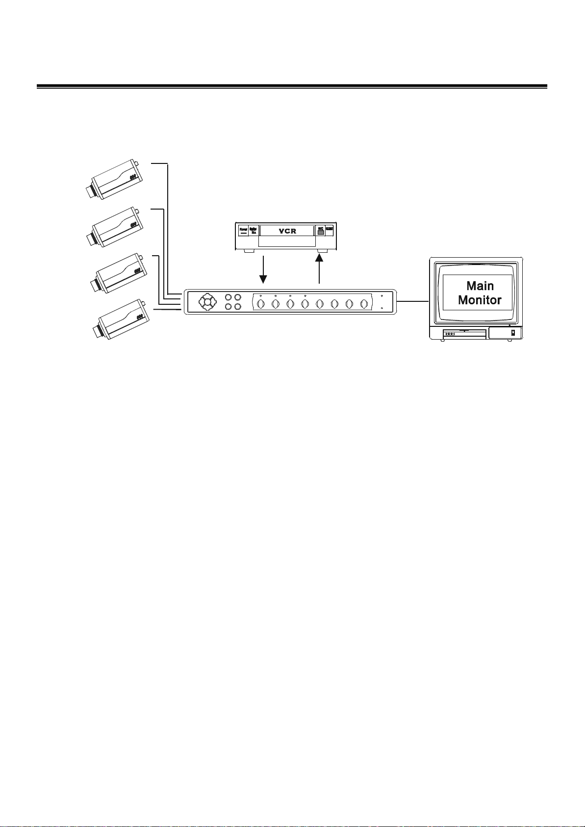
Systems Connection
4
The System Connection
of
4 Channel Color
Triplex Multiplexer
Page 7

5
Front Panel Definition
1~4 : Full channel display CH1~CH4 in live or playback mode on VCR
5 : Quad display in live or playback mode on VCR
6 : PIP display in live mode or 9 split display in playback mode
7 : 2x2 Zoom picture display in live or playback mode on VCR
8 : Freeze display in live mode
9 : Menu setup and Enter
10 : Select camera various display in Quad or PIP mode
11 : VCR playback mode
12 : Live display mode
13 : Up
14 : Right/Auto ( Sequence display in full ch mode or PIP mode )
15 : Down
16 : Left
Page 8

Rear Panel Definition
1~4 : Camera Input Port
5~8 : Camera Looping
9 : VCR S-VHS OUT (S-Video)
6
10 : VCR S-VHS IN (S-Video)
11 : VCR IN (BNC)
12 : VCR OUT (BNC)
13 : Main Monitor (BNC)
14 : Remote Control – RS232 Port (DB-9)
15 : Alarm Port (DB-9)
16 : 5V DC Power Input
17 : CH1~CH4 75 Ohm switcher
OFF - Looping out
ON - No Looping out
Page 9

7
Mode Function Description
Full screen display :
Press any channel CH1~CH4 , the picture of the corresponding
channel will fill the whole screen of the monitor. These function
keys are available in Live display and VCR playback mode .
Quad screen display
Either in live display or in VCR playback mode,
it is optional to set the video inputs as quad or
full screen. Press the Quad screen key, the
images of the four cameras will be displayed in
a quad page .
Use the SEL key to select which camera will be
displayed in the channel 1 and continues to set
which one of camera is in channel 2 channel 3
and channel 4 .
For example : press SEL then press 1213 , the
screen will be like
2
1
4
3
1
2
3
1
Note : You must select each channel in 8
seconds after pressed the SEL key, otherwise
the select function will be off automatically.
Auto sequential switching
Press Right/SEQ key the systems will enter the auto sequential
switching mode, the sequence of switching time is
programmable in setting menu. The camera inputs will be
sequentially displayed in full screen and PIP mode on the main
monitor according to the setting.
Zoom display function
Press Zoom key the systems will enter the 2x2 zoom mode no
matter in live or VCR playback display mode , the window of
zoom can be moved by keys UP/ Down/ Left /Right .
Page 10

PIP display mode : ( Picture in Picture )
Press PIP key the systems will enter the picture in picture mode ,
use the key 1~4 to select which channel will be displayed on the
main screen , press the SEL key and then key 1~4 to select which
channel will be displayed in the second window of the main
screen . We can switch cameras display sequentially on the
second window by pressing the key Right/Auto.
Main Screen
8
VCR playback mode
Press VCR key the systems will enter the VCR playback mode ,
Press any one of channels to display on Full Screen or press Quad
key for Quad Screen display or press Pip/All key for 9 split
display ( 4-ch live and 4-ch playback) and 2x2 Zoom function
could be available and moveable .
LD – Live Display
PD – Playback Display
LD
LD
LD
Second Window
Live Time Display
Playback Time Display
LD PD
PD PD
LD 00: 00: 00
PD 00: 00: 00
PD
Page 11

324
1
9
Pin Assignment
ALARM PORT ( DB-9 Female)
1~4 : Alarm Input CH1~CH4
5 : VCR Trigger
6 : GND
7 : Alarm Output NC
8 : Alarm Output COM
9 : Alarm Output NO
RS-232 PORT (DB-9 Female)
5 4 3 2 1
9 8 7 6
1 : Reserved
2 : RXD
3 : TXD
4 : Reserved
5 : GND
6 : Reserved
7 : Reserved
8 : Reserved
9 : Reserved
S-VHS PORT
1 : GND
2 : GND
3 : Y
4 : C
5 4 3 2 1
9 8 7 6
Page 12

Remote Control Command Definition
10
Key
1~4
5
6
7
8
9
10
11
RS232 remote control
ASCII CODE
‘A~D’
‘E’
‘F’
‘G’
‘H’
‘I’
‘J’
‘K’
12
13
14
15
16
‘L’
‘M’
‘N’
‘O’
‘P’
Page 13

11
Functional Setting
1. Menu Setup
Press the Menu key to set time/date, title on/off, camera titles, switching
dwell time, alarm polarity, alarm hold time, and time-lapse records.
There are 5 pages in the setting mode :
1: Date, time setting and on screen display on/off setting
2: Title setup
3: Alarm setup
4: Record setup
5: System setup
Keys for setting are as below:
Press key MENU to enter MENU SETUP mode
Press key UP/DOWN to select current setup item ( green words )
Press key RIGHT/LEFT to select setup data
Press key ENTER to enter other page or exit
Page 14

2. Date, Time, and On screen display setting
MENU
SET TIME Y00:M00:D00
H00:m00:s00
TIME DISPLAY ON OFF
TITLE DISPLAY ON OFF
ALARM FUNCTION ON OFF
TITLE SETUP PAGE ENTER
ALARM SETUP PAGE ENTER
RECORD SETUP ENTER
SYSTEM SETUP PAGE ENTER
EXIT ( NO SAVE ) ENTER
EXIT ( SAVE ) ENTER
DATE - data format is Y00-M00-D00, where
Y : Year data from 00 to 99
M : Month data from 01 to 12
D : Day data from 01 to 31
12
TIME - data format is H:m:s, where
H : Hour data from 00 to 23
M : Minute data from 00 to 59
S : Second data from 00 to 59
TIME DISPLAY ON/OFF
‘ON’ : Enable the Day & Time displayed on the screen
‘OFF’: Disable the Day & Time display function.
TITLE DISPLAY ON/OFF
‘ON’ : Enable the title of camera displayed on the screen
‘OFF’: Disable the display function.
ALARM FUNCTION ON/OFF
‘ON’ : Enable the alarm function
‘OFF’: Disable the alarm function
EXIT ( NO SAVE )
Exit setup menu and setup parameters will not to be saved .
EXIT ( SAVE )
Exit setup menu and setup parameters will be saved .
Page 15

3. Title Setup
13
TITLE SETUP
CAMERA CH TITLE
01 = CAM1
02 = CAM2
03 = CAM3
04 = CAM4
BACK TO MENU ENTER
Use the UP/ DOWN keys to select the channel and LEFT/ RIGHT keys to set the name
of camera and 4 characters title generator for each camera input .
Page 16

14
4. Alarm Setup
ALARM SETUP
ALARM DURATION 300 SEC.
ALARM BUZZER ON OFF
ALARM MARK DISPLAY ON OFF
ALARM CH POLARITY
01 = HIGH LOW OFF
02 = HIGH LOW OFF
03 = HIGH LOW OFF
04 = HIGH LOW OFF
BACK TO MENU ENTER
ALARM DURATION
Use the UP/ DOWN keys to select ALARM DURATION and LEFT/ RIGHT keys to
change data . ( 1 ~ 999 SEC )
ALARM BUZZER
Use the UP/ DOWN keys to select ALARM BUZZER and LEFT/ RIGHT keys to switch
the BUZZER ON/OFF .
ALARM MARK DISPLAY
Use the UP/ DOWN keys to select ALARM MARK DISPLAY and LEFT/ RIGHT keys to
switch the ALARM MARK display ON/OFF .
ALARM CH POLARITY
Use the UP/ DOWN keys to select ALARM CHANNEL CH1 ~ CH4 and LEFT/ RIGHT
keys to switch the ALARM channel polarity .
CH1 - CH4 :
‘LOW’ : Alarm is active low.
‘HIGH’ : Alarm is active high.
‘OFF’ : Alarm is not active no matter input signal is low or high .
Note: Alarm inputs can be a contact type or TTL/CMOS level signal
and connect another side to GND pin.
Page 17

5. Record Setup
15
RECORD SETUP
VCR RECORD TIME 012 H
VCR TRIG OFF
VCR INPUT TYPE BNC S-VIDEO
RECORD CH STATUS
01 = ON
02 = ON
03 = ON
04 = ON
BACK TO MENU ENTER
VCR RECORD TIME SETTING
Use the UP/ DOWN keys to select VCR RECORD TIME and LEFT/ RIGHT keys to
change the recording hour to be compatible with diverse VCR.
Real Time Setting : Set 002 H or below for real time recording
Time-Lapse Setting : Set the adjustable hour to match the Time-Lapse VCR .
For example : Set 024 H to match up 24 hours Time Lapse mode VCR and
increase or decrease the number from 22 H ~ 26 H to keep good
performance in record timing if 024H do not really match to VCR .
VCR TRIGGER SETTING ON/OFF
Use the UP/ DOWN keys to select VCR TRIGGER and LEFT/ RIGHT keys to set the
function enable or disable to record synchronously with VCR trigger .
VCR INPUT TYPE BNC / S-VIDEO
Use the UP/ DOWN keys to select VCR INPUT TYPE and LEFT/ RIGHT keys to switch
the input connecter between BNC and S-VIDEO types
RECORD CHANNEL SETTING ON/OFF
Use the UP/ DOWN keys to select RECORD CHANNEL CH1 ~ CH4 and LEFT/ RIGHT
keys to enable or disable the recording function for each channel .
Page 18

16
6. System Setup
SYSTEM SETUP
RS232 BAUD RATE 9600
SEQUENCE DWELL TIME 003 SEC
VIDEO TYPE NTSC PAL
SYSTEM DEFAULT ENTER
BACK TO MENU ENTER
BAUD RATE SETTING
Use the UP/ DOWN keys to select RS232 BAUD RATE and LEFT/ RIGHT keys to
change the baud rate from 1200 ~9600.
SEQUENCE DWELL TIME SETTING
Use the UP/ DOWN keys to select SEQUENCE DWELL TIME and LEFT/ RIGHT
keys to change the dwell time from 000 ~ 999 SEC for the auto sequence function .
VIDEO TYPE SETTING
Use the UP/ DOWN keys to select VIDEO TYPE and LEFT/ RIGHT keys to switch
the video signal format between NTSC and PAL .
SYSTEM DEFAULT SETTING
Use the UP/ DOWN keys to select SYSTEM DEFAULT and ENTER key to
make the system to be restored the default parameters before shipped .
Page 19

Page 20

Distributed By:
 Loading...