

Page 1
PVS-7
NIGHT VISION GOGGLES
OPERATION AND
MAINTENANCE MANUAL
Impor tant Export Res trictions ! Co mmodities, produ cts, technologi es and ser vices of thi s manu al are contro lled by the U.S.
Depar tment o f State Oce of De fense Trade Controls, in accordance with International Trac in Arms (ITAR), Title 22, Code of
Federal Regulati ons Part 120-130 and/or by the Expor t Administration Re gulations (EAR) of U.S. Depar tment of Commerce. At any
time whe n a license or a wri tten approval o f the U.S. Govern ment
is app licable to it, it i s illegal and stric tly forbidd en to exp ort, intend to export, tr ansfer in any other manner whatsoever, sel l any
hardwar e or technical da ta, provide any a ssociated ser vice to any
non-U. S. r esident, beyond or within the United States territory,
until th e valid lice nse or writ ten approval has been i ssued by the
Depar tments of th e U.S. Gover nment h aving j urisdiction . Addi tionall y U.S. law prohibits the sale, transfer, o r export of items to
certai n restri cted parties, des tinations, and embar goed countries,
as iden tied on lis ts maintaine d by the U.S . Departm ent of State,
the U.S. Department of Commerce, and t he U.S. Depar tment of
Treasury. It i s the responsib ility of the Customer to be aw are of
these lis ts. The sale, tran sfer, transport ation, or shipme nt outside of the U.S. of any product prohibited o r restricte d for expor t
without complying with U. S. export c ontrol laws and re gulations,
includin g prope r expor t licen sing, do cumentation or au thorization, is unlaw ful and may result in civil and/or cr iminal pen alties
and/or constitute a fe deral cri me. Diver sion cont rary to U.S. law
is stric tly prohibited .
Page 2

2
SAFETY SUMMARY
Before operating this product, carefully read and study this Operation and Maintenance Manual.
The PVS-7 is a precision electro-optical instrument, and requires careful handling. To avoid damage to
the equipment or physical harm to the user when operating the PVS-7, follow all WARNINGS, CAUTIONS
and NOTES.
Below you will nd denitions of the following alerts that appear throughout this Manual:
WARN ING — Identies a clear danger to the person operating the equipment.
CAUTION – Identies risk of damage to the equipment.
NOTE – Serves to highlight essential procedures, conditions, and statements, or convey important in-
structional data to the user.
WARNING:
This product contains natural rubber latex which may cause allergic reactions! The FDA
has reported an increase in the number of deaths that are associated with an apparent sensitivity to natural latex proteins. If you are allergic to latex, it is a good idea to learn which products
contain it and strictly avoid exposure to those products.
WARNINGS:
When used in total darkness, the light from the unit’s infrared (IR) illuminator is invisible to •
the unaided eye. However, the light can be detected by other Night Vision Devices (NVD).
To reduce the risk of detection by another NVD, avoid prolonged activation of the IR illumi-•
nat or.
The IR light is more easily detected by an NVD when used in smoke, fog and rain. Avoid pro -•
longed activation of the unit’s IR illuminator in these conditions.
The intensier’s phosphor screen contains toxic materials. Please note the following:•
If the intensier tube breaks, be extremely careful to avoid inhaling the phosphor screen —
material. DO NOT allow the material to come in contact with your mouth, eyes, or any
open wounds on the skin.
If the phosphor screen material comes in contact with your skin, wash it o immediately —
with soap and water.
If you inhale or swallow any phosphor screen material, drink a lot of water, induce vomit- —
ing, and seek medical attention as soon as possible.
The information provided in this manual is for familiarization purposes only; the contents may undergo further
changes with no commitment by Armasight© to notify Customers of any updates.
Armasight© assumes no responsibility for any misprints or other errors that this manual may contain.
©2012 by Armasight. Al l rights reserved.
Page 3

3
CAUTION:
The PVS-7 is a precision optical instrument. To prevent damage to the unit, it should always •
be handled carefully.
Do not scratch the external lens surfaces or touch them with your ngers.•
To protect the image intensier, keep the lens cap securely tted over the objective lens •
when the device is not in use, or when it is being used in daylight conditions.
The IR illuminator produces light that is invisible to a naked eye, so that it can be used in con-•
ditions of extreme darkness. However, the IR light can be detected by other NVDs.
Use of rubber eyecups for extended periods of time may cause skin inammation. If any •
symptoms develop, consult a doctor immediately.
NOTES:
Do not test the device in daylight conditions for more than ten (10) minutes, even with the •
daylight lter/ lens cap on.
To protect the device from damage, do not direct it at bright light sources (re, automobile •
headlights, lanterns, etc.).
The purpose of the built-in IR illuminator is to provide additional illumination when neces-•
sary while viewing scenes at close distances (up to 3 meters).
The unit is equipped with an Automatic Shut-o System. When the goggles are removed •
from the head mount or helmet mount while turned on, they will turn o automatically. To
turn the unit on after automatic shut o, you will need to rotate the operation knob to the
OFF position rst and then return it to the ON position.
To avoid physical danger to the user and damage to the equipment, carefully read and un-•
derstand the following equipment limitations:
The equipment requires some ambient light (moonlight, starlight, etc.) to operate. —
Performance of the device in nighttime conditions depends on the level of ambient light —
in the environment. Please remember the following:
The level of ambient light is reduced by the presence of clouds, shade, or objects that •
block natural light (trees, buildings, etc.).
The equipment is less eective when operated in shadows and other darkened areas.•
The equipment is less eective when operated in rain, fog, sleet, snow, dust or smoke.•
The equipment will not “see” through dense smoke.•
Page 4

4
LIST OF CONTENTS
TITLE PAGE
Safety Summary 2
List of Contents 4
How to Use This Manual 6
1. INTRODUCTION 7
1.1 General Information 7
1.1.1 Type of Manual 7
1.1.2 Model Number and Equipment Name 7
1.1.3 Purpose of Equipment 7
1.1.4 Reporting Equipment Improvement Recommendations 7
1.2 Warranty Information and Registration 8
1.2.1 Warranty Information 8
1.2.2 Limitation of Liability 8
1.2.3 Product Warranty Registration 8
1.2.4 Obtaining Warranty Service 9
1.3 Cross References 9
1.4 List of Abbreviations 10
2. DESCRIPTION AND DATA 11
2.1 System Description 11
2.2 Specications 13
2.3 Operation principles 14
2.3.1 Mechanical Functions 14
2.3.2 Optical and Electrical Functions 15
3. OPERATING INSTRUCTIONS 16
3.1 Operating Procedures 16
3.1.1 General 16
2.1.2 Controls and Indicators 16
3.2 Preventive Maintenance Checks and Services (PMCS) 18
3.2.1 Purpose of PMCS 18
3.2.2 Frequency of Performing PMCS 18
3.2.3 Performance of PMCS 18
3.3 Assembly and Preparation 20
3.3.1 Preparation of Use 20
3.3.2 Installation of the Quick Disconnect Helmet Mount Assembly 26
3.3.3 Operating Procedures 27
3.3.4 Preparation for Storage 32
4. MAINTENANCE INSTRUCTIONS 33
4.1 Troubleshooting Procedures 33
4.1.1 Troubleshooting 33
4.2 Identication of Operational Defects 34
4.2.1 Operational defects 34
4.2.2 Cosmetic Blemishes 35
Page 5

5
4.3 Maintenance 36
4.3.1 General 36
4.3.2 Head Mount Maintenance 37
4.4 Service/Packing and Unpacking 37
4.4.1 Return Instructions 37
APPENDIX 38
A. PVS-7 List of Spare Parts 38
B. Product Warranty Registration Card 41
Alphabetical Index 43
LIST OF FIGURES
FIGURE TITLE PAGE
2-1 PVS-7 Components 12
2-2 Mechanical Controls for PVS-7 14
3-1 PVS-7 Controls 16
3-2 Battery and Eye cap Installation 21
3-3 Installation of Demist Shields, Sacricial Window 22
3-4 Installation of Compass 23
3-5 Installation of the IR Spot/Flood Lens 23
3-6 PVS-7 Head Mount Adjustments 24
3-7 Helmet Mount Features 25
3-8 Neck Strap Installation 26
3-9 Quick Disconnect Helmet Mount Features 26
3-10 Flip-up Helmet Mount 29
3-11 View Through Installed Compass 30
3-12 PVS-7 with Magnier Lens Assembly Installed 31
3-13 PVS-7 Shipping/storage case 32
4-1 Shading 35
4-2 Edge Glow 35
4-3 Emission Points and Bright Spots 36
4-4 Fixed-Pattern Noise 36
4-5 Chicken Wire 36
4-6 Re-installing the Neck Pad 37
4-7 Lacing the Sliding Bar Buckles 38
Page 6

LIST OF TABLES
TABLE TITLE PAGE
2-1 PVS-7 System Description 12
2-2 PVS-7 Optional Equipment 12
2-3 Operator Adjustment Limits 13
2-4 Electrical Data 13
2-5 Mechanical Data 13
2-6 Optical Data 13
2-7 Environmental Data 14
2-8 Consumable Items 15
3-1 Controls and Indicators 17
3-2 Preventive Maintenance Checks and Services 18
3-3 Estimated Battery Life 21
4-1 Operator’s Troubleshooting 33
A-1 PVS-7 List of Spare Parts 39
HOW TO USE THIS MANUAL
USAGE
You must familiarize yourself with the entire manual before operating the equipment. Before performing any kind of maintenance on your device, read the section on maintenance in its entirety. Follow all
WARNINGS, CAUTIONS, and NOTES.
MANUAL OVERVIEW
This manual contains sections on Operating and Maintaining the PVS-7 Night Vision Goggles.
The list of Spare Parts can be found in Appendix A.
The Product Warranty Registration Card can be found in Appendix B.
6
Page 7

7
1
INTRODUCTION
1.1 GENERAL INFORMATION
1.1.1 TYPE OF MANUAL
Operation and Maintenance.
1.1.2 MODEL NUMBER AND EQUIPMENT NAME
PVS-7 Night Vision Goggles
1.1.3 PURPOSE OF EQUIPMENT
To provide the operator with the ability to observe scenes at night, under moonlight and starlight conditions.
The PVS-7 can be used as a handheld, head-mounted or helmet-mounted device. When mounted to
the head or a helmet, the user will be able to easily operate the device while walking, performing shortrange surveillance, reading maps, performing vehicle maintenance, or administering rst aid.
The PVS-7 allows for horizontal and vertical adjustments when mounted to the user’s head or helmet,
and is equipped with an infrared light-emitting source (IR illuminator).
1.1.4 REPORTING EQUIPMENT IMPROVEMENT RECOMMENDATIONS
Armasight encourages user recommendations for improvements to the device.
Mail your comments to:
Armasight Inc.
815 Dubuque Avenue
South San Francisco, CA 94080
USA.
Or, you can send an email to info@armasight.com.
Page 8

8
1.2 WARRANTY INFORMATION AND REGISTRATION
1.2.1 WARRANTY INFORMATION
This product is guaranteed to be free from manufacturing defects in material and workmanship under
normal use for a period of two (2) years from the date of purchase. In the event that a defect covered
by the below warranty occurs during the applicable period stated above, Armasight, at its discretion,
will either repair or replace the product; such action on the part of Armasight shall be the full extent of
Armasight’s liability, and the Customer’s sole and exclusive reparation. This warranty does not cover a
product if it has (a) been used in ways other than its normal and customary manner; (b) subjected to
misuse; (c) subjected to alterations, modications or repairs by the Customer of by any party other than
Armasight without prior written consent of Armasight; (d) special order or “close-out” merchandise
or merchandise sold “as-is” by either Armasight or the Armasight dealer; or (e) merchandise that has
been discontinued by the manufacturer and either parts or replacement units are not available due to
reasons beyond the control of Armasight. Armasight shall not be responsible for any defects or damage that in Armasight’s view are a result from the mishandling, abuse, misuse, improper storage or
improper operation of the device, including use in conjunction with equipment that is electrically or
mechanically incompatible with, or of inferior quality to, the product, as well as failure to maintain the
environmental conditions specied by the manufacturer. CUSTOMER IS HEREBY NOTIFIED THAT OPERATION OF THE EQUIPMENT DURING DAYLIGHT HOURS OR UNDER ANY EXCESSIVE LIGHT CONDITIONS
MAY PERMANENTLY DAMAGE THE INTERNAL COMPONENTS OF THE UNIT AND SAID DAMAGE WILL
NOT BE COVERED UNDER THIS WARRANTY. This warranty is extended only to the original purchaser.
Any breach of this warranty shall be enforced unless the Customer noties Armasight at the address
noted below within the applicable warranty period.
The Customer understands and agrees that except for the foregoing warranty, no other warranties
written or oral, statutory, expressed or implied, including any implied warranty of merchantability or
tness for a particular purpose, shall apply to the product. All such implied warranties are hereby and
expressly disclaimed.
1.2.2 LIMITATION OF LIABILITY
Armasight will not be liable for any claims, actions, suits, proceedings, costs, expenses, damages or
liabilities arising out of the use of this product. Operation and use of the product are the sole responsibility of the Customer. Armasight’s sole undertaking is limited to providing the products and services
outlined herein in accordance with the terms and conditions of this Agreement. The provision of products sold and services performed by Armasight to the Customer shall not be interpreted, construed,
or regarded, either expressly or implied, as being for the benet of or creating any obligation toward
any third party of legal entity outside Armasight and the Customer; Armasight’s obligations under this
Agreement extend solely to the Customer. Armasight’s liability hereunder for damages, regardless of
the form or action, shall not exceed the fees or other charges paid to Armasight by the Customer or
Customer’s dealer. Armasight shall not, in any event, be liable for special, indirect, incidental, or consequential damages, including, but not limited to, lost income, lost revenue, or lost prot, whether such
damages were foreseeable or not at the time of purchase, and whether or not such damages arise
out of a breach of warranty, a breach of agreement, negligence, strict liability or any other theory of
liability.
1.2.3 PRODUCT WARRANTY REGISTRATION
In order to validate the warranty on your product, Armasight must receive a completed Product Warranty Registration Card for each unit, or the Customer can complete a warranty registration form on
our website at www.armasight.com. Please complete the included form (Appendix C) and immediately
mail it to our Service Center:
Armasight Inc.
815 Dubuque Avenue
South San Francisco, CA 94080
USA
Page 9

9
1.2.4 OBTAINING WARRANTY SERVICE
To obtain warranty service on your unit, the End-user (Customer) must notify the Armasight service
department via email. Send any requests to service@armasight.com to receive a Return Merchandise
Authorization number (RMA). When returning any device, please take in the product to your retailer, or
send the product, postage paid and with a copy of your sales receipt, to Armasight Corporation’s service center at the address listed above. All merchandise must be fully insured with the correct postage;
Armasight will not be responsible for improper postage or merchandise that becomes lost or damaged
during shipment. When sending product back, please clearly write the RMA# on the outside of the
shipping box. Please include a letter that indicates your RMA#, the Customer’s Name, a Return Address,
reason for the return, Contact information (valid telephone numbers and/or an e-mail address), and
proof of purchase that will help us to establish the valid start date of the warranty. Product merchandise returns that do not have an RMA# listed may be refused, or a signicant delay in processing may
occur. Estimated Warranty service time is 10-20 business days. The End-user/ Customer is responsible
for postage to Armasight for warranty service. Armasight will cover return postage/ shipping after warranty repair to the End-user/ Customer only if the product is covered by the aforementioned warranty.
Armasight will return the product af ter warranty service by domestic UPS Ground service and/ or domestic mail. Should any other requested, required or international shipping methods be necessary, the
postage/ shipping fee will be the responsibility of the End-user/ Customer.
1.3 CROSS REFERENCES
COMMON NAME OFFICIAL NAME
Allen Wrench Socket Head Screw Key
Battery Compartment Battery Box Cover
Shipping Case Textile Bag
Cotton Swab Disposable Applicator
Neoprene Jack Plug Plug Assembly
O-Ring Gasket
Safety Screw Electrical Dial-Knob Lock
Pattern Generator Optical Instrument Reticle
Lens Covers Exit Port Covers
Paddle Switch Remote Cable Switch
Batteries AA
Technical Manual Operator and Field Maintenance Manual
Tape Fastener Loop Fastener, Loop Tape
Tape Fastener Hook Fastener, Hook Tape
Page 10

1.4 LIST OF ABBREVIATIONS
C Celsius (Centigrade)
CCW counterclockwise
Cont’d Continued
CW clockwise
Dia diameter
F Fahrenheit
FOV Field of View
g gram
Gen Generation
H Height
hr hour
IR infrared
IT Intensier Tube
L Length
LED Light Emitting Diode
lx lux
m meter
mA milliampere
min minute
mm millimeter
mW milliwatt
nm nanometer
No Number
NV Night Vision
NVD Night Vision Device
Para Paragraph
PMCS Preventive Maintenance Checks and Services
QRM Quick Release Mount
QTY Quantity
RMA# Return Merchandise Authorization number
s second
seq sequence
SR Service Representative
VDC Volts Direct Current
V Volt
W Width
10
Page 11

11
2
DESCRIPTION AND DATA
2.1 SYSTEM DESCRIPTION
The PVS-7 is a hand-held, head-mounted or helmet-mounted night vision system that enables mobility, driving, weapon ring, short-range surveillance, map reading, vehicle maintenance and administering rst aid during operation in both moonlight and starlight. Each unit allows for vertical adjustment
(using the head straps), fore-and-aft adjustment, objective lens focus, eyepiece focus and eye relief
distance adjustment. The goggles are also equipped with an infrared (IR) light-emitting diode (or illuminator) and a low battery LED indicator. The goggles automatically shut o when disconnected
from the head mount or helmet mount, or when ipped up on the helmet mount. A bright light cuto
feature shuts o power to the goggles when they are exposed to excessive levels of light for more than
70 (±30) seconds.
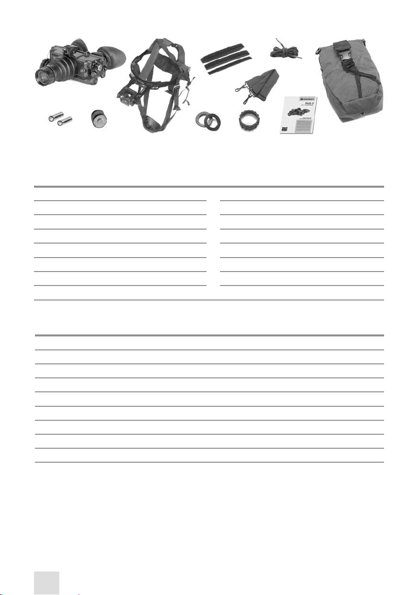
The PVS-7 includes the items shown in Figure 2-1. See Table 2-1, Table 2-2 and Figure 2-1 for Standard
and Optional Equipment.
A. Goggles Assembly. The goggles assembly consists of four primary sub-assemblies; a simple objective lens, a wired housing assembly, an image intensier tube (IIT) assembly (not shown), and a rear
cover assembly. The wired housing assembly contains a built-in battery compartment, attached battery cap and the RESET/ OFF-ON-IR/ PULL switch.
B. Head mount Assembly. The adjustable, cushioned head mount assembly secures the goggles
to the operator’s head, providing hands-free operation and allowing the use of weapons, protective
masks and other devices. The thin brow pad (intended for use with larger heads) comes attached to
the head mount. Thicker, or medium, brow pads (intended for use with smaller heads) are stored in the
carrying case.
C. Carrying Case. The canvas carrying case is provided for transportation and protection of the PVS-7,
head mount assembly, batteries and accessories. Two slide keepers are provided for belt attachment.
A carrying case strap, which can be attached to the two D-rings on the back of the carrying case, is also
included. The case has a zipper closure.
D. Demist Shields. The two demist shields are used to prevent the eyepiece lenses from becoming
fogged.
E. Sacricial Window. A replaceable sacricial window is supplied to protect the objective lens during
operation in adverse conditions.
F. Neck Cord. This additional authorized item can be attached to the compass or 3X magnier lens and
worn by the operator to prevent them from dropping or losing these items.
I. Optional Equipment. Optional equipment includes compass, helmet mount assembly, 3x and 5x
Mil-Spec Magnier Lenses, Long Range Infrared illuminator, Mil-Standard Hard Shipping/Storage Case
and an IR spot/ ood lens.
The PVS-7 may sometimes be supplied in hard shipping and storage case. Batteries may also be stored
in this case.
Page 12
12
5
6
7
8
1
4
2
3*
10
11
9
12
FIGURE 21. PVS7 COMPONENTS
TABLE 21. PVS7 SYSTEM DESCRIPTION
ITEM DESCRIPTION ITEM DESCRIPTION
1 PVS-7 Assembly 8 Neck Cord
2 AA Alkaline Batteries 9 Shoulder Strap Assembly
3* Image intensier Tube 10 Demist Shield Assembly
4 Large Brow Pad Head mount Assembly 11 Sacricial Window
5 Large Brow Pad 12 Operator’s Manual
6 Medium Brow Pad 13 Carrying Case
7 Thin Brow Pad 14 Lens Paper (Not Shown)
* Equipment with variants.
TABLE 22. PVS7 OPTIONAL EQUIPMENT
ITEM DESCRIPTION PART NO.
1 MICH Helmet Mount Assembly USA #107 ANHM000005
2 PASGT Helmet Mount Assembly USA #108 ANHM000006
3 3x Mil-Spec Magnier Lens #99 ANAF3X0003
4 5x Mil-Spec Magnier Lens #100 ANAF5X0001
5 Magnetic Compass #110 ANKI000009
6 IR850 Detachable Long Range Infrared illuminator #76 IAIR850IR000001
7 SKB Mil-Standard Hard Shipping/Storage Case (F100) ANHC000001
8 IR Spot/Flood Lens
13
Page 13

13
2.2 SPECIFICATIONS
The following tables provide information pertaining to the operational, electrical, mechanical, optical
and environmental characteristics for the goggles.
TABLE 23. OPERATOR ADJUSTMENT LIMITS
ITEM LIMITS
Interpupillar y Distance 55 to 71mm
Diopter Focus +2 to -6 diopters
Objective Focus 25cm to innity
TABLE 24. ELECTRICAL DATA
ITEM DATA
Power Source Battery (3 VDC max.)
Battery Requirements 2 AA Alkaline or 1 Lithium (BA-5567/U)
TABLE 25. MECHANICAL DATA
ITEM DATA
Shipping and Storage Case Size: Approx. 17”x12”x7”
Weight: 6.7 lbs.
Soft Carrying Case Size: Approx. 14”x8”
Goggles * Size: 6.4”x6”x3”
Weight 1.5 lbs
* The weight of the PVS-7 does not include accessories.
TABLE 26. OPTICAL DATA
ITEM DATA
Magnication 1.0X
Field of View 40
o
Eyepiece Focus +2 to -6 diopters
Focus Range 25cm (9.8”) to innity
TABLE 27. ENVIRONMENTAL DATA
ITEM DATA
Operating Temperature -40oC to +50oC
Storage Temperature -50oC to +70oC
Illumination Required Overcast starlight to moonlight
Waterproof 1 meter for 30 min.
Page 14
14
2.3 OPERATION PRINCIPLES
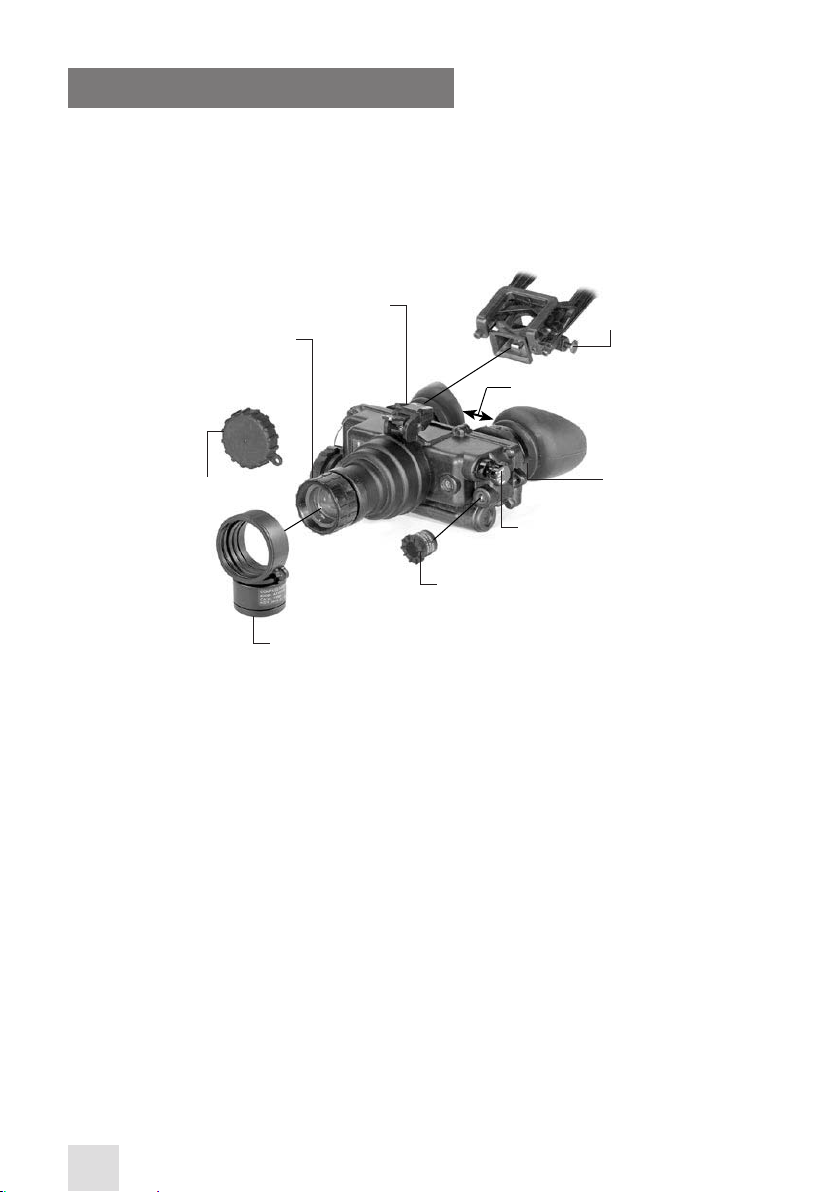
2.3.1 MECHANICAL FUNCTIONS
Mechanical adjustments of the PVS-7 allow for physical dierences between individual operators using the system. The goggles’ functions include the power switch, interpupillary adjustment, release
latch, eye relief adjustment, diopter adjustment, IR spot/ ood focus (optional), compass illumination
(optional), and objective lens focus. The mechanical controls are identied in Figure 2-2.
lenS cap
objec tIve
lenS focuS
Knob
compaSS
IllumInatIon
butto n
(underneath)
lat ch
Interp upIllary adj.
reSet/off-on-Ir/
pull SwIt h Knob
Ir Spot/flood f ocuS Knob
eye
relIef
dIopt er
adj. rIng
FIGURE 22. MECHANICAL CONTROLS FOR PVS7
2.1.2 OPTICAL AND ELECTRICAL FUNCTIONS
The optical functions include an objective lens, image intensier, a collimator lens, and two eyepieces.
The objective lens collects light reected from the moon, stars or other ambient light in the night
sky, and inverts and focuses an image of the scene onto the image intensier. The electrical functions
include the following:
A. Power Source. The electronic circuit is powered by replaceable batteries - either a 3.0 Volt lithium
battery (BA-5567/U) or two AA 1.5 Volt alkaline batteries (BA-3O5S/U).
B. Electrical Principles. Power from the batteries is supplied to the components through the RESET/
OFF-ON-IR/ PULL switch as follows:
RESET/ OFF Position. With the switch in the OFF position, the circuit will not supply energy to the image
intensier or the IR illuminator. You can also turn the switch to this position to reset your device after
automatic shuto or bright light cuto.
ON Position. Energy is drawn from the battery compartment to power the goggles. When the voltage
drops to 2.4 VDC, a low battery indicator will begin to blink on the right side region of the eyepiece,
indicating approximately 30 minutes of remaining operating time.
IR/ PULL Position. Energy is drawn from the battery compartment to power the goggles and IR light
source, and a steady red indicator light will appear in the left side region of the eyepiece. The IR can be
momentarily turned on by turning the switch ON without pulling the knob.
Page 15

15
C. Automatic Shuto. When the goggles are removed from the head mount or helmet mount while
in on and in use, they will automatically shut o. This prevents detection by other NVDs by eliminating
the green glow of the image intensier. To turn the goggles back on, ip the switch to RESET/ OFF and
then back to ON again.
D. High Light Cuto. The goggles will automatically shut o after 70 (±30) seconds of operation in
daylight or bright room light. Individual bright lights (headlights, ashlights or other concentrated
light sources) will not activate the high light cuto function, unless the light is focused directly onto
the high light detector located on the front of the goggles. To turn the goggles back on, ip the switch
to RESET/ OFF and then back to ON again.
2.1.3 CONSUMABLE ITEMS
Items listed in Table 2-8 are recommended for operator maintenance.
TABLE 28. CONSUMABLE ITEMS
ITEM LIMITS
Lens Paper -
Color Swabs -
Alcohol -
Page 16
16
3
OPERATING INSTRUCTIONS
3.1 OPERATING PROCEDURES
3.1.1 GENERAL
This section contains instructions for operating the PVS-7 under normal conditions. Explanations of
control functions and indicators are provided.
CAUTION:
The PVS-7 is a precision electro-optical instrument and must be handled carefully at all times.
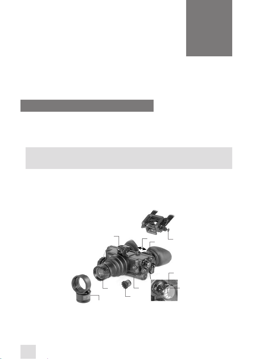
3.1.2 CONTROLS AND INDICATORS
The PVS-7 is adjustable to accommodate dierent users and corrects for most dierences in eyesight.
The controls and indicators for the PVS-7 are shown or described in Figure 3-1 and Table 3-1.
7
5
4
FIGURE 31. PVS7 CONTROLS
12
6
3
10
11
1
2
Page 17

TABLE 31.CONTROLS AND INDICATORS
ITEM CONTROLS AND
INDICATORS
FUNCTIONS
Controls goggles and IR light power. ON or OFF.
RESET/ OFF: Same as system OFF. Also resets goggles after auto-
1 RESET/OFF-ON-IR/PULL
matic shut-o or high light cuto.
ON: Goggles activated.
IR/PULL: Pull switch out and turn clockwise to activate goggles
and IR. Illuminates LED indicator in left eyepiece.
NOTES:
Some PVS-7’s contain an additional momentary IR function. For momentar y IR, continue to turn the
switch knob clockwise, past ON and without pulling. The switch will return to the ON position when
released.
RESET/OFF-ON-IR/PULL
2
Label
3 IR Spot/Flood Lens
Denes the switch positions.
Focuses the IR light for a narrow beam (spot) or wide angel
(ood) beam illumination.
Pressing this button activates the compass illuminator LED, which
4 Compass Illuminator Button
makes compass readings visible in the goggles’ viewing area.
Additional pressure will make the image brighter. The image will
disappear when the button is released.
5 Objective Focus
6 Battery Polarity Indicator
7 Latch
LED On Indicator (Not
8
Show n)
Low Battery Indicator (Not
9
Show n)
10 Diopter Adjustment Ring
Focuses objective lens. Adjusts for sharpest image of viewed
object.
This feature is molded into the PVS-7 and shows the proper orientation of the batteries.
The latch is used to separate the goggles’ assembly from the
head mount/ helmet mount ’s assembly.
When illuminated (left eyepiece), this light indicates that the IR
illumination is on.
When illuminated (right eyepiece), this light indicates a low battery condition with less than 30 minutes of batter y life remaining.
Focuses eyepiece lens for each eye without the need for glasses.
Adjusts for sharper image on intensier screen.
Adjusts the distance between each eyepiece by sliding them
11 Interpupillary Adjustment
together or apart, allowing for each eye to observe the entire
eld at the same time.
12 Eye Relief Adjusts the distance between your eyes and the goggles.
17
Page 18

18
3.2 PREVENTIVE MAINTENANCE CHECKS AND SERVICES PMCS
3.2.1 PURPOSE OF PMCS
PMCS should be performed daily when the PVS-7 is in use in order to ensure that the sight is missionready at all times. Procedures are a systematic inspection of the goggles that will enable you to discover
defects that could cause the PVS-7 to fail on a mission.
3.2.2 FREQUENCY OF PERFORMING PMCS
You should perform PMCS as follows:
A. Daily when the PVS-7 is in use.
B. Weekly when in standby condition.
C. Semi-annually when stored in depot or administrative storage.
3.2.3 PERFORMANCE OF PMCS
Preventive maintenance checks and ser vices should be performed in the sequence and inspection
procedures indicated in Table 3-2.
TABLE 32. PREVENTIVE MAINTENANCE CHECKS AND SERVICES
SEQUENCE
NO.
1
2
3
4
5
6
7
8
9
10
11
ITEM TO BE I NSPECTED/
PROCEDURE
GOGGLES - Check for completeness, including accessories. Check for dirt and moisture on
external surfaces and parts. Clean and dry with a lint-free cloth.
SHIPPING CASE - Check for dirt, moisture and mildew. Clean with a mild detergent and
water. Dry with a lint-free cloth.
CARRYING CASE - Check for dirt, moisture and mildew. Clean with a mild detergent and
water. Dry with a lint-free cloth.
BATTERIES - Remove batteries. Check for corrosion on terminals and dirt or moisture in
the battery cap. Clean battery cap with a dry cloth. Replace the batteries if corroded.
LENSES - Check for dirt and moisture. Clean with lens paper or a brush and/ or alcohol and
cotton swabs.
EYECUPS - Check for dirt, dust, cracked or torn cups. Inspect for bent, broken or improperly tting eyecups.
INTERPUPILLARY ADJUSTMENT - Slide each eyepiece back and forth to check for binding
or looseness.
OBJECTIVE LENS FOCUS KNOB - Rotate objective lens focus knob to ensure free movement (range is approximately 1/3 turn).
NECK CORD & LENS CAP- Check for cracked, torn or missing lens cap. Inspect cord for cuts,
damage or frayed ends. Re-tie ends if necessary.
LATCH - Inspect for damage.
RESET/ OFF-ON-IR/ PULL SWITCH - Remove any batteries and turn the switch from RESET/
OFF to ON or IR/ PULL. Each position should have a denite stopping point. Inspect for
broken or missing knob.
Page 19

19
TABLE 32. CONT INUED
SEQUENCE
NO.
ITEM TO BE I NSPECTED/
PROCEDURE
HEAD MOUNT
STRAPS AND PADS - Check for cuts tears, fraying, holes, cracks or defective fasteners.
12
SOCKET - Check for dirt, dust or corrosion. Insert the goggles’ latch into the socket to
verify the secure attachment of the goggles to the head mount. If necessary, clean the
13
socket with water.
FORE-AND-AFT ADJUSTMENT - Press the socket-release button and check for free motion.
14
Inspect for damage.
OPTIONAL HELMET MOUNT
STRAPS - Inspect for cuts, tears, fraying, holes, cracks or defective fasteners
15
SOCKET - Check for dirt, dust or corrosion. Insert goggles latch into socket to verify secure
16
attachment of goggles helmet mount. If necessary, clean socket with water.
FORE-AND-AFT ADJUSTMENT - Press the socket-release button and check for free motion.
17
Inspect for damage.
FLIP-UP/ AUTO OFF - With the goggles on, ip them up and verify the operation of the
18
auto-o function.
TILT ADJUSTMENT - Verify that the knob locks tilt while in place, and that the full range of
19
the tilt is reached when the knob is loosened.
SOFT CARRYING CASE - Remove all items and shake out loose dirt or foreign material.
20
Inspect for tears, cuts, excess wear or damage to mounting clips.
SHOULDER STRAP ASSEMBLY - Inspect for cuts, tears or excess wear of clips.
21
NOTES:
Damaged optional items (compass, IR spot/ ood, sacricial window, demist shields) do not make the
assembled unit to be “not fully mission capable.” However, the damaged item should be replaced as
soon as practical to restore full capability of the system.
ACCESSORY ITEMS
DEMIST SHIELDS - Inspect for dirt, dust, scratches or damage. If necessary, clean when the
22
shields are dry and with dry lens paper only.
IR SPOT/ FLOOD LENS - Rotate IR focus lens to ensure free movement.
23
COMPASS ASSEMBLY - Inspect for dirt, dust, scratches or damage. If necessary, clean with
water and dry with lens paper. Install the compass assembly and turn the goggles on.
24
When the illumination button is depressed, the compass should be visible.
3X/5X AFOCAL MAGNIFIER LENS - Check lens for scratches or damage. Check mating to
25
objective lens by screwing it in or pressing it on with the adapter installed.
Page 20

20
3.3 ASSEMBLY AND PREPARATION
3.3.1 PREPARATION FOR USE
This chapter contains information necessary to prepare the goggles for operation. This includes unpacking, examination for damage, battery installation, sacricial window installation, and head mount
installation and adjustments.
A. Unpacking. The following steps must be accomplished prior to each mission.
CAUTION:
Before releasing the latches on the carrying case, relieve air pressure from inside the shipping
and storage case by pressing the relief valve button located near the handle of the carrying
case.
1. Release the two latches securing the top of shipping and storage case, and open the top.
2. Check the contents of the shipping and storage case for completeness (see Figure 1-1).
3. Remove the carr ying case from the shipping and storage case. Open the carrying case (Figure 1-1),
remove the PVS-7 and check contents for completeness.
4. Inspect the goggles for obvious evidence of damage to optical surfaces, body, eyecups, RESET/ OFFON-IR /PULL switch, battery cap, etc. Ensure that all optical surfaces are clean and ready for use. If
necessary, clean with lens paper.
B. Installation of Batteries.
CAUTION:
To protect the image intensier, keep the lens cap securely tted over the objective lens when
the goggles are not in use or when performing daylight checks.
NOTE:
Operation of the PVS-7 in daylight conditions will activate the high light cut o after 70 (±30)
seconds, causing the goggles to shut down.
WARNING:
The lithium battery contains sulfur dioxide gas under pressure.
Do not heat, puncture, disassemble, short circuit, attempt to recharge or otherwise tamper
with the batteries.
Turn o the equipment if the battery compartment becomes excessively hot. If possible, wait
until the batteries have cooled before removing them.
These types of batteries have safety vents to prevent explosion. When they are venting gas,
they release a very potent smell, and you may hear the sound of gas escaping. When the safety
vents have worked correctly, the batteries will be fairly safe from bursting, but because of excessive heat still must be handled with extreme care.
If you inhale sulfur dioxide, seek medical attention immediately.
The PVS-7 will operate with either of the two battery types identied in Table 2-3. Batteries are not supplied with the PVS-7 and must be purchased by the user.
Page 21

21
TABLE 33. ESTIMATED BATTERY LIFE
BATTERY TYPE NEGLIG IBLE IR USAGE IR USAGE 10% OF THE TIME
Lithium (BA-5567/U) 47-85 Hours 36-65 Hours
AA Alkaline (BA-3058/U) 89-160 Hours 68-123 Hours
NOTE:
The batter y data in Table 2-4 represents operation at room temperature. When operating in
cooler conditions, batter y life will decrease.
CAUTION:
Always verify that the Reset/ o-on IR/ pull switch is in the o position before installing batteries.
Install either two (2) AA batteries or one (1) BA-5567/ U lithium battery as follows. Do not attempt to mix
battery types in the compartment.
1. Remove the battery cap by turning it counterclockwise.
2. Verify that the o-ring is present. If not, replace it.
3. Observe the polarity markings on the outside of the battery compartment and insert either two AA,
1.5 Volt batteries or one 3.0 Volt BA-5567/U lithium battery into the battery compartment, plus (+)
end rst. (See Figure 3-2)
4. Secure the battery cap back on by placing it over the compartment and turning it clockwise. Verify
that it is rmly tightened to ensure a watertight seal.
C. Installation of the Eyecups. Perform the following procedure to install the eyecups onto the PVS-7.
Refer to Figure 3-2.
1. Carefully press each eyecup over the diopter cell retainer.
2. Rotate each eyecup into the proper viewing position. Adjust for the best t. The eyecups must seal
around your eyes and prevent the light from the green glow from escaping.
alKalIne
bat ter Ie S
(SIze aa)
lIthIum
bat ter y eyecup
battery cup
wIth o- rIng
FIGURE 32. BATTERY AND EYE CAP INSTALLATION
D. Installation of the Demist Shields. Perform the following procedure to install the demist shields
on the diopter lenses. Refer to Figure 3-3.
Page 22

22
CAUTION:
If the demisting shields need to be cleaned, make sure the shields are dry and only use dry lens
paper. If the demist shields are wiped while wet or with wet lens paper, you will damage the
coating.
NOTE:
If inclement operating conditions are known to be a possibility prior to your mission (e.g. signicant temperature change and high humidity), install the demist shields before operation in
order to minimize diopter lens fog.
1. Carefully remove the eyecups.
2. Carefully press a demist shield onto each eyepiece. Be careful not to smudge the eyepieces or demist
shields.
3. Replace the eyecups (see paragraph 3.3.
demISt
ShIeldS
compaSS
Ir Spot/flood l enS
SacrIfIcIal
wIndow
FIGURE 33. INSTALLATION OF DEMIST SHIELDS, SACRIFICIAL WINDOW
E. Installation of the sacricial Window. Perform the following procedure to install the sacricial
window. Refer to Figure 3-3.
CAUTION:
If adverse operating conditions (dust or sand), are known to exist, attach the sacricial window
to protect the objective lens from scratches or other damage.
1. If the compass assembly or lens cap is in place, remove it.
2. Carefully push the sacricial window over the objective lens until it stops. Turn the sacricial window
clockwise until it snaps into place.
F. Installation of the Compass Assembly.
NOTES:
a. Prepare the PVS-7 for operation (paragraph 3.3.1).
b. Ensure the neck cord is secured to the compass and clothing before installing.
1. If the sacricial window or lens cap is in place, remove it.
2. Turn the PVS-7 on.
Page 23

23
3. While looking through the goggles, rotate the objective lens focus completely counterclockwise.
4. Press the compass assembly onto the objective lens at an angle using your left hand. Slowly turn the
compass assembly counterclockwise until it is in the vertical position (with the compass illumination
button pointing down). See Figure 3- 4.
5. Ensure that the compass ts tightly to the PVS-7.
NOTE:
The o-ring must be in place in the compass assembly in order for the compass to t properly.
6. Refer to paragraph 3.3.3, D for operation of the compass.
FIGURE 34. INSTALLATION OF COMPASS
G. Installation of the IR Spot/Flood Lens.
1. Press the IR spot/ ood lens over the IR source until it is tight against the goggles. Refer to Figure
3-5.
FIGURE 35. INSTALLATION OF THE IR SPOT/FLOOD LENS
H. Installation and Adjustment of the Head Mount Assembly. Perform the following procedures for
putting the head mount on.
NOTE:
Do not put the head mount on while the PVS-7 is attached to it.
1. Prior to putting on the head mount, loosen the four chin straps so the ends of each strap are approximately two inches from the sliding bar buckles (See Figure 3-6)
2. Snap the front and rear snaps into place.
NOTE:
If the head mount is too loose, remove the attached thin brow pad and replace with either the
medium or large brow pad (both are stored in the carrying case). Refer to Chapter 3, paragraph
3-4 for removal and replacement of the brow pads.
Page 24

24
3. With both hands, grasp the neck pad assembly. Pull the harness over your head and the neck pad
down to the back of your neck.
4. While holding the chin cup in position on your chin, adjust both rear chin cup assembly straps until
you feel light pressure against your chin. (DO NOT TIGHTEN).
5. Maintain the position of the chin cup and remove any slack from the front and rear chin straps. (DO
NOT TIGHTEN).
6. Ensure that the cross-strap assembly is not twisted and remove any slack by adjusting the vertical
adjustment strap on the neck pad.
7. Adjust the chin strap and vertical adjustment until the chin cup and headband assembly t comfortably but rmly.
nec Kpad
chIn Str ap
adjuStment
SlIdIn g bar
bucKleS
headband
SocKet
aSSembly
browpad
SocKet
releaSe
button
chIn cup
FIGURE 3 6. PVS7 HEAD MOUNT ADJUSTMENTS
NOTE:
After installing the PVS-7, minor strap adjustments may be necessary to achieve comfort.
8. Refer to paragraph 3.3.3, A for operating procedures of the head mount assembly.
I. Installation of the Head Mount Assembly with a Protective Mask. Perform the following procedures for putting on the head mount with a protective mask.
1. Place protective mask on your head per the instructions provided with the mask.
WARNING:
When installing the head mount over the protective mask, be careful not to break the protective mask seal around your face.
2. Install the head mount assembly per instructions in paragraph 3.3.1, H.
Page 25

25
NOTE:
It may be necessary to remove the brow pad when wearing the head mount over a protective
mask.
J. Installation of the Head Mount Assembly with the PASGT Helmet. Install the head mount assembly per the instructions in paragraph 3.3.1, H.
K. Installation of the Head Mount Assembly with the M1 Helmet. Install the head mount assembly
per the instructions in paragraph 3.3.1. I.
L. Installation of the Helmet Mount Assembly (Optional) to the PASGT Helmet.
1. Remove mount assembly from the carrying case. Refer to Figure 3-7 for the helmet mount features.
cat ch
bucKle
lever
tI lt
adjuStment
helmet
Strap
SIde but ton
SocKet
front b racKet
rear
bracK et
FIGURE 37. HELMET MOUNT FEATURES
2. With the catch ipped forward, place the strap over the top of the helmet, center and hook the rear
bracket onto the rear of the helmet. Center the front bracket, hook in on the front of the helmet and
hold it in place. (See Figure 3-7.)
3. With the buckle-lever open, take up the slack in the strap using the catch. Close the buckle lever.
4. Place the helmet upside down with the helmet mount facing you.
NOTE:
Steps 5 and 6 describe the installation of the neck strap to the chin strap. To accomplish these
steps, it may be necessary to unthread the chin strap from the helmet.
5. Thread the chin strap through the right end of neck strap and snap the neck strap fastener tab closed.
(Refer to Figure 3-8.)
6. Thread the chin strap through the left end of the neck strap and snap the neck strap fastener tab
closed. (Refer to Figure 3-8.).
7. Unfasten the neck strap latch on the left side of the neck strap.
8. Put the helmet on.
9. Fasten the neck strap with the neck strap latch. Tighten the chin strap and neck strap until they t
securely. The brow of the helmet should be parallel to the ground.
Page 26

26
nape Str ap faStener tabS
nape
StrapS
chIn Str ap
Loop the nape strap fastener tabs around the corners
of the chin strap and snap closed. After closure, the
snaps will be on the outside, away from your chin.
FIGURE 38. NAPE STRAP INSTALLATION
3.3.2 INSTALLATION OF THE QUICK DISCONNECT HELMET MOUNT
ASSEMBLY
1. Remove the helmet mount assembly from the carrying case. Make sure the helmet mount is complete. Refer to Figure 3-9 for helmet mount components and features.
CAUTION:
To prevent possible equipment damage, remove both the goggles and the mount assembly
from the helmet when not required for immediate use. The clip/ strap assembly can remain in
place on the helmet.
2. If the mount assembly and clip/ strap assembly are connected, remove the mount assembly. To do
this, push the release lever at the top center of the mount and slide the two assemblies apart.
3. Adjust the clip/ strap assembly to t the helmet size being used.
4. With the catch in the fully extended, place the strap over the top of the helmet, center and hook the
rear bracket onto the rear of the helmet. Center the front bracket hook on the front of the helmet
and hold it in place.
5. With the buckle lever open, tighten the slack in the clip/ strap assembly using the catch. Close the
buckle lever.
6. If the PASGT helmet has its cloth cover and camouage strap installed, it will be necessary to slide the
camouage strap up (at an approximately 30°-45° angle) at the front of the helmet (see Figure 3-9).
helmet
mountI ng
clIp
tIlt adjuStme nt
SocKet
relea Se lever
FIGURE 39. QUICK DISCONNECT HELMET MOUNT FEATURES
Page 27

27
7. Unfasten the neck strap latch on the left side of the neck strap.
8. Put the helmet on. Do not fasten the helmet chin strap.
9. Fasten the neck strap using the neck strap latch. Tighten the neck strap until it ts securely, then install and tighten the helmet chin strap. The brow of the helmet should be parallel to the ground and
the helmet should be stable on the head.
10. To install the mount assembly into the clip/ strap assembly, slide its top ange into the top groove
of the mounting clip and press the mount assembly bottom until it locks into place with a click (see
Figure 3-9).
3.3.3 OPERATING PROCEDURES
This section contains operating procedures for using the PVS-7 as a hand-held, head-mounted, or helmet-mounted device. Prior to operating the goggles, ensure that all the steps in paragraph 2-6 have
been read and performed.
A. Head-mounted Operation. Perform the following procedures for head-mounted operation.
CAUTION:
Only operate the PVS-7 in dark environments. If you must operate the device in daylight, use
the lens cap to cover the objective lens.
NOTE:
Proper objective focus cannot be achieved while the objective lens cap is covering the objective
lens. Objective focus must be done in the dark with the objective lens cover removed.
1. Ensure that the batteries are installed per paragraph 3.3.1, B.
2. Wear the head mount per the instructions in paragraph 3.3.1, H.
NOTE:
Paragraphs 3.3.1, J, K and L provide additional information that is required to install the head
mount with a protective mask, PASGT or M1 helmet.
To make it easier to align the goggles, eyecups and diopter eyepieces with your eyes, depress the
socket-release button (See Figure 3-6) and slide the head mount socket completely forward before
attaching the goggles.
3. Align the PVS-7‘s latch (Figure 3-1) to the head mount socket (See Figure 3-7). Press and hold down on
the latch lever while installing the goggles into the head mount socket. Release the latch when the
goggles are fully installed in the socket.
4. For maximum eye comfort, depress the socket-release button and move the PVS-7 backwards until
the eyecups comfortably seal around your eyes.
5. Turn the RESET/ OFF-ON-IR/ PULL switch ON.
6. Adjust the interpupillary distance (Figure 3-1) by sliding the eyepieces together or apart so each eye
can observe the entire eld of view at the same time. The eyepieces adjust independently.
7. Readjust the vertical strap assembly (see Figure 3-6) for vertical adjustment of the head mount; the
PVS-7 should be properly aligned with your eyes.
Page 28

28
NOTE:
The sharpest image can only be viewed when the objective lens and both eyepieces are properly
focused. The objective lens focus adjustment is used to focus on objects at varying distances.
The diopter adjustment rings are used to focus your eyesight (without glasses) on the image
intensier screen. These adjustments operate independently and must be made separately.
8. Fold the right eyecup over the eyepiece with your right thumb or forenger to obstruct the view
through the right eyepiece. Rotate the left diopter adjustment ring until you observe the clearest
possible view through the image intensier screen.
9. Fold the left eyecup over the eyepiece with your left thumb or forenger to obstruct the view through
the left eyepiece. Rotate the right diopter adjustment ring until you observe the clearest possible
view through the image intensier screen.
10. Adjust the eye relief distance by pressing the socket release button (See Figure 3-1) and sliding the
PVS-7 fore or aft until you can observe the full eld of view. Readjust the diopter rings for the sharpest, clearest image.
NOTE:
Any changes to maximize eye relief will require readjustment of the diopter rings.
11. While viewing an object with the device, adjust the objective lens focus (Figure 2-1) until the image
becomes sharp and clear.
B. Helmet-mounted Operation. Perform the following procedures for helmet-mounted operation.
1. Verify that the batteries are installed per paragraph 3.3.1, B.
2. Put the helmet mount on per the instructions in paragraph 3.3.1. M.
3. Place the PVS-7 in the socket of the helmet mount (See Figure 3-7). To set your eye relief focus, depress the side buttons and carefully move the goggles fore or aft until the eyecups are comfortably
sealed around the eyes. Readjust the helmet straps as required for vertical adjustment.
4. Turn the power switch ON. Adjust the tilt by using the tilt adjustment lock knob (Figure 3-1) until you
reach a comfortable viewing angle.
5. Adjust the interpupillary distance (Figure 3-1) by sliding the eyepieces together or apart so that each
eye can observe the entire eld of view at the same time. The eyepieces adjust independently. If
necessary, readjust the eye relief.
NOTE:
The sharpest image will only be observed if the objective lens and both eyepieces are properly
focused. The objective focus adjustment is used to focus on objects at varying distances. The
diopter adjustment rings are used to focus your eyesight (with or without glasses) through
the image intensier screen. These adjustments operate independently and must be made
separately.
6. Fold the right eyecup over the eyepiece with your right thumb or forenger to obstruct the view
through the right eyepiece. Rotate the left diopter adjustment ring until you observe the clearest
view possible through the image intensier screen.
7. Fold the left eyecup over the eyepiece with your left thumb or forenger to obstruct the view through
the left eyepiece. Rotate the right diopter adjustment ring until you observe the clearest view possible through the image intensier screen.
8. To adjust the eye relief distance, press the socket release button (see Figures 3-1) and slide the PVS-7
fore or aft until you are able to observe the full eld of view. Readjust the diopter rings for the clearest image.
Page 29

29
NOTE:
Any changes to maximize eye relief will require readjustment of the diopter rings.
9. While observing an image through the device, adjust the objective lens focus (Figure 3-1) until the
image becomes sharp and clear.
10. To ip the device up, place your hand under the goggles, grasp the goggles and rotate them up and
backwards until the latch is rmly engaged.
NOTE:
The PVS-7 will turn o automatically when ipped up. The PVS-7 will not turn on automatically
when ipped back down; you will need to turn it on manually.
11. To ip the device down, grasp the goggles and rotate them down and forwards until the latch is
rmly engaged.
12. To resume operation, turn the switch to the RESET/ OFF position, then to the ON position.
FIGURE 310. FLIPUP HELMET MOUNT
C. Hand-Held Operation
CAUTION:
Operate the PVS-7 only in dark environments. If you need to operate the device in daylight,
always use the lens cap to cover the objective lens.
NOTE:
When using the PVS-7 without a mounting device, always use the neck cord.
1. Verify that the batteries are installed per paragraph 3.3.1, B.
2. Turn the RESET/ OFF-ON-IR/ PULL switch ON.
3. Adjust the interpupillary distance (Figure 3-1) by sliding the eyepieces together or apart so that each
eye can observe the entire eld of view at the same time. The eyepieces adjust independently.
4. Hold the PVS-7 with your left hand and fold the left eyecup over the eyepiece with your left thumb or
forenger to obstruct the view through the left eyepiece. Rotate the right diopter adjustment ring
until you are able to observe the clearest possible view through the image intensier screen.
5. Hold the PVS-7 with your right hand and fold the right eyecup over the eyepiece with your right
thumb or forenger to obstruct the view through the right eyepiece. Rotate the left diopter adjustment ring until you are able to observe the clearest possible view through the image intensier
screen.
6. While looking through the device, readjust the objective lens assembly until the image becomes
sharp and clear.
Page 30

30
D. Operation with Compass Assembly
NOTE:
The objective lens focus can be ne-tuned after installation, but in order to obtain an accurate
reading, the compass must be vertical; the compass image must be level.
1. Install per paragraph 3.3.1, F.
2. For a clearer view of objects at a distance, adjust the objective focus by gripping the compass and
turning it clockwise.
3. To view the compass through the PVS-7, grip the compass with your index nger on top and your
thumb on the illumination button on the bottom (Figure 3-4). Press the button slightly with your
thumb until the proper brightness is reached. The image should appear as shown in Figure 3-11.
FIGURE 311. VIEW THROUGH INSTALLED COMPASS
NOTE:
Increase the brightness slowly. If brightness is increased too quickly, excessive brightness may
burn a temporary image into the image intensier. The goggles must be focused at or near
innite for proper compass operation.
4. The compass readings should change when you move your head from side to side. Rotate or tap the
compass slightly to ensure that it is operating correctly. Hold the PVS-7 in a level position to verify
live rotation of the compass scale.
WARNING:
The compass illuminator can be seen by other night vision devices.
NOTE:
The compass reading is magnetic North, not true North. The compass reading is within 2° of
correct absolute magnetic bearing. Compass readings with a mounted PVS-7 (head mount or
helmet mount) can be up to ±15° of correct absolute magnetic bearing. This occurs most in
the East (90°) to West (270°) reading, and less in the North (0°) to South (360°) reading. If the
compass is inadvertently magnetized, this could cause an additional 15° error.
5. The tick mark closest to the center of the lighted display is the compass bearing. The tick marks are in
degrees, with longer mark s every ve (5) degrees and bearing labels every ten (10) degrees.
Page 31

31
E. Use of the 3X or 5X Magnier Lens Assembly. When the sacricial window is removed, the 3X or
5X magnier lens assembly can be threaded directly into the 1X objective lens.
NOTE:
The neck cord can be used to tether the magnier to the operator, in order to prevent losing
the lens if it is dropped. To use the neck cord, tie the end without the clip tightly around the
magnier and attach the clip to a buttonhole, belt loop or other convenient point.
FIGURE 312. PVS7 WITH MAGNIFIER LENS ASSEMBLY INSTALLED
F. Infrared (IR) Operations
WARNING:
Light from the IR illuminator is invisible to the naked eye in extreme darkness. However, it can
be detected by other night vision devices.
1. Pull the RESET/OFF-ON-IR/PULL switch knob (Figure 2-1) out and rotate clockwise to the IR position.
With the PVS-7 held to the eyes, observe that a red light appears in the lef t eyepiece. This indicates
that the IR illuminator is operating. When spring loaded momentary IR position is used, the illuminator should only ash on.
2. To Operate with the IR Spot/Flood Lens: Pull the RESET/OFF-ON-IR/PULL switch knob out and rotate
clock-wise to the IR position. With the PVS-7 held to the eyes, turn the IR spot/ood until you have
achieved the optimum illumination of the desired distance. Turn the RESET/OFF-ON-IR/PULL switch
counterclockwise to the ON position. Obser ve that the red indicator disappears.
3.3.4 PREPARATION FOR STORAGE
A. Shut down.
Perform the following procedures to shut down the PVS-7.
1. Turn the RESET/ OFF-ON-IR/ PULL switch OFF.
2. Remove the PVS-7 from the head mount or helmet mount (if applicable) by depressing the latch lever
(Figure 3-1) and removing the PVS-7 from the head mount socket.
B. Packaging After Use.
1. Unscrew the battery cap and remove the battery(ies).
2. Inspect the battery compartment for corrosion or moisture. Clean and dry if necessary.
3. Replace the battery cap.
4. Remove the demist shields, sacricial window or compass assembly if installed. Replace the lens
cap.
Page 32

NOTE:
Prior to placing the PVS-7 assembly into the carrying case, ensure that the goggles and case are
free of dirt, dust and moisture.
5. Place the demist shields, batteries, carrying case strap, lens paper, sacricial window, manual, brow
pads, head mount, helmet mount and compass into the carrying case.
6. Place the PVS-7 (objective lens down) into the shallow pocket of the carrying case.
7. Place the carrying case into the shipping/ storage case; close and latch it.
8. Return it to a safe storage area.
FIGURE 313. PVS7 SHIPPING/STORAGE CASE
32
Page 33

33
4
PREVENTIVE MAINTENANCE AND
TROUBLESHOOTING
4.1 TROUBLESHOOTING
4.1.1 OPERATOR TROUBLESHOOTING
Table 4-1 lists common malfunctions that you may nd with your equipment. Perform the tests, inspections and corrective actions in the order they appear in the table.
This table does not list all of the malfunctions that may occur with your device, or all of the tests, inspections, and reparative actions that may be necessar y to nd and correct the defects. If the equipment
malfunction or suggested actions listed fail to correct the problem, contact Armasight’s Customer Service Center or your Armasight retailer.
TABLE 41. OPERATOR’S TROUBLESHOOTING
MALFUNCTION PROBABL E CAUSE/ TEST/INS PECTION CORRECTIVE ACTION
1. Goggles fail to activate Visual.
Check for defective, missing or
improperly installed battery(ies).
2. IR indicator fails to
activate
3. Poor image quality Check objective lens or eyepiece
4. Light visible around
eyecup
5. Diopter adjustment cannot be made
6. Interpupillary adjustment
cannot be made (left &
right eye)
Visual. Contact Customer Support.
focus.
Check for fogging or dir t on lens.
Check eye relief distance.
Check eyecup for resiliency.
Check to see if the diopter adjustment ring is bent or broken.
Defective eyepiece assembly. Contact Customer Support.
Turn switch to RESET/ OFF position, and
then back to ON.
Replace the battery(ies) or install them
correctly.
If PVS-7 still fails to activate, contact
Customer Support.
Refocus.
Clean lens surface.
Readjust for proper eye relief distance.
If eyecups are defective, contact Cus-
tomer Support.
If damaged, contact Customer Support.
Page 34

34
TABLE 41. CONTIN UED
MALFUNCTION PROBABL E CAUSE/ TEST/INS PECTION CORRECTIVE ACTION
7. Battery cap dicult to
turn
8. PVS-7 does not shut o
when removed from head
mount during operation
9. Head straps cannot be
tightened
10. Head mount or helmet
mount socket and goggles
do not catch
11. Helmet mount will not
tighten to helmet
12. IR spot/ood lens will
not adjust
13. Compass does not
illuminate
14. Compass will not stay on
the PVS-7
15. Compass display is not
clear
16. PVS-7 does not shut
o when exposed to high
light test under day light or
bright room light.
Check for dirt or grit in threads.
Visually inspect for the presence of
an o-ring.
Check for damaged battery cap or
threads on battery compartment.
Visual. Return both the PVS-7 and head mount
Check for defective buckles, fasteners or straps.
Check socket or latch for dirt.
Check socket or latch for damage.
Visual. If damaged, contact Customer Support.
Visual. Contact Customer Support.
Visual. Contact Customer Support.
Visual. Possibly missing an o-ring.
Visual. Make sure the PVS-7 is focused at innity.
Perform the following tests in day
light or bright room light.
Place the lens cap on the objective
lens. Turn the PVS-7 on and verify
that they shut o within 70 (±30)
seconds af ter energized.
Turn the goggles o and then on to
re-energize.
Clean the bat tery cap.
If o-ring is missing, contact Customer
Support.
If damaged, contact Customer Support.
to your Armasight retailer or Armasight
manufacturer for service.
If damaged, contact Customer Support.
Clean socket and latch.
If damaged, return both the head mount
or helmet mount and PVS-7 to your
Armasight retailer or Armasight manufacturer for service.
Contact Customer Support.
If it is and the compass display is still not
clear, contact Customer Support.
If damaged, contact Customer Support.
4.2 IDENTIFICATION OF OPERATIONAL DEFECTS
4.2.1 OPERATIONAL DEFECTS
Operational defects relate to the reliability of the intensier, and are an indication of instability. If identied, the user will need to return the PVS-7 immediately. Operational defects include shading, edge
glow, ashing, ickering, and intermittent operation.
A. Shading
If shading is persistent, you will not be able to see a fully circular image (Figure 4-1). Shading is a very
dark, high-contrast area with a distinct line of demarcation present, and you cannot see an image
through it. Shading always begins on the edge, and will eventually migrate inward until it spans across
the entire image area. If you notice shading with your device, please contact Customer Support.
Page 35

35
SHADING
FIGURE 41. SHADING
EDGE
GLOW
NOTE:
Verify that any shading is not the result of improper eye-relief adjustment.
B. Edge Glow
Edge glow is a bright area (it sometimes appears to be sparkling) in the outer portion of the viewing
area (see Figure 4-2). To check for edge glow, block out all light from the device by cupping a hand over
the lens. If the image tube is displaying edge glow, the bright area will still show up; if edge glow occurs,
please contact Customer Support.
FIGURE 42. EDGE GLOW
C. Flashing, Flickering, or Intermittent Operation
The image may appear to icker or ash. If there is more than a single icker, check for a loose battery
adapter or a weak battery. If ickering continues, please contact Customer Support.
4.2.2 COSMETIC BLEMISHES
Cosmetic blemishes are usually the result of manufacturing imperfections. They do not aect the reliability of the image intensier, and are not normally a cause for returning the PVS-7. However, some
types of cosmetic blemishes can worsen over time and interfere with the user’s ability to properly operate the device during missions. If you believe a cosmetic blemish is cause for returning the device, record the specic nature of the problem on the maintenance forms and use the clock method to identify
the position of the blemish and its approximate distance from the center (e.g., 5:00 toward the outside,
2:30 near the center, or 1:00 midway).
The following are examples of cosmetic blemishes:
A. Bright Spots
A bright spot is a small, non-uniform bright area that may icker or appear constant (Figure 4-3).
Not all bright spots make the PVS-7 returnable. Cup your hand over the lens to block out all light. If the
bright spot remains, please contact Customer Support.
Bright spots usually go away when all light is blocked out. Verify that any bright spots are not simply the
result of bright light in the area you are observing. Bright spots are acceptable if they do not interfere
with the user’s ability to view the scene or perform missions.
Page 36

36
B. Emission points
BRIGHT
SPOT
EMISSION
POINT
Emission points are steady or uctuating pinpoints of bright light in the image area that do not go away
when all external light is blocked from the objective lens (Figure 4-3). The position of an emission point
within the image area does not move. Not all emission points are cause to return the PVS-7. Verify that
emission points are not simply light sources present in the scene you are observing. Emission points are
acceptable if they do not interfere with the user’s ability to per form missions.
FIGURE 43. EMISSION POINTS AND BRIGHT SPOTS
C. Black Spots
Black spots are cosmetic blemishes in the image intensier or debris between the lenses. Black spots
are acceptable as long as they do not interfere with the user’s ability to observe the scene. No action
is required if this condition is present, unless the spots interfere with the operator’s ability to perform
missions.
D. Fixed-pattern Noise
Fixed-pattern noise is usually a cosmetic blemish characterized by a faint hexagonal (honeycomb) pattern that appears throughout the viewing area. This typically occurs in excessively lit environments or
when viewing very bright lights (See Figure 4- 4). This pattern can be seen in every image intensier if
the level of light is high enough. This condition is acceptable as long as the pattern does not interfere
with the user’s ability to view an image or interfere with their ability to perform missions.
FIGURE 44. FIXEDPATTERN NOISE
E. Chicken Wire
Chicken wire is an irregular pattern of dark thin lines that can appear in the eld of view, either throughout the image area or in sections of the image area (See Figure 4-5). In the worst-case scenario, these
lines will form hexagonal or square, wave-shaped lines. No action is required if this condition is present,
unless it interferes with the user’s ability to view the image or their ability to perform missions.
FIGURE 45. CHICKEN WIRE
Page 37

37
4.3 MAINTENANCE
4.3.1 GENERAL
The section regarding PVS-7 operator maintenance consists of operational tests, inspections for unit
serviceability, cleaning and mounting procedures, troubleshooting, and replacement instructions for
a limited number of parts. Maintenance instructions covered elsewhere in this manual (PMCS, troubleshooting, etc.) are not repeated in this section.
CAUTION:
The PVS-7 is a precision electro-optical instrument and must be handled carefully. Do not
scratch the external lens surfaces or touch them with your ngers.
If necessary, clean the goggles with water and dry them thoroughly. Clean lenses with lens paper (and
water if necessary, except for demist shields)
CAUTION:
Wiping demist shields with lens paper while wet can damage the coating.
4.3.2. HEAD MOUNT MAINTENANCE
A. Brow Pad Replacement. Replace the brow pad when cracked, torn or contaminated. Perform the
following procedure to remove and replace the brow pads.
CAUTION:
For protection of the image intensier, disconnect the PVS-7 from the head mount prior to
replacing brow pads.
1. Firmly grasp the head mount and remove the old brow pad.
2. Gently press on the new brow pad. Lightly smooth out any wrinkles in the new brow pad.
B. Neck Pad Reinstallation. When operating the device, it is possible for the neck pad to become
separated from the headband. Perform the following to reinstall the neck pad.
1. Lift the upper headband strap retention tab (see Figure 4-6). This will allow the neck pad strap to be
inserted underneath.
2. Slip the neck pad strap all the way under the upper strap retention tab and then pull the lower part
of the neck pad strap under the lower strap retention.
lower Str ap
reten tIon tab
lower Str ap
reten tIon tab
FIGURE 46. REINSTALLING THE NECK PAD
lower Str ap
reten tIon tab
Page 38

3. If necessary, repeat steps 1 and 2 for the other side of the headband and neck pad.
C. Lacing the Sliding Bar Buckles. While putting on and adjusting the head mount, it is possible for a
strap to slip out of a slide fastener. Perform the following to replace the strap and sliding bar buckle.
1. Thread the strap from the inside of the buckle over the moveable sliding bar (see Figure 4-7). Thread
the strap back through the buckle; this time, thread it under the sliding bar and over the serrated
part of the buckle.
2. Pull the strap through the buckle and tighten as necessary.
3. Repeat steps 1 and 2 for any other straps and buckles that may have come undone.
moveable
SlIdIn g bar
fIxed
Serrated b ar
FIGURE 47. LACING THE SLIDING BAR BUCKLES
4.4 SERVICE/PACKING AND UNPACKING
4.4.1 RETURN INSTRUCTIONS
For service, repair or replacements, please email service@armasight.com.
To assist the Service Representative (SR) with determining if the item is repairable, please provide the
following information:
1. Serial Number of the defective item.
2. Thorough description of the malfunction, defect or damage.
3. An explanation of how the malfunction, defect or damage occurred, if known.
If the SR determines that the item is under warranty or should be returned for repair, a Return
Material Authorization number (RMA#) will be provided. RMA can be obtained via e-mail to
service@armasight.com or via phone by calling Armasight Customer Service at (888)959-2259 Ext. 2 or
via fax (888)959-2260.
When returning the PVS-7 for service or repair, the following procedures should be observed to prevent any additional damage:
1. Verify that the PVS-7 is free of all contaminants, such as dirt or other foreign material.
2. Remove the batteries.
3. Place the cap over the lens.
4. Place the PVS-7 in the hard shipping/ storage case or soft carrying case (if available). If the hard shipping/ storage case is not available, individually package each PVS-7 unit being returned in a suitable
container.
Place the PVS-7 and a copy of the test report or detailed description of the failure in a suitable packing/ shipping container. Mark the package with the RMA#. Ship the items using the fastest, most easily
traceable, prepaid method to:
Armasight, Inc.
815 Dubuque Avenue
South San Francisco, CA 94080
USA
38
Page 39

39
APPENDIx
A. SYSTEM LIST OF SPARE PARTS
The parts authorized in this list of spare parts are required for operator maintenance. This list includes
parts that must be removed in order to replace authorized parts.
The PART NO. Column indicates the primary number used by the manufacturer to identify an item; this
number controls the design and characteristics of the item by means of its engineering, specications,
standards, and inspection requirements.
TABLE A1. PVS7 LIST OF SPARE PARTS
ITEM NO. DESCRIPTION PART NO.
1 Batter y Cap PVS7BC
2 O-Ring PVS7OR
3 Lens Cap PVS7LC
4 Objective Lens Assembly PVS7OLA
5 Eyepiece Assembly PVS7EA
6 Eyecup PVS7EC
7 Switch Knob PVS7SK
8 IR Spot/Flood Lens PVS7IRL
9 Sacricial Window PVS7SW
10 Demist Shield PVS7DS
11 Shoulder Strap Assembly PVS7SSA
12 Neck Cord PVS7NC
13 AA Alkaline Batteries -
14 Head Mount Assembly PVS7HMA
15 Thin Brow Pad PVS7TBP
16 Medium Brow Pad PVS7MBP
17 Large Brow Pad PVS7LBP
18 Operator’s Manual PVS7OM
19 Carrying Case PVS7CC
20 Shipping/Storage Case PVS7SSC
Page 40

40
B. PRODUCT WARRANTY REGISTRATION CARD
In order to validate the warranty on your product, Armasight must receive a completed Product Warranty Registration Card for each unit, or the user must complete warranty registration on our website
(www.armasight.com). Please complete the included form and immediately mail it to our Service Center (address listed below).
Page 41

41
ARMASIGHT PRODUCT WARRANTY REGISTRATION CARD
PRODUCT INFORMATION
CUSTOMER INFORMATION
Product Name
Purchase Date
Name
Purchased From
Product Serial #
Address
City
Day Phone #
E-mail address
Country Zip
Home Phone #
Customer Signature Required
Page 42

42
Page 43

43
ALPHABETICAL INDEX
A
Abbreviations 10
B
Batter y Installation 19
Black Spots 35
Bright Spots 35
C
Cautions 2
Chicken Wire 36
Cleaning 36
Continuous Operation 13
Cosmetic Blemishes 34
D
Diopter Adjustment 13, 28
E
Edge Glow 34
Emission Point s 35
Eye Relief 13, 20
F
Fixed-Pattern Noise 35
Flashing, Flickering, or Intermittent Operation 34
F-number 13
Function Switch 12, 27
G
General Information 7
H
Height 22
I
IR Illumination Range 14
IR Illuminator 2, 12, 29
L
Length 13
M
Magnication 13
Maintenance 31, 36
- Goggle Kit 36
- Preventive 31
Mounting 19
O
Objective Lens Focus 27, 28
Operating Instruc tions 19
Operational Defects 34
Operator Troubleshooting 33
P
PMCS 31
Preparations for Storage 31
S
Safety Summary 2
Shading 34
Spare Parts 39
System Description 11
W
Warranty Information 8
Weight 12
Width 12
Page 44

Armasight Inc.
815 Dubuque Avenue,
South San Francisco
CA 94080, USA
Phone: (888)959-2259
Fax: (888)959-2260
Intl Phone/Fax: (650)492-7755
info@armasight.com
CAUTION:
This product contains natural rubber latex
which may cause allergic reactions! The FDA
has noted an increase in the number of reported
deaths that are associated with an apparent sensitivity to natural latex proteins. If you are allergic
to latex, it is a good idea to learn which products
contain it and strictly avoid exposure to those
products.
www.armasight.com
 Loading...