

Page 1
6015/PVS-14
Night Vision Monocular
OPERATION AND
MAINTENANCE MANUAL
Impor tant Export Res trictions ! Co mmodities, produ cts, technologi es and ser vices of thi s manu al are contro lled by the U.S.
Depar tment o f State Oce of D efense Trade Controls, in accordance with International Trac in Arms (ITAR), Title 22, Code of
Federal Regulati ons Part 120-130 and/or by the Expor t Administration Re gulations (EAR) of U.S. Depar tment of Commerce. At any
time whe n a license or a wri tten approval o f the U.S. Govern ment
is app licable to it, it i s illegal and stric tly forbidd en to exp ort, intend to export, tr ansfer in any other manner w hatsoever, sel l any
hardwar e or technical da ta, provide any a ssociated ser vice to any
non-U. S. r esident, beyond or within the United States territory,
until th e valid lice nse or writ ten approval has been i ssued by the
Depar tments of th e U.S. Gover nment h aving j urisdiction . Addi tionall y U.S. law prohibits the sale, transfer, o r export of items to
certai n restri cted parties, des tinations, and embar goed countries,
as iden tied on lis ts maintaine d by the U.S . Departm ent of State,
the U.S. Department of Commerce, and t he U.S. Depar tment of
Treasury. It i s the responsib ility of the Customer to be aw are of
these lis ts. The sale, tran sfer, transport ation, or shipme nt outside of the U.S. of any product prohibited o r restricte d for expor t
without complying with U. S. export c ontrol laws and re gulations,
includin g prope r expor t licen sing, do cumentation or au thorization, is unlaw ful and may result in civil and/or cr iminal pen alties
and/or constitute a fe deral cri me. Diver sion cont rary to U.S. law
is stric tly prohibited .
Page 2

2
SAFETY SUMMARY
Before operating this product, carefully read and study this Operation and Maintenance Manual.
The PVS-14 and 6015 is a precision electron-optical instrument, and requires careful handling. To avoid
damage to the equipment or physical harm to the user when operating the PVS-14 and 6015, follow all
WARNINGS, CAUTIONS and NOTES.
Below you will nd denitions of the following alerts that appear throughout this Manual:
WARN ING — Identies a clear danger to the person operating the equipment.
CAUTION – Identies risk of damage to the equipment.
NOTE – Serves to highlight essential procedures, conditions, and statements, or convey important in-
structional data to the user.
WARNING:
This product contains natural rubber latex which may cause allergic reactions! The FDA
has reported an increase in the number of deaths that are associated with an apparent sensitivity to natural latex proteins. If you are allergic to latex, it is a good idea to learn which products
contain it and strictly avoid exposure to those products.
WARNINGS:
Toxic Material
The image intensier’s phosphor screen contains toxic materials.
• If an image intensier breaks, be extremely careful to avoid inhaling the phosphor screen
material. Do not allow the material to come in contact with the mouth or open wounds on the
skin.
• If the phosphor screen material contacts your skin, wash it o immediately with soap and
water.
• If you inhale/swallow any phosphor screen material, drink a lot of water, induce vomiting, and
seek medical attention as soon as possible.
WARNINGS:
• The monocular will not be turned o automatically when ipped up. The monocular must be
turned o by the power switch.
• The compass illuminator can be seen by others using night vision devices.
• Do not use contaminated eyecup or eyeguard. They must be replaced.
• When installing the headmount over the protective mask, be careful not to break the protec-
tive mask seal around your face.
The information provided in this manual is for familiarization purposes only; the contents may undergo further
changes with no commitment by Armasight© to notif y customers of any updates.
Armasight© assumes no responsibility for any misprints or other errors that this manual may contain.
©2012 by Armasight. All rights reserved.
Page 3

3
CAUTION:
• The PVS-14 and 6015 are precision optical instruments and must be handled carefully at all
times to prevent damage.
• Be careful when leaving the helmet mount in the ipped up position or removing the helmet
mount from the helmet, damage can result.
• Do not scratch the external lens surfaces or touch them with your ngers.
• Wiping demisting shield with lens paper while wet or with wet lens paper can damage the
coating.
• To protect the image intensier, keep the lens cap on the objective lens when the monocular
is not in use or when checked out in daylight conditions.
• The IR illuminator is the light that is invisible to the unaided eye for use during conditions of
extreme darkness. However, the light from the illuminator can be detected by others when using night vision devices.
• If you use the rubber eyecaps for a long period of time, you may suer skin inammation. If you
develop any symptoms, consult a doctor immediately.
NOTES:
To avoid physical and equipment damage when using the PVS-14 and 6015, carefully read and
understand the following safety precautions.
• The equipment requires some night light (moonlight, starlight, etc.) to operate. The level of
performance depends upon the level of light.
• Night light is reduced by passing cloud cover, while operating under trees, in building shadows, etc.
• The equipment is less eective viewing into shadows and other darkened areas.
• The equipment is less eective through rain, fog, sleet, snow or smoke.
• The equipment will not “see” through dense smoke.
• At operating temperatures below -20°C (-4°F), alkaline batteries are not recommended, as
operating life will be severely reduced. Lithium-iron disulde 1.5V AA batteries or equivalent
should be used below -20°C (-4°F).
• The purpose of the illuminator is to view at close distance up to 3 meters when additional il-
lumination is needed.
Page 4

4
LIST OF CONTENTS
TITLE PAGE
Safety Summary 2
List of Contents 4
List of Figures 5
How to Use This Manual 6
1. INTRODUCTION 7
1.1 General Information 7
1.1.1 Type of Manual 7
1.1.2 Model Number and Equipment Name 7
1.1.3 Purpose of Equipment 7
1.1.4 Reporting Equipment Improvement Recommendations 7
1.2 Warranty Information and Registration 8
1.2.1 Warranty Information 8
1.2.2 Limitation of Liability 8
1.2.3 Product Warranty Registration 8
1.2.4 Obtaining Warranty Service 9
1.3 Cross References 9
1.4 List of Abbreviations 10
1.5 Glossary 11
2. DESCRIPTION AND DATA 13
2.2 Equipment Description 13
2.2.1 Equipment Characteristics, Capabilities, and Features 13
2.2.2 Location and Description of Major Components 13
2.2.3 Equipment Data 16
2.3 Principles of Operation 17
2.3.1 Mechanical Functions 17
2.3.2 Optical Functions 17
2.3.3 Electronic Circuit Function 18
3. OPERATING INSTRUCTIONS 19
3.1 Description and Use of Operator’s controls and indicators 19
3.1.1 Operator Controls and Indicators 19
3.2 Preventive Maintenance Checks and Service s (PMCS) 21
3.2.1 Preventive Maintenance Checks and Services 21
3.2.2 Resolution Check Using the TS-4348/UV Test Set 25
3.2.3. Inspection Criteria for Proper Image Intensier Operation 27
3.3 General Information 30
3.3.1 Unpacking 30
3.3.2 Installation of Batter y 30
3.3.3 Installation of Eyecup Or Eyeguard 31
3.3.4 Installation of Demist Shield 31
3.3.5 Installation of Sacricial Window 32
3.3.6 Installation and Adjustment of Headmount 32
3.3.7 Installation of Headmount/Helmet Mount Adapter 33
3.3.8 Installation of Helmet Mount to Helmet 33
3.3.9.Installation of Headmount with Protective Mask 34
Page 5

5
3.3.10 Installation of Weapon Mount 35
3.3.11 Installation of Compass Caution 36
3.3.12 Installation of 3x Magnier 37
3.4 Operating Procedures 37
3.4.1 Hand-Held Operation 37
3.4.2 Head Mounted Operation 38
3.4.3 Helmet Mounted Operation 39
3.4.4 Weapon Mounted Operation 41
3.4.5 IR Source Operations 41
3.4.6 Operation with Compass 41
3.4.7 Operation with 3x Magnier 43
3.4.8 Operation with Gain Control 43
3.4.9 Preparation for Storage 43
3.5 Operation under Unusual Condition 44
3.5.1 Operation in Dusty or Sandy Areas 44
3.5.2 Operation in Rainy or Humid Conditions 44
3.5.3 Operation in Salt Water Areas 44
3.5.4 Operation in Nuclear, Biological and Chemical (NBC) Environments 44
4. MAINTENANCE INSTRUCTIONS 45
4.1 Lubrication Instructions 45
4.2 Troubleshooting Procedures 45
4.2.1. Troubleshooting 45
4.3. Operator ’s Maintenance Procedures 46
4.3.1 Cleaning the MUNVM 46
4.3.2 Headmount Maintenance 47
4.3.3 Neck Cord Maintenance 48
4.4 Service/Packing and Unpacking 48
4.4.1 Return Instructions 48
APPENDIX 49
A. Components of End Item (COEI) and Basic Issue Items (BII) Lists 49
B. Additional Authorization List (AAL) 51
C. Expendable and Durable Items List 52
D. Product Warranty Registration Card 53
Alphabetical Index 55
LIST OF FIGURES
FIGURE TITLE PAGE
2-1. Components of NVMPS 14
2-2. 3X Magnier and Compass for PVS-14/6015 14
2-3. Shipping and storage cases for PVS-14/6015 15
2-4. Multi-Use Night Vision Monocular 15
2-5. Mechanical Functions for the NVMPS 17
2-6. Optical Function Diagram 17
3-1. Monocular Controls and Indicators 19
3-2. TS-4348/UV Test Set Pattern 26
Page 6

3-3. Shading 27
3-4. Edge Glow 28
3-5. Bright Spots and Emission Points 28
3-6. Fixed-Pattern Noise 29
3-7. Chicken Wire 29
3-8. Battery, Eyecup and Eyeguard Installation 31
3-9. MUNVM Headmount Adjustments 32
3-10. Headmount/Helmet Mount Adapter Installation 33
3-11. Installation of Helmet Mount 34
3-12. Helmet Mount 34
3-13. Reassembly of Helmet Mount 34
3-14. Weapon Mount Usage 35
3-15. Locating the Magnet 36
3-16. Compass Installation 36
3-17. 3X Magnier Installation 37
3-18. 3X Magnier Installation with Focus Ring Adapter 37
3-19. Headmount/Helmet Mount Adapter Operation 38
3-20. Tilt and Flip-up Assembly Mechanisms 40
3-21. View Through Installed Compass 42
3-22. Gain Control 43
4-1. Reinstalling the Neck Pad 47
4-2. Threading the Sliding Bar Buckles 47
A-1. Components of End Item 50
HOW TO USE THIS MANUAL
USAGE
You must familiarize yourself with the entire manual before operating the equipment. Before performing any kind of maintenance on your device, read the section on maintenance in its entirety. Follow all
WARNINGS, CAUTIONS, and NOTES.
MANUAL OVERVIEW
This manual contains sections on Operating and Maintaining the PVS-14 or 6015 Night Vision Monocular.
The Components of End Item (COEI) and Basic Issue Items (BII) Lists can be found in Appendix A.
TheAdditional Authorization List (AAL) can be found in Appendix B.
The Expendable and Durable Items List can be found in Appendix C.
The Product Warranty Registration Card can be found in Appendix D.
6
Page 7

7
1
INTRODUCTION
1.1 GENERAL INFORMATION
1.1.1 TYPE OF MANUAL
Operation and Maintenance.
1.1.2 MODEL NUMBER AND EQUIPMENT NAME
PVS-14 Multi-Use Night Vision Monocular.
6015 Multi-Use Night Vision Monocular.
1.1.3 PURPOSE OF EQUIPMENT
To provide the operator with the ability to observe at night under moonlight and starlight conditions.
The PVS-14 or 6015 can be used as a handheld, head-mounted, helmet-mounted or weapon-mounted
device to allow walking, weapon ring, short-range surveillance, map reading, vehicle maintenance,
and administering of rst aid.
1.1.4 REPORTING EQUIPMENT IMPROVEMENT RECOMMENDATIONS
Recommendations from the user for improvements to the device are encouraged.
Mail your comments to Armasight Inc., 815 Dubuque Avenue, South San Francisco, CA 94080, USA.
Or, send an email to info@armasight.com.
Page 8

8
1.2 WARRANTY INFORMATION AND REGISTRATION
1.2.1 WARRANTY INFORMATION
This product is guaranteed to be free from manufacturing defects in material and workmanship under
normal use for a period of two (2) years from the date of purchase. In the event that a defect covered
by the below warranty occurs during the applicable period stated above, Armasight, at its discretion,
will either repair or replace the product; such action on the part of Armasight shall be the full extent of
Armasight’s liability, and the Customer’s sole and exclusive reparation. This warranty does not cover a
product if it has (a) been used in ways other than its normal and customar y manner; (b) subjected to
misuse; (c) subjected to alterations, modications or repairs by the Customer of by any party other than
Armasight without prior written consent of Armasight; (d) special order or “close-out” merchandise
or merchandise sold “as-is” by either Armasight or the Armasight dealer; or (e) merchandise that has
been discontinued by the manufacturer and either parts or replacement units are not available due to
reasons beyond the control of Armasight. Armasight shall not be responsible for any defects or damage that in Armasight’s view are a result from the mishandling, abuse, misuse, improper storage or
improper operation of the device, including use in conjunction with equipment that is electrically or
mechanically incompatible with, or of inferior quality to, the product, as well as failure to maintain the
environmental conditions specied by the manufacturer. CUSTOMER IS HEREBY NOTIFIED THAT OPERATION OF THE EQUIPMENT DURING DAYLIGHT HOURS OR UNDER ANY EXCESSIVE LIGHT CONDITIONS
MAY PERMANENTLY DAMAGE THE INTERNAL COMPONENTS OF THE UNIT AND SAID DAMAGE WILL
NOT BE COVERED UNDER THIS WARRANTY. This warranty is extended only to the original purchaser.
Any breach of this warranty shall be enforced unless the customer noties Armasight at the address
noted below within the applicable warranty period.
The customer understands and agrees that except for the foregoing warranty, no other warranties
written or oral, statutory, expressed or implied, including any implied warranty of merchantability or
tness for a particular purpose, shall apply to the product. All such implied warranties are hereby and
expressly disclaimed.
1.2.2 LIMITATION OF LIABILITY
Armasight will not be liable for any claims, actions, suits, proceedings, costs, expenses, damages or
liabilities arising out of the use of this product. Operation and use of the product are the sole responsibility of the Customer. Armasight’s sole undertaking is limited to providing the products and services
outlined herein in accordance with the terms and conditions of this Agreement. The provision of products sold and services performed by Armasight to the Customer shall not be interpreted, construed,
or regarded, either expressly or implied, as being for the benet of or creating any obligation toward
any third party of legal entity outside Armasight and the Customer; Armasight’s obligations under this
Agreement extend solely to the Customer. Armasight’s liability hereunder for damages, regardless of
the form or action, shall not exceed the fees or other charges paid to Armasight by the customer or
customer’s dealer. Armasight shall not, in any event, be liable for special, indirect, incidental, or consequential damages, including, but not limited to, lost income, lost revenue, or lost prot, whether such
damages were foreseeable or not at the time of purchase, and whether or not such damages arise
out of a breach of warranty, a breach of agreement, negligence, strict liability or any other theory of
liability.
1.2.3 PRODUCT WARRANTY REGISTRATION
In order to validate the warranty on your product, Armasight must receive a completed Product Warranty Registration Card for each unit, or the Customer can complete a warranty registration on our
website, at www.armasight.com. Please complete the included form (Appendix D) and immediately
mail it to our Service Center:
Armasight Inc.
815 Dubuque Avenue
South San Francisco
CA 94080
United States of America.
Page 9

9
1.2.4 OBTAINING WARRANTY SERVICE
To obtain warranty service on your unit, the End-user (Customer) must notif y the Armasight service
department via email. Send any requests to ser vice@armasight.com to receive a Return Merchandise
Authorization number (RMA). When returning any device, please take in the product to your retailer, or
send the product, postage paid and with a copy of your sales receipt, to Armasight Corporation’s service center at the address listed above. All merchandise must be fully insured with the correct postage;
Armasight will not be responsible for improper postage or merchandise that becomes lost or damaged
during shipment. When sending product back, please clearly write the RMA# on the outside of the
shipping box. Please include a letter that indicates your RMA#, the Customer’s Name, a Return Address,
reason for the return, Contact information (valid telephone numbers and/or an e-mail address), and
proof of purchase that will help us to establish the valid start date of the warranty. Product merchandise returns that do not have an RMA# listed may be refused, or a signicant delay in processing may
occur. Estimated Warranty service time is 10-20 business days. The End-user/ Customer is responsible
for postage to Armasight for warranty service. Armasight will cover return postage/ shipping after warranty repair to the End-user/ Customer only if the product is covered by the aforementioned warranty.
Armasight will return the product after warranty service by domestic UPS Ground service and/ or domestic mail. Should any other requested, required or international shipping methods be necessary, the
postage/ shipping fee will be the responsibility of the End-user/ Customer.
1.3 CROSS REFERENCES
COMMON NAME OFFICIAL NAME
Allen Wrench Socket Head Screw Key
Battery Compartment Battery Box Cover
Shipping Case Textile Bag
Cotton Swab Disposable Applicator
Neoprene Jack Plug Plug Assembly
O-Ring Gasket
Safety Screw Electrical Dial-Knob Lock
Pattern Generator Optical Instrument Reticle
Lens Covers Exit Port Covers
Paddle Switch Remote Cable Switch
Batteries AA
Technical Manual Operator and Field Maintenance Manual
Tape Fastener Loop Fastener, Loop Tape
Tape Fastener Hook Fastener, Hook Tape
Page 10

10
1.4 LIST OF ABBREVIATIONS
AAL Additional Authorization List
BII Basic Issue Items
CAGEC Commercial and Government Entity Code
cm Centimeters
COEI Components of End Item
CPC Corrosion Prevention and ControlCTA Common Table of AllowancesDA Department of the Army
EIC End Item Code
EIR Equipment Improvement Recommendation
FM Field Manual
Hrs Hours
IR Infrared
JTA Joint Table of Allowances
lbs Pounds
LED Light Emitting Diode
MUNVM Multi-Use Night Vision Monocular
NVMPS Night Vision Multi-Purpose System
MTOE Modied Table of Organization and EquipmentN/A Not Applicable
NBC Nuclear, Biological, and Chemical
NSN National Stock Number
Pam Pamphlet
PASGT Personal Armor System Ground Troops
PMCS Preventive Maintenance Checks and Services
Qty Quantity
Recm Recommended
Rqr Required
SF Standard Form
TDA Table of Distribution and AllowancesTM Technical Manual
TOE Table of Organization and EquipmentU/M Unit of Measure
Vdc Volts, direct current
Page 11

11
1.5 GLOSSARY
BLACK SPOTS. These are cosmetic blemishes in the image intensier of the MUNVM or dirt or debris
between the lenses.
BRIGHT SPOTS. These defects can appear in the image area of the MUNVM. This condition is caused by
a aw in the lm on the microchannel plate. A bright spot is a small, nonuniform, bright area that may
icker or appear constant. Bright spots usually go away when the light is blocked out and are cosmetic
blemishes that are signal induced.
BROWPADS. Three hook-and-pile browpads are provided to adjust the headmount to t dierent
head sizes. The thin browpad (large head) comes attached to the headmount and the thick (small head)
or medium browpads are stored in the carrying case.
CAUTION. Condition, practices, or procedures that must be observed to avoid damage to equipment,
destruction of equipment, or a long-term health hazard.
CHICKEN WIRE. An irregular pattern of dark thin lines in the eld-of-view either throughout the image
area or in parts of the image area. Under the worst case condition, these lines will form hexagonal or
square-wave shaped lines.
DARK (OR DARK AREA). A place in which there is ver y little light. It does not mean total darkness.
Generally, this means conditions similar to a quarter-moon or starlit night.
DARK-ADAPTED. Having ones eye adjusted to the monocular’s output under low light conditions.
DIOPTER. A unit of measure used to dene eye correction. Adjustments to the diopter adjustment will
provide a clearer image in each eye.
EDGE GLOW. This is a defect in the image area of the monocular. Edge glow is a bright area (sometimes
sparkling) in the outer portion of the viewing area.
EMISSION POINT. A steady or uctuating pinpoint of bright light in the image area and does not go
away when all light is blocked from the objective lens of the monocular. The position of an emission
point within the image area of the monocular does not move. An emission point should not be confused with a point light source in the distance.
FIXED-PATTERN NOISE. This is a cosmetic blemish in the image area characterized by a faint hexagonal (honeycomb) pattern throughout the viewing area that most often occurs at high light levels or
when viewing very bright lights. Fixed-pattern noise is inherent in the structure of the ber optics and
can be seen in every image intensier if the light level is high enough.
FLASHING. This is a defect in the image area of the monocular. The image appears to icker or ash.
FLICKERING. See “ashing.”
GAIN. This is the number of times a night vision device amplies light input.
IMAGE INTENSIFIER. An electro-optical device that detects and amplies ambient light to produce a
visual image.
INFINITY FOCUS. Adjustment of the objective lens so that a distant object, such as a star or the point
light on a distant tower, forms the sharpest image.
INTERMITTENT OPERATION. This is a defect in the image area of the monocular. See “ashing”.
IR SOURCE. This is an IR Light Emitting Diode (LED). When turned on, the IR source provides additional
illumination to enhance existing light conditions used only for performing nearby tasks.
MICROCHANNEL PLATE. A current-multiplying optical disk that intensies the electron image pro duced by the photocathode.
NOTE. Essential information of special importance, interest, or aid in job performance.
PHOTOCATHODE. The input optic of an image intensier that absorbs light energy and in turn re-
leases electrical energy in the form of an electron image.
SCINTILLATION. A faint, random, sparkling eect throughout the image area. Scintillation is a normal
characteristic of the image intensier and should not be confused with emission points. Scintillation is
more pronounced under low light conditions. Also called “video noise”.
Page 12

SHADING. The viewed image should be a full circle. If shading is present, you will not see a fully circular
image. Shading is indicative of a dying photocathode and is caused by a defective vacuum seal of the
image intensier. Shading is very dark and you cannot see an image through it.
WARNING. Conditions, practices, or procedures that must be observed to avoid personal injury or loss
of life.
12
Page 13

13
2
DESCRIPTION AND DATA
2.1 EQUIPMENT DESCRIPTION
2.2.1. EQUIPMENT CHARACTERISTICS, CAPABILITIES, AND FEATURES
The PVS-14/6015 is a hand-held, headmounted, helmet mounted, or weapon mounted night vision system that enables walking, weapon ring, short-range surveillance, map reading, vehicle maintenance,
and administering rst aid in both moonlight and starlight. Each unit allows for vertical adjustment (by
using head strap), fore-and-aft adjustment, objective lens focus and eyepiece focus. The monocular is
also equipped with an IR source and a low battery indicator. The PVS-14 model equipped with a manual
gain control.
2.2.2. LOCATION AND DESCRIPTION OF MAJOR COMPONENTS
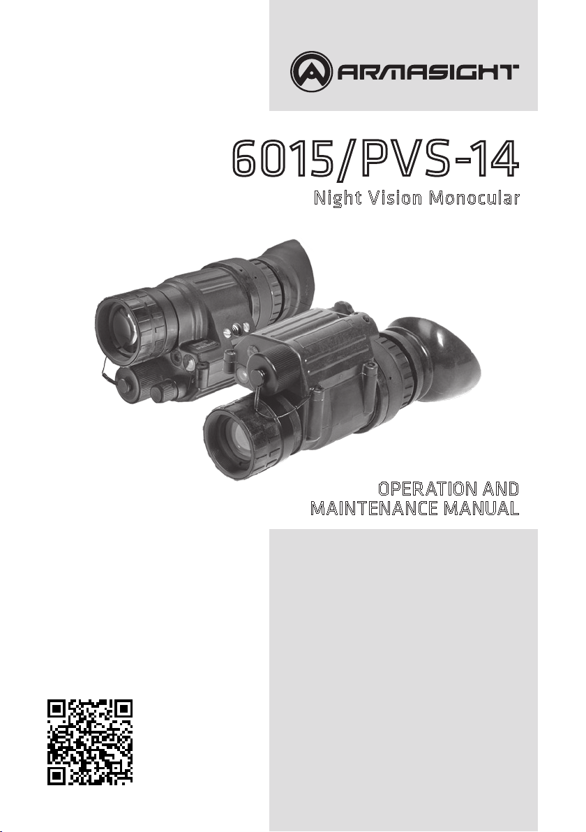
The NVMPS includes the items shown in Figures 1-1, 1-2, 1-3. The major components are the headmount, helmet mount, monocular, carrying case, and the shipping and storage case.
a. Monocular
The monocular (see Figure 2-4) consists of various components such as an objective lens, an image
intensier (not shown), an eyepiece lens and a battery cap.
The monocular also uses the accessories listed below:
Demist Shield – The demist shield (Figure 2-1) is used to prevent the eyepiece lenses from becoming fogged.
Sacricial Window – A replaceable sacricial window (Figure 2-1) is supplied to protect the objective lens during operation in adverse conditions.
Compass – The compass (Figure 2-2) enables the operator to see azimuth readings in the monocular.
Tethering Cord – The tethering cord (Figure 2-1) enables the user to attach the compass or 3X magnier to a button hole or belt loop to guard against dropping orlosing these items.
3X Magnier – (Additional Authorized Item) The 3Xmagnier (Figure 2-2) is a lens assembly which
can be added to the monocular to extend the operator’s observation ranges.
b. Headmount
The headmount (Figure 2-1) secures the monocular to the operator’s head for night viewing and provides freehand support for use with a weapon, protective mask or other purposes. It is adjustable and
cushioned. The thin browpad used for large heads, comes attached to the headmount; the thick and
medium browpads, used for smaller heads are stored in the carrying case.
Page 14
14
HEAD/HE LMET MOUNT
ADAPTER
TETHE RING
CORD
THIN BRO WPAD
HEADMOUNT
WEAPON M OUNT
BATTERY CAR -
TRIDGE
NECK CORD
OBJEC TIVE
LENS CAP
HELME T MOUNT
CARRYI NG CASE
DEMIST
EYEGUA RD
SHIELD
SACRIFICIAL
WINDOW
BAT TER Y
MONOCULAR
Figure 2-1. Components of NVMPS
COMPASS
MEDIUM A ND
THICK BR OWPADS
OPERATOR’S
MANUAL
LENS PAPER
CARRYI NG CASE
STRAP
3X MAGNIFIE R
(ADDIT IONAL ITEM)
Figure 2-2. 3X Magnier and Compass for PVS-14/6015
Page 15
15
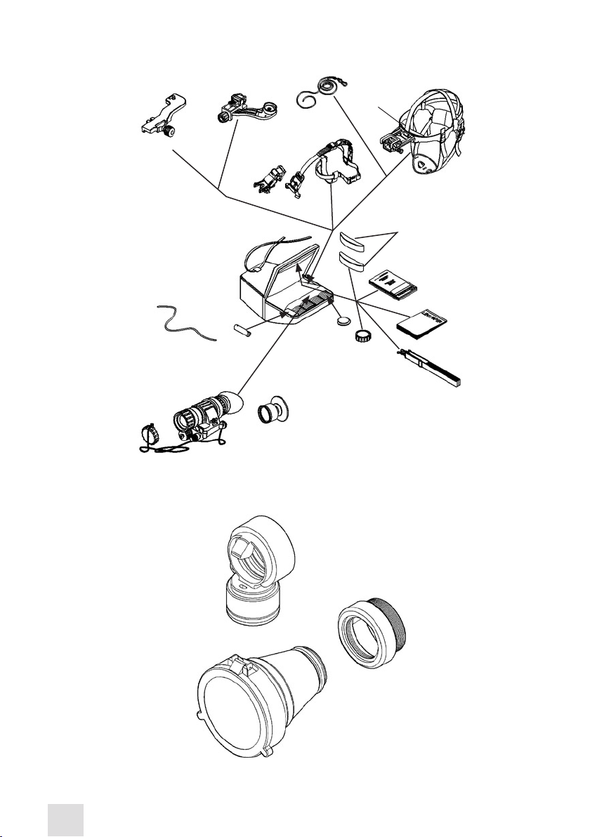
(SEE FIGUR E 2-1. FOR DETAIL S)
SHIPPING
AND
STORAG E
CASE
Figure 2-3. Shipping and storage cases for PVS-14/6015
EYEPIECE
LENS
OBJECTIVE
LENS
POWER
SWITCH
BAT TER Y
CAP
GAIN
CONTROL
Figure 2-4. Multi-Use Night Vision Monocular
c. Helmet Mount
This item (Figure 2-1), secures the monocular to the Personal Armor System Ground Troops (PASGT)
helmet allowing freehand support for use with a weapon, protective mask and/or other purposes. The
new helmet mount is made of a ruggedized metal. The old one is made of plastic.
d. Headmount/Helmet Mount Adapter
This item (Figure 2-1) is attached to the monocular to allow its use with the headmount or helmet
mount. It allows mounting in front of the lef t or right eye.
e. Weapon Mount
The weapon mount (Figure 2-1) adapts the monocular to the receiver rail as congured for the modular
weapon system kit.
f. Carrying Case
The carrying case (Figure 2-3) is provided for transportation and protection of the monocular, headmount, battery and accessories. Two slide keepers are provided for belt attachment and three D-rings
Page 16

16
for shoulder and leg strap attachment. A carrying case strap is also provided which can be attached to
the two D-rings on the back of the carrying case.
g. Shipping and Storage Case
The NVMPS is supplied in a shipping and storage case (Figure 2-3).
2.2.3. EQUIPMENT DATA
The following tables provide information pertaining to the operational, electrical, mechanical, optical,
and environmental characteristics for the monocular.
TABLE 21. OPERATOR ADJUSTMENT LIMITS
ITEM LIMITS
Diopter Focus +2 to –6 diopters
Objective Focus 25 cm to innity
TABLE 22. ELECTRICAL DATA
ITEM DATA
Power Source Battery (1.5 Vdc max ea.)
Battery Requirements 1 AA Alkaline or 1 AA 1.5 Vdc Lithium L91
TABLE 23. MECHANICAL DATA
ITEM CHARACTERISTICS
Shipping and Storage Case Size: Approx.14” X 9.5” X 8” Weight: 2.4 lbs.
Carrying Case Size: Approx. 14” X 8”
Monocular (see Note) Weight: 14 ounce
NOTE:
Weight of the monocular does not include accessories.
TABLE 24. OPTICAL DATA
ITEM DATA
Magnication 1.0X (3X with 3X magnier)
Field-of-View 40° (13° with 3X magnier)
Diopter Focus +2 to - 6 diopters
Objective Focus 25 cm (9.8”) to innity
TABLE 25. ENVIRONMENTAL DATA
ITEM DATA
Monocular Operating Temperature -51°C to +49°C
Monocular Storage Temperature -51°C to +85°C
Illumination Required Overcast starlight to moonlight
Page 17

17
2.3 PRINCIPLES OF OPERATION
2.3.1. MECHANICAL FUNCTIONS
The mechanical functions of the NVMPS allow for dierences in the physical features of individual operators and provide for operating the system. These functions include the power switch, eye relief adjustment, diopter adjustment, gain control, and objective focus. The mechanical controls are identied
in Figure 2-5.
DIOPTER
ADJUSTMENT
LAT CH
IR LENS
POWER
SWITCH
EYE RELI EF
ADJUSTMENT
OBJECTIVE
FOCUS
HIGH LIG HT CUT-OFF WINDO W
GAIN
CONTROL
Figure 2-5. Mechanical Functions for the NVMPS
NOTE:
The gain control is not present in 6015 or PVS-14NG model.
2.3.2 OPTICAL FUNCTIONS
The optical functions include an objective lens, image intensier and eyepiece lens (Figure 2-6). The objective lens collects light reected from the night scene by the moon, stars, or night sky, inverts the image and focuses that image on the image intensier. The image intensier converts the captured light
into a visible image and reinverts the image which can then be viewed through the eyepiece lens.
PHOTOCATHODE
OBJEC TIVE
LENS
MICROC HANNEL
PL ATE
PHOSPHO R
SCREEN
IMAGE
INTENSIFIER
Figure 2-6. Optical Function Diagram
FIBER- OPTIC
INVERTER
POWER
SUPPLY
EYEPIE CE
LENS
EYE
Page 18

2.3.3. ELECTRONIC CIRCUIT FUNCTION
The electronic circuit regulates the direct current voltage from the battery to the image intensier and
IR source as required. It also monitors the output voltage of the battery and turns on a low-battery
indicator when the available battery voltage is 1.9 – 2.1 Vdc.
a. Power Source
The electronic circuit is powered by one battery.
b. High Light Cut-O
The monocular will automatically cut o after 70 ±30 seconds of operation in daylight or bright room
light. Individual bright lights (headlights, ashlights, or other concentrated light sources) will not actu-
ate the high light detector located on the front of the monocular. To turn the monocular back ON, turn
the power switch to RESET/OFF position and then to ON again.
18
Page 19

19
3
OPERATING INSTRUCTIONS
3.1 DESCRIPTION AND USE OF OPERATOR’S
CONTROLS AND INDICATORS
NOTE:
The MUNVM is a precision electro-optical instrument, so handle it carefully. If the equipment
fails to operate, refer to the Troubleshooting Procedures in Chapter 4.
3.1.1. OPERATOR CONTROLS AND INDICATORS
The MUNVM is designed to adjust for dierent users and corrects for most dierences in eyesight. The controls and indicators for the MUNVM are shown in Figure 3-1, which are described in
Table 3-1.
DIOPTER
ADJUSTMENT
LAT CH
IR LENS
EYE RELI EF
ADJUSTMENT
OBJECTIVE
FOCUS
BATTERY POL ARITY
INDIC ATORS (HI DDEN)
Figure 3-1. Monocular Controls and Indicators
NOTE:
The gain control is not present in 6015 model.
HIGH LIG HT CUT-OFF WINDO W
GAIN
CONTROL
POWER
SWITCH
Page 20

20
NOTE:
Low battery indicator and IR source “on” indicator are visible in eyepiece lens.
TABLE 31. MONOCULAR CONTROLS AND INDICATORS
CONTROLS AND INDICATORS FUNCTIONS
Controls monocular and IR source, ON or OFF.
Same as system OFF. Also resets monocular after high light
cut- o.
Turn the knob clockwise to momentarily activate the IR source.
Pull and turn the knob clockwise from the ON position to continuously activate theIR source.
Power Switch
RESET/OFF
ON Monocular activated.
IR/PULL
CAUTION
Do not use excessive force to place the power switch into the momentary IR position.
Low Battery Indicator
IR Source On Indicator
Gain Control
(PVS-14 only)
Objective Focus Focuses objective lens. Adjusts for sharpest image of viewed object.
Diopter djustment
Eye Relief Adjustment Adjusts the distance between your eye and the monocular.
Latch
Battery Polarity Indicators
:
When blinking it indicates a low battery condition with less than 30 minutes
of battery life remaining. It is visible through the eyepiece just outside the
intensied eld-of-view.
When blinking it indicates a low battery condition with less than 30minutes
of battery life remaining. It is visible through the eyepiece just outside the
intensied eld-of-view.
Adjusts the system gain from a minimum value of approximately 25 to a
maximum value greater than 3,000.
Focuses eyepiece lens for use without the need for glasses. Adjust for sharpest image of intensier screen.
Latch used for separation of monocular from head-mount/helmet mount
adapte r.
This feature, molded into the battery housing, shows the proper orientation
of the batter y. Some versions have a bubble molded into the top of the battery house, to show the + for proper orientation.
Page 21

21
3.2 PREVENTIVE MAINTENANCE CHECKS AND
SERVICES PMCS
3.2.1. PREVENTIVE MAINTENANCE CHECKS AND SERVICES
a. General
To ensure the readiness of the MUNVM, perform the preventive maintenance procedures in accordance
with Table 2.2, prior to each mission. Preventive maintenance procedures include inspection, cleaning,
and performance of the checkout procedures.
b. Warnings and Cautions
Always observe the WARNINGS and CAUTIONS appearing in the table. Warnings and cautions appear
before applicable procedures. You must observe the warnings and cautions to prevent serious injury
to yourself and others, or to prevent your equipment from being damaged.
c. Explanation of Table Entries
(1) Item Number Column. Numbers in this column are for reference. When completing Equipment Inspection and Maintenance Worksheet, include the item number for the check/service indicating a fault.
Item numbers also appear in the order that you must do checks and services for the intervals listed.
(2) Interval Column. This column tells you when you must do the procedure in the procedure column.
BEFORE procedures must be done before you operate or use the equipment for its intended mission.
DURING procedures must be done during the time you are operating or using the equipment for its
intended mission. AFTER procedures must be done immediately after you have operated or used the
equipment.
(3) Location, Check/Service Column. This column provides the location and the item to be checked or
serviced. The item location is underlined.
(4) Procedure Column. This column gives the procedure you must do to check or service the item listed
in the Check /Service column to know if the equipment is ready or available for its intended mission or
operation. You must do the procedure at the time stated in the interval column.
(5) Not Fully Mission Capable If: Column. Information in this column tells you what faults will keep your
equipment from being capable of performing its primary mission. If you make check and service procedures that show faults listed in this column, do not operate the equipment. Follow standard operating
procedures for maintaining the equipment or reporting equipment failure.
NOTE:
Damaged accessory items (sacricial window, demist shield, compass) do not cause the entire
end item to be “not fully mission capable”. However, the damaged item should be replaced as
soon as practical to restore full capability of the system.
d. Other Table Entries
Be sure to observe all special information and notes that appear in your table.
Page 22

22
TABLE 31. PREVENTIVE MAINTENANCE PROCEDURES
ITEM
INTERVAL CHECK/SERVICE PROCEDURE NOT FULLY MISS ION CAPABLE IF
NO.
1 Before Open carrying case and check the
inventory items
MONOCULAR
2 Before/
After
Optical
Surfaces
Inspect all lenses (objective, eyepiece,
IR lens and high light cut-o window)
for dirt, ngerprint residue, chips, or
cracks. If necessary, clean and dry
Scratches or heav y scratches
that hinder vision with monocular turned ON, or if cracks
are present.
lenses with water and lens tissue.
3 Before/
After
Battery Cap
Housing
Inspect external surfaces for cracks
or damage. Scratches, cracks, and
gouges are OK if operation is not
Cracks or damage in the battery housing.
aected.
Inspect battery compartment. Check
to make sure batter y cap is present.
Remove battery cap and inspect
Cap is missing, contacts damaged, or corroded, o-ring is
missing.
for moisture, cracks, corroded or
defective spring contacts, and o-ring
present in cap.
Remove battery and turn the power
switch from RESET/OFF to ON to IR/
PULL. Each position should have a
denite stopping point. Inspect for
Power switch has no denite
stopping points or knob is
broken or missing.
broken or missing knob.
Install battery per paragraph 2.6. and
check IR source (and momentary IR
source, if so equipped) functions by
following the operating instructions in
IR source does not work.
paragraph 3.22.
Check the high light cut-o with
daylight or bright room light (not uo-
If damaged, refer to higher
level of maintenance.
rescent light) by placing the lens cap
on the objective lens. Turn monocular
ON and observe that the system cuts
OFF within 70 ±30 seconds.
Turn monocular OFF and then ON to
reenergize monocular.
NOTE:
If the monocular fails this highlight
cut-o test, it does not cause the
end item to be nonmission capable.
However, it should be sent to higher level of maintenance as soon as
possible.
Check gain control for free movement
and operation per paragraph 3.2.5.
Knob is not free moving or
does not vary gain.
Page 23

23
TABLE 31. CONTINU ED
ITEM
INTERVAL CHECK/SERVICE PROCEDURE NOT FULLY MISS ION CAPABLE IF
NO.
4 Before/
After
Monocular Inspect for cracks or damage. Scratch-
es, cracks, chips and gouges are OK if
Cracks or damage in the
monocular.
operation is not aected.
5 Before/
After
Eyepiece Lens Rotate diopter adjustment to make
sure the eyepiece lens moves freely
Binding, not moving freely or
too loose.
and is not loose. Range is approximately ½ turn.
6 Before/
After
7 Before/
After
Eyecup Inspect for dirt, dust, cracked or torn
eyecup. Inspect for bent, broken, or
improperly tting eyepiece lens. If
necessary, clean with water.
Eyeguard Inspect for dirt, dust, cracked or torn
eyeguard. Inspect for bent, broken, or
improperly tting eyeguard. If necessary, clean with water.
Chips and cracks are permitted
on the eyecup retaining rings
as long as they do not interfere
with installation of eyecup.
Chips and cracks are permit-
ted on the eyeguard retaining
rings as long as they do not
interfere with installation of
eyeguard.
8 Before/
After
Objective
Lens
Rotate focus ring to ensure free movement (range is approximately 1/3
turn). Check objective lens for chips,
Focus ring is binding or not
able to move.
cracks and dents.
Check the innity focus locking ring
for tightness. Check for cracks.
Chips, cracks, or dents prevent
full eld-of-view or the ability
to focus.
Cracked or loose.
9 Before/
After
Neck Cord
and Objective
Lens Cap
Inspect for cracked, torn, or missing
objective lens cap. Inspect neck cord
for cut, damage, or loose ends.
Damaged.
Re-tie ends if necessary.
10 Before/
After
Viewed Image
NOTE:
Operator may use the TS-4348/
UV to check resolution (paragraph
3.2.2).
11 Before/
After
HEADMOUNT
Straps/Pads
Refer to paragraph 2.2.3 to inspect for
operational defects.
NOTE:
Flickering, ashing, edge glow,
or shading is observed.
If any of the following items are
damaged it does not cause the en-
tire end item to be “not fully mission
capable”. However, the damaged
item should be replaced as soon as
practical to restore full capability of
the system.
Inspect for cuts, tears, fraying, holes,
cracks, or defective fasteners.
Damage causes straps or pads
to be unserviceable.
Page 24

24
TABLE 31. CONTINU ED
ITEM
INTERVAL CHECK/SERVICE PROCEDURE NOT FULLY MISS ION CAPABLE IF
NO.
12 Before/
After
Socket Inspect for dirt, dust, or corrosion.
Insert monocular latch into socket to
Damaged, latch won’t lock or
is too loose.
verify secure attachment of monocular to headmount. If necessary, clean
socket with water.
13 Before
/Af ter
Eye Relief
Adjustment
Press the eye relief adjustment and
check for free motion. Inspect for
Binding, damaged or non-
operational slide mechanism.
damage.
14 Before
/Af ter
15 Before
/Af ter
16 Before
/Af ter
17 Before
/Af ter
18 Before
/Af ter
19 Before/
After
20 Before
/Af ter
HELMET MOUNT
Straps
Inspect for cuts, tears, fraying, holes,
cracks, or defective fasteners.
Socket Inspect for dirt, dust, or corrosion.
Insert monocular latch into socket to
verify secure attachment of monocular to helmet mount. If necessary,
clean socket with water.
Fore-and-Aft
Adjustment
Press the 2 side buttons on plastic
mount or depress side lever on metal
mount and check for free motion.
Inspect for damage.
MOUNTING ADAPTERS
Headmount/
Helmet
Mount
Adapter
Inspect for dirt, dust or corrosion.
Insert into headmount or helmet
mount socket to verify secure attachment.
Weapon
Mount Inspect for dust, dirt or corrosion.
ACCESSORIES
CAUTION:
IThe coating on the demist shield
can be damaged if cleaned while
wet or if cleaned with wet lens paper. Clean only when the demist
shield is dry and only with dry pape r.
Inspect for dirt, dust, scratches or
damage. If necessary, clean when
shield is dry and with dry lens tissue
only.
Sacricial
Window
Inspect for dirt, dust, scratches or
damage. If necessary, clean per paragraph 4.2.
Damage causes straps to be
unserviceable.
Damaged, latch won’t lock or
is too loose.
Binding, damaged or non-
operational slide mechanism.
Damaged, will not latch
securely.
Damaged, will not mount to
monocular or will not mount
to rail.
Damage or scratches hinder
vision with monocular on.
Damage or scratches hinder
vision with monocular on.
Page 25

25
TABLE 31. CONTINU ED
ITEM
INTERVAL CHECK/SERVICE PROCEDURE NOT FULLY MISS ION CAPABLE IF
NO.
21 Before
/Af ter
Compass Inspect for dirt, dust, scratches, or
damage. If necessary, clean with water
Damaged or compass is not
visible.
and dry with lens tissue.
Install compass and turn on monocular. When the illumination button is
depressed, compass should be visible.
22 Before
/Af ter
3X Magnier
(Additional
Inspect optical surface for dirt, dust,
scratches or cracks.
Damage or scratches hinder
vision.
Authorized
Item)
CARRYING CASE
23 Before
/Af ter
Case
Remove all items and shake out loose
dirt or foreign material. Inspect for
tears, cuts, excess wear, or damage to
mounting clips.
24 Before
/After
Shoulder
Strap
Inspect for cuts, tears, or excess wear
or damaged clips.
3.2.2. RESOLUTION CHECK USING THE TS4348/UV TEST SET
NOTE:
The TS-4348/UV Test Set can be used by the operator to check the resolution of a monocular
at any time.
NOTE:
The TS-4348/UV Test Set can be used by Direct Support/Intermediate Level to perform the resolution testing 180 Day Service. If a system fails it must be tested on the TS-3895A/UV Test Set.
NOTE:
Verify the resolution of the monocular using the TS-4348/UV Test Set at every oppor tunity. The
resolution cannot be accurately measured without the test set.
The following procedures are designed to check the performance of the image intensier.
a. Setup
Before using the TS-4348/UV Test Set to set up and familia-rize yourself with its operation and the
warnings and cautions associated with that test equipment.
Page 26

26
NOTE:
• The resolution test must be performed in a darkened area. Your eyes must be dark-adapted to
perform this test. Review the following test procedure before entering the dark area.
• Expect cosmetic blemishes, such as chicken wire, black spots, and xed-pattern noise, to stand
out while viewing through the TS-4348/UV Test Set when it is on the high light level. This is
acceptable.
• The rejection of any MUNVM for cosmetic defects must be based on an outdoor evaluation
and not the TS-4348/UV Test Set.
b. Low Light and High Light Resolution Test Procedure
Test the monocular for low light and high light resolution performance according to the following
steps.
(1) Place the HIGH/LOW switch on the test set to the LOW position.
(2) Turn o the room light and let your eyes adjust to the dark.
(3) Turn on the test set by setting the “II/OFF/III” switch to the “III” position.
(4) Turn on the monocular and insert it into the test port on the test set.
(5) Look through the monocular and view the projected pattern (see Figure 3-2). If necessary, focus the
eyepiece lens and then the objective lens to obtain the sharpest image.
(6) The MUNVM monocular must be able to resolve Group 2, Element 2, under low light conditions to
pass the test. If the MUNVM does not pass the test, return it to maintenance for repair. The operator
must document resolution failures on the maintenance record.
1
GROUP NU MBER
5
ELEMEN T NUMBERS
READ TH IS FOR LOW
LIGHT RE SOLUTION
FOR MUNVM
NOTE
THE TARGET SH OWN IS FOR EXAMPLE ON LY AND IS NOT DR AWN
TO SCALE .
Figure 3-2. TS-4348/UV Test Set Pattern
2
2
3
4
5
6
4
2
3
4
5
6
1
3
1
2
3
5
1
2
4
3
4
5
6
5
4
1
6
2
1
READ TH IS FOR
HIGH LIG HT
6
RESOLUT ION
FOR MUNVM
NOTE:
For a pattern to be resolvable, three vertical bars and three horizontal bars must be visible.
(7) Flip the HIGH/LOW switch to the HIGH position.
(8) Again, look through the monocular and view the projected pattern (see Figure 3-2). If necessary,
refocus the objective lens and then the eyepiece lens to obtain the sharpest image.
Page 27

27
(9) The MUNVM must be able to resolve Group 3, Element 5, under high light conditions to pass the test.
If the monocular does not pass the test, send it to a higher level of maintenance for repair.
NOTE:
When using the TS-4348/UV Test Set, you are not viewing the entire image intensier. Therefore, operational and cosmetic inspections must be done without the test set as specied in
paragraph 3.2.3.
(10) Look for ashing, ickering, or other nonstable behavior of the image intensier. Also check the
image intensier for other operational defects described in paragraph 3.2.3. To view the image intensi-
er under low light conditions, ip the HIGH/LOW switch to the LOW position and allow your eyes to
become accustomed to the dark. If any unacceptable conditions are noted, send to a higher level of
maintenance for repair.
3.2.3. INSPECTION CRITERIA FOR PROPER IMAGE INTENSIFIER OPERATION
a. General
As directed in the Preventive Maintenance Checks and Services table, image intensier operation must
be checked before each mission. This section provides information for the operator concerning what to
look for, how to look for it, and how to determine if the MUNVM should be returned to the maintainer.
CAUTION:
Perform the following inspection in the dark.
To perform this inspection, attach the monocular to the headmount as described in paragraph 3.3.7
and turn the power switch to the ON position. Look through the monocular and view the image.
There are two groups of “defects” you may encounter – operational defects and cosmetic blemishes. Operational defects are an immediate cause to reject the MUNVM. Cosmetic blemishes are not a cause for rejection
unless they become severe enough to interfere with the ability to perform the mission. The rejection of any
MUNVM for cosmetic defects must be based on an outdoor evaluation and not the TS-4348/UV Test
Set.
b. Operational Defects
These defects relate to the reliability of the image intensier and are an indication of instability. If iden-
tied, they are an immediate cause for rejecting the MUNVM. They include shading, edge glow, ashing, ickering, and intermittent operation.
(1) Shading. If shading is present, you will not see a fully circular image (see Figure 3-3). Shading is very dark
and you cannot see an image through it. Shading always begins on the edge and migrates inward eventually
across the entire image area. Shading is a high contrast area with a distinct line of demarcation. Return the
MUNVM to the maintainer.
SHADING
Figure 3-3. Shading
Page 28

28
NOTE:
Make sure the shading is not the result of improper eye-relief adjustment (refer to paragraph
3.4.2).
(2) Edge Glow. Edge glow is a bright area (sometimes sparkling) in the outer portion of the viewing
area (see Figure 3- 4).
To check for edge glow, block out all light by cupping a hand over the objective lens. If the image intensier is displaying edge glow the bright area will still show up. Return the MUNVM to the maintainer.
EDGE
GLOW
Figure 3-4. Edge Glow
(3) Flashing, Flickering, or Intermittent Operation. The image may appear to icker or ash. If there
is more than one icker, check for loose battery cap or weak battery. If weak or loose batteries are not
the problem return the MUNVM to the maintainer.
c. Cosmetic Blemishes
These are usually the result of manufacturing imperfections that do not aect intensier reliability and
are not normally a cause for rejecting an MUNVM. However, some types of blemishes can get worse
over time and interfere with the ability to perform the mission. If you believe a blemish is cause for
rejection, record the specic nature of the problem on the maintenance forms and identify the position of the blemish by using the clock method and approximate distance from the center (e.g., 5 o’clock
toward the outside, 2:30 near the center, or 1:00 midway). The following are cosmetic blemishes:
(1) Bright Spots. A bright spot is a small, nonuniform, bright area that may icker or appear constant
(Figure 3-5). Not all bright spots make the MUNVM rejectable. Cup your hand over the objective lens to
block out all light. If the bright spot remains, return the MUNVM to the maintainer. Bright spots usually
go away when the light is blocked out. Make sure any bright spot is not simply a bright area in the scene
you are viewing. Bright spots are acceptable if they do not interfere with the operator’s ability to view
the image or to perform the mission.
EMISSI ON POINTS
BRIGH T SPOTS
Figure 3-5. Bright Spots and Emission Points
Page 29

29
(2) Emission Points. A steady or uctuating pinpoint of bright light in image area that does not go
away when all light is blocked from the objective lens of the monocular (Figure 3-5). The position of an
emission point within the image area does not move.
Not all emission points make the MUNVM rejectable. Make sure any emission point is not simply a point
light source in the scene you are viewing. Emission points are acceptable if they do not interfere with
the operator’s ability to view the image or to perform the mission.
(3) Black Spots. These are cosmetic blemishes in the image intensier or dirt or debris between the
lenses. Black spots are acceptable as long as they do not interfere with viewing the image. No action
is required if this condition is present unless the spots interfere with the operator’s ability to view the
image or to perform the mission.
(4) Fixed-Pattern Noise. This is usually a cosmetic blemish characterized by a faint hexagonal (honeycomb) pattern throughout the viewing area that most often occurs at high light levels or when viewing
very bright lights (see Figure 3-6). This pattern can be seen in every image intensier if the light level is
high enough. This condition is acceptable as long as the pattern does not interfere with the operator’s
ability to view the image or to perform the mission.
Figure 3-6. Fixed-Pattern Noise
(5) Chicken Wire. An irregular pattern of dark thin lines in the eld-of-view either throughout the
image or in parts of the image area (see Figure 3-7). Under the worst case condition, these lines will
form hexagonal or square-wave shaped lines. No action is required if this condition is present unless it
interferes with the operator’s ability to view the image or to perform the mission.
Figure 3-7. Chicken Wire
Page 30

30
3.3 ASSEMBLY AND PREPARATION FOR USE
3.3.1. UNPACKING
The following steps must be accomplished prior to each mission where the MUNVM is used.
CAUTION:
Relieve air pressure inside shipping and storage case by pressing in on opposite sides of the
case before releasing latches.
(1) Release the latch securing top of shipping and storage case and open.
(2) Check contents for completeness (see Figure 2-1).
(3) Remove carrying case. Open carrying case (Figure 2-3), remove MUNVM, and check contents for
completeness.
(4) Inspect the monocular for obvious evidence of damage to optical surfaces, body, eyecup, eyeguard,
power switch, battery cap, etc. Ensure that all optical surfaces are clean and ready for use. Clean with
lens paper.
3.3.2. INSTALLATION OF BATTERY
CAUTION:
To protect the image intensier, keep the objective lens cap on when the monocular is not in
use or when using the monocular in daylight conditions.
The MUNVM operates with one AA battery. Battery is not supplied with the MUNVM and must be obtained separately.
At operating temperatures below -20°C (-4°F), Alkaline batteries are not recommended, as operating
life will be severely reduced. Lithium-iron disulde L91 1.5V AA batteries should be used below -20°C
(-4°F).
TABLE 32. ESTIMATED BATTERY LIFE
BATTERY TYPE TEMPERATURE NEGLIGIBLE
IR SOURCE USAGE
AA Alkaline 21°C(70°F) 60 Hrs 55 Hrs
AA Lithium L91 21°C( 70° F) 70 Hrs 65 Hrs
AA Alkaline -20 °C(- 4°F) 12 Hrs 10 Hrs
AA Lithium L91 -20 °C(- 4°F) 60 Hrs 55 Hrs
CAUTION:
Make certain the power switch is in the OFF position before installing the battery.
Install the AA battery into PVS14 or 6015 as follows.
(1) Unscrew the battery cap.
(2) Observe polarity, as indicated on the side of the battery compartment and insert the battery.
IR SOURCE
USAGE 10% OF TH E TIME
Page 31

31
(3) Replace the battery cap and screw cap hand tight.
SACRIFICIAL
WINDOW
EYECUP
DEMIST
SHIELD
BATTERY CAP
BATTERY
EYEGUA RD
Figure 3-8. Battery, Eyecup and Eyeguard Installation
3.3.3. INSTALLATION OF EYECUP OR EYEGUARD
Perform the following procedure to install eyecup or eyeguard onto the monocular. Refer to Figure
3-8.
(1) Carefully press the eyecup or eyeguard over the end of the eyepiece lens.
(2) Rotate the eyecup or eyeguard into proper viewing position. Adjust for best t. The eyecup must
seal around your eye and prevent the green glow from escaping.
3.3.4. INSTALLATION OF DEMIST SHIELD
Perform the following procedures to install the demist shield on the eyepiece lens. Refer to Figure 3-8.
CAUTION:
If the demist shield needs to be cleaned, refer to paragraph 4.3.1 for cleaning. If the demist
shield is wiped while wet or with wet lens paper, you will damage the coating.
NOTE:
If inclement operating conditions are expected to exist (e.g. signicant temperature change
and high humidity), install demist shield to minimize eyepiece lens fog prior to execution of
mission.
(1) Carefully remove the eyecup or eyeguard.
(2) Carefully press the demist shield onto the eyepiece. Be careful not to smudge the eyepiece lens or
demist shield.
(3) Replace the eyecup or eyeguard (see paragraph 3.3.3).
3.3.5. INSTALLATION OF SACRIFICIAL WINDOW
Perform the following procedure to install the sacricial window. Refer to Figure 3-8.
CAUTION:
If adverse operating conditions (dust or sand) are expected to exist, attach the sacricial window to protect the objective lens from scratches or other damage.
Page 32

32
(1) If the objective lens cap is in place, remove it.
(2) Carefully push the sacricial window onto the objective lens until it stops. Turn the sacricial window clockwise until it snaps into place.
3.3.6. INSTALLATION AND ADJUSTMENT OF HEADMOUNT
Perform the following procedures for donning the headmount.
NOTE:
Do not don the headmount while the monocular is attached.
(1) Prior to donning the headmount, loosen the four ends of the chinstrap approximately two inches
from the sliding bar buckles (Figure 3-9).
(2) Snap the front and rear snaps (Figure 3-9) in place.
NOTE:
If the headmount is too loose, remove the attached thin browpad (Figure 4-3) and replace with
either the medium or thick browpad stored in the carrying case. Refer to paragraph 4.3.2 for
removal and replacement of the browpads.
(3) With both hands grasp the neck pad (Figure 3-9) and pull the harness over your head and the neck
pad down to the back of your neck.
(4) Holding the chin cup in position on chin, adjust both sides of the chinstrap until you feel light pressure against your chin. (DO NOT TIGHTEN.)
(5) Maintain the position of the chin cup and remove any slack from the chinstrap. (DO NOT TIGHTEN.)
CROSS-STRAP
CHIN CUP
VERTICAL
ADJUSTMENT
(HIDDEN)
SLIDIN G BAR
BUCKLES
CHINSTRAP
ADJUSTMENT
AND SNAP
NECK PAD
CHINST RAP
ADJUSTMEN T
AND SNAP
CHINST RAP
ADJUSTMENT
BROWPAD
(THICK , MEDIUM
OR THIN)
HEADMO UNT
SOCKET
EYE RELI EF
ADJUSTMENT
CHINST RAP
ADJUSTMENT
HEADBAND
Figure 3-9. MUNVM Headmount Adjustments
(6) Ensure that the cross-strap is not twisted and remove slack by adjusting the vertical adjustment at
the neck pad.
(7) Adjust chinstrap and vertical adjustment until the chin cup and headband are in a comfortable but
rm position.
Page 33

33
NOTE:
After installing the monocular, minor strap adjustments may be necessary to achieve comfort.
(8) Install the headmount/helmet mount adapter (refer to paragraph 3.3.7).
(9) Refer to paragraph 3.4.2. for operating procedures.
3.3.7. INSTALLATION OF HEADMOUNT/HELMET MOUNT ADAPTER
Install the headmount/helmet mount adapter (Figure 2-1) into the monocular by aligning thumbscrew
to hole and tightening as shown in Figure 3-10. There is an alignment boss on the headmount/helmet
mount adapter that ts into a groove on the monocular. Make sure the boss on the adapter ts into the
groove on the monocular.
THUMBSCREW
LAT CH
ALIGNM ENT BOSS
(HIDDEN)
ALIGNM ENT BOSS
GROOVE
Figure 3-10. Headmount/Helmet Mount Adapter Installation
3.3.8. INSTALLATION OF HELMET MOUNT TO HELMET
(1) Remove the helmet mount from the carrying case. Refer to Figure 3-11 for helmet mount features.
(2) Press the release (Figure 3-12) to remove the mount from the helmet mount bracket.
(3) Make sure the strap is laced onto the helmet mount bracket as shown in Figure 3-12.
(4) With catch (see Figure 3-12) in forward most position, place the strap over the top of the helmet
center (see Figure 3-13).
(5) Hook the rear bracket (see Figure 3-12) on the center of the back of the helmet and lay the strap with
helmet mount bracket over the top of the helmet.
(6) Hook the helmet mount bracket in the center of the front lip of the helmet and hold it in place (see
Figure 3-13).
(7) With the buckle lever open, take up the slack in the strap using the catch. Close the buckle lever.
(8) Disengage the nape strap latch on the left side of nape strap.
(9) Don the helmet. Do not fasten the helmet chinstrap.
(10) Engage the nape strap at the nape strap latch. Tension the nape strap for a stable t, then install
and tension the helmet chinstrap. The brow of the helmet should be parallel to the ground and the
helmet stable on the head.
Page 34

34
(11) Insert the top edge of the mount under the keeper on the helmet mount bracket and rotate downward until the latch engages (see Figure 3-13). To release the mount from the helmet bracket, press the
release and pull forward and down.
KEEPER
NAPE
STRAP
HELMET
MOUNT
BRACK ET
REAR
MOUNTING
HOLE
CAT CH
BUCKLE
LEVER
STRAP
REAR
SNAP
REAR
BRACK ET
Figure 3-11. Installation of Helmet Mount
TOP EDGE
OF MOUNT
MOUNT IS R OTATED
MOUNT
RELEASE
90° FOR CL ARITY
KEEPER
HELMET
MOUNT
BRACK ET
STRAP
Figure 3-12. Helmet Mount
TOP EDGE
OF MOUNT
RELEASE
MOUNT
LAT CH
HELMET
MOUNT
BRACK ET
KEEPER
Figure 3-13. Reassembly of Helmet Mount
3.3.9. INSTALLATION OF HEADMOUNT WITH PROTECTIVE MASK
Perform the following procedures for donning headmount with protective mask.
(1) Place protective mask on your head per the instructions provided with the protective mask.
Page 35

35
WARN ING:
When installing the headmount over the protective mask, be careful not to break the protective
mask seal around your face.
(2) Install the headmount per the instructions in paragraph 3.3.6.
NOTE:
It may be necessary to remove the browpad (Figure 3-9) when wearing the headmount over a
protective mask.
3.3.10. INSTALLATION OF WEAPON MOUNT
Perform the following procedure to install the weapon mount.
WEAPON
MOUNT
THUMBSCREW
ALIGNM ENT BOSS
(HIDDEN)
CLAMPI NG KNOB
Figure 3-14. Weapon Mount Usage
CAUTION:
The MUNVM is not a weapon sight, however, it can be used in conjunction with a collimated dot
sight or laser aiming device.
NOTE:
It is recommended that the eyecup be replaced with the eyeguard during weapon mounted
use.
(1) Orient the monocular and weapon mount as shown in Figure 3-14. Be sure to align the alignment
boss on the weapon mount with the alignment groove in the monocular.
(2) Screw in the thumbscrew to secure the monocular to the weapon mount.
(3) Loosen the clamping knob on the weapon mount. Position the weapon mount with the monocular
onto the weapon’s mounting rail. Tighten by turning the clamping knob.
Page 36

36
NOTE:
There is a ratchet in the weapon mount that prevents overtightening of the clamp. Turn until
the knob clicks.
(4) Check the position of the monocular by holding the weapon in your normal ring position. Adjust
the fore/aft position of the monocular as necessary by loosening the clamping knob and repositioning
the weapon mount on the weapon’s mounting rail.
3.3.11. INSTALLATION OF COMPASS
CAUTION:
• Use of the compass with the plastic headmount or the plastic helmet mount will result in inaccurate compass readings. The magnet cannot be removed from these mounts.
• The magnet must be removed from the ruggedized metal helmet mount before installation of
the compass. Failure to do so will result in inaccurate compass readings.
• If the magnet is not removed, turn the ruggedized metal helmet mount in to unit maintenance
for removal. See Figure 3-15 for location of magnet.
(1) If the sacricial window or objective lens cap is in place, remove it.
(2) Turn monocular on.
(3) Rotate the objective lens focus completely counterclockwise (while looking through the monocular).
MAGNET
Figure 3-15. Locating the Magnet
Figure 3-16. Compass Installation
Page 37

37
NOTE:
The o-ring must be in place in the compass in order for the compass to t properly.
(4) Press the compass onto the objective lens at an angle using your left hand. Slowly turn the compass
counterclockwise until it is in the vertical position (with compass illumination button pointing down).
See Figure 3-16.
(5) Ensure that the compass ts tightly to the objective lens.
(6) Refer to paragraph 3.4.6 for operation of the compass.
3.3.12. INSTALLATION OF 3X MAGNIFIER
The 3X magnier can be threaded directly into the objective lens. It can also be threaded into the focus
ring adapter and slipped on over the end of the objective lens.
Figures 3-17 and 3-18 illustrate these installation procedures.
THREA D DIRECTLY INTO
OBJEC TIVE LENS AS SHOW N
Figure 3-17. 3X Magnier Installation
FOCUS RIN G
3X MAGNIFIE R
ADAPTER
STEP 1
STEP 2
THREA D 3 X MAGNIFIER
INTO FOCUS R ING ADAPTER
Figure 3-18. 3X Magnier Installation with Focus Ring Adapter
3.4 OPERATING PROCEDURES
This section contains operating procedures for using the NVMPS as hand-held, head mounted, helmet
mounted or weapon mounted monocular. Prior to operating the monocular, make certain that all the
steps in 3.3.3, Assembly and Preparation for Use, have been read and performed.
3.4.1. HANDHELD OPERATION
Operate the monocular only under darkened conditions or use the objective lens cap to cover the
objective lens for daylight conditions.
Page 38

38
NOTE:
When using the monocular without a mounting device, make sure to place the neck cord
around your neck.
(1) Ensure that the battery are installed per paragraph 3.3.2.
(2) Turn the power switch to ON.
NOTE:
The sharpest image will be observed only when the objective lens and eyepiece lens are properly focused.
(3) Rotate the diopter adjustment for the clearest view of the image intensier screen.
(4) Focus the objective lens while observing an object until the sharpest image is obtained.
3.4.2. HEAD MOUNTED OPERATION
Perform the following procedures for head mounted operation.
CAUTION:
Operate the monocular only under darkened conditions or use the lens cap to cover the objective lens for daylight conditions.
(1) Ensure that batteriy are installed per paragraph 3.3.2.
(2) Don the headmount per instructions in paragraph 3.3.6.
NOTE:
To make it easier to align the monocular, eyecup, and eyepiece lens to the eye, depress the eye
relief adjustment and slide the headmount socket all the way forward before attaching the
monocular.
HEADMOUNT
SOCKET
LAT CH
EYE
RELIEF
ADJUSTMENT
Figure 3-19. Headmount/Helmet Mount Adapter Operation
Page 39

39
(3) Align the headmount/helmet mount adapter’s latch to the headmount socket (Figure 3-19). Press
and hold down the latch lever while installing the monocular into the headmount socket.
Release the latch when the monocular fully engages the socket.
(4) Set your eye relief by depressing the eye relief adjustment (Figure 3-19.) and move the monocular
back toward your non-do-minate eye until the eyecup comfortably seals around the eye.
(5) Turn the monocular ON.
(6) Readjust the vertical adjustment (Figure 3-9) of the headmount until the monocular is properly
aligned with your eye.
NOTE:
The sharpest image will be observed only when the objective lens and eyepiece lens are properly focused.
(7) Rotate the diopter adjustment for the clearest view of the image intensier screen.
NOTE:
Any readjustment of eye relief requires readjustment of the diopter.
(8) Adjust the eye relief distance by pressing the eye relief adjustment and sliding monocular fore or aft
to obtain a full eld-ofview
of the image. Reset the diopter adjustment for best image.
(9) Adjust the objective lens focus (Figure 3-1) while observing an object until the sharpest image is
obtained.
3.4.3. HELMET MOUNTED OPERATION
CAUTION:
Take some precaution when using/handling the helmet mount. Most damage occurs when the
helmet mount is left on the helmet when not needed for immediate use. Observe the following
cautions to signicantly extend the useful life of the helmet mount.
CAUTION:
• Do not use excessive force when changing the up/down position of the MUNVM. Excessive
force can break the headmount/helmet mount adapter.
• Do not drop or throw the helmet with the helmet mount attached to it.
• With the monocular in the ipped up position, do not ick the monocular down by shaking the
helmet. This places signicant stress on the helmet mount.
• All Other Services – Return the helmet and the helmet mount to unit maintenance for direct
mounting of the bracket via the helmet screws.
NOTE:
The headmount/helmet mount adapter allows the MUNVM to be rotated from the left to the
right eye or vice versa. The MUNVM can be moved to the ipped up position with the headmount/helmet mount adapter positioned to either the left or the right.
Page 40

40
NOTE:
The helmet mount provides two positions for the user to position the MUNVM. The ipped
down position allows the user to position the MUNVM directly in front of the eyes. The helmet
mount also allows the user to rotate the MUNVM to a ipped up position when the MUNVM is
not needed for immediate use. Both the ipped down and the ipped up positions have a posi-
tive stop which assures the user that the MUNVM is in the correct position.
Perform the following procedures for helmet mounted operation.
(1) Ensure that the battery are installed per paragraph 3.3.2.
(2) Don the helmet mount per instructions in paragraph 3.3.8.
(3) Place the monocular in the socket of the helmet mount.
Set your eye relief by depressing the side buttons (or press down on side lever on metal mount) (see
Figure 3-20) and carefully move the monocular fore or aft until the eyecup comfortably seals around
the eye. Readjust the helmet straps as required for vertical adjustment.
PLASTI C MOUNT
TILT ADJUSTME NT
LOCK KNO B
SOCKET
SIDE
BUTTO NS (2 EA)
(FORE-AN D-AFT
ADJUSTMENT)
METAL MOUN T
TILT ADJUSTME NT
LEVER
SOCKET
SIDE LEV ER
(FORE-AN D-AFT
ADJUSTMENT)
Figure 3-20. Tilt and Flip-up Assembly Mechanisms
(4) Turn power switch to ON. Adjust the tilt by using the tilt adjustment lock knob (or tilt adjustment
lever on metal mount) (Figure 3-20) until you obtain a comfortable viewing angle.
NOTE:
The sharpest image will be observed only when the objective lens and eyepiece lens are properly focused.
(5) Rotate the diopter adjustment for the clearest view of the image intensier screen.
NOTE:
Any readjustment of eye relief requires readjustment of the diopter.
(6) Adjust the eye relief distance by depressing the side buttons (Figure 3-20) (or press down on side
lever on metal mount) and sliding monocular fore or aft to obtain a full eld-of-view of the image. Reset
the diopter adjustment for best image.
(7) Adjust the objective lens focus (Figure 3-1) while observing an object until the sharpest image is
obtained.
(8) To ip up, grasp the helmet tilt and ip-up assembly and rotate upward and rearward until the latch
is rmly engaged.
Page 41

41
WARN ING:
The monocular will not be turned o automatically when ipped up. The monocular must be
turned o by the power switch.
(9) To ip down, grasp the helmet tilt and ip-up assembly and rotate downward and forward until the
latch is rmly engaged.
(10) Turn the power switch to the ON position to resume viewing.
3.4.4. WEAPON MOUNTED OPERATION
NOTE:
The MUNVM can be used in conjunction with a collimated dot aiming device mounted on the
forward mounting rail. The brightness control for the aiming device should be set at or near it’s
minimum setting.
Perform the following procedures for weapon mounted operation:
(1) Ensure that the battery are installed per paragraph 3.3.2.
(2) Assemble the weapon mount to the monocular per paragraph 3.3.10, steps 1 and 2.
(3) Mount the monocular with adapter onto the M16/M4 receiver rail per paragraph 3.3.10, steps 3 and
4.
(4) Rotate the diopter adjustment for the clearest view of the image intensier screen.
(5) Adjust the objective lens focus (Figure 3-1) while observing an object until the sharpest image is
obtained.
3.4.5. IR SOURCE OPERATIONS
WARN ING:
The IR source is a light that is invisible to the unaided eye for use during conditions of extreme
darkness. However, the light from the IR source can be detected by the enemy using night vision devices.
NOTE:
The purpose of the IR source is for viewing at close distances up to 3 meters when additional
illumination is needed.
(1) Pull the power switch knob out and rotate clockwise to the IR position. With the monocular held to
the eye, observe that a red light appears in the eyepiece. This indicates that the IR source is operating.
(2) For momentary IR, turn the power switch clockwise (without pulling) past the ON position. Observe
that a red light appears in the eyepiece.
3.4.6. OPERATION WITH COMPASS
WARN ING:
The compass illuminator can be seen by others using night vision devices.
Page 42

42
CAUTION:
You will get inaccurate readings, when using the compass on any head or helmet mount with
the magnet still installed. Only the magnet on the metal mount can be removed without causing damage to the equipment, see paragraph 3.3.11.
NOTE:
• The compass reading is the magnetic North, not true North.
• The compass reading is within 2° of correct absolute magnetic bearing. Compass readings
with mounted monocular (head mount or helmet mount) can be up to 15° of correct absolute
magnetic bearing. This occurs mostly in the East (90°) to West (270°) and less in the North (360°)
to South (180°) reading. If the compass is inadvertently magnetized this could cause an additional 15° error.
• The objective lens focus can be ne tuned after installation, but in order to obtain an accurate
reading, the compass must be vertical. (The compass image must be level.)
(1) Install per paragraph 3.3.11.
(2) If necessary to more clearly view your distant object, adjust the objective lens focus slightly by gripping the compass and turning clockwise.
NOTE:
• Increase brightness slowly. Excessive brightness may burn a temporary image into the image
intensier. Do not increase brightness any more than is necessary to clearly read the compass
heading.
• The monocular must be focused at or near innity for proper compass operation.
Figure 3-21. View Through Installed Compass
(3) To view the compass through the monocular, grip the compass with index nger on top and thumb
on illumination button on bottom. Press button slowly with thumb until proper brightness is obtained.
The image should appear as shown in Figure 3-21.
(4) The compass readings should change when you move your head from side to side. Rotate or tap
compass slightly to ensure compass is operating correctly. Hold the monocular in a level position to
assure free rotation of the compass scale.
(5) The tick mark closest to the center of the lighted display is the compass bearing. The tick marks are
in degrees, with longer tick marks every ve degrees and bearing labels every 10 degrees.
Page 43

43
3.4.7. OPERATION WITH 3X MAGNIFIER
(1) Install per paragraph 3.3.12.
NOTE:
The mated 3X magnier and objective lens will turn as a unit to allow focusing.
(2) Grasp the 3X magnier and focus while observing an object until the sharpest image is obtained.
3.4.8. OPERATION WITH GAIN CONTROL PVS14 ONLY
Turn the gain control (Figure 3-22) to balance the illumination input to the eye.
GAIN CONT ROL
Figure 3-22. Gain Control
3.4.9. PREPARATION FOR STORAGE
(1) Shutdown. Perform the following procedures to shut down the monocular.
(a) Turn the monocular power switch to the OFF position.
(b) Remove the monocular from the headmount, helmet mount or weapon and remove the
weapon mount from the monocular.
WARN ING:
Do not carry batteries in pockets containing metal objects such as coins, keys, etc. Metal objects can cause the batteries to short circuit and become very hot.
(2) Packaging After Use.
(a) Remove battery cap and remove battery.
(b) Inspect the battery housing for corrosion or moisture. Clean and dry if necessary.
(c) Replace the battery cap.
(d) Remove the demist shield or sacricial window if installed. Install objective lens cap.
NOTE:
• Prior to placing MUNVM into carrying case, ensure MUNVM and case are free of dirt, dust, and
moisture.
• The monocular and helmet mount should not be lef t on the helmet when the helmet is removed.
Page 44

(e) Refer to Figure 2-1 for proper placement of demist shield, batter y, carrying case strap, lens
paper, sacricial window, manual, browpads, headmount, helmet mount, headmount/helmet mount
adapter and weapon mount.
(f) Place the monocular into the shallow pocket of the carrying case.
(g) Place the carrying case into the shipping and storage case, close and latch (Figure 2-3).
(h) Return to storage area.
3.5 OPERATION UNDER UNUSUAL CONDITIONS
3.5.1. OPERATION IN DUSTY OR SANDY AREAS
CAUTION:
Operation in dusty or sandy areas can pit and scratch the optical elements and damage the
mechanical components unless the precautions given below are observed.
(1) Ensure that the sacricial window is in place.
(2) Avoid pointing the monocular into the wind unless necessary for operation.
(3) Keep the carrying case closed unless removing or replacing items.
(4) Ensure that all dust and sand is removed from the MUNVM and carrying case af ter operation.
3.5.2. OPERATION IN RAINY OR HUMID CONDITIONS
CAUTION:
Operation in rainy or humid conditions can cause corrosion and deterioration of the MUNVM
unless the precautions given below are observed.
(1) Install the demist shield (paragraph 3.3.4).
(2) Keep the carrying case, and shipping and storage case closed unless removing or replacing items.
(3) Dry the monocular, mounts, and accessories after exposure to rain or high humidity and before storage. This will prevent mildew from forming in the case.
(4) Do not store monocular in a wet carrying case or a wet shipping and storage case.
3.5.3. OPERATION IN SALT WATER AREAS
After exposure to salt water, clean the MUNVM (paragraph 4.3.1).
3.5.4. OPERATION IN NUCLEAR, BIOLOGICAL AND CHEMICAL ENVIRON
MENTS
WARN ING:
Do not use contaminated eyecup or eyeguard. They must be replaced.
(1) Decontamination – Wear a protective mask while using MUNVM after decontamination process.
(2) Hardness – Do not use DS-2 for decontaminating the MUNVM. To decontaminate, use 5% sodium
hypochlorite and rinse with hot (158° F) soapy water.
44
Page 45

45
4
PREVENTIVE MAINTENANCE AND
TROUBLESHOOTING
4.1 LUBRICATION INSTRUCTIONS
No lubrication is required.
4.2 TROUBLESHOOTING PROCEDURES
4.2.1. TROUBLESHOOTING
Table 4.1. lists common malfunctions that you may nd with your equipment. Perform the tests, inspections and corrective actions in the order they appear in the table.
This table cannot list all the malfunctions that may occur, all the tests and inspections needed to nd
the fault, or all the corrective actions needed to correct the fault. If the equipment malfunction is not
listed or actions listed do not correct the fault, notif y your maintainer.
TABLE 41. OPERATOR’S TROUBLESHOOTING
MALFUNCTION TEST OR INSPECTION CORRECTIVE ACTION
1. Monocular fails to activate. Visual.
Check for defective, missing or
improperly installed battery.
2. IR source fails to activate. In a dark location with system turned
3. IR source indicator fails to
activate.
4. Poor image quality. Check objective lens or eyepiece lens
5. Light visible around eyecup. Check eye relief distance.
on, activate IR source.
Visually check IR source operation;
scene should brighten.
Visual. Refer to higher level of maintenance.
focus.
Check for fogging or dirt on objective
lens or eyepiece lens.
Check eyecup for resiliency.
Turn power switch to RESET/OFF position and then ON.
Replace battery or install correctly.
If IR source still fails to activate, refer
to higher level of maintenance.
Refocus.
Clean lens surfaces per paragraph 4.2.
Readjust for proper eye relief
distance.
If eyecup is defective, refer to higher
level of maintenance.
Page 46

46
TABLE 41. CONTIN UED
MALFUNCTION TEST OR INSPECTION CORRECTIVE ACTION
6. Diopter adjustment cannot
be made.
7. Battery cap dicult to open. V isually inspect for the presence of
8. Head straps cannot be tightened.
9. Headmount or helmet mount
socket and headmount/ helmet mount adapter latch does
not catch.
10. Helmet mount will not
tighten to helmet.
11. If damaged, refer to higher
level of maintenance.
12. Compass will not stay on
the goggles.
13. Compass display is not
cle ar.
14. Monocular does not cut o
when exposed to high light.
Check to see if the diopter adjustment is bent or broken.
an o-ring.
Check for damaged batter y cap.
Check for defective buckles, fasteners or straps.
Check socket or latch for dirt.
Check socket or latch for damage.
Inspect mounting hardware for
damage.
Visual. Refer to higher level of maintenance.
Visual. Refer to higher level of maintenance.
Visual Make sure the monocular is focused
Visual.
Perform the following test under
daylight or bright room light (not
uorescent light).
Place the objective lens cap on the
objective lens. Turn monocular ON
and obser ve that it cuts o within 70
±30 seconds after energized.
Turn monocular OFF and then ON to
reenergize monocular.
If damaged, refer to higher level of
maintenance.
If o-ring is missing, refer to higher
level of maintenance.
If damaged, refer to higher level of
maintenance.
If damaged, refer to higher level of
maintenance.
Clean socket and latch.
If damaged, return either headmount
or helmet mount socket and headmount/ helmet mount adapter to
higher level of maintenance.
If damaged, refer to higher level of
maintenance.
for innit y. If so, and compass display
is still not clear, refer to higher level of
maintenance.
If damaged, refer to higher level of
maintenance.
4.3 OPERATOR’S MAINTENANCE PROCEDURES
4.3.1. CLEANING THE MUNVM
CAUTION:
• The monocular is a precision electro-optical instrument and must be handled carefully.
• Do not scratch the external lens surfaces or touch them with your ngers.
• Wiping demist shield with lens paper while wet or with wet lens paper can damage the coat-
ing.
Clean monocular with water if necessary and dry thoroughly. Clean lenses with lens paper (and water if
necessary, except for the demist shield).
Page 47

47
4.3.2. HEADMOUNT MAINTENANCE
a. Browpad Replacement
Replace the browpad when cracked, torn, or contaminated. Perform the following procedures to remove and replace the browpad.
(1) Firmly grasp the headmount and remove the old browpad.
(2) Gently press on the new browpad. Lightly smooth out any wrinkles in the new browpad.
b. Neck Pad Reinstallation
During operation of the MUNVM, it is possible for the neck pad to become separated from its position
on the headband. Perform the following procedure to reinstall the neck pad.
(1) Lift the upper headband strap retention tab (see Figure 4-1) allowing the neck pad strap to be inserted underneath.
(2) Slip the neck pad strap all the way under the upper strap retention tab and then pull the lower part
of the neck pad strap under the lower strap retention tab.
(3) Repeat steps 1 and 2 for the other side of the headband and neckband if necessary.
NECK PAD STRA P
UPPER STR AP
RETEN TION TAB
LOWER STR AP
RETEN SION TAB
Figure 4-1. Reinstalling the Neck Pad
c. Lacing the Sliding Bar Buckles
MOVEABLE
SLIDIN G BAR
Figure 4-2. Threading the Sliding Bar Buckles
FIXED
SERRATED B AR
Page 48

While donning and adjusting the headmount, it is possible for a strap to slip out of a slide fastener.
Perform the following procedure to adjust the strap and sliding bar buckle.
(1) Thread the strap from the inside of the buckle over the moveable sliding bar (see Figure 4-2.). Thread
the strap back through the buckle but this time under the moveable sliding bar and over the serrated
part of the buckle.
(2) Pull the strap through the buckle and tighten as necessary.
(3) Repeat steps 1 and 2 for other straps and buckles that may have come undone.
4.3.3. NECK CORD MAINTENANCE
The neck cord (Figure 2-1) may be broken, frayed, or loose at one or both ends.
If loose, re-tie cord. If broken or severely frayed, install new cord as follows:
(1) Insert ends through monocular holes from the rear.
(2) Thread right cord end through hole in objective lens cap.
(3) Tie a knot in each end.
4.4 SERVICE/PACKING AND UNPACKING
4.4.1 RETURN INSTRUCTIONS
For service, repair or replacements, please email service@armasight.com.
To assist the Service Representative (SR) with determining if the item is repairable, please provide the
following information:
(1) Serial Number of the defective item.
(2) Thorough description of the malfunction, defect or damage.
(3) An explanation of how the malfunction, defect or damage occurred, if known.
If the SR determines that the item is under warranty or should be returned for repair, a Return Material
Authorization number (RMA#) will be provided.
When returning the PVS-14/6015 for service or repair, the following procedures should be followed to
prevent any additional damage:
(1) Verify that the PVS-14 is free of all contaminants such as dirt or any other foreign material.
(2) Remove the batter y.
(3) Place the cap over the lens.
(4) Place the PVS-14/6015 in the hard shipping/ storage case or soft carrying case (if available). If the
hard shipping/ storage case is not available, individually package each PVS-14 unit being returned in
a suitable container.
Place the PVS-14/6015 and a copy of the test report or detailed description of the failure in a suitable
packing/ shipping container. Mark the package with the RMA#. Ship the items using the fastest, most
easily traceable, prepaid method to Armasight Inc., 815 Dubuque Avenue, South San Francisco, CA
94080, USA.
48
Page 49

49
APPENDIx
A. COMPONENTS OF END ITEM COEI AND BASIC ISSUE
ITEMS BII LISTS
A1. SCOPE
This appendix lists COEI and BII for the PVS-14/6015 to help you inventory items for safe and ecient
operation of the equipment.
A2. GENERAL
The COEI and BII information is divided into the following lists. Components of End Item (COEI). This list
is for information
purposes only and is not authority to requisition replacements.
These items are part of the PVS-14/6015. As part of the end item, these items must be with the end
item whenever it is issued or transferred between property accounts. Items of COEI are removed and
separately packaged for transportation or shipment only when necessary. Illustrations are furnished to
help you nd and identify the items.
Basic Issue Items (BII). These essential items are required to place the PVS-14/6015 in operation, operate it, and to do emergency repairs. Although shipped separately packaged, BII must be with the
PVS-14/6015 during operation and when it is transferred between property accounts. Listing these
items is your authority to request/requisition them for replacement based on authorization of the end
item by the TOE/MTOE. Illustrations are furnished to help you identify the items.
A3. EXPLANATION OF COLUMNS IN THE COEI LIST AND BII LIST
Column (1), Illus. Number. Gives you the number of the item illustrated.
Column (2), National Stock Number. Identies the stock number of the item to be used for requisitioning purposes.
Column (3), Description CAGEC and Part Number. Identies the Federal item name (in all capital letters) followed by a minimum description when needed. The stowage location of COEI and BII is also
included in this column. The last line below the description is the CAGEC (commercial and Government
entity code) (in parenthesis) and the part number.
Column (4), Usable on Code. When applicable, gives you a code if the item you need is not the same for
dierent models of equipment.
Column (5), U/M (Unit of Measure). Indicates how the item is issued for the National Stock Number
shown in column (2).
Column (6), Qty Rqr. Indicates the quantity required.
Page 50

50
4
3
1
2
5
8
7
6
10
9
20
11
12
15
16
19
13
17
14
18
Figure A-1.Components of End Item
TABLE A1. COMPONENTS OF END ITEM
1
ILLUS.
NUMBER
1 MONOCU LAR ASSEMBLY(80063) A32563 40 EA 1
2 5855 -01-246- 8271 WINDOW, SACRI FICIAL(80063) A3144264 EA 1
3 5855-01-444-1230 LENS, INFR ARED RECEIVER(80 063) A3256353 EA 1
4 5 855- 01-3 79-1410 FI LTER, INF RARED LIGHT(54 490) 5009737 EA 1
5 5855-01-246-8266 HEADSET AS SEMBLY(80063) A3144268 EA 1
6 5 855- 01-297-78 47 BROWPAD ASSY, THICK(80 063) A3144436 EA 1
7 5855 -01-355-8 600 BROWPAD ASSY, MEDI UM(80063) A3144435 EA 1
8 5855 -01-355-8 599 BROWPAD ASSY, THIN (80063) A3144280 EA 1
9 5965-01-444-1216 ADAPTER, H EADSET(80063) A3256 347 EA 1
10 5340-01-446-8588 BRACK ET, MOUNTING(80 063) A3256348 EA 1
11
12 5855 -01-381- 6052 COMPASS ASS EMBLY(80063) A 3187430 EA 1
13 6650- 01-444 -1229 EYEGUARD, O PTICAL INSTR UMENT(80063) A3256345 EA 1
14 534 0- 01-45 1-7737 CLIP, RETAINING(8 0063) A3260933 EA 1
15 5855 -01-39 8-428 4 CA SE, INFRARED EQU IPMENT(80063) A3187392 EA 1
16 534 0-01 -250-24 31 STRA PPING(80063) A3144267 EA 1
17 5340 -01-397-6608 CAP, PROTECT IVE, DUST(80063) A 3144318 EA 1
18 4020-01-446-8097 CORD, FIBR OUS(80063) A3144306 EA 1
19 OPERATOR’S M ANUALTM 11-5855-306-10 EA 1
20 CASE, SHIPPING & S TORAGE(80063) A326 4350 EA 1
2
NATIONAL STOCK
NUMBER
5855 -01- 457-2953
5855 -01-4 41-04 01
3 DESC RIPTION, CAGE C, AND PART NUMBE R
MOUNT, VIE WER(80063) A3256368 or
MOUNT, VIE WER(80063) A3260927
4
USABLE ON
CODE
5
U/M
QTY
RQR
EA 1
6
Page 51

51
B. ADDITIONAL AUTHORIZATION LIST AAL
B1. SCOPE
This appendix lists additional items you are authorized for the support of the PVS-14/6015.
B2. GENERAL
This list identies items that do not have to accompany the PVS-14/6015 and that do not have to be
turned in with it. These items are all authorized to you by CTA, MTOE, TDA, or JTA.
B3. EXPLANATION OF COLUMNS IN THE AAL
Column (1), National Stock Number. Identies the stock number of the item to be used for requisitioning purposes.
Column (2), Description, Commercial and Government Entity Code (CAGEC), and Part Number (P/N).
Identies the Federal item name (in all capital letters) followed by a minimum description when needed. The last line below the description is the CAGEC (in parentheses) and the part number.
Column (3), Usable On Code. When applicable, gives you a code if the item you need is not the same for
dierent models of equipment.
Column (4), U/M (Unit of Measure). Indicates how the item is issued for the National Stock Number
shown in column (1).
Column (5), Qty Recm. Indicates the quantity recommended.
TABLE B1. ADDITIONAL AUTHORIZATION LIST
1 NATIONAL STOCK
NUMBER
6135-00-9 85-7845 BATTERY, NONREC HARGEABLE (AA), 1.5 Vd c (80058) BA-3058/U EA 2
6135-01-333-6101 BATTERY, NON RECHARGEABLE (A A) (83740) L91, 1.5 Vdc EA 2
6625- 01-323-9584 TEST SET, ELEC . SYS. TS-4348 /UV (80063) A3139775 EA 1
5855-01-423 -0817 MAGNIFIER L ENS ASSEMBLY (80063) A3256391 EA 1
2 DESC RIPTION, CAGE C, AND PART NUMBE R
3 USABLE ON
CODE
4
U/M
5
QTY
RECM
Page 52

52
C. EXPENDABLE AND DURABLE ITEMS LIST
C1. SCOPE
This appendix lists expendable and durable items that you will need to operate and maintain the
PVS-14/6015. This list is for information only and is not authority to requisition the listed items.
C2. EXPLANATION OF COLUMNS IN THE EXPENDABLE/DURABLE ITEMS
LIST
Column (1) - Item Number. This number is assigned to the entry in the list and is referenced in the narrative instructions to identify the item.
Column (2) - Level. This column includes the lowest level of maintenance that requires the listed item
(C = Operator/Crew).
Column (3) - National Stock Number. This is the NSN assigned to the item, which you can use to requisition it.
Column (4) – Item Name, Description, Commercial and Government Entity Code (CAGEC), and Part
Number (P/N). This column provides the other information you need to identify the item.
Column (5) - Unit of Measure (U/M). This code shows the physical measurement or count of an item,
such as gallon, dozen, gross, etc.
TABLE C1. EXPENDABLE AND DURABLE ITEMS LIST
1 ITEM
NUMBER
2 LEVEL 3 NATIONAL STOCK NUMBER 4 ITEM NAME, DE SCRIPTION, C AGE, PART NUMBER 5 U/M
1 C 6640- 01-459-4239 PAPER, LENS (81348) A-A- 50177, TYPE I, CLASS 5 PK
Page 53

53
D. PRODUCT WARRANTY REGISTRATION CARD
ARMASIGHT PRODUCT WARRANTY REGISTRATION CARD
PRODUCT INFORMATION
CUSTOMER INFORMATION
Product Name
Purchase Date
Name
Purchased From
Product Serial #
Address
City
Day Phone #
E-mail address
Country Zip
Home Phone #
Customer Signature Required
In order to validate the warranty on your product, Armasight must receive a completed Product Warranty Registration Card for each unit, or the user must complete warranty registration on our website
(www.armasight.com). Please complete the included form and immediately mail it to our Service Center: Armasight Inc., 815 Dubuque Avenue, South San Francisco, CA 94080, USA
Page 54

54
Page 55

55
ALPHABETICAL INDEX
A
Abbrevi ations, list of 10
Additio nal Authorizati on List 51
Adjustm ent (See specic ad justment )
Ambient te mperature limi ts 11
B
Basic Issu e Items List 49
Batter y
AA size 16
Alkalin e 16
Install ing 30
Life 30
Lithium 16
Low batte ry indicator 13, 20
Polarit y Indicators 30
Voltage 16
Black spo ts 11, 29
Bright sp ots 11, 8
Browpad s 11, 14, 32
C
Capabil ities 13
Charac teristics 16
Check s, preventive maint enance 21
Chicken wi re 11, 26
Cleaning t he MUNVM 46
Compass
Install ation 36
Operat ion 41
Compone nts of End Item List 49
Corrosio n prevention and co ntrol 11
D
Dark (or dark a rea) 11, 26
Data 16
Elect rical 16
Environm ental 16
Equipme nt 16
Mechani cal 16
Optical 16
Demist S hield
Descrip tion 13
Install ation 31
Diopter 16
Diopter A djustment 11, 17, 23
E
Edge glow 11, 28
Elect ronic circuit func tion 18
Equipment
Charac teristics, cap abilities and fe atures 13
Data 16
Expen dable and Durab le Items List 52
Eye Relie f 17
Eyecup, ins tallation 31
Eyeguard , installation 31
Eyepiece l ens
Focus 13
Operat ion 17
F
Features 13
Field-of-view 16
Fixed- pattern noise 11, 29
Flashing 11, 23, 27
Flickerin g 11, 23, 27
Focus
Eyepiece (s ee Eyepiece lens)
Objec tive (see Objec tive lens)
G
Gain contr ol 13, 16, 17, 19, 42
Glossa ry 10
H
Hand- held operatio n 37
Headmo unt/Helmet m ount adapter inst allation 37
Head Mou nt
Install ation 37
Maintenance 46
Operat ion 37
Helmet M ount
Install ation and adjustm ent 33
Install ation with protec tive mask 34
Operat ion 39
High Light Cu t-O 18
Honeyco mb (see Fixed-pa ttern noise)
Humid con ditions 44
I, J, K
Illumina tion required 16
Image inte nsier operati on 27
Innit y focus 11
Inspection
Criteria f or proper image i ntensier oper ation 27
Preventiv e maintenance 21
IR source o perations 41
L
Latch 2 0, 46
LED On Indi cator 11
Lithium b attery (see Bat tery)
Locatio n and descriptio n of major compone nts 13
Low batte ry indicator
Descrip tion 13, 20
Operat ion 20
Lubrica tion 45
M
Magnic ation 16
Maintenance
Cleaning t he MUNVM 46
Headmo unt 46
Neck Cord 48
Mechani cal data 16
Mechani cal function s 17
N
NBC enviro nments 4 4
Neck cord 14, 47
O
Objec tive lens
Focus 16
Functio n 17
Locatio n 17
Operat ing temperature 16
Operat or adjustment lim its 16
Operat or controls and indi cators 20
Optical
Data 16
Functio ns 16
P
PMCS 21
Power
Source 16, 17
Sw it ch 17
Prepara tion for storage 43
Purpose o f equipment 16
R
Rainy cond itions 44
Resolut ion check using th e TS-4348/U V Test Set 2 5
S
Sacri cial Window
Descrip tion 13
Install ation 32
Salt wate r areas 44
Sandy con ditions 44
Shading 11, 27
Shutdown (s ee Preparation f or storage)
Storage te mperature 16
T
Temperatur e limits 16
Test Set, TS -4348/UV 25
Troublesho oting 45
3X Magnie r
Install ation 37
Operat ion 42
U, V
Unpack ing 30
Vertica l adjustment 39
Voltage 18
W, X, Y, Z
Warning 12
Warrant y Information 8
Weapon mo unt
Descrip tion 16
Install ation 35
Weapon Mo unted
Operat ion 41
Page 56

Armasight Inc.
815 Dubuque Avenue,
South San Francisco,
CA 94080, USA
Phone: (888)959-2259
Fax: (888)959-2260
Intl Phone/Fax: (650)492-7755
info@armasight.com
CAUTION:
This product contains natural rubber latex
which may cause allergic reactions! The FDA
has noted an increase in the number of reported
deaths that are associated with an apparent sensitivity to natural latex proteins. If you are allergic
to latex, it is a good idea to learn which products
contain it and strictly avoid exposure to those
products.
www.armasight.com
 Loading...